EP3220261B1 - Multiple display device and method of operating the same - Google Patents
Multiple display device and method of operating the same Download PDFInfo
- Publication number
- EP3220261B1 EP3220261B1 EP17160152.9A EP17160152A EP3220261B1 EP 3220261 B1 EP3220261 B1 EP 3220261B1 EP 17160152 A EP17160152 A EP 17160152A EP 3220261 B1 EP3220261 B1 EP 3220261B1
- Authority
- EP
- European Patent Office
- Prior art keywords
- display
- image
- application
- display area
- electronic device
- Prior art date
- Legal status (The legal status is an assumption and is not a legal conclusion. Google has not performed a legal analysis and makes no representation as to the accuracy of the status listed.)
- Active
Links
- 238000000034 method Methods 0.000 title claims description 61
- 238000004891 communication Methods 0.000 claims description 49
- 230000004044 response Effects 0.000 claims description 20
- 238000010586 diagram Methods 0.000 description 96
- 230000006870 function Effects 0.000 description 40
- 239000002184 metal Substances 0.000 description 13
- 230000009471 action Effects 0.000 description 11
- 239000012212 insulator Substances 0.000 description 9
- 238000012545 processing Methods 0.000 description 8
- 230000014509 gene expression Effects 0.000 description 7
- 230000005540 biological transmission Effects 0.000 description 6
- 230000008569 process Effects 0.000 description 6
- 229920001621 AMOLED Polymers 0.000 description 4
- 230000008859 change Effects 0.000 description 4
- 239000000470 constituent Substances 0.000 description 4
- 239000006059 cover glass Substances 0.000 description 4
- 230000001413 cellular effect Effects 0.000 description 3
- 239000010410 layer Substances 0.000 description 3
- 239000007769 metal material Substances 0.000 description 3
- 206010058009 Subacute myelo-opticoneuropathy Diseases 0.000 description 2
- 230000003213 activating effect Effects 0.000 description 2
- 238000002591 computed tomography Methods 0.000 description 2
- 238000013461 design Methods 0.000 description 2
- 230000000694 effects Effects 0.000 description 2
- 238000002567 electromyography Methods 0.000 description 2
- 239000000446 fuel Substances 0.000 description 2
- 230000000415 inactivating effect Effects 0.000 description 2
- 239000004973 liquid crystal related substance Substances 0.000 description 2
- 238000012986 modification Methods 0.000 description 2
- 230000004048 modification Effects 0.000 description 2
- 230000003287 optical effect Effects 0.000 description 2
- 239000002356 single layer Substances 0.000 description 2
- SLVOVFVZZFUEAS-UHFFFAOYSA-N 2-[2-[2-[bis(carboxymethyl)amino]ethoxy]ethyl-(carboxymethyl)amino]acetic acid Chemical compound OC(=O)CN(CC(O)=O)CCOCCN(CC(O)=O)CC(O)=O SLVOVFVZZFUEAS-UHFFFAOYSA-N 0.000 description 1
- 230000001133 acceleration Effects 0.000 description 1
- 238000002583 angiography Methods 0.000 description 1
- 238000013473 artificial intelligence Methods 0.000 description 1
- 238000005452 bending Methods 0.000 description 1
- 238000004364 calculation method Methods 0.000 description 1
- 239000004020 conductor Substances 0.000 description 1
- 238000010276 construction Methods 0.000 description 1
- 239000013256 coordination polymer Substances 0.000 description 1
- 230000007812 deficiency Effects 0.000 description 1
- 230000005611 electricity Effects 0.000 description 1
- 239000011796 hollow space material Substances 0.000 description 1
- 230000006698 induction Effects 0.000 description 1
- 238000009434 installation Methods 0.000 description 1
- 238000002595 magnetic resonance imaging Methods 0.000 description 1
- 238000001646 magnetic resonance method Methods 0.000 description 1
- 239000011159 matrix material Substances 0.000 description 1
- 230000006855 networking Effects 0.000 description 1
- 238000005192 partition Methods 0.000 description 1
- 230000036544 posture Effects 0.000 description 1
- 238000003825 pressing Methods 0.000 description 1
- 238000011084 recovery Methods 0.000 description 1
- 230000003252 repetitive effect Effects 0.000 description 1
- 239000004065 semiconductor Substances 0.000 description 1
- 239000007787 solid Substances 0.000 description 1
- 230000003068 static effect Effects 0.000 description 1
- 230000001360 synchronised effect Effects 0.000 description 1
- 230000007306 turnover Effects 0.000 description 1
- 238000005406 washing Methods 0.000 description 1
- 230000003442 weekly effect Effects 0.000 description 1
- 210000000707 wrist Anatomy 0.000 description 1
Images


Classifications
-
- G—PHYSICS
- G06—COMPUTING; CALCULATING OR COUNTING
- G06F—ELECTRIC DIGITAL DATA PROCESSING
- G06F9/00—Arrangements for program control, e.g. control units
- G06F9/06—Arrangements for program control, e.g. control units using stored programs, i.e. using an internal store of processing equipment to receive or retain programs
- G06F9/44—Arrangements for executing specific programs
- G06F9/451—Execution arrangements for user interfaces
- G06F9/452—Remote windowing, e.g. X-Window System, desktop virtualisation
-
- G—PHYSICS
- G06—COMPUTING; CALCULATING OR COUNTING
- G06F—ELECTRIC DIGITAL DATA PROCESSING
- G06F3/00—Input arrangements for transferring data to be processed into a form capable of being handled by the computer; Output arrangements for transferring data from processing unit to output unit, e.g. interface arrangements
- G06F3/14—Digital output to display device ; Cooperation and interconnection of the display device with other functional units
- G06F3/147—Digital output to display device ; Cooperation and interconnection of the display device with other functional units using display panels
-
- G—PHYSICS
- G06—COMPUTING; CALCULATING OR COUNTING
- G06F—ELECTRIC DIGITAL DATA PROCESSING
- G06F1/00—Details not covered by groups G06F3/00 - G06F13/00 and G06F21/00
- G06F1/16—Constructional details or arrangements
- G06F1/1613—Constructional details or arrangements for portable computers
- G06F1/1626—Constructional details or arrangements for portable computers with a single-body enclosure integrating a flat display, e.g. Personal Digital Assistants [PDAs]
-
- G—PHYSICS
- G06—COMPUTING; CALCULATING OR COUNTING
- G06F—ELECTRIC DIGITAL DATA PROCESSING
- G06F1/00—Details not covered by groups G06F3/00 - G06F13/00 and G06F21/00
- G06F1/16—Constructional details or arrangements
- G06F1/1613—Constructional details or arrangements for portable computers
- G06F1/1633—Constructional details or arrangements of portable computers not specific to the type of enclosures covered by groups G06F1/1615 - G06F1/1626
- G06F1/1637—Details related to the display arrangement, including those related to the mounting of the display in the housing
- G06F1/1647—Details related to the display arrangement, including those related to the mounting of the display in the housing including at least an additional display
-
- G—PHYSICS
- G06—COMPUTING; CALCULATING OR COUNTING
- G06F—ELECTRIC DIGITAL DATA PROCESSING
- G06F3/00—Input arrangements for transferring data to be processed into a form capable of being handled by the computer; Output arrangements for transferring data from processing unit to output unit, e.g. interface arrangements
- G06F3/01—Input arrangements or combined input and output arrangements for interaction between user and computer
- G06F3/048—Interaction techniques based on graphical user interfaces [GUI]
- G06F3/0481—Interaction techniques based on graphical user interfaces [GUI] based on specific properties of the displayed interaction object or a metaphor-based environment, e.g. interaction with desktop elements like windows or icons, or assisted by a cursor's changing behaviour or appearance
- G06F3/04817—Interaction techniques based on graphical user interfaces [GUI] based on specific properties of the displayed interaction object or a metaphor-based environment, e.g. interaction with desktop elements like windows or icons, or assisted by a cursor's changing behaviour or appearance using icons
-
- G—PHYSICS
- G06—COMPUTING; CALCULATING OR COUNTING
- G06F—ELECTRIC DIGITAL DATA PROCESSING
- G06F3/00—Input arrangements for transferring data to be processed into a form capable of being handled by the computer; Output arrangements for transferring data from processing unit to output unit, e.g. interface arrangements
- G06F3/01—Input arrangements or combined input and output arrangements for interaction between user and computer
- G06F3/048—Interaction techniques based on graphical user interfaces [GUI]
- G06F3/0484—Interaction techniques based on graphical user interfaces [GUI] for the control of specific functions or operations, e.g. selecting or manipulating an object, an image or a displayed text element, setting a parameter value or selecting a range
- G06F3/0486—Drag-and-drop
-
- G—PHYSICS
- G06—COMPUTING; CALCULATING OR COUNTING
- G06F—ELECTRIC DIGITAL DATA PROCESSING
- G06F3/00—Input arrangements for transferring data to be processed into a form capable of being handled by the computer; Output arrangements for transferring data from processing unit to output unit, e.g. interface arrangements
- G06F3/01—Input arrangements or combined input and output arrangements for interaction between user and computer
- G06F3/048—Interaction techniques based on graphical user interfaces [GUI]
- G06F3/0487—Interaction techniques based on graphical user interfaces [GUI] using specific features provided by the input device, e.g. functions controlled by the rotation of a mouse with dual sensing arrangements, or of the nature of the input device, e.g. tap gestures based on pressure sensed by a digitiser
- G06F3/0488—Interaction techniques based on graphical user interfaces [GUI] using specific features provided by the input device, e.g. functions controlled by the rotation of a mouse with dual sensing arrangements, or of the nature of the input device, e.g. tap gestures based on pressure sensed by a digitiser using a touch-screen or digitiser, e.g. input of commands through traced gestures
- G06F3/04883—Interaction techniques based on graphical user interfaces [GUI] using specific features provided by the input device, e.g. functions controlled by the rotation of a mouse with dual sensing arrangements, or of the nature of the input device, e.g. tap gestures based on pressure sensed by a digitiser using a touch-screen or digitiser, e.g. input of commands through traced gestures for inputting data by handwriting, e.g. gesture or text
-
- G—PHYSICS
- G06—COMPUTING; CALCULATING OR COUNTING
- G06F—ELECTRIC DIGITAL DATA PROCESSING
- G06F3/00—Input arrangements for transferring data to be processed into a form capable of being handled by the computer; Output arrangements for transferring data from processing unit to output unit, e.g. interface arrangements
- G06F3/14—Digital output to display device ; Cooperation and interconnection of the display device with other functional units
- G06F3/1423—Digital output to display device ; Cooperation and interconnection of the display device with other functional units controlling a plurality of local displays, e.g. CRT and flat panel display
- G06F3/1431—Digital output to display device ; Cooperation and interconnection of the display device with other functional units controlling a plurality of local displays, e.g. CRT and flat panel display using a single graphics controller
-
- G—PHYSICS
- G09—EDUCATION; CRYPTOGRAPHY; DISPLAY; ADVERTISING; SEALS
- G09G—ARRANGEMENTS OR CIRCUITS FOR CONTROL OF INDICATING DEVICES USING STATIC MEANS TO PRESENT VARIABLE INFORMATION
- G09G3/00—Control arrangements or circuits, of interest only in connection with visual indicators other than cathode-ray tubes
- G09G3/20—Control arrangements or circuits, of interest only in connection with visual indicators other than cathode-ray tubes for presentation of an assembly of a number of characters, e.g. a page, by composing the assembly by combination of individual elements arranged in a matrix no fixed position being assigned to or needed to be assigned to the individual characters or partial characters
-
- G—PHYSICS
- G09—EDUCATION; CRYPTOGRAPHY; DISPLAY; ADVERTISING; SEALS
- G09G—ARRANGEMENTS OR CIRCUITS FOR CONTROL OF INDICATING DEVICES USING STATIC MEANS TO PRESENT VARIABLE INFORMATION
- G09G5/00—Control arrangements or circuits for visual indicators common to cathode-ray tube indicators and other visual indicators
-
- H—ELECTRICITY
- H04—ELECTRIC COMMUNICATION TECHNIQUE
- H04M—TELEPHONIC COMMUNICATION
- H04M1/00—Substation equipment, e.g. for use by subscribers
-
- H—ELECTRICITY
- H05—ELECTRIC TECHNIQUES NOT OTHERWISE PROVIDED FOR
- H05K—PRINTED CIRCUITS; CASINGS OR CONSTRUCTIONAL DETAILS OF ELECTRIC APPARATUS; MANUFACTURE OF ASSEMBLAGES OF ELECTRICAL COMPONENTS
- H05K7/00—Constructional details common to different types of electric apparatus
-
- G—PHYSICS
- G06—COMPUTING; CALCULATING OR COUNTING
- G06F—ELECTRIC DIGITAL DATA PROCESSING
- G06F2203/00—Indexing scheme relating to G06F3/00 - G06F3/048
- G06F2203/048—Indexing scheme relating to G06F3/048
- G06F2203/04803—Split screen, i.e. subdividing the display area or the window area into separate subareas
-
- G—PHYSICS
- G09—EDUCATION; CRYPTOGRAPHY; DISPLAY; ADVERTISING; SEALS
- G09G—ARRANGEMENTS OR CIRCUITS FOR CONTROL OF INDICATING DEVICES USING STATIC MEANS TO PRESENT VARIABLE INFORMATION
- G09G2300/00—Aspects of the constitution of display devices
- G09G2300/02—Composition of display devices
- G09G2300/023—Display panel composed of stacked panels
-
- G—PHYSICS
- G09—EDUCATION; CRYPTOGRAPHY; DISPLAY; ADVERTISING; SEALS
- G09G—ARRANGEMENTS OR CIRCUITS FOR CONTROL OF INDICATING DEVICES USING STATIC MEANS TO PRESENT VARIABLE INFORMATION
- G09G2300/00—Aspects of the constitution of display devices
- G09G2300/04—Structural and physical details of display devices
- G09G2300/0421—Structural details of the set of electrodes
- G09G2300/0426—Layout of electrodes and connections
Definitions
- the present disclosure relates to a multiple display device with a number of display areas, and a method of operating the device.
- US 2005/0264471 A1 discloses a thin display device having a plurality of panels and an electronic apparatus using such a display device.
- US 2016/0048316 A1 discloses a method for providing a user interface, in which an electronic device divides a display region into a main region and a sub-region and displays default information or event information on the sub-region.
- US 2014/0062976 A1 discloses a terminal including a sensor to sense bending of a flexible display and a controller to control display of information on the display.
- EP 2626852 A2 discloses a display apparatus.
- US 2013/076591 A1 discloses a multi-display device adapted to turn on and off certain device functionality based on one or more of device state and triggers.
- US 2016/070423 A1 discloses systems, methods and GUIs for combined switching and placement of windows based on a single action.
- Various embodiments also provide a method of operating the multiple display device.
- an electronic device according to claim 1.
- the electronic device includes: a housing including a first side facing a first direction, a second side facing a second direction opposite the first direction, and sides each of which partially encloses both edges of the first and second sides; a display including a first image-display area on the first side, a second image-display area on the second side, and third image-display areas on the sides; a communication circuit configured to perform wireless communication with an external device; a processor that is located in the housing and is electrically connected to the display and the communication circuit; and a memory that is located in the housing, is electrically connected to the processor, and stores a first application with a first user interface, a second application with a second user interface, and instructions.
- the instructions enable the processor to: display the first user interface on the first image-display area; display text or icons related to the second application on the third image-display area; receive a first user input for selecting an object located in the first image-display area; receive, when the first user input is received, a second user input for selecting the text or the icon located in the third image-display area; and display the second user interface on the second image-display area, in response to the second user input, and execute corresponding to the text or the icon.
- the method includes: executing a first application, and displaying a first user interface on a first image-display area; displaying text or icons related to a second application on a third image-display area; receiving a first user input for selecting an object located in the first image-display area; receiving, when the first user input is received, a second user input for selecting the text or the icon located in the third image-display area; and executing the second application corresponding to the text or the icon, and displaying a second user interface on the second image-display area.
- FIGURES 1 through 31 discussed below, and the various embodiments used to describe the principles of the present disclosure in this patent document are by way of illustration only and should not be construed in any way to limit the scope of the disclosure. Those skilled in the art will understand that the principles of the present disclosure may be implemented in any suitably arranged electronic device.
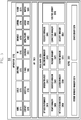
- FIG. 1 is a block diagram illustrating a configuration of an electronic device according to an embodiment of the present disclosure.
- the sensor module 240 may include, for example, an E-nose sensor (not illustrated), an electromyography (EMG) sensor (not illustrated), an electroencephalogram (EEG) sensor (not illustrated), an electrocardiogram (ECG) sensor (not illustrated), a fingerprint sensor (not illustrated), and the like. Additionally or alternatively, the sensor module 240 may include, for example, an E-nose sensor (not illustrated), an EMG sensor (not illustrated), an EEG sensor (not illustrated), an ECG sensor (not illustrated), a fingerprint sensor, and the like. The sensor module 240 may further include a control circuit (not illustrated) for controlling one or more sensors included therein.
- EMG electromyography
- EEG electroencephalogram
- ECG electrocardiogram
- a fingerprint sensor not illustrated
- the sensor module 240 may include, for example, an E-nose sensor (not illustrated), an EMG sensor (not illustrated), an EEG sensor (not illustrated), an ECG sensor (not illustrated), a fingerprint sensor, and the like.
- the sensor module 240 may further include a control
- the display module 260 may include a panel 262, a hologram 264, or projector 266.
- the display module 260 may be, for example, the display module 160 illustrated in FIG. 1 .
- the panel 262 may be, for example, a liquid crystal display (LCD) and an active matrix organic light emitting diode (AM-OLED) display, and the like.
- the panel 262 may be implemented so as to be, for example, flexible, transparent, or wearable.
- the panel 262 may include the touch panel 252 and one module.
- the hologram 264 may display a three-dimensional image in the air by using interference of light.
- the display module 260 may further include a control circuit for controlling the panel 262 or the hologram 264.
- the audio codec 280 may bidirectionally convert between a voice and an electrical signal.
- the audio codec 280 may convert voice information, which is input to or output from the audio codec 280, through, for example, a speaker 282, a receiver 284, an earphone 286, the microphone 288 or the like.
- the power management module 295 may manage power of the hardware 200. Although not illustrated, the power management module 295 may include, for example, a power management integrated circuit (PMIC), a charger integrated circuit (IC), or a battery fuel gauge.
- PMIC power management integrated circuit
- IC charger integrated circuit
- battery fuel gauge battery fuel gauge
- the battery fuel gauge may measure, for example, a residual quantity of the battery 296, or a voltage, a current or a temperature during the charging.
- the battery 296 may supply power by generating electricity, and may be, for example, a rechargeable battery.
- the hardware 200 may include a processing unit (e.g., a GPU) for supporting a module TV.
- the processing unit for supporting a module TV may process media data according to standards such as, for example, digital multimedia broadcasting (DMB), digital video broadcasting (DVB), media flow, and the like.
- DMB digital multimedia broadcasting
- DVD digital video broadcasting
- Each of the above-described elements of the hardware 200 according to an embodiment of the present disclosure may include one or more components, and the name of the relevant element may change depending on the type of electronic device.
- the hardware according to an embodiment of the present disclosure may include at least one of the above-described elements. Some of the above-described elements may be omitted from the hardware, or the hardware may further include additional elements. Also, some of the elements of the hardware according to an embodiment of the present disclosure may be combined into one entity, which may perform functions identical to those of the relevant elements before the combination.
- the "module” may include at least one of an application-specific integrated circuit (ASIC) chip, a field-programmable gate array (FPGA), and a programmable-logic device for performing certain operations that have been known or are to be developed in the future.
- ASIC application-specific integrated circuit
- FPGA field-programmable gate array
- programmable-logic device for performing certain operations that have been known or are to be developed in the future.
- the programming module 310 may be included (or stored) in the electronic device 100 (e.g., the memory 130) or may be included (or stored) in the electronic device 201 (e.g., the memory 230) illustrated in FIG. 1 . At least a part of the programming module 310 may be implemented in software, firmware, hardware, or a combination of two or more thereof.
- the programming module 310 may be implemented in hardware (e.g., the hardware 200), and may include an OS controlling resources related to an electronic device (e.g., the electronic device 100) and/or various applications (e.g., an application 370) executed in the OS.
- the OS may be ANDROID, iOS, WINDOWS, SYMBIAN, TIZEN, BADA, and the like.
- the programming module 310 may include a kernel 320, a middleware 330, an API 360, and/or the application 370.
- the kernel 320 may include a system resource manager 321 and/or a device driver 323.
- the system resource manager 321 may include, for example, a process manager (not illustrated), a memory manager (not illustrated), and a file system manager (not illustrated).
- the system resource manager 321 may perform the control, allocation, recovery, and/or the like of system resources.
- the device driver 323 may include, for example, a display driver (not illustrated), a camera driver (not illustrated), a BLUETOOTH driver (not illustrated), a shared memory driver (not illustrated), a USB driver (not illustrated), a keypad driver (not illustrated), a Wi-Fi driver (not illustrated), and/or an audio driver (not illustrated).
- the device driver 323 may include an inter-process communication (IPC) driver (not illustrated).
- IPC inter-process communication
- the middleware 330 may include at least one of a runtime library 335, an application manager 341, a window manager 342, a multimedia manager 343, a resource manager 344, a power manager 345, a database manager 346, a package manager 347, a connectivity manager 348, a notification manager 349, a location manager 350, a graphic manager 351, a security manager 352, and any other suitable and/or similar manager.
- the application manager 341 may manage, for example, a life cycle of at least one of the applications 370.
- the window manager 342 may manage GUI resources used on the screen.
- the multimedia manager 343 may detect a format used to reproduce various media files and may encode or decode a media file through a codec appropriate for the relevant format.
- the resource manager 344 may manage resources, such as a source code, a memory, a storage space, and/or the like of at least one of the applications 370.
- the power manager 345 may operate together with a basic input/output system (BIOS), may manage a battery or power, and may provide power information and the like used for an operation.
- the database manager 346 may manage a database in such a manner as to enable the generation, search and/or change of the database to be used by at least one of the applications 370.
- the package manager 347 may manage the installation and/or update of an application distributed in the form of a package file.
- the connectivity manager 348 may manage a wireless connectivity such as, for example, Wi-Fi and Bluetooth.
- the notification manager 349 may display or report, to the user, an event such as an arrival message, an appointment, a proximity alarm, and the like in such a manner as not to disturb the user.
- the location manager 350 may manage location information of the electronic device.
- the graphic manager 351 may manage a graphic effect, which is to be provided to the user, and/or a user interface related to the graphic effect.
- the security manager 352 may provide various security functions used for system security, user authentication, and the like.
- the middleware 330 may further include a telephony manager (not illustrated) for managing a voice telephony call function and/or a video telephony call function of the electronic device.
- a telephony manager not illustrated for managing a voice telephony call function and/or a video telephony call function of the electronic device.
- the middleware 330 may generate and use a new middleware module through various functional combinations of the above-described internal element modules.
- the middleware 330 may provide modules specialized according to types of OSs in order to provide differentiated functions.
- the middleware 330 may dynamically delete some of the existing elements, or may add new elements. Accordingly, the middleware 330 may omit some of the elements described in the various embodiments of the present disclosure, may further include other elements, or may replace the some of the elements with elements, each of which performs a similar function and has a different name.
- the API 360 (e.g., the API 145) is a set of API programming functions, and may be provided with a different configuration according to an OS. In the case of Android or iOS, for example, one API set may be provided to each platform. In the case of TIZEN, for example, two or more API sets may be provided to each platform.
- the applications 370 may include, for example, a preloaded application and/or a third party application.
- the applications 370 may include, for example, a home application 371, a dialer application 372, a short message service (SMS)/multimedia message service (MMS) application 373, an instant message (IM) application 374, a browser application 375, a camera application 376, an alarm application 377, a contact application 378, a voice dial application 379, an electronic mail (e-mail) application 380, a calendar application 381, a media player application 382, an album application 383, a clock application 384, and any other suitable and/or similar application.
- SMS short message service
- MMS multimedia message service
- IM instant message
- At least a part of the programming module 310 may be implemented by instructions stored in a non-transitory computer-readable storage medium. When the instructions are executed by one or more processors (e.g., the one or more processors 210), the one or more processors may perform functions corresponding to the instructions.
- the non-transitory computer-readable storage medium may be, for example, the memory 230.
- At least a part of the programming module 310 may be implemented (e.g., executed) by, for example, the one or more processors 210.
- At least a part of the programming module 310 may include, for example, a module, a program, a routine, a set of instructions, and/or a process for performing one or more functions.
- Names of the elements of the programming module may change depending on the type of OS.
- the programming module according to an embodiment of the present disclosure may include one or more of the above-described elements. Alternatively, some of the above-described elements may be omitted from the programming module. Alternatively, the programming module may further include additional elements.
- the operations performed by the programming module or other elements according to an embodiment of the present disclosure may be processed in a sequential method, a parallel method, a repetitive method, or a heuristic method. Also, some of the operations may be omitted, or other operations may be added to the operations.
- the instructions enable the processor to: display the first user interface on the first image-display area; display text or icons related to the second application on the third image-display area; receive a first user input for selecting an item or action via the first image-display area; receive, when the first user input is received, a second user input for selecting the text or the icon via the third image display area; and display the second user interface on the second image-display area, in response to the second user input, and process the item or action, using the second application.
- the first application includes a photo gallery application.
- the second application includes at least one message/email sending application. At least one of the third image-display areas extends from the edge of the first image-display area to the edge of the second image-display area.
- the second user input includes: a user action for dragging an object located in the first image-display area to the text or the icons located in the second image-display area.
- the second user input includes: a user action for dragging the text or the icons located in the second image-display area to an object located in the first image-display area.
- the instructions enable the processor to perform, when executing the second application, linkify to link an object located in the first image-display area with the second image-display area running the second application.
- the instructions enable the processor to: switch a first screen displayed on the first image-display area to a second screen in response to a third user input; and display the first screen on the second image-display area, when switching the first screen to the second screen on the first image-display area.
- the instructions enable the processor to allow the first and second image-display areas to display: screens on which the same application is running; and the same information included in the execution screens in different forms, respectively.
- the instructions enable the processor to allow the first and second image-display areas to display screens on which the same application is running, wherein information of the execution screen shown on the first image-display area is shown on the second image-display area.
- the second display 420 facing a second direction is mounted on the rear side of the electronic device.
- the second direction is opposite the first direction.
- the electronic device may include a camera 421 and a flash 422 for taking images at the top above the second display 420.
- the electronic device includes a third display 430 and fourth display 440 at both sides, respectively.
- the third and fourth displays 430 and 440 may be extended from the first display 410 or the second display 420.
- the first to fourth display 410, 420, 430, and 440 may be continuously connected to each other.
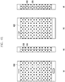
- Fig. 5 is a cross-sectional view of an electronic device according to various embodiments of the present invention.
- Fig. 5 is a cross-sectional view of an electronic device shown in Fig. 4 .
- the electronic device may be protected by a hosing 552 as a casing member.
- the housing 552 encases parts of the electronic device therein.
- the housing 552 is configured to form a hollow space receiving an operation circuit, a power circuit, a communication circuit, a battery 551, etc., related to the operations of the electronic device.
- the operation circuit and the power circuit may be implemented on a printed circuit board (PCB) 553.
- PCB printed circuit board
- the outer surface of the housing 552 includes: a first side that faces a first direction and is covered by a first display 510; a second side that faces a second direction and is covered by a second display 520; sides each of which encloses parts between the first and second sides and each of which are covered by third and fourth displays 530 and 540, respectively.
- the first to fourth display 510, 520, 530, and 540 of the outer surface of the housing 552 may be continuously connected to each other. Therefore, the electronic device includes the first image-display area on the first side, the second image-display area on the second side, and the third image-display areas on the sides.
- the housing 552 includes a bezel 541, on the side covered by the fourth display 540, for dividing the fourth display 540 into two parts.
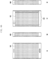
- Figs. 6A to 6C show diagrams of the outward appearance of an electronic device according to various embodiments of the present invention.
- an electronic device is capable of including third and fourth displays 630 and 640 on both sides, each of which is formed to be divided into two parts.
- the electronic device is capable of including the third display 630 on one side.
- the third display 630 may be formed in such a way that the first and second displays 610 and 620 extend to one side, respectively.
- the third display 630 is split into two parts by a first bezel 631 in the lengthwise direction.
- the electronic device is capable of including the fourth display 640 on the other side.
- the fourth display 640 may be formed in such a way that the first and second displays 610 and 620 extend to the other side, respectively.
- the fourth display 640 is split into two parts by a second bezel 641 in the lengthwise direction.
- an electronic device includes displays on a front side, a rear side, and one of the sides.
- the electronic device includes: a first display 610 on the front side and a second display 620 on the rear side as shown in Fig. 6C ; and a third display 630 on one of both sides as shown in diagram (b) of Fig. 6C .
- the electronic device may not include a display on the other side 650 of both sides.
- Fig. 7 is a detailed cross-sectional view of an electronic device according to various embodiments of the present disclosure.
- the bent part of the middle frame 720 is a part (parts) at one or more side ends of the middle frame 720, which is (are) slidably coupled to the rail member 750 and fitted into the groove 741 of the side frame 740.
- the bent part of the middle frame 720 is designed in such a way that the end of the middle frame 720 is bent at least two times and forms a step at the end of the flat part supporting the display 710. It should be understood that the bent part may be implemented in various forms. Since the electronic device according to an embodiment includes the rail member 750 into which the bent part of the middle frame 720 is slidably fitted from the end, it can be easily assembled, and this leads to increase the productivity and yield.
- Fig. 8 is a diagram showing the configuration of an electronic device according to various embodiments of the present disclosure. More specifically, Fig. 8 is a side view of an electronic device.
- an electronic device is capable of including at least one hole (obstacle) 830 inside an image-display area of a display 805.
- the hole 830 may be an obstacle to dispose a user input button.
- an electronic device may be designed in such a way that a display 805 is disposed on at least one side and a user input button is formed on the side where the display 805 is disposed.
- the user input button may be disposed in the hole 830 formed inside the image-display area of the display 805.
- the electronic device is designed in such a way that: a display 805 with a hole 830 is located at one side (front/rear) of the electronic device and an operation circuit 820 for driving the display 805 is located at the bottom (or top) of the display 805.
- the display 805 includes a number of signal lines in a matrix form for providing video data output from the operation circuit 820 to a number of pixels. In this case, part of the signal lines, between the hole 830 and the operation circuit 820, do not maintain the linearity, which is because the hole 830 serves as an obstacle.
- the display 805 may show a video on a first region A1 where the hole 830 and the operation circuit 820 face each other on the strait line between the hole 830 and the operation circuit 820 because the linearity of the signal lines is maintained; however, the display 805 may not show a video on a second region A2 that corresponds to the other region, except for the first region A1, because the linearity of the signal lines is not maintained by the hole 830.
- the first region A1 is referred to as a region that is located between the top end of the display 805 and the hole 830 on the straight line in which the hole 830 and the operation circuit 820 face each other. If the operation circuit 820 is located at the top of the display 805, the first region A1 and the second region A2 may change their locations with each other.
- the electronic device may be implemented in such a way that operation circuits are installed to both of the top and bottom of the display 805 and take charge of the display on the first and second regions A1 and A2, respectively.
- the electronic device includes: a first operation circuit 820 at the bottom of the display 805 so that the first operation circuit 820 can drive an image-display area corresponding to the first region A1; and a second operation circuit 810 at the top of the display 805 so that the second operation circuit 810 can drive an image-display area corresponding to the second region A2.
- the electronic device may allow one of the first and second operation circuits 810 and 820 to drive an image-display area corresponding to the remaining region, except for the first and second regions A1 and A2.
- the electronic device Since the electronic device according to an embodiment is implemented to include operation circuits 810 and 820 for operation the display 805 at the top and bottom of the display 805 respectively, although a hole 830 is formed inside an image-display area of the display 805, the electronic device is capable of displaying a video on all the region except for the hole 830.
- Fig. 9 shows diagrams that describe a metal key of an electronic device according to various embodiments of the present disclosure.
- Fig. 10 is a detailed diagram of a metal key of an electronic device according to various embodiments of the present disclosure.
- an electronic device 900 may be designed in such a way that a user operation button (user operation buttons) is (are) included in at least one side of the housing.
- the housing of the electronic device 900 may be made of a metal material.
- the user operation button may be formed as a non-protrusion structure.
- the electronic device 900 includes a bezel 910 in at least one of the sides of the housing, for dividing the display extended, in the side direction, from an edge of the front side or rear side, into two displays in the lengthwise of the display.
- the bezel 910 may be made of a metal material.
- the bezel 910 includes at least one user operation button.
- the user operation button may be formed in non-protrusion structure. As shown in diagram (b) of Fig. 9 , the user operation button may be implemented to include: an insulator 930 formed in part of the bezel 910; and a metal key 920 that is formed inside the insulator 930 and spaced apart from the metal material of the bezel 910.
- the insulator 930 may be shaped in circle or polygon. Part of the margin of the bezel 910 may be formed at both sides of the insulator 930. Therefore, the bezel 910 may have a non-division form in a region where the user operation button is located.
- the user operation button detects a user input via mutual capacitance.
- the metal key 920 is designed in a single layer or double layers.
- the metal key 920 is designed in a single layer. As shown in diagram (d) of Fig. 9 , the metal key 920 is designed in double layers further including a second metal key 925 that is located below the metal key 920 and overlaps the metal key 920, seen from the top.
- an electronic device may be designed in such a way that a bezel is divided by a user operation button.
- the user operation button may include a number of insulators 1030 configured to divide the bezel into parts in the width direction.
- the user operation button may include: a first insulator in a region, for dividing a bezel into two parts in the width direction; a second insulator spaced apart from the first insulator, for dividing the bezel into two parts in the width direction; and a metal key 1020 located between the first and second insulators.
- a method of operating an electronic device is implemented to include: executing a first application, and displaying a first user interface on a first image-display area; displaying text or icons related to a second application on a third image-display area; receiving a first user input for selecting an item or action via the first image-display area; receiving, when receiving the first user input, a second user input for selecting the text or the icon via the third image-display area; and displaying the second user interface on the second image-display area, in response to the second user input, and processing the item or action, using the second application.
- the first application includes a photo gallery application.
- the second application includes at least one message/email sending application.
- the reception of a second user input includes: receiving a user action for dragging an object located in the first image-display area to the text or the icons located in the second image-display area.
- the reception of a second user input includes: receiving a user action for dragging the text or the icons located in the second image-display area to an object located in the first image-display area.
- the method may further include: performing, when executing the second application, linkify to link an object located in the first image-display area with the second image-display area running the second application.
- the method may further include: switching a first screen displayed on the first image-display area to a second screen in response to a third user input; and displaying the first screen on the second image-display area, when switching the first screen to the second screen on the first image-display area.
- the method may further include allowing the first and second image-display areas to display: screens on which the same application is running; and the same information included in the execution screens in different forms, respectively.
- the method may further include: allowing the first and second image-display areas to display screens on which the same application is running, wherein information of the execution screen shown on the first image-display area is shown on the second image-display area.
- the method may further include: executing a third application in response to a user input; and allowing the first to third image-display areas to display corresponding partial screens of a single screen, respectively, and displaying the single screen formed as the partial screens shown on the first to third image-display areas are successively connected to each other.
- the third application includes: a map search application and/or a photo gallery application.
- Fig. 11 is a block diagram of an electronic device according to various embodiments of the present disclosure.
- an electronic device is capable of including a display 1120, a communication circuit 1150, an input unit 1130, a memory 1140, and a processor 1110.
- the display 1120 (e.g., display 260) is capable of displaying data/information input by a user and provided to the user, as well as various menus for the electronic device 1100.
- the display 1120 is capable of providing various types of screens according to the operations of the electronic device 1100, such as an idle screen (home screen), menu screens, a message writing screen, a call screen, schedule management screen, contacts screen, web-page output screens, etc.
- the display 1120 may be implemented with a liquid crystal display (LCD), organic light emitting diodes (OLEDs), active matrix organic light emitting diodes (AMOLEDs), or the like.
- OLEDs organic light emitting diodes
- AMOLEDs active matrix organic light emitting diodes
- the display 1120 may be formed to enclose the sides of the electronic device, including a number of image-display areas corresponding to the sides.
- the display 1120 includes: a first display on the front side (e.g., first side) of the electronic device; a second display on the rear side (e.g., second side) of the electronic device; and a third display (third displays) on a side (sides) of the electronic device.
- An area displaying a video via the first display is defined as a first image-display area.
- An area displaying a video via the second display is defined as a second image-display area.
- An area displaying a video via the third display is defined as a third image-display area.
- the first to third displays is capable of operating independently, respectively, under the control of the processor 1110, displaying different videos or successive parts of a video.
- the first to third displays may display videos in various modes according to the method of operating an electronic device, which will be described in detail later.
- the communication circuit 1150 (e.g., communication module 220) establishes, with a base station, a communication cannel for a call (e.g., a voice call, a video call, etc.) and a data communication channel for the transmission of data.
- the communication circuit 1150 includes: an RF transmitter for up-converting the frequency of signals to be transmitted and amplifying the signals, an RF receiver for low-noise amplifying received RF signals and down-converting the frequency of the received RF signals, a transmission/reception separator for separating transmission signals and reception signals, etc.
- the input unit 1130 (e.g., input unit 250) includes input keys and function keys that receive numerical or alphabetical information and set and control a variety of functions in the electronic device 1100.
- the input unit 1130 may be implemented with one of the following: a button-type key pad, a ball joystick, an optical joystick, a wheel key, a touch key, a touch pad, a touch screen, etc., or a combination thereof.
- the memory 1140 (e.g., memory 230) is capable of storing: an operating system (OS) of the electronic device 1100; applications required for option functions, e.g., an audio playback function, image/video playback function, broadcast playback function, etc.; user data, data transmitted during the communication, etc.
- OS operating system
- the memory 1140 is capable of storing video files, game files, music files, movie files, etc.
- the processor 1110 controls the entire operation of the electronic device 1100 and the signals between the components in the electronic device 1100.
- the processor 1110 also performs a data process function.
- the processor 1110 may be a central processing unit (CPU), a micro-processor unit (MPU), an application processor (AP), etc.
- the processor 1110 is capable of executing an application, providing a user interface via a display, and controlling the first to third displays to show screens in response to user inputs.
- the following description provides a detailed description regarding a method for a processor to control the first to third displays to show screens.
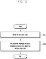
- Fig. 12 is a flowchart that describes operations of an electronic device according to various embodiments of the present disclosure.
- the electronic device is capable of simultaneously using activated areas of the display. Alternatively, the electronic device is also capable of controlling activated areas, independently, respectively.
- the processor e.g., the application processor 210 shown in Fig. 2
- the processor is capable of detecting at least one input in operation 1201.
- at least one input may be created by various types of input units of the electronic device (e.g., the electronic device 101 shown in Fig. 1 ).
- At least one input may be information obtained from at least one sensor (e.g., the sensor module 240 shown in Fig. 2 ).
- At least one input may be a signal received from external systems, e.g., an incoming call signal, a message reception signal, etc.
- At least one input may also include a start operation of a pre-defined application.
- the application processor 210 is capable of setting an activated display area based on at least one input in operation 1203.
- Fig. 13 is a flowchart that describes a method 1302 of setting an activated display area, based on at least one input, according to various embodiments of the present disclosure.
- Figs. 14 and 15 show diagrams that describe operations of an electronic device adapted to the method of the flowchart as shown in Fig. 13 , according to an embodiment of the present disclosure.
- the processor e.g., the application processor 210 shown in Fig. 2
- the processor is capable of detecting the wake-up signal in operation 1301.
- a wake-up signal may be generate by pressing a button, by inputting a pre-defined type of touch, and/or by applying a hovering input, etc.
- a wake-up signal may be a signal detected by at least one sensor.
- a wake-up signal may be an incoming call signal, the reception of a text message or a social network service (SNS) message, etc.
- SNS social network service
- the application processor 210 is capable of setting the first activated display area in operation 1303.
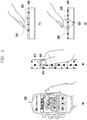
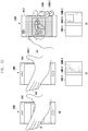
- FIG. 14 With reference to diagram (a) of Fig. 14 , if an electronic device 1400 is placed on a flat so that the front side faces upward, the first side 1411 is exposed but the second side 1412 is not exposed. If a hovering input or a touch input, such as a flick gesture, a double tap, etc., is applied to a first display area 1460-1 of the first side 1411, the screen of the first display area 1460-1 is unlocked and displays corresponding content 1440.
- a hovering input or a touch input such as a flick gesture, a double tap, etc.
- the application processor 210 is capable of detecting the pre-defined input in operation 1307. For example, as shown in diagram (a) of Fig. 15 , when the user grips the electronic device 1400 with the hand 14, part of the user's hand 14 may continuously apply the touch or hovering input to the display 1460, and this may generate a pre-defined input.
- the application processor 210 measures a turn angle of the electronic device 1400, and determines whether the turn angle is greater than a threshold in operation 1313. If the application processor 210 ascertains that the turn angle is greater than a threshold in operation 1313, it is capable of setting a second activated display area in operation 1309. For example, as shown in diagram (b) of Fig. 14 , if the electronic device 1400 is turned over from the position shown in diagram (a) of Fig. 14 , so that the second side 1412 is disclosed and the first side 1411 is disclosed, the application processor 210 ascertains that the turn angle of the electronic device is greater than a threshold. The application processor 210: switches the first display area 1460-1 from an activated state to an inactivated state, and the second display area 1460-2 from an inactivated state to an activated state; and displays the content 1440 on the second display area 1460-2.
- the application processor 210 is capable of setting a second activated display area in operation 1309. For example, as shown in diagrams (b) and (c) of Fig. 15 , if the user grips the electronic device 1400, part of the user's hand 14 may apply the touch or hovering input to first display area 1460-1 of the display 1460, and this may generate a pre-defined input.
- the application processor 210 switches the first display area 1460-1 from an activated state to an inactivated state, and the second display area 1460-2 from a de-activate state to an activated state; and displays the content 1440 on the second display area 1460-2.
- the application processor 210 is capable of setting a third activated display area in operation 1303 or 1309.
- the activated area and the inactivated area in the third display area 1460-3 may be adjusted according to the content displayed on the first display area 1460-1 or the second display area 1460-2.
- the application processor 210 is capable of activating part of a third display area 1460-3 by the size of the content 1440 and inactivating the remaining part of the third display area 1460-3.
- the third display area 1460-3 may be separated from the display via an inactivated area or physically as shown in Fig. 6A or 6B .
- the display 1460 shown in Fig. 14 may further include an additional display area of a fourth display area 1460-4 or fifth display area 1460-5.
- the application processor 210 is capable of activating part of the fourth display area 1460-3 or fifth display area 1460-5 by the size of the content 1440 and inactivating the remaining part of the fourth display area 1460-4 or fifth display area 1460-5.
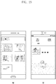
- Fig. 16 shows diagrams of various types of screen provided by an electronic device according to various embodiments of the present disclosure.
- Fig. 17 shows diagrams of a background screen provided by an electronic device according to various embodiments of the present disclosure.
- Fig. 18 shows diagrams that describe a method of operating an electronic device according to various embodiments of the present disclosure.
- Fig. 19 shows diagrams that describe a method for an electronic device to provide an incoming call notification according to various embodiments of the present disclosure.
- Fig. 20 shows diagrams that describe a method for an electronic device to provide an incoming call notification according to various embodiments of the present disclosure.
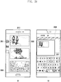
- Fig. 21 shows diagrams of screens provided by an electronic device according to various embodiments of the present disclosure.
- Fig. 21 shows diagrams of screens provided by an electronic device according to various embodiments of the present disclosure.
- FIG. 22 shows diagrams of screens provided by an electronic device according to various embodiments of the present disclosure.
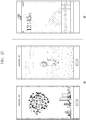
- Fig. 23 shows diagrams of screens when an electronic device runs a media playback application according to various embodiments of the present disclosure.
- Fig. 24 shows diagrams of screens when an electronic device runs a clock application according to various embodiments of the present disclosure.
- Fig. 25 shows diagrams of idle screens when an electronic device operates in an idle mode according to various embodiments of the present disclosure.
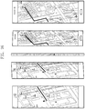
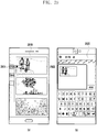
- Fig. 26 shows diagrams of screens when an electronic device runs a map search application according to various embodiments of the present disclosure.
- the processor 1110 executes one of a number of applications stored in the memory 1140, referring to the memory 1140, and provides a user interface to at least one display.
- first, second and third applications may include first, second and third user interfaces respectively.
- the processor 1110 is capable of executing one of the applications, and providing different user interface screens to first to third displays, respectively.
- the processor 1110 controls the first and second displays to display: screens on which the same application is running; and the same information included in the execution screens in different forms, respectively.
- an example of the application executed by the processor 1110 is a web-browser.
- the processor 1110 executes a web-browser and controls the first and second displays to display web screens respectively.
- the processor 1110 may allow the first and second displays to show the web-browser screens in different forms respectively.
- the processor 1110 may provide a web screen of a "PC version" to the first display of the front side of the electronic device.
- the processor 1110 may provide a web screen of a "mobile version" to the second display of the rear side of the electronic device.
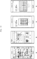
- Another example of the application executed by the processor 1110 is a calculator application.
- the processor 1110 executes a calculator application and controls the first and second displays to display calculator screens respectively. In this case, the processor 1110 may allow the first and second displays to show the calculator screens in different forms respectively. For example, as shown in diagram (c) of Fig.
- the processor 1110 may provide a calculator screen of a "basic calculator” form to the first display of the front side of the electronic device.
- the processor 1110 may provide a calculator screen of a "scientific calculator” form to the second display of the rear side of the electronic device.
- the processor 1110 is capable of controlling the first and second displays to display background screens (home screens) that differ from each other, respectively.
- the processor 1110 controls the first display to display a background screen of a first type.
- the processor 1110 also controls the second display to display a background screen of a second type.
- the background screen of a first type may be a default home screen provided by smartphone manufacturers.
- the background screen of a first type may show icons corresponding to a number of applications and a folder containing at least one icon.
- the background screen of a second type may be a screen provided when a smartphone runs in an easy mode.
- the background screen of a second type may show icons larger in size and less in number than the background screen of a first type.
- the background screen of a second type may only show icons corresponding to frequently used applications, e.g., a call function, a camera function, an Internet function, a messenger function, etc.
- the electronic device according to an embodiment is capable of displaying a user interface provided by one application on multiple displays in various modes that differ from each other, thereby increasing user convenience.
- the processor 1110 is capable of executing one of a number of applications, switching a screen displayed on a display (display 1) in response to a user input, and performing, when the screen displayed on the display (display 1) is switched, a control operation so that a screen previously displayed on the display (display 1) can be displayed on another display.
- the application execute by the processor 1110 may be a web-browser.
- the processor 1110 is capable of providing: a first web screen 1801 of the web-browser executed on the first display, and a first user interface; and a second web screen 1802 on the second display.
- the screen displayed on the second display may not be a second web screen, but may be a second user interface according to the execution of another application.
- the processor 1110 is capable of switching: a first web screen 1801 displayed on the first display into a third web screen 1803; and a second web screen 1802 displayed on the second display into the first web screen 1801. While a web screen is switched on the first display, if the second display provides a second user interface according to the execution of another application, the processor 1110 is capable of performing a control operation so that the second display can provide a previous screen of the first display from the second user interface.
- the electronic device according to an embodiment is capable of controlling, using a multiple display device, one display to display a previous screen provided by another display, thereby increasing user convenience.
- the processor 1110 when the electronic device receives a call, the processor 1110 provides a notification of an incoming call to a first or second display.
- the processor 1110 may also provide a notification of an incoming call in other mode.
- the processor 1110 may provide a notification in various modes according to positions (postures) of an electronic device.
- FIG (a) of Fig. 19 when the electronic device is placed so that the first display faces upwards and the second display faces downwards, the processor 1110 is capable of displaying a caller's phone number and information regarding the caller on the first display, and also providing a ringtone or a vibration notification.
- the processor 1110 when the electronic device is placed so that the first display faces downwards and the second display faces upwards, the processor 1110 is capable of displaying only a caller's phone number on the second display, without providing a ringtone and a vibration notification.
- the processor 1110 is capable of: providing a caller's phone number and information regarding the caller to the first display; and controlling the second display to display a screen previously displayed on the first display.
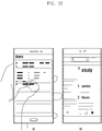
- the processor 1110 when the electronic device receives a call while the user is using an application "SMON", the processor 1110 is capable of displaying; a caller's phone number and information regarding the caller on the first display as shown in diagram (a) of Fig. 20 .
- the processor 1110 is capable of displaying a user interface of the application "SMON", previously displayed on the first display before receiving the call, on the second display as shown in diagram (b) of Fig. 20 .
- the user can resume using the application that the user has used via the second display.
- the processor 1110 is capable of controlling one display to display information of a screen currently displayed on another display.
- the processor 1110 is capable of: executing one of a number of applications; providing a first user interface to one display; and controlling one display to display information of the first user interface on another display, via the first user interface, in response to a user input.
- the processor 1110 is capable of executing a map search application and providing a map screen to the first display.
- the processor 1110 receives and detects a user input selecting a specified region on the first display via the first user interface, and displays a detailed map screen corresponding to the specified region on the second display.
- the user input selecting a specified region may be one or more of the following: a single touch, a multi touch, a tap/touch, and a pressure touch.
- a single touch For example, when a user needs to zoom in on a location where a terminal is located on the map screen on the first display, the user may apply multi-touches to the location where the terminal is located on the map screen.
- the processor 1110 detects the multi-touches, identifies the multi-touched region, and displays a map enlarging the location on the second display.
- the processor 1110 is capable of executing a destination search application, and displaying, on the first display, a screen providing offered paths according to the destination search.
- the processor 1110 receives and detects a user input selecting one of the offered paths on the first display, via the first user interface, and displays the selected, offered path, in detail, on the second display.
- the processor 1110 is capable of executing a dictionary search application.
- the processor 1110 is capable of providing the first display with a list of words according to the dictionary search result.
- the processor 1110 is capable of detecting a user input selecting one of the words on list on the first display via a first user interface.
- the processor 1110 receives the user input, it is capable of providing the user's selected word, the definition, the related words, etc., to the second display.
- the processor 1110 may execute various applications as well as the map search application, the destination search application, and the dictionary search application; and may enable one of a number of displays to display information or information related to a screen previously provided to another display.
- the processor 1110 is capable of executing a media playback application.
- the processor 1110 is capable of executing a media playback application and providing a playlist to the first display.
- the processor 1110 is capable of providing the second display with shortcut keys for controlling media playback (e.g., a hot key).
- the shortcut keys may include a number of buttons: previous, next, paly, pause, stop, etc., and an album jacket, etc.
- the processor 1110 may also control the second display to provide preset shortcut keys, e.g., shortcut keys for providing a camera function, a picture-memo function, etc.
- the processor 1110 is capable of executing a clock application.
- the processor 1110 is capable of executing a clock application according to a user input or when the electronic device is in a screen-lock sate (or an idle mode).
- the processor 1110 is capable of displaying clock information in one form on the first display and in another form on the second display.
- the processor 1110 is capable of providing the first and second displays with the clock images that differ in design and color from each other.
- the processor 1110 is capable of displaying an analog clock on the first display and a digital clock on the second display.
- the processor 1110 is capable of displaying an analog clock on both of the first and second displays.
- the processor 1110 may set the analog clocks displayed on the first and second displays to differ from each other in outer border, background, hand, or size. As shown in diagrams (c) and (d) of Fig. 24 , the processor 1110 is capable of providing the same screen to the first and second displays.
- the processor 1110 is capable of displaying successive screens on a number of displays.
- the processor 1110 is capable of executing an application in response to a user input, and displaying parts of one screen of the executed application, successively, on first to third displays.
- the processor 1110 is capable of executing a map search application.
- the processor 1110 is capable of displaying parts of the map screen created according to the map search application, successively, on the first to third displays.
- the processor 1110 is capable of dividing a specified local area on the map into a number of areas.
- the electronic device is capable of displaying, on one of a number of displays/display areas, information of a screen currently displayed another display/display area, thereby providing user convenience.
Description
- The present disclosure relates to a multiple display device with a number of display areas, and a method of operating the device.
- A multiple display device is referred to as a device that is configured to include a number of display areas and allows users to view images shown on the display areas. A multiple display device may also provide interfaces to the display areas, so that users can easily access the interface on any of the display areas.
- However, a multiple display device has the difficulty of being assembled or implemented because its body needs to be enclosed by the display areas. In addition, the multiple display device has not had various and convenient interfaces
-
US 2005/0264471 A1 discloses a thin display device having a plurality of panels and an electronic apparatus using such a display device. -
US 2016/0048316 A1 discloses a method for providing a user interface, in which an electronic device divides a display region into a main region and a sub-region and displays default information or event information on the sub-region. -
US 2014/0062976 A1 discloses a terminal including a sensor to sense bending of a flexible display and a controller to control display of information on the display. -
EP 2626852 A2 discloses a display apparatus. -
US 2013/076591 A1 discloses a multi-display device adapted to turn on and off certain device functionality based on one or more of device state and triggers. -
US 2016/070423 A1 discloses systems, methods and GUIs for combined switching and placement of windows based on a single action. - To address the above-discussed deficiencies, it is a primary object to provide a multiple display device that is easily assembled and implanted and provides various interfaces to a number of display areas so that user can easily use the interface on the display areas. Various embodiments also provide a method of operating the multiple display device.
- In accordance with a first aspect of the present invention, there is provided an electronic device according to
claim 1. - In accordance with a second aspect of the present invention, there is provided a method according to
claim 8. - Also disclosed is an electronic device. The electronic device includes: a housing including a first side facing a first direction, a second side facing a second direction opposite the first direction, and sides each of which partially encloses both edges of the first and second sides; a display including a first image-display area on the first side, a second image-display area on the second side, and third image-display areas on the sides; a communication circuit configured to perform wireless communication with an external device; a processor that is located in the housing and is electrically connected to the display and the communication circuit; and a memory that is located in the housing, is electrically connected to the processor, and stores a first application with a first user interface, a second application with a second user interface, and instructions. The instructions enable the processor to: display the first user interface on the first image-display area; display text or icons related to the second application on the third image-display area; receive a first user input for selecting an object located in the first image-display area; receive, when the first user input is received, a second user input for selecting the text or the icon located in the third image-display area; and display the second user interface on the second image-display area, in response to the second user input, and execute corresponding to the text or the icon.
- Also disclosed is a method of operating a multiple display device. The method includes: executing a first application, and displaying a first user interface on a first image-display area; displaying text or icons related to a second application on a third image-display area; receiving a first user input for selecting an object located in the first image-display area; receiving, when the first user input is received, a second user input for selecting the text or the icon located in the third image-display area; and executing the second application corresponding to the text or the icon, and displaying a second user interface on the second image-display area.
- Before undertaking the DETAILED DESCRIPTION below, it may be advantageous to set forth definitions of certain words and phrases used throughout this patent document: the terms "include" and "comprise," as well as derivatives thereof, mean inclusion without limitation; the term "or," is inclusive, meaning and/or; the phrases "associated with" and "associated therewith," as well as derivatives thereof, may mean to include, be included within, interconnect with, contain, be contained within, connect to or with, couple to or with, be communicable with, cooperate with, interleave, juxtapose, be proximate to, be bound to or with, have, have a property of, or the like; and the term "controller" means any device, system or part thereof that controls at least one operation, such a device may be implemented in hardware, firmware or software, or some combination of at least two of the same. It should be noted that the functionality associated with any particular controller may be centralized or distributed, whether locally or remotely. Definitions for certain words and phrases are provided throughout this patent document, those of ordinary skill in the art should understand that in many, if not most instances, such definitions apply to prior, as well as future uses of such defined words and phrases.
- For a more complete understanding of the present disclosure and its advantages, reference is now made to the following description taken in conjunction with the accompanying drawings, in which like reference numerals represent like parts:
-
Fig. 1 illustrates a network environment including an electronic device according to various embodiments of the present invention; -
Fig. 2 illustrates a block diagram of an electronic device according to various embodiments of the present invention; -
Fig. 3 illustrates a block diagram of a program module according to various embodiments of the present invention; -
Fig. 4 illustrates diagrams of the outward appearance of an electronic device according to various embodiments of the present invention; -
Fig. 5 illustrates a cross-sectional view of an electronic device according to various embodiments of the present invention; -
Figs. 6A ,6B and6C illustrate diagrams of the outward appearance of an electronic device according to various embodiments of the present invention; -
Fig. 7 illustrates a detailed cross-sectional view of an electronic device according to various embodiments of the present invention; -
Fig. 8 illustrates a diagram showing the configuration of an electronic device according to various embodiments of the present invention; -
Fig. 9 illustrates diagrams that describe a metal key of an electronic device according to various embodiments of the present invention; -
Fig. 10 illustrates a detailed diagram of a metal key of an electronic device according to various embodiments of the present invention; -
Fig. 11 illustrates a block diagram of an electronic device according to various embodiments of the present invention; -
Fig. 12 illustrates a flowchart that describes operations of an electronic device according to various embodiments of the present invention; -
Fig. 13 illustrates a flowchart that describes a method of setting an activated display area, based on at least one input, according to various embodiments of the present invention; -
Fig. 14 illustrates diagrams that describe operations of an electronic device adapted to the method of the flowchart as shown inFig. 13 , according to an embodiment of the present invention; -
Fig. 15 illustrates diagrams that describe operations of an electronic device adapted to the method of the flowchart as shown inFig. 13 , according to an embodiment of the present invention; -
Fig. 16 illustrates diagrams of various types of screen provided by an electronic device according to various embodiments of the present invention; -
Fig. 17 illustrates diagrams of a background screen provided by an electronic device according to various embodiments of the present invention; -
Fig. 18 illustrates diagrams that describe a method of operating an electronic device according to various embodiments of the present invention; -
Fig. 19 illustrates diagrams that describe a method for an electronic device to provide an incoming call notification according to various embodiments of the present invention; -
Fig. 20 illustrates diagrams that describe a method for an electronic device to provide an incoming call notification according to various embodiments of the present invention; -
Fig. 21 illustrates diagrams of screens provided by an electronic device according to various embodiments of the present invention; -
Fig. 22 illustrates diagrams of screens provided by an electronic device according to various embodiments of the present invention; -
Fig. 23 illustrates diagrams of screens when an electronic device runs a media playback application according to various embodiments of the present invention; -
Fig. 24 illustrates diagrams of screens when an electronic device runs a clock application according to various embodiments of the present invention; -
Fig. 25 illustrates diagrams of idle screens when an electronic device operates in an idle mode according to various embodiments of the present invention; -
Fig. 26 illustrates diagrams of screens when an electronic device runs a map search application according to various embodiments of the present invention; -
Fig. 27 illustrates a diagram of a screen when an electronic device runs a photography application according to various embodiments of the present invention; -
Fig. 28 illustrates diagrams that describe a method of operating an electronic device according to various embodiments of the present invention; -
Fig. 29 illustrates diagrams that describe a method of operating an electronic device according to various embodiments of the present invention; -
Fig. 30 illustrates diagrams that describe a method of operating an electronic device according to various embodiments of the present invention; and -
Fig. 31 illustrates diagrams that describe a method of operating an electronic device according to various embodiments of the present invention. -
FIGURES 1 through 31 , discussed below, and the various embodiments used to describe the principles of the present disclosure in this patent document are by way of illustration only and should not be construed in any way to limit the scope of the disclosure. Those skilled in the art will understand that the principles of the present disclosure may be implemented in any suitably arranged electronic device. - The following description with reference to the accompanying drawings is provided to assist in a comprehensive understanding of various embodiments of the present disclosure as defined by the claims and their equivalents. It includes various specific details to assist in that understanding but these are to be regarded as merely exemplary. Accordingly, those of ordinary skill in the art will recognize that various changes and modifications of the various embodiments described herein can be made without departing from the scope of the present disclosure. In addition, descriptions of well-known functions and constructions may be omitted for clarity and conciseness.
- The terms and words used in the following description and claims are not limited to the bibliographical meanings, but, are merely used by the inventor to enable a clear and consistent understanding of the present disclosure. Accordingly, it should be apparent to those skilled in the art that the following description of various embodiments of the present disclosure is provided for illustration purpose only and not for the purpose of limiting the present disclosure as defined by the appended claims and their equivalents.
- It is to be understood that the singular forms "a," "an," and "the" include plural referents unless the context clearly dictates otherwise. Thus, for example, reference to "a component surface" includes reference to one or more of such surfaces.
- The expressions such as "include" and "may include" may denote the presence of the disclosed functions, operations, and constituent elements and do not limit one or more additional functions, operations, and constituent elements. Terms such as "include" and/or "have" may be construed to denote a certain characteristic, number, operation, constituent element, component or a combination thereof, but may not be construed to exclude the existence of or a possibility of addition of one or more other characteristics, numbers, operations, constituent elements, components or combinations thereof.
- Furthermore, in the present disclosure, the expression "and/or" includes any and all combinations of the associated listed words. For example, the expression "A and/or B" may include A, may include B, or may include both A and B.
- In the present disclosure, expressions including ordinal numbers, such as "first" and "second," etc., may modify various elements. However, such elements are not limited by the above expressions. For example, the above expressions do not limit the sequence and/or importance of the elements. The above expressions are used merely for the purpose to distinguish an element from the other elements. For example, a first user device and a second user device indicate different user devices although both of them are user devices. For example, a first element could be termed a second element, and similarly, a second element could be also termed a first element without departing from the scope of the present disclosure.
- In the case where a component is referred to as being "connected" or "accessed" to other component, it should be understood that not only the component is directly connected or accessed to the other component, but also there may exist another component between them. Meanwhile, in the case where a component is referred to as being "directly connected" or "directly accessed" to other component, it should be understood that there is no component therebetween. The terms used in the present disclosure are only used to describe specific various embodiments, and are not intended to limit the present disclosure. As used herein, the singular forms are intended to include the plural forms as well, unless the context clearly indicates otherwise. Singular forms are intended to include plural forms unless the context clearly indicates otherwise.
- An electronic device according to the present disclosure may be a device including a communication function. For example, the device corresponds to a combination of at least one of a smartphone, a tablet personal computer (PC), a mobile phone, a video phone , an e-book reader, a desktop PC, a laptop PC, a netbook computer, a personal digital assistant (PDA), a portable multimedia player (PMP), a digital audio player, a mobile medical device, an electronic bracelet, an electronic necklace, an electronic accessory, a camera, a wearable device, an electronic clock, a wrist watch, home appliances (for example, an air-conditioner, vacuum, an oven, a microwave, a washing machine, an air cleaner, and the like), an artificial intelligence robot, a television (TV), a digital video disk (DVD) player, an audio device, various medical devices (for example, magnetic resonance angiography (MRA), magnetic resonance imaging (MRI), computed tomography (CT), a scanning machine, a ultrasonic wave device, or the like), a navigation device, a global positioning system (GPS) receiver, an event data recorder (EDR), a Flight data recorder (FDR), a set-top box, a TV box (for example, SAMSUNG HOMESYNC TM, APPLE TV TM, or GOOGLE TV TM), an electronic dictionary, vehicle infotainment device, an electronic equipment for a ship (for example, navigation equipment for a ship, gyrocompass, or the like), avionics, a security device, electronic clothes, an electronic key, a camcorder, game consoles, a head-mounted display (HMD), a flat panel display device, an electronic frame, an electronic album, furniture or a portion of a building/structure that includes a communication function, an electronic board, an electronic signature receiving device, a projector, and the like. It is obvious to those skilled in the art that the electronic device according to the present disclosure is not limited to the aforementioned devices.
-
FIG. 1 is a block diagram illustrating a configuration of an electronic device according to an embodiment of the present disclosure. - Referring to
FIG. 1 , theelectronic device 100 may include abus 110, aprocessor 120, amemory 130, auser input module 150, adisplay module 160, acommunication module 170, and other similar and/or suitable components. - The
bus 110 may be a circuit that interconnects the above-described elements and delivers a communication (e.g., a control message) between the above-described elements. - The
processor 120 may receive commands from the above-described other elements (e.g., thememory 130, theuser input module 150, thedisplay module 160, thecommunication module 170, etc.) through thebus 110, may interpret the received commands, and may execute calculation or data processing according to the interpreted commands. - The
memory 130 may store commands or data received from theprocessor 120 or other elements (e.g., theuser input module 150, thedisplay module 160, thecommunication module 170, etc.) or generated by theprocessor 120 or the other elements. Thememory 130 may include programming modules, such as akernel 141,middleware 143, an application programming interface (API) 145, anapplication 147, and the like. Each of the above-described programming modules may be implemented in software, firmware, hardware, or a combination of two or more thereof. - The
kernel 141 may control or manage system resources (e.g., thebus 110, theprocessor 120, thememory 130, etc.) used to execute operations or functions implemented by other programming modules 140 (e.g., themiddleware 143, theAPI 145, and the application 147). Also, thekernel 141 may provide an interface capable of accessing and controlling or managing the individual elements of theelectronic device 100 by using themiddleware 143, theAPI 145, or theapplication 147. - The
middleware 143 may serve to go between theAPI 145 or theapplication 147 and thekernel 141 in such a manner that theAPI 145 or theapplication 147 communicates with thekernel 141 and exchanges data therewith. Also, in relation to work requests received from one ormore applications 147 and/or themiddleware 143, for example, may perform load balancing of the work requests by using a method of assigning a priority, in which system resources (e.g., thebus 110, theprocessor 120, thememory 130, etc.) of theelectronic device 100 can be used, to at least one of the one ormore applications 147. - The
API 145 is an interface through which theapplication 147 is capable of controlling a function provided by thekernel 141 or themiddleware 143, and may include, for example, at least one interface or function for file control, window control, image processing, character control, or the like. - The
user input module 150, for example, may receive a command or data as input from a user, and may deliver the received command or data to theprocessor 120 or thememory 130 through thebus 110. Thedisplay module 160 may display a video, an image, data, or the like to the user. - The
communication module 170 may connect communication between anotherelectronic device 102 and theelectronic device 100. Thecommunication module 170 may support a predetermined short-range communication protocol (e.g., Wi-Fi, BLUETOOTH (BT), and near field communication (NFC)), or predetermined network communication 162 (e.g., the Internet, a local area network (LAN), a wide area network (WAN), a telecommunication network, a cellular network, a satellite network, a plain old telephone service (POTS), or the like). Each of theelectronic devices electronic device 100. Further, thecommunication module 170 may connect communication between aserver 106 and theelectronic device 100 via thenetwork 162. -
FIG. 2 is a block diagram illustrating a configuration of anelectronic device 201 according to an embodiment of the present disclosure. - The hardware may be, for example, the
electronic device 101 illustrated inFIG. 1 . - Referring to
FIG. 2 , the electronic device may include one ormore processors 210, acommunication module 220, a subscriber identification module (SIM)card 224, amemory 230, asensor module 240, ainput device 250, adisplay module 260, aninterface 270, anaudio module 280, acamera module 291, apower management module 295, abattery 296, anindicator 297, amotor 298 and any other similar and/or suitable components. - The application processor (AP) 210 (e.g., the processor 120) may include one or more application processors (APs), or one or more communication processors (CPs). The
processor 210 may be, for example, theprocessor 120 illustrated inFIG. 1 . TheAP 210 is illustrated as being included in theprocessor 210 inFIG. 2 , but may be included in different integrated circuit (IC) packages, respectively. According to an embodiment of the present disclosure, theAP 210 may be included in one IC package. - The
AP 210 may execute an operating system (OS) or an application program, and thereby may control multiple hardware or software elements connected to theAP 210 and may perform processing of and arithmetic operations on various data including multimedia data. TheAP 210 may be implemented by, for example, a system on chip (SoC). According to an embodiment of the present disclosure, theAP 210 may further include a graphical processing unit (GPU) (not illustrated). - The
AP 210 may manage a data line and may convert a communication protocol in the case of communication between the electronic device (e.g., the electronic device 100) including the hardware 200 and different electronic devices connected to the electronic device through the network. TheAP 210 may be implemented by, for example, a SoC. According to an embodiment of the present disclosure, theAP 210 may perform at least some of multimedia control functions. TheAP 210, for example, may distinguish and authenticate a terminal in a communication network by using a subscriber identification module (e.g., the SIM card 224). Also, theAP 210 may provide the user with services, such as a voice telephony call, a video telephony call, a text message, packet data, and the like. - Further, the
AP 210 may control the transmission and reception of data by thecommunication module 220. InFIG. 2 , the elements such as theAP 210, thepower management module 295, thememory 230, and the like are illustrated as elements separate from theAP 210. However, according to an embodiment of the present disclosure, theAP 210 may include at least some (e.g., the CP) of the above-described elements. - According to an embodiment of the present disclosure, the
AP 210 may load, to a volatile memory, a command or data received from at least one of a non-volatile memory and other elements connected to each of theAP 210, and may process the loaded command or data. Also, theAP 210 may store, in a non-volatile memory, data received from or generated by at least one of the other elements. - The
SIM card 224 may be a card implementing a subscriber identification module, and may be inserted into a slot formed in a particular portion of theelectronic device 100. TheSIM card 224 may include unique identification information (e.g., integrated circuit card identifier (ICCID)) or subscriber information (e.g., international mobile subscriber identity (IMSI)). - The
memory 230 may include aninternal memory 232 and anexternal memory 234. Thememory 230 may be, for example, thememory 130 illustrated inFIG. 1 . Theinternal memory 232 may include, for example, at least one of a volatile memory (e.g., a dynamic RAM (DRAM), a static RAM (SRAM), a synchronous dynamic RAM (SDRAM), etc.), and a non-volatile memory (e.g., a one time programmable ROM (OTPROM), a programmable ROM (PROM), an erasable and programmable ROM (EPROM), an electrically erasable and programmable ROM (EEPROM), a mask ROM, a flash ROM, a Not AND (NAND) flash memory, a Not OR (NOR) flash memory, etc.). According to an embodiment of the present disclosure, theinternal memory 232 may be in the form of a solid state drive (SSD). Theexternal memory 234 may further include a flash drive, for example, a compact flash (CF), a secure digital (SD), a micro-secure digital (Micro-SD), a mini-secure digital (Mini-SD), an extreme digital (xD), a memory stick, or the like. - The
communication module 220 may include acellular module 221, awireless communication module 223 or a radio frequency (RF)module 229. Thecommunication module 220 may be, for example, thecommunication interface 170 illustrated inFIG. 1 . Thecommunication module 220 may include, for example, a Wi-Fi part 223, aBT part 225, aGPS part 227, or aNFC part 228. For example, thewireless communication module 220 may provide a wireless communication function by using a radio frequency. Additionally or alternatively, thewireless communication module 220 may include a network interface (e.g., a LAN card), a modulator/demodulator (modem), or the like for connecting the hardware 200 to a network (e.g., the Internet, a LAN, a WAN, a telecommunication network, a cellular network, a satellite network, a POTS, or the like). - The
RF module 229 may be used for transmission and reception of data, for example, transmission and reception of RF signals or called electronic signals. Although not illustrated, theRF unit 229 may include, for example, a transceiver, a power amplifier module (PAM), a frequency filter, a low noise amplifier (LNA), or the like. Also, theRF module 229 may further include a component for transmitting and receiving electromagnetic waves in a free space in a wireless communication, for example, a conductor, a conductive wire, or the like. - The
sensor module 240 may include, for example, at least one of agesture sensor 240A, agyro sensor 240B, anbarometer sensor 240C, amagnetic sensor 240D, anacceleration sensor 240E, agrip sensor 240F, aproximity sensor 240G, a red, green and blue (RGB)sensor 240H, a biometric sensor 240I, a temperature/humidity sensor 240J, anilluminance sensor 240K, and a ultra violet (UV)sensor 240M. Thesensor module 240 may measure a physical quantity or may sense an operating state of theelectronic device 100, and may convert the measured or sensed information to an electrical signal. Additionally/alternatively, thesensor module 240 may include, for example, an E-nose sensor (not illustrated), an electromyography (EMG) sensor (not illustrated), an electroencephalogram (EEG) sensor (not illustrated), an electrocardiogram (ECG) sensor (not illustrated), a fingerprint sensor (not illustrated), and the like. Additionally or alternatively, thesensor module 240 may include, for example, an E-nose sensor (not illustrated), an EMG sensor (not illustrated), an EEG sensor (not illustrated), an ECG sensor (not illustrated), a fingerprint sensor, and the like. Thesensor module 240 may further include a control circuit (not illustrated) for controlling one or more sensors included therein. - The
input device 250 may include atouch panel 252, a pen sensor 254 (e.g., a digital pen sensor),keys 256, and anultrasonic input unit 258. Theinput device 250 may be, for example, theuser input module 150 illustrated inFIG. 1 . Thetouch panel 252 may recognize a touch input in at least one of, for example, a capacitive scheme, a resistive scheme, an infrared scheme, and an acoustic wave scheme. Also, thetouch panel 252 may further include a controller (not illustrated). In the capacitive type, thetouch panel 252 is capable of recognizing proximity as well as a direct touch. Thetouch panel 252 may further include a tactile layer (not illustrated). In this event, thetouch panel 252 may provide a tactile response to the user. - The pen sensor 254 (e.g., a digital pen sensor), for example, may be implemented by using a method identical or similar to a method of receiving a touch input from the user, or by using a separate sheet for recognition. For example, a key pad or a touch key may be used as the
keys 256. Theultrasonic input unit 258 enables the terminal to sense a sound wave by using a microphone (e.g., a microphone 288) of the terminal through a pen generating an ultrasonic signal, and to identify data. Theultrasonic input unit 258 is capable of wireless recognition. According to an embodiment of the present disclosure, the hardware may receive a user input from an external device (e.g., a network, a computer, or a server), which is connected to thecommunication module 220, through thecommunication module 220. - The
display module 260 may include apanel 262, ahologram 264, orprojector 266. Thedisplay module 260 may be, for example, thedisplay module 160 illustrated inFIG. 1 . Thepanel 262 may be, for example, a liquid crystal display (LCD) and an active matrix organic light emitting diode (AM-OLED) display, and the like. Thepanel 262 may be implemented so as to be, for example, flexible, transparent, or wearable. Thepanel 262 may include thetouch panel 252 and one module. Thehologram 264 may display a three-dimensional image in the air by using interference of light. According to an embodiment of the present disclosure, thedisplay module 260 may further include a control circuit for controlling thepanel 262 or thehologram 264. - The
interface 270 may include, for example, a high-definition multimedia interface (HDMI) 272, a universal serial bus (USB) 274, anoptical interface 276, and a D-subminiature (D-sub) 278. Additionally or alternatively, theinterface 270 may include, for example, SD/multi-media card (MMC) (not illustrated) or infrared data association (IrDA) (not illustrated). - The
audio codec 280 may bidirectionally convert between a voice and an electrical signal. Theaudio codec 280 may convert voice information, which is input to or output from theaudio codec 280, through, for example, aspeaker 282, areceiver 284, anearphone 286, themicrophone 288 or the like. - The
camera module 291 may capture an image and a moving image. According to an embodiment, thecamera module 291 may include one or more image sensors (e.g., a front lens or a back lens), an image signal processor (ISP) (not illustrated), and a flash LED (not illustrated). - The
power management module 295 may manage power of the hardware 200. Although not illustrated, thepower management module 295 may include, for example, a power management integrated circuit (PMIC), a charger integrated circuit (IC), or a battery fuel gauge. - The PMIC may be mounted to, for example, an IC or a SoC semiconductor. Charging methods may be classified into a wired charging method and a wireless charging method. The charger IC may charge a battery, and may prevent an overvoltage or an overcurrent from a charger to the battery. According to an embodiment of the present disclosure, the charger IC may include a charger IC for at least one of the wired charging method and the wireless charging method. Examples of the wireless charging method may include a magnetic resonance method, a magnetic induction method, an electromagnetic method, and the like. Additional circuits (e.g., a coil loop, a resonance circuit, a rectifier, etc.) for wireless charging may be added in order to perform the wireless charging.
- The battery fuel gauge may measure, for example, a residual quantity of the
battery 296, or a voltage, a current or a temperature during the charging. Thebattery 296 may supply power by generating electricity, and may be, for example, a rechargeable battery. - The
indicator 297 may indicate particular states of the hardware 200 or a part (e.g., the AP 211) of the hardware 200, for example, a booting state, a message state, a charging state and the like. Themotor 298 may convert an electrical signal into a mechanical vibration. Theprocessor 210 may control thesensor module 240. - Although not illustrated, the hardware 200 may include a processing unit (e.g., a GPU) for supporting a module TV. The processing unit for supporting a module TV may process media data according to standards such as, for example, digital multimedia broadcasting (DMB), digital video broadcasting (DVB), media flow, and the like. Each of the above-described elements of the hardware 200 according to an embodiment of the present disclosure may include one or more components, and the name of the relevant element may change depending on the type of electronic device. The hardware according to an embodiment of the present disclosure may include at least one of the above-described elements. Some of the above-described elements may be omitted from the hardware, or the hardware may further include additional elements. Also, some of the elements of the hardware according to an embodiment of the present disclosure may be combined into one entity, which may perform functions identical to those of the relevant elements before the combination.
- The term "module" used in the present disclosure may refer to, for example, a unit including one or more combinations of hardware, software, and firmware. The "module" may be interchangeable with a term, such as "unit," "logic," "logical block," "component," "circuit," or the like. The "module" may be a minimum unit of a component formed as one body or a part thereof. The "module" may be a minimum unit for performing one or more functions or a part thereof. The "module" may be implemented mechanically or electronically. For example, the "module" according to an embodiment of the present disclosure may include at least one of an application-specific integrated circuit (ASIC) chip, a field-programmable gate array (FPGA), and a programmable-logic device for performing certain operations that have been known or are to be developed in the future.
-
FIG. 3 is a block diagram illustrating a configuration of aprogramming module 310 according to an embodiment of the present disclosure. - The
programming module 310 may be included (or stored) in the electronic device 100 (e.g., the memory 130) or may be included (or stored) in the electronic device 201 (e.g., the memory 230) illustrated inFIG. 1 . At least a part of theprogramming module 310 may be implemented in software, firmware, hardware, or a combination of two or more thereof. Theprogramming module 310 may be implemented in hardware (e.g., the hardware 200), and may include an OS controlling resources related to an electronic device (e.g., the electronic device 100) and/or various applications (e.g., an application 370) executed in the OS. For example, the OS may be ANDROID, iOS, WINDOWS, SYMBIAN, TIZEN, BADA, and the like. - Referring to
FIG. 3 , theprogramming module 310 may include akernel 320, amiddleware 330, anAPI 360, and/or theapplication 370. - The kernel 320 (e.g., the kernel 141) may include a
system resource manager 321 and/or adevice driver 323. Thesystem resource manager 321 may include, for example, a process manager (not illustrated), a memory manager (not illustrated), and a file system manager (not illustrated). Thesystem resource manager 321 may perform the control, allocation, recovery, and/or the like of system resources. Thedevice driver 323 may include, for example, a display driver (not illustrated), a camera driver (not illustrated), a BLUETOOTH driver (not illustrated), a shared memory driver (not illustrated), a USB driver (not illustrated), a keypad driver (not illustrated), a Wi-Fi driver (not illustrated), and/or an audio driver (not illustrated). Also, according to an embodiment of the present disclosure, thedevice driver 323 may include an inter-process communication (IPC) driver (not illustrated). - The
middleware 330 may include multiple modules previously implemented so as to provide a function used in common by theapplications 370. Also, themiddleware 330 may provide a function to theapplications 370 through theAPI 360 in order to enable theapplications 370 to efficiently use limited system resources within the electronic device. For example, as illustrated inFIG. 3 , the middleware 330 (e.g., the middleware 143) may include at least one of aruntime library 335, anapplication manager 341, awindow manager 342, amultimedia manager 343, aresource manager 344, apower manager 345, adatabase manager 346, apackage manager 347, aconnectivity manager 348, anotification manager 349, alocation manager 350, agraphic manager 351, asecurity manager 352, and any other suitable and/or similar manager. - The
runtime library 335 may include, for example, a library module used by a complier, in order to add a new function by using a programming language during the execution of theapplication 370. According to an embodiment of the present disclosure, theruntime library 335 may perform functions that are related to input and output, the management of a memory, an arithmetic function, and/or the like. - The
application manager 341 may manage, for example, a life cycle of at least one of theapplications 370. Thewindow manager 342 may manage GUI resources used on the screen. Themultimedia manager 343 may detect a format used to reproduce various media files and may encode or decode a media file through a codec appropriate for the relevant format. Theresource manager 344 may manage resources, such as a source code, a memory, a storage space, and/or the like of at least one of theapplications 370. - The
power manager 345 may operate together with a basic input/output system (BIOS), may manage a battery or power, and may provide power information and the like used for an operation. Thedatabase manager 346 may manage a database in such a manner as to enable the generation, search and/or change of the database to be used by at least one of theapplications 370. Thepackage manager 347 may manage the installation and/or update of an application distributed in the form of a package file. - The
connectivity manager 348 may manage a wireless connectivity such as, for example, Wi-Fi and Bluetooth. Thenotification manager 349 may display or report, to the user, an event such as an arrival message, an appointment, a proximity alarm, and the like in such a manner as not to disturb the user. Thelocation manager 350 may manage location information of the electronic device. Thegraphic manager 351 may manage a graphic effect, which is to be provided to the user, and/or a user interface related to the graphic effect. Thesecurity manager 352 may provide various security functions used for system security, user authentication, and the like. According to an embodiment of the present disclosure, when the electronic device (e.g., the electronic device 100) has a telephone function, themiddleware 330 may further include a telephony manager (not illustrated) for managing a voice telephony call function and/or a video telephony call function of the electronic device. - The
middleware 330 may generate and use a new middleware module through various functional combinations of the above-described internal element modules. Themiddleware 330 may provide modules specialized according to types of OSs in order to provide differentiated functions. Also, themiddleware 330 may dynamically delete some of the existing elements, or may add new elements. Accordingly, themiddleware 330 may omit some of the elements described in the various embodiments of the present disclosure, may further include other elements, or may replace the some of the elements with elements, each of which performs a similar function and has a different name. - The API 360 (e.g., the API 145) is a set of API programming functions, and may be provided with a different configuration according to an OS. In the case of Android or iOS, for example, one API set may be provided to each platform. In the case of TIZEN, for example, two or more API sets may be provided to each platform.
- The applications 370 (e.g., the applications 147) may include, for example, a preloaded application and/or a third party application. The applications 370 (e.g., the applications 147) may include, for example, a
home application 371, adialer application 372, a short message service (SMS)/multimedia message service (MMS)application 373, an instant message (IM)application 374, abrowser application 375, acamera application 376, analarm application 377, acontact application 378, avoice dial application 379, an electronic mail (e-mail)application 380, acalendar application 381, amedia player application 382, analbum application 383, aclock application 384, and any other suitable and/or similar application. - At least a part of the
programming module 310 may be implemented by instructions stored in a non-transitory computer-readable storage medium. When the instructions are executed by one or more processors (e.g., the one or more processors 210), the one or more processors may perform functions corresponding to the instructions. The non-transitory computer-readable storage medium may be, for example, thememory 230. At least a part of theprogramming module 310 may be implemented (e.g., executed) by, for example, the one ormore processors 210. At least a part of theprogramming module 310 may include, for example, a module, a program, a routine, a set of instructions, and/or a process for performing one or more functions. - Names of the elements of the programming module (e.g., the programming module 310) according to an embodiment of the present disclosure may change depending on the type of OS. The programming module according to an embodiment of the present disclosure may include one or more of the above-described elements. Alternatively, some of the above-described elements may be omitted from the programming module. Alternatively, the programming module may further include additional elements. The operations performed by the programming module or other elements according to an embodiment of the present disclosure may be processed in a sequential method, a parallel method, a repetitive method, or a heuristic method. Also, some of the operations may be omitted, or other operations may be added to the operations.
- In various embodiments of the present disclosure, an electronic device is implemented in such a way as to include: a housing including a first side facing a first direction, a second side facing a second direction opposite the first direction, and sides each of which partially encloses both edges of the first and second sides; a display including a first image-display area on the first side, a second image-display area on the second side, and third image-display areas on the sides; a communication circuit configured to perform wireless communication with an external device; a processor that is located in the housing and is electrically connected to the display and the communication circuit; and a memory that is located in the housing, is electrically connected to the processor, and stores a first application with a first user interface, a second application with a second user interface, and instructions. The instructions enable the processor to: display the first user interface on the first image-display area; display text or icons related to the second application on the third image-display area; receive a first user input for selecting an item or action via the first image-display area; receive, when the first user input is received, a second user input for selecting the text or the icon via the third image display area; and display the second user interface on the second image-display area, in response to the second user input, and process the item or action, using the second application. The first application includes a photo gallery application. The second application includes at least one message/email sending application. At least one of the third image-display areas extends from the edge of the first image-display area to the edge of the second image-display area. At least one of the sides is formed to be curved. The third image-display area is formed on at least one of the sides. The second user input includes: a user action for dragging an object located in the first image-display area to the text or the icons located in the second image-display area. The second user input includes: a user action for dragging the text or the icons located in the second image-display area to an object located in the first image-display area. The instructions enable the processor to perform, when executing the second application, linkify to link an object located in the first image-display area with the second image-display area running the second application. The instructions enable the processor to: switch a first screen displayed on the first image-display area to a second screen in response to a third user input; and display the first screen on the second image-display area, when switching the first screen to the second screen on the first image-display area. The instructions enable the processor to allow the first and second image-display areas to display: screens on which the same application is running; and the same information included in the execution screens in different forms, respectively. The instructions enable the processor to allow the first and second image-display areas to display screens on which the same application is running, wherein information of the execution screen shown on the first image-display area is shown on the second image-display area. The instructions enable the processor to: execute a third application in response to a user input; and allow the first to third image-display areas to display corresponding partial screens of a single screen, respectively, and display the single screen formed as the partial screens shown on the first to third image-display areas are successively connected to each other. The third application includes a map search application and/or a photo gallery application.
- In the following description, electronic devices according to various embodiments of the present disclosure are explained in detail.
-
Fig. 4 shows diagrams of the outward appearance of an electronic device according to various embodiments of the present invention. - With reference to
Fig. 4 , an electronic device according to an embodiment may be a multiple display device with a number of display areas. The electronic device is capable of including: adisplay 410 on the front side (e.g., first side), adisplay 420 on the rear side (e.g., second side), anddisplay Fig. 4 , thefirst display 410 facing a first direction is mounted on the front side of the electronic device. In an embodiment, the electronic device may be a smartphone with a call function. In this case, the electronic device may include aspeaker 411 at the top above thefirst display 410 and at least oneuser operation button 412 at the bottom below thefirst display 410. As shown in diagram (c) ofFig. 4 , thesecond display 420 facing a second direction is mounted on the rear side of the electronic device. The second direction is opposite the first direction. The electronic device may include acamera 421 and aflash 422 for taking images at the top above thesecond display 420. With reference to diagrams (b) and (d) ofFig. 4 , the electronic device includes athird display 430 andfourth display 440 at both sides, respectively. The third andfourth displays first display 410 or thesecond display 420. For example, the first tofourth display Fig. 4 , the first tofourth display fourth display 440 is divided into two in the lengthwise direction of the electronic device. For example, the electronic device includes a partition (bezel) 441 in one of both sides of the housing where thefourth display 440 is located. Thebezel 441 divides thefourth display 440 into two fourth displays in the lengthwise direction of the electronic device, one of which is connected to thefirst display 410 and the other of which is connected to thesecond display 420. Thebezel 441 of the housing may include at least one user operation button. -
Fig. 5 is a cross-sectional view of an electronic device according to various embodiments of the present invention.Fig. 5 is a cross-sectional view of an electronic device shown inFig. 4 . - As shown in
Fig. 5 , the electronic device may be protected by a hosing 552 as a casing member. Thehousing 552 encases parts of the electronic device therein. For example, thehousing 552 is configured to form a hollow space receiving an operation circuit, a power circuit, a communication circuit, abattery 551, etc., related to the operations of the electronic device. The operation circuit and the power circuit may be implemented on a printed circuit board (PCB) 553. The outer surface of thehousing 552 includes: a first side that faces a first direction and is covered by afirst display 510; a second side that faces a second direction and is covered by asecond display 520; sides each of which encloses parts between the first and second sides and each of which are covered by third andfourth displays fourth display housing 552 may be continuously connected to each other. Therefore, the electronic device includes the first image-display area on the first side, the second image-display area on the second side, and the third image-display areas on the sides. Thehousing 552 includes abezel 541, on the side covered by thefourth display 540, for dividing thefourth display 540 into two parts. -
Figs. 6A to 6C show diagrams of the outward appearance of an electronic device according to various embodiments of the present invention. - With reference to
Figs. 6A to 6C , an electronic device according to various embodiments may be equipped with a multiple display device with a number of display areas. The electronic device ofFigs. 6A to 6C may be modified, in external appearance, from the electronic device shown inFig. 4 . - With reference to
Fig. 6A , an electronic device according to an embodiment is capable of including third andfourth displays Fig. 6A , the electronic device is capable of including thethird display 630 on one side. Thethird display 630 may be formed in such a way that the first andsecond displays third display 630 is split into two parts by afirst bezel 631 in the lengthwise direction. As shown in diagram (d) ofFig. 6A , the electronic device is capable of including thefourth display 640 on the other side. Thefourth display 640 may be formed in such a way that the first andsecond displays fourth display 640 is split into two parts by asecond bezel 641 in the lengthwise direction. - With reference to
Fig. 6B , an electronic device according to an embodiment is capable of including asecond display 620 on the rear side. As shown in diagram (c) ofFig. 6B ,bezels 623 are located at both edges of thesecond display 620. In the rear size of the electronic device, a first bezel is located between the second and third displays and a second bezel is located between the second and fourth displays. As shown inFig. 6B , the electronic device includes afirst display 610 on the front side and third andfourth displays fourth displays - With reference to
Fig. 6C , an electronic device according to an embodiment includes displays on a front side, a rear side, and one of the sides. For example, the electronic device includes: afirst display 610 on the front side and asecond display 620 on the rear side as shown inFig. 6C ; and athird display 630 on one of both sides as shown in diagram (b) ofFig. 6C . In this case, as shown in diagram (d) ofFig. 6C , the electronic device may not include a display on theother side 650 of both sides. -
Fig. 7 is a detailed cross-sectional view of an electronic device according to various embodiments of the present disclosure. - With reference to
Fig. 7 , an electronic device according to an embodiment is capable of including a housing. The housing is capable of including a number of mechanical components for receiving and loading a number of parts configuring the electronic device. For example, the housing is capable of including acover glass 730,middle frames 720, side frames 740, andrail members 750. Thecover glass 730 covers the outer surface of thedisplay 710. Thecover glass 730 protects thedisplay 710 against damage. Themiddle frame 720 supports thedisplay 710 from the back. The side frames 740 enclose thecover glass 730, thedisplay 710, and themiddle frame 720 from the sides. Therail member 750 is located at agroove 741 between themiddle frame 720 and theside frame 740, and includes a rail into which the end of themiddle frame 720 is fitted. For example, theside frame 740 includes a number ofprotrusions 743 forming steps protruded in the inner direction where thedisplay 710 is received and located. Therail member 750 is placed in a space formed by theside frame 740 and the twoadjacent protrusions 743. Therail member 750 includes a rail formed in such a way as to: slidably receive one end of a bent part of themiddle frame 720; and enclose the bent part. The bent part of themiddle frame 720 is a part (parts) at one or more side ends of themiddle frame 720, which is (are) slidably coupled to therail member 750 and fitted into thegroove 741 of theside frame 740. The bent part of themiddle frame 720 is designed in such a way that the end of themiddle frame 720 is bent at least two times and forms a step at the end of the flat part supporting thedisplay 710. It should be understood that the bent part may be implemented in various forms. Since the electronic device according to an embodiment includes therail member 750 into which the bent part of themiddle frame 720 is slidably fitted from the end, it can be easily assembled, and this leads to increase the productivity and yield. -
Fig. 8 is a diagram showing the configuration of an electronic device according to various embodiments of the present disclosure. More specifically,Fig. 8 is a side view of an electronic device. - With reference to
Fig. 8 , an electronic device according to an embodiment is capable of including at least one hole (obstacle) 830 inside an image-display area of adisplay 805. Thehole 830 may be an obstacle to dispose a user input button. For example, an electronic device according to an embodiment may be designed in such a way that adisplay 805 is disposed on at least one side and a user input button is formed on the side where thedisplay 805 is disposed. The user input button may be disposed in thehole 830 formed inside the image-display area of thedisplay 805. - When the
hole 830 is formed inside the image-display area of thedisplay 805, it is difficult to drive the image-display area located at one or the other side with respect to thehole 830. For example, the electronic device is designed in such a way that: adisplay 805 with ahole 830 is located at one side (front/rear) of the electronic device and anoperation circuit 820 for driving thedisplay 805 is located at the bottom (or top) of thedisplay 805. Thedisplay 805 includes a number of signal lines in a matrix form for providing video data output from theoperation circuit 820 to a number of pixels. In this case, part of the signal lines, between thehole 830 and theoperation circuit 820, do not maintain the linearity, which is because thehole 830 serves as an obstacle. For example, if theoperation circuit 820 is located at the bottom of thedisplay 805 and thehole 830 is inside the image-display area of thedisplay 805, thedisplay 805 may show a video on a first region A1 where thehole 830 and theoperation circuit 820 face each other on the strait line between thehole 830 and theoperation circuit 820 because the linearity of the signal lines is maintained; however, thedisplay 805 may not show a video on a second region A2 that corresponds to the other region, except for the first region A1, because the linearity of the signal lines is not maintained by thehole 830. The first region A1 is referred to as a region that is located between the top end of thedisplay 805 and thehole 830 on the straight line in which thehole 830 and theoperation circuit 820 face each other. If theoperation circuit 820 is located at the top of thedisplay 805, the first region A1 and the second region A2 may change their locations with each other. - The electronic device according to an embodiment may be implemented in such a way that operation circuits are installed to both of the top and bottom of the
display 805 and take charge of the display on the first and second regions A1 and A2, respectively. For example, the electronic device includes: afirst operation circuit 820 at the bottom of thedisplay 805 so that thefirst operation circuit 820 can drive an image-display area corresponding to the first region A1; and asecond operation circuit 810 at the top of thedisplay 805 so that thesecond operation circuit 810 can drive an image-display area corresponding to the second region A2. The electronic device may allow one of the first andsecond operation circuits operation circuits display 805 at the top and bottom of thedisplay 805 respectively, although ahole 830 is formed inside an image-display area of thedisplay 805, the electronic device is capable of displaying a video on all the region except for thehole 830. -
Fig. 9 shows diagrams that describe a metal key of an electronic device according to various embodiments of the present disclosure.Fig. 10 is a detailed diagram of a metal key of an electronic device according to various embodiments of the present disclosure. - With reference to
Fig. 9 , anelectronic device 900 according to an embodiment may be designed in such a way that a user operation button (user operation buttons) is (are) included in at least one side of the housing. The housing of theelectronic device 900 may be made of a metal material. The user operation button may be formed as a non-protrusion structure. As shown in diagrams (a) to (b) ofFig. 9 , theelectronic device 900 includes abezel 910 in at least one of the sides of the housing, for dividing the display extended, in the side direction, from an edge of the front side or rear side, into two displays in the lengthwise of the display. Thebezel 910 may be made of a metal material. Thebezel 910 includes at least one user operation button. The user operation button may be formed in non-protrusion structure. As shown in diagram (b) ofFig. 9 , the user operation button may be implemented to include: aninsulator 930 formed in part of thebezel 910; and ametal key 920 that is formed inside theinsulator 930 and spaced apart from the metal material of thebezel 910. Theinsulator 930 may be shaped in circle or polygon. Part of the margin of thebezel 910 may be formed at both sides of theinsulator 930. Therefore, thebezel 910 may have a non-division form in a region where the user operation button is located. The user operation button detects a user input via mutual capacitance. To this end, themetal key 920 is designed in a single layer or double layers. As shown in diagram (c) ofFig. 9 , themetal key 920 is designed in a single layer. As shown in diagram (d) ofFig. 9 , themetal key 920 is designed in double layers further including asecond metal key 925 that is located below themetal key 920 and overlaps themetal key 920, seen from the top. - With reference to
Fig. 10 , an electronic device according to another embodiment may be designed in such a way that a bezel is divided by a user operation button. The user operation button may include a number ofinsulators 1030 configured to divide the bezel into parts in the width direction. For example, the user operation button may include: a first insulator in a region, for dividing a bezel into two parts in the width direction; a second insulator spaced apart from the first insulator, for dividing the bezel into two parts in the width direction; and ametal key 1020 located between the first and second insulators. - In various embodiments of the present disclosure, a method of operating an electronic device is implemented to include: executing a first application, and displaying a first user interface on a first image-display area; displaying text or icons related to a second application on a third image-display area; receiving a first user input for selecting an item or action via the first image-display area; receiving, when receiving the first user input, a second user input for selecting the text or the icon via the third image-display area; and displaying the second user interface on the second image-display area, in response to the second user input, and processing the item or action, using the second application. The first application includes a photo gallery application. The second application includes at least one message/email sending application. The reception of a second user input includes: receiving a user action for dragging an object located in the first image-display area to the text or the icons located in the second image-display area. The reception of a second user input includes: receiving a user action for dragging the text or the icons located in the second image-display area to an object located in the first image-display area. The method may further include: performing, when executing the second application, linkify to link an object located in the first image-display area with the second image-display area running the second application. The method may further include: switching a first screen displayed on the first image-display area to a second screen in response to a third user input; and displaying the first screen on the second image-display area, when switching the first screen to the second screen on the first image-display area. The method may further include allowing the first and second image-display areas to display: screens on which the same application is running; and the same information included in the execution screens in different forms, respectively. The method may further include: allowing the first and second image-display areas to display screens on which the same application is running, wherein information of the execution screen shown on the first image-display area is shown on the second image-display area. The method may further include: executing a third application in response to a user input; and allowing the first to third image-display areas to display corresponding partial screens of a single screen, respectively, and displaying the single screen formed as the partial screens shown on the first to third image-display areas are successively connected to each other. The third application includes: a map search application and/or a photo gallery application.
-
Fig. 11 is a block diagram of an electronic device according to various embodiments of the present disclosure. - With reference to
Fig. 11 , an electronic device according to various embodiments is capable of including adisplay 1120, acommunication circuit 1150, aninput unit 1130, amemory 1140, and aprocessor 1110. - The display 1120 (e.g., display 260) is capable of displaying data/information input by a user and provided to the user, as well as various menus for the
electronic device 1100. For example, thedisplay 1120 is capable of providing various types of screens according to the operations of theelectronic device 1100, such as an idle screen (home screen), menu screens, a message writing screen, a call screen, schedule management screen, contacts screen, web-page output screens, etc. Thedisplay 1120 may be implemented with a liquid crystal display (LCD), organic light emitting diodes (OLEDs), active matrix organic light emitting diodes (AMOLEDs), or the like. When thedisplay 1120 is implemented with a touch-screen, it may also serve as theinput unit 1130. - In an embodiment, the
display 1120 may be formed to enclose the sides of the electronic device, including a number of image-display areas corresponding to the sides. For example, thedisplay 1120 includes: a first display on the front side (e.g., first side) of the electronic device; a second display on the rear side (e.g., second side) of the electronic device; and a third display (third displays) on a side (sides) of the electronic device. An area displaying a video via the first display is defined as a first image-display area. An area displaying a video via the second display is defined as a second image-display area. An area displaying a video via the third display is defined as a third image-display area. The first to third displays may be continuously connected to each other. For example, the third display may be formed in such a way that the first or second display extends to the side. Therefore, at least part of the third image-display area may extend from the edge of the first image-display area to the edge of the second image-display area. At least one of the sides is formed as a curve. The third image-display area may be formed in at least one of the sides. - In an embodiment, the first to third displays is capable of operating independently, respectively, under the control of the
processor 1110, displaying different videos or successive parts of a video. The first to third displays may display videos in various modes according to the method of operating an electronic device, which will be described in detail later. - The communication circuit 1150 (e.g., communication module 220) establishes, with a base station, a communication cannel for a call (e.g., a voice call, a video call, etc.) and a data communication channel for the transmission of data. The
communication circuit 1150 includes: an RF transmitter for up-converting the frequency of signals to be transmitted and amplifying the signals, an RF receiver for low-noise amplifying received RF signals and down-converting the frequency of the received RF signals, a transmission/reception separator for separating transmission signals and reception signals, etc. - The input unit 1130 (e.g., input unit 250) includes input keys and function keys that receive numerical or alphabetical information and set and control a variety of functions in the
electronic device 1100. For example, theinput unit 1130 may be implemented with one of the following: a button-type key pad, a ball joystick, an optical joystick, a wheel key, a touch key, a touch pad, a touch screen, etc., or a combination thereof. - The memory 1140 (e.g., memory 230) is capable of storing: an operating system (OS) of the
electronic device 1100; applications required for option functions, e.g., an audio playback function, image/video playback function, broadcast playback function, etc.; user data, data transmitted during the communication, etc. For example, thememory 1140 is capable of storing video files, game files, music files, movie files, etc. - The processor 1110 (e.g., processor 210) controls the entire operation of the
electronic device 1100 and the signals between the components in theelectronic device 1100. Theprocessor 1110 also performs a data process function. For example, theprocessor 1110 may be a central processing unit (CPU), a micro-processor unit (MPU), an application processor (AP), etc. - In various embodiments, the
processor 1110 is capable of executing an application, providing a user interface via a display, and controlling the first to third displays to show screens in response to user inputs. The following description provides a detailed description regarding a method for a processor to control the first to third displays to show screens. -
Fig. 12 is a flowchart that describes operations of an electronic device according to various embodiments of the present disclosure. - With reference to
Fig. 12 , the electronic device is capable of simultaneously using activated areas of the display. Alternatively, the electronic device is also capable of controlling activated areas, independently, respectively. The processor (e.g., theapplication processor 210 shown inFig. 2 ) is capable of detecting at least one input inoperation 1201. For example, at least one input may be created by various types of input units of the electronic device (e.g., theelectronic device 101 shown inFig. 1 ). At least one input may be information obtained from at least one sensor (e.g., thesensor module 240 shown inFig. 2 ). At least one input may be a signal received from external systems, e.g., an incoming call signal, a message reception signal, etc. At least one input may also include a start operation of a pre-defined application. - The
application processor 210 is capable of setting an activated display area based on at least one input inoperation 1203. -
Fig. 13 is a flowchart that describes amethod 1302 of setting an activated display area, based on at least one input, according to various embodiments of the present disclosure.Figs. 14 and15 show diagrams that describe operations of an electronic device adapted to the method of the flowchart as shown inFig. 13 , according to an embodiment of the present disclosure. - With reference to
Fig. 13 , when a wake-up signal is generated in an idle mode, the processor (e.g., theapplication processor 210 shown inFig. 2 ) is capable of detecting the wake-up signal inoperation 1301. A wake-up signal may be generate by pressing a button, by inputting a pre-defined type of touch, and/or by applying a hovering input, etc. A wake-up signal may be a signal detected by at least one sensor. A wake-up signal may be an incoming call signal, the reception of a text message or a social network service (SNS) message, etc. - The
application processor 210 is capable of setting the first activated display area inoperation 1303. - With reference to diagram (a) of
Fig. 14 , if anelectronic device 1400 is placed on a flat so that the front side faces upward, thefirst side 1411 is exposed but thesecond side 1412 is not exposed. If a hovering input or a touch input, such as a flick gesture, a double tap, etc., is applied to a first display area 1460-1 of thefirst side 1411, the screen of the first display area 1460-1 is unlocked anddisplays corresponding content 1440. - If a pre-defined input is generated, the
application processor 210 is capable of detecting the pre-defined input inoperation 1307. For example, as shown in diagram (a) ofFig. 15 , when the user grips theelectronic device 1400 with thehand 14, part of the user'shand 14 may continuously apply the touch or hovering input to the display 1460, and this may generate a pre-defined input. - If a pre-defined input is not generated, the
application processor 210 measures a turn angle of theelectronic device 1400, and determines whether the turn angle is greater than a threshold inoperation 1313. If theapplication processor 210 ascertains that the turn angle is greater than a threshold inoperation 1313, it is capable of setting a second activated display area inoperation 1309. For example, as shown in diagram (b) ofFig. 14 , if theelectronic device 1400 is turned over from the position shown in diagram (a) ofFig. 14 , so that thesecond side 1412 is disclosed and thefirst side 1411 is disclosed, theapplication processor 210 ascertains that the turn angle of the electronic device is greater than a threshold. The application processor 210: switches the first display area 1460-1 from an activated state to an inactivated state, and the second display area 1460-2 from an inactivated state to an activated state; and displays thecontent 1440 on the second display area 1460-2. - If a pre-defined input is generated, the
application processor 210 is capable of setting a second activated display area inoperation 1309. For example, as shown in diagrams (b) and (c) ofFig. 15 , if the user grips theelectronic device 1400, part of the user'shand 14 may apply the touch or hovering input to first display area 1460-1 of the display 1460, and this may generate a pre-defined input. The application processor 210: switches the first display area 1460-1 from an activated state to an inactivated state, and the second display area 1460-2 from a de-activate state to an activated state; and displays thecontent 1440 on the second display area 1460-2. Alternatively, theapplication processor 210 is capable of setting a third activated display area inoperation Fig. 14 , ifcontent 1440 or anapplication 1401 related to thecontent 1440, which needs to be displayed on the first display area 1460-1 or second display area 1460-2, is greater in size than the first display area 1460-1, theapplication processor 210 is capable of activating part of a third display area 1460-3 by the size of thecontent 1440 and inactivating the remaining part of the third display area 1460-3. The third display area 1460-3 may be separated from the display via an inactivated area or physically as shown inFig. 6A or6B . Alternatively, like an electronic device as shown inFig. 4 , the display 1460 shown inFig. 14 may further include an additional display area of a fourth display area 1460-4 or fifth display area 1460-5. In this case, like the control of the third display area 1460-3, ifcontent 1440 or anapplication 2401 related to thecontent 1440, which needs to be displayed on the first display area 1460-1 or second display area 1460-2, is greater in size than the first display area 1460-1, theapplication processor 210 is capable of activating part of the fourth display area 1460-3 or fifth display area 1460-5 by the size of thecontent 1440 and inactivating the remaining part of the fourth display area 1460-4 or fifth display area 1460-5. -
Fig. 16 shows diagrams of various types of screen provided by an electronic device according to various embodiments of the present disclosure.Fig. 17 shows diagrams of a background screen provided by an electronic device according to various embodiments of the present disclosure.Fig. 18 shows diagrams that describe a method of operating an electronic device according to various embodiments of the present disclosure.Fig. 19 shows diagrams that describe a method for an electronic device to provide an incoming call notification according to various embodiments of the present disclosure.Fig. 20 shows diagrams that describe a method for an electronic device to provide an incoming call notification according to various embodiments of the present disclosure.Fig. 21 shows diagrams of screens provided by an electronic device according to various embodiments of the present disclosure.Fig. 22 shows diagrams of screens provided by an electronic device according to various embodiments of the present disclosure.Fig. 23 shows diagrams of screens when an electronic device runs a media playback application according to various embodiments of the present disclosure.Fig. 24 shows diagrams of screens when an electronic device runs a clock application according to various embodiments of the present disclosure.Fig. 25 shows diagrams of idle screens when an electronic device operates in an idle mode according to various embodiments of the present disclosure.Fig. 26 shows diagrams of screens when an electronic device runs a map search application according to various embodiments of the present disclosure. - The
processor 1110 executes one of a number of applications stored in thememory 1140, referring to thememory 1140, and provides a user interface to at least one display. For example, first, second and third applications may include first, second and third user interfaces respectively. Theprocessor 1110 is capable of executing one of the applications, and providing different user interface screens to first to third displays, respectively. - In an embodiment, as shown in
Fig. 16 , theprocessor 1110 controls the first and second displays to display: screens on which the same application is running; and the same information included in the execution screens in different forms, respectively. For example, as shown in diagrams (a) and (b) ofFig. 16 , an example of the application executed by theprocessor 1110 is a web-browser. Theprocessor 1110 executes a web-browser and controls the first and second displays to display web screens respectively. In this case, theprocessor 1110 may allow the first and second displays to show the web-browser screens in different forms respectively. For example, as shown in diagram (a) ofFig. 16 , theprocessor 1110 may provide a web screen of a "PC version" to the first display of the front side of the electronic device. On the other hand, as shown in diagram (b) ofFig. 16 , theprocessor 1110 may provide a web screen of a "mobile version" to the second display of the rear side of the electronic device. Another example of the application executed by theprocessor 1110 is a calculator application. Theprocessor 1110 executes a calculator application and controls the first and second displays to display calculator screens respectively. In this case, theprocessor 1110 may allow the first and second displays to show the calculator screens in different forms respectively. For example, as shown in diagram (c) ofFig. 16 , theprocessor 1110 may provide a calculator screen of a "basic calculator" form to the first display of the front side of the electronic device. On the other hand, as shown in diagram (d) ofFig. 16 , theprocessor 1110 may provide a calculator screen of a "scientific calculator" form to the second display of the rear side of the electronic device. - The
processor 1110 is capable of controlling the first and second displays to display background screens (home screens) that differ from each other, respectively. For example, as shown in diagram (a) ofFig. 17 , theprocessor 1110 controls the first display to display a background screen of a first type. Simultaneously, as shown in diagram (b) ofFig. 17 , theprocessor 1110 also controls the second display to display a background screen of a second type. The background screen of a first type may be a default home screen provided by smartphone manufacturers. For example, the background screen of a first type may show icons corresponding to a number of applications and a folder containing at least one icon. The background screen of a second type may be a screen provided when a smartphone runs in an easy mode. For example, the background screen of a second type may show icons larger in size and less in number than the background screen of a first type. For example, the background screen of a second type may only show icons corresponding to frequently used applications, e.g., a call function, a camera function, an Internet function, a messenger function, etc. The electronic device according to an embodiment is capable of displaying a user interface provided by one application on multiple displays in various modes that differ from each other, thereby increasing user convenience. - In an embodiment, as shown in
Fig. 18 , theprocessor 1110 is capable of executing one of a number of applications, switching a screen displayed on a display (display 1) in response to a user input, and performing, when the screen displayed on the display (display 1) is switched, a control operation so that a screen previously displayed on the display (display 1) can be displayed on another display. For example, the application execute by theprocessor 1110 may be a web-browser. Theprocessor 1110 is capable of providing: afirst web screen 1801 of the web-browser executed on the first display, and a first user interface; and asecond web screen 1802 on the second display. The screen displayed on the second display may not be a second web screen, but may be a second user interface according to the execution of another application. In response to a user input via the first user interface, theprocessor 1110 is capable of switching: afirst web screen 1801 displayed on the first display into athird web screen 1803; and asecond web screen 1802 displayed on the second display into thefirst web screen 1801. While a web screen is switched on the first display, if the second display provides a second user interface according to the execution of another application, theprocessor 1110 is capable of performing a control operation so that the second display can provide a previous screen of the first display from the second user interface. The electronic device according to an embodiment is capable of controlling, using a multiple display device, one display to display a previous screen provided by another display, thereby increasing user convenience. - In an embodiment, when the electronic device receives a call, the
processor 1110 provides a notification of an incoming call to a first or second display. Theprocessor 1110 may also provide a notification of an incoming call in other mode. For example, theprocessor 1110 may provide a notification in various modes according to positions (postures) of an electronic device. As shown in diagram (a) ofFig. 19 , when the electronic device is placed so that the first display faces upwards and the second display faces downwards, theprocessor 1110 is capable of displaying a caller's phone number and information regarding the caller on the first display, and also providing a ringtone or a vibration notification. On the other hand, as shown in diagram (b) ofFig. 19 , when the electronic device is placed so that the first display faces downwards and the second display faces upwards, theprocessor 1110 is capable of displaying only a caller's phone number on the second display, without providing a ringtone and a vibration notification. - As another example, if the electronic device receives a phone call, the
processor 1110 is capable of: providing a caller's phone number and information regarding the caller to the first display; and controlling the second display to display a screen previously displayed on the first display. For example, as shown inFig. 20 , when the electronic device receives a call while the user is using an application "SMON", theprocessor 1110 is capable of displaying; a caller's phone number and information regarding the caller on the first display as shown in diagram (a) ofFig. 20 . Simultaneously, theprocessor 1110 is capable of displaying a user interface of the application "SMON", previously displayed on the first display before receiving the call, on the second display as shown in diagram (b) ofFig. 20 . When terminating the call, the user can resume using the application that the user has used via the second display. - In an embodiment, the
processor 1110 is capable of controlling one display to display information of a screen currently displayed on another display. For example, theprocessor 1110 is capable of: executing one of a number of applications; providing a first user interface to one display; and controlling one display to display information of the first user interface on another display, via the first user interface, in response to a user input. For example, as shown in diagrams (a) and (b) ofFig. 21 , theprocessor 1110 is capable of executing a map search application and providing a map screen to the first display. Theprocessor 1110 receives and detects a user input selecting a specified region on the first display via the first user interface, and displays a detailed map screen corresponding to the specified region on the second display. The user input selecting a specified region may be one or more of the following: a single touch, a multi touch, a tap/touch, and a pressure touch. For example, when a user needs to zoom in on a location where a terminal is located on the map screen on the first display, the user may apply multi-touches to the location where the terminal is located on the map screen. Theprocessor 1110 detects the multi-touches, identifies the multi-touched region, and displays a map enlarging the location on the second display. As another example, as shown in diagrams (c) and (d) ofFig. 21 , theprocessor 1110 is capable of executing a destination search application, and displaying, on the first display, a screen providing offered paths according to the destination search. Theprocessor 1110 receives and detects a user input selecting one of the offered paths on the first display, via the first user interface, and displays the selected, offered path, in detail, on the second display. - As another example, the
processor 1110 is capable of executing a dictionary search application. For example, as shown in diagram (a) ofFig. 22 , theprocessor 1110 is capable of providing the first display with a list of words according to the dictionary search result. Theprocessor 1110 is capable of detecting a user input selecting one of the words on list on the first display via a first user interface. As shown in diagram (b) ofFig. 22 , when theprocessor 1110 receives the user input, it is capable of providing the user's selected word, the definition, the related words, etc., to the second display. It should be understood that the processor 1110: may execute various applications as well as the map search application, the destination search application, and the dictionary search application; and may enable one of a number of displays to display information or information related to a screen previously provided to another display. - In an embodiment, the
processor 1110 is capable of executing a media playback application. For example, as shown in diagram (a) ofFig. 23 , theprocessor 1110 is capable of executing a media playback application and providing a playlist to the first display. Simultaneously, as shown in diagram (b) ofFig. 23 , theprocessor 1110 is capable of providing the second display with shortcut keys for controlling media playback (e.g., a hot key). The shortcut keys may include a number of buttons: previous, next, paly, pause, stop, etc., and an album jacket, etc. Theprocessor 1110 may also control the second display to provide preset shortcut keys, e.g., shortcut keys for providing a camera function, a picture-memo function, etc. - In an embodiment, the
processor 1110 is capable of executing a clock application. Theprocessor 1110 is capable of executing a clock application according to a user input or when the electronic device is in a screen-lock sate (or an idle mode). When the clock application is executed, theprocessor 1110 is capable of displaying clock information in one form on the first display and in another form on the second display. For example, as shown in diagrams (a) and (b) ofFig. 24 , theprocessor 1110 is capable of providing the first and second displays with the clock images that differ in design and color from each other. For example, theprocessor 1110 is capable of displaying an analog clock on the first display and a digital clock on the second display. Theprocessor 1110 is capable of displaying an analog clock on both of the first and second displays. In this case, theprocessor 1110 may set the analog clocks displayed on the first and second displays to differ from each other in outer border, background, hand, or size. As shown in diagrams (c) and (d) ofFig. 24 , theprocessor 1110 is capable of providing the same screen to the first and second displays. - In an embodiment, the
processor 1110 is capable of executing an idle screen application, and providing the first and second displays with idle screens in different forms. For example, as shown in diagram (a) ofFig. 25 , theprocessor 1110 is capable of controlling the first display of the front side of the electronic device to display an image stored in the memory as an idle screen. The idle screen may be displayed, on the first display, as a still image or images varying at a specified time interval. As shown in diagram (b) ofFig. 25 , theprocessor 1110 is capable of controlling the second display of the rear side of the electronic device to display weather information. Weather information may contain daily and weekly weather information. In this case, the idle screen of the second display may be set to display the current weather information. - In an embodiment, the
processor 1110 is capable of displaying successive screens on a number of displays. Theprocessor 1110 is capable of executing an application in response to a user input, and displaying parts of one screen of the executed application, successively, on first to third displays. For example, as shown inFig. 26 , theprocessor 1110 is capable of executing a map search application. Theprocessor 1110 is capable of displaying parts of the map screen created according to the map search application, successively, on the first to third displays. For example, theprocessor 1110 is capable of dividing a specified local area on the map into a number of areas. Theprocessor 1110 displays: a map image corresponding to a first area on the first display; a map image corresponding to a second area, adjacent to the first area, on the third display extended from the first display; and a map image corresponding to a third area, adjacent to the second area, on the second display that is extended from the third display and located opposite the first display. In another embodiment, theprocessor 1110 may also execute a photo gallery application, a game application, etc., and display parts of one screen of the executed application, successively, on a number of displays. - In an embodiment, the
processor 1110 is capable of executing a photography application using a camera. As shown inFig. 27 , theprocessor 1110 is capable of executing a photography application, and displaying a preview screen taken by the camera on the second display located in the same side as the camera. Since the electronic device according to an embodiment is configured to a display with a number of display areas/sides/image-display areas, although the camera module is installed to only the rear side, the electronic device allows the user to take pictures while previewing the current screen via the display of the rear side. Therefore, the electronic device according to an embodiment does not require camera modules for the front side and rear side, thereby reducing the number of parts. In general, since the rear facing camera has performance higher than the front facing camera that is usually used to take a selfie, the electronic device with the multiple display areas/multiple displays/multiple image-display areas, according to the present disclosure, allows the user to take a selfie and other pictures with high quality using the rear facing camera. -
Fig. 28 shows diagrams that describe a method of operating an electronic device according to various embodiments of the present disclosure.Fig. 29 shows diagrams that describe a method of operating an electronic device according to various embodiments of the present disclosure.Fig. 30 shows diagrams that describe a method of operating an electronic device according to various embodiments of the present disclosure.Fig. 31 shows diagrams that describe a method of operating an electronic device according to various embodiments of the present disclosure. - In an embodiment, the
processor 1110 is capable of displaying a list of applications on thethird display 2830, and controlling a user interface (screen) that the first andsecond displays processor 1110 is capable of executing a first application, and providing a first user interface according to the execution of the first application to thefirst display 2810 of the front side of the electronic device. The first application may include a photo gallery application or a map search application. Theprocessor 1110 is capable of providing an icon (or text) 2801 for directly executing a second application on thethird display 2830. The second application may include a messenger application for transmitting messages, an email sending application for transmitting emails or a social networking service (SNS) application. - With reference to
Fig. 28 , theprocessor 1110 is capable of receiving a first user input selecting a specifiedobject 2803 displayed on thefirst display 2810 via the first user interface. When receiving the first user input, theprocessor 1110 is capable of receiving a second user input selecting one of the second applications displayed on thethird display 2830. The second user input includes a user action for dragging anobject 2803 selected on thefirst display 2810 to anicon 2801 of the second application displayed on thethird display 2830. Theprocessor 1110 is capable of executing the second application, based on the second user input, and providing a second user interface according to the execution of the second application to thesecond display 2820 of the rear side of the electronic device. Theprocessor 1110 is capable of providing a second user interface to thesecond display 2820, and performing linkify to link theobject 2803, selected on thefirst display 2810 according to the first user input, with the second user interface. For example, the object selected according to the first user input may be animage 2803 displayed on thefirst display 2810. Theprocessor 1110 is capable of attaching theimage 2803, via the second user interface screen provided by thesecond display 2820, based on the second user input. - In an embodiment, it should be understood that the first and second user inputs may be applied to the display in differ order. For example, as shown in
Fig. 29 , theprocessor 1110 first receives a second user input selecting the second application and then a first user input selecting an object of thefirst display 2910, and executing the second application. Theprocessor 1110 is capable of providing the second user interface to thesecond display 2920, according to the execution of the second application. The first user input may include a user action for dragging acorresponding icon 2901 of the second application in the direction of theobject 2903. - In another embodiment, a first application that is executed may be a map search application, and an object selected by a first user input may be a specified location on a map. The
processor 1110 is capable of attaching coordinates of the specified location via a second user interface screen displayed on thesecond display 2920, in response to a second user input. For example, an object selected by the first user input may be an image or a map showing a specified local area. Theprocessor 1110 is capable of executing the second application based on the second user input. For example, as shown in diagram (a) ofFig. 30 , the second application may be a web-browser 3010 or amap search application 3020. For example, as shown in diagram (b) ofFig. 30 , theprocessor 1110 is capable of executing a web-browser based on the second user input, and searching for an image or map selected by the first user input, using a search engine executed by the web-browser. As shown in diagram (c) ofFig. 30 , theprocessor 1110 is capable of executing a map search application, and searching for a map corresponding to a map or an image selected by the first user input. - The operations of the embodiment may be repeatedly performed. The
processor 1110 is capable of: selecting a specified object, based on a first user input for one of the first and second displays; dragging the selected object to execute an application; and providing a user interface of the executed application to the opposite display, and theprocessor 1110 repeats the operations. - As shown in diagrams (a) and (b) of
Fig. 31 , when the user selects and moves a first object on the second display of the rear side of the electronic device, theprocessor 1110 is capable of providing a first user interface screen of a first application, selected by the user, via the first display opposite the second display. As shown in diagrams (b) and (c) ofFig. 31 , if the user selects and moves a second object on the first display via the first user interface, theprocessor 1110 is capable of providing a second user interface screen of a second application, selected by the user, via the first display. Therefore, the user can repeatedly turn over the electronic device and execute a selected object and application. - As described above, according to an embodiment of the present disclosure, since the electronic device is configured to include a rail member into which a bent part of a middle frame is slidably fitted from the end, it can be easily assembled with the multiple display device of a number of displays/display areas, thereby increasing the productivity and yield.
- According to an embodiment of the present disclosure, the electronic device is configured to include a user operation button (user operation buttons) of a non-protrusion type of metal key on the side (sides), thereby improving the aesthetics of design.
- According to an embodiment of the present disclosure, the electronic device is capable of displaying a user interface provided by one application on a number of display areas in various forms, thereby providing user convenience.
- According to an embodiment of the present disclosure, the electronic device is capable of controlling one display to display a pervious screen provided by another display, using a multiple display, thereby increasing user convenience.
- According to an embodiment of the present disclosure, the electronic device is capable of displaying, on one of a number of displays/display areas, information of a screen currently displayed another display/display area, thereby providing user convenience.
- According to an embodiment of the present disclosure, the electronic device is capable of displaying successively parts of one screen, relatively large in size, on a number of displays/display areas, so that the user can view the large screen simultaneously, thereby providing user convenience.
- According to an embodiment of the present disclosure, the electronic device with a multiple display device does not require camera modules for the front side and rear side, thereby reducing the number of parts. Since the rear facing camera has performance higher than the front facing camera that is usually used to take a selfie, the electronic device is capable of obtaining photos with high quality using the rear facing camera.
- According to an embodiment of the present disclosure, the electronic device is capable of displaying a list of applications on a display of one of the sides, and performing linkify on an object, displayed on a display of the front or rear side, to a specified application, according to a user input in connection with the application list, thereby providing a convenient user interface.
- A programming module according to embodiments of the present disclosure may include one or more of the aforementioned components or may further include other additional components, or some of the aforementioned components may be omitted. Operations executed by a module, a programming module, or other component elements according to various embodiments of the present disclosure may be executed sequentially, in parallel, repeatedly, or in a heuristic manner. Further, some operations may be executed according to another order or may be omitted, or other operations may be added.
- Although the present disclosure has been described with an exemplary embodiment, various changes and modifications may be suggested to one skilled in the art.
Claims (10)
- An electronic device (100) comprising:a housing (552) including:a front surface (1411) facing a first direction,a rear surface (1412) facing a second direction opposite the first direction, anda side surface located on at least one side of the front and rear surfaces;a display (160) including:a first image-display area (410) on the front surface (1411),a second image-display (420) area on the rear surface (1412), anda third image-display (430) area on the side surface;a communication circuit (1150) configured to perform wireless communication with an external device (102);a processor (120) located in the housing and electrically connected to the display and the communication circuit; anda memory (130) located in the housing, electrically connected to the processor, and configured to store instructions that cause the processor to execute a first application (147) with a first user interface and a second application (147) with a second user interface,wherein the memory (130) is further configured to store instructions that cause the processor to:display the first user interface on the first image-display area while the first application is being executed;display text or icons (2801) related to the second application on the third image-display area;receive a first user input for selecting an object (2803) via the first image-display area;receive, while the first user input is being received, a second user input of dragging the object (2803) located in the first image-display area to the text or the icons located in the third image-display area;in response to the second user input, execute the second application (147) to display the second user interface on the second image-display area; andinsert the object (2803) located in the first image-display area to the second user interface.
- The electronic device of claim 1, wherein:the first application comprises a photo gallery application; andthe second application comprises at least one message sending application or email sending application.
- The electronic device of claim 1, wherein the memory (130) is further configured to store instructions that cause the processor to:switch a first screen displayed on the first image-display area to a second screen in response to a third user input; anddisplay the first screen on the second image-display area, when switching the first screen to the second screen on the first image-display area.
- The electronic device of claim 1, wherein the memory (130) is further configured to store instructions that cause the processor to control the first and second image-display areas to display: screens on which the same application is running; and the same information included in the executed screens in different forms, respectively.
- The electronic device of claim 1, wherein the memory (130) is further configured to store instructions that cause the processor to control the first and second image-display areas to display screens on which the same application is running, wherein information of the executing screen shown on the first image-display area is shown on the second image-display area.
- The electronic device of claim 1, wherein the memory (130) is further configured to store instructions that cause the processor to:execute a third application (147) in response to a user input;control the first to third image-display areas to display respectively corresponding partial screens of a single screen; anddisplay the single screen formed as the partial screens shown on the first to third image-display areas are successively connected to each other.
- The electronic device of claim 6, wherein the third application comprises:
a map search application or a photo gallery application. - A method of operating an electronic device (100) that includes: a housing (552) including a front surface (1411) facing a first direction, a rear surface (1412) facing a second direction opposite the first direction, and a side surface located on at least one side of the front and rear surfaces; and a display (160) including a first image-display area (410) on the front surface, a second image-display area (420) on the rear surface, and a third image-display area (430) on the side surface, the method comprising:executing a first application (147), and displaying a first user interface on the first image-display area;displaying text or icons (2801) related to a second application (147) on the third image-display area;receiving a first user input for selecting an object (2803) via the first image-display area;receiving, while the first user input is being received, a second user input of dragging the object (2803) located in the first image-display area to the text or the icons located in the third image-display area;in response to the second user input: executing the second application (147), displaying a second user interface on the second image-display area, and inserting the object (2803) located in the first image-display area to the second user interface.
- The method of claim 8, further comprising:switching a first screen displayed on the first image-display area to a second screen in response to a third user input; anddisplaying the first screen on the second image-display area, when switching the first screen to the second screen on the first image-display area.
- The method of claim 8, further comprising:executing a third application in response to a user input; andcontrolling the first to third image-display areas to display respectively corresponding partial screens of a single screen; and displaying the single screen formed as the partial screens shown on the first to third image-display areas are successively connected to each other.
Applications Claiming Priority (1)
| Application Number | Priority Date | Filing Date | Title |
|---|---|---|---|
| KR1020160030453A KR102511247B1 (en) | 2016-03-14 | 2016-03-14 | Display device with multiple display surface and method for operating thereof |
Publications (2)
| Publication Number | Publication Date |
|---|---|
| EP3220261A1 EP3220261A1 (en) | 2017-09-20 |
| EP3220261B1 true EP3220261B1 (en) | 2020-01-01 |
Family
ID=58277175
Family Applications (1)
| Application Number | Title | Priority Date | Filing Date |
|---|---|---|---|
| EP17160152.9A Active EP3220261B1 (en) | 2016-03-14 | 2017-03-09 | Multiple display device and method of operating the same |
Country Status (5)
| Country | Link |
|---|---|
| US (1) | US10552182B2 (en) |
| EP (1) | EP3220261B1 (en) |
| KR (1) | KR102511247B1 (en) |
| CN (1) | CN107193524B (en) |
| ES (1) | ES2769039T3 (en) |
Families Citing this family (8)
| Publication number | Priority date | Publication date | Assignee | Title |
|---|---|---|---|---|
| USD822633S1 (en) * | 2015-11-04 | 2018-07-10 | Lenovo (Beijing) Co., Ltd. | Flexible electronic device |
| USD820801S1 (en) * | 2015-11-04 | 2018-06-19 | Lenovo (Beijing) Co., Ltd. | Flexible electronic device |
| USD881217S1 (en) * | 2017-10-31 | 2020-04-14 | Sony Corporation | Display panel or screen with graphical user interface |
| USD891427S1 (en) * | 2017-11-13 | 2020-07-28 | Samsung Display Co., Ltd. | Display device |
| KR20190083446A (en) | 2018-01-04 | 2019-07-12 | 엘지전자 주식회사 | Mobile terminal |
| CN110045939A (en) * | 2019-04-18 | 2019-07-23 | 维沃移动通信有限公司 | A kind of multi-screen control method and terminal |
| CN111447598B (en) * | 2020-03-23 | 2023-06-20 | 维沃移动通信有限公司 | Interaction method and display device |
| CN115445191A (en) * | 2021-06-08 | 2022-12-09 | 宏正自动科技股份有限公司 | Image control apparatus and image control method |
Citations (2)
| Publication number | Priority date | Publication date | Assignee | Title |
|---|---|---|---|---|
| US20130076591A1 (en) * | 2011-09-27 | 2013-03-28 | Imerj LLC | Detail on triggers: transitional states |
| US20160070423A1 (en) * | 2014-09-05 | 2016-03-10 | Microsoft Corporation | Combined switching and window placement |
Family Cites Families (35)
| Publication number | Priority date | Publication date | Assignee | Title |
|---|---|---|---|---|
| US8416217B1 (en) * | 2002-11-04 | 2013-04-09 | Neonode Inc. | Light-based finger gesture user interface |
| US8681140B2 (en) * | 2004-05-21 | 2014-03-25 | Semiconductor Energy Laboratory Co., Ltd. | Display device and electronic apparatus having the same |
| US8863038B2 (en) * | 2008-09-08 | 2014-10-14 | Qualcomm Incorporated | Multi-panel electronic device |
| US20100156887A1 (en) * | 2008-12-18 | 2010-06-24 | Nokia Corporation | Extended user interface |
| US8195244B2 (en) | 2009-02-25 | 2012-06-05 | Centurylink Intellectual Property Llc | Multi-directional display communication devices, systems, and methods |
| US8589374B2 (en) * | 2009-03-16 | 2013-11-19 | Apple Inc. | Multifunction device with integrated search and application selection |
| US8467179B2 (en) * | 2010-01-28 | 2013-06-18 | Cruxcase, Llc | Tablet computer case and associated methods |
| JP5558983B2 (en) * | 2010-09-15 | 2014-07-23 | Necカシオモバイルコミュニケーションズ株式会社 | Screen display device, screen display control method, screen display control program, and information terminal device |
| JP5333397B2 (en) * | 2010-09-27 | 2013-11-06 | 日本電気株式会社 | Information processing terminal and control method thereof |
| JP2014511524A (en) * | 2011-02-10 | 2014-05-15 | サムスン エレクトロニクス カンパニー リミテッド | Portable device provided with touch screen display and control method thereof |
| JP5039216B2 (en) * | 2011-02-24 | 2012-10-03 | 株式会社東芝 | Electronics |
| US8665236B2 (en) | 2011-09-26 | 2014-03-04 | Apple Inc. | Electronic device with wrap around display |
| US8723824B2 (en) | 2011-09-27 | 2014-05-13 | Apple Inc. | Electronic devices with sidewall displays |
| US9594405B2 (en) * | 2011-10-19 | 2017-03-14 | Facebook, Inc. | Composite touch gesture control with touch screen input device and secondary touch input device |
| EP2626852B1 (en) * | 2012-02-08 | 2019-04-24 | Samsung Electronics Co., Ltd. | Display apparatus |
| JP6271858B2 (en) * | 2012-07-04 | 2018-01-31 | キヤノン株式会社 | Display device and control method thereof |
| KR102042556B1 (en) * | 2012-09-05 | 2019-11-11 | 엘지전자 주식회사 | Mobile terminal and control method for mobile terminal |
| KR102061881B1 (en) * | 2012-10-10 | 2020-01-06 | 삼성전자주식회사 | Multi display apparatus and method for controlling display operation |
| US20160034437A1 (en) * | 2013-03-15 | 2016-02-04 | KIM Yong | Mobile social content-creation application and integrated website |
| KR20140124303A (en) | 2013-04-16 | 2014-10-24 | 엘지전자 주식회사 | Terminal and control method thereof |
| KR20140126542A (en) * | 2013-04-23 | 2014-10-31 | 엘지전자 주식회사 | Electronic device and control method therof |
| KR20150007910A (en) * | 2013-07-11 | 2015-01-21 | 삼성전자주식회사 | user termincal device for supporting user interaxion and methods thereof |
| US20150074598A1 (en) * | 2013-09-09 | 2015-03-12 | Lenovo (Beijing) Limited | Information processing methods and electronic devices |
| KR102106873B1 (en) * | 2013-11-15 | 2020-05-06 | 엘지전자 주식회사 | Mobile terminal and method of controlling the same |
| CN203588618U (en) * | 2013-12-10 | 2014-05-07 | 纬创资通股份有限公司 | Double-face display module |
| US20150227166A1 (en) * | 2014-02-13 | 2015-08-13 | Samsung Electronics Co., Ltd. | User terminal device and displaying method thereof |
| KR101632008B1 (en) * | 2014-04-30 | 2016-07-01 | 엘지전자 주식회사 | Mobile terminal and method for controlling the same |
| US20150358390A1 (en) * | 2014-06-04 | 2015-12-10 | Stand Technologies, Inc. | Method and system to share visual content across a plurality of mobile devices to generate interest, support and funding for philanthropic and for social causes |
| KR101659032B1 (en) * | 2014-07-25 | 2016-09-23 | 엘지전자 주식회사 | Mobile terminal and control method thereof |
| US10521074B2 (en) * | 2014-07-31 | 2019-12-31 | Dell Products, Lp | System and method for a back stack in a multi-application environment |
| KR102383103B1 (en) * | 2014-08-13 | 2022-04-06 | 삼성전자 주식회사 | Electronic apparatus and screen diplaying method thereof |
| KR20160020738A (en) * | 2014-08-14 | 2016-02-24 | 삼성전자주식회사 | Electronic Device And Method For Providing User Interface Of The Same |
| WO2016052778A1 (en) * | 2014-10-01 | 2016-04-07 | 엘지전자 주식회사 | Portable device and method for controlling same |
| KR20160068439A (en) * | 2014-12-05 | 2016-06-15 | 삼성전자주식회사 | Hybrid touch based electronic appatatus and controlling method thereof |
| EP3054690A1 (en) * | 2015-02-05 | 2016-08-10 | Illuminated Rocks Oy | System and method for generating instant storyline feed for live sporting event |
-
2016
- 2016-03-14 KR KR1020160030453A patent/KR102511247B1/en active IP Right Grant
-
2017
- 2017-03-09 ES ES17160152T patent/ES2769039T3/en active Active
- 2017-03-09 EP EP17160152.9A patent/EP3220261B1/en active Active
- 2017-03-14 CN CN201710150254.5A patent/CN107193524B/en active Active
- 2017-03-14 US US15/458,896 patent/US10552182B2/en active Active
Patent Citations (2)
| Publication number | Priority date | Publication date | Assignee | Title |
|---|---|---|---|---|
| US20130076591A1 (en) * | 2011-09-27 | 2013-03-28 | Imerj LLC | Detail on triggers: transitional states |
| US20160070423A1 (en) * | 2014-09-05 | 2016-03-10 | Microsoft Corporation | Combined switching and window placement |
Also Published As
| Publication number | Publication date |
|---|---|
| EP3220261A1 (en) | 2017-09-20 |
| KR20170106822A (en) | 2017-09-22 |
| KR102511247B1 (en) | 2023-03-20 |
| US10552182B2 (en) | 2020-02-04 |
| CN107193524B (en) | 2022-04-12 |
| CN107193524A (en) | 2017-09-22 |
| US20170262295A1 (en) | 2017-09-14 |
| ES2769039T3 (en) | 2020-06-24 |
Similar Documents
| Publication | Publication Date | Title |
|---|---|---|
| US10853979B2 (en) | Electronic device and method for displaying screen thereof | |
| EP3220261B1 (en) | Multiple display device and method of operating the same | |
| EP3171242B1 (en) | Electronic device and method for configuring display thereof | |
| KR102317803B1 (en) | Electronic device and method for controlling a plurality of displays | |
| US10261683B2 (en) | Electronic apparatus and screen display method thereof | |
| US20180188838A1 (en) | Method of disposing touch sensor for enhancing touch accuracy and electronic device using the same | |
| US20180157411A1 (en) | Electronic device having combined button | |
| EP3089021A2 (en) | Electronic device | |
| US20160066298A1 (en) | Electronic device and method of providing notification by electronic device | |
| US20170017451A1 (en) | Method and system for managing applications running on smart device using a wearable device | |
| US20150128068A1 (en) | Method for operating message application and electronic device implementing the same | |
| US20160004425A1 (en) | Method of displaying graphic user interface and electronic device implementing same | |
| EP3223131A1 (en) | Electronic device with fingerprint sensor and control method thereof | |
| KR20150026652A (en) | Method and apparatus for offering received information to user in a electronic device | |
| EP2869181A1 (en) | Method for executing functions in response to touch input and electronic device implementing the same | |
| EP3410282B1 (en) | Electronic device and method for controlling user interface of electronic device | |
| EP3012719A1 (en) | Display control method and protective cover in electronic device | |
| EP3388932A1 (en) | Flexible display of electronic device and method for operating same | |
| US10055119B2 (en) | User input method and apparatus in electronic device | |
| US20150177957A1 (en) | Method and apparatus for processing object provided through display | |
| KR102206053B1 (en) | Apparatas and method for changing a input mode according to input method in an electronic device | |
| CN109416615B (en) | Method for processing touch event and electronic device suitable for method | |
| KR20150051278A (en) | Object moving method and electronic device implementing the same | |
| US10303351B2 (en) | Method and apparatus for notifying of content change | |
| EP3043252A1 (en) | Method and electronic device for displaying electronic document |
Legal Events
| Date | Code | Title | Description |
|---|---|---|---|
| PUAI | Public reference made under article 153(3) epc to a published international application that has entered the european phase |
Free format text: ORIGINAL CODE: 0009012 |
|
| STAA | Information on the status of an ep patent application or granted ep patent |
Free format text: STATUS: THE APPLICATION HAS BEEN PUBLISHED |
|
| AK | Designated contracting states |
Kind code of ref document: A1 Designated state(s): AL AT BE BG CH CY CZ DE DK EE ES FI FR GB GR HR HU IE IS IT LI LT LU LV MC MK MT NL NO PL PT RO RS SE SI SK SM TR |
|
| AX | Request for extension of the european patent |
Extension state: BA ME |
|
| STAA | Information on the status of an ep patent application or granted ep patent |
Free format text: STATUS: REQUEST FOR EXAMINATION WAS MADE |
|
| 17P | Request for examination filed |
Effective date: 20170927 |
|
| RBV | Designated contracting states (corrected) |
Designated state(s): AL AT BE BG CH CY CZ DE DK EE ES FI FR GB GR HR HU IE IS IT LI LT LU LV MC MK MT NL NO PL PT RO RS SE SI SK SM TR |
|
| STAA | Information on the status of an ep patent application or granted ep patent |
Free format text: STATUS: EXAMINATION IS IN PROGRESS |
|
| 17Q | First examination report despatched |
Effective date: 20171128 |
|
| REG | Reference to a national code |
Ref country code: DE Ref legal event code: R079 Ref document number: 602017010249 Country of ref document: DE Free format text: PREVIOUS MAIN CLASS: G06F0003147000 Ipc: G06F0003048800 |
|
| GRAP | Despatch of communication of intention to grant a patent |
Free format text: ORIGINAL CODE: EPIDOSNIGR1 |
|
| STAA | Information on the status of an ep patent application or granted ep patent |
Free format text: STATUS: GRANT OF PATENT IS INTENDED |
|
| RIC1 | Information provided on ipc code assigned before grant |
Ipc: G06F 3/14 20060101ALI20190709BHEP Ipc: G06F 3/0488 20130101AFI20190709BHEP Ipc: G06F 3/0486 20130101ALI20190709BHEP Ipc: G09G 3/20 20060101ALI20190709BHEP Ipc: G06F 1/16 20060101ALI20190709BHEP Ipc: G06F 3/147 20060101ALI20190709BHEP Ipc: G06F 9/451 20180101ALI20190709BHEP |
|
| INTG | Intention to grant announced |
Effective date: 20190725 |
|
| GRAS | Grant fee paid |
Free format text: ORIGINAL CODE: EPIDOSNIGR3 |
|
| GRAJ | Information related to disapproval of communication of intention to grant by the applicant or resumption of examination proceedings by the epo deleted |
Free format text: ORIGINAL CODE: EPIDOSDIGR1 |
|
| GRAL | Information related to payment of fee for publishing/printing deleted |
Free format text: ORIGINAL CODE: EPIDOSDIGR3 |
|
| STAA | Information on the status of an ep patent application or granted ep patent |
Free format text: STATUS: EXAMINATION IS IN PROGRESS |
|
| GRAR | Information related to intention to grant a patent recorded |
Free format text: ORIGINAL CODE: EPIDOSNIGR71 |
|
| STAA | Information on the status of an ep patent application or granted ep patent |
Free format text: STATUS: GRANT OF PATENT IS INTENDED |
|
| GRAA | (expected) grant |
Free format text: ORIGINAL CODE: 0009210 |
|
| STAA | Information on the status of an ep patent application or granted ep patent |
Free format text: STATUS: THE PATENT HAS BEEN GRANTED |
|
| INTC | Intention to grant announced (deleted) | ||
| AK | Designated contracting states |
Kind code of ref document: B1 Designated state(s): AL AT BE BG CH CY CZ DE DK EE ES FI FR GB GR HR HU IE IS IT LI LT LU LV MC MK MT NL NO PL PT RO RS SE SI SK SM TR |
|
| INTG | Intention to grant announced |
Effective date: 20191125 |
|
| REG | Reference to a national code |
Ref country code: GB Ref legal event code: FG4D |
|
| REG | Reference to a national code |
Ref country code: CH Ref legal event code: EP Ref country code: AT Ref legal event code: REF Ref document number: 1220635 Country of ref document: AT Kind code of ref document: T Effective date: 20200115 |
|
| REG | Reference to a national code |
Ref country code: IE Ref legal event code: FG4D |
|
| REG | Reference to a national code |
Ref country code: DE Ref legal event code: R096 Ref document number: 602017010249 Country of ref document: DE |
|
| REG | Reference to a national code |
Ref country code: NL Ref legal event code: FP |
|
| REG | Reference to a national code |
Ref country code: ES Ref legal event code: FG2A Ref document number: 2769039 Country of ref document: ES Kind code of ref document: T3 Effective date: 20200624 |
|
| REG | Reference to a national code |
Ref country code: LT Ref legal event code: MG4D |
|
| PG25 | Lapsed in a contracting state [announced via postgrant information from national office to epo] |
Ref country code: PT Free format text: LAPSE BECAUSE OF FAILURE TO SUBMIT A TRANSLATION OF THE DESCRIPTION OR TO PAY THE FEE WITHIN THE PRESCRIBED TIME-LIMIT Effective date: 20200527 Ref country code: FI Free format text: LAPSE BECAUSE OF FAILURE TO SUBMIT A TRANSLATION OF THE DESCRIPTION OR TO PAY THE FEE WITHIN THE PRESCRIBED TIME-LIMIT Effective date: 20200101 Ref country code: LT Free format text: LAPSE BECAUSE OF FAILURE TO SUBMIT A TRANSLATION OF THE DESCRIPTION OR TO PAY THE FEE WITHIN THE PRESCRIBED TIME-LIMIT Effective date: 20200101 Ref country code: CZ Free format text: LAPSE BECAUSE OF FAILURE TO SUBMIT A TRANSLATION OF THE DESCRIPTION OR TO PAY THE FEE WITHIN THE PRESCRIBED TIME-LIMIT Effective date: 20200101 Ref country code: RS Free format text: LAPSE BECAUSE OF FAILURE TO SUBMIT A TRANSLATION OF THE DESCRIPTION OR TO PAY THE FEE WITHIN THE PRESCRIBED TIME-LIMIT Effective date: 20200101 Ref country code: NO Free format text: LAPSE BECAUSE OF FAILURE TO SUBMIT A TRANSLATION OF THE DESCRIPTION OR TO PAY THE FEE WITHIN THE PRESCRIBED TIME-LIMIT Effective date: 20200401 |
|
| PGFP | Annual fee paid to national office [announced via postgrant information from national office to epo] |
Ref country code: ES Payment date: 20200414 Year of fee payment: 4 |
|
| PG25 | Lapsed in a contracting state [announced via postgrant information from national office to epo] |
Ref country code: GR Free format text: LAPSE BECAUSE OF FAILURE TO SUBMIT A TRANSLATION OF THE DESCRIPTION OR TO PAY THE FEE WITHIN THE PRESCRIBED TIME-LIMIT Effective date: 20200402 Ref country code: BG Free format text: LAPSE BECAUSE OF FAILURE TO SUBMIT A TRANSLATION OF THE DESCRIPTION OR TO PAY THE FEE WITHIN THE PRESCRIBED TIME-LIMIT Effective date: 20200401 Ref country code: HR Free format text: LAPSE BECAUSE OF FAILURE TO SUBMIT A TRANSLATION OF THE DESCRIPTION OR TO PAY THE FEE WITHIN THE PRESCRIBED TIME-LIMIT Effective date: 20200101 Ref country code: LV Free format text: LAPSE BECAUSE OF FAILURE TO SUBMIT A TRANSLATION OF THE DESCRIPTION OR TO PAY THE FEE WITHIN THE PRESCRIBED TIME-LIMIT Effective date: 20200101 Ref country code: IS Free format text: LAPSE BECAUSE OF FAILURE TO SUBMIT A TRANSLATION OF THE DESCRIPTION OR TO PAY THE FEE WITHIN THE PRESCRIBED TIME-LIMIT Effective date: 20200501 Ref country code: SE Free format text: LAPSE BECAUSE OF FAILURE TO SUBMIT A TRANSLATION OF THE DESCRIPTION OR TO PAY THE FEE WITHIN THE PRESCRIBED TIME-LIMIT Effective date: 20200101 |
|
| REG | Reference to a national code |
Ref country code: DE Ref legal event code: R097 Ref document number: 602017010249 Country of ref document: DE |
|
| PG25 | Lapsed in a contracting state [announced via postgrant information from national office to epo] |
Ref country code: MC Free format text: LAPSE BECAUSE OF FAILURE TO SUBMIT A TRANSLATION OF THE DESCRIPTION OR TO PAY THE FEE WITHIN THE PRESCRIBED TIME-LIMIT Effective date: 20200101 Ref country code: DK Free format text: LAPSE BECAUSE OF FAILURE TO SUBMIT A TRANSLATION OF THE DESCRIPTION OR TO PAY THE FEE WITHIN THE PRESCRIBED TIME-LIMIT Effective date: 20200101 Ref country code: EE Free format text: LAPSE BECAUSE OF FAILURE TO SUBMIT A TRANSLATION OF THE DESCRIPTION OR TO PAY THE FEE WITHIN THE PRESCRIBED TIME-LIMIT Effective date: 20200101 Ref country code: SM Free format text: LAPSE BECAUSE OF FAILURE TO SUBMIT A TRANSLATION OF THE DESCRIPTION OR TO PAY THE FEE WITHIN THE PRESCRIBED TIME-LIMIT Effective date: 20200101 Ref country code: SK Free format text: LAPSE BECAUSE OF FAILURE TO SUBMIT A TRANSLATION OF THE DESCRIPTION OR TO PAY THE FEE WITHIN THE PRESCRIBED TIME-LIMIT Effective date: 20200101 Ref country code: RO Free format text: LAPSE BECAUSE OF FAILURE TO SUBMIT A TRANSLATION OF THE DESCRIPTION OR TO PAY THE FEE WITHIN THE PRESCRIBED TIME-LIMIT Effective date: 20200101 |
|
| REG | Reference to a national code |
Ref country code: CH Ref legal event code: PL |
|
| PLBE | No opposition filed within time limit |
Free format text: ORIGINAL CODE: 0009261 |
|
| STAA | Information on the status of an ep patent application or granted ep patent |
Free format text: STATUS: NO OPPOSITION FILED WITHIN TIME LIMIT |
|
| REG | Reference to a national code |
Ref country code: AT Ref legal event code: MK05 Ref document number: 1220635 Country of ref document: AT Kind code of ref document: T Effective date: 20200101 |
|
| 26N | No opposition filed |
Effective date: 20201002 |
|
| REG | Reference to a national code |
Ref country code: BE Ref legal event code: MM Effective date: 20200331 |
|
| PG25 | Lapsed in a contracting state [announced via postgrant information from national office to epo] |
Ref country code: LU Free format text: LAPSE BECAUSE OF NON-PAYMENT OF DUE FEES Effective date: 20200309 |
|
| PG25 | Lapsed in a contracting state [announced via postgrant information from national office to epo] |
Ref country code: LI Free format text: LAPSE BECAUSE OF NON-PAYMENT OF DUE FEES Effective date: 20200331 Ref country code: CH Free format text: LAPSE BECAUSE OF NON-PAYMENT OF DUE FEES Effective date: 20200331 Ref country code: IE Free format text: LAPSE BECAUSE OF NON-PAYMENT OF DUE FEES Effective date: 20200309 Ref country code: AT Free format text: LAPSE BECAUSE OF FAILURE TO SUBMIT A TRANSLATION OF THE DESCRIPTION OR TO PAY THE FEE WITHIN THE PRESCRIBED TIME-LIMIT Effective date: 20200101 Ref country code: IT Free format text: LAPSE BECAUSE OF FAILURE TO SUBMIT A TRANSLATION OF THE DESCRIPTION OR TO PAY THE FEE WITHIN THE PRESCRIBED TIME-LIMIT Effective date: 20200101 Ref country code: FR Free format text: LAPSE BECAUSE OF NON-PAYMENT OF DUE FEES Effective date: 20200331 |
|
| PG25 | Lapsed in a contracting state [announced via postgrant information from national office to epo] |
Ref country code: PL Free format text: LAPSE BECAUSE OF FAILURE TO SUBMIT A TRANSLATION OF THE DESCRIPTION OR TO PAY THE FEE WITHIN THE PRESCRIBED TIME-LIMIT Effective date: 20200101 Ref country code: BE Free format text: LAPSE BECAUSE OF NON-PAYMENT OF DUE FEES Effective date: 20200331 Ref country code: SI Free format text: LAPSE BECAUSE OF FAILURE TO SUBMIT A TRANSLATION OF THE DESCRIPTION OR TO PAY THE FEE WITHIN THE PRESCRIBED TIME-LIMIT Effective date: 20200101 |
|
| GBPC | Gb: european patent ceased through non-payment of renewal fee |
Effective date: 20210309 |
|
| PG25 | Lapsed in a contracting state [announced via postgrant information from national office to epo] |
Ref country code: GB Free format text: LAPSE BECAUSE OF NON-PAYMENT OF DUE FEES Effective date: 20210309 |
|
| REG | Reference to a national code |
Ref country code: ES Ref legal event code: FD2A Effective date: 20220517 |
|
| PG25 | Lapsed in a contracting state [announced via postgrant information from national office to epo] |
Ref country code: TR Free format text: LAPSE BECAUSE OF FAILURE TO SUBMIT A TRANSLATION OF THE DESCRIPTION OR TO PAY THE FEE WITHIN THE PRESCRIBED TIME-LIMIT Effective date: 20200101 Ref country code: MT Free format text: LAPSE BECAUSE OF FAILURE TO SUBMIT A TRANSLATION OF THE DESCRIPTION OR TO PAY THE FEE WITHIN THE PRESCRIBED TIME-LIMIT Effective date: 20200101 Ref country code: CY Free format text: LAPSE BECAUSE OF FAILURE TO SUBMIT A TRANSLATION OF THE DESCRIPTION OR TO PAY THE FEE WITHIN THE PRESCRIBED TIME-LIMIT Effective date: 20200101 |
|
| PG25 | Lapsed in a contracting state [announced via postgrant information from national office to epo] |
Ref country code: MK Free format text: LAPSE BECAUSE OF FAILURE TO SUBMIT A TRANSLATION OF THE DESCRIPTION OR TO PAY THE FEE WITHIN THE PRESCRIBED TIME-LIMIT Effective date: 20200101 Ref country code: AL Free format text: LAPSE BECAUSE OF FAILURE TO SUBMIT A TRANSLATION OF THE DESCRIPTION OR TO PAY THE FEE WITHIN THE PRESCRIBED TIME-LIMIT Effective date: 20200101 |
|
| PG25 | Lapsed in a contracting state [announced via postgrant information from national office to epo] |
Ref country code: ES Free format text: LAPSE BECAUSE OF NON-PAYMENT OF DUE FEES Effective date: 20210310 |
|
| PGFP | Annual fee paid to national office [announced via postgrant information from national office to epo] |
Ref country code: NL Payment date: 20230221 Year of fee payment: 7 |
|
| PGFP | Annual fee paid to national office [announced via postgrant information from national office to epo] |
Ref country code: DE Payment date: 20230220 Year of fee payment: 7 |
|
| PGFP | Annual fee paid to national office [announced via postgrant information from national office to epo] |
Ref country code: NL Payment date: 20240221 Year of fee payment: 8 |