EP3220114A1 - Overheat bleed air detector and method of manufacture - Google Patents
Overheat bleed air detector and method of manufacture Download PDFInfo
- Publication number
- EP3220114A1 EP3220114A1 EP17161689.9A EP17161689A EP3220114A1 EP 3220114 A1 EP3220114 A1 EP 3220114A1 EP 17161689 A EP17161689 A EP 17161689A EP 3220114 A1 EP3220114 A1 EP 3220114A1
- Authority
- EP
- European Patent Office
- Prior art keywords
- elongate member
- overheat
- bleed air
- air detector
- changing material
- Prior art date
- Legal status (The legal status is an assumption and is not a legal conclusion. Google has not performed a legal analysis and makes no representation as to the accuracy of the status listed.)
- Granted
Links
Images
Classifications
-
- G—PHYSICS
- G01—MEASURING; TESTING
- G01K—MEASURING TEMPERATURE; MEASURING QUANTITY OF HEAT; THERMALLY-SENSITIVE ELEMENTS NOT OTHERWISE PROVIDED FOR
- G01K11/00—Measuring temperature based upon physical or chemical changes not covered by groups G01K3/00, G01K5/00, G01K7/00 or G01K9/00
- G01K11/06—Measuring temperature based upon physical or chemical changes not covered by groups G01K3/00, G01K5/00, G01K7/00 or G01K9/00 using melting, freezing, or softening
-
- B—PERFORMING OPERATIONS; TRANSPORTING
- B64—AIRCRAFT; AVIATION; COSMONAUTICS
- B64D—EQUIPMENT FOR FITTING IN OR TO AIRCRAFT; FLIGHT SUITS; PARACHUTES; ARRANGEMENT OR MOUNTING OF POWER PLANTS OR PROPULSION TRANSMISSIONS IN AIRCRAFT
- B64D13/00—Arrangements or adaptations of air-treatment apparatus for aircraft crew or passengers, or freight space
- B64D13/06—Arrangements or adaptations of air-treatment apparatus for aircraft crew or passengers, or freight space the air being conditioned
-
- G—PHYSICS
- G01—MEASURING; TESTING
- G01K—MEASURING TEMPERATURE; MEASURING QUANTITY OF HEAT; THERMALLY-SENSITIVE ELEMENTS NOT OTHERWISE PROVIDED FOR
- G01K13/00—Thermometers specially adapted for specific purposes
- G01K13/02—Thermometers specially adapted for specific purposes for measuring temperature of moving fluids or granular materials capable of flow
-
- G—PHYSICS
- G01—MEASURING; TESTING
- G01K—MEASURING TEMPERATURE; MEASURING QUANTITY OF HEAT; THERMALLY-SENSITIVE ELEMENTS NOT OTHERWISE PROVIDED FOR
- G01K13/00—Thermometers specially adapted for specific purposes
- G01K13/02—Thermometers specially adapted for specific purposes for measuring temperature of moving fluids or granular materials capable of flow
- G01K13/024—Thermometers specially adapted for specific purposes for measuring temperature of moving fluids or granular materials capable of flow of moving gases
-
- G—PHYSICS
- G01—MEASURING; TESTING
- G01K—MEASURING TEMPERATURE; MEASURING QUANTITY OF HEAT; THERMALLY-SENSITIVE ELEMENTS NOT OTHERWISE PROVIDED FOR
- G01K3/00—Thermometers giving results other than momentary value of temperature
- G01K3/005—Circuits arrangements for indicating a predetermined temperature
-
- G—PHYSICS
- G01—MEASURING; TESTING
- G01M—TESTING STATIC OR DYNAMIC BALANCE OF MACHINES OR STRUCTURES; TESTING OF STRUCTURES OR APPARATUS, NOT OTHERWISE PROVIDED FOR
- G01M15/00—Testing of engines
- G01M15/04—Testing internal-combustion engines
- G01M15/042—Testing internal-combustion engines by monitoring a single specific parameter not covered by groups G01M15/06 - G01M15/12
- G01M15/048—Testing internal-combustion engines by monitoring a single specific parameter not covered by groups G01M15/06 - G01M15/12 by monitoring temperature
-
- B—PERFORMING OPERATIONS; TRANSPORTING
- B64—AIRCRAFT; AVIATION; COSMONAUTICS
- B64D—EQUIPMENT FOR FITTING IN OR TO AIRCRAFT; FLIGHT SUITS; PARACHUTES; ARRANGEMENT OR MOUNTING OF POWER PLANTS OR PROPULSION TRANSMISSIONS IN AIRCRAFT
- B64D13/00—Arrangements or adaptations of air-treatment apparatus for aircraft crew or passengers, or freight space
- B64D13/06—Arrangements or adaptations of air-treatment apparatus for aircraft crew or passengers, or freight space the air being conditioned
- B64D2013/0603—Environmental Control Systems
- B64D2013/0618—Environmental Control Systems with arrangements for reducing or managing bleed air, using another air source, e.g. ram air
Definitions
- the present disclosure relates to an overheat bleed air detector and a method of manufacturing the overheat bleed air detector.
- Aircraft are commonly provided with a bleed air system that provides air from an engine to a cabin environmental control system.
- Heat sensing elements are disposed within a duct or other piping that directs the bleed air from the engine to the cabin environmental control system. The heat sensing elements detect bleed air overheat.
- an overheat bleed air detector includes a first elongate member and a second elongate member.
- the first elongate member has a first elongate member body that extends between a first elongate member first end and a first elongate member second end.
- the first elongate member body has an inner surface at least one groove that extends from the first elongate member first end towards the first elongate member second end.
- the second elongate member is received within the first elongate member.
- the second elongate member has a second elongate member body that extends between a second elongate member first end and a second elongate member second end.
- the second elongate member body has an outer surface spaced apart from the inner surface.
- a method of manufacturing an overheat bleed air detector includes providing a first elongate member having an inner surface defining a plurality of grooves that extend from a first elongate member first end towards a first elongate member second end.
- the method further includes providing a second elongate member made of a ceramic based material and inserting the second elongate member within the first elongate member.
- An outer surface of the second elongate member is spaced apart from the inner surface of the first elongate member.
- the method still further includes inserting a center wire within the second elongate member.
- a thermal sensor or overheat bleed air detector 10 is shown.
- the overheat bleed air detector 10 is configured to monitor or detect a temperature of bleed air greater than a threshold temperature that is provided to an aircraft environmental control system from an engine.
- the overheat bleed air detector 10 includes a first elongate member 20, a second elongate member 22, a state changing material 24, and a center wire 26.
- the first elongate member 20 is configured as an outer electrode.
- the first elongate member 20 has a first elongate member body 30 having an inner surface 32 disposed opposite an outer surface 34.
- the inner surface 32 and the outer surface 34 of the first elongate member body 30 extend between a first elongate member first end 36 and a first elongate member second end 38.
- the first elongate member body 30 is a generally cylindrical or tubular body.
- the inner surface 32 defines an inner bore of the first elongate member 20.
- the inner surface 32 defines a plurality of grooves 50.
- the plurality of grooves 50 may be configured as at least one groove.
- the plurality of grooves 50 extend from the first elongate member first end 36 towards the first elongate member second end 38.
- the plurality of grooves 50 define and separate a plurality of fins 52.
- the at least one groove defines and separates at least one fin.
- Each fin 54 of the plurality of fins 52 defines a first side surface 60, a second side surface 62, and a tip 64 that extends between the first side surface 60 and the second side surface 62.
- the first side surface 60 is disposed in a non-parallel relationship with the second side surface 62.
- the first side surface 60 becomes progressively closer to the second side surface 62 in a direction that extends from a base of the fin 54 towards the tip 64 of the fin 54.
- the tip 64 is substantially rounded.
- the second elongate member 22 is received within the inner bore of the first elongate member 20.
- the second elongate member 22 has a second elongate member body 70 having an inner surface 72 disposed opposite an outer surface 74.
- the inner surface 72 and the outer surface 74 of the second elongate member body 70 extend between a second elongate member first end 76 and a second elongate member second end 78.
- the second elongate member body 70 is a generally cylindrical or tubular body.
- the outer surface 74 of the second elongate member body 70 is spaced apart from and does not engage the inner surface 32 of the first elongate member body 30.
- the tip 64 of each fin 54 is spaced apart from and does not engage the outer surface 74 of the second elongate member body 70.
- the second elongate member 22 is configured as a ceramic based insert.
- the second elongate member 22 is a porous ceramic or glass.
- the porous ceramic includes non-conducting metal oxides such as alumina or glass.
- the porous ceramic may include glass fibers or any other suitable porous ceramic in membrane form.
- the state changing material 24 is disposed between the inner surface 32 of the first elongate member body 30 of the first elongate member 20 and the outer surface 74 of the second elongate member body 70 of the second elongate member 22.
- the state changing material 24 engages the inner surface 32 of the first elongate member body 30 of the first elongate member 20 and the outer surface 74 of the second elongate member body 70 of the second elongate member 22.
- the state changing material 24 is disposed between and engages adjacent fins 54 of the plurality of fins 52 defined by the plurality of grooves 50 of the inner surface 32 of the first elongate member body 30 of the first elongate member 20.
- the state changing material 24 is inserted between the inner surface 32 of the first elongate member body 30 of the first elongate member 20 and the outer surface 74 of the second elongate member body 70 of the second elongate member 22 while in a molten or liquid state.
- the state changing material 24 impregnates the outer surface 74 of the second elongate member body 70 of the second elongate member 22.
- the state changing material 24 flows through a fill path defined by the outer surface 74 of the second elongate member body 70 of the second elongate member 22 and the plurality of fins 52 defined by the plurality of grooves 50 of the inner surface 32 of the first elongate member body 30 of the first elongate member 20.
- the fins of the plurality of fins 52 defined by the plurality of grooves 50, aid in the fluid flow of the state changing material 24 through the fill path.
- the state changing material 24 may be a eutectic salt, a salt mixture, a conducting polymer film, or other phase changing material.
- the salts may include lithium, sodium, or potassium cations.
- the state changing material 24 is selected to provide a melting point temperature at a desired threshold temperature, i.e. 99°C or above, indicative of an overheated bleed air.
- the state changing material 24 is configured to be non-conductive when in a solid state and is configured to be conductive when in a semi-solid or liquid state.
- the center wire 26 is received within a bore defined by the inner surface 72 of the second elongate member body 70 of the second elongate member 22.
- the center wire 26 is configured as an inner electrode.
- the center wire 26 is electrically connected to a controller 90.
- the controller 90 is configured to measure or determine an impedance, resistance, voltage, current, or other electrical characteristic of the overheat bleed air detector 10. The measured electrical characteristic indicates whether the bleed air temperature is greater than or less than a threshold temperature.
- the overheat bleed air detector 10 is disposed within or as in thermal communication with a duct that carries bleed air from the engine to the environmental control system. Responsive to a temperature of the bleed air less than a temperature threshold of the state changing material 24, the state changing material 24 remains in a solid state and a non-conductive state. The circuit created by the first elongate member 20 and the second elongate member 22 and the controller 90 remains open. Responsive to a temperature of the bleed air greater than the temperature threshold of the state changing material 24, the state changing material 24 melts and is in a conductive state. The circuit created by the first elongate member 20 and the second elongate member 22 and the controller 90 closes. The controller 90 sends a signal indicative of bleed air overheat condition or a bleed air temperature exceeding the temperature threshold.
- the combination of the first elongate member 20 and the second elongate member 22 are coiled.
- the coiling of the first elongate member 20 and the second elongate member 22 may result in breaking or fracturing of the second elongate member 22.
- the break or fracture of the second elongate member 22 may create a non-uniform cross-section for the flow of the molten or liquid state changing material 24.
- the plurality of fins 52 defined by the plurality of grooves 50 defined by the inner surface 32 of the first elongate member body 30 improves the flow of the molten or liquid state changing material 24 and provides a substantially uniform or substantially homogeneous flow of the molten or liquid state changing material 24 between the first elongate member 20 and the second elongate member 22.
- a height of each fin of the plurality of fins 52 defined by the plurality of grooves 50 is sized to inhibit obstruction of the fill path by the breaking or fracturing of the second elongate member 22 during coiling.
- the at least one fin or the plurality of fins 52 defined by the at least one groove or the plurality of grooves 50 improve detection of an overheat condition of the bleed air.
- the presence of the plurality of fins 52 improves heat transfer to the state changing material 24, i.e. improves/increases the heat transfer coefficient or increases/improves the heat transfer rate of the first elongate member 20 to allow for faster detection of the overheat condition, improving the overall detection performance of the overheat bleed air detector 10.
- a flowchart of a method of manufacturing the overheat bleed air detector 10 is shown.
- the first elongate member 20 is provided.
- the second elongate member 22 is provided.
- the second elongate member 22 is inserted within the first elongate member 20.
- the center wire 26 is inserted within the second elongate member 22. The center wire 26 is disposed concentric with the second elongate member 22 and the first elongate member 20.
- the combination of the first elongate member 20, the second elongate member 22, and a center wire 26 are coiled using the coiling apparatus.
- a vacuum is applied to the second end 38 of the first elongate member 20.
- the state changing material 24 is applied to the first end 36 of the first elongate member 20.
- the state changing material 24 is applied between the inner surface 32 of the first elongate member 20 and the outer surface 74 of the second elongate member 22.
- the state changing material 24 is applied in a molten or liquid state.
- the vacuum applied to the second end 36 of the first elongate member 20 in conjunction with the plurality of fins 52 defined by the plurality of grooves 50 defined by the inner surface 32 of the first elongate member body 30 of the first elongate member 20 encourages or aids the molten or liquid state changing material 24 to flow from the first end 36 of the first elongate member 20 towards the second end 38 of the first elongate member 20 through the fill path.
- the molten or liquid state changing material 24 is solidified to form the overheat bleed air detector 10.
Landscapes
- Physics & Mathematics (AREA)
- General Physics & Mathematics (AREA)
- Engineering & Computer Science (AREA)
- Health & Medical Sciences (AREA)
- General Health & Medical Sciences (AREA)
- Pulmonology (AREA)
- Aviation & Aerospace Engineering (AREA)
- Chemical & Material Sciences (AREA)
- Combustion & Propulsion (AREA)
- Measuring Temperature Or Quantity Of Heat (AREA)
Abstract
Description
- The present disclosure relates to an overheat bleed air detector and a method of manufacturing the overheat bleed air detector.
- Aircraft are commonly provided with a bleed air system that provides air from an engine to a cabin environmental control system. Heat sensing elements are disposed within a duct or other piping that directs the bleed air from the engine to the cabin environmental control system. The heat sensing elements detect bleed air overheat.
- According to an embodiment of the present disclosure, an overheat bleed air detector is provided. The overheat bleed air detector includes a first elongate member and a second elongate member. The first elongate member has a first elongate member body that extends between a first elongate member first end and a first elongate member second end. The first elongate member body has an inner surface at least one groove that extends from the first elongate member first end towards the first elongate member second end. The second elongate member is received within the first elongate member. The second elongate member has a second elongate member body that extends between a second elongate member first end and a second elongate member second end. The second elongate member body has an outer surface spaced apart from the inner surface.
- According to another embodiment of the present disclosure, a method of manufacturing an overheat bleed air detector is provided. The method includes providing a first elongate member having an inner surface defining a plurality of grooves that extend from a first elongate member first end towards a first elongate member second end. The method further includes providing a second elongate member made of a ceramic based material and inserting the second elongate member within the first elongate member. An outer surface of the second elongate member is spaced apart from the inner surface of the first elongate member. The method still further includes inserting a center wire within the second elongate member.
- The subject matter which is regarded as the present disclosure is particularly pointed out and distinctly claimed in the claims at the conclusion of the specification. The foregoing and other features, and advantages of the present disclosure are apparent from the following detailed description taken in conjunction with the accompanying drawings in which:
-
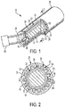
FIG. 1 is a perspective, partial sectional view of an overheat bleed air detector; -
FIG. 2 is a cross-sectional view of the overheat bleed air detector along line 2-2; and -
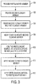
FIG. 3 is a flowchart of a method of manufacturing an overheat bleed air detector. - Referring now to the Figures, where the present disclosure will be described with reference to specific embodiments, without limiting same, it is to be understood that the disclosed embodiments are merely illustrative of the present disclosure that may be embodied in various and alternative forms. Various elements of the disclosed embodiments may be combined or omitted to form further embodiments of the present disclosure. The figures are not necessarily to scale; some features may be exaggerated or minimized to show details of particular components. Therefore, specific structural and functional details disclosed herein are not to be interpreted as limiting, but merely as a representative basis for teaching one skilled in the art to variously employ the present disclosure.
- Referring to
Fig. 1 , a thermal sensor or overheatbleed air detector 10 is shown. The overheat bleedair detector 10 is configured to monitor or detect a temperature of bleed air greater than a threshold temperature that is provided to an aircraft environmental control system from an engine. The overheat bleedair detector 10 includes a firstelongate member 20, a secondelongate member 22, astate changing material 24, and acenter wire 26. - The first
elongate member 20 is configured as an outer electrode. The firstelongate member 20 has a firstelongate member body 30 having aninner surface 32 disposed opposite anouter surface 34. Theinner surface 32 and theouter surface 34 of the firstelongate member body 30 extend between a first elongate memberfirst end 36 and a first elongate membersecond end 38. The firstelongate member body 30 is a generally cylindrical or tubular body. - Referring to
Figs. 1 and 2 , theinner surface 32 defines an inner bore of the firstelongate member 20. Theinner surface 32 defines a plurality ofgrooves 50. In at least one embodiment, the plurality ofgrooves 50 may be configured as at least one groove. The plurality ofgrooves 50 extend from the first elongate member firstend 36 towards the first elongate membersecond end 38. The plurality ofgrooves 50 define and separate a plurality offins 52. In at least one embodiment, the at least one groove defines and separates at least one fin. - Each
fin 54 of the plurality offins 52 defines afirst side surface 60, asecond side surface 62, and atip 64 that extends between thefirst side surface 60 and thesecond side surface 62. Thefirst side surface 60 is disposed in a non-parallel relationship with thesecond side surface 62. In at least one embodiment, thefirst side surface 60 becomes progressively closer to thesecond side surface 62 in a direction that extends from a base of thefin 54 towards thetip 64 of thefin 54. In at least one embodiment, thetip 64 is substantially rounded. - The second
elongate member 22 is received within the inner bore of the firstelongate member 20. The secondelongate member 22 has a secondelongate member body 70 having aninner surface 72 disposed opposite anouter surface 74. Theinner surface 72 and theouter surface 74 of the secondelongate member body 70 extend between a second elongate memberfirst end 76 and a second elongate membersecond end 78. The secondelongate member body 70 is a generally cylindrical or tubular body. - The
outer surface 74 of the secondelongate member body 70 is spaced apart from and does not engage theinner surface 32 of the firstelongate member body 30. Thetip 64 of eachfin 54 is spaced apart from and does not engage theouter surface 74 of the secondelongate member body 70. - The second
elongate member 22 is configured as a ceramic based insert. In at least one embodiment, the secondelongate member 22 is a porous ceramic or glass. The porous ceramic includes non-conducting metal oxides such as alumina or glass. The porous ceramic may include glass fibers or any other suitable porous ceramic in membrane form. - The
state changing material 24 is disposed between theinner surface 32 of the firstelongate member body 30 of the firstelongate member 20 and theouter surface 74 of the secondelongate member body 70 of the secondelongate member 22. Thestate changing material 24 engages theinner surface 32 of the firstelongate member body 30 of the firstelongate member 20 and theouter surface 74 of the secondelongate member body 70 of the secondelongate member 22. Thestate changing material 24 is disposed between and engagesadjacent fins 54 of the plurality offins 52 defined by the plurality ofgrooves 50 of theinner surface 32 of the firstelongate member body 30 of the firstelongate member 20. - The
state changing material 24 is inserted between theinner surface 32 of the firstelongate member body 30 of the firstelongate member 20 and theouter surface 74 of the secondelongate member body 70 of the secondelongate member 22 while in a molten or liquid state. In at least one embodiment, thestate changing material 24 impregnates theouter surface 74 of the secondelongate member body 70 of the secondelongate member 22. Thestate changing material 24 flows through a fill path defined by theouter surface 74 of the secondelongate member body 70 of the secondelongate member 22 and the plurality offins 52 defined by the plurality ofgrooves 50 of theinner surface 32 of the firstelongate member body 30 of the firstelongate member 20. The fins of the plurality offins 52, defined by the plurality ofgrooves 50, aid in the fluid flow of thestate changing material 24 through the fill path. - The
state changing material 24 may be a eutectic salt, a salt mixture, a conducting polymer film, or other phase changing material. The salts may include lithium, sodium, or potassium cations. Thestate changing material 24 is selected to provide a melting point temperature at a desired threshold temperature, i.e. 99°C or above, indicative of an overheated bleed air. Thestate changing material 24 is configured to be non-conductive when in a solid state and is configured to be conductive when in a semi-solid or liquid state. - The
center wire 26 is received within a bore defined by theinner surface 72 of the secondelongate member body 70 of the secondelongate member 22. Thecenter wire 26 is configured as an inner electrode. Thecenter wire 26 is electrically connected to acontroller 90. Thecontroller 90 is configured to measure or determine an impedance, resistance, voltage, current, or other electrical characteristic of the overheatbleed air detector 10. The measured electrical characteristic indicates whether the bleed air temperature is greater than or less than a threshold temperature. - The overheat
bleed air detector 10 is disposed within or as in thermal communication with a duct that carries bleed air from the engine to the environmental control system. Responsive to a temperature of the bleed air less than a temperature threshold of thestate changing material 24, thestate changing material 24 remains in a solid state and a non-conductive state. The circuit created by the firstelongate member 20 and the secondelongate member 22 and thecontroller 90 remains open. Responsive to a temperature of the bleed air greater than the temperature threshold of thestate changing material 24, thestate changing material 24 melts and is in a conductive state. The circuit created by the firstelongate member 20 and the secondelongate member 22 and thecontroller 90 closes. Thecontroller 90 sends a signal indicative of bleed air overheat condition or a bleed air temperature exceeding the temperature threshold. - During manufacturing of the overheat
bleed air detector 10, the combination of the firstelongate member 20 and the secondelongate member 22 are coiled. The coiling of the firstelongate member 20 and the secondelongate member 22 may result in breaking or fracturing of the secondelongate member 22. The break or fracture of the secondelongate member 22 may create a non-uniform cross-section for the flow of the molten or liquidstate changing material 24. The plurality offins 52 defined by the plurality ofgrooves 50 defined by theinner surface 32 of the firstelongate member body 30 improves the flow of the molten or liquidstate changing material 24 and provides a substantially uniform or substantially homogeneous flow of the molten or liquidstate changing material 24 between the firstelongate member 20 and the secondelongate member 22. A height of each fin of the plurality offins 52 defined by the plurality ofgrooves 50 is sized to inhibit obstruction of the fill path by the breaking or fracturing of the secondelongate member 22 during coiling. - The at least one fin or the plurality of
fins 52 defined by the at least one groove or the plurality ofgrooves 50 improve detection of an overheat condition of the bleed air. The presence of the plurality offins 52 improves heat transfer to thestate changing material 24, i.e. improves/increases the heat transfer coefficient or increases/improves the heat transfer rate of the firstelongate member 20 to allow for faster detection of the overheat condition, improving the overall detection performance of the overheatbleed air detector 10. - Referring to
Fig. 3 , a flowchart of a method of manufacturing the overheatbleed air detector 10 is shown. Atblock 100, the firstelongate member 20 is provided. Atblock 102, the secondelongate member 22 is provided. Atblock 104, the secondelongate member 22 is inserted within the firstelongate member 20. Atblock 106, thecenter wire 26 is inserted within the secondelongate member 22. Thecenter wire 26 is disposed concentric with the secondelongate member 22 and the firstelongate member 20. - At
block 108 the combination of the firstelongate member 20, the secondelongate member 22, and acenter wire 26 are coiled using the coiling apparatus. At block 110 a vacuum is applied to thesecond end 38 of the firstelongate member 20. Atblock 112, thestate changing material 24 is applied to thefirst end 36 of the firstelongate member 20. Thestate changing material 24 is applied between theinner surface 32 of the firstelongate member 20 and theouter surface 74 of the secondelongate member 22. - The
state changing material 24 is applied in a molten or liquid state. The vacuum applied to thesecond end 36 of the firstelongate member 20 in conjunction with the plurality offins 52 defined by the plurality ofgrooves 50 defined by theinner surface 32 of the firstelongate member body 30 of the firstelongate member 20 encourages or aids the molten or liquidstate changing material 24 to flow from thefirst end 36 of the firstelongate member 20 towards thesecond end 38 of the firstelongate member 20 through the fill path. Atblock 110, the molten or liquidstate changing material 24 is solidified to form the overheatbleed air detector 10. - While the present disclosure has been described in detail in connection with only a limited number of embodiments, it should be readily understood that the present disclosure is not limited to such disclosed embodiments. Rather, the present disclosure can be modified to incorporate any number of variations, alterations, substitutions or equivalent arrangements not heretofore described, but which are commensurate with the scope of the present disclosure. Additionally, while various embodiments of the present disclosure have been described, it is to be understood that aspects of the present disclosure may include only some of the described embodiments. Accordingly, the present disclosure is not to be seen as limited by the foregoing description, but is only limited by the scope of the appended claims.
Claims (15)
- An overheat bleed air detector (10), comprising:a first elongate member (20) having a first elongate member body (30) extending between a first elongate member first end (36) and a first elongate member second end (38), the first elongate member body (30) having an inner surface (32) defining at least one groove (50) that extends from the first elongate member first end (36) towards the first elongate member second end (38); anda second elongate member (22) received within the first elongate member (20), the second elongate member (22) having a second elongate member body (70) extending between a second elongate member first end (76) and a second elongate member second end (78), the second elongate member body (70) having an outer surface (74) spaced apart from the inner surface (32).
- The overheat bleed air detector of claim 1, further comprising a state changing material (24) disposed between the first elongate member (20) and the second elongate member (22).
- The overheat bleed air detector of claim 1 or 2, further comprising a center wire (26) received within the second elongate member (22).
- The overheat bleed air detector of claim 1, 2 or 3, wherein the at least one groove (50) is configured as a plurality of grooves (50) that define at least one fin (52) that extends from the inner surface (32) towards the second elongate member (22).
- The overheat bleed air detector of claim 4, wherein the at least one fin (52) improves a heat transfer coefficient of the first elongate member (20).
- The overheat bleed air detector of claim 4 or 5, wherein the at least one fin (52) includes a first side surface (60) and a second side surface (62) and a tip (64) extending between the first side surface (60) and the second side surface (62).
- The overheat bleed air detector of claim 6, wherein the first side surface (60) is disposed in a non-parallel relationship with the second side surface (62).
- The overheat bleed air detector of claim 6 or 7, wherein the tip (64) is spaced apart from the outer surface (74) of the second elongate member (22).
- The overheat bleed air detector of claim 6, 7 or 8, wherein the tip (64) is rounded.
- The overheat bleed air detector of any of claims 4 to 9, wherein a or the state changing material (24) is disposed between adjacent grooves (50) of the plurality of grooves (50).
- The overheat bleed air detector of any preceding claim, wherein the second elongate member (22) is configured as a ceramic based insert.
- A method of manufacturing an overheat bleed air detector (10), comprising:providing a first elongate member (20) having an inner surface (32) defining a plurality of grooves (50) that extend from a first elongate member first end (36) towards a first elongate member second end (38);providing a second elongate member (22) made of a ceramic based material;inserting the second elongate member (22) within the first elongate member (20), such that an outer surface (74) of the second elongate member (22) is spaced apart from the inner surface (32) of the first elongate member (20); andinserting a center wire (26) within the second elongate member (22).
- The method of claim 12, further comprising:applying a vacuum to the second end (38) of the first elongate member (20); andapplying a state changing material (24) at the first end (36) of the first elongate member (20), between the first elongate member (20) and the second elongate member (22) to impregnate the second elongate member (22) with the state changing material (24).
- The method of claim 12 or 13, wherein the plurality of grooves (50) define a fill path for the state changing material (24).
- The method of claim 12, 13 or 14, wherein the plurality of grooves (50) define and separate a plurality of fins (52) that extend from the inner surface (32) towards the second elongate member (22).
Applications Claiming Priority (1)
| Application Number | Priority Date | Filing Date | Title |
|---|---|---|---|
| US15/072,941 US10240985B2 (en) | 2016-03-17 | 2016-03-17 | Overheat bleed air detector and method of manufacture |
Publications (2)
| Publication Number | Publication Date |
|---|---|
| EP3220114A1 true EP3220114A1 (en) | 2017-09-20 |
| EP3220114B1 EP3220114B1 (en) | 2019-01-02 |
Family
ID=58387707
Family Applications (1)
| Application Number | Title | Priority Date | Filing Date |
|---|---|---|---|
| EP17161689.9A Active EP3220114B1 (en) | 2016-03-17 | 2017-03-17 | Overheat bleed air detector and method of manufacture |
Country Status (3)
| Country | Link |
|---|---|
| US (1) | US10240985B2 (en) |
| EP (1) | EP3220114B1 (en) |
| CA (1) | CA2961319C (en) |
Cited By (1)
| Publication number | Priority date | Publication date | Assignee | Title |
|---|---|---|---|---|
| EP3778399A1 (en) * | 2019-08-16 | 2021-02-17 | Kidde Technologies, Inc. | Thermal sensor and method of manufacture |
Families Citing this family (1)
| Publication number | Priority date | Publication date | Assignee | Title |
|---|---|---|---|---|
| US11879787B2 (en) * | 2020-10-06 | 2024-01-23 | Kidde Technologies, Inc. | Heat sensor cable with ceramic coil and eutectic salt between inner and outer conductors |
Citations (3)
| Publication number | Priority date | Publication date | Assignee | Title |
|---|---|---|---|---|
| US3682130A (en) * | 1965-03-19 | 1972-08-08 | Jeffers & Bailey Inc | Fusible temperature responsive trigger device |
| EP1645856A1 (en) * | 2004-10-06 | 2006-04-12 | 3M Innovative Properties Company | Microstructured time dependent indicators |
| EP2957877A1 (en) * | 2014-06-18 | 2015-12-23 | Kidde Technologies, Inc. | Thermal sensor |
Family Cites Families (8)
| Publication number | Priority date | Publication date | Assignee | Title |
|---|---|---|---|---|
| US2236286A (en) * | 1941-03-25 | Electbic cable | ||
| US2050991A (en) * | 1930-06-14 | 1936-08-11 | Gen Cable Corp | Cable and method of making |
| AT309851B (en) * | 1969-11-04 | 1973-09-10 | Thermo Bauelement Ag | Temperature switch |
| JPS56158313A (en) | 1980-05-12 | 1981-12-07 | Kokusai Denshin Denwa Co Ltd <Kdd> | Sealing structure at lead-in part of optical fiber cable |
| CA1231825A (en) | 1984-05-23 | 1988-01-26 | Sadayuki Dannoura | Die-casting apparatus |
| FR2600000B1 (en) | 1986-06-13 | 1989-04-14 | Extramet Sa | PROCESS AND DEVICE FOR GRANULATING A MOLTEN METAL |
| JP4454948B2 (en) * | 2002-04-12 | 2010-04-21 | 株式会社東芝 | Non-aqueous electrolyte secondary battery |
| US8356935B2 (en) * | 2009-10-09 | 2013-01-22 | Shell Oil Company | Methods for assessing a temperature in a subsurface formation |
-
2016
- 2016-03-17 US US15/072,941 patent/US10240985B2/en active Active
-
2017
- 2017-03-16 CA CA2961319A patent/CA2961319C/en active Active
- 2017-03-17 EP EP17161689.9A patent/EP3220114B1/en active Active
Patent Citations (3)
| Publication number | Priority date | Publication date | Assignee | Title |
|---|---|---|---|---|
| US3682130A (en) * | 1965-03-19 | 1972-08-08 | Jeffers & Bailey Inc | Fusible temperature responsive trigger device |
| EP1645856A1 (en) * | 2004-10-06 | 2006-04-12 | 3M Innovative Properties Company | Microstructured time dependent indicators |
| EP2957877A1 (en) * | 2014-06-18 | 2015-12-23 | Kidde Technologies, Inc. | Thermal sensor |
Cited By (2)
| Publication number | Priority date | Publication date | Assignee | Title |
|---|---|---|---|---|
| EP3778399A1 (en) * | 2019-08-16 | 2021-02-17 | Kidde Technologies, Inc. | Thermal sensor and method of manufacture |
| US11408780B2 (en) | 2019-08-16 | 2022-08-09 | Kidde Technologies, Inc. | Thermal sensor and method of manufacture |
Also Published As
| Publication number | Publication date |
|---|---|
| EP3220114B1 (en) | 2019-01-02 |
| US20170268933A1 (en) | 2017-09-21 |
| CA2961319A1 (en) | 2017-09-17 |
| CA2961319C (en) | 2024-04-09 |
| US10240985B2 (en) | 2019-03-26 |
Similar Documents
| Publication | Publication Date | Title |
|---|---|---|
| EP2957877B1 (en) | Thermal sensor and method of manufacturing thereof | |
| EP3009847B1 (en) | One-piece air data probe | |
| EP3220114B1 (en) | Overheat bleed air detector and method of manufacture | |
| KR20180014053A (en) | Resistive heater with temperature sensing power pins | |
| EP3009818B1 (en) | Thermal sensor | |
| US20150069999A1 (en) | Method for Contacting at least Two Metal Electrodes and Arrangement | |
| US10539471B2 (en) | Thermal sensor | |
| EP1777503B1 (en) | Temperature switch | |
| CN100504322C (en) | An alarm method for linear temperature-sensitive detectors | |
| CN205722275U (en) | Beyond-retrieve-type cable-type line-type heat fire detector | |
| EP3761283B1 (en) | Shape memory alloy actuated fire and overheat detector | |
| EP4417423A1 (en) | Additively manufactured detectors | |
| WO2008046249A1 (en) | A nonrenewable linear temperature-sensing detector with alarm about short-circuit trouble | |
| JP2007078433A (en) | Polyimide-coated sheath thermocouple | |
| US10113918B2 (en) | Arrangement of a sensor for measuring the temperature of a medium in a motor vehicle | |
| CN115131936A (en) | Temperature sensing cable and fire alarm system | |
| CN103345810A (en) | Temperature sensing cable for fire protection | |
| CN1996411A (en) | Linear temperature sensing element equipped with fused insulating layer and pressure-sensitive rubber layer | |
| CN107850566A (en) | Device for detecting at least one property of a medium and method for regulating a signal of the device |
Legal Events
| Date | Code | Title | Description |
|---|---|---|---|
| PUAI | Public reference made under article 153(3) epc to a published international application that has entered the european phase |
Free format text: ORIGINAL CODE: 0009012 |
|
| STAA | Information on the status of an ep patent application or granted ep patent |
Free format text: STATUS: THE APPLICATION HAS BEEN PUBLISHED |
|
| AK | Designated contracting states |
Kind code of ref document: A1 Designated state(s): AL AT BE BG CH CY CZ DE DK EE ES FI FR GB GR HR HU IE IS IT LI LT LU LV MC MK MT NL NO PL PT RO RS SE SI SK SM TR |
|
| AX | Request for extension of the european patent |
Extension state: BA ME |
|
| STAA | Information on the status of an ep patent application or granted ep patent |
Free format text: STATUS: REQUEST FOR EXAMINATION WAS MADE |
|
| 17P | Request for examination filed |
Effective date: 20180320 |
|
| RBV | Designated contracting states (corrected) |
Designated state(s): AL AT BE BG CH CY CZ DE DK EE ES FI FR GB GR HR HU IE IS IT LI LT LU LV MC MK MT NL NO PL PT RO RS SE SI SK SM TR |
|
| GRAP | Despatch of communication of intention to grant a patent |
Free format text: ORIGINAL CODE: EPIDOSNIGR1 |
|
| STAA | Information on the status of an ep patent application or granted ep patent |
Free format text: STATUS: GRANT OF PATENT IS INTENDED |
|
| RIC1 | Information provided on ipc code assigned before grant |
Ipc: G01K 11/06 20060101ALI20180524BHEP Ipc: G01K 3/00 20060101AFI20180524BHEP |
|
| INTG | Intention to grant announced |
Effective date: 20180607 |
|
| GRAS | Grant fee paid |
Free format text: ORIGINAL CODE: EPIDOSNIGR3 |
|
| GRAA | (expected) grant |
Free format text: ORIGINAL CODE: 0009210 |
|
| STAA | Information on the status of an ep patent application or granted ep patent |
Free format text: STATUS: THE PATENT HAS BEEN GRANTED |
|
| AK | Designated contracting states |
Kind code of ref document: B1 Designated state(s): AL AT BE BG CH CY CZ DE DK EE ES FI FR GB GR HR HU IE IS IT LI LT LU LV MC MK MT NL NO PL PT RO RS SE SI SK SM TR |
|
| REG | Reference to a national code |
Ref country code: GB Ref legal event code: FG4D |
|
| REG | Reference to a national code |
Ref country code: CH Ref legal event code: EP Ref country code: AT Ref legal event code: REF Ref document number: 1084982 Country of ref document: AT Kind code of ref document: T Effective date: 20190115 |
|
| REG | Reference to a national code |
Ref country code: IE Ref legal event code: FG4D |
|
| REG | Reference to a national code |
Ref country code: DE Ref legal event code: R096 Ref document number: 602017001619 Country of ref document: DE |
|
| REG | Reference to a national code |
Ref country code: NL Ref legal event code: MP Effective date: 20190102 |
|
| REG | Reference to a national code |
Ref country code: LT Ref legal event code: MG4D |
|
| REG | Reference to a national code |
Ref country code: AT Ref legal event code: MK05 Ref document number: 1084982 Country of ref document: AT Kind code of ref document: T Effective date: 20190102 |
|
| PG25 | Lapsed in a contracting state [announced via postgrant information from national office to epo] |
Ref country code: NL Free format text: LAPSE BECAUSE OF FAILURE TO SUBMIT A TRANSLATION OF THE DESCRIPTION OR TO PAY THE FEE WITHIN THE PRESCRIBED TIME-LIMIT Effective date: 20190102 |
|
| PG25 | Lapsed in a contracting state [announced via postgrant information from national office to epo] |
Ref country code: ES Free format text: LAPSE BECAUSE OF FAILURE TO SUBMIT A TRANSLATION OF THE DESCRIPTION OR TO PAY THE FEE WITHIN THE PRESCRIBED TIME-LIMIT Effective date: 20190102 Ref country code: PT Free format text: LAPSE BECAUSE OF FAILURE TO SUBMIT A TRANSLATION OF THE DESCRIPTION OR TO PAY THE FEE WITHIN THE PRESCRIBED TIME-LIMIT Effective date: 20190502 Ref country code: SE Free format text: LAPSE BECAUSE OF FAILURE TO SUBMIT A TRANSLATION OF THE DESCRIPTION OR TO PAY THE FEE WITHIN THE PRESCRIBED TIME-LIMIT Effective date: 20190102 Ref country code: FI Free format text: LAPSE BECAUSE OF FAILURE TO SUBMIT A TRANSLATION OF THE DESCRIPTION OR TO PAY THE FEE WITHIN THE PRESCRIBED TIME-LIMIT Effective date: 20190102 Ref country code: NO Free format text: LAPSE BECAUSE OF FAILURE TO SUBMIT A TRANSLATION OF THE DESCRIPTION OR TO PAY THE FEE WITHIN THE PRESCRIBED TIME-LIMIT Effective date: 20190402 Ref country code: PL Free format text: LAPSE BECAUSE OF FAILURE TO SUBMIT A TRANSLATION OF THE DESCRIPTION OR TO PAY THE FEE WITHIN THE PRESCRIBED TIME-LIMIT Effective date: 20190102 Ref country code: LT Free format text: LAPSE BECAUSE OF FAILURE TO SUBMIT A TRANSLATION OF THE DESCRIPTION OR TO PAY THE FEE WITHIN THE PRESCRIBED TIME-LIMIT Effective date: 20190102 |
|
| PG25 | Lapsed in a contracting state [announced via postgrant information from national office to epo] |
Ref country code: IS Free format text: LAPSE BECAUSE OF FAILURE TO SUBMIT A TRANSLATION OF THE DESCRIPTION OR TO PAY THE FEE WITHIN THE PRESCRIBED TIME-LIMIT Effective date: 20190502 Ref country code: BG Free format text: LAPSE BECAUSE OF FAILURE TO SUBMIT A TRANSLATION OF THE DESCRIPTION OR TO PAY THE FEE WITHIN THE PRESCRIBED TIME-LIMIT Effective date: 20190402 Ref country code: HR Free format text: LAPSE BECAUSE OF FAILURE TO SUBMIT A TRANSLATION OF THE DESCRIPTION OR TO PAY THE FEE WITHIN THE PRESCRIBED TIME-LIMIT Effective date: 20190102 Ref country code: GR Free format text: LAPSE BECAUSE OF FAILURE TO SUBMIT A TRANSLATION OF THE DESCRIPTION OR TO PAY THE FEE WITHIN THE PRESCRIBED TIME-LIMIT Effective date: 20190403 Ref country code: LV Free format text: LAPSE BECAUSE OF FAILURE TO SUBMIT A TRANSLATION OF THE DESCRIPTION OR TO PAY THE FEE WITHIN THE PRESCRIBED TIME-LIMIT Effective date: 20190102 Ref country code: RS Free format text: LAPSE BECAUSE OF FAILURE TO SUBMIT A TRANSLATION OF THE DESCRIPTION OR TO PAY THE FEE WITHIN THE PRESCRIBED TIME-LIMIT Effective date: 20190102 |
|
| REG | Reference to a national code |
Ref country code: DE Ref legal event code: R097 Ref document number: 602017001619 Country of ref document: DE |
|
| PG25 | Lapsed in a contracting state [announced via postgrant information from national office to epo] |
Ref country code: CZ Free format text: LAPSE BECAUSE OF FAILURE TO SUBMIT A TRANSLATION OF THE DESCRIPTION OR TO PAY THE FEE WITHIN THE PRESCRIBED TIME-LIMIT Effective date: 20190102 Ref country code: IT Free format text: LAPSE BECAUSE OF FAILURE TO SUBMIT A TRANSLATION OF THE DESCRIPTION OR TO PAY THE FEE WITHIN THE PRESCRIBED TIME-LIMIT Effective date: 20190102 Ref country code: RO Free format text: LAPSE BECAUSE OF FAILURE TO SUBMIT A TRANSLATION OF THE DESCRIPTION OR TO PAY THE FEE WITHIN THE PRESCRIBED TIME-LIMIT Effective date: 20190102 Ref country code: DK Free format text: LAPSE BECAUSE OF FAILURE TO SUBMIT A TRANSLATION OF THE DESCRIPTION OR TO PAY THE FEE WITHIN THE PRESCRIBED TIME-LIMIT Effective date: 20190102 Ref country code: AT Free format text: LAPSE BECAUSE OF FAILURE TO SUBMIT A TRANSLATION OF THE DESCRIPTION OR TO PAY THE FEE WITHIN THE PRESCRIBED TIME-LIMIT Effective date: 20190102 Ref country code: EE Free format text: LAPSE BECAUSE OF FAILURE TO SUBMIT A TRANSLATION OF THE DESCRIPTION OR TO PAY THE FEE WITHIN THE PRESCRIBED TIME-LIMIT Effective date: 20190102 Ref country code: MC Free format text: LAPSE BECAUSE OF FAILURE TO SUBMIT A TRANSLATION OF THE DESCRIPTION OR TO PAY THE FEE WITHIN THE PRESCRIBED TIME-LIMIT Effective date: 20190102 Ref country code: SK Free format text: LAPSE BECAUSE OF FAILURE TO SUBMIT A TRANSLATION OF THE DESCRIPTION OR TO PAY THE FEE WITHIN THE PRESCRIBED TIME-LIMIT Effective date: 20190102 Ref country code: AL Free format text: LAPSE BECAUSE OF FAILURE TO SUBMIT A TRANSLATION OF THE DESCRIPTION OR TO PAY THE FEE WITHIN THE PRESCRIBED TIME-LIMIT Effective date: 20190102 |
|
| PLBE | No opposition filed within time limit |
Free format text: ORIGINAL CODE: 0009261 |
|
| STAA | Information on the status of an ep patent application or granted ep patent |
Free format text: STATUS: NO OPPOSITION FILED WITHIN TIME LIMIT |
|
| PG25 | Lapsed in a contracting state [announced via postgrant information from national office to epo] |
Ref country code: LU Free format text: LAPSE BECAUSE OF NON-PAYMENT OF DUE FEES Effective date: 20190317 Ref country code: SM Free format text: LAPSE BECAUSE OF FAILURE TO SUBMIT A TRANSLATION OF THE DESCRIPTION OR TO PAY THE FEE WITHIN THE PRESCRIBED TIME-LIMIT Effective date: 20190102 |
|
| 26N | No opposition filed |
Effective date: 20191003 |
|
| REG | Reference to a national code |
Ref country code: BE Ref legal event code: MM Effective date: 20190331 |
|
| PG25 | Lapsed in a contracting state [announced via postgrant information from national office to epo] |
Ref country code: IE Free format text: LAPSE BECAUSE OF NON-PAYMENT OF DUE FEES Effective date: 20190317 |
|
| PG25 | Lapsed in a contracting state [announced via postgrant information from national office to epo] |
Ref country code: SI Free format text: LAPSE BECAUSE OF FAILURE TO SUBMIT A TRANSLATION OF THE DESCRIPTION OR TO PAY THE FEE WITHIN THE PRESCRIBED TIME-LIMIT Effective date: 20190102 Ref country code: BE Free format text: LAPSE BECAUSE OF NON-PAYMENT OF DUE FEES Effective date: 20190331 |
|
| PG25 | Lapsed in a contracting state [announced via postgrant information from national office to epo] |
Ref country code: TR Free format text: LAPSE BECAUSE OF FAILURE TO SUBMIT A TRANSLATION OF THE DESCRIPTION OR TO PAY THE FEE WITHIN THE PRESCRIBED TIME-LIMIT Effective date: 20190102 |
|
| PG25 | Lapsed in a contracting state [announced via postgrant information from national office to epo] |
Ref country code: MT Free format text: LAPSE BECAUSE OF NON-PAYMENT OF DUE FEES Effective date: 20190317 |
|
| REG | Reference to a national code |
Ref country code: CH Ref legal event code: PL |
|
| PG25 | Lapsed in a contracting state [announced via postgrant information from national office to epo] |
Ref country code: CH Free format text: LAPSE BECAUSE OF NON-PAYMENT OF DUE FEES Effective date: 20200331 Ref country code: LI Free format text: LAPSE BECAUSE OF NON-PAYMENT OF DUE FEES Effective date: 20200331 |
|
| PG25 | Lapsed in a contracting state [announced via postgrant information from national office to epo] |
Ref country code: CY Free format text: LAPSE BECAUSE OF FAILURE TO SUBMIT A TRANSLATION OF THE DESCRIPTION OR TO PAY THE FEE WITHIN THE PRESCRIBED TIME-LIMIT Effective date: 20190102 |
|
| PG25 | Lapsed in a contracting state [announced via postgrant information from national office to epo] |
Ref country code: HU Free format text: LAPSE BECAUSE OF FAILURE TO SUBMIT A TRANSLATION OF THE DESCRIPTION OR TO PAY THE FEE WITHIN THE PRESCRIBED TIME-LIMIT; INVALID AB INITIO Effective date: 20170317 |
|
| PG25 | Lapsed in a contracting state [announced via postgrant information from national office to epo] |
Ref country code: MK Free format text: LAPSE BECAUSE OF FAILURE TO SUBMIT A TRANSLATION OF THE DESCRIPTION OR TO PAY THE FEE WITHIN THE PRESCRIBED TIME-LIMIT Effective date: 20190102 |
|
| P01 | Opt-out of the competence of the unified patent court (upc) registered |
Effective date: 20230603 |
|
| PGFP | Annual fee paid to national office [announced via postgrant information from national office to epo] |
Ref country code: GB Payment date: 20260220 Year of fee payment: 10 |
|
| PGFP | Annual fee paid to national office [announced via postgrant information from national office to epo] |
Ref country code: DE Payment date: 20260219 Year of fee payment: 10 |
|
| PGFP | Annual fee paid to national office [announced via postgrant information from national office to epo] |
Ref country code: FR Payment date: 20260219 Year of fee payment: 10 |