EP3220092A1 - Bent pipe and a semiconductor refrigeration refrigerator with bent pipe - Google Patents
Bent pipe and a semiconductor refrigeration refrigerator with bent pipe Download PDFInfo
- Publication number
- EP3220092A1 EP3220092A1 EP15869101.4A EP15869101A EP3220092A1 EP 3220092 A1 EP3220092 A1 EP 3220092A1 EP 15869101 A EP15869101 A EP 15869101A EP 3220092 A1 EP3220092 A1 EP 3220092A1
- Authority
- EP
- European Patent Office
- Prior art keywords
- bent pipe
- bent
- pipe
- retention member
- refrigerant
- Prior art date
- Legal status (The legal status is an assumption and is not a legal conclusion. Google has not performed a legal analysis and makes no representation as to the accuracy of the status listed.)
- Granted
Links
Images




Classifications
-
- F—MECHANICAL ENGINEERING; LIGHTING; HEATING; WEAPONS; BLASTING
- F25—REFRIGERATION OR COOLING; COMBINED HEATING AND REFRIGERATION SYSTEMS; HEAT PUMP SYSTEMS; MANUFACTURE OR STORAGE OF ICE; LIQUEFACTION SOLIDIFICATION OF GASES
- F25B—REFRIGERATION MACHINES, PLANTS OR SYSTEMS; COMBINED HEATING AND REFRIGERATION SYSTEMS; HEAT PUMP SYSTEMS
- F25B21/00—Machines, plants or systems, using electric or magnetic effects
- F25B21/02—Machines, plants or systems, using electric or magnetic effects using Peltier effect; using Nernst-Ettinghausen effect
-
- F—MECHANICAL ENGINEERING; LIGHTING; HEATING; WEAPONS; BLASTING
- F25—REFRIGERATION OR COOLING; COMBINED HEATING AND REFRIGERATION SYSTEMS; HEAT PUMP SYSTEMS; MANUFACTURE OR STORAGE OF ICE; LIQUEFACTION SOLIDIFICATION OF GASES
- F25D—REFRIGERATORS; COLD ROOMS; ICE-BOXES; COOLING OR FREEZING APPARATUS NOT OTHERWISE PROVIDED FOR
- F25D16/00—Devices using a combination of a cooling mode associated with refrigerating machinery with a cooling mode not associated with refrigerating machinery
-
- F—MECHANICAL ENGINEERING; LIGHTING; HEATING; WEAPONS; BLASTING
- F25—REFRIGERATION OR COOLING; COMBINED HEATING AND REFRIGERATION SYSTEMS; HEAT PUMP SYSTEMS; MANUFACTURE OR STORAGE OF ICE; LIQUEFACTION SOLIDIFICATION OF GASES
- F25D—REFRIGERATORS; COLD ROOMS; ICE-BOXES; COOLING OR FREEZING APPARATUS NOT OTHERWISE PROVIDED FOR
- F25D19/00—Arrangement or mounting of refrigeration units with respect to devices or objects to be refrigerated, e.g. infrared detectors
-
- F—MECHANICAL ENGINEERING; LIGHTING; HEATING; WEAPONS; BLASTING
- F25—REFRIGERATION OR COOLING; COMBINED HEATING AND REFRIGERATION SYSTEMS; HEAT PUMP SYSTEMS; MANUFACTURE OR STORAGE OF ICE; LIQUEFACTION SOLIDIFICATION OF GASES
- F25D—REFRIGERATORS; COLD ROOMS; ICE-BOXES; COOLING OR FREEZING APPARATUS NOT OTHERWISE PROVIDED FOR
- F25D23/00—General constructional features
- F25D23/006—General constructional features for mounting refrigerating machinery components
-
- F—MECHANICAL ENGINEERING; LIGHTING; HEATING; WEAPONS; BLASTING
- F25—REFRIGERATION OR COOLING; COMBINED HEATING AND REFRIGERATION SYSTEMS; HEAT PUMP SYSTEMS; MANUFACTURE OR STORAGE OF ICE; LIQUEFACTION SOLIDIFICATION OF GASES
- F25D—REFRIGERATORS; COLD ROOMS; ICE-BOXES; COOLING OR FREEZING APPARATUS NOT OTHERWISE PROVIDED FOR
- F25D23/00—General constructional features
- F25D23/06—Walls
- F25D23/065—Details
- F25D23/066—Liners
-
- F—MECHANICAL ENGINEERING; LIGHTING; HEATING; WEAPONS; BLASTING
- F28—HEAT EXCHANGE IN GENERAL
- F28D—HEAT-EXCHANGE APPARATUS, NOT PROVIDED FOR IN ANOTHER SUBCLASS, IN WHICH THE HEAT-EXCHANGE MEDIA DO NOT COME INTO DIRECT CONTACT
- F28D15/00—Heat-exchange apparatus with the intermediate heat-transfer medium in closed tubes passing into or through the conduit walls ; Heat-exchange apparatus employing intermediate heat-transfer medium or bodies
- F28D15/02—Heat-exchange apparatus with the intermediate heat-transfer medium in closed tubes passing into or through the conduit walls ; Heat-exchange apparatus employing intermediate heat-transfer medium or bodies in which the medium condenses and evaporates, e.g. heat pipes
- F28D15/0233—Heat-exchange apparatus with the intermediate heat-transfer medium in closed tubes passing into or through the conduit walls ; Heat-exchange apparatus employing intermediate heat-transfer medium or bodies in which the medium condenses and evaporates, e.g. heat pipes the conduits having a particular shape, e.g. non-circular cross-section, annular
-
- F—MECHANICAL ENGINEERING; LIGHTING; HEATING; WEAPONS; BLASTING
- F28—HEAT EXCHANGE IN GENERAL
- F28F—DETAILS OF HEAT-EXCHANGE AND HEAT-TRANSFER APPARATUS, OF GENERAL APPLICATION
- F28F9/00—Casings; Header boxes; Auxiliary supports for elements; Auxiliary members within casings
- F28F9/007—Auxiliary supports for elements
- F28F9/013—Auxiliary supports for elements for tubes or tube-assemblies
- F28F9/0132—Auxiliary supports for elements for tubes or tube-assemblies formed by slats, tie-rods, articulated or expandable rods
-
- F—MECHANICAL ENGINEERING; LIGHTING; HEATING; WEAPONS; BLASTING
- F25—REFRIGERATION OR COOLING; COMBINED HEATING AND REFRIGERATION SYSTEMS; HEAT PUMP SYSTEMS; MANUFACTURE OR STORAGE OF ICE; LIQUEFACTION SOLIDIFICATION OF GASES
- F25B—REFRIGERATION MACHINES, PLANTS OR SYSTEMS; COMBINED HEATING AND REFRIGERATION SYSTEMS; HEAT PUMP SYSTEMS
- F25B2321/00—Details of machines, plants or systems, using electric or magnetic effects
- F25B2321/02—Details of machines, plants or systems, using electric or magnetic effects using Peltier effects; using Nernst-Ettinghausen effects
- F25B2321/025—Removal of heat
- F25B2321/0252—Removal of heat by liquids or two-phase fluids
Definitions
- the present invention relates to a refrigeration apparatus and, more particularly, to a bent pipe and a semiconductor refrigerator having the bent pipe.
- a bent pipe may be subjected to a relatively large external force during manufacture, transportation and installation, resulting in deformation of the bent portions of the pipe, thereby changing the bending angle of the entire pipe.
- this is very unfavourable and even totally unacceptable for applications where the bent pipe needs to meet high requirements.
- a heat exchanging device composed of a refrigerant case and a bent pipe is often used to transfer heat from the hot end of a semiconductor cooler to the housing or to transfer cold from the cold end of the semiconductor cooler to a storage compartment of a liner.
- the refrigerant case and the bent pipe are filled with a refrigerant and the refrigerant is allowed to flow therein and undergo phase-change heat exchange, so that the cold from the cold end of the semiconductor cooler is transferred to the liner of the refrigerator, or the heat from hot end of the semiconductor cooler is transferred to the housing of the refrigerator, it has to be ensured that the refrigerant flows in the bent pipe and is effectively evaporated or condensed, which imposes high requirements for the bent pipe.
- An object of a first aspect of the present invention is to overcome at least one defect of the existing bent pipes and is to provide a bent pipe which keeps the bending angle of the bent portion thereof constant.
- Another object of the first aspect of the present invention is to increase the rigidity of the bent pipe.
- An object of a second aspect of the present invention is to provide a semiconductor refrigerator having the aforementioned bent pipe.
- a bent pipe for a fluid to flow therein.
- the bent pipe comprises a plurality of bent portions; a plurality of connecting pipe sections, each connecting two adjacent bent portions; and a retention member, which is successively fixed at different locations along the length thereof to the bent portions on the same side of the bent pipe.
- each of the connecting pipe sections is a straight pipe.
- one end of the bent pipe is an open end and the other end is a closed end.
- the bent pipe further comprises: a further retention member, which is successively fixed at different locations along the length thereof to the bent portions on the other side of the bent pipe.
- the retention member and the further retention member are arranged parallel to each other.
- the retention member is a retention slat or a drawstring.
- the retention member has an elastic modulus of 190 Gpa or more.
- fixing the retention member successively at different locations along the length thereof to the bent portions on the same side of the bent pipe is implemented by welding the retention member successively at different locations along the length thereof to a top hump of each of the bent portions on the same side of the bent pipe.
- pipe walls of the bent pipe that are in contact with the retention member are all fixed to the retention member.
- a semiconductor refrigerator comprising a liner, a semiconductor cooler, a heat exchanging device and a housing, wherein the heat exchanging device is provided with a heat exchanging part which allows a refrigerant to flow therein and undergo phase-change heat exchange and a plurality of refrigerant pipelines with one end connecting to an inner cavity or pipeline of the heat exchanging part for transferring heat from the hot end of the semiconductor cooler to the housing, or transferring cold from the cold end of the semiconductor cooler to a storage compartment of the liner.
- each of the refrigerant pipelines is any of the above bent pipes.
- bent pipe and the semiconductor refrigerator of the present invention have a retention member, at least some of the pipe sections of the bent pipe can be kept in the bent shape such that the bending angle of the bent pipe is kept constant, so that the refrigerant in the semiconductor refrigerator can reliably flow in the bent pipe and can be effectively evaporated or condensed.
- the rigidity of the bent pipe is significantly improved to ensure that the bent portions thereof are not deformed during the manufacture, transportation and installation of the bent pipe.
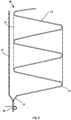
- Fig. 1 is a schematic structural view of a bent pipe 10 according to one embodiment of the present invention.
- an embodiment of the present invention provides a bent pipe 10 for a fluid to flow therein, which bent pipe 10 is particularly suitable for use in a heat exchanging device in a semiconductor refrigerator.
- the bent pipe 10 may comprise a first pipe section having a plurality of bent portions 11 and a plurality of connecting pipe sections 12, and the plurality of connecting pipe sections 12 of the first pipe section are connected to each two adjacent bent portions 11, respectively.
- the bent pipe 10 may include a second pipe section 13 disposed at one end of the first pipe section, and the bent pipe 10 may have only the first pipe section.
- the bent pipe 10 in the embodiment of the present invention further comprises retention member 14, which is successively fixed at different locations along the length thereof, to the bent portions 11 on the same side of the bent pipe 10 such that the bending angle of the bent pipe 10 is kept constant, so that the refrigerant in the semiconductor refrigerator can reliably flow in the bent pipe 10 and can be effectively evaporated or condensed.
- the bent pipe 10 may also include a further retention member 14, which is successively fixed at different locations along the length thereof to the bent portions 11 on the other side of the bent pipe 10.
- Each of the connecting pipe sections 12 is a straight pipe.
- the axes of the connecting pipe sections 12 and the bent portions 11 may be in the same plane.
- the plurality of connecting pipe sections 12 may be arranged at intervals along the lengthwise direction of the retention member 14 and are obliquely arranged at an angle of 10° to 80° with respect to the lengthwise direction of the retention member 14, and each of the bent portions 11 is preferably arranged to be "C"-shaped or arc-shaped, so that the first pipe section of the bent pipe 10 generally exhibits an inclined "Z"-shaped structure.
- Fixing the retention member 14 successively at different locations along the length thereof to the bent portions 11 on the same side of the bent pipe 10 is implemented by welding the retention member 14 successively at different locations along the length thereof to a top hump of each of the bent portions 11 on the same side of the bent pipe 10.
- each bent portion 11 may also be referred to as the outer apex of each bent portion 11.
- the two retention members 14 may be arranged parallel to each other, namely the retention member 14 and the further retention member 14 may be arranged parallel to each other, and the two retention members 14 are respectively fixed on two sides of the first pipe section of the bent pipe 10, and each of the retention member 14 is successively welded at different locations along the length thereof to the top hump of each of the bent portions 11 on the respective side of the first pipe section of the bent pipe 10.
- the pipe walls of the bent pipe 10 that are in contact with the retention member 14 may all be fixed to the retention member 14, that is to say, except that the bent portions 11 of the bent pipe 10 are fixed to the retention member 14, if the pipe walls of the other pipe sections of the bent pipe 10 are in contact with the retention member 14, the pipe walls at this place may also be fixed to the retention member 14 by a fixing process such as welding.
- each bent pipe 10 may be selected from a copper tube, a stainless steel tube, an aluminum tube, etc., preferably a copper tube.
- the retention member 14 has an elastic modulus of 190 GPa or more to ensure the rigidity of the retention member 14, so as to keep at least some of the pipe sections of the bent pipe 10 in a bent shape.
- the retention member 14 may be made of carbon steel or alloy steel.
- the retention member 14 may be a retention slat or drawstring, such as a steel strip, a steel tube or a steel wire rope.
- one end of the bent pipe 10 is an open end and the other end is a closed end, so as to be applied to a heat exchanging device in a semiconductor refrigerator.
- an embodiment of the present invention further provides a heat exchanging device for use in an semiconductor refrigerator.
- the heat exchanging device may be used to transfer the cold from the cold end of the semiconductor cooler to the storage compartment of the liner 100, which may also be referred to as a cold end heat exchanging device 20, which may include a cold end heat exchanging part 21 and a plurality of refrigerant pipelines 22.
- the cold end heat exchanging part 21 defines an inner cavity or pipeline for containing a gas-phase and liquid-phase co-existing refrigerant and and is configured to allow the refrigerant to flow therein and undergo phase-change heat exchange.
- the plurality of refrigerant pipelines 22 are configured to allow the refrigerant to flow therein and undergo phase-change heat exchange.
- Each of the refrigerant pipelines 22 is provided with: an evaporation section which is downwardly bent and extends in a vertical plane and has a closed tail end, and a connection section which is upwardly bent and extends from a starting end of the evaporation section and communicates to the inner cavity or pipeline. That is to say, the first end of each refrigerant pipeline 22 forming the open end communicates to the lower portion of the inner cavity or pipeline, and each refrigerant pipeline 22 obliquely downwardly bent and extends from the first end thereof and terminates at the second end forming the closed end.
- Each of the refrigerant pipelines 22 may be selected as the bent pipe 10 in any of the above embodiments, the first pipe section of the bent pipe 10 is the evaporation section of each of the refrigerant pipeline 22, and the second pipe section 13 of the bent pipe 10 is the connection section of each of the refrigerant pipelines 22.
- the refrigerant poured into the cold end heat exchanging part 21 and the refrigerant pipelines 22 may be carbon dioxide or other refrigeration medium, and the pouring amount of the refrigerant may be measured by a test.
- the cold end heat exchanging part 21 of the cold end heat exchanging device 20 may be a heat exchange copper block in which four stepped blind holes extending in the vertical direction and a horizontal tube hole in communication with the upper portion of each of the step blind holes are provided to form a pipeline inside the cold end heat exchanging part 21.
- the upper end of each of the refrigerant pipelines 22 can be inserted into the corresponding stepped blind hole.
- the cold end heat exchanging device 20 further comprises a refrigerant pouring tube 23 having one end being in communication with the corresponding horizontal tube bore and the other end being operatively open the normally closed end to receive the refrigerant poured from the outside, so as to pour the refrigerant into each of the refrigerant pipelines 22.
- the cold end heat exchanging part 21 of the cold end heat exchanging device 20 may be a cold end heat exchange box defining an inner cavity or pipeline for containing a gas-phase and liquid-phase co-existing refrigerant and is configured to allow the refrigerant to undergo phase-change heat exchange.
- the connection section of each of the refrigerant pipelines 22 is in communication with the lower portion of the inner cavity.
- the cold end heat exchanging device 20 may be further provided with a three-way device for pouring the refrigerant.
- the cold end heat exchanging part 21 of the cold end heat exchanging device 20 may be disposed between the rear wall of the liner 100 and the back of a housing 300 when the cold end heat exchanging device 20 of the embodiment of the present invention is applied to the semiconductor refrigerator.
- the rear surface of the cold end heat exchanging part 21 is abutted against the cold end of the semiconductor cooler, and the evaporation section of each of the refrigerant pipelines 22 is abutted against the outer surface of the liner 100.
- the number of the plurality of refrigerant pipelines 22 may be 4, wherein the evaporation sections of two of the refrigerant pipelines 22 have a projected length on a horizontal plane that is smaller than 1/2 of the width of the rear wall of the liner 100 of the semiconductor refrigerator and greater than 1/4 of the width of the rear wall of the liner 100, so that the evaporation sections of the two refrigerant pipelines 22 are abutted against and thermally connected to the left and right half portions of the outer surface of the rear wall of the liner 100, respectively.
- the evaporation sections of the other two refrigerant pipelines 22 have a projected length on the horizontal plane that is smaller than the width of the side wall of the liner 100 of the semiconductor refrigerator and greater than 1/2 of the width of the side wall of the liner 100, so that the evaporation sections of the two refrigerant pipelines 22 are abutted against and thermally connected to the outer surfaces of the two side walls of the liner 100, respectively.
- the working process of the semiconductor refrigerator having the aforementioned cold end heat exchanging device 20 is as follows: when the semiconductor cooler is powered on and operates, the temperature of the cold end decreases, the temperature of the cold end heat exchanging part 21 correspondingly decreases due to the conduction, and the gaseous refrigerant therein undergoes phase change to be condensed when subjected to cold, to change into the liquid refrigerant at a low temperature; and the liquid refrigerant flows down due to gravity along the cavity of the refrigerant pipeline 22, and the condensed flown-down refrigerant is heated, undergoes phase change and is evaporated in the refrigerant pipeline 22 since it absorbs heat from the interior of the refrigerator to change into a gaseous state.
- the gaseous vapour will rise under the driving of the pressure of a heat source, and the gaseous refrigerant will rise to the cold end heat exchanging part 21 to continue to condense, thereby repeating the refrigeration, resulting in the lowered temperature of the storage compartment so that the cooling is achieved.
- an embodiment of the present invention further provides a heat exchanging device for use in an semiconductor refrigerator.
- the heat exchanging device may be used to transfer the heat from the hot end of the semiconductor cooler to the housing 300 of the refrigerator, which may also be referred to as a hot end heat exchanging device 30, which may include a hot end heat exchanging part 31 and a plurality of refrigerant pipelines 32.
- the hot end heat exchanging part 31 defines an inner cavity or pipeline for containing a gas-phase and liquid-phase co-existing refrigerant and is configured to allow the refrigerant to flow therein and undergo phase-change heat exchange.
- the plurality of refrigerant pipelines 32 are configured to allow the refrigerant to flow therein and undergo phase-change heat exchange.
- Each of the refrigerant pipelines 32 is provided with: a condensation section which is upwardly bent and extends in a vertical plane and has a closed tail end, and a connection section which is downwardly bent and extends from a starting end of the condensation section and communicates to the inner cavity or pipeline. That is to say, the first end of each refrigerant pipeline 32 forming the open end communicates to the upper portion of the inner cavity or pipeline, and each refrigerant pipeline 32 obliquely upwardly bent and extends from the first end thereof and terminates at the second end forming the closed end.
- Each of the refrigerant pipelines 32 may be selected as the bent pipe 10 in any of the above embodiments, the first pipe section of the bent pipe 10 is the condensation section of each of the refrigerant pipeline 32, and the second pipe section 13 of the bent pipe 10 is the connection section of each of the refrigerant pipelines 32.
- the refrigerant poured into the hot end heat exchanging part 31 and the refrigerant pipelines 32 may be water or other refrigeration medium, and the pouring amount of the refrigerant may be measured by a test.
- the hot end heat exchanging part 31 of the hot end heat exchanging device 30 may be a heat exchange copper block in which four stepped blind holes extending in the vertical direction and a horizontal tube hole in communication with the upper portion of each of the step blind holes are provided to form a pipeline inside the hot end heat exchanging part 31.
- the lower end of each of the refrigerant pipelines 32 can be inserted into the corresponding stepped blind hole.
- the hot end heat exchanging part 31 of the hot end heat exchanging device 30 may also be a hot end heat exchange box defining an inner cavity or pipeline for containing a gas-phase and liquid-phase co-existing refrigerant and is configured to allow the refrigerant to undergo phase-change heat exchange.
- the hot end heat exchanging part 31 of the hot end heat exchanging device 30 may be disposed between the rear wall of the liner 100 and the back of a housing 300 when the hot end heat exchanging device 30 of the embodiment of the present invention is applied to the semiconductor refrigerator.
- the rear surface of the hot end heat exchanging part 31 is thermally connected to the hot end of the semiconductor cooler, and the condensation section of each of the refrigerant pipelines 32 is abutted against the inner surface of the housing 300.
- the number of the plurality of refrigerant pipelines 32 may be 4, wherein the condensation sections of two of the refrigerant pipelines 32 have a projected length on a horizontal plane that is smaller than 1/2 of the width of the back of the housing 300 of the semiconductor refrigerator and greater than 1/4 of the width of the back of the housing 300, so that the condensation sections of the two refrigerant pipelines 32 are abutted against and thermally connected to the left and right half portions of the inner surface of the back of the housing 300, respectively.
- the condensation sections of the other two refrigerant pipelines 32 have a projected length on the horizontal plane that is smaller than the width of the side wall of the housing 300 of the semiconductor refrigerator and greater than 1/2 of the width of the side wall of the housing 300, so that the condensation sections of the two refrigerant pipelines 32 are abutted against and thermally connected to the inner surfaces of the two side walls of the housing 300, respectively.
- the working process of the semiconductor refrigerator having the aforementioned hot end heat exchanging device 30 is as follows: when the semiconductor cooler is operated and operates, heat is emitted from the hot end, the temperature of the hot end heat exchanging part 31 thermally connected thereto correspondingly rises up, and the liquid refrigerant in the hot end heat exchanging part 31 is evaporated when being heated to change into the gaseous state; the gaseous refrigerant will rise up along the refrigerant pipeline 32 under the pressure of the heat source and transfers the heat to the surrounding environment through the housing 300, and the refrigerant is condensed to release heat to re-phase change into the liquid state, is automatically returned to the cavity of the hot end heat exchanging part 31 by gravity, and again absorbs the heat emitted from the hot end to evaporate same, thus performing repeated phase-change heat dissipation, and effectively reducing the temperature of the hot end.
- An embodiment of the present invention further provides a semiconductor refrigerator.
- the semiconductor refrigerator may comprise: a liner 100, a housing 300, a semiconductor cooler, a heat exchanging device in any of the above embodiments, and a door, etc.
- the storage compartment is defined in the liner 100, the back of the housing 300 defines an installation space with the rear wall of the liner 100, and the semiconductor cooler may be provided between the back of the housing 300 and the rear wall of the liner 100, i.e. in the installation space defined by the back of the housing 300 and the rear wall of the liner 100.
- the heat exchanging device may be a cold end heat exchanging device 20, and the refrigerant pipeline 22 of the cold end heat exchanging device 20 is a bent pipe 10 in any of the aforementioned embodiments, which may be mounted in such a way that the rear surface of the cold end heat exchanging part 21 thereof is abutted against and thermally connected to a cold end of the semiconductor cooler, and the evaporation section of each of the refrigerant pipelines 22 is abutted against the outer surface of the inner 100 for transferring the cold from the cold end to the storage compartment.
- the heat exchanging device may be a hot end heat exchanging device 30, and the refrigerant pipeline 32 of the hot end heat exchanging device 30 is a bent pipe 10 in any of the aforementioned embodiments and is mounted in such a way that the rear surface of the hot end heat exchanging part 31 is thermally connected to the hot end of the semiconductor cooler, and the condensation section of each of the refrigerant pipelines 32 is abutted against the inner surface of the housing 300 to diffuse the heat generated by the hot end to the surrounding environment.
- the semiconductor refrigerator may also be provided with a heat conducting device.
- the heat conducting device is provided vertically between the back of the housing 300 and the rear wall of the liner 100 as a heat bridge.
- the heat conducting device may include a first heat transfer block, a heat conductor, and a second heat transfer block.
- the first heat transfer block is thermally connected to the semiconductor cooler by means of direct abutting or other manners;
- the heat conductor has a pre-set heat transfer length in the vertical direction, with the first end thereof located at the upper portion being thermally connected to the first heat transfer block to transfer the heat of the hot end of the semiconductor cooler from the first end to the second end located at the lower portion;
- the second heat transfer block is connected to the second end of the heat conductor and is thermally connected to the rear surface of the hot end heat exchanging part 31 by means of direct abutting or other manners.
Landscapes
- Engineering & Computer Science (AREA)
- Physics & Mathematics (AREA)
- Thermal Sciences (AREA)
- Mechanical Engineering (AREA)
- General Engineering & Computer Science (AREA)
- Chemical & Material Sciences (AREA)
- Combustion & Propulsion (AREA)
- Life Sciences & Earth Sciences (AREA)
- Sustainable Development (AREA)
- Devices That Are Associated With Refrigeration Equipment (AREA)
Abstract
Description
- The present invention relates to a refrigeration apparatus and, more particularly, to a bent pipe and a semiconductor refrigerator having the bent pipe.
- A bent pipe may be subjected to a relatively large external force during manufacture, transportation and installation, resulting in deformation of the bent portions of the pipe, thereby changing the bending angle of the entire pipe. However, this is very unfavourable and even totally unacceptable for applications where the bent pipe needs to meet high requirements. For example, in a semiconductor refrigerator, a heat exchanging device composed of a refrigerant case and a bent pipe is often used to transfer heat from the hot end of a semiconductor cooler to the housing or to transfer cold from the cold end of the semiconductor cooler to a storage compartment of a liner. As the refrigerant case and the bent pipe are filled with a refrigerant and the refrigerant is allowed to flow therein and undergo phase-change heat exchange, so that the cold from the cold end of the semiconductor cooler is transferred to the liner of the refrigerator, or the heat from hot end of the semiconductor cooler is transferred to the housing of the refrigerator, it has to be ensured that the refrigerant flows in the bent pipe and is effectively evaporated or condensed, which imposes high requirements for the bent pipe.
- An object of a first aspect of the present invention is to overcome at least one defect of the existing bent pipes and is to provide a bent pipe which keeps the bending angle of the bent portion thereof constant.
- Another object of the first aspect of the present invention is to increase the rigidity of the bent pipe.
- An object of a second aspect of the present invention is to provide a semiconductor refrigerator having the aforementioned bent pipe.
- According to the first aspect of the present invention, there is provided a bent pipe for a fluid to flow therein. The bent pipe comprises a plurality of bent portions; a plurality of connecting pipe sections, each connecting two adjacent bent portions; and a retention member, which is successively fixed at different locations along the length thereof to the bent portions on the same side of the bent pipe.
- Optionally, each of the connecting pipe sections is a straight pipe.
- Optionally, one end of the bent pipe is an open end and the other end is a closed end.
- Optionally, the bent pipe further comprises: a further retention member, which is successively fixed at different locations along the length thereof to the bent portions on the other side of the bent pipe.
- Optionally, the retention member and the further retention member are arranged parallel to each other.
- Optionally, the retention member is a retention slat or a drawstring.
- Optionally, the retention member has an elastic modulus of 190 Gpa or more.
- Optionally, fixing the retention member successively at different locations along the length thereof to the bent portions on the same side of the bent pipe is implemented by welding the retention member successively at different locations along the length thereof to a top hump of each of the bent portions on the same side of the bent pipe.
- Optionally, pipe walls of the bent pipe that are in contact with the retention member are all fixed to the retention member.
- According to the second aspect of the present invention, there is provided a semiconductor refrigerator. The semiconductor refrigerator comprises a liner, a semiconductor cooler, a heat exchanging device and a housing, wherein the heat exchanging device is provided with a heat exchanging part which allows a refrigerant to flow therein and undergo phase-change heat exchange and a plurality of refrigerant pipelines with one end connecting to an inner cavity or pipeline of the heat exchanging part for transferring heat from the hot end of the semiconductor cooler to the housing, or transferring cold from the cold end of the semiconductor cooler to a storage compartment of the liner. In particular, each of the refrigerant pipelines is any of the above bent pipes.
- Since the bent pipe and the semiconductor refrigerator of the present invention have a retention member, at least some of the pipe sections of the bent pipe can be kept in the bent shape such that the bending angle of the bent pipe is kept constant, so that the refrigerant in the semiconductor refrigerator can reliably flow in the bent pipe and can be effectively evaporated or condensed.
- Further, due to the high elastic modulus of the retention member in the bent pipe and the semiconductor refrigerator of this proposal, the rigidity of the bent pipe is significantly improved to ensure that the bent portions thereof are not deformed during the manufacture, transportation and installation of the bent pipe.
- The foregoing and other objects, advantages and features of the present invention will become more apparent to those skilled in the art from the following detailed description of specific embodiments of the invention taken in conjunction with the accompanying drawings.
- Some specific embodiments of the present invention will be described in detail by way of example only rather than by way of limitation with reference to the accompanying drawings. The same reference numerals in the accompanying drawings denote the same or similar components or parts. It should be understood by those skilled in the art that these drawings are not necessarily to scale. In the accompanying drawings:
-
Fig. 1 is a schematic structural view of a bent pipe according to one embodiment of the present invention; -
Fig. 2 is a schematic structural view of a bent pipe according to one embodiment of the present invention; -
Fig. 3 is a schematic rear view of a heat exchanging device according to one embodiment of the present invention; -
Fig. 4 is a schematic right view of a heat exchanging device according to one embodiment of the present invention; -
Fig. 5 is a schematic front view of a heat exchanging device according to one embodiment of the present invention; -
Fig. 6 is a schematic left view of a heat exchanging device according to one embodiment of the present invention; -
Fig. 7 is a schematic rear view of a partial structure of a semiconductor refrigerator according to one embodiment of the present invention; and -
Fig. 8 is a schematic front view of a partial structure of a semiconductor refrigerator according to one embodiment of the present invention. - The embodiments of the present invention will be described below in detail, and the examples of embodiments are shown in the drawings. The embodiments described below with reference to the drawings are exemplary and are merely used to explain the present invention, and cannot be interpreted as a restriction on the present invention. In the description of the present invention, the azimuth or positional relationship indicated by the terms "upper", "lower", "front", "rear" and the like is based on the azimuth or positional relationship shown in the drawings only for the purpose of facilitating the description of the invention, rather than requiring that the present invention must be constructed and operated in the particular azimuth, and therefore cannot be construed as limiting the present invention.
-
Fig. 1 is a schematic structural view of abent pipe 10 according to one embodiment of the present invention. As shown inFig. 1 , and with reference toFig. 2 , an embodiment of the present invention provides abent pipe 10 for a fluid to flow therein, whichbent pipe 10 is particularly suitable for use in a heat exchanging device in a semiconductor refrigerator. Specifically, thebent pipe 10 may comprise a first pipe section having a plurality ofbent portions 11 and a plurality of connectingpipe sections 12, and the plurality of connectingpipe sections 12 of the first pipe section are connected to each twoadjacent bent portions 11, respectively. In some embodiments of the present invention, thebent pipe 10 may include asecond pipe section 13 disposed at one end of the first pipe section, and thebent pipe 10 may have only the first pipe section. - In order to keep at least some of the pipe sections of the
bent pipe 10 in a bent shape so that the bending angle of thebent pipe 10 is kept constant, thebent pipe 10 in the embodiment of the present invention further comprisesretention member 14, which is successively fixed at different locations along the length thereof, to thebent portions 11 on the same side of thebent pipe 10 such that the bending angle of thebent pipe 10 is kept constant, so that the refrigerant in the semiconductor refrigerator can reliably flow in thebent pipe 10 and can be effectively evaporated or condensed. - In some embodiments of the present invention, the
bent pipe 10 may also include afurther retention member 14, which is successively fixed at different locations along the length thereof to thebent portions 11 on the other side of thebent pipe 10. Each of the connectingpipe sections 12 is a straight pipe. The axes of the connectingpipe sections 12 and thebent portions 11 may be in the same plane. The plurality of connectingpipe sections 12 may be arranged at intervals along the lengthwise direction of theretention member 14 and are obliquely arranged at an angle of 10° to 80° with respect to the lengthwise direction of theretention member 14, and each of thebent portions 11 is preferably arranged to be "C"-shaped or arc-shaped, so that the first pipe section of thebent pipe 10 generally exhibits an inclined "Z"-shaped structure. Fixing theretention member 14 successively at different locations along the length thereof to thebent portions 11 on the same side of thebent pipe 10 is implemented by welding theretention member 14 successively at different locations along the length thereof to a top hump of each of thebent portions 11 on the same side of thebent pipe 10. - The top hump of each
bent portion 11 may also be referred to as the outer apex of eachbent portion 11. Specifically, the tworetention members 14 may be arranged parallel to each other, namely theretention member 14 and thefurther retention member 14 may be arranged parallel to each other, and the tworetention members 14 are respectively fixed on two sides of the first pipe section of thebent pipe 10, and each of theretention member 14 is successively welded at different locations along the length thereof to the top hump of each of thebent portions 11 on the respective side of the first pipe section of thebent pipe 10. In some further embodiments of the present invention, the pipe walls of thebent pipe 10 that are in contact with theretention member 14 may all be fixed to theretention member 14, that is to say, except that thebent portions 11 of thebent pipe 10 are fixed to theretention member 14, if the pipe walls of the other pipe sections of thebent pipe 10 are in contact with theretention member 14, the pipe walls at this place may also be fixed to theretention member 14 by a fixing process such as welding. - In some embodiments of the present invention, each
bent pipe 10 may be selected from a copper tube, a stainless steel tube, an aluminum tube, etc., preferably a copper tube. Theretention member 14 has an elastic modulus of 190 GPa or more to ensure the rigidity of theretention member 14, so as to keep at least some of the pipe sections of thebent pipe 10 in a bent shape. Preferably, theretention member 14 may be made of carbon steel or alloy steel. Theretention member 14 may be a retention slat or drawstring, such as a steel strip, a steel tube or a steel wire rope. - In some embodiments of the present invention, one end of the
bent pipe 10 is an open end and the other end is a closed end, so as to be applied to a heat exchanging device in a semiconductor refrigerator. - As shown in
Figs. 3 and4 , an embodiment of the present invention further provides a heat exchanging device for use in an semiconductor refrigerator. The heat exchanging device may be used to transfer the cold from the cold end of the semiconductor cooler to the storage compartment of theliner 100, which may also be referred to as a cold endheat exchanging device 20, which may include a cold endheat exchanging part 21 and a plurality ofrefrigerant pipelines 22. Specifically, the cold endheat exchanging part 21 defines an inner cavity or pipeline for containing a gas-phase and liquid-phase co-existing refrigerant and and is configured to allow the refrigerant to flow therein and undergo phase-change heat exchange. The plurality ofrefrigerant pipelines 22 are configured to allow the refrigerant to flow therein and undergo phase-change heat exchange. Each of therefrigerant pipelines 22 is provided with: an evaporation section which is downwardly bent and extends in a vertical plane and has a closed tail end, and a connection section which is upwardly bent and extends from a starting end of the evaporation section and communicates to the inner cavity or pipeline. That is to say, the first end of eachrefrigerant pipeline 22 forming the open end communicates to the lower portion of the inner cavity or pipeline, and eachrefrigerant pipeline 22 obliquely downwardly bent and extends from the first end thereof and terminates at the second end forming the closed end. Each of therefrigerant pipelines 22 may be selected as thebent pipe 10 in any of the above embodiments, the first pipe section of thebent pipe 10 is the evaporation section of each of therefrigerant pipeline 22, and thesecond pipe section 13 of thebent pipe 10 is the connection section of each of therefrigerant pipelines 22. In some embodiments of the present invention, the refrigerant poured into the cold endheat exchanging part 21 and therefrigerant pipelines 22 may be carbon dioxide or other refrigeration medium, and the pouring amount of the refrigerant may be measured by a test. - In the embodiment of the present invention, the cold end
heat exchanging part 21 of the cold endheat exchanging device 20 may be a heat exchange copper block in which four stepped blind holes extending in the vertical direction and a horizontal tube hole in communication with the upper portion of each of the step blind holes are provided to form a pipeline inside the cold endheat exchanging part 21. The upper end of each of therefrigerant pipelines 22 can be inserted into the corresponding stepped blind hole. The cold endheat exchanging device 20 further comprises arefrigerant pouring tube 23 having one end being in communication with the corresponding horizontal tube bore and the other end being operatively open the normally closed end to receive the refrigerant poured from the outside, so as to pour the refrigerant into each of therefrigerant pipelines 22. In some alternative embodiments of the present invention, the cold endheat exchanging part 21 of the cold endheat exchanging device 20 may be a cold end heat exchange box defining an inner cavity or pipeline for containing a gas-phase and liquid-phase co-existing refrigerant and is configured to allow the refrigerant to undergo phase-change heat exchange. The connection section of each of therefrigerant pipelines 22 is in communication with the lower portion of the inner cavity. The cold endheat exchanging device 20 may be further provided with a three-way device for pouring the refrigerant. - The cold end
heat exchanging part 21 of the cold endheat exchanging device 20 may be disposed between the rear wall of theliner 100 and the back of ahousing 300 when the cold endheat exchanging device 20 of the embodiment of the present invention is applied to the semiconductor refrigerator. The rear surface of the cold endheat exchanging part 21 is abutted against the cold end of the semiconductor cooler, and the evaporation section of each of therefrigerant pipelines 22 is abutted against the outer surface of theliner 100. In an embodiment of the present invention, the number of the plurality ofrefrigerant pipelines 22 may be 4, wherein the evaporation sections of two of therefrigerant pipelines 22 have a projected length on a horizontal plane that is smaller than 1/2 of the width of the rear wall of theliner 100 of the semiconductor refrigerator and greater than 1/4 of the width of the rear wall of theliner 100, so that the evaporation sections of the tworefrigerant pipelines 22 are abutted against and thermally connected to the left and right half portions of the outer surface of the rear wall of theliner 100, respectively. The evaporation sections of the other tworefrigerant pipelines 22 have a projected length on the horizontal plane that is smaller than the width of the side wall of theliner 100 of the semiconductor refrigerator and greater than 1/2 of the width of the side wall of theliner 100, so that the evaporation sections of the tworefrigerant pipelines 22 are abutted against and thermally connected to the outer surfaces of the two side walls of theliner 100, respectively. - The working process of the semiconductor refrigerator having the aforementioned cold end
heat exchanging device 20 is as follows: when the semiconductor cooler is powered on and operates, the temperature of the cold end decreases, the temperature of the cold endheat exchanging part 21 correspondingly decreases due to the conduction, and the gaseous refrigerant therein undergoes phase change to be condensed when subjected to cold, to change into the liquid refrigerant at a low temperature; and the liquid refrigerant flows down due to gravity along the cavity of therefrigerant pipeline 22, and the condensed flown-down refrigerant is heated, undergoes phase change and is evaporated in therefrigerant pipeline 22 since it absorbs heat from the interior of the refrigerator to change into a gaseous state. The gaseous vapour will rise under the driving of the pressure of a heat source, and the gaseous refrigerant will rise to the cold endheat exchanging part 21 to continue to condense, thereby repeating the refrigeration, resulting in the lowered temperature of the storage compartment so that the cooling is achieved. - As shown in
Figs. 5 and6 , an embodiment of the present invention further provides a heat exchanging device for use in an semiconductor refrigerator. The heat exchanging device may be used to transfer the heat from the hot end of the semiconductor cooler to thehousing 300 of the refrigerator, which may also be referred to as a hot endheat exchanging device 30, which may include a hot endheat exchanging part 31 and a plurality ofrefrigerant pipelines 32. Specifically, the hot endheat exchanging part 31 defines an inner cavity or pipeline for containing a gas-phase and liquid-phase co-existing refrigerant and is configured to allow the refrigerant to flow therein and undergo phase-change heat exchange. The plurality ofrefrigerant pipelines 32 are configured to allow the refrigerant to flow therein and undergo phase-change heat exchange. Each of therefrigerant pipelines 32 is provided with: a condensation section which is upwardly bent and extends in a vertical plane and has a closed tail end, and a connection section which is downwardly bent and extends from a starting end of the condensation section and communicates to the inner cavity or pipeline. That is to say, the first end of eachrefrigerant pipeline 32 forming the open end communicates to the upper portion of the inner cavity or pipeline, and eachrefrigerant pipeline 32 obliquely upwardly bent and extends from the first end thereof and terminates at the second end forming the closed end. Each of therefrigerant pipelines 32 may be selected as thebent pipe 10 in any of the above embodiments, the first pipe section of thebent pipe 10 is the condensation section of each of therefrigerant pipeline 32, and thesecond pipe section 13 of thebent pipe 10 is the connection section of each of therefrigerant pipelines 32. In some embodiments of the present invention, the refrigerant poured into the hot endheat exchanging part 31 and therefrigerant pipelines 32 may be water or other refrigeration medium, and the pouring amount of the refrigerant may be measured by a test. - In the embodiment of the present invention, the hot end
heat exchanging part 31 of the hot endheat exchanging device 30 may be a heat exchange copper block in which four stepped blind holes extending in the vertical direction and a horizontal tube hole in communication with the upper portion of each of the step blind holes are provided to form a pipeline inside the hot endheat exchanging part 31. The lower end of each of therefrigerant pipelines 32 can be inserted into the corresponding stepped blind hole. In some alternative embodiments of the present invention, the hot endheat exchanging part 31 of the hot endheat exchanging device 30 may also be a hot end heat exchange box defining an inner cavity or pipeline for containing a gas-phase and liquid-phase co-existing refrigerant and is configured to allow the refrigerant to undergo phase-change heat exchange. - The hot end
heat exchanging part 31 of the hot endheat exchanging device 30 may be disposed between the rear wall of theliner 100 and the back of ahousing 300 when the hot endheat exchanging device 30 of the embodiment of the present invention is applied to the semiconductor refrigerator. The rear surface of the hot endheat exchanging part 31 is thermally connected to the hot end of the semiconductor cooler, and the condensation section of each of therefrigerant pipelines 32 is abutted against the inner surface of thehousing 300. In an embodiment of the present invention, the number of the plurality ofrefrigerant pipelines 32 may be 4, wherein the condensation sections of two of therefrigerant pipelines 32 have a projected length on a horizontal plane that is smaller than 1/2 of the width of the back of thehousing 300 of the semiconductor refrigerator and greater than 1/4 of the width of the back of thehousing 300, so that the condensation sections of the tworefrigerant pipelines 32 are abutted against and thermally connected to the left and right half portions of the inner surface of the back of thehousing 300, respectively. The condensation sections of the other tworefrigerant pipelines 32 have a projected length on the horizontal plane that is smaller than the width of the side wall of thehousing 300 of the semiconductor refrigerator and greater than 1/2 of the width of the side wall of thehousing 300, so that the condensation sections of the tworefrigerant pipelines 32 are abutted against and thermally connected to the inner surfaces of the two side walls of thehousing 300, respectively. - The working process of the semiconductor refrigerator having the aforementioned hot end
heat exchanging device 30 is as follows: when the semiconductor cooler is operated and operates, heat is emitted from the hot end, the temperature of the hot endheat exchanging part 31 thermally connected thereto correspondingly rises up, and the liquid refrigerant in the hot endheat exchanging part 31 is evaporated when being heated to change into the gaseous state; the gaseous refrigerant will rise up along therefrigerant pipeline 32 under the pressure of the heat source and transfers the heat to the surrounding environment through thehousing 300, and the refrigerant is condensed to release heat to re-phase change into the liquid state, is automatically returned to the cavity of the hot endheat exchanging part 31 by gravity, and again absorbs the heat emitted from the hot end to evaporate same, thus performing repeated phase-change heat dissipation, and effectively reducing the temperature of the hot end. - An embodiment of the present invention further provides a semiconductor refrigerator. The semiconductor refrigerator may comprise: a
liner 100, ahousing 300, a semiconductor cooler, a heat exchanging device in any of the above embodiments, and a door, etc. The storage compartment is defined in theliner 100, the back of thehousing 300 defines an installation space with the rear wall of theliner 100, and the semiconductor cooler may be provided between the back of thehousing 300 and the rear wall of theliner 100, i.e. in the installation space defined by the back of thehousing 300 and the rear wall of theliner 100. - As shown in
Fig. 7 , the heat exchanging device may be a cold endheat exchanging device 20, and therefrigerant pipeline 22 of the cold endheat exchanging device 20 is abent pipe 10 in any of the aforementioned embodiments, which may be mounted in such a way that the rear surface of the cold endheat exchanging part 21 thereof is abutted against and thermally connected to a cold end of the semiconductor cooler, and the evaporation section of each of therefrigerant pipelines 22 is abutted against the outer surface of the inner 100 for transferring the cold from the cold end to the storage compartment. - As shown in
Fig. 8 , the heat exchanging device may be a hot endheat exchanging device 30, and therefrigerant pipeline 32 of the hot endheat exchanging device 30 is abent pipe 10 in any of the aforementioned embodiments and is mounted in such a way that the rear surface of the hot endheat exchanging part 31 is thermally connected to the hot end of the semiconductor cooler, and the condensation section of each of therefrigerant pipelines 32 is abutted against the inner surface of thehousing 300 to diffuse the heat generated by the hot end to the surrounding environment. In order to expand the heat dissipation space of the hot endheat exchanging device 30, the semiconductor refrigerator may also be provided with a heat conducting device. The heat conducting device is provided vertically between the back of thehousing 300 and the rear wall of theliner 100 as a heat bridge. The heat conducting device may include a first heat transfer block, a heat conductor, and a second heat transfer block. The first heat transfer block is thermally connected to the semiconductor cooler by means of direct abutting or other manners; the heat conductor has a pre-set heat transfer length in the vertical direction, with the first end thereof located at the upper portion being thermally connected to the first heat transfer block to transfer the heat of the hot end of the semiconductor cooler from the first end to the second end located at the lower portion; and the second heat transfer block is connected to the second end of the heat conductor and is thermally connected to the rear surface of the hot endheat exchanging part 31 by means of direct abutting or other manners. - At this point, those skilled in the art will recognize that, while numerous exemplary embodiments of the present invention have been shown and described in detail herein, many other variations or modifications that conform to the principles of the present invention may be determined or derived directly from the disclosure of the present invention without departing from the spirit and scope of the present invention. It therefore should be understood and determined that the scope of the present invention covers all such other modifications or modifications.
Claims (10)
- A bent pipe for a fluid to flow therein, comprising:a plurality of bent portions;a plurality of connecting pipe sections, each connecting two adjacent bent portions; anda retention member, which is successively fixed at different locations along the length thereof to the bent portions on the same side of the bent pipe.
- The bent pipe according to claim 1, characterized in that
each of the connecting pipe sections is a straight pipe. - The bent pipe according to claim 1, characterized in that
one end of the bent pipe is an open end and the other end is a closed end. - The bent pipe according to claim 1, characterized by further comprising:a further retention member, which is successively fixed at different locations along the length thereof to the bent portions on the other side of the bent pipe.
- The bent pipe according to claim 4, characterized in that
the retention member and the further retention member are arranged parallel to each other. - The bent pipe according to claim 1, characterized in that
the retention member is a retention slat or a drawstring. - The bent pipe according to claim 1, characterized in that
the retention member has an elastic modulus of 190 Gpa or more. - The bent pipe according to claim 1, characterized in that
fixing the retention member successively at different locations along the length thereof to the bent portions on the same side of the bent pipe is implemented by welding the retention member successively at different locations along the length thereof to a top hump of each of the bent portions on the same side of the bent pipe. - The bent pipe according to claim 1, characterized in that
pipe walls of the bent pipe that are in contact with the retention member are all fixed to the retention member. - A semiconductor refrigerator, comprising a liner, a semiconductor cooler, a heat exchanging device and a housing, the heat exchanging device being provided with a heat exchanging part which allows a refrigerant to flow therein and undergo phase-change heat exchange and a plurality of refrigerant pipelines with one end connecting to an inner cavity or pipeline of the heat exchanging part for transferring heat from the hot end of the semiconductor cooler to the housing, or transferring cold from the cold end of the semiconductor cooler to a storage compartment of the liner, characterized in that
each of the refrigerant pipelines is a bent pipe according to any one of claims 1 to 9.
Applications Claiming Priority (2)
| Application Number | Priority Date | Filing Date | Title |
|---|---|---|---|
| CN201410777923.8A CN104613804B (en) | 2014-12-15 | 2014-12-15 | Bending pipe fitting and the semiconductor freezer with this bending pipe fitting |
| PCT/CN2015/090988 WO2016095590A1 (en) | 2014-12-15 | 2015-09-28 | Bent pipe and a semiconductor refrigeration refrigerator with bent pipe |
Publications (3)
| Publication Number | Publication Date |
|---|---|
| EP3220092A1 true EP3220092A1 (en) | 2017-09-20 |
| EP3220092A4 EP3220092A4 (en) | 2017-12-27 |
| EP3220092B1 EP3220092B1 (en) | 2024-04-24 |
Family
ID=53148366
Family Applications (1)
| Application Number | Title | Priority Date | Filing Date |
|---|---|---|---|
| EP15869101.4A Active EP3220092B1 (en) | 2014-12-15 | 2015-09-28 | Bent pipe and a semiconductor refrigeration refrigerator with bent pipe |
Country Status (4)
| Country | Link |
|---|---|
| US (1) | US10612822B2 (en) |
| EP (1) | EP3220092B1 (en) |
| CN (1) | CN104613804B (en) |
| WO (1) | WO2016095590A1 (en) |
Families Citing this family (2)
| Publication number | Priority date | Publication date | Assignee | Title |
|---|---|---|---|---|
| CN104613804B (en) * | 2014-12-15 | 2017-03-01 | 青岛海尔股份有限公司 | Bending pipe fitting and the semiconductor freezer with this bending pipe fitting |
| US10718558B2 (en) * | 2017-12-11 | 2020-07-21 | Global Cooling, Inc. | Independent auxiliary thermosiphon for inexpensively extending active cooling to additional freezer interior walls |
Family Cites Families (79)
| Publication number | Priority date | Publication date | Assignee | Title |
|---|---|---|---|---|
| US1946496A (en) * | 1930-12-20 | 1934-02-13 | Dole Refrigerating And Machine | Refrigerating apparatus |
| US2361792A (en) * | 1940-08-23 | 1944-10-31 | Nash Kelvinator Corp | Refrigerating apparatus |
| US2492648A (en) * | 1945-11-10 | 1949-12-27 | Westinghouse Electric Corp | Two temperature refrigeration apparatus |
| DE952097C (en) * | 1952-10-15 | 1956-11-08 | Heinrich Schmitz Jun | Evaporator for fridges u. like |
| US2947150A (en) * | 1958-02-21 | 1960-08-02 | Whirlpool Co | Refrigerating apparatus having improved heat transferring means |
| US3181310A (en) * | 1963-09-03 | 1965-05-04 | Walter D Ammons | Refrigerating apparatus with holdover means |
| FR1473989A (en) * | 1966-01-12 | 1967-03-24 | Stein Et Roubaix Sa | Coil pipe panel support device |
| US4258554A (en) * | 1977-06-22 | 1981-03-31 | U.S. Philips Corporation | Refrigerator |
| US4287720A (en) * | 1979-11-21 | 1981-09-08 | Union Carbide Corporation | Cryogenic liquid container |
| US4354359A (en) * | 1981-01-05 | 1982-10-19 | Hall Roger W | Cold storage assembly |
| DE3320632A1 (en) * | 1983-06-08 | 1984-12-13 | Hoechst Ag, 6230 Frankfurt | HEAT EXCHANGER |
| FR2569459B1 (en) * | 1984-08-27 | 1986-11-21 | Air Ind | WATERPROOF ASSEMBLY BETWEEN TUBE, TUBULAR ELBOW AND METAL FLANGE FOR THERMOELECTRICAL INSTALLATION |
| JPH0827117B2 (en) * | 1988-03-17 | 1996-03-21 | サンデン株式会社 | Cold storage with cool storage material |
| WO1992013243A1 (en) * | 1991-01-15 | 1992-08-06 | Hyco Pty Ltd | Improvements in thermoelectric refrigeration |
| US5174121A (en) * | 1991-09-19 | 1992-12-29 | Environmental Water Technology | Purified liquid storage receptacle and a heat transfer assembly and method of heat transfer |
| US5253260A (en) * | 1991-12-20 | 1993-10-12 | Hughes Aircraft Company | Apparatus and method for passive heat pipe cooling of solid state laser heads |
| SE9201768L (en) * | 1992-06-09 | 1993-12-10 | Electrolux Ab | Refrigerator with intermittent sorption chiller |
| US5349821A (en) * | 1993-06-25 | 1994-09-27 | The United States Of America As Represented By The Administrator Of The National Aeronautics And Space Administration | Augmented thermal bus wih multiple thermoelectric devices individually controlled |
| US5653111A (en) * | 1993-07-07 | 1997-08-05 | Hydrocool Pty. Ltd. | Thermoelectric refrigeration with liquid heat exchange |
| US5398510A (en) * | 1994-01-12 | 1995-03-21 | Marlow Industries, Inc. | Superinsulation panel with thermoelectric device and method |
| US5522216A (en) * | 1994-01-12 | 1996-06-04 | Marlow Industries, Inc. | Thermoelectric refrigerator |
| US6014968A (en) * | 1995-09-26 | 2000-01-18 | Alam Hassan | Tubular heating-pipe solar water-heating-system with integral tank |
| US5737923A (en) * | 1995-10-17 | 1998-04-14 | Marlow Industries, Inc. | Thermoelectric device with evaporating/condensing heat exchanger |
| FR2773941B1 (en) * | 1998-01-19 | 2000-04-21 | Ferraz | DI-PHASIC EXCHANGER FOR AT LEAST ONE ELECTRONIC POWER COMPONENT |
| US6578629B1 (en) * | 1998-01-20 | 2003-06-17 | Richard W. Trent | Application of heat pipe science to heating, refrigeration and air conditioning systems |
| ES2159218B1 (en) * | 1998-05-14 | 2002-04-01 | Consejo Superior Investigacion | DOMESTIC REFRIGERATOR WITH PELTIER EFFECT, THERMAL ACCUMULATORS AND EVAPORATIVE THERMOSIFONS. |
| US6517221B1 (en) * | 1999-06-18 | 2003-02-11 | Ciena Corporation | Heat pipe heat sink for cooling a laser diode |
| US6776220B1 (en) * | 1999-08-19 | 2004-08-17 | Space Systems/Loral, Inc | Spacecraft radiator system using crossing heat pipes |
| US6272867B1 (en) * | 1999-09-22 | 2001-08-14 | The Coca-Cola Company | Apparatus using stirling cooler system and methods of use |
| US20010023762A1 (en) * | 2000-01-11 | 2001-09-27 | Sagal E. Mikhail | Heat pipe spreader construction |
| JP2002013885A (en) * | 2000-06-28 | 2002-01-18 | Twinbird Corp | Thermosiphon for refrigerator |
| JP2002139298A (en) * | 2000-11-01 | 2002-05-17 | Ebara Shinwa Ltd | Heat exchanger for cooling tower and cooling tower having this heat exchanger |
| US6672076B2 (en) * | 2001-02-09 | 2004-01-06 | Bsst Llc | Efficiency thermoelectrics utilizing convective heat flow |
| US6415612B1 (en) * | 2001-06-29 | 2002-07-09 | Intel Corporation | Method and apparatus for external cooling an electronic component of a mobile hardware product, particularly a notebook computer, at a docking station having a thermoelectric cooler |
| CN1556912A (en) * | 2001-07-20 | 2004-12-22 | 谒磨技术株式会社 | Heat Exchanger Components and Heat Exchanger Piping |
| US6672373B2 (en) * | 2001-08-27 | 2004-01-06 | Idalex Technologies, Inc. | Method of action of the pulsating heat pipe, its construction and the devices on its base |
| US6715299B2 (en) * | 2001-10-19 | 2004-04-06 | Samsung Electronics Co., Ltd. | Refrigerator for cosmetics and method of controlling the same |
| FR2840394B1 (en) * | 2002-05-30 | 2004-08-27 | Cit Alcatel | HEAT TRANSFER DEVICE FOR SATELLITE COMPRISING AN EVAPORATOR |
| CN1288403C (en) * | 2002-09-11 | 2006-12-06 | 赵子铨 | Multifunction constant temperature refrigerator with heat carrier |
| US7007501B2 (en) * | 2003-08-15 | 2006-03-07 | The Boeing Company | System, apparatus, and method for passive and active refrigeration of at least one enclosure |
| US6658857B1 (en) * | 2003-02-20 | 2003-12-09 | Hatho M. George | Portable thermoelectric cooling and heating appliance device and method of using |
| US6845631B1 (en) * | 2003-07-15 | 2005-01-25 | Dometic Sweden Ab | Absorption refrigerator |
| US7448222B2 (en) * | 2003-12-15 | 2008-11-11 | Bormann Ronald M | Thermoelectric refrigeration system |
| US20050257532A1 (en) * | 2004-03-11 | 2005-11-24 | Masami Ikeda | Module for cooling semiconductor device |
| CN1601215A (en) * | 2004-10-20 | 2005-03-30 | 森德销售和管理公司 | Radiator |
| ITMI20052331A1 (en) * | 2004-12-17 | 2006-06-18 | Lg Electronics Inc | EVAPORATION TUBE ANTIBRINES FOR DRAWER REFRIGERATOR |
| US7677681B2 (en) * | 2005-04-20 | 2010-03-16 | Lg Electronics Inc. | Kimchi refrigerator |
| KR20070011759A (en) * | 2005-07-21 | 2007-01-25 | 삼성전자주식회사 | Evaporator and refrigerator with it |
| US7900353B2 (en) * | 2006-08-17 | 2011-03-08 | Jaffe Limited | Method for combining axially heated heat pipes and heat-conducting base |
| US7596956B2 (en) * | 2007-01-09 | 2009-10-06 | Lilke Harvey D | Refrigerated cabinet and cooling module for same |
| US20100107657A1 (en) * | 2007-02-23 | 2010-05-06 | Vistakula Kranthi K | Apparel with heating and cooling capabilities |
| CN201145455Y (en) * | 2007-12-10 | 2008-11-05 | 广州擎天成套装备工程有限公司 | Series integral type refrigerator evaporator |
| KR20100108754A (en) * | 2009-03-30 | 2010-10-08 | 주식회사 한국번디 | Turn-pin type heat exchanger, heat exchange system using turn-pin type heat exchanger and method for manufacturing turn-pin type heat exchanger |
| KR20100013925A (en) * | 2008-08-01 | 2010-02-10 | 위니아만도 주식회사 | Noise reduction type condenser |
| US7701718B2 (en) * | 2008-09-23 | 2010-04-20 | Fu Zhun Precision Industry (Shen Zhen) Co., Ltd. | Heat sink assembly |
| US20100154452A1 (en) * | 2008-11-30 | 2010-06-24 | Mccann Kevin | Portable electric cooler |
| CN201344679Y (en) * | 2009-01-05 | 2009-11-11 | 浙江康盛股份有限公司 | Full-aluminum-pipe freezing evaporator for refrigerators |
| CN104990436B (en) * | 2009-07-17 | 2018-07-10 | 史泰克公司 | Thermo-electric cooling device |
| CN201590031U (en) * | 2010-01-29 | 2010-09-22 | 鈤新科技股份有限公司 | Refrigeration type heat dissipation frame structure |
| US20120047917A1 (en) * | 2010-08-27 | 2012-03-01 | Alexander Rafalovich | MODULAR REFRIGERATOR and ICEMAKER |
| US20130291564A1 (en) * | 2011-01-13 | 2013-11-07 | Sheetak, Inc. | Thermoelectric cooling systems |
| CN202002404U (en) * | 2011-03-18 | 2011-10-05 | 合肥美的荣事达电冰箱有限公司 | Condenser and refrigerating equipment with same |
| EP2530408B1 (en) * | 2011-05-31 | 2019-07-03 | LG Electronics Inc. | Refrigerator |
| CN103036394A (en) * | 2011-09-29 | 2013-04-10 | 台达电子企业管理(上海)有限公司 | Heat dissipation device applied to middle and high voltage inverter |
| US8485698B2 (en) * | 2011-10-26 | 2013-07-16 | Cooler Master Co., Ltd. | Heat pipe, heat dissipating module and illumination device |
| DE202011108050U1 (en) * | 2011-11-18 | 2011-12-02 | Cooler Master Co., Ltd. | Heat conduction, heat-dissipating module and lighting device |
| CN202501675U (en) * | 2012-02-08 | 2012-10-24 | 浙江同星制冷有限公司 | A tube-fin type high-efficiency anti-corrosion heat exchanger |
| US9182158B2 (en) * | 2013-03-15 | 2015-11-10 | Whirlpool Corporation | Dual cooling systems to minimize off-cycle migration loss in refrigerators with a vacuum insulated structure |
| US20130291555A1 (en) * | 2012-05-07 | 2013-11-07 | Phononic Devices, Inc. | Thermoelectric refrigeration system control scheme for high efficiency performance |
| CN104509220B (en) * | 2012-05-07 | 2018-05-29 | 弗诺尼克设备公司 | Lid is heated seal including protectiveness and optimizes the thermoelectric heat exchanger component of interface resistance |
| CN103575143A (en) * | 2012-08-07 | 2014-02-12 | 陈庆山 | Condenser structure for phase change cooling device |
| CN202792716U (en) * | 2012-08-24 | 2013-03-13 | 江苏格林电器有限公司 | Ice-making evaporator with improved structure |
| CN102853587A (en) * | 2012-08-24 | 2013-01-02 | 江苏格林电器有限公司 | Structure-improved ice-making evaporator |
| DE102012022023B4 (en) * | 2012-11-12 | 2022-05-05 | Sew-Eurodrive Gmbh & Co Kg | Transmission with housing part |
| US20140290929A1 (en) * | 2013-03-26 | 2014-10-02 | Ge Energy Power Conversion Technology Ltd | Heat pipe heat sink with heating unit |
| US20140293541A1 (en) * | 2013-03-26 | 2014-10-02 | Ge Energy Power Conversion Technology Ltd | Heat pipe heat sink for high power density |
| CN203810826U (en) * | 2014-03-28 | 2014-09-03 | 海尔集团公司 | Refrigerator |
| CN104180576B (en) * | 2014-09-03 | 2016-08-17 | 四川航天系统工程研究所 | Cryogenic semiconductor refrigerator and the method providing linear voltage for its cooling piece |
| CN104613804B (en) * | 2014-12-15 | 2017-03-01 | 青岛海尔股份有限公司 | Bending pipe fitting and the semiconductor freezer with this bending pipe fitting |
-
2014
- 2014-12-15 CN CN201410777923.8A patent/CN104613804B/en active Active
-
2015
- 2015-09-28 EP EP15869101.4A patent/EP3220092B1/en active Active
- 2015-09-28 WO PCT/CN2015/090988 patent/WO2016095590A1/en not_active Ceased
- 2015-09-28 US US15/536,567 patent/US10612822B2/en active Active
Also Published As
| Publication number | Publication date |
|---|---|
| CN104613804A (en) | 2015-05-13 |
| EP3220092B1 (en) | 2024-04-24 |
| WO2016095590A1 (en) | 2016-06-23 |
| US20180023864A1 (en) | 2018-01-25 |
| EP3220092A4 (en) | 2017-12-27 |
| CN104613804B (en) | 2017-03-01 |
| US10612822B2 (en) | 2020-04-07 |
Similar Documents
| Publication | Publication Date | Title |
|---|---|---|
| US10197309B2 (en) | Cold end heat exchanging device and semiconductor refrigerator | |
| EP3220081B1 (en) | Semiconductor refrigerator | |
| CN104534727B (en) | Hot junction heat-exchanger rig and semiconductor freezer | |
| US20190212061A1 (en) | Heat exchanger and air conditioning system | |
| CN104329828B (en) | Semiconductor refrigeration refrigerator and hot-end heat exchange device thereof | |
| JP2012013373A (en) | Heat pipe type cooling system and vehicle control equipment using the same | |
| CN108344206A (en) | Evaporator assemblies and refrigerator | |
| EP3220092B1 (en) | Bent pipe and a semiconductor refrigeration refrigerator with bent pipe | |
| JP2010145053A (en) | Refrigerating device | |
| CN104329866B (en) | Semiconductor refrigeration refrigerator and cold end heat exchange device thereof | |
| JP2010181166A (en) | Temperature sensor for heat exchanger | |
| CN113874666A (en) | refrigerator | |
| CN104329827B (en) | Heat exchange device and semiconductor refrigerator | |
| WO2016059800A1 (en) | Refrigerant supply device, cooling device, and cooling system | |
| WO2022091908A1 (en) | Heat exchanger and refrigerator | |
| JP2021508365A (en) | Independent auxiliary thermosiphon for cheaply extending active cooling to the other interior walls of the freezer. | |
| JP6229955B2 (en) | Refrigeration apparatus and defrost method for load cooler | |
| JP2007333270A (en) | Heat-pump heat source equipment | |
| Nemec et al. | Experimental evaluation of cooling efficiency of the high performance cooling device | |
| CN104329832B (en) | Heat exchange device and semiconductor refrigerator with heat exchange device | |
| JP2014134282A (en) | Vacuum heat insulation material and refrigerator using the same | |
| JP2021132167A (en) | Boiling cooler | |
| KR20090008265U (en) | heat transmitter | |
| Nemec et al. | Experimental study of high-performance cooling system pipeline diameter and working fluid amount | |
| JP2005030646A (en) | Ultra-low temperature freezer |
Legal Events
| Date | Code | Title | Description |
|---|---|---|---|
| STAA | Information on the status of an ep patent application or granted ep patent |
Free format text: STATUS: THE INTERNATIONAL PUBLICATION HAS BEEN MADE |
|
| PUAI | Public reference made under article 153(3) epc to a published international application that has entered the european phase |
Free format text: ORIGINAL CODE: 0009012 |
|
| STAA | Information on the status of an ep patent application or granted ep patent |
Free format text: STATUS: REQUEST FOR EXAMINATION WAS MADE |
|
| 17P | Request for examination filed |
Effective date: 20170615 |
|
| AK | Designated contracting states |
Kind code of ref document: A1 Designated state(s): AL AT BE BG CH CY CZ DE DK EE ES FI FR GB GR HR HU IE IS IT LI LT LU LV MC MK MT NL NO PL PT RO RS SE SI SK SM TR |
|
| AX | Request for extension of the european patent |
Extension state: BA ME |
|
| A4 | Supplementary search report drawn up and despatched |
Effective date: 20171123 |
|
| RIC1 | Information provided on ipc code assigned before grant |
Ipc: F25B 21/02 20060101ALI20171117BHEP Ipc: F28D 1/047 20060101ALI20171117BHEP Ipc: F25D 23/00 20060101ALI20171117BHEP Ipc: F28F 9/013 20060101AFI20171117BHEP |
|
| STAA | Information on the status of an ep patent application or granted ep patent |
Free format text: STATUS: EXAMINATION IS IN PROGRESS |
|
| 17Q | First examination report despatched |
Effective date: 20180122 |
|
| DAV | Request for validation of the european patent (deleted) | ||
| DAX | Request for extension of the european patent (deleted) | ||
| REG | Reference to a national code |
Ref country code: DE Ref legal event code: R079 Free format text: PREVIOUS MAIN CLASS: F28F0009013000 Ipc: F25D0023000000 Ref document number: 602015088465 Country of ref document: DE |
|
| RIC1 | Information provided on ipc code assigned before grant |
Ipc: F28F 9/013 20060101ALI20231129BHEP Ipc: F28D 15/02 20060101ALI20231129BHEP Ipc: F25D 19/00 20060101ALI20231129BHEP Ipc: F25B 21/02 20060101ALI20231129BHEP Ipc: F25D 23/00 20060101AFI20231129BHEP |
|
| GRAP | Despatch of communication of intention to grant a patent |
Free format text: ORIGINAL CODE: EPIDOSNIGR1 |
|
| STAA | Information on the status of an ep patent application or granted ep patent |
Free format text: STATUS: GRANT OF PATENT IS INTENDED |
|
| INTG | Intention to grant announced |
Effective date: 20240130 |
|
| GRAS | Grant fee paid |
Free format text: ORIGINAL CODE: EPIDOSNIGR3 |
|
| GRAA | (expected) grant |
Free format text: ORIGINAL CODE: 0009210 |
|
| STAA | Information on the status of an ep patent application or granted ep patent |
Free format text: STATUS: THE PATENT HAS BEEN GRANTED |
|
| AK | Designated contracting states |
Kind code of ref document: B1 Designated state(s): AL AT BE BG CH CY CZ DE DK EE ES FI FR GB GR HR HU IE IS IT LI LT LU LV MC MK MT NL NO PL PT RO RS SE SI SK SM TR |
|
| REG | Reference to a national code |
Ref country code: GB Ref legal event code: FG4D |
|
| REG | Reference to a national code |
Ref country code: CH Ref legal event code: EP |
|
| REG | Reference to a national code |
Ref country code: DE Ref legal event code: R096 Ref document number: 602015088465 Country of ref document: DE |
|
| REG | Reference to a national code |
Ref country code: IE Ref legal event code: FG4D |
|
| REG | Reference to a national code |
Ref country code: LT Ref legal event code: MG9D |
|
| REG | Reference to a national code |
Ref country code: NL Ref legal event code: MP Effective date: 20240424 |
|
| REG | Reference to a national code |
Ref country code: AT Ref legal event code: MK05 Ref document number: 1680000 Country of ref document: AT Kind code of ref document: T Effective date: 20240424 |
|
| PG25 | Lapsed in a contracting state [announced via postgrant information from national office to epo] |
Ref country code: NL Free format text: LAPSE BECAUSE OF FAILURE TO SUBMIT A TRANSLATION OF THE DESCRIPTION OR TO PAY THE FEE WITHIN THE PRESCRIBED TIME-LIMIT Effective date: 20240424 |
|
| PG25 | Lapsed in a contracting state [announced via postgrant information from national office to epo] |
Ref country code: NL Free format text: LAPSE BECAUSE OF FAILURE TO SUBMIT A TRANSLATION OF THE DESCRIPTION OR TO PAY THE FEE WITHIN THE PRESCRIBED TIME-LIMIT Effective date: 20240424 |
|
| PG25 | Lapsed in a contracting state [announced via postgrant information from national office to epo] |
Ref country code: IS Free format text: LAPSE BECAUSE OF FAILURE TO SUBMIT A TRANSLATION OF THE DESCRIPTION OR TO PAY THE FEE WITHIN THE PRESCRIBED TIME-LIMIT Effective date: 20240824 |
|
| PG25 | Lapsed in a contracting state [announced via postgrant information from national office to epo] |
Ref country code: BG Free format text: LAPSE BECAUSE OF FAILURE TO SUBMIT A TRANSLATION OF THE DESCRIPTION OR TO PAY THE FEE WITHIN THE PRESCRIBED TIME-LIMIT Effective date: 20240424 |
|
| PG25 | Lapsed in a contracting state [announced via postgrant information from national office to epo] |
Ref country code: HR Free format text: LAPSE BECAUSE OF FAILURE TO SUBMIT A TRANSLATION OF THE DESCRIPTION OR TO PAY THE FEE WITHIN THE PRESCRIBED TIME-LIMIT Effective date: 20240424 Ref country code: FI Free format text: LAPSE BECAUSE OF FAILURE TO SUBMIT A TRANSLATION OF THE DESCRIPTION OR TO PAY THE FEE WITHIN THE PRESCRIBED TIME-LIMIT Effective date: 20240424 |
|
| PG25 | Lapsed in a contracting state [announced via postgrant information from national office to epo] |
Ref country code: GR Free format text: LAPSE BECAUSE OF FAILURE TO SUBMIT A TRANSLATION OF THE DESCRIPTION OR TO PAY THE FEE WITHIN THE PRESCRIBED TIME-LIMIT Effective date: 20240725 |
|
| PG25 | Lapsed in a contracting state [announced via postgrant information from national office to epo] |
Ref country code: PT Free format text: LAPSE BECAUSE OF FAILURE TO SUBMIT A TRANSLATION OF THE DESCRIPTION OR TO PAY THE FEE WITHIN THE PRESCRIBED TIME-LIMIT Effective date: 20240826 |
|
| PG25 | Lapsed in a contracting state [announced via postgrant information from national office to epo] |
Ref country code: ES Free format text: LAPSE BECAUSE OF FAILURE TO SUBMIT A TRANSLATION OF THE DESCRIPTION OR TO PAY THE FEE WITHIN THE PRESCRIBED TIME-LIMIT Effective date: 20240424 |
|
| PG25 | Lapsed in a contracting state [announced via postgrant information from national office to epo] |
Ref country code: AT Free format text: LAPSE BECAUSE OF FAILURE TO SUBMIT A TRANSLATION OF THE DESCRIPTION OR TO PAY THE FEE WITHIN THE PRESCRIBED TIME-LIMIT Effective date: 20240424 |
|
| PG25 | Lapsed in a contracting state [announced via postgrant information from national office to epo] |
Ref country code: PL Free format text: LAPSE BECAUSE OF FAILURE TO SUBMIT A TRANSLATION OF THE DESCRIPTION OR TO PAY THE FEE WITHIN THE PRESCRIBED TIME-LIMIT Effective date: 20240424 |
|
| PG25 | Lapsed in a contracting state [announced via postgrant information from national office to epo] |
Ref country code: LV Free format text: LAPSE BECAUSE OF FAILURE TO SUBMIT A TRANSLATION OF THE DESCRIPTION OR TO PAY THE FEE WITHIN THE PRESCRIBED TIME-LIMIT Effective date: 20240424 |
|
| PG25 | Lapsed in a contracting state [announced via postgrant information from national office to epo] |
Ref country code: PT Free format text: LAPSE BECAUSE OF FAILURE TO SUBMIT A TRANSLATION OF THE DESCRIPTION OR TO PAY THE FEE WITHIN THE PRESCRIBED TIME-LIMIT Effective date: 20240826 Ref country code: PL Free format text: LAPSE BECAUSE OF FAILURE TO SUBMIT A TRANSLATION OF THE DESCRIPTION OR TO PAY THE FEE WITHIN THE PRESCRIBED TIME-LIMIT Effective date: 20240424 Ref country code: NO Free format text: LAPSE BECAUSE OF FAILURE TO SUBMIT A TRANSLATION OF THE DESCRIPTION OR TO PAY THE FEE WITHIN THE PRESCRIBED TIME-LIMIT Effective date: 20240724 Ref country code: LV Free format text: LAPSE BECAUSE OF FAILURE TO SUBMIT A TRANSLATION OF THE DESCRIPTION OR TO PAY THE FEE WITHIN THE PRESCRIBED TIME-LIMIT Effective date: 20240424 Ref country code: IS Free format text: LAPSE BECAUSE OF FAILURE TO SUBMIT A TRANSLATION OF THE DESCRIPTION OR TO PAY THE FEE WITHIN THE PRESCRIBED TIME-LIMIT Effective date: 20240824 Ref country code: HR Free format text: LAPSE BECAUSE OF FAILURE TO SUBMIT A TRANSLATION OF THE DESCRIPTION OR TO PAY THE FEE WITHIN THE PRESCRIBED TIME-LIMIT Effective date: 20240424 Ref country code: GR Free format text: LAPSE BECAUSE OF FAILURE TO SUBMIT A TRANSLATION OF THE DESCRIPTION OR TO PAY THE FEE WITHIN THE PRESCRIBED TIME-LIMIT Effective date: 20240725 Ref country code: FI Free format text: LAPSE BECAUSE OF FAILURE TO SUBMIT A TRANSLATION OF THE DESCRIPTION OR TO PAY THE FEE WITHIN THE PRESCRIBED TIME-LIMIT Effective date: 20240424 Ref country code: ES Free format text: LAPSE BECAUSE OF FAILURE TO SUBMIT A TRANSLATION OF THE DESCRIPTION OR TO PAY THE FEE WITHIN THE PRESCRIBED TIME-LIMIT Effective date: 20240424 Ref country code: BG Free format text: LAPSE BECAUSE OF FAILURE TO SUBMIT A TRANSLATION OF THE DESCRIPTION OR TO PAY THE FEE WITHIN THE PRESCRIBED TIME-LIMIT Effective date: 20240424 Ref country code: AT Free format text: LAPSE BECAUSE OF FAILURE TO SUBMIT A TRANSLATION OF THE DESCRIPTION OR TO PAY THE FEE WITHIN THE PRESCRIBED TIME-LIMIT Effective date: 20240424 Ref country code: RS Free format text: LAPSE BECAUSE OF FAILURE TO SUBMIT A TRANSLATION OF THE DESCRIPTION OR TO PAY THE FEE WITHIN THE PRESCRIBED TIME-LIMIT Effective date: 20240724 |
|
| PG25 | Lapsed in a contracting state [announced via postgrant information from national office to epo] |
Ref country code: DK Free format text: LAPSE BECAUSE OF FAILURE TO SUBMIT A TRANSLATION OF THE DESCRIPTION OR TO PAY THE FEE WITHIN THE PRESCRIBED TIME-LIMIT Effective date: 20240424 |
|
| PG25 | Lapsed in a contracting state [announced via postgrant information from national office to epo] |
Ref country code: EE Free format text: LAPSE BECAUSE OF FAILURE TO SUBMIT A TRANSLATION OF THE DESCRIPTION OR TO PAY THE FEE WITHIN THE PRESCRIBED TIME-LIMIT Effective date: 20240424 |
|
| PG25 | Lapsed in a contracting state [announced via postgrant information from national office to epo] |
Ref country code: CZ Free format text: LAPSE BECAUSE OF FAILURE TO SUBMIT A TRANSLATION OF THE DESCRIPTION OR TO PAY THE FEE WITHIN THE PRESCRIBED TIME-LIMIT Effective date: 20240424 |
|
| PG25 | Lapsed in a contracting state [announced via postgrant information from national office to epo] |
Ref country code: RO Free format text: LAPSE BECAUSE OF FAILURE TO SUBMIT A TRANSLATION OF THE DESCRIPTION OR TO PAY THE FEE WITHIN THE PRESCRIBED TIME-LIMIT Effective date: 20240424 Ref country code: SK Free format text: LAPSE BECAUSE OF FAILURE TO SUBMIT A TRANSLATION OF THE DESCRIPTION OR TO PAY THE FEE WITHIN THE PRESCRIBED TIME-LIMIT Effective date: 20240424 |
|
| REG | Reference to a national code |
Ref country code: DE Ref legal event code: R097 Ref document number: 602015088465 Country of ref document: DE |
|
| PG25 | Lapsed in a contracting state [announced via postgrant information from national office to epo] |
Ref country code: SM Free format text: LAPSE BECAUSE OF FAILURE TO SUBMIT A TRANSLATION OF THE DESCRIPTION OR TO PAY THE FEE WITHIN THE PRESCRIBED TIME-LIMIT Effective date: 20240424 |
|
| PG25 | Lapsed in a contracting state [announced via postgrant information from national office to epo] |
Ref country code: SM Free format text: LAPSE BECAUSE OF FAILURE TO SUBMIT A TRANSLATION OF THE DESCRIPTION OR TO PAY THE FEE WITHIN THE PRESCRIBED TIME-LIMIT Effective date: 20240424 Ref country code: SK Free format text: LAPSE BECAUSE OF FAILURE TO SUBMIT A TRANSLATION OF THE DESCRIPTION OR TO PAY THE FEE WITHIN THE PRESCRIBED TIME-LIMIT Effective date: 20240424 Ref country code: RO Free format text: LAPSE BECAUSE OF FAILURE TO SUBMIT A TRANSLATION OF THE DESCRIPTION OR TO PAY THE FEE WITHIN THE PRESCRIBED TIME-LIMIT Effective date: 20240424 Ref country code: EE Free format text: LAPSE BECAUSE OF FAILURE TO SUBMIT A TRANSLATION OF THE DESCRIPTION OR TO PAY THE FEE WITHIN THE PRESCRIBED TIME-LIMIT Effective date: 20240424 Ref country code: DK Free format text: LAPSE BECAUSE OF FAILURE TO SUBMIT A TRANSLATION OF THE DESCRIPTION OR TO PAY THE FEE WITHIN THE PRESCRIBED TIME-LIMIT Effective date: 20240424 Ref country code: CZ Free format text: LAPSE BECAUSE OF FAILURE TO SUBMIT A TRANSLATION OF THE DESCRIPTION OR TO PAY THE FEE WITHIN THE PRESCRIBED TIME-LIMIT Effective date: 20240424 |
|
| PLBE | No opposition filed within time limit |
Free format text: ORIGINAL CODE: 0009261 |
|
| STAA | Information on the status of an ep patent application or granted ep patent |
Free format text: STATUS: NO OPPOSITION FILED WITHIN TIME LIMIT |
|
| 26N | No opposition filed |
Effective date: 20250127 |
|
| PG25 | Lapsed in a contracting state [announced via postgrant information from national office to epo] |
Ref country code: SI Free format text: LAPSE BECAUSE OF FAILURE TO SUBMIT A TRANSLATION OF THE DESCRIPTION OR TO PAY THE FEE WITHIN THE PRESCRIBED TIME-LIMIT Effective date: 20240424 Ref country code: MC Free format text: LAPSE BECAUSE OF FAILURE TO SUBMIT A TRANSLATION OF THE DESCRIPTION OR TO PAY THE FEE WITHIN THE PRESCRIBED TIME-LIMIT Effective date: 20240424 |
|
| REG | Reference to a national code |
Ref country code: CH Ref legal event code: PL |
|
| PG25 | Lapsed in a contracting state [announced via postgrant information from national office to epo] |
Ref country code: LU Free format text: LAPSE BECAUSE OF NON-PAYMENT OF DUE FEES Effective date: 20240928 |
|
| GBPC | Gb: european patent ceased through non-payment of renewal fee |
Effective date: 20240928 |
|
| PG25 | Lapsed in a contracting state [announced via postgrant information from national office to epo] |
Ref country code: GB Free format text: LAPSE BECAUSE OF NON-PAYMENT OF DUE FEES Effective date: 20240928 |
|
| REG | Reference to a national code |
Ref country code: BE Ref legal event code: MM Effective date: 20240930 |
|
| PG25 | Lapsed in a contracting state [announced via postgrant information from national office to epo] |
Ref country code: BE Free format text: LAPSE BECAUSE OF NON-PAYMENT OF DUE FEES Effective date: 20240930 |
|
| PG25 | Lapsed in a contracting state [announced via postgrant information from national office to epo] |
Ref country code: CH Free format text: LAPSE BECAUSE OF NON-PAYMENT OF DUE FEES Effective date: 20240930 |
|
| PG25 | Lapsed in a contracting state [announced via postgrant information from national office to epo] |
Ref country code: IE Free format text: LAPSE BECAUSE OF NON-PAYMENT OF DUE FEES Effective date: 20240928 |
|
| PG25 | Lapsed in a contracting state [announced via postgrant information from national office to epo] |
Ref country code: SE Free format text: LAPSE BECAUSE OF FAILURE TO SUBMIT A TRANSLATION OF THE DESCRIPTION OR TO PAY THE FEE WITHIN THE PRESCRIBED TIME-LIMIT Effective date: 20240424 |
|
| PGFP | Annual fee paid to national office [announced via postgrant information from national office to epo] |
Ref country code: DE Payment date: 20250916 Year of fee payment: 11 |
|
| PGFP | Annual fee paid to national office [announced via postgrant information from national office to epo] |
Ref country code: FR Payment date: 20250929 Year of fee payment: 11 |
|
| PG25 | Lapsed in a contracting state [announced via postgrant information from national office to epo] |
Ref country code: CY Free format text: LAPSE BECAUSE OF FAILURE TO SUBMIT A TRANSLATION OF THE DESCRIPTION OR TO PAY THE FEE WITHIN THE PRESCRIBED TIME-LIMIT; INVALID AB INITIO Effective date: 20150928 Ref country code: IT Free format text: LAPSE BECAUSE OF FAILURE TO SUBMIT A TRANSLATION OF THE DESCRIPTION OR TO PAY THE FEE WITHIN THE PRESCRIBED TIME-LIMIT Effective date: 20240424 |
|
| PG25 | Lapsed in a contracting state [announced via postgrant information from national office to epo] |
Ref country code: HU Free format text: LAPSE BECAUSE OF FAILURE TO SUBMIT A TRANSLATION OF THE DESCRIPTION OR TO PAY THE FEE WITHIN THE PRESCRIBED TIME-LIMIT; INVALID AB INITIO Effective date: 20150928 |
|
| PG25 | Lapsed in a contracting state [announced via postgrant information from national office to epo] |
Ref country code: TR Free format text: LAPSE BECAUSE OF FAILURE TO SUBMIT A TRANSLATION OF THE DESCRIPTION OR TO PAY THE FEE WITHIN THE PRESCRIBED TIME-LIMIT Effective date: 20240424 |
|
| PG25 | Lapsed in a contracting state [announced via postgrant information from national office to epo] |
Ref country code: LT Free format text: LAPSE BECAUSE OF FAILURE TO SUBMIT A TRANSLATION OF THE DESCRIPTION OR TO PAY THE FEE WITHIN THE PRESCRIBED TIME-LIMIT Effective date: 20240424 |