EP3219980B1 - Conduit d'air de bord de fuite d'une pale de rotor d'éolienne - Google Patents
Conduit d'air de bord de fuite d'une pale de rotor d'éolienne Download PDFInfo
- Publication number
- EP3219980B1 EP3219980B1 EP16160693.4A EP16160693A EP3219980B1 EP 3219980 B1 EP3219980 B1 EP 3219980B1 EP 16160693 A EP16160693 A EP 16160693A EP 3219980 B1 EP3219980 B1 EP 3219980B1
- Authority
- EP
- European Patent Office
- Prior art keywords
- rotor blade
- air duct
- trailing edge
- edge section
- flap
- Prior art date
- Legal status (The legal status is an assumption and is not a legal conclusion. Google has not performed a legal analysis and makes no representation as to the accuracy of the status listed.)
- Not-in-force
Links
- 238000011144 upstream manufacturing Methods 0.000 claims description 10
- 239000000853 adhesive Substances 0.000 claims description 3
- 230000001070 adhesive effect Effects 0.000 claims description 3
- 230000008901 benefit Effects 0.000 description 5
- 238000004519 manufacturing process Methods 0.000 description 5
- 230000009467 reduction Effects 0.000 description 4
- 230000000694 effects Effects 0.000 description 3
- 238000012423 maintenance Methods 0.000 description 3
- 230000003213 activating effect Effects 0.000 description 2
- 238000005452 bending Methods 0.000 description 2
- 230000009286 beneficial effect Effects 0.000 description 2
- 238000013461 design Methods 0.000 description 2
- 239000011358 absorbing material Substances 0.000 description 1
- 238000013459 approach Methods 0.000 description 1
- 230000000295 complement effect Effects 0.000 description 1
- 230000002349 favourable effect Effects 0.000 description 1
- 239000003292 glue Substances 0.000 description 1
- 230000007246 mechanism Effects 0.000 description 1
- 238000012986 modification Methods 0.000 description 1
- 230000004048 modification Effects 0.000 description 1
Images


Classifications
-
- F—MECHANICAL ENGINEERING; LIGHTING; HEATING; WEAPONS; BLASTING
- F03—MACHINES OR ENGINES FOR LIQUIDS; WIND, SPRING, OR WEIGHT MOTORS; PRODUCING MECHANICAL POWER OR A REACTIVE PROPULSIVE THRUST, NOT OTHERWISE PROVIDED FOR
- F03D—WIND MOTORS
- F03D1/00—Wind motors with rotation axis substantially parallel to the air flow entering the rotor
- F03D1/06—Rotors
- F03D1/065—Rotors characterised by their construction elements
- F03D1/0675—Rotors characterised by their construction elements of the blades
-
- F—MECHANICAL ENGINEERING; LIGHTING; HEATING; WEAPONS; BLASTING
- F03—MACHINES OR ENGINES FOR LIQUIDS; WIND, SPRING, OR WEIGHT MOTORS; PRODUCING MECHANICAL POWER OR A REACTIVE PROPULSIVE THRUST, NOT OTHERWISE PROVIDED FOR
- F03D—WIND MOTORS
- F03D1/00—Wind motors with rotation axis substantially parallel to the air flow entering the rotor
- F03D1/06—Rotors
- F03D1/0608—Rotors characterised by their aerodynamic shape
- F03D1/0633—Rotors characterised by their aerodynamic shape of the blades
-
- F—MECHANICAL ENGINEERING; LIGHTING; HEATING; WEAPONS; BLASTING
- F03—MACHINES OR ENGINES FOR LIQUIDS; WIND, SPRING, OR WEIGHT MOTORS; PRODUCING MECHANICAL POWER OR A REACTIVE PROPULSIVE THRUST, NOT OTHERWISE PROVIDED FOR
- F03D—WIND MOTORS
- F03D7/00—Controlling wind motors
- F03D7/02—Controlling wind motors the wind motors having rotation axis substantially parallel to the air flow entering the rotor
- F03D7/022—Adjusting aerodynamic properties of the blades
- F03D7/0232—Adjusting aerodynamic properties of the blades with flaps or slats
-
- F—MECHANICAL ENGINEERING; LIGHTING; HEATING; WEAPONS; BLASTING
- F05—INDEXING SCHEMES RELATING TO ENGINES OR PUMPS IN VARIOUS SUBCLASSES OF CLASSES F01-F04
- F05B—INDEXING SCHEME RELATING TO WIND, SPRING, WEIGHT, INERTIA OR LIKE MOTORS, TO MACHINES OR ENGINES FOR LIQUIDS COVERED BY SUBCLASSES F03B, F03D AND F03G
- F05B2240/00—Components
- F05B2240/20—Rotors
- F05B2240/30—Characteristics of rotor blades, i.e. of any element transforming dynamic fluid energy to or from rotational energy and being attached to a rotor
- F05B2240/305—Flaps, slats or spoilers
- F05B2240/3052—Flaps, slats or spoilers adjustable
-
- Y—GENERAL TAGGING OF NEW TECHNOLOGICAL DEVELOPMENTS; GENERAL TAGGING OF CROSS-SECTIONAL TECHNOLOGIES SPANNING OVER SEVERAL SECTIONS OF THE IPC; TECHNICAL SUBJECTS COVERED BY FORMER USPC CROSS-REFERENCE ART COLLECTIONS [XRACs] AND DIGESTS
- Y02—TECHNOLOGIES OR APPLICATIONS FOR MITIGATION OR ADAPTATION AGAINST CLIMATE CHANGE
- Y02E—REDUCTION OF GREENHOUSE GAS [GHG] EMISSIONS, RELATED TO ENERGY GENERATION, TRANSMISSION OR DISTRIBUTION
- Y02E10/00—Energy generation through renewable energy sources
- Y02E10/70—Wind energy
- Y02E10/72—Wind turbines with rotation axis in wind direction
Definitions
- the present invention relates to a rotor blade of a wind turbine with an air duct.
- the invention relates to a way of reducing the maximum lift coefficient, hence the maximum load, of the rotor blade.
- a rotor blade of a wind turbine is one example for a component of the wind turbine, which is typically heavily loaded by forces which are applied by the incoming wind flow. Therefore, it would be advantageous to reduce these loads on the rotor blades.
- a mechanical, hydraulic, pneumatic, or electrical actuator is activating the flap - or the aerodynamic device in general - when pre-determined conditions are met.
- the passively actuated aerodynamic device such as e.g. a passively bending Gurney flap
- movable e.g. bending or pivotable
- a drawback of actively activating aerodynamic devices as well as passively activated devices is that they generally have to be maintained and serviced during operation of the wind turbine. As wind turbines are often located at a site with harsh weather conditions, maintenance have to be carried out regularly. This is costly, in particular if the wind turbine is located at a remote or otherwise difficult to access site.
- US 2015/0050154 A1 describes a ridge mounted or defined along a trailing edge of an airfoil for noise reduction. Sides of the ridge converge from respective suction and pressure sides of the trailing edge to a peak of the ridge pointing aft. The sides of the ridge may be concave. The ridge may be hollow or have a core of a sound-absorbing material. The sides of the ridge may be perforated for pressure equalization across the ridge. The ridge may be covered with bristles or be defined by the tips of bristles of varying length. The peak of the ridge and/or at least one corner of the ridge and/or of the trailing edge may be serrated.
- WO 2014/064626 A2 describes an aerodynamic appendix for a wind turbine blade which is designed to fit to the inner portion and intermediate portion of the wind turbine blade, and has a trailing edge, a pressure side, a suction side, and at least one duct connecting the pressure side fluidically to the suction side.
- EP 2 341 245 A2 describes a lift generating apparatus for a wind turbine rotor blade including a first sidewall and an opposing second sidewall coupled together at a leading edge and at a trailing edge.
- the lift generating apparatus includes at least one forward blade extension coupled to the rotor blade to define a first airflow channel between the forward blade extension and the rotor blade, and at least one aft blade extension coupled to the rotor blade to define a second airflow channel between the aft blade extension and the rotor blade.
- a rotor blade of a wind turbine wherein the rotor blade comprises a suction side, a pressure side, a trailing edge section with a trailing edge, and a leading edge section with a leading edge. Furthermore, the rotor blade comprises an air duct at a trailing edge section which provides a flow path from the pressure side to the suction side.
- the air duct comprises an inlet portion and an outlet portion. Furthermore, the air duct is configured such that at least a portion of the air flow from the leading edge section to the trailing edge section is permanently guided through the air duct.
- a spanwise extension of the inlet portion of the air duct increases from an upstream end of the inlet portion towards the trailing edge of the rotor blade.
- a key aspect of the present invention is that by providing a specifically designed trailing edge section of the rotor blade, lift of the rotor blade is reduced from the overly high level to a desired level. In particular, lift is reduced at this (spanwise) section of the rotor blade where the rotor blade comprises the air duct.
- This has the advantage that the spanwisely varying lift coefficient of the rotor blade can be selectively manipulated according to the spanwise region where the air duct is provided.
- the rotor blade may also comprise air ducts along the entire span of the rotor blade, i.e. reaching from the root section to the tip section of the rotor blade.
- the air duct is arranged at a spanwise position of the rotor blade between 20% and 80% of the total length of the rotor blade, in particular between 30% and 70% of the total length of the rotor blade.
- the given spanwise range is also referred to as the mid-board section of the rotor blade. This section is typically concerned with an overly high, i.e. undesired lift under specific operational conditions of the wind turbine. Therefore, by providing the inventive air duct at this spanwise range, the maximum lift of the rotor blade is beneficially reduced.
- a key aspect of the present invention is that at least a part of the fraction of the airflow which flows from the leading edge section to the trailing edge section along the pressure side of the rotor blade is deflected and is guided through the air duct.
- This has the effect that a part of the airflow along the pressure side of the rotor blade already meets the airflow along the suction side of the rotor blade at a different position, namely upstream of the trailing edge of the rotor blade.
- This has the technical effect that lift of the rotor blade in this section of the rotor blade is reduced.
- the air duct is configured such that the airflow is permanently guided through the air duct during presence of an airflow flowing from the leading edge section to the trailing edge section along the pressure side.
- the inventive rotor blade does not present any moveable parts at the trailing edge section.
- the configuration of the air duct is substantially fixed in all operational modes of the wind turbine.
- the inventive rotor blade has the advantage that service and maintenance efforts are considerably reduced.
- the air duct is configured as a permanent and stiff part, it forms a part like any other component of the rotor blade and therefore does not need any special attention during the lifetime of the rotor blade.
- the air duct is a part of a flap which is composed as a separate piece with regard to the remaining trailing edge section of the rotor blade.
- the inventive rotor blade has the potential to also reduce the noise at the trailing edge section of the rotor blade.
- Noise which is generated at the trailing edge section during operation of the wind turbine, i.e. during rotation of the rotor blades, is generally undesired because of nuisance to the environment. Therefore any reduction of self generated noise is advantageous.
- the proposed air duct not only has the potential of reducing the lift and the load of the rotor blade, but also reducing the self generated noise at the trailing edge section during operation. Therefore the described air duct is also suited to substitute or complement existing noise reducing features such as trailing edge serrations and the like at the trailing edge section of the rotor blade.
- the flap comprises an attachment portion for attaching the flap to the remaining trailing edge section of the rotor blade.
- Such an attachment portion is favorably shaped correspondingly to the section of the remaining rotor blade where it is prepared to be attached to.
- the flap is favorably attached at the trailing edge section of the rotor blade.
- the flap comprises a pressure side portion which at least partially substitutes and extends the pressure side of the remaining trailing edge section of the rotor blade.
- the rotor blade comprises an angle between the attachment portion and the pressure side portion which is between 1 degree and 25 degree, in particular between 5 degree and 15 degree.
- This angle between the attachment portion and the pressure side portion of the flap is also referred to as the ramp angle.
- the ramp angle needs to be optimized according to the design of the airfoil where the flap is arranged and prepared to be attached to.
- the curvature of the trailing edge section is relatively small at the pressure side of the rotor blade. Therefore, because the flap continues, i.e. extends the pressure side of the remaining trailing edge section of the rotor blade, a relatively small ramp angle is preferred.
- the flap is attached to the remaining trailing edge section of the rotor blade by an adhesive bond, such as a glue.
- the spanwise extension of the air duct is between 1% and 200% of the chord length, in particular between 2% and 50% of the chord length of the rotor blade.
- the spanwise extension of the air duct is relatively small.
- the absolute values depend on the absolute size of the rotor blade.
- chordwise extension between the upstream end of the inlet portion and the downstream end of the outlet portion is between 2% and 50% of the chord length, in particular between 5% and 20% of the chord length of the rotor blade.
- the inlet portion and/or the outlet portion may be inclined as seen in a cross sectional view perpendicular to the span of the rotor blade. Therefore, the given values of the chordwise extension of the air duct refers to the distance between the downstream end of the outlet portion and the upstream end of the inlet portion.
- the minimum height of the air duct is between 0.1% and 10% of the chord length of the rotor blade in direction perpendicular to the span and perpendicular to the chord, in particular the minimum height is between 0.5% and 5% of the chord length.
- the height of the air duct may vary along the chordwise direction. However, there can be defined a maximum height and a minimum height. The given range between 0.5% and 5% of the chord length refers to the minimum height of the air duct.
- the upstream end of the outlet portion is arranged between 75% and 100% of the chord length, in particular between 85% and 100%.
- the air duct is advantageously arranged in the trailing edge section or at least close to the trailing edge section of the rotor blade.
- the spanwise extension of the inlet portion of the air duct increases from the upstream end of the inlet portion towards the trailing edge of the rotor blade.
- the air duct opens up or diverges in direction of the airflow.
- the spanwise extension of the entire outlet portion of the air duct is substantially constant. This has the advantage of ease of manufacturing of the air duct.
- the invention is also directed towards a wind turbine comprising at least one rotor blade as described above.
- Figure 1 shows a rotor blade 20 of a wind turbine.
- the rotor blade 20 comprises a root section 21 with a root 211 and a tip section 22 with a tip 221.
- the root section 21 is connected with the tip section 22 via the span 25.
- the span 25 is defined as a straight line connecting both sections, the root section 21 and the tip section 22. It is basically a virtual line which, however, can e.g. coincide with a spar of the rotor blade.
- the span 25 also generally coincides with the pitch axis of the rotor blade.
- the rotor blade 20 comprises a trailing edge section 23 with a trailing edge 231 and a leading edge section 24 with a leading edge 241.
- chords 26 can be attributed to the rotor blade at each spanwise position.
- the chord with the maximum chord length is referred to as the chord which is located at the shoulder 27 of the rotor blade 20.
- the chord 26 and the span 25 define the chordwise direction 261 and the spanwise direction 251 of the rotor blade.
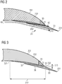
- Figure 2 shows a first example of a rotor blade.
- Figure 2 shows a cross sectional view of a part of the rotor blade. In particular, it illustrates the trailing edge section 23 of the rotor blade.
- the remaining rotor blade with the remaining trailing edge section 232 and a flap 30 which is attached to the remaining rotor blade at the remaining trailing edge section 232.
- a suction side 281 and a pressure side 282 can be attributed to the rotor blade in Figure 2 .
- the flap 30 comprises a first portion which is attached to the remaining trailing edge section 232 and a second part which comprises the trailing edge 231 of the entire rotor blade. Both parts are divided or separated by a gap which is referred to as the air duct 31.
- This air duct 31 can also be referred to as an air channel.
- the air duct 31 has the technical effect that a part of the airflow 40 which is flowing from the leading edge section to the trailing edge section of the rotor blade at the pressure side 282 is deflected and diverted through the air duct 31.
- this portion of the airflow 40 which is deflected and guided through the air duct 31 is referenced by the reference numeral 42.
- this portion of the airflow 40 which is un-deflected by the air duct 31 is referred to as the un-deflected portion 41 of the airflow.
- the airflow i.e. the un-deflected portion 41 of the airflow 40, is also slightly deflected by the mere presence of the flap 30, but it is not specifically deflected by the air duct 31.
- the presence and the provision of the air duct 31 leads to a reduction of the lift coefficient of the airfoil and to the reduction of noise that is generated at the trailing edge section of the rotor blade.
- Figure 3 shows a similar view of a very similar flap 30 and focuses on the dimensions of the air duct 31. It can be seen that the chordwise extension of the air duct 31 needs to be measured from the upstream end 321 of the inlet portion 32 of the air duct 31 to the downstream end 322 of the outlet portion 33 of the air duct 31. This chordwise extension of the air duct 31 is referred to by the reference numeral 312.
- the height of the air duct 31 is substantially uniform and constant in the example of Figure 3 .
- the minimum height 313 is measured and determined by the length of the distance referred to by the reference numeral 313.
- FIGS 4 and 5 Another example is illustrated in Figures 4 and 5 .
- a flap 30 comprising an air duct 31 are shown.
- the inlet portion 32 and the outlet portion 33 can be seen in Figure 4 and Figure 5 , respectively.
- the attachment portion 34 and the pressure side portion 36 of the flap can be well discerned.
- the flap also comprises an alignment rim 35.
- This alignment rim is to be arranged at the trailing edge of the remaining trailing edge section of the rotor blade.
- the rim has the beneficial effect of facilitating alignment of the flap 30 during connection of the flap 30 with the remaining rotor blade. This alignment is even more facilitated by this alignment rim 35 if the flap has to be mounted and attached to an already existing rotor blade which is e.g. already mounted on a hub of a wind turbine.
- Figures 6 to 8 show an embodiment according to the invention of a flap 30 with an air duct 31.
- Figures 6 and 7 show perspective views focusing on the attachment portion 34 and the pressure side portion 36 of the flap 30.
- Figure 6 also shows the angle 37 between the attachment portion 34 and the pressure side portion 36. It can be seen, that the width of the air duct 31, i.e. the spanwise extension of the air duct 31, is increasing in the direction of the airflow. In other words, the side walls of the air duct 31 are diverting towards the trailing edge. By this measure, a particularly favorable flow guidance can be achieved.
- Figure 8 illustrates some dimensions of the air duct 31 and the flap 30: It can be seen that the spanwise extension exemplarily amounts to a few centimeters, while the minimum height 313 of the air duct is one centimeter and the ramp angle 37 amounts to one degree.
- the chordwise extension of the flap 30 as illustrated in the example of Figures 6 to 8 amounts to 20 centimeters.
Claims (12)
- Pale de rotor (20) d'une turbine éolienne, dans laquelle :- la pale de rotor (20) comprend un côté d'aspiration (281), un côté de pression (282), une section de bord de fuite (23) dotée d'un bord de fuite (231) et une section de bord d'attaque (24) dotée d'un bord d'attaque (241),- la pale de rotor (20) comprend un conduit d'air (31) au niveau de la section de bord de fuite (23) qui fournit une trajectoire d'écoulement du côté de pression (282) au côté d'aspiration (281),- le conduit d'air (31) comprend une partie d'entrée (32) et une partie de sortie (33),- le conduit d'air (31) est configuré de telle sorte qu'au moins une partie du flux d'air (40) de la section de bord d'attaque (24) à la section de bord de fuite (23) est guidée en permanence à travers le conduit d'air (31), caractérisé en ce que :- une extension dans le sens de l'envergure (311) de la partie d'entrée (32) du conduit d'air (31) augmente à partir d'une extrémité amont (321) de la partie d'entrée (32) vers le bord de fuite (231) de la pale de rotor (20).
- Pale de rotor (20) selon la revendication 1, dans laquelle la configuration du conduit d'air (31) est indépendante du mode de fonctionnement de la turbine éolienne.
- Pale de rotor (20) selon l'une des revendications précédentes, dans laquelle le conduit d'air (31) fait partie d'un volet (30) qui est composé d'une pièce séparée par rapport à la section de bord de fuite restante (232) de la pale de rotor (20).
- Pale de rotor (20) selon la revendication 3, dans laquelle le volet (30) comprend une partie de fixation (34) permettant de fixer le volet (30) à la section de bord de fuite restante (232) de la pale de rotor (20).
- Pale de rotor (20) selon la revendication 3 ou 4, dans laquelle :- le volet (30) comprend une partie latérale de pression (36) ,- la partie latérale de pression (36) remplace et étend au moins partiellement le côté de pression (282) de la section de bord de fuite restante (232) de la pale de rotor (20), et- l'angle (37) entre la partie de fixation (34) et la partie latérale de pression (36) se trouve entre un degré et vingt-cinq degrés, en particulier entre cinq degrés et quinze degrés.
- Pale de rotor (20) selon l'une des revendications 3 à 5, dans laquelle le volet (30) est fixé à la section de bord de fuite restante (232) de la pale de rotor (20) grâce à un lien adhésif.
- Pale de rotor (20) selon l'une des revendications précédentes, dans laquelle l'extension dans le sens de l'envergure (311) du conduit d'air (31) se situe entre 1 % et 200 % de la longueur de cordage, en particulier entre 2 % et 50 % de la longueur de cordage.
- Pale de rotor (20) selon l'une des revendications précédentes, dans laquelle l'extension dans le sens de la corde (312) du conduit d'air (31) entre l'extrémité amont (321) de la partie d'entrée (32) et l'extrémité aval (322) de la partie de sortie (33) se situe entre 2 % et 50 % de la longueur de cordage, en particulier entre 5 % et 20 % de la longueur de cordage.
- Pale de rotor (20) selon l'une des revendications précédentes, dans laquelle la hauteur minimum (313) du conduit d'air (31) dans une direction perpendiculaire à l'étendue (25) et perpendiculaire à la corde (26) se situe entre 0,1 % et 10 % de la longueur de cordage, en particulier entre 0,5 % et 5 % de la longueur de cordage.
- Pale de rotor (20) selon l'une des revendications précédentes, dans laquelle l'extrémité amont (331) de la partie de sortie (33) est disposée entre 75 % et 100 % de la longueur de cordage, en particulier entre 85 % et 100 %.
- Pale de rotor (20) selon l'une des revendications 1 à 10, dans laquelle l'extension dans le sens de l'envergure (311) de toute la partie de sortie (33) du conduit d'air (31) est sensiblement constante.
- Pale de rotor (20) selon l'une des revendications précédentes, dans laquelle le conduit d'air (31) est disposé à une position dans le sens de l'envergure de la pale de rotor (20) entre 20 % et 80 % de la longueur totale de la pale de rotor (20), en particulier entre 30 % et 70 % de la longueur totale de la pale de rotor (20).
Priority Applications (3)
| Application Number | Priority Date | Filing Date | Title |
|---|---|---|---|
| DK16160693.4T DK3219980T3 (en) | 2016-03-16 | 2016-03-16 | Rear-edge air duct of a wind turbine rotor wing |
| EP16160693.4A EP3219980B1 (fr) | 2016-03-16 | 2016-03-16 | Conduit d'air de bord de fuite d'une pale de rotor d'éolienne |
| US15/378,463 US20170268480A1 (en) | 2016-03-16 | 2016-12-14 | Trailing edge air duct of a wind turbine rotor blade |
Applications Claiming Priority (1)
| Application Number | Priority Date | Filing Date | Title |
|---|---|---|---|
| EP16160693.4A EP3219980B1 (fr) | 2016-03-16 | 2016-03-16 | Conduit d'air de bord de fuite d'une pale de rotor d'éolienne |
Publications (2)
| Publication Number | Publication Date |
|---|---|
| EP3219980A1 EP3219980A1 (fr) | 2017-09-20 |
| EP3219980B1 true EP3219980B1 (fr) | 2019-01-02 |
Family
ID=55542516
Family Applications (1)
| Application Number | Title | Priority Date | Filing Date |
|---|---|---|---|
| EP16160693.4A Not-in-force EP3219980B1 (fr) | 2016-03-16 | 2016-03-16 | Conduit d'air de bord de fuite d'une pale de rotor d'éolienne |
Country Status (3)
| Country | Link |
|---|---|
| US (1) | US20170268480A1 (fr) |
| EP (1) | EP3219980B1 (fr) |
| DK (1) | DK3219980T3 (fr) |
Families Citing this family (3)
| Publication number | Priority date | Publication date | Assignee | Title |
|---|---|---|---|---|
| DE102017112742A1 (de) * | 2017-06-09 | 2018-12-13 | Wobben Properties Gmbh | Rotorblatt für eine Windenergieanlage und Windenergieanlage |
| CN113048008B (zh) * | 2019-12-27 | 2023-06-13 | 江苏金风科技有限公司 | 叶片、载荷调节组件、风力发电机组及载荷调节方法 |
| US20230392575A1 (en) * | 2022-06-03 | 2023-12-07 | Hamilton Sundstrand Corporation | Trailing edge noise reduction using an airfoil with an internal bypass channel |
Family Cites Families (30)
| Publication number | Priority date | Publication date | Assignee | Title |
|---|---|---|---|---|
| US2456906A (en) * | 1938-12-19 | 1948-12-21 | Bechereau Louis | Supporting surfaces for aircraft |
| US2940690A (en) * | 1958-01-22 | 1960-06-14 | Ca Nat Research Council | Aircraft with split flaps and gas jet boundary layer control |
| US5088665A (en) * | 1989-10-31 | 1992-02-18 | The United States Of America As Represented By The Administrator Of The National Aeronautics And Space Administration | Serrated trailing edges for improving lift and drag characteristics of lifting surfaces |
| US6905092B2 (en) * | 2002-11-20 | 2005-06-14 | Airfoils, Incorporated | Laminar-flow airfoil |
| US8109473B2 (en) * | 2006-05-30 | 2012-02-07 | Israel Aerospace Industries Ltd. | Slotted high lift aerofoils |
| ATE537356T1 (de) * | 2006-06-09 | 2011-12-15 | Vestas Wind Sys As | Windturbinenrotorblatt und pitchgeregelte windturbine |
| DE102006049616B4 (de) * | 2006-10-20 | 2010-08-05 | Deutsches Zentrum für Luft- und Raumfahrt e.V. | Anordnung eines Aerodynamischen Bauteils mit einer geschlitzten Hinter- oder Seitenkante in einer Strömung |
| DK2053240T3 (da) * | 2007-10-22 | 2011-07-11 | Actiflow B V | Vindturbine med grænselagskontrol |
| GB2462308A (en) * | 2008-08-01 | 2010-02-03 | Vestas Wind Sys As | Extension portion for wind turbine blade |
| EP2253838A1 (fr) * | 2009-05-18 | 2010-11-24 | Lm Glasfiber A/S | Procédé de fonctionnement d'une éolienne |
| US8651813B2 (en) * | 2009-05-29 | 2014-02-18 | Donald James Long | Fluid dynamic body having escapelet openings for reducing induced and interference drag, and energizing stagnant flow |
| US8376704B2 (en) * | 2009-11-05 | 2013-02-19 | General Electric Company | Systems and method of assembling an air distribution system for use in a rotor blade of a wind turbine |
| US8303250B2 (en) * | 2009-12-30 | 2012-11-06 | General Electric Company | Method and apparatus for increasing lift on wind turbine blade |
| US20110206531A1 (en) * | 2010-02-22 | 2011-08-25 | Desktop Aeronautics | Efficient low-cost wind energy using passive circulation control |
| WO2011157849A2 (fr) * | 2010-06-18 | 2011-12-22 | Suzlon Blade Technology B.V. | Pale de rotor pour éolienne |
| US20110142595A1 (en) * | 2010-07-02 | 2011-06-16 | General Electric Company | Wind turbine blades with controlled active flow and vortex elements |
| US8011887B2 (en) * | 2010-07-21 | 2011-09-06 | General Electric Company | Rotor blade assembly |
| WO2012019655A1 (fr) * | 2010-08-10 | 2012-02-16 | Siemens Aktiengesellschaft | Elément d'ailette et procédé permettant d'améliorer l'efficacité d'une ailette de turbine éolienne |
| FR2965591B1 (fr) * | 2010-09-30 | 2012-08-31 | Alstom Hydro France | Poutre de supportage d'un carenage d'hydrolienne et hydrolienne comportant une telle poutre |
| US7976276B2 (en) * | 2010-11-04 | 2011-07-12 | General Electric Company | Noise reducer for rotor blade in wind turbine |
| US8834127B2 (en) * | 2011-09-09 | 2014-09-16 | General Electric Company | Extension for rotor blade in wind turbine |
| ITMI20121797A1 (it) * | 2012-10-23 | 2014-04-24 | Wilic Sarl | Appendice aerodinamica per una pala di un aerogeneratore e pala di aerogeneratore provvista di tale appendice aerodinamica |
| US9677537B2 (en) * | 2013-03-28 | 2017-06-13 | General Electric Company | Acoustic shield for noise reduction in wind turbines |
| US20150050154A1 (en) * | 2013-05-23 | 2015-02-19 | Kristian R. DIXON | Airfoil trailing edge apparatus for noise reduction |
| US10422317B2 (en) * | 2013-06-07 | 2019-09-24 | Peter Agtuca | Advertising horizontal axis wind generator |
| IL226859A (en) * | 2013-06-10 | 2017-09-28 | Abramov Danny | Slot wing with groove and wings for aircraft |
| US9494134B2 (en) * | 2013-11-20 | 2016-11-15 | General Electric Company | Noise reducing extension plate for rotor blade in wind turbine |
| US9476406B2 (en) * | 2014-04-14 | 2016-10-25 | Siemens Aktiengesellschaft | Vortex generators aligned with trailing edge features on wind turbine blade |
| WO2016008874A1 (fr) * | 2014-07-14 | 2016-01-21 | Lm Wp Patent Holding A/S | Pièce d'extension de coque aérodynamique pour une pale de turbine éolienne |
| WO2018103803A1 (fr) * | 2016-12-06 | 2018-06-14 | Vestas Wind Systems A/S | Pale d'éolienne ayant un bord de fuite tronqué |
-
2016
- 2016-03-16 DK DK16160693.4T patent/DK3219980T3/en active
- 2016-03-16 EP EP16160693.4A patent/EP3219980B1/fr not_active Not-in-force
- 2016-12-14 US US15/378,463 patent/US20170268480A1/en not_active Abandoned
Non-Patent Citations (1)
| Title |
|---|
| None * |
Also Published As
| Publication number | Publication date |
|---|---|
| EP3219980A1 (fr) | 2017-09-20 |
| DK3219980T3 (en) | 2019-04-08 |
| US20170268480A1 (en) | 2017-09-21 |
Similar Documents
| Publication | Publication Date | Title |
|---|---|---|
| CN109416017B (zh) | 具有锯齿状后缘的转子叶片 | |
| US9377005B2 (en) | Airfoil modifiers for wind turbine rotor blades | |
| US8087889B2 (en) | Wind turbine blade with deflectable flaps | |
| EP2799710B1 (fr) | Ensemble de pale de rotor comportant des générateurs de tourbillons pour éolienne | |
| CN105715449B (zh) | 具有涡流发生器的转子叶片和风力涡轮机 | |
| US8579594B2 (en) | Wind turbine blade with submerged boundary layer control means | |
| US10974818B2 (en) | Vortex generator arrangement for an airfoil | |
| EP3426914B1 (fr) | Pale de rotor à bord de fuite dentelé | |
| CN101354008B (zh) | 具有拱形襟翼的风轮机叶片 | |
| US9140233B2 (en) | Wind power generation system | |
| EP3144525A1 (fr) | Pale de rotor de turbine éolienne et enveloppe de bord d'attaque épaisse | |
| EP2851555A1 (fr) | Pale de rotor de turbine éolienne avec extension dentelée | |
| EP2107235A1 (fr) | Pale d'éolienne dotée d'une surface portante auxiliaire | |
| EP2309119A1 (fr) | Pale d'eolienne et generateur eolien l'utilisant | |
| US8408870B2 (en) | Wind turbine blade with cambering flaps controlled by surface pressure changes | |
| US20110142595A1 (en) | Wind turbine blades with controlled active flow and vortex elements | |
| EP2940293A1 (fr) | Dispositif aérodynamique d'une pale de rotor d'une éolienne | |
| EP2851553A1 (fr) | Agencement permettant de réduire le bruit d'une pale de rotor de turbine éolienne | |
| DK2527642T3 (en) | A wind power installation rotor blade and corresponding method | |
| EP2937558B1 (fr) | Dispositif de déviation d'écoulement d'une éolienne et méthode | |
| NL2011236C2 (en) | Rotor blade for a wind turbine, and wind turbine field. | |
| EP3219980B1 (fr) | Conduit d'air de bord de fuite d'une pale de rotor d'éolienne | |
| CN106468241B (zh) | 具有气流转换装置的风力涡轮机叶片及其方法 | |
| EP3181895A1 (fr) | Système à plaque de séparation pour une pale de turbine éolienne dentelée | |
| CN110730864B (zh) | 用于风能设施的转子叶片和风能设施 |
Legal Events
| Date | Code | Title | Description |
|---|---|---|---|
| PUAI | Public reference made under article 153(3) epc to a published international application that has entered the european phase |
Free format text: ORIGINAL CODE: 0009012 |
|
| STAA | Information on the status of an ep patent application or granted ep patent |
Free format text: STATUS: THE APPLICATION HAS BEEN PUBLISHED |
|
| AK | Designated contracting states |
Kind code of ref document: A1 Designated state(s): AL AT BE BG CH CY CZ DE DK EE ES FI FR GB GR HR HU IE IS IT LI LT LU LV MC MK MT NL NO PL PT RO RS SE SI SK SM TR |
|
| AX | Request for extension of the european patent |
Extension state: BA ME |
|
| STAA | Information on the status of an ep patent application or granted ep patent |
Free format text: STATUS: REQUEST FOR EXAMINATION WAS MADE |
|
| 17P | Request for examination filed |
Effective date: 20180205 |
|
| RBV | Designated contracting states (corrected) |
Designated state(s): AL AT BE BG CH CY CZ DE DK EE ES FI FR GB GR HR HU IE IS IT LI LT LU LV MC MK MT NL NO PL PT RO RS SE SI SK SM TR |
|
| GRAP | Despatch of communication of intention to grant a patent |
Free format text: ORIGINAL CODE: EPIDOSNIGR1 |
|
| STAA | Information on the status of an ep patent application or granted ep patent |
Free format text: STATUS: GRANT OF PATENT IS INTENDED |
|
| INTG | Intention to grant announced |
Effective date: 20180720 |
|
| RIC1 | Information provided on ipc code assigned before grant |
Ipc: F03D 7/02 20060101ALI20180709BHEP Ipc: F03D 1/06 20060101AFI20180709BHEP |
|
| GRAS | Grant fee paid |
Free format text: ORIGINAL CODE: EPIDOSNIGR3 |
|
| GRAA | (expected) grant |
Free format text: ORIGINAL CODE: 0009210 |
|
| STAA | Information on the status of an ep patent application or granted ep patent |
Free format text: STATUS: THE PATENT HAS BEEN GRANTED |
|
| AK | Designated contracting states |
Kind code of ref document: B1 Designated state(s): AL AT BE BG CH CY CZ DE DK EE ES FI FR GB GR HR HU IE IS IT LI LT LU LV MC MK MT NL NO PL PT RO RS SE SI SK SM TR |
|
| REG | Reference to a national code |
Ref country code: GB Ref legal event code: FG4D |
|
| REG | Reference to a national code |
Ref country code: CH Ref legal event code: EP Ref country code: AT Ref legal event code: REF Ref document number: 1084702 Country of ref document: AT Kind code of ref document: T Effective date: 20190115 |
|
| REG | Reference to a national code |
Ref country code: IE Ref legal event code: FG4D |
|
| REG | Reference to a national code |
Ref country code: DE Ref legal event code: R096 Ref document number: 602016008840 Country of ref document: DE |
|
| REG | Reference to a national code |
Ref country code: DK Ref legal event code: T3 Effective date: 20190404 |
|
| REG | Reference to a national code |
Ref country code: DE Ref legal event code: R081 Ref document number: 602016008840 Country of ref document: DE Owner name: SIEMENS GAMESA RENEWABLE ENERGY A/S, DK Free format text: FORMER OWNER: SIEMENS AKTIENGESELLSCHAFT, 80333 MUENCHEN, DE |
|
| REG | Reference to a national code |
Ref country code: NL Ref legal event code: MP Effective date: 20190102 |
|
| RAP2 | Party data changed (patent owner data changed or rights of a patent transferred) |
Owner name: SIEMENS GAMESA RENEWABLE ENERGY A/S |
|
| REG | Reference to a national code |
Ref country code: LT Ref legal event code: MG4D |
|
| REG | Reference to a national code |
Ref country code: AT Ref legal event code: MK05 Ref document number: 1084702 Country of ref document: AT Kind code of ref document: T Effective date: 20190102 |
|
| PG25 | Lapsed in a contracting state [announced via postgrant information from national office to epo] |
Ref country code: NL Free format text: LAPSE BECAUSE OF FAILURE TO SUBMIT A TRANSLATION OF THE DESCRIPTION OR TO PAY THE FEE WITHIN THE PRESCRIBED TIME-LIMIT Effective date: 20190102 |
|
| PG25 | Lapsed in a contracting state [announced via postgrant information from national office to epo] |
Ref country code: NO Free format text: LAPSE BECAUSE OF FAILURE TO SUBMIT A TRANSLATION OF THE DESCRIPTION OR TO PAY THE FEE WITHIN THE PRESCRIBED TIME-LIMIT Effective date: 20190402 Ref country code: FI Free format text: LAPSE BECAUSE OF FAILURE TO SUBMIT A TRANSLATION OF THE DESCRIPTION OR TO PAY THE FEE WITHIN THE PRESCRIBED TIME-LIMIT Effective date: 20190102 Ref country code: ES Free format text: LAPSE BECAUSE OF FAILURE TO SUBMIT A TRANSLATION OF THE DESCRIPTION OR TO PAY THE FEE WITHIN THE PRESCRIBED TIME-LIMIT Effective date: 20190102 Ref country code: SE Free format text: LAPSE BECAUSE OF FAILURE TO SUBMIT A TRANSLATION OF THE DESCRIPTION OR TO PAY THE FEE WITHIN THE PRESCRIBED TIME-LIMIT Effective date: 20190102 Ref country code: PT Free format text: LAPSE BECAUSE OF FAILURE TO SUBMIT A TRANSLATION OF THE DESCRIPTION OR TO PAY THE FEE WITHIN THE PRESCRIBED TIME-LIMIT Effective date: 20190502 Ref country code: LT Free format text: LAPSE BECAUSE OF FAILURE TO SUBMIT A TRANSLATION OF THE DESCRIPTION OR TO PAY THE FEE WITHIN THE PRESCRIBED TIME-LIMIT Effective date: 20190102 Ref country code: PL Free format text: LAPSE BECAUSE OF FAILURE TO SUBMIT A TRANSLATION OF THE DESCRIPTION OR TO PAY THE FEE WITHIN THE PRESCRIBED TIME-LIMIT Effective date: 20190102 |
|
| PG25 | Lapsed in a contracting state [announced via postgrant information from national office to epo] |
Ref country code: LV Free format text: LAPSE BECAUSE OF FAILURE TO SUBMIT A TRANSLATION OF THE DESCRIPTION OR TO PAY THE FEE WITHIN THE PRESCRIBED TIME-LIMIT Effective date: 20190102 Ref country code: HR Free format text: LAPSE BECAUSE OF FAILURE TO SUBMIT A TRANSLATION OF THE DESCRIPTION OR TO PAY THE FEE WITHIN THE PRESCRIBED TIME-LIMIT Effective date: 20190102 Ref country code: BG Free format text: LAPSE BECAUSE OF FAILURE TO SUBMIT A TRANSLATION OF THE DESCRIPTION OR TO PAY THE FEE WITHIN THE PRESCRIBED TIME-LIMIT Effective date: 20190402 Ref country code: GR Free format text: LAPSE BECAUSE OF FAILURE TO SUBMIT A TRANSLATION OF THE DESCRIPTION OR TO PAY THE FEE WITHIN THE PRESCRIBED TIME-LIMIT Effective date: 20190403 Ref country code: IS Free format text: LAPSE BECAUSE OF FAILURE TO SUBMIT A TRANSLATION OF THE DESCRIPTION OR TO PAY THE FEE WITHIN THE PRESCRIBED TIME-LIMIT Effective date: 20190502 Ref country code: RS Free format text: LAPSE BECAUSE OF FAILURE TO SUBMIT A TRANSLATION OF THE DESCRIPTION OR TO PAY THE FEE WITHIN THE PRESCRIBED TIME-LIMIT Effective date: 20190102 |
|
| REG | Reference to a national code |
Ref country code: GB Ref legal event code: 732E Free format text: REGISTERED BETWEEN 20190822 AND 20190828 |
|
| REG | Reference to a national code |
Ref country code: DE Ref legal event code: R097 Ref document number: 602016008840 Country of ref document: DE |
|
| PG25 | Lapsed in a contracting state [announced via postgrant information from national office to epo] |
Ref country code: AT Free format text: LAPSE BECAUSE OF FAILURE TO SUBMIT A TRANSLATION OF THE DESCRIPTION OR TO PAY THE FEE WITHIN THE PRESCRIBED TIME-LIMIT Effective date: 20190102 Ref country code: EE Free format text: LAPSE BECAUSE OF FAILURE TO SUBMIT A TRANSLATION OF THE DESCRIPTION OR TO PAY THE FEE WITHIN THE PRESCRIBED TIME-LIMIT Effective date: 20190102 Ref country code: CZ Free format text: LAPSE BECAUSE OF FAILURE TO SUBMIT A TRANSLATION OF THE DESCRIPTION OR TO PAY THE FEE WITHIN THE PRESCRIBED TIME-LIMIT Effective date: 20190102 Ref country code: RO Free format text: LAPSE BECAUSE OF FAILURE TO SUBMIT A TRANSLATION OF THE DESCRIPTION OR TO PAY THE FEE WITHIN THE PRESCRIBED TIME-LIMIT Effective date: 20190102 Ref country code: IT Free format text: LAPSE BECAUSE OF FAILURE TO SUBMIT A TRANSLATION OF THE DESCRIPTION OR TO PAY THE FEE WITHIN THE PRESCRIBED TIME-LIMIT Effective date: 20190102 Ref country code: MC Free format text: LAPSE BECAUSE OF FAILURE TO SUBMIT A TRANSLATION OF THE DESCRIPTION OR TO PAY THE FEE WITHIN THE PRESCRIBED TIME-LIMIT Effective date: 20190102 Ref country code: SK Free format text: LAPSE BECAUSE OF FAILURE TO SUBMIT A TRANSLATION OF THE DESCRIPTION OR TO PAY THE FEE WITHIN THE PRESCRIBED TIME-LIMIT Effective date: 20190102 Ref country code: AL Free format text: LAPSE BECAUSE OF FAILURE TO SUBMIT A TRANSLATION OF THE DESCRIPTION OR TO PAY THE FEE WITHIN THE PRESCRIBED TIME-LIMIT Effective date: 20190102 |
|
| REG | Reference to a national code |
Ref country code: CH Ref legal event code: PL |
|
| PLBE | No opposition filed within time limit |
Free format text: ORIGINAL CODE: 0009261 |
|
| STAA | Information on the status of an ep patent application or granted ep patent |
Free format text: STATUS: NO OPPOSITION FILED WITHIN TIME LIMIT |
|
| PG25 | Lapsed in a contracting state [announced via postgrant information from national office to epo] |
Ref country code: LU Free format text: LAPSE BECAUSE OF NON-PAYMENT OF DUE FEES Effective date: 20190316 Ref country code: SM Free format text: LAPSE BECAUSE OF FAILURE TO SUBMIT A TRANSLATION OF THE DESCRIPTION OR TO PAY THE FEE WITHIN THE PRESCRIBED TIME-LIMIT Effective date: 20190102 |
|
| 26N | No opposition filed |
Effective date: 20191003 |
|
| REG | Reference to a national code |
Ref country code: BE Ref legal event code: MM Effective date: 20190331 |
|
| PG25 | Lapsed in a contracting state [announced via postgrant information from national office to epo] |
Ref country code: IE Free format text: LAPSE BECAUSE OF NON-PAYMENT OF DUE FEES Effective date: 20190316 Ref country code: LI Free format text: LAPSE BECAUSE OF NON-PAYMENT OF DUE FEES Effective date: 20190331 Ref country code: CH Free format text: LAPSE BECAUSE OF NON-PAYMENT OF DUE FEES Effective date: 20190331 |
|
| PG25 | Lapsed in a contracting state [announced via postgrant information from national office to epo] |
Ref country code: SI Free format text: LAPSE BECAUSE OF FAILURE TO SUBMIT A TRANSLATION OF THE DESCRIPTION OR TO PAY THE FEE WITHIN THE PRESCRIBED TIME-LIMIT Effective date: 20190102 Ref country code: FR Free format text: LAPSE BECAUSE OF NON-PAYMENT OF DUE FEES Effective date: 20190331 Ref country code: BE Free format text: LAPSE BECAUSE OF NON-PAYMENT OF DUE FEES Effective date: 20190331 |
|
| PG25 | Lapsed in a contracting state [announced via postgrant information from national office to epo] |
Ref country code: TR Free format text: LAPSE BECAUSE OF FAILURE TO SUBMIT A TRANSLATION OF THE DESCRIPTION OR TO PAY THE FEE WITHIN THE PRESCRIBED TIME-LIMIT Effective date: 20190102 |
|
| PGFP | Annual fee paid to national office [announced via postgrant information from national office to epo] |
Ref country code: GB Payment date: 20200311 Year of fee payment: 5 Ref country code: DK Payment date: 20200324 Year of fee payment: 5 |
|
| PG25 | Lapsed in a contracting state [announced via postgrant information from national office to epo] |
Ref country code: MT Free format text: LAPSE BECAUSE OF NON-PAYMENT OF DUE FEES Effective date: 20190316 |
|
| PGFP | Annual fee paid to national office [announced via postgrant information from national office to epo] |
Ref country code: DE Payment date: 20200519 Year of fee payment: 5 |
|
| PG25 | Lapsed in a contracting state [announced via postgrant information from national office to epo] |
Ref country code: CY Free format text: LAPSE BECAUSE OF FAILURE TO SUBMIT A TRANSLATION OF THE DESCRIPTION OR TO PAY THE FEE WITHIN THE PRESCRIBED TIME-LIMIT Effective date: 20190102 |
|
| PG25 | Lapsed in a contracting state [announced via postgrant information from national office to epo] |
Ref country code: HU Free format text: LAPSE BECAUSE OF FAILURE TO SUBMIT A TRANSLATION OF THE DESCRIPTION OR TO PAY THE FEE WITHIN THE PRESCRIBED TIME-LIMIT; INVALID AB INITIO Effective date: 20160316 |
|
| REG | Reference to a national code |
Ref country code: DE Ref legal event code: R119 Ref document number: 602016008840 Country of ref document: DE |
|
| REG | Reference to a national code |
Ref country code: DK Ref legal event code: EBP Effective date: 20210331 |
|
| GBPC | Gb: european patent ceased through non-payment of renewal fee |
Effective date: 20210316 |
|
| PG25 | Lapsed in a contracting state [announced via postgrant information from national office to epo] |
Ref country code: GB Free format text: LAPSE BECAUSE OF NON-PAYMENT OF DUE FEES Effective date: 20210316 Ref country code: DE Free format text: LAPSE BECAUSE OF NON-PAYMENT OF DUE FEES Effective date: 20211001 |
|
| PG25 | Lapsed in a contracting state [announced via postgrant information from national office to epo] |
Ref country code: DK Free format text: LAPSE BECAUSE OF NON-PAYMENT OF DUE FEES Effective date: 20210331 |
|
| PG25 | Lapsed in a contracting state [announced via postgrant information from national office to epo] |
Ref country code: MK Free format text: LAPSE BECAUSE OF FAILURE TO SUBMIT A TRANSLATION OF THE DESCRIPTION OR TO PAY THE FEE WITHIN THE PRESCRIBED TIME-LIMIT Effective date: 20190102 |