EP3219964A1 - Engine bleed system with multi-tap bleed array - Google Patents
Engine bleed system with multi-tap bleed array Download PDFInfo
- Publication number
- EP3219964A1 EP3219964A1 EP17160296.4A EP17160296A EP3219964A1 EP 3219964 A1 EP3219964 A1 EP 3219964A1 EP 17160296 A EP17160296 A EP 17160296A EP 3219964 A1 EP3219964 A1 EP 3219964A1
- Authority
- EP
- European Patent Office
- Prior art keywords
- bleed
- engine
- aircraft
- taps
- air
- Prior art date
- Legal status (The legal status is an assumption and is not a legal conclusion. Google has not performed a legal analysis and makes no representation as to the accuracy of the status listed.)
- Granted
Links
- 239000000203 mixture Substances 0.000 claims abstract description 17
- 238000000034 method Methods 0.000 claims description 12
- 230000007613 environmental effect Effects 0.000 claims description 6
- 230000008878 coupling Effects 0.000 claims description 2
- 238000010168 coupling process Methods 0.000 claims description 2
- 238000005859 coupling reaction Methods 0.000 claims description 2
- 239000007789 gas Substances 0.000 description 57
- 230000006835 compression Effects 0.000 description 6
- 238000007906 compression Methods 0.000 description 6
- 239000000446 fuel Substances 0.000 description 6
- 238000011144 upstream manufacturing Methods 0.000 description 6
- 239000000567 combustion gas Substances 0.000 description 5
- 238000013461 design Methods 0.000 description 5
- 230000001276 controlling effect Effects 0.000 description 3
- 230000008901 benefit Effects 0.000 description 2
- 238000002485 combustion reaction Methods 0.000 description 2
- 230000008569 process Effects 0.000 description 2
- 230000004075 alteration Effects 0.000 description 1
- 230000000712 assembly Effects 0.000 description 1
- 238000000429 assembly Methods 0.000 description 1
- 238000006243 chemical reaction Methods 0.000 description 1
- 230000000694 effects Effects 0.000 description 1
- 239000000284 extract Substances 0.000 description 1
- 239000012530 fluid Substances 0.000 description 1
- 230000006870 function Effects 0.000 description 1
- 230000007246 mechanism Effects 0.000 description 1
- 238000012986 modification Methods 0.000 description 1
- 230000004048 modification Effects 0.000 description 1
- 238000012544 monitoring process Methods 0.000 description 1
- 230000003287 optical effect Effects 0.000 description 1
- 238000010248 power generation Methods 0.000 description 1
- 238000012545 processing Methods 0.000 description 1
- 230000001105 regulatory effect Effects 0.000 description 1
- 238000005096 rolling process Methods 0.000 description 1
- 238000006467 substitution reaction Methods 0.000 description 1
- 230000032258 transport Effects 0.000 description 1
Images


Classifications
-
- F—MECHANICAL ENGINEERING; LIGHTING; HEATING; WEAPONS; BLASTING
- F02—COMBUSTION ENGINES; HOT-GAS OR COMBUSTION-PRODUCT ENGINE PLANTS
- F02C—GAS-TURBINE PLANTS; AIR INTAKES FOR JET-PROPULSION PLANTS; CONTROLLING FUEL SUPPLY IN AIR-BREATHING JET-PROPULSION PLANTS
- F02C9/00—Controlling gas-turbine plants; Controlling fuel supply in air- breathing jet-propulsion plants
- F02C9/16—Control of working fluid flow
- F02C9/18—Control of working fluid flow by bleeding, bypassing or acting on variable working fluid interconnections between turbines or compressors or their stages
-
- B—PERFORMING OPERATIONS; TRANSPORTING
- B64—AIRCRAFT; AVIATION; COSMONAUTICS
- B64D—EQUIPMENT FOR FITTING IN OR TO AIRCRAFT; FLIGHT SUITS; PARACHUTES; ARRANGEMENTS OR MOUNTING OF POWER PLANTS OR PROPULSION TRANSMISSIONS IN AIRCRAFT
- B64D13/00—Arrangements or adaptations of air-treatment apparatus for aircraft crew or passengers, or freight space, or structural parts of the aircraft
- B64D13/06—Arrangements or adaptations of air-treatment apparatus for aircraft crew or passengers, or freight space, or structural parts of the aircraft the air being conditioned
-
- B—PERFORMING OPERATIONS; TRANSPORTING
- B64—AIRCRAFT; AVIATION; COSMONAUTICS
- B64D—EQUIPMENT FOR FITTING IN OR TO AIRCRAFT; FLIGHT SUITS; PARACHUTES; ARRANGEMENTS OR MOUNTING OF POWER PLANTS OR PROPULSION TRANSMISSIONS IN AIRCRAFT
- B64D15/00—De-icing or preventing icing on exterior surfaces of aircraft
- B64D15/02—De-icing or preventing icing on exterior surfaces of aircraft by ducted hot gas or liquid
- B64D15/04—Hot gas application
-
- B—PERFORMING OPERATIONS; TRANSPORTING
- B64—AIRCRAFT; AVIATION; COSMONAUTICS
- B64D—EQUIPMENT FOR FITTING IN OR TO AIRCRAFT; FLIGHT SUITS; PARACHUTES; ARRANGEMENTS OR MOUNTING OF POWER PLANTS OR PROPULSION TRANSMISSIONS IN AIRCRAFT
- B64D29/00—Power-plant nacelles, fairings, or cowlings
-
- F—MECHANICAL ENGINEERING; LIGHTING; HEATING; WEAPONS; BLASTING
- F02—COMBUSTION ENGINES; HOT-GAS OR COMBUSTION-PRODUCT ENGINE PLANTS
- F02C—GAS-TURBINE PLANTS; AIR INTAKES FOR JET-PROPULSION PLANTS; CONTROLLING FUEL SUPPLY IN AIR-BREATHING JET-PROPULSION PLANTS
- F02C3/00—Gas-turbine plants characterised by the use of combustion products as the working fluid
- F02C3/04—Gas-turbine plants characterised by the use of combustion products as the working fluid having a turbine driving a compressor
-
- F—MECHANICAL ENGINEERING; LIGHTING; HEATING; WEAPONS; BLASTING
- F02—COMBUSTION ENGINES; HOT-GAS OR COMBUSTION-PRODUCT ENGINE PLANTS
- F02C—GAS-TURBINE PLANTS; AIR INTAKES FOR JET-PROPULSION PLANTS; CONTROLLING FUEL SUPPLY IN AIR-BREATHING JET-PROPULSION PLANTS
- F02C6/00—Plural gas-turbine plants; Combinations of gas-turbine plants with other apparatus; Adaptations of gas- turbine plants for special use
- F02C6/04—Gas-turbine plants providing heated or pressurised working fluid for other apparatus, e.g. without mechanical power output
- F02C6/06—Gas-turbine plants providing heated or pressurised working fluid for other apparatus, e.g. without mechanical power output providing compressed gas
- F02C6/08—Gas-turbine plants providing heated or pressurised working fluid for other apparatus, e.g. without mechanical power output providing compressed gas the gas being bled from the gas-turbine compressor
-
- F—MECHANICAL ENGINEERING; LIGHTING; HEATING; WEAPONS; BLASTING
- F02—COMBUSTION ENGINES; HOT-GAS OR COMBUSTION-PRODUCT ENGINE PLANTS
- F02C—GAS-TURBINE PLANTS; AIR INTAKES FOR JET-PROPULSION PLANTS; CONTROLLING FUEL SUPPLY IN AIR-BREATHING JET-PROPULSION PLANTS
- F02C7/00—Features, components parts, details or accessories, not provided for in, or of interest apart form groups F02C1/00 - F02C6/00; Air intakes for jet-propulsion plants
- F02C7/04—Air intakes for gas-turbine plants or jet-propulsion plants
- F02C7/047—Heating to prevent icing
-
- F—MECHANICAL ENGINEERING; LIGHTING; HEATING; WEAPONS; BLASTING
- F02—COMBUSTION ENGINES; HOT-GAS OR COMBUSTION-PRODUCT ENGINE PLANTS
- F02C—GAS-TURBINE PLANTS; AIR INTAKES FOR JET-PROPULSION PLANTS; CONTROLLING FUEL SUPPLY IN AIR-BREATHING JET-PROPULSION PLANTS
- F02C7/00—Features, components parts, details or accessories, not provided for in, or of interest apart form groups F02C1/00 - F02C6/00; Air intakes for jet-propulsion plants
- F02C7/36—Power transmission arrangements between the different shafts of the gas turbine plant, or between the gas-turbine plant and the power user
-
- B—PERFORMING OPERATIONS; TRANSPORTING
- B64—AIRCRAFT; AVIATION; COSMONAUTICS
- B64D—EQUIPMENT FOR FITTING IN OR TO AIRCRAFT; FLIGHT SUITS; PARACHUTES; ARRANGEMENTS OR MOUNTING OF POWER PLANTS OR PROPULSION TRANSMISSIONS IN AIRCRAFT
- B64D13/00—Arrangements or adaptations of air-treatment apparatus for aircraft crew or passengers, or freight space, or structural parts of the aircraft
- B64D13/06—Arrangements or adaptations of air-treatment apparatus for aircraft crew or passengers, or freight space, or structural parts of the aircraft the air being conditioned
- B64D2013/0603—Environmental Control Systems
-
- Y—GENERAL TAGGING OF NEW TECHNOLOGICAL DEVELOPMENTS; GENERAL TAGGING OF CROSS-SECTIONAL TECHNOLOGIES SPANNING OVER SEVERAL SECTIONS OF THE IPC; TECHNICAL SUBJECTS COVERED BY FORMER USPC CROSS-REFERENCE ART COLLECTIONS [XRACs] AND DIGESTS
- Y02—TECHNOLOGIES OR APPLICATIONS FOR MITIGATION OR ADAPTATION AGAINST CLIMATE CHANGE
- Y02T—CLIMATE CHANGE MITIGATION TECHNOLOGIES RELATED TO TRANSPORTATION
- Y02T50/00—Aeronautics or air transport
- Y02T50/60—Efficient propulsion technologies, e.g. for aircraft
Definitions
- This disclosure relates to gas turbine engines, and more particularly to an engine bleed system with a multi-tap bleed array.
- Gas turbine engines are used in numerous applications, one of which is for providing thrust to an aircraft.
- Compressed air is typically tapped at a high pressure location near the combustor for auxiliary uses, such as environmental control of the aircraft.
- this high pressure air is typically hotter than can safely be supported by ductwork and delivery to the aircraft.
- a pre-cooler or heat exchanger is used to cool high-temperature engine bleed air and is typically located near the engine such that excessively hot air is not ducted through the wing of the aircraft for safety reasons. Diverting higher pressure and higher temperature air from the engine beyond the pressure needed reduces engine efficiency. Further, heat exchangers used to cool engine bleed air add to overall aircraft weight, which also reduces fuel burn efficiency.
- an engine bleed control system for a gas turbine engine of an aircraft.
- the engine bleed control system includes a multi-tap bleed array including a plurality of engine bleed taps coupled to a compressor source of a lower pressure compressor section before a highest pressure compressor section of the gas turbine engine.
- a highest stage of the engine bleed taps has a maximum bleed temperature below an auto-ignition point of a fuel-air mixture of the aircraft at idle engine power at a maximum aircraft altitude and a pressure suitable for pressurizing the aircraft at the maximum aircraft altitude.
- the engine bleed control system also includes a plurality of valves operable to extract bleed air from each of the engine bleed taps.
- the engine bleed control system further includes a controller operable to selectively open and close each of the valves based on a bleed air demand and control delivery of the bleed air to an aircraft use.
- further embodiments may include where the aircraft use is an environmental control system of the aircraft.
- further embodiments may include a pneumatic bleed for anti-icing at least a nacelle inlet of the gas turbine engine, where the pneumatic bleed is at a different engine stage than the engine bleed taps.
- further embodiments may include where a wing anti-icing system of the aircraft is powered by an engine generator.
- controller is operable to control delivery of a portion of the bleed air to an anti-icing system of the aircraft.
- further embodiments may include a lowest stage of the engine bleed taps has a maximum bleed temperature below the auto-ignition point of the fuel-air mixture of the aircraft at a highest engine power operation and a pressure suitable for pressurizing the aircraft.
- further embodiments may include where the maximum bleed temperature is 400 degrees Fahrenheit (204 degrees Celsius).
- further embodiments may include where the multi-tap bleed array and the valves are located below a pylon coupling a nacelle of the gas turbine engine to a wing of the aircraft.
- further embodiments may include where the gas turbine engine is a geared turbofan engine, and a low-turbine powered electric generator of the geared turbofan engine powers a wing anti-icing system of the aircraft.
- a gas turbine engine of an aircraft includes a fan section, a compressor section, a turbine section, and an engine bleed control system.
- the engine bleed control system includes a multi-tap bleed array including a plurality of engine bleed taps coupled to a compressor source of a lower pressure compressor section before a highest pressure compressor section of the gas turbine engine.
- the highest stage of the engine bleed taps has a maximum bleed temperature below an auto-ignition point of a fuel-air mixture of the aircraft at idle engine power at a maximum aircraft altitude and a pressure suitable for pressurizing the aircraft at the maximum aircraft altitude.
- the engine bleed control system also includes a plurality of valves operable to extract bleed air from each of the engine bleed taps.
- the engine bleed control system further includes a controller operable to selectively open and close each of the valves based on a bleed air demand and control delivery of the bleed air to an aircraft use.
- a method of controlling an engine bleed system for a gas turbine engine of an aircraft includes establishing multi-tap bleed array including a plurality of engine bleed taps coupled to a compressor source of a lower pressure compressor section before a highest pressure compressor section of the gas turbine engine.
- a highest stage of the engine bleed taps has a maximum bleed temperature below an auto-ignition point of a fuel-air mixture of the aircraft at idle engine power at a maximum aircraft altitude and a pressure suitable for pressurizing the aircraft at the maximum aircraft altitude.
- a plurality of valves operable to extract bleed air from each of the engine bleed taps is configured. Each of the valves is selectively opened and closed based on a bleed air demand to control delivery of the bleed air to an aircraft use.
- further embodiments may include where the aircraft use is an environmental control system of the aircraft and a lowest stage of the engine bleed taps has a maximum bleed temperature below the auto-ignition point of the fuel-air mixture of the aircraft at a highest engine power operation and a pressure suitable for pressurizing the aircraft, and may include providing anti-icing from a pneumatic bleed to at least a nacelle inlet of the gas turbine engine, where the pneumatic bleed is at a different engine stage than the engine bleed taps.
- further embodiments may include controlling delivery of a portion of the bleed air to an anti-icing system of the aircraft.
- gas turbine engines are rotary-type combustion turbine engines built around a power core made up of a compressor, combustor and turbine, arranged in flow series with an upstream inlet and downstream exhaust.
- the compressor compresses air from the inlet, which is mixed with fuel in the combustor and ignited to generate hot combustion gas.
- the turbine extracts energy from the expanding combustion gas, and drives the compressor via a common shaft. Energy is delivered in the form of rotational energy in the shaft, reactive thrust from the exhaust, or both. Compressed air can be extracted from various stages as bleed air.
- Gas turbine engines provide efficient, reliable power for a wide range of applications, including aviation and industrial power generation.
- Smaller-scale engines such as auxiliary power units typically utilize a one-spool design, with co-rotating compressor and turbine sections.
- Larger-scale jet engines and industrial gas turbines are generally arranged into a number of coaxially nested spools, which operate at different pressures and temperatures, and rotate at different speeds.
- each spool is subdivided into a number of stages, which are formed of alternating rows of rotor blade and stator vane airfoils.
- the airfoils are shaped to turn, accelerate and compress the working fluid flow, or to generate lift for conversion to rotational energy in the turbine.
- turbojet engines thrust is generated primarily from the exhaust.
- Modem fixed-wing aircraft generally employ turbofan and turboprop designs, in which the low pressure spool is coupled to a propulsion fan or propeller in turbofan with two turbines.
- turbofans with three turbines one turbine drives the fan, one turbine drives the first compressor section and the third turbine drives the second compressor section.
- Turboshaft engines are typically used on rotary-wing aircraft, including helicopters.
- Turbofan engines are commonly divided into high and low bypass configurations.
- High bypass turbofans generate thrust primarily from the fan, which drives airflow through a bypass duct oriented around the engine core. This design is common on commercial aircraft and military transports, where noise and fuel efficiency are primary concerns.
- Low bypass turbofans generate proportionally more thrust from the exhaust flow, providing greater specific thrust for use on high-performance aircraft, including supersonic jet fighters.
- Unducted (open rotor) turbofans and ducted propeller engines are also known, in a variety of counter-rotating and aft-mounted configurations.
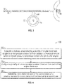
- FIG. 1 a cross-sectional view of a gas turbine engine 10, in a turbofan configuration is illustrated.
- the illustrated gas turbine engine 10 includes a fan section 11 with a propulsion fan 12 mounted inside a bypass duct 14 upstream of a fan exit guide vane 13.
- a power core of the engine is formed by a compressor section 16, a combustor 18 and a turbine section 20.
- Rotor blades (or airfoils) 21 in the compressor section 16 and/or the turbine section 20 are arranged in stages 38 with corresponding stator vanes (or airfoils) 39, where each stage 38 includes a rotor blade 21 and stator vane 39 pair.
- compressor section 16 includes a low pressure compressor 22 (a lower pressure compressor section) and a high pressure compressor 24(a highest pressure compressor section).
- the turbine section 20 includes high a pressure turbine 26 and a low pressure turbine 28.
- the low pressure compressor 22 is rotationally coupled to the low pressure turbine 28 via a low pressure shaft 30, thereby forming the low pressure spool or low spool 31.
- High pressure compressor 24 is rotationally coupled to the high pressure turbine 26 via a high pressure shaft 32, forming the high pressure spool or high spool 33.
- the fan 12 accelerates air flow from an inlet 34 through bypass duct 14, generating thrust.
- the core airflow is compressed in the low pressure compressor 22 and the high pressure compressor 24 and then the compressed airflow is mixed with fuel in the combustor 18 and ignited to generate combustion gas.
- the combustion gas expands to drive the high and low pressure turbines 26 and 28, which are rotationally coupled to high pressure compressor 24 and low pressure compressor 22, respectively. Expanded combustion gases exit through exhaust nozzle 36, which is shaped to generate additional thrust from the exhaust gas flow.
- the low pressure shaft 30 may be coupled to a low pressure compressor and then to a fan 12 via geared drive mechanism 37, providing improved fan speed control for increased efficiency and reduced engine noise as a geared turbofan engine.
- Propulsion fan 12 may also function as a first-stage compressor for gas turbine engine 10, with low pressure compressor 22 performing as an intermediate-stage compressor or booster in front of the high pressure compressor 24.
- the low pressure compressor stages are absent, and air from fan 12 is provided directly to high pressure compressor 24, or to an independently rotating intermediate compressor spool.
- An engine accessory gearbox 40 is mechanically coupled via a tower shaft 42 to a rotating portion of the gas turbine engine 10, such as the high pressure spool 33. Rotation of various engine accessories, such as pumps 44 and electric generators 46 (also referred to as engine generators 46), can be driven through the engine accessory gearbox 40 as depicted schematically in FIG. 1 .
- the engine accessory gearbox 40 can alternatively be coupled to low spool 31, and thus the electric generators 46 may also be referred to as low spool generators powered by rotation of the low pressure turbine 28 (i.e., lowest pressure turbine).
- the gas turbine engine 10 may have a range of different shaft and spool geometries, including one-spool, two-spool and three-spool configurations, in both co-rotating and counter-rotating designs.
- Gas turbine engine 10 may also be configured as a low bypass turbofan, an open-rotor turbofan, a ducted or un-ducted propeller engine, or an industrial gas turbine.
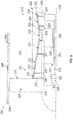
- FIG. 5 depicts another example of a gas turbine engine 220 in a geared turbofan configuration.
- the gas turbine engine 220 extends along an axial centerline 222 between an upstream airflow inlet 224 and a downstream airflow exhaust 226.
- the gas turbine engine 220 includes a fan section 228, a compressor section 216, a combustor section 232 and a turbine section 219.
- the compressor section 216 includes a low pressure compressor (LPC) section 229, an intermediate pressure compressor (IPC) section 230 and a high pressure compressor (HPC) section 231, where the LPC section 229 and IPC section 230 are lower pressure compressor section before the highest pressure compressor section of HPC section 231.
- the turbine section 219 includes a high pressure turbine (HPT) section 233, an intermediate pressure turbine (IPT) section 234 and a low pressure turbine (LPT) section 235.
- HPT high pressure turbine
- IPT intermediate pressure turbine
- LPT low pressure turbine
- the engine sections 228-235 are arranged sequentially along the centerline 222 within an engine housing 236.
- This housing 236 includes an inner (e.g., core) casing 238 and an outer (e.g., fan) casing 240.
- the inner casing 238 houses the LPC section 229 and the engine sections 230-235, which form a multi-spool core of the gas turbine engine 220.
- the outer casing 240 houses at least the fan section 228.
- the engine housing 236 also includes an inner (e.g., core) nacelle 242 and an outer (e.g., fan) nacelle 244.
- the inner nacelle 242 houses and provides an aerodynamic cover for the inner casing 238.
- the outer nacelle 244 houses and provides an aerodynamic cover the outer casing 240.
- the outer nacelle 244 also overlaps a portion of the inner nacelle 242 thereby defining a bypass gas path 246 radially between the nacelles 242 and 244.
- the bypass gas path 246, of course, may also be partially defined by the outer casing 240 and/or other components of the gas turbine engine 220.
- Each of the engine sections 228-231 and 233-235 includes a respective rotor 248-254.
- Each of these rotors 248-254 includes a plurality of rotor blades (e.g., fan blades, compressor blades or turbine blades) arranged circumferentially around and connected to one or more respective rotor disks.
- the rotor blades may be formed integral with or mechanically fastened, welded, brazed, adhered and/or otherwise attached to the respective rotor disk(s).
- the rotors 248-254 are respectively configured into a plurality of rotating assemblies 256-258.
- the first rotating assembly 256 includes the fan rotor 248, the LPC rotor 249 and the LPT rotor 254.
- the first rotating assembly 256 can also include a gear train 260 and one or more shafts 262 and 263, which gear train 260 may be configured as an epicyclic gear train with a planetary or star gear system.
- the LPC rotor 249 is connected to the fan rotor 248.
- the fan rotor 248 is connected to the gear train 260 through the fan shaft 262.
- the LPC rotor 249 is therefore connected to the gear train 260 through the fan rotor 248 and the fan shaft 262.
- the gear train 260 is connected to and driven by the LPT rotor 254 through the low speed shaft 263.
- the second rotating assembly 257 includes the IPC rotor 250 and the IPT rotor 253.
- the second rotating assembly 257 also includes an intermediate speed shaft 264.
- the IPC rotor 250 is connected to and driven by the IPT rotor 253 through the intermediate speed shaft 264.
- the third rotating assembly 258 includes the HPC rotor 251 and the HPT rotor 252.
- the third rotating assembly 258 also includes a high speed shaft 265.
- the HPC rotor 251 is connected to and driven by the HPT rotor 252 through the high speed shaft 265.
- One or more of the shafts 262-265 may be coaxial about the centerline 222. One or more of the shafts 263-265 may also be concentrically arranged.
- the low speed shaft 263 is disposed radially within and extends axially through the intermediate speed shaft 264.
- the intermediate speed shaft 264 is disposed radially within and extends axially through the high speed shaft 265.
- the shafts 262-265 are rotatably supported by a plurality of bearings; e.g., rolling element and/or thrust bearings. Each of these bearings is connected to the engine housing 236 (e.g., the inner casing 238) by at least one stationary structure such as, for example, an annular support strut.
- the core gas path 266 flows sequentially through the engine sections 229-235.
- the air within the core gas path 266 may be referred to as "core air”.
- the air within the bypass gas path 246 may be referred to as "bypass air”.
- the core air is compressed by the compressor rotors 249-251 and directed into the combustor section 232.
- Fuel is injected into the combustor section 232 and mixed with the compressed core air to provide a fuel-air mixture.
- This fuel air mixture is ignited and combustion products thereof flow through and sequentially cause the turbine rotors 252-254 to rotate.
- the rotation of the turbine rotors 252-254 respectively drive rotation of the compressor rotors 251-249 and, thus, compression of the air received from a core airflow inlet.
- the rotation of the turbine rotor 254 also drives rotation of the fan rotor 248, which propels bypass air through and out of the bypass gas path 246.
- the propulsion of the bypass air may account for a majority of thrust generated by the gas turbine engine 220, e.g., more than seventy-five percent (75%) of engine thrust.
- the gas turbine engine 220 of the present disclosure is not limited to the foregoing exemplary thrust ratio.
- FIG. 5 includes gear train 260, the gear train 260 can be eliminated in other embodiments that include two or more spools.
- FIG. 2 is a partial view of an engine bleed system 50 (also referred to as an engine bleed control system) according to an embodiment.
- the engine bleed system 50 includes a multi-tap bleed array 51 which includes a plurality of engine bleed taps 52A, 52B, 52C, 52D coupled to a compressor source 54 of the gas turbine engine 10.
- Each of the engine bleed taps 52A-52D can be located at a lower pressure location, for instance, before a ninth stage 55 of rotor blade 21 and stator vane 39 pairs of a compressor section 16 of the gas turbine engine 10.
- the compressor source 54 is the lowest pressure compressor source of compressor section 16.
- Engine bleed tap 52A is at an upstream location with respect to engine bleed taps 52B-52D and thus provides a source of lower compression and cooler bleed air as compared to bleed air extracted from engine bleed taps 52B-52D.
- engine bleed tap 52B is at an upstream location with respect to engine bleed taps 52C-52D and thus provides a source of lower compression and cooler bleed air as compared to bleed air extracted from engine bleed taps 52C-52D.
- Engine bleed tap 52D is at a downstream location with respect to engine bleed taps 52A-52C and thus provides a source of higher compression and hotter bleed air as compared to bleed air extracted from engine bleed taps 52A-52C.
- a highest stage of the engine bleed taps i.e., engine bleed tap 52D
- a lowest stage of the engine bleed taps (i.e., engine bleed tap 52A) has a maximum bleed temperature below the auto-ignition point of the fuel-air mixture of the aircraft at a highest engine power operation and a pressure suitable for pressurizing the aircraft.
- bleed air from engine bleed tap 52A is routed through a check valve 58A to intermediate duct 59.
- a valve 62A can control delivery of the bleed air from intermediate duct 59 to an aircraft use 64 through ducts 65.
- Valve 62A can be a shutoff valve or a combined pressure regulating and shutoff valve.
- the aircraft use 64 may be an environmental control system 90 of an aircraft 5, as best seen in FIG. 3 .
- Bleed air from engine bleed tap 52B can be routed through check valve 58B to intermediate duct 59 as controlled by valve 62B.
- Bleed air from engine bleed tap 52C can be routed through check valve 58C to intermediate duct 59 as controlled by valves 62B and 62C.
- Bleed air from engine bleed tap 52D can be routed to intermediate duct 59 as controlled by valves 62B, 62C, and 62D.
- Other configurations of the multi-tap bleed array 51 are contemplated, including different valve arrangements with a greater or lesser number of valves.
- valve 62C and/or valve 62D can be directly connected to intermediate duct 59.
- a pneumatic bleed 70 for anti-icing a nacelle inlet 72 ( FIG. 3 ) of the gas turbine engine 10 is provided for an engine anti-icing system 74.
- the engine anti-icing system 74 can provide anti-icing for engine components and/or nacelle components and can exceed 400 degrees Fahrenheit (204 degrees Celsius).
- the pneumatic bleed 70 can be at a different engine stage than the engine bleed taps 52A-52D, e.g., higher temperature/compression point downstream, but need not be located at the highest stage of compression.
- a valve 76 can be selectively actuated by a controller 48 to enable the engine anti-icing system 74.
- a wing anti-icing system 78 in wing 80 of the aircraft 5 is powered by an engine generator 46, i.e., electric anti-icing.
- the controller 48 is operable to control delivery of a portion of the bleed air to the wing anti-icing system 78 of the aircraft 5 using valve 82.
- the controller 48 may also control valves 62A-62D, as well as other components.
- the controller 48 may include memory to store instructions that are executed by a processor.
- the executable instructions may be stored or organized in any manner and at any level of abstraction, such as in connection with a controlling and/or monitoring operation of one or more systems of the gas turbine engine 10 of FIG. 1 .
- the processor can be any type of central processing unit (CPU), including a general purpose processor, a digital signal processor, a microcontroller, an application specific integrated circuit (ASIC), a field programmable gate array, or the like.
- the memory may include random access memory (RAM), read only memory (ROM), or other electronic, optical, magnetic, or any other computer readable medium onto which is stored data and control algorithms in a non-transitory form.
- the controller 48 can be embodied in an individual line-replaceable unit, within a control system (e.g., in an electronic engine control), and/or distributed between multiple electronic systems.
- source locations of the engine bleed taps 52A-52D are selected to hold a maximum temperature of the bleed air below an auto-ignition point of a fuel-air mixture at all flight conditions of the gas turbine engine 10.
- the maximum temperature can be established as 400 degrees Fahrenheit (204 degrees Celsius) for 0.25 mach and a 120 degree Fahrenheit day.
- the controller 48 may observe various aircraft operating conditions to determine pressures and temperatures at each of the engine bleed taps 52A-52D and selectively open and close valves 62A-62D based on a bleed air demand and control delivery of the bleed air to aircraft use 64 and/or wing anti-icing system 78.
- valve 82 may be located upstream of one or more of valves 62A-62D.
- output of one or more of the engine bleed taps 52A-52D may have other uses and/or connections with the wing anti-ice system 78 and/or other systems.
- the multi-tap bleed array 51 and/or valves 62A-62D may be located proximate to the gas turbine engine 10, below or within a pylon 84 ( FIG. 3 ) that couples a nacelle of the gas turbine engine 10 to wing 80, or within the aircraft 5.
- the engine bleed system 50 can be incorporated into the gas turbine engine 220 of FIG.
- engine bleed tap 52 can be coupled to a compressor source of a lower pressure compressor section (e.g., LPC section 229 or IPC section 230) before a highest pressure compressor section (HPC section 231) of the gas turbine engine 220 of FIG. 5 , for example.
- a compressor source of a lower pressure compressor section e.g., LPC section 229 or IPC section 230
- HPC section 231 a highest pressure compressor section of the gas turbine engine 220 of FIG. 5 , for example.
- FIG. 4 is a process flow of a method 100 according to an embodiment.
- the method 100 is described with reference to FIGS. 1-5 . Although described primarily in reference to the gas turbine engine 10 of FIG. 1 , it will be understood that the method 100 can also be applied to the gas turbine engine 220 of FIG. 5 and other configurations.
- multi-tap bleed array 51 is established with a plurality of engine bleed taps 52A-52D coupled to a compressor source 54 of a lower pressure compressor section before a highest pressure compressor section of the gas turbine engine 10, where a highest stage of the engine bleed taps (e.g., engine bleed tap 52D) has a maximum bleed temperature below an auto-ignition point of a fuel-air mixture of the aircraft at idle engine power at a maximum aircraft altitude and a pressure suitable for pressurizing the aircraft at the maximum aircraft altitude.
- valves 62A-62D are configured to extract bleed air from each of the engine bleed taps 52A-52D.
- Check valves 58A-58C can also control the flow of bleed air from engine bleed taps 52A-52D to intermediate duct 59, for instance.
- each of the valves 62A-62D is selectively opened and closed based on a bleed air demand to control delivery of the bleed air to an aircraft use 64.
- Anti-icing can be provided from a pneumatic bleed 70 to a nacelle inlet 74 of the gas turbine engine 10.
- Power from an engine generator 46 can be provided to a wing anti-icing system 78 of the aircraft 10.
- controller 48 controls delivery of a portion of the bleed air to the wing anti-icing system 78 of the aircraft 5, e.g., using a combination of valves 62A-62D and/or 82.
- Embodiments selectively open and close valves based on a bleed air demand to maintain pressure and temperature limits and avoid precooling the engine bleed air.
- Embodiments can eliminate the need for a pre-cooler or additional heat exchanger by selecting engine bleed air from an engine tap at targeted temperature and pressure while not exceeding the auto-ignition point of a fuel-air mixture.
Abstract
Description
- This disclosure relates to gas turbine engines, and more particularly to an engine bleed system with a multi-tap bleed array.
- Gas turbine engines are used in numerous applications, one of which is for providing thrust to an aircraft. Compressed air is typically tapped at a high pressure location near the combustor for auxiliary uses, such as environmental control of the aircraft. However, this high pressure air is typically hotter than can safely be supported by ductwork and delivery to the aircraft. Thus, a pre-cooler or heat exchanger is used to cool high-temperature engine bleed air and is typically located near the engine such that excessively hot air is not ducted through the wing of the aircraft for safety reasons. Diverting higher pressure and higher temperature air from the engine beyond the pressure needed reduces engine efficiency. Further, heat exchangers used to cool engine bleed air add to overall aircraft weight, which also reduces fuel burn efficiency.
- According to an embodiment, an engine bleed control system for a gas turbine engine of an aircraft is provided. The engine bleed control system includes a multi-tap bleed array including a plurality of engine bleed taps coupled to a compressor source of a lower pressure compressor section before a highest pressure compressor section of the gas turbine engine. A highest stage of the engine bleed taps has a maximum bleed temperature below an auto-ignition point of a fuel-air mixture of the aircraft at idle engine power at a maximum aircraft altitude and a pressure suitable for pressurizing the aircraft at the maximum aircraft altitude. The engine bleed control system also includes a plurality of valves operable to extract bleed air from each of the engine bleed taps. The engine bleed control system further includes a controller operable to selectively open and close each of the valves based on a bleed air demand and control delivery of the bleed air to an aircraft use.
- In addition to one or more of the features described above, or as an alternative to any of the foregoing embodiments, further embodiments may include where the aircraft use is an environmental control system of the aircraft.
- In addition to one or more of the features described above, or as an alternative to any of the foregoing embodiments, further embodiments may include a pneumatic bleed for anti-icing at least a nacelle inlet of the gas turbine engine, where the pneumatic bleed is at a different engine stage than the engine bleed taps.
- In addition to one or more of the features described above, or as an alternative to any of the foregoing embodiments, further embodiments may include where a wing anti-icing system of the aircraft is powered by an engine generator.
- In addition to one or more of the features described above, or as an alternative to any of the foregoing embodiments, further embodiments may include where the controller is operable to control delivery of a portion of the bleed air to an anti-icing system of the aircraft.
- In addition to one or more of the features described above, or as an alternative to any of the foregoing embodiments, further embodiments may include a lowest stage of the engine bleed taps has a maximum bleed temperature below the auto-ignition point of the fuel-air mixture of the aircraft at a highest engine power operation and a pressure suitable for pressurizing the aircraft.
- In addition to one or more of the features described above, or as an alternative to any of the foregoing embodiments, further embodiments may include where the maximum bleed temperature is 400 degrees Fahrenheit (204 degrees Celsius).
- In addition to one or more of the features described above, or as an alternative to any of the foregoing embodiments, further embodiments may include where the multi-tap bleed array and the valves are located below a pylon coupling a nacelle of the gas turbine engine to a wing of the aircraft.
- In addition to one or more of the features described above, or as an alternative to any of the foregoing embodiments, further embodiments may include where the gas turbine engine is a geared turbofan engine, and a low-turbine powered electric generator of the geared turbofan engine powers a wing anti-icing system of the aircraft.
- According to another embodiment, a gas turbine engine of an aircraft is provided. The gas turbine engine includes a fan section, a compressor section, a turbine section, and an engine bleed control system. The engine bleed control system includes a multi-tap bleed array including a plurality of engine bleed taps coupled to a compressor source of a lower pressure compressor section before a highest pressure compressor section of the gas turbine engine. The highest stage of the engine bleed taps has a maximum bleed temperature below an auto-ignition point of a fuel-air mixture of the aircraft at idle engine power at a maximum aircraft altitude and a pressure suitable for pressurizing the aircraft at the maximum aircraft altitude. The engine bleed control system also includes a plurality of valves operable to extract bleed air from each of the engine bleed taps. The engine bleed control system further includes a controller operable to selectively open and close each of the valves based on a bleed air demand and control delivery of the bleed air to an aircraft use.
- According to a further embodiment, a method of controlling an engine bleed system for a gas turbine engine of an aircraft is provided. The method includes establishing multi-tap bleed array including a plurality of engine bleed taps coupled to a compressor source of a lower pressure compressor section before a highest pressure compressor section of the gas turbine engine. A highest stage of the engine bleed taps has a maximum bleed temperature below an auto-ignition point of a fuel-air mixture of the aircraft at idle engine power at a maximum aircraft altitude and a pressure suitable for pressurizing the aircraft at the maximum aircraft altitude. A plurality of valves operable to extract bleed air from each of the engine bleed taps is configured. Each of the valves is selectively opened and closed based on a bleed air demand to control delivery of the bleed air to an aircraft use.
- In addition to one or more of the features described above, or as an alternative to any of the foregoing embodiments, further embodiments may include where the aircraft use is an environmental control system of the aircraft and a lowest stage of the engine bleed taps has a maximum bleed temperature below the auto-ignition point of the fuel-air mixture of the aircraft at a highest engine power operation and a pressure suitable for pressurizing the aircraft, and may include providing anti-icing from a pneumatic bleed to at least a nacelle inlet of the gas turbine engine, where the pneumatic bleed is at a different engine stage than the engine bleed taps.
- In addition to one or more of the features described above, or as an alternative to any of the foregoing embodiments, further embodiments may include controlling delivery of a portion of the bleed air to an anti-icing system of the aircraft.
- The subject matter which is regarded as the present disclosure is particularly pointed out and distinctly claimed in the claims at the conclusion of the specification. The foregoing and other features, and advantages of the present disclosure are apparent from the following detailed description taken in conjunction with the accompanying drawings in which:
-
FIG. 1 is a cross-sectional view of a gas turbine engine; -
FIG. 2 is a partial view of an engine bleed system according to an embodiment of the disclosure; -
FIG. 3 is a schematic view of an aircraft ice control system according to an embodiment of the disclosure; -
FIG. 4 is a process flow of a method according to embodiments of the disclosure; and -
FIG. 5 is a partial schematic view of another example of a gas turbine engine. - While the above-identified drawing figures set forth one or more embodiments of the invention, other embodiments are also contemplated. In all cases, this disclosure presents the invention by way of representation and not limitation. It should be understood that numerous other modifications and embodiments can be devised by those skilled in the art, which fall within the scope and spirit of the principles of the invention. The figures may not be drawn to scale, and applications and embodiments of the present disclosure may include features and components not specifically shown in the drawings. Like reference numerals identify similar structural elements.
- Various embodiments of the present disclosure are related to engine bleed control for a gas turbine engine. Embodiments of this disclosure may be applied on any turbomachinery from which compressed air is tapped off for auxiliary uses. For example, gas turbine engines are rotary-type combustion turbine engines built around a power core made up of a compressor, combustor and turbine, arranged in flow series with an upstream inlet and downstream exhaust. The compressor compresses air from the inlet, which is mixed with fuel in the combustor and ignited to generate hot combustion gas. The turbine extracts energy from the expanding combustion gas, and drives the compressor via a common shaft. Energy is delivered in the form of rotational energy in the shaft, reactive thrust from the exhaust, or both. Compressed air can be extracted from various stages as bleed air.
- Gas turbine engines provide efficient, reliable power for a wide range of applications, including aviation and industrial power generation. Smaller-scale engines such as auxiliary power units typically utilize a one-spool design, with co-rotating compressor and turbine sections. Larger-scale jet engines and industrial gas turbines are generally arranged into a number of coaxially nested spools, which operate at different pressures and temperatures, and rotate at different speeds.
- The individual compressor and turbine sections in each spool are subdivided into a number of stages, which are formed of alternating rows of rotor blade and stator vane airfoils. The airfoils are shaped to turn, accelerate and compress the working fluid flow, or to generate lift for conversion to rotational energy in the turbine.
- Aviation applications include turbojet, turbofan, turboprop and turboshaft engines. In turbojet engines, thrust is generated primarily from the exhaust. Modem fixed-wing aircraft generally employ turbofan and turboprop designs, in which the low pressure spool is coupled to a propulsion fan or propeller in turbofan with two turbines. Alternatively, in turbofans with three turbines, one turbine drives the fan, one turbine drives the first compressor section and the third turbine drives the second compressor section. Turboshaft engines are typically used on rotary-wing aircraft, including helicopters.
- Turbofan engines are commonly divided into high and low bypass configurations. High bypass turbofans generate thrust primarily from the fan, which drives airflow through a bypass duct oriented around the engine core. This design is common on commercial aircraft and military transports, where noise and fuel efficiency are primary concerns. Low bypass turbofans generate proportionally more thrust from the exhaust flow, providing greater specific thrust for use on high-performance aircraft, including supersonic jet fighters. Unducted (open rotor) turbofans and ducted propeller engines are also known, in a variety of counter-rotating and aft-mounted configurations.
- Referring now to
FIG. 1 , a cross-sectional view of agas turbine engine 10, in a turbofan configuration is illustrated. The illustratedgas turbine engine 10 includes afan section 11 with apropulsion fan 12 mounted inside abypass duct 14 upstream of a fanexit guide vane 13. A power core of the engine is formed by acompressor section 16, acombustor 18 and aturbine section 20. Rotor blades (or airfoils) 21 in thecompressor section 16 and/or theturbine section 20 are arranged instages 38 with corresponding stator vanes (or airfoils) 39, where eachstage 38 includes arotor blade 21 andstator vane 39 pair. - In the two-spool, high bypass configuration of
FIG. 1 ,compressor section 16 includes a low pressure compressor 22 (a lower pressure compressor section) and a high pressure compressor 24(a highest pressure compressor section). Theturbine section 20 includes high apressure turbine 26 and alow pressure turbine 28. - The
low pressure compressor 22 is rotationally coupled to thelow pressure turbine 28 via alow pressure shaft 30, thereby forming the low pressure spool orlow spool 31.High pressure compressor 24 is rotationally coupled to thehigh pressure turbine 26 via ahigh pressure shaft 32, forming the high pressure spool orhigh spool 33. - During operation of the
gas turbine engine 10, thefan 12 accelerates air flow from aninlet 34 throughbypass duct 14, generating thrust. The core airflow is compressed in thelow pressure compressor 22 and thehigh pressure compressor 24 and then the compressed airflow is mixed with fuel in thecombustor 18 and ignited to generate combustion gas. - The combustion gas expands to drive the high and
low pressure turbines high pressure compressor 24 andlow pressure compressor 22, respectively. Expanded combustion gases exit throughexhaust nozzle 36, which is shaped to generate additional thrust from the exhaust gas flow. - In advanced turbofan designs with a low pressure turbine and a high pressure turbine, the
low pressure shaft 30 may be coupled to a low pressure compressor and then to afan 12 via geareddrive mechanism 37, providing improved fan speed control for increased efficiency and reduced engine noise as a geared turbofan engine.Propulsion fan 12 may also function as a first-stage compressor forgas turbine engine 10, withlow pressure compressor 22 performing as an intermediate-stage compressor or booster in front of thehigh pressure compressor 24. Alternatively, the low pressure compressor stages are absent, and air fromfan 12 is provided directly tohigh pressure compressor 24, or to an independently rotating intermediate compressor spool. - An
engine accessory gearbox 40 is mechanically coupled via atower shaft 42 to a rotating portion of thegas turbine engine 10, such as thehigh pressure spool 33. Rotation of various engine accessories, such aspumps 44 and electric generators 46 (also referred to as engine generators 46), can be driven through theengine accessory gearbox 40 as depicted schematically inFIG. 1 . Theengine accessory gearbox 40 can alternatively be coupled tolow spool 31, and thus theelectric generators 46 may also be referred to as low spool generators powered by rotation of the low pressure turbine 28 (i.e., lowest pressure turbine). - The
gas turbine engine 10 may have a range of different shaft and spool geometries, including one-spool, two-spool and three-spool configurations, in both co-rotating and counter-rotating designs.Gas turbine engine 10 may also be configured as a low bypass turbofan, an open-rotor turbofan, a ducted or un-ducted propeller engine, or an industrial gas turbine. -
FIG. 5 depicts another example of agas turbine engine 220 in a geared turbofan configuration. Thegas turbine engine 220 extends along anaxial centerline 222 between anupstream airflow inlet 224 and adownstream airflow exhaust 226. Thegas turbine engine 220 includes afan section 228, acompressor section 216, acombustor section 232 and aturbine section 219. Thecompressor section 216 includes a low pressure compressor (LPC)section 229, an intermediate pressure compressor (IPC)section 230 and a high pressure compressor (HPC)section 231, where theLPC section 229 andIPC section 230 are lower pressure compressor section before the highest pressure compressor section ofHPC section 231. Theturbine section 219 includes a high pressure turbine (HPT)section 233, an intermediate pressure turbine (IPT)section 234 and a low pressure turbine (LPT)section 235. - The engine sections 228-235 are arranged sequentially along the
centerline 222 within an engine housing 236. This housing 236 includes an inner (e.g., core) casing 238 and an outer (e.g., fan)casing 240. Theinner casing 238 houses theLPC section 229 and the engine sections 230-235, which form a multi-spool core of thegas turbine engine 220. Theouter casing 240 houses at least thefan section 228. The engine housing 236 also includes an inner (e.g., core)nacelle 242 and an outer (e.g., fan)nacelle 244. Theinner nacelle 242 houses and provides an aerodynamic cover for theinner casing 238. Theouter nacelle 244 houses and provides an aerodynamic cover theouter casing 240. Theouter nacelle 244 also overlaps a portion of theinner nacelle 242 thereby defining abypass gas path 246 radially between thenacelles bypass gas path 246, of course, may also be partially defined by theouter casing 240 and/or other components of thegas turbine engine 220. - Each of the engine sections 228-231 and 233-235 includes a respective rotor 248-254. Each of these rotors 248-254 includes a plurality of rotor blades (e.g., fan blades, compressor blades or turbine blades) arranged circumferentially around and connected to one or more respective rotor disks. The rotor blades, for example, may be formed integral with or mechanically fastened, welded, brazed, adhered and/or otherwise attached to the respective rotor disk(s).
- The rotors 248-254 are respectively configured into a plurality of rotating assemblies 256-258. The first
rotating assembly 256 includes thefan rotor 248, theLPC rotor 249 and theLPT rotor 254. The firstrotating assembly 256 can also include agear train 260 and one ormore shafts gear train 260 may be configured as an epicyclic gear train with a planetary or star gear system. TheLPC rotor 249 is connected to thefan rotor 248. Thefan rotor 248 is connected to thegear train 260 through thefan shaft 262. TheLPC rotor 249 is therefore connected to thegear train 260 through thefan rotor 248 and thefan shaft 262. Thegear train 260 is connected to and driven by theLPT rotor 254 through thelow speed shaft 263. - The second
rotating assembly 257 includes theIPC rotor 250 and theIPT rotor 253. The secondrotating assembly 257 also includes anintermediate speed shaft 264. TheIPC rotor 250 is connected to and driven by theIPT rotor 253 through theintermediate speed shaft 264. - The third
rotating assembly 258 includes theHPC rotor 251 and theHPT rotor 252. The thirdrotating assembly 258 also includes ahigh speed shaft 265. TheHPC rotor 251 is connected to and driven by theHPT rotor 252 through thehigh speed shaft 265. - One or more of the shafts 262-265 may be coaxial about the
centerline 222. One or more of the shafts 263-265 may also be concentrically arranged. Thelow speed shaft 263 is disposed radially within and extends axially through theintermediate speed shaft 264. Theintermediate speed shaft 264 is disposed radially within and extends axially through thehigh speed shaft 265. The shafts 262-265 are rotatably supported by a plurality of bearings; e.g., rolling element and/or thrust bearings. Each of these bearings is connected to the engine housing 236 (e.g., the inner casing 238) by at least one stationary structure such as, for example, an annular support strut. - During operation, air enters the
gas turbine engine 220 through theairflow inlet 224. This air is directed through thefan section 228 and into acore gas path 266 and thebypass gas path 246. Thecore gas path 266 flows sequentially through the engine sections 229-235. The air within thecore gas path 266 may be referred to as "core air". The air within thebypass gas path 246 may be referred to as "bypass air". - The core air is compressed by the compressor rotors 249-251 and directed into the
combustor section 232. Fuel is injected into thecombustor section 232 and mixed with the compressed core air to provide a fuel-air mixture. This fuel air mixture is ignited and combustion products thereof flow through and sequentially cause the turbine rotors 252-254 to rotate. The rotation of the turbine rotors 252-254 respectively drive rotation of the compressor rotors 251-249 and, thus, compression of the air received from a core airflow inlet. The rotation of theturbine rotor 254 also drives rotation of thefan rotor 248, which propels bypass air through and out of thebypass gas path 246. The propulsion of the bypass air may account for a majority of thrust generated by thegas turbine engine 220, e.g., more than seventy-five percent (75%) of engine thrust. Thegas turbine engine 220 of the present disclosure, however, is not limited to the foregoing exemplary thrust ratio. Further, although the example ofFIG. 5 includesgear train 260, thegear train 260 can be eliminated in other embodiments that include two or more spools. -
FIG. 2 is a partial view of an engine bleed system 50 (also referred to as an engine bleed control system) according to an embodiment. In the example ofFIG. 2 , theengine bleed system 50 includes amulti-tap bleed array 51 which includes a plurality of engine bleed taps 52A, 52B, 52C, 52D coupled to acompressor source 54 of thegas turbine engine 10. Each of the engine bleed taps 52A-52D can be located at a lower pressure location, for instance, before aninth stage 55 ofrotor blade 21 andstator vane 39 pairs of acompressor section 16 of thegas turbine engine 10. In some embodiments, thecompressor source 54 is the lowest pressure compressor source ofcompressor section 16. Although the example ofFIG. 2 depicts four engine bleed taps 52A-52D, it will be understood that themulti-tap bleed array 51 can include any number of two or more engine bleed taps between a fan-air source 56 and a highest pressure compressor section ofcompressor section 16 in various embodiments.Engine bleed tap 52A is at an upstream location with respect to engine bleed taps 52B-52D and thus provides a source of lower compression and cooler bleed air as compared to bleed air extracted from engine bleed taps 52B-52D. Similarly,engine bleed tap 52B is at an upstream location with respect to engine bleed taps 52C-52D and thus provides a source of lower compression and cooler bleed air as compared to bleed air extracted from engine bleed taps 52C-52D.Engine bleed tap 52D is at a downstream location with respect to engine bleed taps 52A-52C and thus provides a source of higher compression and hotter bleed air as compared to bleed air extracted from engine bleed taps 52A-52C. In embodiments, a highest stage of the engine bleed taps (i.e.,engine bleed tap 52D) has a maximum bleed temperature below an auto-ignition point of a fuel-air mixture of the aircraft at idle engine power at a maximum aircraft altitude and a pressure suitable for pressurizing the aircraft at the maximum aircraft altitude. A lowest stage of the engine bleed taps (i.e.,engine bleed tap 52A) has a maximum bleed temperature below the auto-ignition point of the fuel-air mixture of the aircraft at a highest engine power operation and a pressure suitable for pressurizing the aircraft. - In the example of
FIG. 2 , bleed air fromengine bleed tap 52A is routed through acheck valve 58A tointermediate duct 59. Avalve 62A can control delivery of the bleed air fromintermediate duct 59 to anaircraft use 64 throughducts 65.Valve 62A can be a shutoff valve or a combined pressure regulating and shutoff valve. Theaircraft use 64 may be anenvironmental control system 90 of anaircraft 5, as best seen inFIG. 3 . Bleed air fromengine bleed tap 52B can be routed throughcheck valve 58B tointermediate duct 59 as controlled byvalve 62B. Bleed air fromengine bleed tap 52C can be routed throughcheck valve 58C tointermediate duct 59 as controlled byvalves engine bleed tap 52D can be routed tointermediate duct 59 as controlled byvalves multi-tap bleed array 51 are contemplated, including different valve arrangements with a greater or lesser number of valves. For example, rather than cascadingvalves 62B-62D,valve 62C and/orvalve 62D can be directly connected tointermediate duct 59. - In embodiments, a
pneumatic bleed 70 for anti-icing a nacelle inlet 72 (FIG. 3 ) of thegas turbine engine 10 is provided for anengine anti-icing system 74. Theengine anti-icing system 74 can provide anti-icing for engine components and/or nacelle components and can exceed 400 degrees Fahrenheit (204 degrees Celsius). Thepneumatic bleed 70 can be at a different engine stage than the engine bleed taps 52A-52D, e.g., higher temperature/compression point downstream, but need not be located at the highest stage of compression. Avalve 76 can be selectively actuated by acontroller 48 to enable theengine anti-icing system 74. In some embodiments, awing anti-icing system 78 inwing 80 of theaircraft 5 is powered by anengine generator 46, i.e., electric anti-icing. In alternate embodiments, thecontroller 48 is operable to control delivery of a portion of the bleed air to thewing anti-icing system 78 of theaircraft 5 usingvalve 82. Thecontroller 48 may also controlvalves 62A-62D, as well as other components. - The
controller 48 may include memory to store instructions that are executed by a processor. The executable instructions may be stored or organized in any manner and at any level of abstraction, such as in connection with a controlling and/or monitoring operation of one or more systems of thegas turbine engine 10 ofFIG. 1 . The processor can be any type of central processing unit (CPU), including a general purpose processor, a digital signal processor, a microcontroller, an application specific integrated circuit (ASIC), a field programmable gate array, or the like. Also, in embodiments, the memory may include random access memory (RAM), read only memory (ROM), or other electronic, optical, magnetic, or any other computer readable medium onto which is stored data and control algorithms in a non-transitory form. Thecontroller 48 can be embodied in an individual line-replaceable unit, within a control system (e.g., in an electronic engine control), and/or distributed between multiple electronic systems. - In the example of
FIG. 2 , source locations of the engine bleed taps 52A-52D are selected to hold a maximum temperature of the bleed air below an auto-ignition point of a fuel-air mixture at all flight conditions of thegas turbine engine 10. For instance, the maximum temperature can be established as 400 degrees Fahrenheit (204 degrees Celsius) for 0.25 mach and a 120 degree Fahrenheit day. Thecontroller 48 may observe various aircraft operating conditions to determine pressures and temperatures at each of the engine bleed taps 52A-52D and selectively open andclose valves 62A-62D based on a bleed air demand and control delivery of the bleed air toaircraft use 64 and/or winganti-icing system 78. - While a specific configuration is depicted in
FIG. 2 , other configurations are contemplated within the scope of embodiments. For instance, thevalve 82 may be located upstream of one or more ofvalves 62A-62D. Further, output of one or more of the engine bleed taps 52A-52D may have other uses and/or connections with thewing anti-ice system 78 and/or other systems. Themulti-tap bleed array 51 and/orvalves 62A-62D may be located proximate to thegas turbine engine 10, below or within a pylon 84 (FIG. 3 ) that couples a nacelle of thegas turbine engine 10 towing 80, or within theaircraft 5. Further, theengine bleed system 50 can be incorporated into thegas turbine engine 220 ofFIG. 5 , where engine bleed tap 52 can be coupled to a compressor source of a lower pressure compressor section (e.g.,LPC section 229 or IPC section 230) before a highest pressure compressor section (HPC section 231) of thegas turbine engine 220 ofFIG. 5 , for example. -
FIG. 4 is a process flow of amethod 100 according to an embodiment. Themethod 100 is described with reference toFIGS. 1-5 . Although described primarily in reference to thegas turbine engine 10 ofFIG. 1 , it will be understood that themethod 100 can also be applied to thegas turbine engine 220 ofFIG. 5 and other configurations. Atblock 102, multi-tap bleedarray 51 is established with a plurality of engine bleed taps 52A-52D coupled to acompressor source 54 of a lower pressure compressor section before a highest pressure compressor section of thegas turbine engine 10, where a highest stage of the engine bleed taps (e.g.,engine bleed tap 52D) has a maximum bleed temperature below an auto-ignition point of a fuel-air mixture of the aircraft at idle engine power at a maximum aircraft altitude and a pressure suitable for pressurizing the aircraft at the maximum aircraft altitude. Atblock 104,valves 62A-62D are configured to extract bleed air from each of the engine bleed taps 52A-52D. Checkvalves 58A-58C can also control the flow of bleed air from engine bleed taps 52A-52D tointermediate duct 59, for instance. Atblock 106, each of thevalves 62A-62D is selectively opened and closed based on a bleed air demand to control delivery of the bleed air to anaircraft use 64. Anti-icing can be provided from apneumatic bleed 70 to anacelle inlet 74 of thegas turbine engine 10. Power from anengine generator 46 can be provided to awing anti-icing system 78 of theaircraft 10. Alternatively,controller 48 controls delivery of a portion of the bleed air to thewing anti-icing system 78 of theaircraft 5, e.g., using a combination ofvalves 62A-62D and/or 82. - Technical effects and benefits include reducing engine bleed energy loss using multiple engine bleed taps and a peak temperature limit. Embodiments selectively open and close valves based on a bleed air demand to maintain pressure and temperature limits and avoid precooling the engine bleed air. Embodiments can eliminate the need for a pre-cooler or additional heat exchanger by selecting engine bleed air from an engine tap at targeted temperature and pressure while not exceeding the auto-ignition point of a fuel-air mixture.
- While the present disclosure has been described in detail in connection with only a limited number of embodiments, it should be readily understood that the present disclosure is not limited to such disclosed embodiments. Rather, the present disclosure can be modified to incorporate any number of variations, alterations or substitutions not heretofore described, but which are commensurate with the scope of the present disclosure. Additionally, while various embodiments of the present disclosure have been described, it is to be understood that aspects of the present disclosure may include only some of the described embodiments. Accordingly, the present disclosure is not to be seen as limited by the foregoing description, but is only limited by the scope of the appended claims.
Claims (12)
- An engine bleed control system (50) for a gas turbine engine of an aircraft, the engine bleed control system comprising:a multi-tap bleed array (51) comprising a plurality of engine bleed taps (52A-52D) coupled to a compressor source of a lower pressure compressor section before a highest pressure compressor section of the gas turbine engine (10), wherein a highest stage of the engine bleed taps has a maximum bleed temperature below an auto-ignition point of a fuel-air mixture of the aircraft at idle engine power at a maximum aircraft altitude and a pressure suitable for pressurizing the aircraft at the maximum aircraft altitude;a plurality of valves (58A-58C) operable to extract bleed air from each of the engine bleed taps; anda controller (48) operable to selectively open and close each of the valves based on a bleed air demand and control delivery of the bleed air to an aircraft use.
- The engine bleed control system as in claim 1, wherein the aircraft use is an environmental control system of the aircraft.
- The engine bleed control system as in claim 1, further comprising a pneumatic bleed for anti-icing at least a nacelle inlet of the gas turbine engine, wherein the pneumatic bleed is at a different engine stage than the engine bleed taps.
- The engine bleed control system as in claim 3, wherein a wing anti-icing system of the aircraft is powered by an engine generator.
- The engine bleed control system as in claim 3, wherein the controller is operable to control delivery of a portion of the bleed air to an anti-icing system of the aircraft.
- The engine bleed control system as in claim 1, wherein a lowest stage of the engine bleed taps has a maximum bleed temperature below the auto-ignition point of the fuel-air mixture of the aircraft at a highest engine power operation and a pressure suitable for pressurizing the aircraft.
- The engine bleed control system as in claim 6, wherein the maximum bleed temperature is 400 degrees Fahrenheit (204 degrees Celsius).
- The engine bleed control system as in claim 1, wherein the multi-tap bleed array and the valves are located below a pylon coupling a nacelle of the gas turbine engine to a wing of the aircraft.
- The engine bleed control system as in claim 1, wherein the gas turbine engine is a geared turbofan engine, and a low-turbine powered electric generator of the geared turbofan engine powers a wing anti-icing system of the aircraft.
- A method of controlling an engine bleed system for a gas turbine engine of an aircraft, the method comprising:establishing multi-tap bleed array comprising a plurality of engine bleed taps coupled to a compressor source of a lower pressure compressor section before a highest pressure compressor section of the gas turbine engine, wherein a highest stage of the engine bleed taps has a maximum bleed temperature below an auto-ignition point of a fuel-air mixture of the aircraft at idle engine power at a maximum aircraft altitude and a pressure suitable for pressurizing the aircraft at the maximum aircraft altitude;configuring a plurality of valves operable to extract bleed air from each of the engine bleed taps; andselectively opening and closing each of the valves based on a bleed air demand to control delivery of the bleed air to an aircraft use.
- The method as in claim 10, wherein the aircraft use is an environmental control system of the aircraft and a lowest stage of the engine bleed taps has a maximum bleed temperature below the auto-ignition point of the fuel-air mixture of the aircraft at a highest engine power operation and a pressure suitable for pressurizing the aircraft, and further comprising:providing anti-icing from a pneumatic bleed to at least a nacelle inlet of the gas turbine engine, wherein the pneumatic bleed is at a different engine stage than the engine bleed taps.
- The method as in claim 10, further comprising: controlling delivery of a portion of the bleed air to an anti-icing system of the aircraft.
Applications Claiming Priority (1)
| Application Number | Priority Date | Filing Date | Title |
|---|---|---|---|
| US15/070,462 US10794295B2 (en) | 2016-03-15 | 2016-03-15 | Engine bleed system with multi-tap bleed array |
Publications (2)
| Publication Number | Publication Date |
|---|---|
| EP3219964A1 true EP3219964A1 (en) | 2017-09-20 |
| EP3219964B1 EP3219964B1 (en) | 2023-03-01 |
Family
ID=58266953
Family Applications (1)
| Application Number | Title | Priority Date | Filing Date |
|---|---|---|---|
| EP17160296.4A Active EP3219964B1 (en) | 2016-03-15 | 2017-03-10 | Engine bleed system with multi-tap bleed array |
Country Status (5)
| Country | Link |
|---|---|
| US (1) | US10794295B2 (en) |
| EP (1) | EP3219964B1 (en) |
| CN (1) | CN107191276B (en) |
| BR (1) | BR102017004995B1 (en) |
| CA (1) | CA2960579C (en) |
Cited By (6)
| Publication number | Priority date | Publication date | Assignee | Title |
|---|---|---|---|---|
| EP3483412A1 (en) * | 2017-11-13 | 2019-05-15 | United Technologies Corporation | Gas turbine engine with mid-compressor bleed |
| EP3561268A1 (en) * | 2018-02-26 | 2019-10-30 | Rolls-Royce plc | Apparatus for a gas turbine engine |
| US11041441B2 (en) | 2018-02-26 | 2021-06-22 | Rolls-Royce Plc | Methods and apparatus for controlling at least a part of a start-up or re-light process of a gas turbine engine |
| US11149648B2 (en) | 2018-12-03 | 2021-10-19 | Rolls-Royce Plc | Methods and apparatus for controlling at least part of a start-up or re-light process of a gas turbine engine |
| US11149647B2 (en) | 2018-12-03 | 2021-10-19 | Rolls-Royce Plc | Methods and apparatus for controlling at least part of a start-up or re-light process of a gas turbine engine |
| US11365684B2 (en) | 2018-12-03 | 2022-06-21 | Rolls-Royce Plc | Methods and apparatus for controlling at least part of a start-up or re-light process of a gas turbine engine |
Families Citing this family (24)
| Publication number | Priority date | Publication date | Assignee | Title |
|---|---|---|---|---|
| US10093424B2 (en) * | 2014-07-07 | 2018-10-09 | United Technologies Corporation | Low pressure environmental control system with safe pylon transit |
| FR3007738B1 (en) * | 2013-06-28 | 2015-07-31 | Aircelle Sa | DEFROSTING AND PACKAGING DEVICE FOR AIRCRAFT |
| US9810158B2 (en) | 2014-04-01 | 2017-11-07 | The Boeing Company | Bleed air systems for use with aircraft and related methods |
| US10054051B2 (en) * | 2014-04-01 | 2018-08-21 | The Boeing Company | Bleed air systems for use with aircraft and related methods |
| US10100744B2 (en) | 2015-06-19 | 2018-10-16 | The Boeing Company | Aircraft bleed air and engine starter systems and related methods |
| US11473497B2 (en) | 2016-03-15 | 2022-10-18 | Hamilton Sundstrand Corporation | Engine bleed system with motorized compressor |
| US10822112B2 (en) * | 2018-02-14 | 2020-11-03 | General Electric Company | Slope-based event detection for turbine engines |
| US11078841B2 (en) * | 2018-04-09 | 2021-08-03 | The Boeing Company | Bleed air systems for use with aircraft and related methods |
| GB201807840D0 (en) * | 2018-05-15 | 2018-06-27 | Rolls Royce Plc | Gas turbine engine |
| CN108526671A (en) * | 2018-05-30 | 2018-09-14 | 成都华川电装有限责任公司 | The pawl pole rotor of generator and the welding tooling of fan |
| US10954865B2 (en) | 2018-06-19 | 2021-03-23 | The Boeing Company | Pressurized air systems for aircraft and related methods |
| US11186382B2 (en) * | 2018-11-02 | 2021-11-30 | General Electric Company | Fuel oxygen conversion unit |
| US11161622B2 (en) * | 2018-11-02 | 2021-11-02 | General Electric Company | Fuel oxygen reduction unit |
| US11465757B2 (en) | 2018-12-06 | 2022-10-11 | The Boeing Company | Systems and methods to produce aircraft cabin supply air |
| US11434010B2 (en) | 2019-02-08 | 2022-09-06 | Hamilton Sundstrand Corporation | Environmental control systems and methods of controlling airflow through environmental control systems |
| US11274599B2 (en) | 2019-03-27 | 2022-03-15 | Pratt & Whitney Canada Corp. | Air system switching system to allow aero-engines to operate in standby mode |
| US11391219B2 (en) | 2019-04-18 | 2022-07-19 | Pratt & Whitney Canada Corp. | Health monitor for air switching system |
| US11859563B2 (en) | 2019-05-31 | 2024-01-02 | Pratt & Whitney Canada Corp. | Air system of multi-engine aircraft |
| US11274611B2 (en) | 2019-05-31 | 2022-03-15 | Pratt & Whitney Canada Corp. | Control logic for gas turbine engine fuel economy |
| GB2584695A (en) * | 2019-06-12 | 2020-12-16 | Rolls Royce Plc | Reducing low flight Mach number fuel consumption |
| US11326525B2 (en) | 2019-10-11 | 2022-05-10 | Pratt & Whitney Canada Corp. | Aircraft bleed air systems and methods |
| CN111852657B (en) * | 2020-06-15 | 2021-08-06 | 中国航发湖南动力机械研究所 | Double-flow-path air-entraining mixing anti-icing device and method and aircraft engine |
| CN112212014B (en) * | 2020-09-18 | 2022-08-19 | 中国航发沈阳发动机研究所 | Valve design method for adaptively adjusting ventilation mode of aero-engine |
| US11788465B2 (en) * | 2022-01-19 | 2023-10-17 | General Electric Company | Bleed flow assembly for a gas turbine engine |
Citations (3)
| Publication number | Priority date | Publication date | Assignee | Title |
|---|---|---|---|---|
| EP1923575A2 (en) * | 2006-11-16 | 2008-05-21 | Honeywell International Inc. | Servo-controlled variable geometry ejector pump |
| US20100107594A1 (en) * | 2008-10-31 | 2010-05-06 | General Electric Company | Turbine integrated bleed system and method for a gas turbine engine |
| EP2492199A2 (en) * | 2011-02-28 | 2012-08-29 | General Electric Company | Environmental control system supply precooler bypass |
Family Cites Families (39)
| Publication number | Priority date | Publication date | Assignee | Title |
|---|---|---|---|---|
| US4041695A (en) * | 1975-11-21 | 1977-08-16 | The Garrett Corporation | Fuel system pneumatic purge apparatus and method |
| US5114100A (en) | 1989-12-29 | 1992-05-19 | The Boeing Company | Anti-icing system for aircraft |
| US5063963A (en) * | 1990-08-09 | 1991-11-12 | General Electric Company | Engine bleed air supply system |
| US5137230A (en) | 1991-06-04 | 1992-08-11 | General Electric Company | Aircraft gas turbine engine bleed air energy recovery apparatus |
| JP2001010596A (en) | 1999-06-30 | 2001-01-16 | Shimadzu Corp | Air conditioner for aircraft |
| US6305156B1 (en) | 1999-09-03 | 2001-10-23 | Alliedsignal Inc. | Integrated bleed air and engine starting system |
| US6189324B1 (en) | 1999-10-05 | 2001-02-20 | Samuel B. Williams | Environment control unit for turbine engine |
| WO2002066324A2 (en) | 2001-02-16 | 2002-08-29 | Hamilton Sundstrand Corporation | Improved aircraft system architecture |
| US20070220900A1 (en) | 2006-03-27 | 2007-09-27 | General Electric Company | Auxiliary gas turbine engine assembly, aircraft component and controller |
| FR2911848B1 (en) | 2007-01-31 | 2009-12-25 | Hispano Suiza Sa | CIRCUIT FOR SUPPLYING ELECTRIC ENERGY IN AN AIRCRAFT FOR ELECTRICAL EQUIPMENT COMPRISING A DEFROST CIRCUIT |
| DE102007057536B4 (en) | 2007-11-29 | 2011-03-17 | Airbus Operations Gmbh | Air conditioning with hybrid bleed air operation |
| US8529189B2 (en) | 2009-01-30 | 2013-09-10 | Honeywell International Inc. | Linear quadratic regulator control for bleed air system fan air valve |
| US8167551B2 (en) | 2009-03-26 | 2012-05-01 | United Technologies Corporation | Gas turbine engine with 2.5 bleed duct core case section |
| FR2948151B1 (en) * | 2009-07-17 | 2011-11-25 | Snecma | METHOD AND SYSTEM FOR CONTROLLING AN AIRCRAFT ENGINE STARTER-GENERATOR |
| US8176725B2 (en) | 2009-09-09 | 2012-05-15 | United Technologies Corporation | Reversed-flow core for a turbofan with a fan drive gear system |
| US8484983B2 (en) * | 2009-12-07 | 2013-07-16 | The Boeing Company | Thermoelectric generator on an aircraft bleed system |
| US8382039B2 (en) * | 2009-12-30 | 2013-02-26 | MRA Systems Inc. | Turbomachine nacelle and anti-icing system and method therefor |
| US9062604B2 (en) | 2011-01-14 | 2015-06-23 | Hamilton Sundstrand Corporation | Low pressure bleed architecture |
| US20130031912A1 (en) * | 2011-08-01 | 2013-02-07 | Hamilton Sundstrand Corporation | Gas turbine start architecture |
| US20130040545A1 (en) | 2011-08-11 | 2013-02-14 | Hamilton Sundstrand Corporation | Low pressure compressor bleed exit for an aircraft pressurization system |
| US8966875B2 (en) * | 2011-10-21 | 2015-03-03 | United Technologies Corporation | Constant speed transmission for gas turbine engine |
| GB2499578A (en) | 2011-11-29 | 2013-08-28 | Eaton Aerospace Ltd | Aircraft on board inert gas generation system |
| US9222411B2 (en) | 2011-12-21 | 2015-12-29 | General Electric Company | Bleed air and hot section component cooling air system and method |
| US8904805B2 (en) | 2012-01-09 | 2014-12-09 | United Technologies Corporation | Environmental control system for aircraft utilizing turbo-compressor |
| US8955794B2 (en) | 2012-01-24 | 2015-02-17 | The Boeing Company | Bleed air systems for use with aircrafts and related methods |
| US8967528B2 (en) | 2012-01-24 | 2015-03-03 | The Boeing Company | Bleed air systems for use with aircrafts and related methods |
| CN103047010B (en) * | 2012-11-28 | 2015-04-22 | 中国商用飞机有限责任公司 | Anti-icing system and anti-icing control method of inlet lip of engine |
| US10830133B2 (en) | 2013-09-03 | 2020-11-10 | Hamilton Sundstrand Corporation | Aircraft environmental control system selectively powered by three bleed ports |
| US20150065023A1 (en) | 2013-09-03 | 2015-03-05 | Hamilton Sundstrand Corporation | Intercompressor bleed turbo compressor |
| US9382841B2 (en) * | 2013-09-03 | 2016-07-05 | Hamilton Sundstrand Corporation | Aircraft environmental control system selectively powered by three bleed ports |
| US9657647B2 (en) | 2013-10-15 | 2017-05-23 | The Boeing Company | Methods and apparatus to adjust bleed ports on an aircraft engine |
| US9656756B2 (en) | 2014-03-10 | 2017-05-23 | The Boeing Company | Turbo-compressor system and method for extracting energy from an aircraft engine |
| US10054051B2 (en) | 2014-04-01 | 2018-08-21 | The Boeing Company | Bleed air systems for use with aircraft and related methods |
| US9810158B2 (en) | 2014-04-01 | 2017-11-07 | The Boeing Company | Bleed air systems for use with aircraft and related methods |
| GB201410180D0 (en) | 2014-06-09 | 2014-07-23 | Rolls Royce Plc | Method and apparatus for controlling a compressor of a gas turbine engine |
| EP2960467B1 (en) | 2014-06-27 | 2022-02-09 | Raytheon Technologies Corporation | Simplified engine bleed supply with low pressure environmental control system for aircraft |
| GB201513952D0 (en) | 2015-08-07 | 2015-09-23 | Rolls Royce Plc | Aircraft pneumatic system |
| US11473497B2 (en) | 2016-03-15 | 2022-10-18 | Hamilton Sundstrand Corporation | Engine bleed system with motorized compressor |
| US20170268430A1 (en) | 2016-03-15 | 2017-09-21 | Hamilton Sundstrand Corporation | Engine bleed system with turbo-compressor |
-
2016
- 2016-03-15 US US15/070,462 patent/US10794295B2/en active Active
-
2017
- 2017-03-10 EP EP17160296.4A patent/EP3219964B1/en active Active
- 2017-03-10 CA CA2960579A patent/CA2960579C/en active Active
- 2017-03-13 BR BR102017004995-7A patent/BR102017004995B1/en active IP Right Grant
- 2017-03-14 CN CN201710150483.7A patent/CN107191276B/en active Active
Patent Citations (3)
| Publication number | Priority date | Publication date | Assignee | Title |
|---|---|---|---|---|
| EP1923575A2 (en) * | 2006-11-16 | 2008-05-21 | Honeywell International Inc. | Servo-controlled variable geometry ejector pump |
| US20100107594A1 (en) * | 2008-10-31 | 2010-05-06 | General Electric Company | Turbine integrated bleed system and method for a gas turbine engine |
| EP2492199A2 (en) * | 2011-02-28 | 2012-08-29 | General Electric Company | Environmental control system supply precooler bypass |
Cited By (7)
| Publication number | Priority date | Publication date | Assignee | Title |
|---|---|---|---|---|
| EP3483412A1 (en) * | 2017-11-13 | 2019-05-15 | United Technologies Corporation | Gas turbine engine with mid-compressor bleed |
| US10626879B2 (en) | 2017-11-13 | 2020-04-21 | United Technologies Corporation | Gas turbine engine with mid-compressor bleed |
| EP3561268A1 (en) * | 2018-02-26 | 2019-10-30 | Rolls-Royce plc | Apparatus for a gas turbine engine |
| US11041441B2 (en) | 2018-02-26 | 2021-06-22 | Rolls-Royce Plc | Methods and apparatus for controlling at least a part of a start-up or re-light process of a gas turbine engine |
| US11149648B2 (en) | 2018-12-03 | 2021-10-19 | Rolls-Royce Plc | Methods and apparatus for controlling at least part of a start-up or re-light process of a gas turbine engine |
| US11149647B2 (en) | 2018-12-03 | 2021-10-19 | Rolls-Royce Plc | Methods and apparatus for controlling at least part of a start-up or re-light process of a gas turbine engine |
| US11365684B2 (en) | 2018-12-03 | 2022-06-21 | Rolls-Royce Plc | Methods and apparatus for controlling at least part of a start-up or re-light process of a gas turbine engine |
Also Published As
| Publication number | Publication date |
|---|---|
| US20170268431A1 (en) | 2017-09-21 |
| BR102017004995A2 (en) | 2017-09-19 |
| CN107191276B (en) | 2021-09-10 |
| CA2960579C (en) | 2023-10-24 |
| CN107191276A (en) | 2017-09-22 |
| US10794295B2 (en) | 2020-10-06 |
| BR102017004995B1 (en) | 2023-03-07 |
| CA2960579A1 (en) | 2017-09-15 |
| EP3219964B1 (en) | 2023-03-01 |
Similar Documents
| Publication | Publication Date | Title |
|---|---|---|
| EP3219964B1 (en) | Engine bleed system with multi-tap bleed array | |
| EP3219937B1 (en) | Engine bleed system with turbo-compressor and corresponding method | |
| EP3219620B1 (en) | Engine bleed system with motorized compressor | |
| US10457401B2 (en) | Dual-use air turbine system for a gas turbine engine | |
| US20220018262A1 (en) | Mechanically driven air vehicle thermal management device | |
| US10801371B2 (en) | Bowed rotor prevention system | |
| US8887485B2 (en) | Three spool gas turbine engine having a clutch and compressor bypass | |
| US11391211B2 (en) | Waste heat recovery system | |
| US10752375B2 (en) | Aircraft system | |
| EP2472081A2 (en) | Variable cycle gas turbine engine | |
| US11655767B2 (en) | Gearbox for an engine | |
| CN114909215A (en) | Propulsion system configuration and method of operation | |
| US20240110522A1 (en) | Shaft coupling for a gas turbine engine | |
| US11939913B2 (en) | Turbine engine with inverse Brayton cycle | |
| US20240117764A1 (en) | Air bottoming cycle driven propulsor |
Legal Events
| Date | Code | Title | Description |
|---|---|---|---|
| PUAI | Public reference made under article 153(3) epc to a published international application that has entered the european phase |
Free format text: ORIGINAL CODE: 0009012 |
|
| STAA | Information on the status of an ep patent application or granted ep patent |
Free format text: STATUS: THE APPLICATION HAS BEEN PUBLISHED |
|
| AK | Designated contracting states |
Kind code of ref document: A1 Designated state(s): AL AT BE BG CH CY CZ DE DK EE ES FI FR GB GR HR HU IE IS IT LI LT LU LV MC MK MT NL NO PL PT RO RS SE SI SK SM TR |
|
| AX | Request for extension of the european patent |
Extension state: BA ME |
|
| STAA | Information on the status of an ep patent application or granted ep patent |
Free format text: STATUS: REQUEST FOR EXAMINATION WAS MADE |
|
| 17P | Request for examination filed |
Effective date: 20180316 |
|
| RBV | Designated contracting states (corrected) |
Designated state(s): AL AT BE BG CH CY CZ DE DK EE ES FI FR GB GR HR HU IE IS IT LI LT LU LV MC MK MT NL NO PL PT RO RS SE SI SK SM TR |
|
| STAA | Information on the status of an ep patent application or granted ep patent |
Free format text: STATUS: EXAMINATION IS IN PROGRESS |
|
| 17Q | First examination report despatched |
Effective date: 20190320 |
|
| STAA | Information on the status of an ep patent application or granted ep patent |
Free format text: STATUS: EXAMINATION IS IN PROGRESS |
|
| STAA | Information on the status of an ep patent application or granted ep patent |
Free format text: STATUS: EXAMINATION IS IN PROGRESS |
|
| GRAP | Despatch of communication of intention to grant a patent |
Free format text: ORIGINAL CODE: EPIDOSNIGR1 |
|
| STAA | Information on the status of an ep patent application or granted ep patent |
Free format text: STATUS: GRANT OF PATENT IS INTENDED |
|
| INTG | Intention to grant announced |
Effective date: 20220927 |
|
| RAP3 | Party data changed (applicant data changed or rights of an application transferred) |
Owner name: HAMILTON SUNDSTRAND CORPORATION |
|
| GRAS | Grant fee paid |
Free format text: ORIGINAL CODE: EPIDOSNIGR3 |
|
| GRAA | (expected) grant |
Free format text: ORIGINAL CODE: 0009210 |
|
| STAA | Information on the status of an ep patent application or granted ep patent |
Free format text: STATUS: THE PATENT HAS BEEN GRANTED |
|
| AK | Designated contracting states |
Kind code of ref document: B1 Designated state(s): AL AT BE BG CH CY CZ DE DK EE ES FI FR GB GR HR HU IE IS IT LI LT LU LV MC MK MT NL NO PL PT RO RS SE SI SK SM TR |
|
| REG | Reference to a national code |
Ref country code: GB Ref legal event code: FG4D |
|
| REG | Reference to a national code |
Ref country code: CH Ref legal event code: EP Ref country code: AT Ref legal event code: REF Ref document number: 1551123 Country of ref document: AT Kind code of ref document: T Effective date: 20230315 |
|
| REG | Reference to a national code |
Ref country code: DE Ref legal event code: R096 Ref document number: 602017066347 Country of ref document: DE |
|
| REG | Reference to a national code |
Ref country code: IE Ref legal event code: FG4D |
|
| PGFP | Annual fee paid to national office [announced via postgrant information from national office to epo] |
Ref country code: DE Payment date: 20230221 Year of fee payment: 7 |
|
| REG | Reference to a national code |
Ref country code: LT Ref legal event code: MG9D |
|
| P01 | Opt-out of the competence of the unified patent court (upc) registered |
Effective date: 20230522 |
|
| REG | Reference to a national code |
Ref country code: NL Ref legal event code: MP Effective date: 20230301 |
|
| PG25 | Lapsed in a contracting state [announced via postgrant information from national office to epo] |
Ref country code: RS Free format text: LAPSE BECAUSE OF FAILURE TO SUBMIT A TRANSLATION OF THE DESCRIPTION OR TO PAY THE FEE WITHIN THE PRESCRIBED TIME-LIMIT Effective date: 20230301 Ref country code: NO Free format text: LAPSE BECAUSE OF FAILURE TO SUBMIT A TRANSLATION OF THE DESCRIPTION OR TO PAY THE FEE WITHIN THE PRESCRIBED TIME-LIMIT Effective date: 20230601 Ref country code: LV Free format text: LAPSE BECAUSE OF FAILURE TO SUBMIT A TRANSLATION OF THE DESCRIPTION OR TO PAY THE FEE WITHIN THE PRESCRIBED TIME-LIMIT Effective date: 20230301 Ref country code: LT Free format text: LAPSE BECAUSE OF FAILURE TO SUBMIT A TRANSLATION OF THE DESCRIPTION OR TO PAY THE FEE WITHIN THE PRESCRIBED TIME-LIMIT Effective date: 20230301 Ref country code: HR Free format text: LAPSE BECAUSE OF FAILURE TO SUBMIT A TRANSLATION OF THE DESCRIPTION OR TO PAY THE FEE WITHIN THE PRESCRIBED TIME-LIMIT Effective date: 20230301 Ref country code: ES Free format text: LAPSE BECAUSE OF FAILURE TO SUBMIT A TRANSLATION OF THE DESCRIPTION OR TO PAY THE FEE WITHIN THE PRESCRIBED TIME-LIMIT Effective date: 20230301 |
|
| PGFP | Annual fee paid to national office [announced via postgrant information from national office to epo] |
Ref country code: FR Payment date: 20230420 Year of fee payment: 7 |
|
| REG | Reference to a national code |
Ref country code: AT Ref legal event code: MK05 Ref document number: 1551123 Country of ref document: AT Kind code of ref document: T Effective date: 20230301 |
|
| PG25 | Lapsed in a contracting state [announced via postgrant information from national office to epo] |
Ref country code: SE Free format text: LAPSE BECAUSE OF FAILURE TO SUBMIT A TRANSLATION OF THE DESCRIPTION OR TO PAY THE FEE WITHIN THE PRESCRIBED TIME-LIMIT Effective date: 20230301 Ref country code: PL Free format text: LAPSE BECAUSE OF FAILURE TO SUBMIT A TRANSLATION OF THE DESCRIPTION OR TO PAY THE FEE WITHIN THE PRESCRIBED TIME-LIMIT Effective date: 20230301 Ref country code: NL Free format text: LAPSE BECAUSE OF FAILURE TO SUBMIT A TRANSLATION OF THE DESCRIPTION OR TO PAY THE FEE WITHIN THE PRESCRIBED TIME-LIMIT Effective date: 20230301 Ref country code: GR Free format text: LAPSE BECAUSE OF FAILURE TO SUBMIT A TRANSLATION OF THE DESCRIPTION OR TO PAY THE FEE WITHIN THE PRESCRIBED TIME-LIMIT Effective date: 20230602 Ref country code: FI Free format text: LAPSE BECAUSE OF FAILURE TO SUBMIT A TRANSLATION OF THE DESCRIPTION OR TO PAY THE FEE WITHIN THE PRESCRIBED TIME-LIMIT Effective date: 20230301 |
|
| PG25 | Lapsed in a contracting state [announced via postgrant information from national office to epo] |
Ref country code: SM Free format text: LAPSE BECAUSE OF FAILURE TO SUBMIT A TRANSLATION OF THE DESCRIPTION OR TO PAY THE FEE WITHIN THE PRESCRIBED TIME-LIMIT Effective date: 20230301 Ref country code: RO Free format text: LAPSE BECAUSE OF FAILURE TO SUBMIT A TRANSLATION OF THE DESCRIPTION OR TO PAY THE FEE WITHIN THE PRESCRIBED TIME-LIMIT Effective date: 20230301 Ref country code: PT Free format text: LAPSE BECAUSE OF FAILURE TO SUBMIT A TRANSLATION OF THE DESCRIPTION OR TO PAY THE FEE WITHIN THE PRESCRIBED TIME-LIMIT Effective date: 20230703 Ref country code: EE Free format text: LAPSE BECAUSE OF FAILURE TO SUBMIT A TRANSLATION OF THE DESCRIPTION OR TO PAY THE FEE WITHIN THE PRESCRIBED TIME-LIMIT Effective date: 20230301 Ref country code: CZ Free format text: LAPSE BECAUSE OF FAILURE TO SUBMIT A TRANSLATION OF THE DESCRIPTION OR TO PAY THE FEE WITHIN THE PRESCRIBED TIME-LIMIT Effective date: 20230301 Ref country code: AT Free format text: LAPSE BECAUSE OF FAILURE TO SUBMIT A TRANSLATION OF THE DESCRIPTION OR TO PAY THE FEE WITHIN THE PRESCRIBED TIME-LIMIT Effective date: 20230301 |
|
| PGFP | Annual fee paid to national office [announced via postgrant information from national office to epo] |
Ref country code: GB Payment date: 20230428 Year of fee payment: 7 |
|
| REG | Reference to a national code |
Ref country code: CH Ref legal event code: PL |
|
| PG25 | Lapsed in a contracting state [announced via postgrant information from national office to epo] |
Ref country code: SK Free format text: LAPSE BECAUSE OF FAILURE TO SUBMIT A TRANSLATION OF THE DESCRIPTION OR TO PAY THE FEE WITHIN THE PRESCRIBED TIME-LIMIT Effective date: 20230301 Ref country code: IS Free format text: LAPSE BECAUSE OF FAILURE TO SUBMIT A TRANSLATION OF THE DESCRIPTION OR TO PAY THE FEE WITHIN THE PRESCRIBED TIME-LIMIT Effective date: 20230701 |
|
| REG | Reference to a national code |
Ref country code: BE Ref legal event code: MM Effective date: 20230331 |
|
| REG | Reference to a national code |
Ref country code: DE Ref legal event code: R097 Ref document number: 602017066347 Country of ref document: DE |
|
| PG25 | Lapsed in a contracting state [announced via postgrant information from national office to epo] |
Ref country code: LU Free format text: LAPSE BECAUSE OF NON-PAYMENT OF DUE FEES Effective date: 20230310 |
|
| PLBE | No opposition filed within time limit |
Free format text: ORIGINAL CODE: 0009261 |
|
| STAA | Information on the status of an ep patent application or granted ep patent |
Free format text: STATUS: NO OPPOSITION FILED WITHIN TIME LIMIT |
|
| PG25 | Lapsed in a contracting state [announced via postgrant information from national office to epo] |
Ref country code: MC Free format text: LAPSE BECAUSE OF FAILURE TO SUBMIT A TRANSLATION OF THE DESCRIPTION OR TO PAY THE FEE WITHIN THE PRESCRIBED TIME-LIMIT Effective date: 20230301 |
|
| REG | Reference to a national code |
Ref country code: IE Ref legal event code: MM4A |
|
| PG25 | Lapsed in a contracting state [announced via postgrant information from national office to epo] |
Ref country code: SI Free format text: LAPSE BECAUSE OF FAILURE TO SUBMIT A TRANSLATION OF THE DESCRIPTION OR TO PAY THE FEE WITHIN THE PRESCRIBED TIME-LIMIT Effective date: 20230301 Ref country code: MC Free format text: LAPSE BECAUSE OF FAILURE TO SUBMIT A TRANSLATION OF THE DESCRIPTION OR TO PAY THE FEE WITHIN THE PRESCRIBED TIME-LIMIT Effective date: 20230301 Ref country code: LI Free format text: LAPSE BECAUSE OF NON-PAYMENT OF DUE FEES Effective date: 20230331 Ref country code: IE Free format text: LAPSE BECAUSE OF NON-PAYMENT OF DUE FEES Effective date: 20230310 Ref country code: DK Free format text: LAPSE BECAUSE OF FAILURE TO SUBMIT A TRANSLATION OF THE DESCRIPTION OR TO PAY THE FEE WITHIN THE PRESCRIBED TIME-LIMIT Effective date: 20230301 Ref country code: CH Free format text: LAPSE BECAUSE OF NON-PAYMENT OF DUE FEES Effective date: 20230331 |
|
| 26N | No opposition filed |
Effective date: 20231204 |
|
| PG25 | Lapsed in a contracting state [announced via postgrant information from national office to epo] |
Ref country code: BE Free format text: LAPSE BECAUSE OF NON-PAYMENT OF DUE FEES Effective date: 20230331 |