EP3219958A1 - Internally heated engine inlet screen for aircraft engines - Google Patents
Internally heated engine inlet screen for aircraft engines Download PDFInfo
- Publication number
- EP3219958A1 EP3219958A1 EP17160426.7A EP17160426A EP3219958A1 EP 3219958 A1 EP3219958 A1 EP 3219958A1 EP 17160426 A EP17160426 A EP 17160426A EP 3219958 A1 EP3219958 A1 EP 3219958A1
- Authority
- EP
- European Patent Office
- Prior art keywords
- tier
- engine
- mesh
- tubes
- compressor section
- Prior art date
- Legal status (The legal status is an assumption and is not a legal conclusion. Google has not performed a legal analysis and makes no representation as to the accuracy of the status listed.)
- Withdrawn
Links
- 239000012530 fluid Substances 0.000 claims abstract description 12
- 238000000034 method Methods 0.000 claims description 20
- 239000007787 solid Substances 0.000 claims description 5
- 230000003028 elevating effect Effects 0.000 claims description 3
- 230000001419 dependent effect Effects 0.000 claims 1
- 230000002265 prevention Effects 0.000 description 7
- 230000037361 pathway Effects 0.000 description 3
- 230000006835 compression Effects 0.000 description 2
- 238000007906 compression Methods 0.000 description 2
- 238000010276 construction Methods 0.000 description 2
- 238000010438 heat treatment Methods 0.000 description 2
- 238000009825 accumulation Methods 0.000 description 1
- 238000007796 conventional method Methods 0.000 description 1
- 238000004519 manufacturing process Methods 0.000 description 1
- 230000002085 persistent effect Effects 0.000 description 1
Images


Classifications
-
- F—MECHANICAL ENGINEERING; LIGHTING; HEATING; WEAPONS; BLASTING
- F02—COMBUSTION ENGINES; HOT-GAS OR COMBUSTION-PRODUCT ENGINE PLANTS
- F02C—GAS-TURBINE PLANTS; AIR INTAKES FOR JET-PROPULSION PLANTS; CONTROLLING FUEL SUPPLY IN AIR-BREATHING JET-PROPULSION PLANTS
- F02C7/00—Features, components parts, details or accessories, not provided for in, or of interest apart form groups F02C1/00 - F02C6/00; Air intakes for jet-propulsion plants
- F02C7/04—Air intakes for gas-turbine plants or jet-propulsion plants
- F02C7/047—Heating to prevent icing
-
- B—PERFORMING OPERATIONS; TRANSPORTING
- B64—AIRCRAFT; AVIATION; COSMONAUTICS
- B64D—EQUIPMENT FOR FITTING IN OR TO AIRCRAFT; FLIGHT SUITS; PARACHUTES; ARRANGEMENT OR MOUNTING OF POWER PLANTS OR PROPULSION TRANSMISSIONS IN AIRCRAFT
- B64D15/00—De-icing or preventing icing on exterior surfaces of aircraft
- B64D15/02—De-icing or preventing icing on exterior surfaces of aircraft by ducted hot gas or liquid
- B64D15/04—Hot gas application
-
- B—PERFORMING OPERATIONS; TRANSPORTING
- B64—AIRCRAFT; AVIATION; COSMONAUTICS
- B64D—EQUIPMENT FOR FITTING IN OR TO AIRCRAFT; FLIGHT SUITS; PARACHUTES; ARRANGEMENT OR MOUNTING OF POWER PLANTS OR PROPULSION TRANSMISSIONS IN AIRCRAFT
- B64D33/00—Arrangement in aircraft of power plant parts or auxiliaries not otherwise provided for
- B64D33/02—Arrangement in aircraft of power plant parts or auxiliaries not otherwise provided for of combustion air intakes
-
- F—MECHANICAL ENGINEERING; LIGHTING; HEATING; WEAPONS; BLASTING
- F02—COMBUSTION ENGINES; HOT-GAS OR COMBUSTION-PRODUCT ENGINE PLANTS
- F02C—GAS-TURBINE PLANTS; AIR INTAKES FOR JET-PROPULSION PLANTS; CONTROLLING FUEL SUPPLY IN AIR-BREATHING JET-PROPULSION PLANTS
- F02C6/00—Plural gas-turbine plants; Combinations of gas-turbine plants with other apparatus; Adaptations of gas-turbine plants for special use
- F02C6/04—Gas-turbine plants providing heated or pressurised working fluid for other apparatus, e.g. without mechanical power output
- F02C6/06—Gas-turbine plants providing heated or pressurised working fluid for other apparatus, e.g. without mechanical power output providing compressed gas
- F02C6/08—Gas-turbine plants providing heated or pressurised working fluid for other apparatus, e.g. without mechanical power output providing compressed gas the gas being bled from the gas-turbine compressor
-
- F—MECHANICAL ENGINEERING; LIGHTING; HEATING; WEAPONS; BLASTING
- F02—COMBUSTION ENGINES; HOT-GAS OR COMBUSTION-PRODUCT ENGINE PLANTS
- F02C—GAS-TURBINE PLANTS; AIR INTAKES FOR JET-PROPULSION PLANTS; CONTROLLING FUEL SUPPLY IN AIR-BREATHING JET-PROPULSION PLANTS
- F02C7/00—Features, components parts, details or accessories, not provided for in, or of interest apart form groups F02C1/00 - F02C6/00; Air intakes for jet-propulsion plants
- F02C7/04—Air intakes for gas-turbine plants or jet-propulsion plants
- F02C7/05—Air intakes for gas-turbine plants or jet-propulsion plants having provisions for obviating the penetration of damaging objects or particles
-
- F—MECHANICAL ENGINEERING; LIGHTING; HEATING; WEAPONS; BLASTING
- F02—COMBUSTION ENGINES; HOT-GAS OR COMBUSTION-PRODUCT ENGINE PLANTS
- F02C—GAS-TURBINE PLANTS; AIR INTAKES FOR JET-PROPULSION PLANTS; CONTROLLING FUEL SUPPLY IN AIR-BREATHING JET-PROPULSION PLANTS
- F02C7/00—Features, components parts, details or accessories, not provided for in, or of interest apart form groups F02C1/00 - F02C6/00; Air intakes for jet-propulsion plants
- F02C7/04—Air intakes for gas-turbine plants or jet-propulsion plants
- F02C7/05—Air intakes for gas-turbine plants or jet-propulsion plants having provisions for obviating the penetration of damaging objects or particles
- F02C7/055—Air intakes for gas-turbine plants or jet-propulsion plants having provisions for obviating the penetration of damaging objects or particles with intake grids, screens or guards
-
- F—MECHANICAL ENGINEERING; LIGHTING; HEATING; WEAPONS; BLASTING
- F04—POSITIVE - DISPLACEMENT MACHINES FOR LIQUIDS; PUMPS FOR LIQUIDS OR ELASTIC FLUIDS
- F04D—NON-POSITIVE-DISPLACEMENT PUMPS
- F04D29/00—Details, component parts, or accessories
- F04D29/40—Casings; Connections of working fluid
- F04D29/52—Casings; Connections of working fluid for axial pumps
- F04D29/522—Casings; Connections of working fluid for axial pumps especially adapted for elastic fluid pumps
-
- B—PERFORMING OPERATIONS; TRANSPORTING
- B64—AIRCRAFT; AVIATION; COSMONAUTICS
- B64D—EQUIPMENT FOR FITTING IN OR TO AIRCRAFT; FLIGHT SUITS; PARACHUTES; ARRANGEMENT OR MOUNTING OF POWER PLANTS OR PROPULSION TRANSMISSIONS IN AIRCRAFT
- B64D33/00—Arrangement in aircraft of power plant parts or auxiliaries not otherwise provided for
- B64D33/02—Arrangement in aircraft of power plant parts or auxiliaries not otherwise provided for of combustion air intakes
- B64D2033/022—Arrangement in aircraft of power plant parts or auxiliaries not otherwise provided for of combustion air intakes comprising bird or foreign object protections
-
- B—PERFORMING OPERATIONS; TRANSPORTING
- B64—AIRCRAFT; AVIATION; COSMONAUTICS
- B64D—EQUIPMENT FOR FITTING IN OR TO AIRCRAFT; FLIGHT SUITS; PARACHUTES; ARRANGEMENT OR MOUNTING OF POWER PLANTS OR PROPULSION TRANSMISSIONS IN AIRCRAFT
- B64D33/00—Arrangement in aircraft of power plant parts or auxiliaries not otherwise provided for
- B64D33/02—Arrangement in aircraft of power plant parts or auxiliaries not otherwise provided for of combustion air intakes
- B64D2033/0233—Arrangement in aircraft of power plant parts or auxiliaries not otherwise provided for of combustion air intakes comprising de-icing means
-
- B—PERFORMING OPERATIONS; TRANSPORTING
- B64—AIRCRAFT; AVIATION; COSMONAUTICS
- B64D—EQUIPMENT FOR FITTING IN OR TO AIRCRAFT; FLIGHT SUITS; PARACHUTES; ARRANGEMENT OR MOUNTING OF POWER PLANTS OR PROPULSION TRANSMISSIONS IN AIRCRAFT
- B64D33/00—Arrangement in aircraft of power plant parts or auxiliaries not otherwise provided for
- B64D33/02—Arrangement in aircraft of power plant parts or auxiliaries not otherwise provided for of combustion air intakes
- B64D2033/0246—Arrangement in aircraft of power plant parts or auxiliaries not otherwise provided for of combustion air intakes comprising particle separators
-
- B—PERFORMING OPERATIONS; TRANSPORTING
- B64—AIRCRAFT; AVIATION; COSMONAUTICS
- B64D—EQUIPMENT FOR FITTING IN OR TO AIRCRAFT; FLIGHT SUITS; PARACHUTES; ARRANGEMENT OR MOUNTING OF POWER PLANTS OR PROPULSION TRANSMISSIONS IN AIRCRAFT
- B64D33/00—Arrangement in aircraft of power plant parts or auxiliaries not otherwise provided for
- B64D33/02—Arrangement in aircraft of power plant parts or auxiliaries not otherwise provided for of combustion air intakes
- B64D2033/0266—Arrangement in aircraft of power plant parts or auxiliaries not otherwise provided for of combustion air intakes specially adapted for particular type of power plants
- B64D2033/0293—Arrangement in aircraft of power plant parts or auxiliaries not otherwise provided for of combustion air intakes specially adapted for particular type of power plants for turboprop engines
-
- F—MECHANICAL ENGINEERING; LIGHTING; HEATING; WEAPONS; BLASTING
- F05—INDEXING SCHEMES RELATING TO ENGINES OR PUMPS IN VARIOUS SUBCLASSES OF CLASSES F01-F04
- F05D—INDEXING SCHEME FOR ASPECTS RELATING TO NON-POSITIVE-DISPLACEMENT MACHINES OR ENGINES, GAS-TURBINES OR JET-PROPULSION PLANTS
- F05D2220/00—Application
- F05D2220/30—Application in turbines
- F05D2220/32—Application in turbines in gas turbines
-
- F—MECHANICAL ENGINEERING; LIGHTING; HEATING; WEAPONS; BLASTING
- F05—INDEXING SCHEMES RELATING TO ENGINES OR PUMPS IN VARIOUS SUBCLASSES OF CLASSES F01-F04
- F05D—INDEXING SCHEME FOR ASPECTS RELATING TO NON-POSITIVE-DISPLACEMENT MACHINES OR ENGINES, GAS-TURBINES OR JET-PROPULSION PLANTS
- F05D2240/00—Components
- F05D2240/10—Stators
- F05D2240/12—Fluid guiding means, e.g. vanes
- F05D2240/129—Cascades, i.e. assemblies of similar profiles acting in parallel
-
- F—MECHANICAL ENGINEERING; LIGHTING; HEATING; WEAPONS; BLASTING
- F05—INDEXING SCHEMES RELATING TO ENGINES OR PUMPS IN VARIOUS SUBCLASSES OF CLASSES F01-F04
- F05D—INDEXING SCHEME FOR ASPECTS RELATING TO NON-POSITIVE-DISPLACEMENT MACHINES OR ENGINES, GAS-TURBINES OR JET-PROPULSION PLANTS
- F05D2270/00—Control
- F05D2270/01—Purpose of the control system
- F05D2270/11—Purpose of the control system to prolong engine life
-
- Y—GENERAL TAGGING OF NEW TECHNOLOGICAL DEVELOPMENTS; GENERAL TAGGING OF CROSS-SECTIONAL TECHNOLOGIES SPANNING OVER SEVERAL SECTIONS OF THE IPC; TECHNICAL SUBJECTS COVERED BY FORMER USPC CROSS-REFERENCE ART COLLECTIONS [XRACs] AND DIGESTS
- Y02—TECHNOLOGIES OR APPLICATIONS FOR MITIGATION OR ADAPTATION AGAINST CLIMATE CHANGE
- Y02T—CLIMATE CHANGE MITIGATION TECHNOLOGIES RELATED TO TRANSPORTATION
- Y02T50/00—Aeronautics or air transport
- Y02T50/60—Efficient propulsion technologies, e.g. for aircraft
Definitions
- the present invention relates to aircraft engine deicing and icing prevention and more specifically to an apparatus for the prevention of ice build-up on inlet foreign object debris (FOD) screens through internal hot air heating.
- FOD foreign object debris
- Aircraft and aircraft engine icing is a persistent issue that must be dealt with in most aircraft applications.
- Prevention of ice build-up on inlet screens for the prevention of foreign object debris ("F OD") is necessary for protection from shedding damage, inlet airflow distortion, and inlet airflow blockage.
- Conventional methods of heating inlet FOD screens for anti-icing in deicing do not provide thermal energy from the engine compression system directly to the screen. Instead such conventional systems utilize an external source such as an off-engine hot air or engine/aircraft electrical power.
- an apparatus for providing foreign object debris protection and anti-icing capabilities to an air intake of an aircraft engine includes a frame having at least a portion configured to conduct fluids.
- a tube is positioned such that different portions of the frame are fluidly connected through the tube.
- An inlet is defined within the frame and is fluidly connected to a compressor section of the aircraft engine. In this manner, air from the compressor section of the aircraft engine can flow through the inlet, through the tube, and through the discharge outlet, to return to the compressor section of the aircraft engine.
- a method for providing anti-icing capabilities to the air intake of an aircraft engine wherein the aircraft intake is covered by mesh having at least a portion thereof configured to conduct fluids.
- the method includes the steps of: conducting heated air from a compressor section of the aircraft engine; conducting the heated air through the portion of mesh configured to conduct fluids; conducting heat through the mesh; elevating the temperature of the mesh; and returning the air to the compressor section of the aircraft engine.
- FIG. 1 shows an engine 12 that includes at least one screen 50 arranged in a screen assembly 38 such that the plurality of screens 50 each cover an air intake inlet 34.
- the screens 50 each include at least a portion that is heated with air that comes from the compressor section of the engine 12.
- the engine 12 also includes a propeller assembly 14, a pair of exhausts 22, and a mounting block 28.
- the engine 12 is a turboprop aircraft engine. In other embodiments the engine 12 could be configured for use in marine and industrial applications.
- the screen 50 includes a frame 53 configured to support unheated mesh 55 and a heated mesh assembly 70.
- the frame 53 is of tubular construction and includes a header 57, a first side duct 61, a second side duct 62, an intermediate duct 67, and a distal duct 58.
- the intermediate duct 67 stretches between, and fluidly connects, the first side duct 61 and the second side duct 62.
- the intermediate duct 67, portions of the first side duct 61 and the second side duct 62, and the distal duct 58 are configured to support the unheated mesh 55.
- the unheated mesh 55 is configured to allow air from the outside of the engine 12 through the air intake inlet 34 and into the air intake duct 32 while preventing foreign object debris (FOD) from entering the air intake duct 32.
- the header 57, portions of the side duct 61 and the second side duct 62, and the intermediate duct 67 are configured to support the heated mesh assembly 70.
- the frame 53 is generally comprised of hollow, tubular components. These components are configured to provide passageways for heated air.
- An inlet 63 is positioned in frame 53 along the header 57.
- the inlet 63 is configured to be fluidly connected to the bleed line 36 via a manifold 37 as illustrated in fig. 4 .
- the header 57 is configured to distribute heated air or gas from the compressor section 39 of the engine 12 around the frame 53 such that the frame 53 is heated.
- a plurality of discharge outlet 65 are formed in the fate frame 53 and release hot air from the frame 53 into the air intake duct 32.
- the header 57, the first side duct 61, the second side duct 62, and the distal duct 58 together are configured to fluidly connect the inlet 63 to the plurality of discharge outlets 65.
- the header 57 is also configured to distribute hot air to the heated mesh assembly 70.
- the heated mesh assembly 70 includes a first tier 73 of first tier tubes 74 that is positioned in contact with a second-tier 83 of second-tier tubes 74.
- Each first tier tube 74 has a first tier tube entry 75 and a first tier tube exit 77.
- Each first tier tube 74 defines at least a portion of a pathway that fluidly connects the header 57 to the intermediate duct 67.
- the entry end 75 is attached to the header 57 and the first tier tube exit end 77 is attached to the intermediate duct 67 for the majority of the first tier tubes 74.
- some of the first tier tubes 74 do not have an entry end 75 connected to the header 57 but instead have the entry end 75 connected to the first side duct 61.
- some of the first tier tubes 74 do not have an exit end 77 attached to the intermediate duct 67 but instead have the exit end 77 attached to the second side duct 62.
- each second-tier tube 84 has a second-tier tube entry 85 and a second tier tube exit 87.
- Each second tube 84 defines at least a portion of a pathway that fluidly connects the header 57 to one of the first side duct 61 and the second side duct 62.
- the entry end 85 is attached to the header 57 and the second tier tube exit end 87 is attached to the intermediate duct 67 for the majority of the second-tier tubes 84.
- some of the second-tier tubes 84 do not have an entry end 85 connected to the header 57 but instead have the entry end 85 connected to the side duct 62.
- some of the second-tier tubes 84 do not have an exit end 87 attached to the intermediate duct 67 but instead have the exit end 87 attached to the first side duct 61.
- the heated mesh assembly 70 and the frame 53 of the screen 50 are formed utilizing advanced manufacturing techniques in a unitary or monolithic piece preferably.
- the unheated mesh 55 of the screen 50 can be formed together with the other components of the screen 50 as a unitary or monolithic piece.
- the unheated mesh 55 can be positioned within and attached to the frame 53 which is can figured to receive it after the heated mesh assembly 70 and the frame 53 are formed together as can be seen in the 6, where second-tier tubes 84 cross first tier tubes 74 they share a common wall at intersection 92.
- a plurality of screen openings 94 are defined by the intersections 92 and portions of the first tier tubes 74 and the second-tier tubes 84. Openings 94 are sized such that FOD above a predetermined size and shape cannot pass through. In addition, the number of openings 94 in each screen 50 is also chosen to allow a predetermined airflow through screen 50. It is believed that the tubular construction of portions of the screen 50 provide additional strength with less weight than similarly sized solid components provide.
- FIG. 4 shows the screen assembly 38 in a radially exploded view including partial sections of the struts 31.
- the screen assembly 38 includes a plurality of the screens 50.
- the screens 50 are radially distributed around the engine 12 and each of the screens 50 are positioned over an air intake inlet 34 of an air intake duct 32.
- the air intake duct 32 is is defined by a strut 31.
- each screen 50 includes an inlet 63.
- Each of the inlets 63 are fluidly connected to a compressor section 39 of the engine 12 via a manifold 37 and a bleed line 36. It should be appreciated that in other embodiments, each of the inlets 63 can be connected directly to the compressor section 39 of the engine 12 via an individual bleed line. In these embodiments, there is no manifold positioned between the bleed line and the inlet 63.
- the present invention can be better understood by a description of the operation thereof.
- heat is generated.
- Hot air from the compressor section 39 is forced through the bleed line 36 and the manifold 37 to each of the screens 50.
- the hot air is conducted through the inlet 63 and along the header 57.
- the screen 50 is configured such that air flowing through pathways defined by the screen 50 such as the header 57 in the heated mesh assembly 70 is distributed in a predetermined manner among the different components.
- hot-air is distributed generally throughout the heated mesh assembly 70 and the frame 53. Heat from the air is conducted through the walls of the heated mesh assembly 70 and the frame 53.
- the present invention has advantages over the prior art.
- the present invention provides an efficient and cost-effective method for providing engine anti-icing and deicing functionality to an air intake inlet on aviation engines and other products.
- Unique features of this invention include active prevention of ice accumulation at the air intake inlet combined with FOD protection at the air intake inlet.
- the present invention provides for utilizing existing thermal energy to provide efficient and cost-effective anti-icing.
- New engine architectures require more robust is the price prevention at air intake inlets on aviation engines and apparatus of the present invention is robust compared to conventional deicing and FOD prevention and thus able to meet regulation requirements.
Landscapes
- Engineering & Computer Science (AREA)
- Chemical & Material Sciences (AREA)
- Combustion & Propulsion (AREA)
- Mechanical Engineering (AREA)
- General Engineering & Computer Science (AREA)
- Aviation & Aerospace Engineering (AREA)
- Structures Of Non-Positive Displacement Pumps (AREA)
- Heat-Exchange Devices With Radiators And Conduit Assemblies (AREA)
- Other Air-Conditioning Systems (AREA)
- Supercharger (AREA)
Abstract
Description
- The present invention relates to aircraft engine deicing and icing prevention and more specifically to an apparatus for the prevention of ice build-up on inlet foreign object debris (FOD) screens through internal hot air heating.
- Aircraft and aircraft engine icing is a persistent issue that must be dealt with in most aircraft applications. Prevention of ice build-up on inlet screens for the prevention of foreign object debris ("F OD") is necessary for protection from shedding damage, inlet airflow distortion, and inlet airflow blockage. Conventional methods of heating inlet FOD screens for anti-icing in deicing do not provide thermal energy from the engine compression system directly to the screen. Instead such conventional systems utilize an external source such as an off-engine hot air or engine/aircraft electrical power.
- This need is addressed by an apparatus for distributing existing thermal energy from the engine compression system to each inlet screen, and more specifically, to each wire or bar component within each mesh screen.
- According to one aspect of the present invention there is provided an apparatus for providing foreign object debris protection and anti-icing capabilities to an air intake of an aircraft engine. The apparatus includes a frame having at least a portion configured to conduct fluids. A tube is positioned such that different portions of the frame are fluidly connected through the tube. There is a discharge outlet defined within the frame that is configured to discharge fluids from the frame into the air intake. An inlet is defined within the frame and is fluidly connected to a compressor section of the aircraft engine. In this manner, air from the compressor section of the aircraft engine can flow through the inlet, through the tube, and through the discharge outlet, to return to the compressor section of the aircraft engine.
- According to another aspect of the present invention there is provided a method for providing anti-icing capabilities to the air intake of an aircraft engine wherein the aircraft intake is covered by mesh having at least a portion thereof configured to conduct fluids. The method includes the steps of: conducting heated air from a compressor section of the aircraft engine; conducting the heated air through the portion of mesh configured to conduct fluids; conducting heat through the mesh; elevating the temperature of the mesh; and returning the air to the compressor section of the aircraft engine.
- The invention may be best understood by reference to the following description taken in conjunction with the accompanying drawing figures in which:
-
FIG. 1 shows a perspective view of an aircraft engine that includes a plurality of FOD screens according to the present invention; -
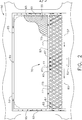
FIG. 2 shows a plan partially cutaway view of a screen according to the present invention; -
FIG. 3 shows a side cutaway view of the screen and an associated air duct taken along line 3-3 shown inFIG. 2 ; -
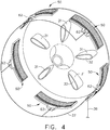
FIG. 4 shows a radially expanded view of a set of screens with sections of an associated engine and a manifold; -
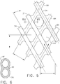
FIG. 5 shows a section of a heated screen; and -
FIG. 6 shows a section of an intersection of two tubes in a heated screen. - Referring to the drawings wherein identical reference numerals denote the same elements throughout the various views,
FIG. 1 shows anengine 12 that includes at least onescreen 50 arranged in ascreen assembly 38 such that the plurality ofscreens 50 each cover anair intake inlet 34. Thescreens 50 each include at least a portion that is heated with air that comes from the compressor section of theengine 12. Theengine 12 also includes apropeller assembly 14, a pair ofexhausts 22, and amounting block 28. In the illustrated embodiment theengine 12 is a turboprop aircraft engine. In other embodiments theengine 12 could be configured for use in marine and industrial applications. - Referring now to
fig. 2 , a section of thescreen assembly 38 is shown such that anexemplar screen 50 is presented in plan view with sections cutaway. Thescreen 50 includes aframe 53 configured to supportunheated mesh 55 and a heatedmesh assembly 70. In the illustrated embodiment, theframe 53 is of tubular construction and includes aheader 57, afirst side duct 61, asecond side duct 62, anintermediate duct 67, and adistal duct 58. Theintermediate duct 67 stretches between, and fluidly connects, thefirst side duct 61 and thesecond side duct 62. Theintermediate duct 67, portions of thefirst side duct 61 and thesecond side duct 62, and thedistal duct 58 are configured to support theunheated mesh 55. Theunheated mesh 55 is configured to allow air from the outside of theengine 12 through theair intake inlet 34 and into theair intake duct 32 while preventing foreign object debris (FOD) from entering theair intake duct 32. Theheader 57, portions of theside duct 61 and thesecond side duct 62, and theintermediate duct 67 are configured to support the heatedmesh assembly 70. - As illustrated, the
frame 53 is generally comprised of hollow, tubular components. These components are configured to provide passageways for heated air. Aninlet 63 is positioned inframe 53 along theheader 57. Theinlet 63 is configured to be fluidly connected to thebleed line 36 via amanifold 37 as illustrated infig. 4 . Theheader 57 is configured to distribute heated air or gas from thecompressor section 39 of theengine 12 around theframe 53 such that theframe 53 is heated. A plurality ofdischarge outlet 65 are formed in thefate frame 53 and release hot air from theframe 53 into theair intake duct 32. - Thus the
header 57, thefirst side duct 61, thesecond side duct 62, and thedistal duct 58 together are configured to fluidly connect theinlet 63 to the plurality ofdischarge outlets 65. Theheader 57 is also configured to distribute hot air to the heatedmesh assembly 70. Referring now toFIGS. 2 and3 , the heatedmesh assembly 70 includes afirst tier 73 offirst tier tubes 74 that is positioned in contact with a second-tier 83 of second-tier tubes 74. - Each
first tier tube 74 has a first tier tube entry 75 and a firsttier tube exit 77. Eachfirst tier tube 74 defines at least a portion of a pathway that fluidly connects theheader 57 to theintermediate duct 67. With regard to the majority of thefirst tier tubes 74, the entry end 75 is attached to theheader 57 and the first tiertube exit end 77 is attached to theintermediate duct 67 for the majority of thefirst tier tubes 74. As shown inFIG. 2 , some of thefirst tier tubes 74 do not have an entry end 75 connected to theheader 57 but instead have the entry end 75 connected to thefirst side duct 61. In addition, some of thefirst tier tubes 74 do not have anexit end 77 attached to theintermediate duct 67 but instead have theexit end 77 attached to thesecond side duct 62. - Likewise, each second-
tier tube 84 has a second-tier tube entry 85 and a secondtier tube exit 87. Eachsecond tube 84 defines at least a portion of a pathway that fluidly connects theheader 57 to one of thefirst side duct 61 and thesecond side duct 62. With regard to the majority of the second-tier tubes 84, the entry end 85 is attached to theheader 57 and the second tiertube exit end 87 is attached to theintermediate duct 67 for the majority of the second-tier tubes 84. As shown inFIG. 2 , some of the second-tier tubes 84 do not have an entry end 85 connected to theheader 57 but instead have the entry end 85 connected to theside duct 62. In addition, some of the second-tier tubes 84 do not have anexit end 87 attached to theintermediate duct 67 but instead have theexit end 87 attached to thefirst side duct 61. - Referring now to
FIG. 5 and FIG. 6 , the heatedmesh assembly 70 and theframe 53 of thescreen 50 are formed utilizing advanced manufacturing techniques in a unitary or monolithic piece preferably. Theunheated mesh 55 of thescreen 50 can be formed together with the other components of thescreen 50 as a unitary or monolithic piece. Alternatively, theunheated mesh 55 can be positioned within and attached to theframe 53 which is can figured to receive it after the heatedmesh assembly 70 and theframe 53 are formed together as can be seen in the 6, where second-tier tubes 84 crossfirst tier tubes 74 they share a common wall atintersection 92. - Continuing to refer to
FIGS. 2 andFIG. 5 , a plurality ofscreen openings 94 are defined by theintersections 92 and portions of thefirst tier tubes 74 and the second-tier tubes 84.Openings 94 are sized such that FOD above a predetermined size and shape cannot pass through. In addition, the number ofopenings 94 in eachscreen 50 is also chosen to allow a predetermined airflow throughscreen 50. It is believed that the tubular construction of portions of thescreen 50 provide additional strength with less weight than similarly sized solid components provide. - Referring now to
FIG. 4 , which shows thescreen assembly 38 in a radially exploded view including partial sections of thestruts 31. As shown in the illustrated embodiment, thescreen assembly 38 includes a plurality of thescreens 50. Thescreens 50 are radially distributed around theengine 12 and each of thescreens 50 are positioned over anair intake inlet 34 of anair intake duct 32. Theair intake duct 32 is is defined by astrut 31. - As described above, each
screen 50 includes aninlet 63. Each of theinlets 63 are fluidly connected to acompressor section 39 of theengine 12 via amanifold 37 and ableed line 36. It should be appreciated that in other embodiments, each of theinlets 63 can be connected directly to thecompressor section 39 of theengine 12 via an individual bleed line. In these embodiments, there is no manifold positioned between the bleed line and theinlet 63. - The present invention can be better understood by a description of the operation thereof. When the
engine 12 is operated, heat is generated. Hot air from thecompressor section 39 is forced through thebleed line 36 and the manifold 37 to each of thescreens 50. At eachscreen 50, the hot air is conducted through theinlet 63 and along theheader 57. It should be appreciated that thescreen 50 is configured such that air flowing through pathways defined by thescreen 50 such as theheader 57 in theheated mesh assembly 70 is distributed in a predetermined manner among the different components. In this regard hot-air is distributed generally throughout theheated mesh assembly 70 and theframe 53. Heat from the air is conducted through the walls of theheated mesh assembly 70 and theframe 53. In this manner, heat from the air derived from thecompressor section 39 of theengine 12 heats the surface and surrounding areas of eachscreen 50 such that ice does not form on the heated mesh assembly providing anti-icing capabilities to eachscreen 50. Air that is flowing through thescreen 50 exits screen 50 through one of thedischarge outlet 65. The air is then directed into theair intake duct 32 and back to thecompressor section 39. - The present invention has advantages over the prior art. The present invention provides an efficient and cost-effective method for providing engine anti-icing and deicing functionality to an air intake inlet on aviation engines and other products. Unique features of this invention include active prevention of ice accumulation at the air intake inlet combined with FOD protection at the air intake inlet. The present invention provides for utilizing existing thermal energy to provide efficient and cost-effective anti-icing. New engine architectures require more robust is the price prevention at air intake inlets on aviation engines and apparatus of the present invention is robust compared to conventional deicing and FOD prevention and thus able to meet regulation requirements.
- The foregoing has described an apparatus and a method for providing anti-icing measures to an air intake inlet on an aviation engine while protecting the inlet from FOD and all of the features disclosed in this specification (including any accompanying claims, abstract and drawings), and/or all of the steps of any method or process so disclosed, may be combined in any combination, except combinations where at least some of such features and/or steps are mutually exclusive.
- Each feature disclosed in this specification (including any accompanying claims, abstract and drawings) may be replaced by alternative features serving the same, equivalent or similar purpose, unless expressly stated otherwise. Thus, unless expressly stated otherwise, each feature disclosed is one example only of a generic series of equivalent or similar features.
- The invention is not restricted to the details of the foregoing embodiment(s). The invention extends to any novel one, or any novel combination, of the features disclosed in this specification (including any accompanying potential points of novelty, abstract and drawings), or to any novel one, or any novel combination, of the steps of any method or process so disclosed.
- Various aspects and embodiments of the present invention are defined by the following numbered clauses:
- 1. An apparatus for providing foreign object debris protection and anti-icing capabilities to an air intake of an aircraft engine, the apparatus comprising;
a frame having at least a portion configured to conduct fluids;
a tube through which different portions of the frame are fluidly connected;
a discharge outlet defined within the frame that is configured to discharge fluid into the air intake;
an inlet defined within the frame; and
and wherein the inlet is fluidly connected to a compressor section of the aircraft engine such that air from the compressor section of the aircraft engine can flow through the inlet, through the tube, and through the discharge outlet, to return to the compressor section of the aircraft engine. - 2. The apparatus according to clause 1, further comprising a plurality of tubes positioned within the frame.
- 3. The apparatus according to any preceding clause, wherein the frame is configured to support a mesh assembly formed of the tubes.
- 4. The apparatus according to any preceding clause, wherein the frame is also configured to support a mesh that is not configured to be heated.
- 5. The apparatus according to any preceding clause, wherein the frame is configured to be heated by hot air from the compressor section around its perimeter.
- 6. The apparatus according to any preceding clause, wherein the tubes are arranged in a tier and are positioned generally parallel to each other.
- 7. The apparatus according to any preceding clause, wherein the tubes are arranged in two tiers such that the tubes in each tier are parallel to tubes also in that tier and the tubes in each tier cross tubes of the other tier to form a mesh.
- 8. The apparatus according to any preceding clause, wherein the mesh is configured to prevent foreign object debris from entering the air intake of the engine.
- 9. The apparatus according to any preceding clause, wherein the tubes are in a first-tier and solid wire links are positioned in a second-tier such that the first year and the second tier together define a mesh.
- 10. A method for providing anti-icing capabilities to the air intake of an aircraft engine wherein the aircraft intake is covered by mesh having at least a portion thereof configured to conduct fluids, the method comprising the steps of:
- conducting heated air from a compressor section of the aircraft engine;
- conducting the heated air through the portion of mesh configured to conduct fluids;
- conducting heat through the mesh;
- elevating the temperature of the mesh; and
- returning the air to the compressor section of the aircraft engine.
- 11. The method according to any preceding clause, wherein the mesh includes a plurality of tubes positioned within a frame.
- 12. The apparatus according to any preceding clause, wherein the frame is configured to support a mesh assembly formed of the tubes.
- 13. The apparatus according to any preceding clause, wherein the frame is configured to be heated by hot air from the compressor section around its perimeter.
- 14. The apparatus according to any preceding clause, wherein the tubes are arranged in two tiers such that the tubes in each tier are parallel to tubes also in that tier and the tubes in each tier cross tubes of the other tier to form a mesh.
- 15. The apparatus according to any preceding clause, wherein the mesh is configured to prevent foreign object debris from entering the air intake of the engine.
- 16. The apparatus according to any preceding clause, wherein the tubes are in a first-tier and solid wire links are positioned in a second-tier such that the first tier and the second tier together define a mesh.
- 17. An engine comprising:
- a plurality of mesh screens formed of tubes that form at least a portion of the fluidly conductive circuit that includes the compressor section of the engine, the mesh screens, and an air intake portion of the engine.
- 18. The engine according to any preceding clause, wherein the plurality of mesh screens are arranged in an array such that each screen is positioned over an associated air intake.
- 19. The engine according to any preceding clause, wherein each of the mesh screens are fluidly connected with the compressor section of the engine via a bleed line.
- 20. The engine according to any preceding clause, wherein each of them mesh screens are fluidly connected to a manifold which is fluidly connected via a single bleed line to the compressor section of the engine.
Claims (15)
- A method for providing anti-icing capabilities to the air intake (38) of an aircraft engine (12) wherein the aircraft intake is covered by mesh (50) having at least a portion thereof configured to conduct fluids, the method comprising the steps of:conducting heated air from a compressor section (39) of the aircraft engine (12);conducting the heated air through the portion of mesh (50) configured to conduct fluids;conducting heat through the mesh (50);elevating the temperature of the mesh (50) such that ice does not form on the mesh (50); andreturning the air to the compressor section (39) of the aircraft engine (12).
- The method according to claim 1, wherein the mesh includes a plurality of tubes (74) positioned within a frame (53).
- The method according to claim 2, wherein the frame (53) is configured to support a mesh assembly (70) formed of the tubes (74).
- The method according to either of claim 2 or 3, wherein the frame (53) is configured to be heated by hot air from the compressor section (39) around its perimeter.
- The method according to any of claims 2 to 4, wherein the tubes (74) are arranged in two tiers such that the tubes (74) in each tier are parallel to tubes (74) also in that tier and the tubes (74) in each tier cross tubes (74) of the other tier to form a mesh (70).
- The method according to any preceding claim, wherein the mesh (70) is configured to prevent foreign object debris from entering the air intake of the engine (12).
- The method according to claim 2 or any claim dependent thereon, wherein the tubes (74) are in a first-tier and solid wire links are positioned in a second-tier (83) such that the first tier (73) and the second tier (83) together define a mesh (70).
- An engine (12) comprising:a plurality of mesh screens (38) formed of tubes (74) that form at least a portion of the fluidly conductive circuit that includes the compressor section (39) of the engine (12), the mesh screens (70), and an air intake (34) portion of the engine (12).
- The engine (12) according to claim 8, wherein the plurality of mesh screens (38) are arranged in an array such that each screen (50) is positioned over an associated air intake (34).
- The engine (12) according to either of claim 8 or 9, wherein each of the mesh screens (50) are fluidly connected with the compressor section (39) of the engine (12) via a bleed line (36).
- The engine (12) according to any of claims 8 to 10, wherein each of the mesh screens (50) are fluidly connected to a manifold (37) which is fluidly connected via a single bleed line (36) to the compressor section (39) of the engine (12).
- The engine (12) according to any of claims 8 to 11, wherein the tubes (74) are arranged in a tier (73) and are positioned generally parallel to each other.
- The engine (12) according to any of claims 8 to 12, wherein the tubes (74, 84) are arranged in two tiers (73, 83) such that the tubes (74, 84) in each tier (73, 83) are parallel to tubes (74, 84) also in that tier (73, 83) and the tubes (74, 84) in each tier (73, 83) cross tubes (74, 84) of the other tier (73, 83) to form a mesh (70).
- The engine (12) according to any of claims 8 to 13, wherein the mesh (70) is configured to prevent foreign object debris from entering the air intake (34) of the engine (12).
- The engine (12) according to any of claims 8 to 14, wherein the tubes (74) are in a first-tier (73) and solid wire links are positioned in a second-tier (83) such that the first year and the second tier together define a mesh (70).
Applications Claiming Priority (1)
| Application Number | Priority Date | Filing Date | Title |
|---|---|---|---|
| US15/072,662 US10450954B2 (en) | 2016-03-17 | 2016-03-17 | Internally heated engine inlet screen for aircraft engines |
Publications (1)
| Publication Number | Publication Date |
|---|---|
| EP3219958A1 true EP3219958A1 (en) | 2017-09-20 |
Family
ID=58266983
Family Applications (1)
| Application Number | Title | Priority Date | Filing Date |
|---|---|---|---|
| EP17160426.7A Withdrawn EP3219958A1 (en) | 2016-03-17 | 2017-03-10 | Internally heated engine inlet screen for aircraft engines |
Country Status (6)
| Country | Link |
|---|---|
| US (1) | US10450954B2 (en) |
| EP (1) | EP3219958A1 (en) |
| JP (1) | JP6420858B2 (en) |
| CN (1) | CN107201950B (en) |
| BR (1) | BR102017004581A2 (en) |
| CA (1) | CA2959692C (en) |
Cited By (2)
| Publication number | Priority date | Publication date | Assignee | Title |
|---|---|---|---|---|
| EP3444446A1 (en) * | 2017-08-14 | 2019-02-20 | General Electric Company | Inlet frame for a gas turbine engine |
| US10830135B2 (en) | 2017-08-14 | 2020-11-10 | General Electric Company Polska sp. z o.o | Inlet frame for a gas turbine engine |
Families Citing this family (9)
| Publication number | Priority date | Publication date | Assignee | Title |
|---|---|---|---|---|
| PL420326A1 (en) * | 2017-01-27 | 2018-07-30 | General Electric Company Polska Spolka Z Ograniczona Odpowiedzialnoscia | Intake shield for aircraft engines |
| JP7011784B2 (en) | 2017-08-30 | 2022-02-10 | 日本電気株式会社 | Iris collation system, iris collation method and storage medium |
| RU187080U1 (en) * | 2018-05-03 | 2019-02-18 | Публичное акционерное общество "Авиационная холдинговая компания "Сухой" | AIR INTAKE PROTECTIVE DEVICE |
| US11359543B2 (en) * | 2019-06-07 | 2022-06-14 | Raytheon Technologies Corporation | Attritable engine additively manufactured inlet cap |
| US12479587B2 (en) | 2020-12-21 | 2025-11-25 | General Electric Company Polska Sp. Z O.O. | Skeleton screen for an air intake portion of a machine |
| CN115370482B (en) * | 2022-10-24 | 2023-03-07 | 成都纵横大鹏无人机科技有限公司 | Air inlet device and air inlet method for aircraft |
| US12241412B1 (en) * | 2023-10-05 | 2025-03-04 | Pratt & Whitney Canada Corp. | Inlet guard screen for an inlet of an aircraft engine |
| US20250115366A1 (en) * | 2023-10-05 | 2025-04-10 | Pratt & Whitney Canada Corp. | Circumferentially tailored inlet guard for an aircraft engine inlet |
| US12276227B1 (en) | 2023-10-23 | 2025-04-15 | General Electric Company | Turbine engine screen |
Citations (5)
| Publication number | Priority date | Publication date | Assignee | Title |
|---|---|---|---|---|
| US2663993A (en) * | 1945-10-10 | 1953-12-29 | Westinghouse Electric Corp | Deicing apparatus |
| US2680345A (en) * | 1951-08-30 | 1954-06-08 | A V Roe Canada Ltd | Gas turbine engine intake deicing and screen |
| US20020179773A1 (en) * | 1999-11-23 | 2002-12-05 | Breer Marlin D. | Method and apparatus for aircraft inlet ice protection |
| US20080307769A1 (en) * | 2007-06-18 | 2008-12-18 | Honeywell International, Inc. | Gas turbine engine anti-ice formation device and system |
| US20090241552A1 (en) * | 2008-03-26 | 2009-10-01 | Alstom Technologies, Ltd., Llc | Utilizing inlet bleed heat to improve mixing and engine turndown |
Family Cites Families (15)
| Publication number | Priority date | Publication date | Assignee | Title |
|---|---|---|---|---|
| US2764390A (en) | 1954-04-01 | 1956-09-25 | Gen Electric | Anti-icing device |
| US3421296A (en) * | 1966-11-15 | 1969-01-14 | United Aircraft Corp | Engine inlet air particle separator |
| US3925979A (en) | 1973-10-29 | 1975-12-16 | Gen Electric | Anti-icing system for a gas turbine engine |
| US3981466A (en) | 1974-12-23 | 1976-09-21 | The Boeing Company | Integrated thermal anti-icing and environmental control system |
| US4328666A (en) | 1980-06-25 | 1982-05-11 | General Electric Company | Heat recovery anti-icing system |
| US4760978A (en) | 1986-11-19 | 1988-08-02 | Cox & Company, Inc. | Ice-free screen for protecting engines from damage caused by foreign bodies in the intake airstream |
| US5560195A (en) | 1995-02-13 | 1996-10-01 | General Electric Co. | Gas turbine inlet heating system using jet blower |
| US6027304A (en) | 1998-05-27 | 2000-02-22 | General Electric Co. | High pressure inlet bleed heat system for the compressor of a turbine |
| US6685425B2 (en) | 2002-06-26 | 2004-02-03 | General Electric Company | Inlet bleed heater for heating inlet air to a compressor and methods of fabricating and transporting the heater |
| JP5232844B2 (en) | 2003-08-21 | 2013-07-10 | 株式会社荏原製作所 | Plating equipment |
| JP4625726B2 (en) | 2005-06-28 | 2011-02-02 | 株式会社竹中工務店 | Piping burial structure for heat exchange of underground heat storage system and burial method |
| US7811050B2 (en) | 2006-12-28 | 2010-10-12 | General Electric Company | Operating line control of a compression system with flow recirculation |
| US8844258B2 (en) | 2011-11-23 | 2014-09-30 | General Electric Company | Systems and methods for de-icing a gas turbine engine inlet screen and dehumidifying inlet air filters |
| US9067679B2 (en) | 2011-12-30 | 2015-06-30 | Aerospace Filtration Systems, Inc. | Heated screen for air intake of aircraft engines |
| DE102014111697A1 (en) * | 2013-08-27 | 2015-03-05 | General Electric Company | Systems and methods for defrosting a gas turbine inlet screen and for dehumidifying air inlet filters |
-
2016
- 2016-03-17 US US15/072,662 patent/US10450954B2/en active Active
-
2017
- 2017-03-02 CA CA2959692A patent/CA2959692C/en active Active
- 2017-03-07 JP JP2017042310A patent/JP6420858B2/en not_active Expired - Fee Related
- 2017-03-08 BR BR102017004581-1A patent/BR102017004581A2/en not_active IP Right Cessation
- 2017-03-10 EP EP17160426.7A patent/EP3219958A1/en not_active Withdrawn
- 2017-03-17 CN CN201710160376.2A patent/CN107201950B/en active Active
Patent Citations (5)
| Publication number | Priority date | Publication date | Assignee | Title |
|---|---|---|---|---|
| US2663993A (en) * | 1945-10-10 | 1953-12-29 | Westinghouse Electric Corp | Deicing apparatus |
| US2680345A (en) * | 1951-08-30 | 1954-06-08 | A V Roe Canada Ltd | Gas turbine engine intake deicing and screen |
| US20020179773A1 (en) * | 1999-11-23 | 2002-12-05 | Breer Marlin D. | Method and apparatus for aircraft inlet ice protection |
| US20080307769A1 (en) * | 2007-06-18 | 2008-12-18 | Honeywell International, Inc. | Gas turbine engine anti-ice formation device and system |
| US20090241552A1 (en) * | 2008-03-26 | 2009-10-01 | Alstom Technologies, Ltd., Llc | Utilizing inlet bleed heat to improve mixing and engine turndown |
Cited By (4)
| Publication number | Priority date | Publication date | Assignee | Title |
|---|---|---|---|---|
| EP3444446A1 (en) * | 2017-08-14 | 2019-02-20 | General Electric Company | Inlet frame for a gas turbine engine |
| EP3444447A1 (en) * | 2017-08-14 | 2019-02-20 | General Electric Company | Inlet frame for a gas turbine engine |
| EP3699403A1 (en) * | 2017-08-14 | 2020-08-26 | General Electric Company | Method for manufacturing an inlet frame for a gas turbine engine |
| US10830135B2 (en) | 2017-08-14 | 2020-11-10 | General Electric Company Polska sp. z o.o | Inlet frame for a gas turbine engine |
Also Published As
| Publication number | Publication date |
|---|---|
| CA2959692A1 (en) | 2017-09-17 |
| JP6420858B2 (en) | 2018-11-07 |
| BR102017004581A2 (en) | 2017-12-12 |
| CN107201950A (en) | 2017-09-26 |
| JP2017165403A (en) | 2017-09-21 |
| CN107201950B (en) | 2020-07-14 |
| CA2959692C (en) | 2020-11-03 |
| US20170268424A1 (en) | 2017-09-21 |
| US10450954B2 (en) | 2019-10-22 |
Similar Documents
| Publication | Publication Date | Title |
|---|---|---|
| CA2959692C (en) | Internally heated engine inlet screen for aircraft engines | |
| US8540185B2 (en) | Modular air inlet lip with electric defrosting for a turbojet pod | |
| US10173780B2 (en) | Aircraft liquid heat exchanger anti-icing system | |
| RU2492115C2 (en) | Turbojet nacelle air intake edge | |
| US10144520B2 (en) | De-icing system with thermal management | |
| CN106762147B (en) | A kind of engine anti-icing system | |
| CN110121463B (en) | Assembly and method for conditioning engine heated air in an aircraft | |
| EP2963248A1 (en) | Method and system for radial tubular duct heat exchangers | |
| JP6766197B2 (en) | Equipment for deicing the separator nose of aircraft turbine engines | |
| JP2006336650A (en) | Modular fan inlet ice protection system | |
| JP2015143101A (en) | Anti-icing system and method for preventing ice accumulation | |
| CN106959034A (en) | Heat Exchangers for Embedded Engine Applications | |
| CN106959035A (en) | Heat Exchangers for Embedded Engine Applications: Transverse Duct Sections | |
| EP3397368B1 (en) | Vehicle provided, at the intake, with an air filter provided with a heating device | |
| CN108361110B (en) | Inlet mesh screen for aircraft engines | |
| US3057154A (en) | De-icer system for a gas turbine engine | |
| US9182175B2 (en) | Anti-icing heat exchanger | |
| CN103958347A (en) | System and method for cooling an aircraft wing | |
| CA2890421A1 (en) | Aircraft propelling assembly including a duct forming a thermal barrier integrated in the caisson of the rigid structure of the engine mounting system | |
| CN102317160A (en) | Deicing equipment, especially for aircraft engine nacelles | |
| CN110186306B (en) | Heat exchanger assembly | |
| US20150143812A1 (en) | Exhaust Plume Cooling | |
| CN106032168B (en) | A kind of anti-icing and extinguishing device and method of aircraft | |
| CN105352737B (en) | A kind of ground based IR test platform | |
| CN104395193A (en) | Electrical heating unit for a de-icing device |
Legal Events
| Date | Code | Title | Description |
|---|---|---|---|
| PUAI | Public reference made under article 153(3) epc to a published international application that has entered the european phase |
Free format text: ORIGINAL CODE: 0009012 |
|
| STAA | Information on the status of an ep patent application or granted ep patent |
Free format text: STATUS: THE APPLICATION HAS BEEN PUBLISHED |
|
| AK | Designated contracting states |
Kind code of ref document: A1 Designated state(s): AL AT BE BG CH CY CZ DE DK EE ES FI FR GB GR HR HU IE IS IT LI LT LU LV MC MK MT NL NO PL PT RO RS SE SI SK SM TR |
|
| AX | Request for extension of the european patent |
Extension state: BA ME |
|
| STAA | Information on the status of an ep patent application or granted ep patent |
Free format text: STATUS: REQUEST FOR EXAMINATION WAS MADE |
|
| 17P | Request for examination filed |
Effective date: 20180320 |
|
| RBV | Designated contracting states (corrected) |
Designated state(s): AL AT BE BG CH CY CZ DE DK EE ES FI FR GB GR HR HU IE IS IT LI LT LU LV MC MK MT NL NO PL PT RO RS SE SI SK SM TR |
|
| STAA | Information on the status of an ep patent application or granted ep patent |
Free format text: STATUS: EXAMINATION IS IN PROGRESS |
|
| 17Q | First examination report despatched |
Effective date: 20181210 |
|
| GRAP | Despatch of communication of intention to grant a patent |
Free format text: ORIGINAL CODE: EPIDOSNIGR1 |
|
| STAA | Information on the status of an ep patent application or granted ep patent |
Free format text: STATUS: GRANT OF PATENT IS INTENDED |
|
| RIC1 | Information provided on ipc code assigned before grant |
Ipc: B64D 33/02 20060101ALI20200626BHEP Ipc: F02C 7/055 20060101ALI20200626BHEP Ipc: F02C 6/08 20060101ALI20200626BHEP Ipc: B64D 15/04 20060101ALI20200626BHEP Ipc: F02C 7/047 20060101AFI20200626BHEP |
|
| INTG | Intention to grant announced |
Effective date: 20200730 |
|
| STAA | Information on the status of an ep patent application or granted ep patent |
Free format text: STATUS: THE APPLICATION IS DEEMED TO BE WITHDRAWN |
|
| 18D | Application deemed to be withdrawn |
Effective date: 20201210 |