EP3219925B1 - Aube composite - Google Patents
Aube composite Download PDFInfo
- Publication number
- EP3219925B1 EP3219925B1 EP17167001.1A EP17167001A EP3219925B1 EP 3219925 B1 EP3219925 B1 EP 3219925B1 EP 17167001 A EP17167001 A EP 17167001A EP 3219925 B1 EP3219925 B1 EP 3219925B1
- Authority
- EP
- European Patent Office
- Prior art keywords
- composite
- resin
- layer
- woven
- structural core
- Prior art date
- Legal status (The legal status is an assumption and is not a legal conclusion. Google has not performed a legal analysis and makes no representation as to the accuracy of the status listed.)
- Active
Links
- 239000002131 composite material Substances 0.000 title claims description 40
- 229920005989 resin Polymers 0.000 claims description 27
- 239000011347 resin Substances 0.000 claims description 27
- 239000000853 adhesive Substances 0.000 claims description 24
- 230000001070 adhesive effect Effects 0.000 claims description 24
- 230000003628 erosive effect Effects 0.000 claims description 15
- 239000004814 polyurethane Substances 0.000 claims description 8
- 229920002635 polyurethane Polymers 0.000 claims description 7
- 238000000034 method Methods 0.000 claims description 5
- OKTJSMMVPCPJKN-UHFFFAOYSA-N Carbon Chemical compound [C] OKTJSMMVPCPJKN-UHFFFAOYSA-N 0.000 claims description 4
- 229910052799 carbon Inorganic materials 0.000 claims description 4
- 239000003822 epoxy resin Substances 0.000 claims description 4
- 238000004519 manufacturing process Methods 0.000 claims description 4
- 229920000647 polyepoxide Polymers 0.000 claims description 4
- 229920001187 thermosetting polymer Polymers 0.000 claims description 3
- 239000011521 glass Substances 0.000 claims 1
- 239000010410 layer Substances 0.000 description 52
- 239000000463 material Substances 0.000 description 10
- 239000002184 metal Substances 0.000 description 7
- 229910052751 metal Inorganic materials 0.000 description 7
- 238000013016 damping Methods 0.000 description 6
- 239000002344 surface layer Substances 0.000 description 5
- 239000004593 Epoxy Substances 0.000 description 4
- PXHVJJICTQNCMI-UHFFFAOYSA-N Nickel Chemical compound [Ni] PXHVJJICTQNCMI-UHFFFAOYSA-N 0.000 description 4
- 238000005452 bending Methods 0.000 description 4
- 230000032798 delamination Effects 0.000 description 4
- 239000012790 adhesive layer Substances 0.000 description 3
- 230000008901 benefit Effects 0.000 description 3
- 239000011159 matrix material Substances 0.000 description 3
- 238000004132 cross linking Methods 0.000 description 2
- 239000000835 fiber Substances 0.000 description 2
- 238000007667 floating Methods 0.000 description 2
- 230000003116 impacting effect Effects 0.000 description 2
- 238000005470 impregnation Methods 0.000 description 2
- 229910052759 nickel Inorganic materials 0.000 description 2
- 230000008569 process Effects 0.000 description 2
- 230000009467 reduction Effects 0.000 description 2
- 230000004044 response Effects 0.000 description 2
- 239000002904 solvent Substances 0.000 description 2
- KXGFMDJXCMQABM-UHFFFAOYSA-N 2-methoxy-6-methylphenol Chemical compound [CH]OC1=CC=CC([CH])=C1O KXGFMDJXCMQABM-UHFFFAOYSA-N 0.000 description 1
- RTAQQCXQSZGOHL-UHFFFAOYSA-N Titanium Chemical compound [Ti] RTAQQCXQSZGOHL-UHFFFAOYSA-N 0.000 description 1
- 230000004913 activation Effects 0.000 description 1
- 230000001464 adherent effect Effects 0.000 description 1
- 238000004026 adhesive bonding Methods 0.000 description 1
- 239000011248 coating agent Substances 0.000 description 1
- 238000000576 coating method Methods 0.000 description 1
- 238000007598 dipping method Methods 0.000 description 1
- 229920001971 elastomer Polymers 0.000 description 1
- 239000000806 elastomer Substances 0.000 description 1
- 239000003365 glass fiber Substances 0.000 description 1
- 239000003292 glue Substances 0.000 description 1
- 238000001802 infusion Methods 0.000 description 1
- 239000007788 liquid Substances 0.000 description 1
- 239000007769 metal material Substances 0.000 description 1
- 230000007935 neutral effect Effects 0.000 description 1
- 150000002825 nitriles Chemical class 0.000 description 1
- 239000011368 organic material Substances 0.000 description 1
- 229920001568 phenolic resin Polymers 0.000 description 1
- 239000005011 phenolic resin Substances 0.000 description 1
- 230000001902 propagating effect Effects 0.000 description 1
- 230000001681 protective effect Effects 0.000 description 1
- 238000009745 resin transfer moulding Methods 0.000 description 1
- 238000004901 spalling Methods 0.000 description 1
- 238000005507 spraying Methods 0.000 description 1
- 239000000758 substrate Substances 0.000 description 1
- 239000010936 titanium Substances 0.000 description 1
- 229910052719 titanium Inorganic materials 0.000 description 1
- 239000002347 wear-protection layer Substances 0.000 description 1
Images

Classifications
-
- F—MECHANICAL ENGINEERING; LIGHTING; HEATING; WEAPONS; BLASTING
- F01—MACHINES OR ENGINES IN GENERAL; ENGINE PLANTS IN GENERAL; STEAM ENGINES
- F01D—NON-POSITIVE DISPLACEMENT MACHINES OR ENGINES, e.g. STEAM TURBINES
- F01D5/00—Blades; Blade-carrying members; Heating, heat-insulating, cooling or antivibration means on the blades or the members
- F01D5/12—Blades
- F01D5/28—Selecting particular materials; Particular measures relating thereto; Measures against erosion or corrosion
- F01D5/282—Selecting composite materials, e.g. blades with reinforcing filaments
-
- F—MECHANICAL ENGINEERING; LIGHTING; HEATING; WEAPONS; BLASTING
- F01—MACHINES OR ENGINES IN GENERAL; ENGINE PLANTS IN GENERAL; STEAM ENGINES
- F01D—NON-POSITIVE DISPLACEMENT MACHINES OR ENGINES, e.g. STEAM TURBINES
- F01D5/00—Blades; Blade-carrying members; Heating, heat-insulating, cooling or antivibration means on the blades or the members
- F01D5/12—Blades
- F01D5/14—Form or construction
- F01D5/147—Construction, i.e. structural features, e.g. of weight-saving hollow blades
-
- F—MECHANICAL ENGINEERING; LIGHTING; HEATING; WEAPONS; BLASTING
- F01—MACHINES OR ENGINES IN GENERAL; ENGINE PLANTS IN GENERAL; STEAM ENGINES
- F01D—NON-POSITIVE DISPLACEMENT MACHINES OR ENGINES, e.g. STEAM TURBINES
- F01D5/00—Blades; Blade-carrying members; Heating, heat-insulating, cooling or antivibration means on the blades or the members
- F01D5/12—Blades
- F01D5/28—Selecting particular materials; Particular measures relating thereto; Measures against erosion or corrosion
-
- Y—GENERAL TAGGING OF NEW TECHNOLOGICAL DEVELOPMENTS; GENERAL TAGGING OF CROSS-SECTIONAL TECHNOLOGIES SPANNING OVER SEVERAL SECTIONS OF THE IPC; TECHNICAL SUBJECTS COVERED BY FORMER USPC CROSS-REFERENCE ART COLLECTIONS [XRACs] AND DIGESTS
- Y02—TECHNOLOGIES OR APPLICATIONS FOR MITIGATION OR ADAPTATION AGAINST CLIMATE CHANGE
- Y02T—CLIMATE CHANGE MITIGATION TECHNOLOGIES RELATED TO TRANSPORTATION
- Y02T50/00—Aeronautics or air transport
- Y02T50/60—Efficient propulsion technologies, e.g. for aircraft
-
- Y—GENERAL TAGGING OF NEW TECHNOLOGICAL DEVELOPMENTS; GENERAL TAGGING OF CROSS-SECTIONAL TECHNOLOGIES SPANNING OVER SEVERAL SECTIONS OF THE IPC; TECHNICAL SUBJECTS COVERED BY FORMER USPC CROSS-REFERENCE ART COLLECTIONS [XRACs] AND DIGESTS
- Y10—TECHNICAL SUBJECTS COVERED BY FORMER USPC
- Y10T—TECHNICAL SUBJECTS COVERED BY FORMER US CLASSIFICATION
- Y10T428/00—Stock material or miscellaneous articles
- Y10T428/24—Structurally defined web or sheet [e.g., overall dimension, etc.]
- Y10T428/24942—Structurally defined web or sheet [e.g., overall dimension, etc.] including components having same physical characteristic in differing degree
Definitions
- the present invention relates to composite aerofoils and in particular composite aerofoils for aircraft and particular aerofoils in a turbine engine.
- Aerospace composite components tend to be constructed from unidirectional carbon fibre laid up ply-by-ply into a laminate and the plies bonded together using a resin.
- the resin may be injected into the preform in a process known as resin transfer moulding (RTM) or may already be present in the plies with the plies being supplied as a pre-impregnated or pre-preg material.
- RTM resin transfer moulding
- the composite then goes through a series of further processes including a heat cycle to cure the resin.
- Aerospace composites may be used to form aerofoils such as blades or vanes in an engine or fuselage components such as wings, struts, rudders etc.
- Any exposed composite aerospace component can be subject to foreign object damage (FOD).
- FOD foreign object damage
- These are usually small mass projectiles (e.g. gravel, bolts, etc.) travelling at relatively high speeds (100-500 m/s).
- the characteristic damage following these events is localised and depends on the severity of the impact. Low energies can result in minor matrix damage adjacent to the impact site. As the energy increases, this damage becomes more widespread. Further increases may result in this damage coalescing and forming delaminations.
- US 4,006,999 discloses a laminated filament composite structure, such as an aerofoil which may be subject to foreign object impact, provided with improved leading edge protection.
- a fine wire mesh layer is partially bonded within the composite structure along its neutral bending axis.
- the wire mesh is clad with a metal such as nickel to provide a leading edge protective device which is firmly anchored within the composite structure.
- DE4443440 discloses a wear (mainly erosion and cavitation) protection layer for components of inorganic non-metallic, metallic and/or organic materials, especially components exposed to impingement and glancing stream wear.
- the wear protection layer consists of: (a) a compact, adherent metal or hard metal layer of 1000-3000 HV hardness, which is adhesively bonded, vapour deposited, electroplated or sprayed onto (b) an elastic layer of uniform or variable thickness according to the surface contour of the component.
- the elastic layer has a thickness of 0.5-3 mm and a Shore A hardness A10 to A90.
- US 3,892,612 discloses a filament composite compressor blade provided with a fine wire mesh subsurface layer around its leading edge, clad with nickel. Internal mesh layers are also incorporated in the blade.
- a composite aerofoil according to claim 1 having a leading edge, a trailing edge a pressure side and a suction side and comprising an outer erosion protection layer along one or both of the pressure side or suction side, a structural core having a plurality of resin impregnated plies of unidirectional fibres, and between the outer erosion protection layer and the structural core a woven composite impregnated with a resin having a lower modulus of elasticity than that of the resin impregnating the plies in the structural core.
- the outer erosion protection layer may have a hardness between Shore A50 and Shore D 60. Preferably the hardness is Shore A 90.
- the outer erosion protection layer may be polyurethane.
- the resin impregnating the structural core may be an epoxy resin.
- the resin impregnating the woven composite may be a thermosetting nitrile phenolic adhesive.
- a method of manufacturing a composite aerofoil according to claim 8 comprising the steps of providing a structural core having a plurality of resin impregnated plies of unidirectional fibres, the resin within the plies having a predetermined modulus of elasticity; providing a woven composite impregnated with a resin having a lower modulus of elasticity than that of the resin impregnating the plies in the structural core; and consolidating the structural core and the woven layer by placing them in contact and applying heat.
- the method may further comprise the step of an erosion protection layer to the woven layer.
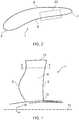
- Figure 1 depicts an exemplary exterior form of an aerofoil 1 in accordance with the present invention which may be used in an axial gas turbine engine.
- Figure 2 is a cross-section of the aerofoil 1 taken through section A-A of Figure 1 .
- the aerofoil has an axially forward leading edge 2 and an axially rearward trailing edge 4.
- the periphery of the aerofoil comprises flanks or sides which extend between the leading edge and training edge: a pressure flank 6 which extends along one side and a suction side 8 which extends along the other side.
- the aerofoil surfaces also extend from the aerofoil platform 12 to the aerofoil tip 10.
- the aerofoil is arranged within the gas turbine engine to rotate about the engine axis 14 in the direction of arrow 16.
- Figure 3 is a section from box 20 of Figure 2 showing part of the internal structure of the aerofoil 1.
- the structure is provided by a plurality of relatively discrete layers which will be described in turn from the outer layer 22 providing the pressure surface 6 through to the blade core 30.
- the outer layer 22 of the exemplary composite blade is an erosion protection layer between 0.1 and 0.5mm thick of a material with a hardness between Shore A 50 and Shore D 60.
- a preferred hardness is around Shore A 90 which is possibly provided by a material such as polyurethane.
- the outer layer can be applied by any suitable method such as spraying or dipping or applying as a film.
- the outer layer is compliant to reduce the peak contact force of any foreign object (FO) impacting the blade and to alleviate the localised damage caused by the FO. It has been found that the likelihood of damage is dictated at least in part by the peak contact force.
- An adhesive layer 24 having a thickness of around 0.1 mm is used to connect the polyurethane erosion protection layer to the rest of the blade.
- Preferred adhesives have high peel strengths, good flexibility, shear strength and have excellent adhesion to epoxy, polyurethane and optionally titanium.
- Two exemplary adhesives which may be used are nitrile phenolic resin that are provided in liquid or film form and known as AF32TM and AF500TM both of which are available from 3MTM as unsupported, thermosetting film adhesive.
- AF32 has an OLS at 75°F (24°C) of 3500 psi (24.1 MPa) and a peel strength measured by a metal/metal floating roller of 55 piw (9.6 N/mm).
- AF500 has an OLS at 75°F (24°C) of 6000 psi (41.4 MPa) and a peel strength of 77 piw (343 N/25mm) measured by a metal/metal floating roller.
- a scrim may be used to control bonding thickness.
- Bonded to the adhesive layer 24 is a woven composite layer 26 with a baseline thickness of 1 ply (around 0.25mm) though other additional plies may be added.
- the weave is provided by carbon or glass fibres laid up in an appropriate pattern e.g. plain weave, 8 harness satin, 4 harness satin or 2 x 2 twill depending on the desired weave property.
- the weave is infused with the same adhesive which joins the weave to the surface layer 22.
- This adhesive is more flexible than the resins conventionally used to infuse composites and which has a lower modulus of elasticity than that of the resin used to make up the structural core 30 of the aerofoil.
- the infusion of the weave with the adhesive material significantly improves the damage tolerance of the structure.
- the infused woven layer inhibits the damage propagating through to the structural core 30.
- the surface layers may become detached when the structure undergoes bending.
- the resilient adhesive is stronger and tougher than a resin that is optimised as a matrix material. This improves the interface strength relative to a resin matrix material and reduces the likelihood of the woven layer becoming detached as the aerofoil bends and any crack propagation into the structural core.
- a further advantage of having a woven layer impregnated with the adhesive situated between the erosion layer 22 and the core 30 introduces a constrained layer damper.
- composite materials have relatively high levels of inherent damping, further reductions in blade response allow thickness reduction and therefore improved weight and aerodynamic performance.
- the woven layer reinforces the adhesive such that under the point of impact the resilient adhesive material thins out and expands due to the poisson's ratio of the material but the presence of the woven layer controls expansion and spreads and dissipates energy and therefore reduces vibration amplitudes.
- the efficiency of this strain-based damping system is improved when the polyurethane layer of stiff material is laid over the top of the elastomer by increasing the shear strain in the damping layer when the substrate is put into bending.
- An adhesive layer 28 with a thickness of less than 0.5mm connects the woven layer 26 with the structural core 30.
- the adhesive is preferably of the same material as used in layer 24 and as the infused material in the woven composite layer.
- the use of the adhesive in the woven composite layer can have sufficient adhesion to make the glue layer 28 redundant which beneficially can reduce the overall thickness of the aerofoil.
- the structural core 30 is provided by a plurality of plies of unidirectional carbon fibres impregnated by an epoxy resin.
- the resin is significantly stiffer that the adhesive impregnating the woven layer and it has been found that gluing a polyurethane outer coating directly to an epoxy impregnated ply of composite can cause delamination due to the relatively large differences in stiffness between the PU layer and the epoxy.
- Using an adhesive with an intermediate stiffness filling woven composite between the two mediates the differences and reduces the possibility of delamination.
- the structural core is initially laid up and manufactured from a series of epoxy pre-impregnated unidirectional tapes.
- the tapes and thus the fibres are arranged in a series of layers with the alignment of the fibres in adjacent layers being different. Alignments than may be used are +45°, -45° and 0° with the angles being measured from the radial span of the blade extending from the platform to the blade tip.
- the woven layer is manufactured separately.
- the viscosity of the adhesive is reduced by addition of a suitable solvent, by controlling the amount of cross-linking in the adhesive or by changing the viscosity of the resin by suitably activation to allow for the impregnation of the woven layer.
- the adhesive is then placed on a tooling surface and the woven layer applied to it. To consolidate the assembly it is held at an elevated temperature and a differential pressure is created between tool and the woven layer. The differential pressure causes the adhesive to flow into the interstices within the composite. After impregnation the cross-linking density of the adhesive is increased or the solvent evaporated to convert the material to a more tacky state to provide an assembly that may be removed from the tooling surface.
- the two are consolidated by placing in direct contact, possibly with a layer of adhesive between them and heated to cure the epoxy resin with the structural core and adhesive within the woven composite and join the two parts together.
- the woven layer is formed first and the pre-impregnated plies of the structural core are laid onto the woven layer and subsequently cured and consolidated.
- the invention described in this application offers a number of advantages, including: improved damage resistance and tolerances for hard body impact, improved protection of the erosion protection layer local to the impact site for soft body impact, improved damping functionality, the integrity of the surface layer is improved during gross bending of the aerofoil and, because of the damping and resistance to damage, a thinner aerofoil is enabled for a given foreign object impact.
Landscapes
- Engineering & Computer Science (AREA)
- Chemical & Material Sciences (AREA)
- Materials Engineering (AREA)
- Mechanical Engineering (AREA)
- General Engineering & Computer Science (AREA)
- Composite Materials (AREA)
- Architecture (AREA)
- Laminated Bodies (AREA)
- Structures Of Non-Positive Displacement Pumps (AREA)
- Reinforced Plastic Materials (AREA)
Claims (9)
- Aube composite (6), l'aube comportant un bord d'attaque (2), un bord de fuite (4), un côté pression (6) et un côté d'aspiration (8) et comprenant :une couche extérieure de protection contre l'érosion (22) le long de l'un ou des deux du côté pression et du côté aspiration,une âme structurale (30) comportant une pluralité d'épaisseurs de fibres unidirectionnelles imprégnées de résine, et caractérisée en ce queentre la couche extérieure de protection contre l'érosion et l'âme structurale est présent un composite tissé (26) imprégné d'une résine ayant un module d'élasticité inférieur à celui de la résine dont sont imprégnées les épaisseurs dans l'âme structurale.
- Aube composite selon la revendication 1, dans laquelle la couche extérieure de protection contre l'érosion a une dureté de Shore A 50 à Shore D 60.
- Aube composite selon la revendication 2, dans laquelle la dureté est de Shore A 90.
- Aube composite selon l'une quelconque des revendications précédentes, dans laquelle la couche extérieure de protection contre l'érosion est en polyuréthane.
- Aube composite selon l'une quelconque des revendications précédentes, dans laquelle la résine dont est imprégnée l'âme structurale est une résine époxyde.
- Aube composite selon l'une quelconque des revendications précédentes, dans laquelle la résine dont est imprégné le composite tissé est un adhésif nitrile phénolique thermodurcissable.
- Aube composite selon l'une quelconque des revendications précédentes, dans laquelle le composite tissé comprend des fibres de verre ou de carbone.
- Procédé de fabrication d'une aube composite selon la revendication 1, comprenant les étapes qui consistent à :fournir l'âme structurale (30) comportant une pluralité d'épaisseurs de fibres unidirectionnelles imprégnées de résine, la résine dans les épaisseurs ayant un module d'élasticité prédéterminé ; fournir un composite tissé (26) imprégné d'une résine ayant un module d'élasticité inférieur à celui de la résine dont sont imprégnées les épaisseurs dans l'âme structurale ; etamalgamer l'âme structurale et la couche tissée en les mettant en contact et en appliquant de la chaleur.
- Procédé selon la revendication 8, comprenant en outre l'étape de fixation d'une couche de protection contre l'érosion à la couche tissée.
Applications Claiming Priority (2)
| Application Number | Priority Date | Filing Date | Title |
|---|---|---|---|
| GBGB1112870.9A GB201112870D0 (en) | 2011-07-27 | 2011-07-27 | Composite aerofoil |
| EP12175963.3A EP2551461A3 (fr) | 2011-07-27 | 2012-07-11 | Aube composite |
Related Parent Applications (1)
| Application Number | Title | Priority Date | Filing Date |
|---|---|---|---|
| EP12175963.3A Division EP2551461A3 (fr) | 2011-07-27 | 2012-07-11 | Aube composite |
Publications (2)
| Publication Number | Publication Date |
|---|---|
| EP3219925A1 EP3219925A1 (fr) | 2017-09-20 |
| EP3219925B1 true EP3219925B1 (fr) | 2020-09-30 |
Family
ID=44652365
Family Applications (2)
| Application Number | Title | Priority Date | Filing Date |
|---|---|---|---|
| EP12175963.3A Withdrawn EP2551461A3 (fr) | 2011-07-27 | 2012-07-11 | Aube composite |
| EP17167001.1A Active EP3219925B1 (fr) | 2011-07-27 | 2012-07-11 | Aube composite |
Family Applications Before (1)
| Application Number | Title | Priority Date | Filing Date |
|---|---|---|---|
| EP12175963.3A Withdrawn EP2551461A3 (fr) | 2011-07-27 | 2012-07-11 | Aube composite |
Country Status (4)
| Country | Link |
|---|---|
| US (2) | US9045991B2 (fr) |
| EP (2) | EP2551461A3 (fr) |
| ES (1) | ES2832613T3 (fr) |
| GB (1) | GB201112870D0 (fr) |
Families Citing this family (17)
| Publication number | Priority date | Publication date | Assignee | Title |
|---|---|---|---|---|
| US9909505B2 (en) * | 2011-07-05 | 2018-03-06 | United Technologies Corporation | Efficient, low pressure ratio propulsor for gas turbine engines |
| GB201305325D0 (en) * | 2013-03-22 | 2013-05-08 | Hexcel Composites Ltd | Composite material |
| FR3049002B1 (fr) * | 2016-03-21 | 2020-01-24 | Safran Aircraft Engines | Pale de turbomachine aeronautique comprenant un element rapporte en materiau composite formant bord de fuite et procede de fabrication d'une telle pale |
| FR3049001B1 (fr) * | 2016-03-21 | 2019-07-12 | Safran Aircraft Engines | Turbomachine aeronautique a helice non carenee munie de pales ayant un element rapporte en materiau composite colle sur leur bord d'attaque |
| US10584740B2 (en) | 2018-02-12 | 2020-03-10 | Schaeffler Technologies AG & Co. KG | Thrust bushing surface layer using directly bonded heat activated nitrile-phenolic adhesive film |
| FR3081914B1 (fr) * | 2018-06-05 | 2020-08-28 | Safran Aircraft Engines | Aube de soufflante en materiau composite avec grand jeu integre |
| FR3087830B1 (fr) * | 2018-10-30 | 2020-10-16 | Safran Aircraft Engines | Aube comprenant une structure en materiau composite et une piece de raidissement metallique |
| FR3095650B1 (fr) * | 2019-05-02 | 2021-04-09 | Safran Aircraft Engines | Procédé de revêtement d’une pièce de turbomachine d’aéronef |
| US11697623B2 (en) * | 2020-06-18 | 2023-07-11 | Rolls-Royce Corporation | Method to produce a ceramic matrix composite with controlled surface characteristics |
| US11833779B2 (en) | 2020-11-20 | 2023-12-05 | General Electric Company | Composite component with oil barrier coating |
| US11655768B2 (en) | 2021-07-26 | 2023-05-23 | General Electric Company | High fan up speed engine |
| US11739689B2 (en) | 2021-08-23 | 2023-08-29 | General Electric Company | Ice reduction mechanism for turbofan engine |
| US11767790B2 (en) | 2021-08-23 | 2023-09-26 | General Electric Company | Object direction mechanism for turbofan engine |
| US11480063B1 (en) | 2021-09-27 | 2022-10-25 | General Electric Company | Gas turbine engine with inlet pre-swirl features |
| US11788465B2 (en) | 2022-01-19 | 2023-10-17 | General Electric Company | Bleed flow assembly for a gas turbine engine |
| US11808281B2 (en) | 2022-03-04 | 2023-11-07 | General Electric Company | Gas turbine engine with variable pitch inlet pre-swirl features |
| US11725526B1 (en) | 2022-03-08 | 2023-08-15 | General Electric Company | Turbofan engine having nacelle with non-annular inlet |
Family Cites Families (14)
| Publication number | Priority date | Publication date | Assignee | Title |
|---|---|---|---|---|
| US3762835A (en) * | 1971-07-02 | 1973-10-02 | Gen Electric | Foreign object damage protection for compressor blades and other structures and related methods |
| US3892612A (en) * | 1971-07-02 | 1975-07-01 | Gen Electric | Method for fabricating foreign object damage protection for rotar blades |
| US4006999A (en) * | 1975-07-17 | 1977-02-08 | The United States Of America As Represented By The Administrator Of The National Aeronautics And Space Administration | Leading edge protection for composite blades |
| US4111606A (en) * | 1976-12-27 | 1978-09-05 | United Technologies Corporation | Composite rotor blade |
| US4810167A (en) * | 1986-12-08 | 1989-03-07 | Hartzell Propeller Inc. | Composite aircraft propeller blade |
| CA2070522A1 (fr) | 1991-07-22 | 1993-01-23 | Jan C. Schilling | Aubes/pales composites pour soufflante |
| DE4443440A1 (de) * | 1994-01-26 | 1995-07-27 | Forschungskuratorium Maschinen | Verschleißschutzschicht und Verfahren zum Auftragen dieser auf Bauteile |
| US5486096A (en) | 1994-06-30 | 1996-01-23 | United Technologies Corporation | Erosion resistant surface protection |
| JPH1054204A (ja) * | 1996-05-20 | 1998-02-24 | General Electric Co <Ge> | ガスタービン用の多構成部翼 |
| US5931641A (en) * | 1997-04-25 | 1999-08-03 | General Electric Company | Steam turbine blade having areas of different densities |
| US7087296B2 (en) * | 2001-11-29 | 2006-08-08 | Saint-Gobain Technical Fabrics Canada, Ltd. | Energy absorbent laminate |
| US7575417B2 (en) * | 2003-09-05 | 2009-08-18 | General Electric Company | Reinforced fan blade |
| US8105042B2 (en) * | 2009-04-06 | 2012-01-31 | United Technologies Corporation | Intermediate-manufactured composite airfoil and methods for manufacturing |
| US8807931B2 (en) * | 2010-01-04 | 2014-08-19 | General Electric Company | System for impact zone reinforcement |
-
2011
- 2011-07-27 GB GBGB1112870.9A patent/GB201112870D0/en not_active Ceased
-
2012
- 2012-07-11 US US13/546,647 patent/US9045991B2/en not_active Ceased
- 2012-07-11 EP EP12175963.3A patent/EP2551461A3/fr not_active Withdrawn
- 2012-07-11 ES ES17167001T patent/ES2832613T3/es active Active
- 2012-07-11 EP EP17167001.1A patent/EP3219925B1/fr active Active
-
2017
- 2017-05-31 US US15/609,918 patent/USRE47696E1/en active Active
Non-Patent Citations (1)
| Title |
|---|
| None * |
Also Published As
| Publication number | Publication date |
|---|---|
| EP2551461A2 (fr) | 2013-01-30 |
| GB201112870D0 (en) | 2011-09-07 |
| EP3219925A1 (fr) | 2017-09-20 |
| US9045991B2 (en) | 2015-06-02 |
| US20130029117A1 (en) | 2013-01-31 |
| EP2551461A3 (fr) | 2016-11-16 |
| ES2832613T3 (es) | 2021-06-10 |
| USRE47696E1 (en) | 2019-11-05 |
Similar Documents
| Publication | Publication Date | Title |
|---|---|---|
| USRE47696E1 (en) | Composite aerofoil | |
| US9751612B2 (en) | Multifunctional composite material including a viscoelastic interlayer | |
| CN105934327B (zh) | 耐腐蚀空气动力整流件 | |
| EP2125344B1 (fr) | Fabrication d'un moulage composite renforce de fibres | |
| US8647070B2 (en) | Reinforced composite aerofoil blade | |
| AU2005289392B2 (en) | Thin ply laminates | |
| US7575417B2 (en) | Reinforced fan blade | |
| US8322657B2 (en) | Panel with impact protection membrane | |
| US20160032939A1 (en) | Airfoil structures | |
| JP2006505655A (ja) | 形状記憶合金で強化したポリマー複合体構造およびその製造方法 | |
| US20080087768A1 (en) | Aircraft component | |
| WO2006072758A2 (fr) | Structure composite renforcee par des fibres et du metal | |
| CN102027150A (zh) | 涂覆用于航天器或航空器的纤维复合物部件的方法及由该方法制备的纤维复合物部件 | |
| CN110094237B (zh) | 增强的复合叶片及制作叶片的方法 | |
| CN108026778A (zh) | 包括前缘防护件的叶片及生产该叶片的方法 | |
| EP2570258A1 (fr) | Couche de surface limite à base d'élastomère thermoplastique dans un laminé fibre-métal | |
| CN107075958A (zh) | 由机械锚固元件组装的两个零件的组件,由复合材料制成的一个零件 | |
| WO2015013012A1 (fr) | Matériau composite incorporant une barrière contre l'entrée d'eau | |
| US20230415882A1 (en) | High impact-resistant, reinforced fiber for leading edge protection of aerodynamic structures | |
| Nensi et al. | Thermal and Mechanical Performance of Shape Memory Reinforced Carbon Composites | |
| WO2019219662A1 (fr) | Joint composite |
Legal Events
| Date | Code | Title | Description |
|---|---|---|---|
| PUAI | Public reference made under article 153(3) epc to a published international application that has entered the european phase |
Free format text: ORIGINAL CODE: 0009012 |
|
| STAA | Information on the status of an ep patent application or granted ep patent |
Free format text: STATUS: THE APPLICATION HAS BEEN PUBLISHED |
|
| AC | Divisional application: reference to earlier application |
Ref document number: 2551461 Country of ref document: EP Kind code of ref document: P |
|
| AK | Designated contracting states |
Kind code of ref document: A1 Designated state(s): AL AT BE BG CH CY CZ DE DK EE ES FI FR GB GR HR HU IE IS IT LI LT LU LV MC MK MT NL NO PL PT RO RS SE SI SK SM TR |
|
| AX | Request for extension of the european patent |
Extension state: BA ME |
|
| STAA | Information on the status of an ep patent application or granted ep patent |
Free format text: STATUS: REQUEST FOR EXAMINATION WAS MADE |
|
| 17P | Request for examination filed |
Effective date: 20180313 |
|
| RBV | Designated contracting states (corrected) |
Designated state(s): AL AT BE BG CH CY CZ DE DK EE ES FI FR GB GR HR HU IE IS IT LI LT LU LV MC MK MT NL NO PL PT RO RS SE SI SK SM TR |
|
| RAP1 | Party data changed (applicant data changed or rights of an application transferred) |
Owner name: ROLLS-ROYCE PLC |
|
| RAP1 | Party data changed (applicant data changed or rights of an application transferred) |
Owner name: ROLLS-ROYCE PLC |
|
| GRAP | Despatch of communication of intention to grant a patent |
Free format text: ORIGINAL CODE: EPIDOSNIGR1 |
|
| STAA | Information on the status of an ep patent application or granted ep patent |
Free format text: STATUS: GRANT OF PATENT IS INTENDED |
|
| INTG | Intention to grant announced |
Effective date: 20200528 |
|
| GRAS | Grant fee paid |
Free format text: ORIGINAL CODE: EPIDOSNIGR3 |
|
| GRAA | (expected) grant |
Free format text: ORIGINAL CODE: 0009210 |
|
| STAA | Information on the status of an ep patent application or granted ep patent |
Free format text: STATUS: THE PATENT HAS BEEN GRANTED |
|
| AC | Divisional application: reference to earlier application |
Ref document number: 2551461 Country of ref document: EP Kind code of ref document: P |
|
| AK | Designated contracting states |
Kind code of ref document: B1 Designated state(s): AL AT BE BG CH CY CZ DE DK EE ES FI FR GB GR HR HU IE IS IT LI LT LU LV MC MK MT NL NO PL PT RO RS SE SI SK SM TR |
|
| REG | Reference to a national code |
Ref country code: CH Ref legal event code: EP Ref country code: GB Ref legal event code: FG4D |
|
| REG | Reference to a national code |
Ref country code: DE Ref legal event code: R096 Ref document number: 602012072624 Country of ref document: DE Ref country code: AT Ref legal event code: REF Ref document number: 1318988 Country of ref document: AT Kind code of ref document: T Effective date: 20201015 |
|
| REG | Reference to a national code |
Ref country code: IE Ref legal event code: FG4D |
|
| REG | Reference to a national code |
Ref country code: DE Ref legal event code: R082 Ref document number: 602012072624 Country of ref document: DE Representative=s name: HL KEMPNER PATENTANWAELTE, SOLICITORS (ENGLAND, DE Ref country code: DE Ref legal event code: R082 Ref document number: 602012072624 Country of ref document: DE Representative=s name: HL KEMPNER PATENTANWALT, RECHTSANWALT, SOLICIT, DE |
|
| PG25 | Lapsed in a contracting state [announced via postgrant information from national office to epo] |
Ref country code: HR Free format text: LAPSE BECAUSE OF FAILURE TO SUBMIT A TRANSLATION OF THE DESCRIPTION OR TO PAY THE FEE WITHIN THE PRESCRIBED TIME-LIMIT Effective date: 20200930 Ref country code: BG Free format text: LAPSE BECAUSE OF FAILURE TO SUBMIT A TRANSLATION OF THE DESCRIPTION OR TO PAY THE FEE WITHIN THE PRESCRIBED TIME-LIMIT Effective date: 20201230 Ref country code: NO Free format text: LAPSE BECAUSE OF FAILURE TO SUBMIT A TRANSLATION OF THE DESCRIPTION OR TO PAY THE FEE WITHIN THE PRESCRIBED TIME-LIMIT Effective date: 20201230 Ref country code: SE Free format text: LAPSE BECAUSE OF FAILURE TO SUBMIT A TRANSLATION OF THE DESCRIPTION OR TO PAY THE FEE WITHIN THE PRESCRIBED TIME-LIMIT Effective date: 20200930 Ref country code: GR Free format text: LAPSE BECAUSE OF FAILURE TO SUBMIT A TRANSLATION OF THE DESCRIPTION OR TO PAY THE FEE WITHIN THE PRESCRIBED TIME-LIMIT Effective date: 20201231 Ref country code: FI Free format text: LAPSE BECAUSE OF FAILURE TO SUBMIT A TRANSLATION OF THE DESCRIPTION OR TO PAY THE FEE WITHIN THE PRESCRIBED TIME-LIMIT Effective date: 20200930 |
|
| REG | Reference to a national code |
Ref country code: AT Ref legal event code: MK05 Ref document number: 1318988 Country of ref document: AT Kind code of ref document: T Effective date: 20200930 |
|
| PG25 | Lapsed in a contracting state [announced via postgrant information from national office to epo] |
Ref country code: LV Free format text: LAPSE BECAUSE OF FAILURE TO SUBMIT A TRANSLATION OF THE DESCRIPTION OR TO PAY THE FEE WITHIN THE PRESCRIBED TIME-LIMIT Effective date: 20200930 Ref country code: RS Free format text: LAPSE BECAUSE OF FAILURE TO SUBMIT A TRANSLATION OF THE DESCRIPTION OR TO PAY THE FEE WITHIN THE PRESCRIBED TIME-LIMIT Effective date: 20200930 |
|
| REG | Reference to a national code |
Ref country code: NL Ref legal event code: MP Effective date: 20200930 |
|
| REG | Reference to a national code |
Ref country code: LT Ref legal event code: MG4D |
|
| PG25 | Lapsed in a contracting state [announced via postgrant information from national office to epo] |
Ref country code: EE Free format text: LAPSE BECAUSE OF FAILURE TO SUBMIT A TRANSLATION OF THE DESCRIPTION OR TO PAY THE FEE WITHIN THE PRESCRIBED TIME-LIMIT Effective date: 20200930 Ref country code: SM Free format text: LAPSE BECAUSE OF FAILURE TO SUBMIT A TRANSLATION OF THE DESCRIPTION OR TO PAY THE FEE WITHIN THE PRESCRIBED TIME-LIMIT Effective date: 20200930 Ref country code: PT Free format text: LAPSE BECAUSE OF FAILURE TO SUBMIT A TRANSLATION OF THE DESCRIPTION OR TO PAY THE FEE WITHIN THE PRESCRIBED TIME-LIMIT Effective date: 20210201 Ref country code: RO Free format text: LAPSE BECAUSE OF FAILURE TO SUBMIT A TRANSLATION OF THE DESCRIPTION OR TO PAY THE FEE WITHIN THE PRESCRIBED TIME-LIMIT Effective date: 20200930 Ref country code: CZ Free format text: LAPSE BECAUSE OF FAILURE TO SUBMIT A TRANSLATION OF THE DESCRIPTION OR TO PAY THE FEE WITHIN THE PRESCRIBED TIME-LIMIT Effective date: 20200930 Ref country code: NL Free format text: LAPSE BECAUSE OF FAILURE TO SUBMIT A TRANSLATION OF THE DESCRIPTION OR TO PAY THE FEE WITHIN THE PRESCRIBED TIME-LIMIT Effective date: 20200930 Ref country code: LT Free format text: LAPSE BECAUSE OF FAILURE TO SUBMIT A TRANSLATION OF THE DESCRIPTION OR TO PAY THE FEE WITHIN THE PRESCRIBED TIME-LIMIT Effective date: 20200930 |
|
| PG25 | Lapsed in a contracting state [announced via postgrant information from national office to epo] |
Ref country code: IS Free format text: LAPSE BECAUSE OF FAILURE TO SUBMIT A TRANSLATION OF THE DESCRIPTION OR TO PAY THE FEE WITHIN THE PRESCRIBED TIME-LIMIT Effective date: 20210130 Ref country code: PL Free format text: LAPSE BECAUSE OF FAILURE TO SUBMIT A TRANSLATION OF THE DESCRIPTION OR TO PAY THE FEE WITHIN THE PRESCRIBED TIME-LIMIT Effective date: 20200930 Ref country code: AL Free format text: LAPSE BECAUSE OF FAILURE TO SUBMIT A TRANSLATION OF THE DESCRIPTION OR TO PAY THE FEE WITHIN THE PRESCRIBED TIME-LIMIT Effective date: 20200930 Ref country code: AT Free format text: LAPSE BECAUSE OF FAILURE TO SUBMIT A TRANSLATION OF THE DESCRIPTION OR TO PAY THE FEE WITHIN THE PRESCRIBED TIME-LIMIT Effective date: 20200930 |
|
| REG | Reference to a national code |
Ref country code: ES Ref legal event code: FG2A Ref document number: 2832613 Country of ref document: ES Kind code of ref document: T3 Effective date: 20210610 |
|
| PG25 | Lapsed in a contracting state [announced via postgrant information from national office to epo] |
Ref country code: SK Free format text: LAPSE BECAUSE OF FAILURE TO SUBMIT A TRANSLATION OF THE DESCRIPTION OR TO PAY THE FEE WITHIN THE PRESCRIBED TIME-LIMIT Effective date: 20200930 |
|
| REG | Reference to a national code |
Ref country code: DE Ref legal event code: R097 Ref document number: 602012072624 Country of ref document: DE |
|
| PLBE | No opposition filed within time limit |
Free format text: ORIGINAL CODE: 0009261 |
|
| STAA | Information on the status of an ep patent application or granted ep patent |
Free format text: STATUS: NO OPPOSITION FILED WITHIN TIME LIMIT |
|
| PG25 | Lapsed in a contracting state [announced via postgrant information from national office to epo] |
Ref country code: DK Free format text: LAPSE BECAUSE OF FAILURE TO SUBMIT A TRANSLATION OF THE DESCRIPTION OR TO PAY THE FEE WITHIN THE PRESCRIBED TIME-LIMIT Effective date: 20200930 |
|
| 26N | No opposition filed |
Effective date: 20210701 |
|
| PG25 | Lapsed in a contracting state [announced via postgrant information from national office to epo] |
Ref country code: SI Free format text: LAPSE BECAUSE OF FAILURE TO SUBMIT A TRANSLATION OF THE DESCRIPTION OR TO PAY THE FEE WITHIN THE PRESCRIBED TIME-LIMIT Effective date: 20200930 |
|
| REG | Reference to a national code |
Ref country code: CH Ref legal event code: PL |
|
| PG25 | Lapsed in a contracting state [announced via postgrant information from national office to epo] |
Ref country code: MC Free format text: LAPSE BECAUSE OF FAILURE TO SUBMIT A TRANSLATION OF THE DESCRIPTION OR TO PAY THE FEE WITHIN THE PRESCRIBED TIME-LIMIT Effective date: 20200930 |
|
| REG | Reference to a national code |
Ref country code: BE Ref legal event code: MM Effective date: 20210731 |
|
| PG25 | Lapsed in a contracting state [announced via postgrant information from national office to epo] |
Ref country code: LI Free format text: LAPSE BECAUSE OF NON-PAYMENT OF DUE FEES Effective date: 20210731 Ref country code: CH Free format text: LAPSE BECAUSE OF NON-PAYMENT OF DUE FEES Effective date: 20210731 |
|
| PG25 | Lapsed in a contracting state [announced via postgrant information from national office to epo] |
Ref country code: IS Free format text: LAPSE BECAUSE OF FAILURE TO SUBMIT A TRANSLATION OF THE DESCRIPTION OR TO PAY THE FEE WITHIN THE PRESCRIBED TIME-LIMIT Effective date: 20210130 Ref country code: LU Free format text: LAPSE BECAUSE OF NON-PAYMENT OF DUE FEES Effective date: 20210711 |
|
| PG25 | Lapsed in a contracting state [announced via postgrant information from national office to epo] |
Ref country code: IE Free format text: LAPSE BECAUSE OF NON-PAYMENT OF DUE FEES Effective date: 20210711 Ref country code: BE Free format text: LAPSE BECAUSE OF NON-PAYMENT OF DUE FEES Effective date: 20210731 |
|
| PGFP | Annual fee paid to national office [announced via postgrant information from national office to epo] |
Ref country code: IT Payment date: 20220725 Year of fee payment: 11 Ref country code: GB Payment date: 20220719 Year of fee payment: 11 Ref country code: ES Payment date: 20220815 Year of fee payment: 11 Ref country code: DE Payment date: 20220727 Year of fee payment: 11 |
|
| PGFP | Annual fee paid to national office [announced via postgrant information from national office to epo] |
Ref country code: FR Payment date: 20220725 Year of fee payment: 11 |
|
| PG25 | Lapsed in a contracting state [announced via postgrant information from national office to epo] |
Ref country code: HU Free format text: LAPSE BECAUSE OF FAILURE TO SUBMIT A TRANSLATION OF THE DESCRIPTION OR TO PAY THE FEE WITHIN THE PRESCRIBED TIME-LIMIT; INVALID AB INITIO Effective date: 20120711 Ref country code: CY Free format text: LAPSE BECAUSE OF FAILURE TO SUBMIT A TRANSLATION OF THE DESCRIPTION OR TO PAY THE FEE WITHIN THE PRESCRIBED TIME-LIMIT Effective date: 20200930 |
|
| P01 | Opt-out of the competence of the unified patent court (upc) registered |
Effective date: 20230528 |
|
| REG | Reference to a national code |
Ref country code: DE Ref legal event code: R119 Ref document number: 602012072624 Country of ref document: DE |
|
| GBPC | Gb: european patent ceased through non-payment of renewal fee |
Effective date: 20230711 |
|
| PG25 | Lapsed in a contracting state [announced via postgrant information from national office to epo] |
Ref country code: MK Free format text: LAPSE BECAUSE OF FAILURE TO SUBMIT A TRANSLATION OF THE DESCRIPTION OR TO PAY THE FEE WITHIN THE PRESCRIBED TIME-LIMIT Effective date: 20200930 Ref country code: DE Free format text: LAPSE BECAUSE OF NON-PAYMENT OF DUE FEES Effective date: 20240201 Ref country code: GB Free format text: LAPSE BECAUSE OF NON-PAYMENT OF DUE FEES Effective date: 20230711 |