EP3219858A1 - A temperature controlling tap - Google Patents
A temperature controlling tap Download PDFInfo
- Publication number
- EP3219858A1 EP3219858A1 EP16002646.4A EP16002646A EP3219858A1 EP 3219858 A1 EP3219858 A1 EP 3219858A1 EP 16002646 A EP16002646 A EP 16002646A EP 3219858 A1 EP3219858 A1 EP 3219858A1
- Authority
- EP
- European Patent Office
- Prior art keywords
- waterway
- valve base
- water passage
- water
- disposed
- Prior art date
- Legal status (The legal status is an assumption and is not a legal conclusion. Google has not performed a legal analysis and makes no representation as to the accuracy of the status listed.)
- Granted
Links
Images


Classifications
-
- F—MECHANICAL ENGINEERING; LIGHTING; HEATING; WEAPONS; BLASTING
- F16—ENGINEERING ELEMENTS AND UNITS; GENERAL MEASURES FOR PRODUCING AND MAINTAINING EFFECTIVE FUNCTIONING OF MACHINES OR INSTALLATIONS; THERMAL INSULATION IN GENERAL
- F16K—VALVES; TAPS; COCKS; ACTUATING-FLOATS; DEVICES FOR VENTING OR AERATING
- F16K11/00—Multiple-way valves, e.g. mixing valves; Pipe fittings incorporating such valves
- F16K11/02—Multiple-way valves, e.g. mixing valves; Pipe fittings incorporating such valves with all movable sealing faces moving as one unit
-
- E—FIXED CONSTRUCTIONS
- E03—WATER SUPPLY; SEWERAGE
- E03C—DOMESTIC PLUMBING INSTALLATIONS FOR FRESH WATER OR WASTE WATER; SINKS
- E03C1/00—Domestic plumbing installations for fresh water or waste water; Sinks
- E03C1/02—Plumbing installations for fresh water
- E03C1/04—Water-basin installations specially adapted to wash-basins or baths
-
- E—FIXED CONSTRUCTIONS
- E03—WATER SUPPLY; SEWERAGE
- E03C—DOMESTIC PLUMBING INSTALLATIONS FOR FRESH WATER OR WASTE WATER; SINKS
- E03C1/00—Domestic plumbing installations for fresh water or waste water; Sinks
- E03C1/02—Plumbing installations for fresh water
- E03C1/04—Water-basin installations specially adapted to wash-basins or baths
- E03C1/0408—Water installations especially for showers
-
- E—FIXED CONSTRUCTIONS
- E03—WATER SUPPLY; SEWERAGE
- E03C—DOMESTIC PLUMBING INSTALLATIONS FOR FRESH WATER OR WASTE WATER; SINKS
- E03C1/00—Domestic plumbing installations for fresh water or waste water; Sinks
- E03C1/02—Plumbing installations for fresh water
- E03C1/04—Water-basin installations specially adapted to wash-basins or baths
- E03C1/042—Arrangements on taps for wash-basins or baths for connecting to the wall
-
- F—MECHANICAL ENGINEERING; LIGHTING; HEATING; WEAPONS; BLASTING
- F16—ENGINEERING ELEMENTS AND UNITS; GENERAL MEASURES FOR PRODUCING AND MAINTAINING EFFECTIVE FUNCTIONING OF MACHINES OR INSTALLATIONS; THERMAL INSULATION IN GENERAL
- F16K—VALVES; TAPS; COCKS; ACTUATING-FLOATS; DEVICES FOR VENTING OR AERATING
- F16K27/00—Construction of housing; Use of materials therefor
Definitions
- the present invention relates to a temperature controllable tap.
- Traditional temperature controllable tap comprises a tap portion, two joint portions, an outlet portion, a water temperature adjusting mechanism and a flow regulating mechanism.
- Two joint portions are respectively fixedly assembled to and connected to a hot water resource and a cool water resource, two ends of the tap portion are respectively connected to the water temperature adjusting mechanism and the flow regulating mechanism;
- the tap portion is disposed with a first waterway and a mixing waterway, the first waterway is connected to one joint portion, the mixing waterway connects the first waterway and the other joint portion and it is coupled to the water temperature adjusting mechanism to adjust the water temperature,
- the outlet portion is connected to the mixing waterway and the flow regulating mechanism is coupled to the mixing waterway to control the volume.
- the tap portion is made of metal, to guarantee the water quality, the metal is copper, which costs high, and the molds are complicated and the manufacturing cost is high.
- a temperature controllable tap comprises a valve body, a volume valve spool, a volume valve spool base, a constant temperature valve spool base and a constant temperature valve spool; the volume valve spool and the constant temperature valve spool are respectively disposed at two sides of the valve body, the volume valve spool is fixedly connected to the volume valve spool base, the constant temperature valve spool is contacted with the constant temperature valve spool base tightly; the valve body is disposed with a cool water inlet, a hot water inlet and an outlet; the valve body, the volume valve base and the constant temperature valve spool base are hollow structural; the valve body is threaded to the volume valve spool base; a volume hand wheel is connected to the end portion of the volume valve spool; a temperature control hand wheel is connected to the end portion of the constant temperature valve spool; the valve body is made of copper, the volume valve spool base and the constant temperature valve spool base are made of plastic.
- This kind of tap has the mixing water passage (the mixing waterway) composed of plastic components, but the first waterway is formed between the metal valve body and the plastic components, the valve body coupled to the first waterway is also made of copper, therefore, it is manufactured in high cost, complicated in molding, the user may be scalded due to the high temperature of the housing.
- the present invention is provided with a temperature controllable tap, which overcomes the disadvantages of the existing known technology.
- the waterway portion comprises a first waterway (13) and a mixing waterway (14), the first waterway (13) is connected to one joint portion (20), the mixing waterway (14) is used to connect the first waterway (13) and the other joint portion (20) and to couple to the water temperature adjusting mechanism (40) to adjust the water temperature, the outlet portion (30) is connected to the mixing waterway (14) and the flow regulating mechanism (50) is coupled to the mixing waterway (14) to control the volume.
- the water temperature adjusting mechanism (40) and the flow regulating mechanism (50) are respectively assembled to two ends of the core portion (12).
- the core portion (12) comprises a first valve base (121) and a second valve base (122); the first valve base (121) and the second valve base (122) are fixedly assembled together to form with the first waterway (13) and the mixing waterway (14), the water temperature adjusting mechanism (40) is movably assembled to the second valve base (122), the flow regulating mechanism (50) is assembled to the first valve base (121).
- the first waterway (13) comprises a portion disposed in the first valve base (121) and a portion disposed in the second valve base (122), the first valve base (121) and the second valve base (122) are fixedly assembled to make the two portions form the first waterway (13);
- the mixing waterway (14) comprises a portion disposed in the first valve base (121) and a portion disposed in the second valve base (122), the first valve base (121) and the second valve base (122) are fixedly assembled to make the two portions form the mixing waterway (14).
- the first valve base (121) is disposed with a first water passage (123) and a third water passage (124), the first water passage (123) is connected to one joint portion (20);
- the second valve base (122) is disposed with a second water passage (125) and a fourth water passage (126), a first connecting way is disposed between the fourth water passage (126) and the second water passage (125) to connect the fourth water passage (126) and the second water passage (125), a second connecting way is disposed between the fourth water passage (126) and the other joint portion (20) to connect the fourth water passage (126) and the other joint portion (20);
- the water temperature adjusting mechanism (40) is assembled to the fourth water passage (126) and coupled to the first connecting way and the second connecting way to adjust the water temperature;
- the first water passage (123) is connected to the second water passage (125) to form the first waterway (13),
- the third water passage (124) is connected to the fourth passage (126) to form the mixing waterway (14);
- the flow regulating mechanism (50) is coupled to the third water passage (124) to control the
- the portion of the mixing waterway (14) disposed in the first valve base (121) comprises a connecting waterway connected to the fourth water passage (126) and an outlet passage (127), a third connecting way is disposed between the outlet passage (127) and the connecting waterway to connect the outlet passage (127) and the connecting waterway, the outlet portion (30) is connected to the outlet passage (127), the flow regulating mechanism (50) is assembled to the outlet passage (127) to couple to the third connecting way to control the volume.
- the end of the first water passage (123) and the end of the third water passage (124) are connected to a coupling end of the first valve base (121), the end of the second water passage (125) and the end of the fourth water passage (126) are connected to a coupling end of the second valve base (122), the coupling end of the first valve base (121) and the coupling end of the second valve base (122) are assembled together, the end of the first water passage (123) and the end of the third water passage (124), the end of the second water passage (125) and the end of the fourth water passage (126) are respectively connected in inserting way.
- the end of the second water passage (125) and the end of the fourth water passage (126) of the second valve base (122) are respectively extending outwardly to form an insert pipe; two insert pipes are respectively inserted to the first water passage (123) and the third water passage (124) to realize connection; the outer wall of the insert pipe is concaved with an annular groove (151); the coupling end of the first valve base (121) is disposed with an insert hole (152), a lock element (153) is further provided to insert to the insert hole (152) that two sides of the lock element (153) are respectively locked to the annular grooves (151) of the two insert pipes, the first valve base (121) is detachably connected to the second valve base (122) by the lock element (153).
- the end of the first water passage (123) and the end of the third water passage (124) are respectively extending outwardly to form an inserted pipe
- the end of the insert pipe is disposed with a notch (154) passing through inside and outside, the notch (154) forms the insert hole (152) or a portion of the insert hole (152)
- the insert pipe is inserted to the inserted pipe
- the annular groove (151) is aligned with the notch (154)
- two sides of the lock element (153) respectively pass through the notches (154) of the two inserted pipes and insert to the annular grooves (151)
- the first valve base (121) and the second valve base (122) are limited to separate by the lock element (153).
- the waterway portion comprises a first waterway and a mixing waterway, the first waterway is connected to one joint portion, the mixing waterway connects the first waterway and the other joint portion and it is coupled to the water temperature adjusting mechanism to adjust the water temperature, the outlet portion is connected to the mixing waterway and the flow regulating mechanism is coupled to the mixing waterway to control the volume, the waterway structure is simple, the core portion has simple structure.
- the core portion comprises a first valve base and a second valve base; the first valve base and the second valve base are fixedly assembled to form above mention first waterway and the mixing waterway, the water temperature adjusting mechanism is movably connected to the second valve base, the flow regulating mechanism is assembled to the first valve base, the structure is compact, the assembly is simple.
- the first waterway and the mixing waterway have one portion disposed at the first valve base and one portion disposed at the second valve base, the arrangement is reasonable, the structure is simple.
- the temperature controllable tap comprises a tap portion 10 with a waterway portion, two joint portions 2 respectively fixedly assembled to and connected to a hot water resource and a cool water resource, an outlet portion 30, a water temperature adjusting mechanism 40 and a flow regulating mechanism 50.
- the tap portion 10 comprises a housing 11 and a core portion 12 of plastic fixedly assembled in the housing 11, the housing can be made of metal, the waterway portion is entirely disposed in the core portion 12, the core portion 12 separates the waterway portion and the housing 11, so that the water flowing in the waterway portion would not be influenced by the material of the housing, the housing is not needed to be made of copper.
- Two joint portions 20 are fixedly connected to the tap portion 10, when assembled, two joint portions 2 are respectively fixedly assembled to and connected to a hot water resource and a cool water resource, so that the waterway portion is connected to the hot water resource and the cool water resource.
- the outlet portion 30 is fixedly connected to the tap portion 10 to connect to the waterway portion.
- the waterway portion connects the two joint portions 20 and the outlet portion 30.
- the water temperature adjusting mechanism 40 and the flow regulating mechanism 50 are applied with existing technology, they are respectively assembled to the two ends of the core portion 12, the water temperature adjusting mechanism 40 and the flow regulating mechanism 50 are coupled to the waterway portion to respectively achieve flow regulating and temperature adjusting.
- Two joint portions 20 can be referred to existing technology.
- the housing 11 is disposed with two assembly holes 111 passing through inside and outside, the joint portion 20 comprises a joint 21, the joint 21 passes through the assembly hole 111 to be fixedly assembled to the core portion to connect to the waterway portion.
- the joint portion 20 further comprises an assembly nut 22, the nut 22 is threaded to the joint 21 at the portion outside the housing, the nut 22 is fixedly connected to the water resource.
- the joint portion 20 is disposed with a non-return valve 23, a filter screen 24 and a flange cover 25.
- the waterway portion comprises a first waterway 13, a mixing waterway 14 and a second waterway 17, the first waterway 13 is connected to one joint portion 20, the mixing waterway 14 is used to connect to the first waterway 13, the mixing waterway 14 is connected to the other joint portion 20 by the second waterway 17, the mixing waterway is coupled to the water temperature adjusting mechanism 40 to adjust the water temperature, the outlet portion 30 is connected to the mixing waterway 14 and the flow regulating mechanism 50 is coupled to the mixing waterway 14 to control the volume.
- the core portion 12 comprises a first valve base 121 and a second valve base 122;
- the first waterway 13 has a portion disposed in the first valve base 121 and a portion disposed in the second valve base 122,
- the mixing waterway 14 has a portion disposed in the first valve base 121 and a portion disposed in the second valve base 122;
- the first valve base 121 and the second valve base 122 are fixedly assembled together to make two portions of the first waterway 13 form the first waterway 13 and to make two portions of the mixing waterway 14 form the mixing waterway 14;
- the water temperature adjusting mechanism 40 is movably assembled to the second valve base 122, the flow regulating mechanism 50 is assembled to the first valve base 121.
- the first valve base 121 is fixedly assembled to the second valve base 122, the coupling end of the first valve base is faced to the coupling end of the second valve base, the first water passage 123 is connected to the second water passage 125 to form the first waterway 13, the third water passage 124 is connected to the fourth water passage 126 to form the mixing waterway 14.
- the first valve base 121 and the second valve base 122 are fixedly assembled in this way:
- the lock element 153 is disposed with a position groove 156 symmetrical to a position element 155, the position groove is coupled to the position element, as needed, the prior two components can be locked to each other for positioning and assembling;
- the external wall of the end of the inserted pipes of the first valve base 121 are connected to form a first plate 157, the rear side of the first plate 157 is aligned with the side surface of the notch, so that the lock element can be inserted from the rear side of the first plate 157, it is convenient to assemble;
- the external wall of the insert pipes of the first valve base 121 are connected to form a second plate 158, when the front surface of the first plate and the front surface of the second plate are face to face to contact with each other, the notch is aligned with the annular groove.
- the first valve base is fixedly connected to the second valve base by injection molding, the first valve base and the second valve base are once formed that it is convenient for further assembling, other traditional fixing way, such as bolt, lock catch, welding or gluing, are available, it should be noted that they are within the scope of this application.
- the outlet portion 30 is assembled to the first valve base, in detailed, the first valve base is disposed with an assembly hole 16 passing through the first valve base, the assembly hole is connected to the outlet passage, the outlet portion comprises an outlet pipe 31, the outlet pipe 31 is assembled to one end of the assembly hole in sealing way, the other end of the assembly hole is disposed with a sealing plug 32, the outlet pipe 31 is disposed with a water hole 33 connected to an internal hole, the outlet pipe 31 is threaded to the sealing plug 32, the end of the assembly hole 16 at the rear side is disposed with step surface facing outwardly, the sealing plug 32 is contacted with the step surface, the sealing plug is contacted with the step surface by the threaded connection of the outlet pipe and the sealing plug, so that the outlet pipe, the sealing plug and the first valve base are detachably assembled, the waterway is from the outlet passage, the water hole, to the internal hole of the outlet pipe.
- the present invention is provided with a temperature controllable tap, which comprises a tap portion with a waterway portion, two joint portions respectively fixedly assembled to and connected to a hot water resource and a cool water resource, an outlet portion, a water temperature adjusting mechanism and a flow regulating mechanism, two joint portions are fixedly connected to the tap portion, the water temperature adjusting mechanism and the flow regulating mechanism are coupled to the waterway portion to realize flow regulating and water temperature adjusting,
- the tap portion comprises a housing and a core portion of plastic fixedly assembled in the housing, wherein the waterway portion is entirely disposed in the core portion and the waterway portion connects the two joint portions and the outlet portion, the core portion separates the waterway portion and the housing.
- the present invention has advantages that the housing is not contacted with the waterway, the material of the housing is not limited; the housing is influenced less by the water temperature, it would not scald the user that it has higher security.
Landscapes
- Engineering & Computer Science (AREA)
- General Engineering & Computer Science (AREA)
- Health & Medical Sciences (AREA)
- Life Sciences & Earth Sciences (AREA)
- Hydrology & Water Resources (AREA)
- Public Health (AREA)
- Water Supply & Treatment (AREA)
- Mechanical Engineering (AREA)
- Temperature-Responsive Valves (AREA)
- Domestic Plumbing Installations (AREA)
- Multiple-Way Valves (AREA)
Abstract
Description
- The present invention relates to a temperature controllable tap.
- Traditional temperature controllable tap comprises a tap portion, two joint portions, an outlet portion, a water temperature adjusting mechanism and a flow regulating mechanism. Two joint portions are respectively fixedly assembled to and connected to a hot water resource and a cool water resource, two ends of the tap portion are respectively connected to the water temperature adjusting mechanism and the flow regulating mechanism; the tap portion is disposed with a first waterway and a mixing waterway, the first waterway is connected to one joint portion, the mixing waterway connects the first waterway and the other joint portion and it is coupled to the water temperature adjusting mechanism to adjust the water temperature, the outlet portion is connected to the mixing waterway and the flow regulating mechanism is coupled to the mixing waterway to control the volume. The tap portion is made of metal, to guarantee the water quality, the metal is copper, which costs high, and the molds are complicated and the manufacturing cost is high.
- To solve above disadvantage, a temperature controllable tap is provided that it comprises a valve body, a volume valve spool, a volume valve spool base, a constant temperature valve spool base and a constant temperature valve spool; the volume valve spool and the constant temperature valve spool are respectively disposed at two sides of the valve body, the volume valve spool is fixedly connected to the volume valve spool base, the constant temperature valve spool is contacted with the constant temperature valve spool base tightly; the valve body is disposed with a cool water inlet, a hot water inlet and an outlet; the valve body, the volume valve base and the constant temperature valve spool base are hollow structural; the valve body is threaded to the volume valve spool base; a volume hand wheel is connected to the end portion of the volume valve spool; a temperature control hand wheel is connected to the end portion of the constant temperature valve spool; the valve body is made of copper, the volume valve spool base and the constant temperature valve spool base are made of plastic. This kind of tap has the mixing water passage (the mixing waterway) composed of plastic components, but the first waterway is formed between the metal valve body and the plastic components, the valve body coupled to the first waterway is also made of copper, therefore, it is manufactured in high cost, complicated in molding, the user may be scalded due to the high temperature of the housing.
- The present invention is provided with a temperature controllable tap, which overcomes the disadvantages of the existing known technology.
- The technical proposal of the present invention is that:
- A temperature controllable tap, comprising a tap portion (10) with a waterway portion, two joint portions (2) respectively fixedly assembled to and connected to a hot water resource and a cool water resource, an outlet portion (30), a water temperature adjusting mechanism (40) and a flow regulating mechanism (50), two joint portions (20) are fixedly connected to the tap portion (10), the water temperature adjusting mechanism (40) and the flow regulating mechanism (50) are coupled to the waterway portion to realize flow regulating and water temperature adjusting, the tap portion (10) comprises a housing (11) and a core portion (12) of plastic fixedly assembled in the housing (11), wherein the waterway portion is entirely disposed in the core portion (12) and the waterway portion connects the two joint portions (20) and the outlet portion (30), the core portion (12) separates the waterway portion and the housing (11).
- In another preferred embodiment, the waterway portion comprises a first waterway (13) and a mixing waterway (14), the first waterway (13) is connected to one joint portion (20), the mixing waterway (14) is used to connect the first waterway (13) and the other joint portion (20) and to couple to the water temperature adjusting mechanism (40) to adjust the water temperature, the outlet portion (30) is connected to the mixing waterway (14) and the flow regulating mechanism (50) is coupled to the mixing waterway (14) to control the volume.
- In another preferred embodiment, the water temperature adjusting mechanism (40) and the flow regulating mechanism (50) are respectively assembled to two ends of the core portion (12).
- In another preferred embodiment, the core portion (12) comprises a first valve base (121) and a second valve base (122); the first valve base (121) and the second valve base (122) are fixedly assembled together to form with the first waterway (13) and the mixing waterway (14), the water temperature adjusting mechanism (40) is movably assembled to the second valve base (122), the flow regulating mechanism (50) is assembled to the first valve base (121).
- In another preferred embodiment, the first waterway (13) comprises a portion disposed in the first valve base (121) and a portion disposed in the second valve base (122), the first valve base (121) and the second valve base (122) are fixedly assembled to make the two portions form the first waterway (13);
the mixing waterway (14) comprises a portion disposed in the first valve base (121) and a portion disposed in the second valve base (122), the first valve base (121) and the second valve base (122) are fixedly assembled to make the two portions form the mixing waterway (14). - In another preferred embodiment, the first valve base (121) is disposed with a first water passage (123) and a third water passage (124), the first water passage (123) is connected to one joint portion (20);
the second valve base (122) is disposed with a second water passage (125) and a fourth water passage (126), a first connecting way is disposed between the fourth water passage (126) and the second water passage (125) to connect the fourth water passage (126) and the second water passage (125), a second connecting way is disposed between the fourth water passage (126) and the other joint portion (20) to connect the fourth water passage (126) and the other joint portion (20); the water temperature adjusting mechanism (40) is assembled to the fourth water passage (126) and coupled to the first connecting way and the second connecting way to adjust the water temperature;
the first water passage (123) is connected to the second water passage (125) to form the first waterway (13), the third water passage (124) is connected to the fourth passage (126) to form the mixing waterway (14);
the flow regulating mechanism (50) is coupled to the third water passage (124) to control the volume, the outlet portion (30) is connected to the third water passage (124). - In another preferred embodiment, the portion of the mixing waterway (14) disposed in the first valve base (121) comprises a connecting waterway connected to the fourth water passage (126) and an outlet passage (127), a third connecting way is disposed between the outlet passage (127) and the connecting waterway to connect the outlet passage (127) and the connecting waterway, the outlet portion (30) is connected to the outlet passage (127), the flow regulating mechanism (50) is assembled to the outlet passage (127) to couple to the third connecting way to control the volume.
In another preferred embodiment, the end of the first water passage (123) and the end of the third water passage (124) are connected to a coupling end of the first valve base (121), the end of the second water passage (125) and the end of the fourth water passage (126) are connected to a coupling end of the second valve base (122), the coupling end of the first valve base (121) and the coupling end of the second valve base (122) are assembled together, the end of the first water passage (123) and the end of the third water passage (124), the end of the second water passage (125) and the end of the fourth water passage (126) are respectively connected in inserting way.
In another preferred embodiment, the end of the second water passage (125) and the end of the fourth water passage (126) of the second valve base (122) are respectively extending outwardly to form an insert pipe; two insert pipes are respectively inserted to the first water passage (123) and the third water passage (124) to realize connection;
the outer wall of the insert pipe is concaved with an annular groove (151); the coupling end of the first valve base (121) is disposed with an insert hole (152), a lock element (153) is further provided to insert to the insert hole (152) that two sides of the lock element (153) are respectively locked to the annular grooves (151) of the two insert pipes, the first valve base (121) is detachably connected to the second valve base (122) by the lock element (153). - In another preferred embodiment, the end of the first water passage (123) and the end of the third water passage (124) are respectively extending outwardly to form an inserted pipe, the end of the insert pipe is disposed with a notch (154) passing through inside and outside, the notch (154) forms the insert hole (152) or a portion of the insert hole (152), the insert pipe is inserted to the inserted pipe, the annular groove (151) is aligned with the notch (154), two sides of the lock element (153) respectively pass through the notches (154) of the two inserted pipes and insert to the annular grooves (151), the first valve base (121) and the second valve base (122) are limited to separate by the lock element (153).
- Compared to the conventional technology, the technical proposal of the present invention has advantages as follows:
- The waterway portion of the temperature controllable tap is totally disposed at the core portion and it connects the two joint portions and the outlet portion, the core portion separates the waterway portion and the housing, on one hand, the housing doesn't contact with the waterway, the material is not limited to copper, the housing can be electroplated, the entire price is cheaper than the traditional tap; on the other hand, the thermal conduction between the housing and the waterway is cut off by the core portion, the housing is influenced less by the water temperature, therefore it doesn't scald the user, security is higher.
- The waterway portion comprises a first waterway and a mixing waterway, the first waterway is connected to one joint portion, the mixing waterway connects the first waterway and the other joint portion and it is coupled to the water temperature adjusting mechanism to adjust the water temperature, the outlet portion is connected to the mixing waterway and the flow regulating mechanism is coupled to the mixing waterway to control the volume, the waterway structure is simple, the core portion has simple structure.
- The core portion comprises a first valve base and a second valve base; the first valve base and the second valve base are fixedly assembled to form above mention first waterway and the mixing waterway, the water temperature adjusting mechanism is movably connected to the second valve base, the flow regulating mechanism is assembled to the first valve base, the structure is compact, the assembly is simple.
- The first waterway and the mixing waterway have one portion disposed at the first valve base and one portion disposed at the second valve base, the arrangement is reasonable, the structure is simple.
- The present invention will be further described with the drawings and the embodiments.
-
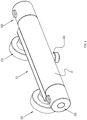
FIG.1 illustrates a schematic diagram of the temperature controllable tap. -
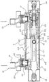
FIG.2 illustrates a sectional diagram of the temperature controllable tap. -
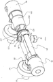
FIG.3 illustrates a sectional diagram of the temperature controllable tap in another view angle. -
FIG.4 illustrates a sectional diagram ofFIG.3 in A-A. -
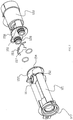
FIG.5 illustrates an exploded and schematic diagram of the temperature controllable tap. -
FIG.6 illustrates a schematic diagram of the first valve base and the second valve base of the temperature controllable tap when they are coupled. -
FIG.7 illustrates a schematic diagram of the first valve base and the second valve base of the temperature controllable tap when they are separated. - Please referring to
FIGs 1∼7 , the temperature controllable tap comprises atap portion 10 with a waterway portion, two joint portions 2 respectively fixedly assembled to and connected to a hot water resource and a cool water resource, anoutlet portion 30, a watertemperature adjusting mechanism 40 and aflow regulating mechanism 50. - The
tap portion 10 comprises ahousing 11 and acore portion 12 of plastic fixedly assembled in thehousing 11, the housing can be made of metal, the waterway portion is entirely disposed in thecore portion 12, thecore portion 12 separates the waterway portion and thehousing 11, so that the water flowing in the waterway portion would not be influenced by the material of the housing, the housing is not needed to be made of copper. Twojoint portions 20 are fixedly connected to thetap portion 10, when assembled, two joint portions 2 are respectively fixedly assembled to and connected to a hot water resource and a cool water resource, so that the waterway portion is connected to the hot water resource and the cool water resource. Theoutlet portion 30 is fixedly connected to thetap portion 10 to connect to the waterway portion. The waterway portion connects the twojoint portions 20 and theoutlet portion 30. The watertemperature adjusting mechanism 40 and theflow regulating mechanism 50 are applied with existing technology, they are respectively assembled to the two ends of thecore portion 12, the watertemperature adjusting mechanism 40 and theflow regulating mechanism 50 are coupled to the waterway portion to respectively achieve flow regulating and temperature adjusting. - Two
joint portions 20 can be referred to existing technology. Thehousing 11 is disposed with twoassembly holes 111 passing through inside and outside, thejoint portion 20 comprises ajoint 21, thejoint 21 passes through theassembly hole 111 to be fixedly assembled to the core portion to connect to the waterway portion. Thejoint portion 20 further comprises anassembly nut 22, thenut 22 is threaded to thejoint 21 at the portion outside the housing, thenut 22 is fixedly connected to the water resource. Preferred, thejoint portion 20 is disposed with anon-return valve 23, afilter screen 24 and aflange cover 25. - The waterway portion comprises a
first waterway 13, amixing waterway 14 and asecond waterway 17, thefirst waterway 13 is connected to onejoint portion 20, themixing waterway 14 is used to connect to thefirst waterway 13, themixing waterway 14 is connected to the otherjoint portion 20 by thesecond waterway 17, the mixing waterway is coupled to the watertemperature adjusting mechanism 40 to adjust the water temperature, theoutlet portion 30 is connected to themixing waterway 14 and theflow regulating mechanism 50 is coupled to the mixingwaterway 14 to control the volume. - Preferred, the
core portion 12 comprises afirst valve base 121 and asecond valve base 122; thefirst waterway 13 has a portion disposed in thefirst valve base 121 and a portion disposed in thesecond valve base 122, themixing waterway 14 has a portion disposed in thefirst valve base 121 and a portion disposed in thesecond valve base 122; thefirst valve base 121 and thesecond valve base 122 are fixedly assembled together to make two portions of thefirst waterway 13 form thefirst waterway 13 and to make two portions of themixing waterway 14 form themixing waterway 14; the watertemperature adjusting mechanism 40 is movably assembled to thesecond valve base 122, theflow regulating mechanism 50 is assembled to thefirst valve base 121. In detailed: - The
first valve base 121 is disposed with afirst water passage 123 and athird water passage 124, thefirst water passage 123 forms the portion of thefirst waterway 13 disposed in thefirst valve base 121, thethird water passage 124 forms the portion of themixing waterway 14 disposed in thefirst valve base 121; the periphery surface of thefirst valve base 121 is concaved with a fourth connecting way connected to the first water passage, thejoint portion 20 is fixedly assembled to the fourth connecting way, so that thefirst water passage 123 is connected to thejoint portion 20. Furthermore, in detailed, thefirst water passage 123 is a blind hole concaved on the coupling end of the first valve base, the blind hole is disposed with the fourth connecting way connected to the periphery surface of thefirst valve base 121; thethird water passage 124 comprises a connecting waterway connected to thefourth water passage 126 and anoutlet passage 127, thefirst water passage 123 is a blind hole concaved at the external end of the first valve base; thefirst water passage 123, the connecting waterway and theoutlet passage 127 are parallel disposed, a third connecting way is disposed between theoutlet passage 127 and the connecting waterway to connect the two, theoutlet portion 30 is connected to the blind end of theoutlet passage 127 to connect to thethird water passage 124, theflow regulating mechanism 50 is assembled to the outlet passage 127and coupled to the third connecting way to control the volume, the volume control comprises on and off. - The
second valve base 122 is disposed with asecond water passage 125 and afourth water passage 126, thesecond water passage 125 forms the portion of themixing waterway 14 disposed at thesecond valve base 122, thefourth water passage 126 forms the portion of themixing waterway 14 disposed at thesecond valve base 122; a first connecting way is disposed between thefourth water passage 126 and thesecond water passage 125 to connect the two water passages, a second connecting way is disposed at thefourth water passage 126 to pass through thesecond valve base 122, the otherjoint portion 20 can be connected to the second connecting way, the second connecting way forms thesecond waterway 17 or a portion of thesecond waterway 17, the second connecting way connects the otherjoint portion 20 and thefourth water passage 126. The watertemperature adjusting mechanism 40 is assembled to thefourth water passage 126 and is coupled to the first connecting way and the second connecting way to adjust the water temperature. in detailed, thesecond water passage 125 is a blind hole concaved at the coupling end of thesecond valve base 122, thefourth water passage 126 passes through thesecond valve base 122, thesecond water passage 125 and thefourth water passage 126 are parallel, the periphery surface of thesecond valve base 122 is concaved with a second connecting way connected to thefourth water passage 126, the first connecting way and the second connecting way are disposed with space along thefourth water passage 126, the watertemperature adjusting mechanism 40 is assembled to thefourth water passage 126 corresponding to the external end of the second valve base to couple to the first connecting way and the second connecting way, the section area of the first connecting way and the second waterway are controlled to adjust the water temperature. - The
first valve base 121 is fixedly assembled to thesecond valve base 122, the coupling end of the first valve base is faced to the coupling end of the second valve base, thefirst water passage 123 is connected to thesecond water passage 125 to form thefirst waterway 13, thethird water passage 124 is connected to thefourth water passage 126 to form themixing waterway 14. - The
first valve base 121 and thesecond valve base 122 are fixedly assembled in this way: - The end of the
first water passage 123 and the end of thethird water passage 124 are connected to the coupling end of thefirst valve base 121, the end of thesecond water passage 125 and the end of thefourth water passage 126 are connected to the coupling end of thesecond valve base 122, the end of thesecond water passage 125 and the end of thefourth water passage 126 are respectively extending outwardly to form aninsert pipe 128, the coupling end of thefirst valve base 121 and the coupling end of thesecond valve base 122 are assembled together, two insert pipes are respectively inserted to the joint passage of thefirst water passage 123 and thethird water passage 124 to achieve connection. The external wall of the insert pipe is concaved with anannular groove 151; the coupling end of thefirst valve base 121 is disposed with aninsert hole 152, the end of thefirst water passage 123 and the end of thethird water passage 124 are respectively extending outwardly to form an insertedpipe 129, the end of the insertedpipe 129, the end of the inserted pipe is disposed with anotch 154 passing through inside and outside, thenotch 154 forms aninsert hole 152 or a portion of theinsert hole 152, the insert pipe is inserted to the inserted pipe to achieve waterway connection, theannular groove 151 and thenotch 154 are aligned; alock element 153 is further configured, two sides of thelock element 153 respectively pass through thenotches 154 of the two inserted pipe and insert to theannular groove 151, thelock element 153 limits the separating of thefirst valve base 121 and thesecond valve base 122, thefirst valve base 121 is detachably connected to thesecond valve base 122 by thelock element 153. - Preferred, the
lock element 153 is disposed with aposition groove 156 symmetrical to aposition element 155, the position groove is coupled to the position element, as needed, the prior two components can be locked to each other for positioning and assembling; the external wall of the end of the inserted pipes of thefirst valve base 121 are connected to form afirst plate 157, the rear side of thefirst plate 157 is aligned with the side surface of the notch, so that the lock element can be inserted from the rear side of thefirst plate 157, it is convenient to assemble; the external wall of the insert pipes of thefirst valve base 121 are connected to form asecond plate 158, when the front surface of the first plate and the front surface of the second plate are face to face to contact with each other, the notch is aligned with the annular groove. As needed, other fixing way are available, for example, the first valve base is fixedly connected to the second valve base by injection molding, the first valve base and the second valve base are once formed that it is convenient for further assembling, other traditional fixing way, such as bolt, lock catch, welding or gluing, are available, it should be noted that they are within the scope of this application. - The
outlet portion 30 is assembled to the first valve base, in detailed, the first valve base is disposed with anassembly hole 16 passing through the first valve base, the assembly hole is connected to the outlet passage, the outlet portion comprises anoutlet pipe 31, theoutlet pipe 31 is assembled to one end of the assembly hole in sealing way, the other end of the assembly hole is disposed with a sealingplug 32, theoutlet pipe 31 is disposed with awater hole 33 connected to an internal hole, theoutlet pipe 31 is threaded to the sealingplug 32, the end of theassembly hole 16 at the rear side is disposed with step surface facing outwardly, the sealingplug 32 is contacted with the step surface, the sealing plug is contacted with the step surface by the threaded connection of the outlet pipe and the sealing plug, so that the outlet pipe, the sealing plug and the first valve base are detachably assembled, the waterway is from the outlet passage, the water hole, to the internal hole of the outlet pipe. - The invention may be summarized as follows: The present invention is provided with a temperature controllable tap, which comprises a tap portion with a waterway portion, two joint portions respectively fixedly assembled to and connected to a hot water resource and a cool water resource, an outlet portion, a water temperature adjusting mechanism and a flow regulating mechanism, two joint portions are fixedly connected to the tap portion, the water temperature adjusting mechanism and the flow regulating mechanism are coupled to the waterway portion to realize flow regulating and water temperature adjusting, the tap portion comprises a housing and a core portion of plastic fixedly assembled in the housing, wherein the waterway portion is entirely disposed in the core portion and the waterway portion connects the two joint portions and the outlet portion, the core portion separates the waterway portion and the housing. The present invention has advantages that the housing is not contacted with the waterway, the material of the housing is not limited; the housing is influenced less by the water temperature, it would not scald the user that it has higher security. Although the present invention has been described with reference to the preferred embodiments thereof for carrying out the patent for invention, it is apparent to those skilled in the art that a variety of modifications and changes may be made without departing from the scope of the patent for invention which is intended to be defined by the appended claims.
Claims (10)
- A temperature controllable tap, comprising a tap portion (10) with a waterway portion, two joint portions (2) respectively fixedly assembled to and connected to a hot water resource and a cool water resource, an outlet portion (30), a water temperature adjusting mechanism (40) and a flow regulating mechanism (50); two joint portions (20) are fixedly connected to the tap portion (10), the water temperature adjusting mechanism (40) and the flow regulating mechanism (50) are coupled to the waterway portion to realize flow regulating and water temperature adjusting, the tap portion (10) comprises a housing (11) and a plastic core portion (12) fixedly assembled in the housing (11), wherein the waterway portion is entirely disposed in the core portion (12) and the waterway portion connects the two joint portions (20) and the outlet portion (30); the core portion (12) separates the waterway portion and the housing (11).
- The temperature controllable tap according to claim 1, wherein the waterway portion comprises a first waterway (13) and a mixing waterway (14), the first waterway (13) is connected to one joint portion (20), the mixing waterway (14) is used to connect the first waterway (13) and the other joint portion (20) and to couple to the water temperature adjusting mechanism (40) to adjust the water temperature, the outlet portion (30) is connected to the mixing waterway (14) and the flow regulating mechanism (50) is coupled to the mixing waterway (14) to control the volume.
- The temperature controllable tap according to claim 1 and/or 2, wherein the water temperature adjusting mechanism (40) and the flow regulating mechanism (50) are respectively assembled to two ends of the core portion (12).
- The temperature controllable tap according to claim 2 and/or 3, wherein the core portion (12) comprises a first valve base (121) and a second valve base (122); the first valve base (121) and the second valve base (122) are fixedly assembled together to form with the first waterway (13) and the mixing waterway (14), the water temperature adjusting mechanism (40) is movably assembled to the second valve base (122), the flow regulating mechanism (50) is assembled to the first valve base (121).
- The temperature controllable tap according to claim 3 and/or 4, wherein:the first waterway (13) comprises a portion disposed in the first valve base (121) and a portion disposed in the second valve base (122), the first valve base (121) and the second valve base (122) are fixedly assembled to make the two portions form the first waterway (13);the mixing waterway (14) comprsies a portion disposed in the first valve base (121) and a portion disposed in the second valve base (122), the first valve base (121) and the second valve base (122) are fixedly assembled to make the two portions form the mixing waterway (14).
- The temperature controllable tap according to claim 4 and/or 5, wherein the first valve base (121) is disposed with a first water passage (123) and a third water passage (124),
the first water passage (123) is connected to one joint portion (20);
the second valve base (122) is disposed with a second water passage (125) and a fourth water passage (126), a first connecting way is disposed between the fourth water passage (126) and
the second water passage (125) to connect the fourth water passage (126) and the second water passage (125), a second connecting way is disposed between the fourth water passage (126) and the other joint portion (20) to connect the fourth water passage (126) and the other joint portion (20); the water temperature adjusting mechanism (40) is assembled to the fourth water passage (126) and coupled to the first connecting way and the second connecting way to adjust the water temperature;
the first water passage (123) is connected to the second water passage (125) to form the first waterway (13), the third water passage (124) is connected to the fourth passage (126) to form the mixing waterway (14);
the flow regulating mechanism (50) is coupled to the third water passage (124) to control the volume, the outlet portion (30) is connected to the third water passage (124). - The temperature controllable tap according to claim 5 and/or 6, wherein the portion of the mixing waterway (14) disposed in the first valve base (121) comprises a connecting waterway connected to the fourth water passage (126) and an outlet passage (127), a third connecting way is disposed between the outlet passage (127) and the connecting waterway to connect the outlet passage (127) and the connecting waterway, the outlet portion (30) is connected to the outlet passage (127), the flow regulating mechanism (50) is assembled to the outlet passage (127) to couple to the third connecting way to control the volume.
- The temperature controllable tap according to claim 6 and/or 7, wherein the end of
the first water passage (123) and the end of the third water passage (124) are connected to a coupling end of the first valve base (121), the end of the second water passage (125) and the end of the fourth water passage (126) are connected to a coupling end of the second valve base (122), the coupling end of the first valve base (121) and the coupling end of the second valve base (122) are assembled together, the end of the first water passage (123) and the end of the third water passage (124), the end of the second water passage (125) and the end of the fourth water passage (126) are respectively connected in inserting way. - The temperature controllable tap according to claim 8, wherein:
the end of the second water passage (125) and the end of the fourth water passage (126) of the second valve base (122) are respectively extending outwardly to form an insert pipe; two insert pipes are respectively inserted to the first water passage (123) and the third water passage (124) to realize connection;
the outer wall of the insert pipe is concaved with an annular groove (151); the coupling end of the first valve base (121) is disposed with an insert hole (152), a lock element (153) is further provided to insert to the insert hole (152) that two sides of the lock element (153) are respectively locked to the annular grooves (151) of the two insert pipes, the first valve base (121) is detachably connected to the second valve base (122) by the lock element (153). - The temperature controllable tap according to claim 9, wherein the end of the first water passage (123) and the end of the third water passage (124) are respectively extending outwardly to form an inserted pipe, the end of the insert pipe is disposed with a notch (154) passing through inside and outside, the notch (154) forms the insert hole (152) or a portion of the insert hole (152), the insert pipe is inserted to the inserted pipe, the annular groove (151) is aligned with the notch (154), two sides of the lock element (153) respectively pass through the notches (154) of the two inserted pipes and insert to the annular grooves (151), the first valve base (121) and the second valve base (122) are limited to separate by the lock element (153).
Applications Claiming Priority (1)
| Application Number | Priority Date | Filing Date | Title |
|---|---|---|---|
| CN201610157162.5A CN107218408B (en) | 2016-03-18 | 2016-03-18 | temperature control faucet |
Publications (2)
| Publication Number | Publication Date |
|---|---|
| EP3219858A1 true EP3219858A1 (en) | 2017-09-20 |
| EP3219858B1 EP3219858B1 (en) | 2023-05-24 |
Family
ID=57681187
Family Applications (1)
| Application Number | Title | Priority Date | Filing Date |
|---|---|---|---|
| EP16002646.4A Active EP3219858B1 (en) | 2016-03-18 | 2016-12-13 | A temperature controlling tap |
Country Status (2)
| Country | Link |
|---|---|
| EP (1) | EP3219858B1 (en) |
| CN (1) | CN107218408B (en) |
Cited By (8)
| Publication number | Priority date | Publication date | Assignee | Title |
|---|---|---|---|---|
| CN107575607A (en) * | 2017-09-30 | 2018-01-12 | 宁波慈立恒温科技有限公司 | A kind of stable constant-temperature tap of output water temperature |
| FR3072751A1 (en) * | 2017-10-24 | 2019-04-26 | Vernet | MIXER AND METHOD FOR INTERVERSION OF SUCH A MIXER |
| FR3072752A1 (en) * | 2017-10-24 | 2019-04-26 | Vernet | INTERNAL ASSEMBLY FOR A MIXER |
| DE102019003193A1 (en) * | 2019-05-07 | 2020-11-12 | Grohe Ag | Thermostatic cartridge for a sanitary fitting |
| GB2590143A (en) * | 2019-09-26 | 2021-06-23 | Ppi Xiamen Ind Co Ltd | Split-type thermostatic faucet main body and split-type thermostatic faucet |
| DE102020107262A1 (en) | 2020-03-17 | 2021-09-23 | Grohe Ag | Sanitary fitting with plastic inner part |
| EP3929364A1 (en) * | 2020-06-26 | 2021-12-29 | Grohe AG | Thermostatic mixing valve and method for its production |
| CN115403085A (en) * | 2022-02-28 | 2022-11-29 | 青岛经济技术开发区海尔热水器有限公司 | Water treatment device |
Families Citing this family (3)
| Publication number | Priority date | Publication date | Assignee | Title |
|---|---|---|---|---|
| CN109654289B (en) * | 2017-10-12 | 2024-10-15 | 厦门松霖科技股份有限公司 | Low pressure large flow shower |
| CN108930820A (en) * | 2018-08-28 | 2018-12-04 | 宁波敏宝卫浴五金水暖洁具有限公司 | A kind of cold touching constant-temperature tap |
| CN113639123B (en) * | 2020-04-27 | 2025-05-06 | 厦门松霖科技股份有限公司 | Pipe-in-pipe joint fixing device |
Citations (4)
| Publication number | Priority date | Publication date | Assignee | Title |
|---|---|---|---|---|
| EP0647808A1 (en) * | 1993-04-23 | 1995-04-12 | Toto Ltd. | Mixing faucet |
| EP2182122A1 (en) * | 2008-11-04 | 2010-05-05 | Kludi GmbH & Co. KG | Surface mounted shower mixer |
| EP2388676A2 (en) * | 2010-04-23 | 2011-11-23 | Suprema (Zhuhai J/V) Thermostatic Sanitaryware Co., Ltd | Anti-scald thermostatic water tap |
| US20130241196A1 (en) * | 2012-03-16 | 2013-09-19 | Hansgrohe Se | Fitting main body for a sanitary fitting |
Family Cites Families (17)
| Publication number | Priority date | Publication date | Assignee | Title |
|---|---|---|---|---|
| JP3310546B2 (en) * | 1996-06-01 | 2002-08-05 | 株式会社三栄水栓製作所 | Hot water mixer tap |
| US5875808A (en) * | 1997-12-11 | 1999-03-02 | Tai Yi Tong Industrial Co., Ltd. | Burnproof device of triple/double switch combination faucet |
| CN201802927U (en) * | 2010-03-30 | 2011-04-20 | 珠海市舒丽玛温控卫浴设备有限公司 | Thermostatic faucet with novel main structure |
| CN201916542U (en) * | 2010-08-18 | 2011-08-03 | 珠海市舒丽玛温控卫浴设备有限公司 | Vertical reversing thermostatic faucet |
| CN202074076U (en) * | 2011-06-03 | 2011-12-14 | 山东悦悦温控卫浴设备有限公司 | Multifunctional temperature-controlled tap |
| CN202402708U (en) * | 2011-12-01 | 2012-08-29 | 厦门市易洁卫浴有限公司 | Anti-scald temperature control faucet |
| CN203115189U (en) * | 2013-01-04 | 2013-08-07 | 路达(厦门)工业有限公司 | Constant-temperature faucet structure |
| ITMI20130584A1 (en) * | 2013-04-11 | 2014-10-12 | Carlo Nobili S P A Rubinetterie | EXTERNAL THERMOSTATIC MIXER, PARTICULARLY FOR HYGIENIC-SANITARY COMPONENTS, HIGHLY SAFE AGAINST THE DANGER OF BURNS FROM CONTACT. |
| CN203363328U (en) * | 2013-06-08 | 2013-12-25 | 本科电器有限公司 | Surface anti-scalding constant temperature faucet shell and faucet thereof |
| CN203363288U (en) * | 2013-06-25 | 2013-12-25 | 鹏威(厦门)工业有限公司 | Cold touch type constant-temperature faucet |
| CN203421217U (en) * | 2013-07-30 | 2014-02-05 | 鹏威(厦门)工业有限公司 | Two-outlet constant-temperature faucet structure |
| CN204099709U (en) * | 2014-09-11 | 2015-01-14 | 宁波新慈立洁具有限公司 | A kind of Novel constant-temperature faucet |
| CN204176028U (en) * | 2014-10-29 | 2015-02-25 | 宁波新慈立洁具有限公司 | A kind of Novel constant-temperature faucet |
| CN204459293U (en) * | 2014-12-08 | 2015-07-08 | 刘兆祥 | A kind of anti-scald constant-temperature tap |
| CN204677823U (en) * | 2015-05-23 | 2015-09-30 | 宁波慈立恒温科技有限公司 | A kind of constant-temperature tap |
| CN205001598U (en) * | 2015-08-28 | 2016-01-27 | 台州市国人温控卫浴设备有限公司 | Prevent constant temperature faucet that scalds |
| CN205859221U (en) * | 2016-03-18 | 2017-01-04 | 厦门松霖科技有限公司 | A kind of temperature control tap |
-
2016
- 2016-03-18 CN CN201610157162.5A patent/CN107218408B/en active Active
- 2016-12-13 EP EP16002646.4A patent/EP3219858B1/en active Active
Patent Citations (4)
| Publication number | Priority date | Publication date | Assignee | Title |
|---|---|---|---|---|
| EP0647808A1 (en) * | 1993-04-23 | 1995-04-12 | Toto Ltd. | Mixing faucet |
| EP2182122A1 (en) * | 2008-11-04 | 2010-05-05 | Kludi GmbH & Co. KG | Surface mounted shower mixer |
| EP2388676A2 (en) * | 2010-04-23 | 2011-11-23 | Suprema (Zhuhai J/V) Thermostatic Sanitaryware Co., Ltd | Anti-scald thermostatic water tap |
| US20130241196A1 (en) * | 2012-03-16 | 2013-09-19 | Hansgrohe Se | Fitting main body for a sanitary fitting |
Cited By (15)
| Publication number | Priority date | Publication date | Assignee | Title |
|---|---|---|---|---|
| CN107575607A (en) * | 2017-09-30 | 2018-01-12 | 宁波慈立恒温科技有限公司 | A kind of stable constant-temperature tap of output water temperature |
| CN107575607B (en) * | 2017-09-30 | 2024-03-19 | 宁波慈立恒温科技有限公司 | Constant temperature tap with stable water temperature of water outlet |
| GB2581612B (en) * | 2017-10-24 | 2022-05-25 | Vernet | Mixer and method for interverting such a mixer |
| FR3072751A1 (en) * | 2017-10-24 | 2019-04-26 | Vernet | MIXER AND METHOD FOR INTERVERSION OF SUCH A MIXER |
| FR3072752A1 (en) * | 2017-10-24 | 2019-04-26 | Vernet | INTERNAL ASSEMBLY FOR A MIXER |
| WO2019081505A1 (en) * | 2017-10-24 | 2019-05-02 | Vernet | Internal assembly for a mixer |
| WO2019081500A1 (en) * | 2017-10-24 | 2019-05-02 | Vernet | MIXER AND METHOD FOR INTERVERSION OF SUCH A MIXER |
| GB2581612A (en) * | 2017-10-24 | 2020-08-26 | Vernet | Mixer and method for interverting such a mixer |
| DE102019003193A1 (en) * | 2019-05-07 | 2020-11-12 | Grohe Ag | Thermostatic cartridge for a sanitary fitting |
| GB2590143B (en) * | 2019-09-26 | 2022-01-12 | Ppi Xiamen Ind Co Ltd | Split-type thermostatic faucet main body and split-type thermostatic faucet |
| GB2590143A (en) * | 2019-09-26 | 2021-06-23 | Ppi Xiamen Ind Co Ltd | Split-type thermostatic faucet main body and split-type thermostatic faucet |
| DE102020107262A1 (en) | 2020-03-17 | 2021-09-23 | Grohe Ag | Sanitary fitting with plastic inner part |
| EP3929364A1 (en) * | 2020-06-26 | 2021-12-29 | Grohe AG | Thermostatic mixing valve and method for its production |
| CN115403085A (en) * | 2022-02-28 | 2022-11-29 | 青岛经济技术开发区海尔热水器有限公司 | Water treatment device |
| CN115403085B (en) * | 2022-02-28 | 2023-07-18 | 青岛经济技术开发区海尔热水器有限公司 | water treatment device |
Also Published As
| Publication number | Publication date |
|---|---|
| EP3219858B1 (en) | 2023-05-24 |
| CN107218408B (en) | 2020-08-11 |
| CN107218408A (en) | 2017-09-29 |
Similar Documents
| Publication | Publication Date | Title |
|---|---|---|
| EP3219858B1 (en) | A temperature controlling tap | |
| US7384007B2 (en) | Shower head structure | |
| CN105546157A (en) | Fluid mixing valve | |
| CN110594469B (en) | A split thermostatic faucet body and a split thermostatic faucet | |
| US20170328042A1 (en) | Wall faucet | |
| CN110966445A (en) | Valve assembly, electrically operated valve and thermal management assembly | |
| CN204164453U (en) | Electric expansion valve | |
| JP2012172772A (en) | Mixing faucet | |
| CN205298661U (en) | Fluid mixing valve | |
| CN104089053B (en) | Water tap assembly and manufacturing method for water tap assembly | |
| CN106051265B (en) | Valves and Valve Assemblies | |
| CN108369426B (en) | Thermostatic spool for controlling hot and cold fluids to be mixed | |
| US9016302B2 (en) | Cold/hot water balance valve with burn-proof functions | |
| CN110966414A (en) | Electric valves and thermal management components | |
| US20130087232A1 (en) | Balance valve having an asymmetric structure | |
| EP3214350A2 (en) | Thermostatic tap for liquid fluids | |
| CN217030062U (en) | Double-handle water tap | |
| CN205859221U (en) | A kind of temperature control tap | |
| CN215334691U (en) | a restrictor valve | |
| CN204239809U (en) | Faucet assembly | |
| CN215334645U (en) | Shower set | |
| CN210674818U (en) | End caps, filter elements and water purification equipment | |
| CN112483697A (en) | Flow limiting valve | |
| CN215371095U (en) | Bathtub faucet | |
| CN104949326A (en) | Heater arrangement |
Legal Events
| Date | Code | Title | Description |
|---|---|---|---|
| PUAI | Public reference made under article 153(3) epc to a published international application that has entered the european phase |
Free format text: ORIGINAL CODE: 0009012 |
|
| STAA | Information on the status of an ep patent application or granted ep patent |
Free format text: STATUS: THE APPLICATION HAS BEEN PUBLISHED |
|
| AK | Designated contracting states |
Kind code of ref document: A1 Designated state(s): AL AT BE BG CH CY CZ DE DK EE ES FI FR GB GR HR HU IE IS IT LI LT LU LV MC MK MT NL NO PL PT RO RS SE SI SK SM TR |
|
| AX | Request for extension of the european patent |
Extension state: BA ME |
|
| RAP1 | Party data changed (applicant data changed or rights of an application transferred) |
Owner name: XIAMEN SOLEX HIGH-TECH INDUSTRIES CO., LTD. |
|
| STAA | Information on the status of an ep patent application or granted ep patent |
Free format text: STATUS: REQUEST FOR EXAMINATION WAS MADE |
|
| RAP1 | Party data changed (applicant data changed or rights of an application transferred) |
Owner name: XIAMEN SOLEX HIGH-TECH INDUSTRIES CO., LTD. |
|
| 17P | Request for examination filed |
Effective date: 20180312 |
|
| RBV | Designated contracting states (corrected) |
Designated state(s): AL AT BE BG CH CY CZ DE DK EE ES FI FR GB GR HR HU IE IS IT LI LT LU LV MC MK MT NL NO PL PT RO RS SE SI SK SM TR |
|
| STAA | Information on the status of an ep patent application or granted ep patent |
Free format text: STATUS: EXAMINATION IS IN PROGRESS |
|
| 17Q | First examination report despatched |
Effective date: 20190718 |
|
| REG | Reference to a national code |
Ref country code: DE Ref legal event code: R079 Ref document number: 602016079532 Country of ref document: DE Free format text: PREVIOUS MAIN CLASS: E03C0001040000 Ipc: E03C0001042000 |
|
| GRAP | Despatch of communication of intention to grant a patent |
Free format text: ORIGINAL CODE: EPIDOSNIGR1 |
|
| STAA | Information on the status of an ep patent application or granted ep patent |
Free format text: STATUS: GRANT OF PATENT IS INTENDED |
|
| RIC1 | Information provided on ipc code assigned before grant |
Ipc: E03C 1/04 20060101ALI20221104BHEP Ipc: E03C 1/042 20060101AFI20221104BHEP |
|
| INTG | Intention to grant announced |
Effective date: 20221207 |
|
| RIN1 | Information on inventor provided before grant (corrected) |
Inventor name: WU, YUZHI Inventor name: RUAN, XIAOFENG Inventor name: HUANG, CHANGZHI |
|
| GRAS | Grant fee paid |
Free format text: ORIGINAL CODE: EPIDOSNIGR3 |
|
| GRAA | (expected) grant |
Free format text: ORIGINAL CODE: 0009210 |
|
| STAA | Information on the status of an ep patent application or granted ep patent |
Free format text: STATUS: THE PATENT HAS BEEN GRANTED |
|
| AK | Designated contracting states |
Kind code of ref document: B1 Designated state(s): AL AT BE BG CH CY CZ DE DK EE ES FI FR GB GR HR HU IE IS IT LI LT LU LV MC MK MT NL NO PL PT RO RS SE SI SK SM TR |
|
| REG | Reference to a national code |
Ref country code: GB Ref legal event code: FG4D |
|
| REG | Reference to a national code |
Ref country code: CH Ref legal event code: EP |
|
| REG | Reference to a national code |
Ref country code: DE Ref legal event code: R096 Ref document number: 602016079532 Country of ref document: DE |
|
| REG | Reference to a national code |
Ref country code: AT Ref legal event code: REF Ref document number: 1569554 Country of ref document: AT Kind code of ref document: T Effective date: 20230615 |
|
| REG | Reference to a national code |
Ref country code: IE Ref legal event code: FG4D |
|
| REG | Reference to a national code |
Ref country code: LT Ref legal event code: MG9D |
|
| REG | Reference to a national code |
Ref country code: NL Ref legal event code: MP Effective date: 20230524 |
|
| REG | Reference to a national code |
Ref country code: AT Ref legal event code: MK05 Ref document number: 1569554 Country of ref document: AT Kind code of ref document: T Effective date: 20230524 |
|
| PG25 | Lapsed in a contracting state [announced via postgrant information from national office to epo] |
Ref country code: SE Free format text: LAPSE BECAUSE OF FAILURE TO SUBMIT A TRANSLATION OF THE DESCRIPTION OR TO PAY THE FEE WITHIN THE PRESCRIBED TIME-LIMIT Effective date: 20230524 Ref country code: PT Free format text: LAPSE BECAUSE OF FAILURE TO SUBMIT A TRANSLATION OF THE DESCRIPTION OR TO PAY THE FEE WITHIN THE PRESCRIBED TIME-LIMIT Effective date: 20230925 Ref country code: NO Free format text: LAPSE BECAUSE OF FAILURE TO SUBMIT A TRANSLATION OF THE DESCRIPTION OR TO PAY THE FEE WITHIN THE PRESCRIBED TIME-LIMIT Effective date: 20230824 Ref country code: NL Free format text: LAPSE BECAUSE OF FAILURE TO SUBMIT A TRANSLATION OF THE DESCRIPTION OR TO PAY THE FEE WITHIN THE PRESCRIBED TIME-LIMIT Effective date: 20230524 Ref country code: ES Free format text: LAPSE BECAUSE OF FAILURE TO SUBMIT A TRANSLATION OF THE DESCRIPTION OR TO PAY THE FEE WITHIN THE PRESCRIBED TIME-LIMIT Effective date: 20230524 Ref country code: AT Free format text: LAPSE BECAUSE OF FAILURE TO SUBMIT A TRANSLATION OF THE DESCRIPTION OR TO PAY THE FEE WITHIN THE PRESCRIBED TIME-LIMIT Effective date: 20230524 |
|
| PG25 | Lapsed in a contracting state [announced via postgrant information from national office to epo] |
Ref country code: RS Free format text: LAPSE BECAUSE OF FAILURE TO SUBMIT A TRANSLATION OF THE DESCRIPTION OR TO PAY THE FEE WITHIN THE PRESCRIBED TIME-LIMIT Effective date: 20230524 Ref country code: PL Free format text: LAPSE BECAUSE OF FAILURE TO SUBMIT A TRANSLATION OF THE DESCRIPTION OR TO PAY THE FEE WITHIN THE PRESCRIBED TIME-LIMIT Effective date: 20230524 Ref country code: LV Free format text: LAPSE BECAUSE OF FAILURE TO SUBMIT A TRANSLATION OF THE DESCRIPTION OR TO PAY THE FEE WITHIN THE PRESCRIBED TIME-LIMIT Effective date: 20230524 Ref country code: LT Free format text: LAPSE BECAUSE OF FAILURE TO SUBMIT A TRANSLATION OF THE DESCRIPTION OR TO PAY THE FEE WITHIN THE PRESCRIBED TIME-LIMIT Effective date: 20230524 Ref country code: IS Free format text: LAPSE BECAUSE OF FAILURE TO SUBMIT A TRANSLATION OF THE DESCRIPTION OR TO PAY THE FEE WITHIN THE PRESCRIBED TIME-LIMIT Effective date: 20230924 Ref country code: HR Free format text: LAPSE BECAUSE OF FAILURE TO SUBMIT A TRANSLATION OF THE DESCRIPTION OR TO PAY THE FEE WITHIN THE PRESCRIBED TIME-LIMIT Effective date: 20230524 Ref country code: GR Free format text: LAPSE BECAUSE OF FAILURE TO SUBMIT A TRANSLATION OF THE DESCRIPTION OR TO PAY THE FEE WITHIN THE PRESCRIBED TIME-LIMIT Effective date: 20230825 |
|
| PG25 | Lapsed in a contracting state [announced via postgrant information from national office to epo] |
Ref country code: FI Free format text: LAPSE BECAUSE OF FAILURE TO SUBMIT A TRANSLATION OF THE DESCRIPTION OR TO PAY THE FEE WITHIN THE PRESCRIBED TIME-LIMIT Effective date: 20230524 |
|
| PG25 | Lapsed in a contracting state [announced via postgrant information from national office to epo] |
Ref country code: SK Free format text: LAPSE BECAUSE OF FAILURE TO SUBMIT A TRANSLATION OF THE DESCRIPTION OR TO PAY THE FEE WITHIN THE PRESCRIBED TIME-LIMIT Effective date: 20230524 |
|
| PG25 | Lapsed in a contracting state [announced via postgrant information from national office to epo] |
Ref country code: SM Free format text: LAPSE BECAUSE OF FAILURE TO SUBMIT A TRANSLATION OF THE DESCRIPTION OR TO PAY THE FEE WITHIN THE PRESCRIBED TIME-LIMIT Effective date: 20230524 Ref country code: SK Free format text: LAPSE BECAUSE OF FAILURE TO SUBMIT A TRANSLATION OF THE DESCRIPTION OR TO PAY THE FEE WITHIN THE PRESCRIBED TIME-LIMIT Effective date: 20230524 Ref country code: RO Free format text: LAPSE BECAUSE OF FAILURE TO SUBMIT A TRANSLATION OF THE DESCRIPTION OR TO PAY THE FEE WITHIN THE PRESCRIBED TIME-LIMIT Effective date: 20230524 Ref country code: EE Free format text: LAPSE BECAUSE OF FAILURE TO SUBMIT A TRANSLATION OF THE DESCRIPTION OR TO PAY THE FEE WITHIN THE PRESCRIBED TIME-LIMIT Effective date: 20230524 Ref country code: DK Free format text: LAPSE BECAUSE OF FAILURE TO SUBMIT A TRANSLATION OF THE DESCRIPTION OR TO PAY THE FEE WITHIN THE PRESCRIBED TIME-LIMIT Effective date: 20230524 Ref country code: CZ Free format text: LAPSE BECAUSE OF FAILURE TO SUBMIT A TRANSLATION OF THE DESCRIPTION OR TO PAY THE FEE WITHIN THE PRESCRIBED TIME-LIMIT Effective date: 20230524 |
|
| REG | Reference to a national code |
Ref country code: DE Ref legal event code: R097 Ref document number: 602016079532 Country of ref document: DE |
|
| PLBE | No opposition filed within time limit |
Free format text: ORIGINAL CODE: 0009261 |
|
| STAA | Information on the status of an ep patent application or granted ep patent |
Free format text: STATUS: NO OPPOSITION FILED WITHIN TIME LIMIT |
|
| 26N | No opposition filed |
Effective date: 20240227 |
|
| PG25 | Lapsed in a contracting state [announced via postgrant information from national office to epo] |
Ref country code: SI Free format text: LAPSE BECAUSE OF FAILURE TO SUBMIT A TRANSLATION OF THE DESCRIPTION OR TO PAY THE FEE WITHIN THE PRESCRIBED TIME-LIMIT Effective date: 20230524 |
|
| PG25 | Lapsed in a contracting state [announced via postgrant information from national office to epo] |
Ref country code: SI Free format text: LAPSE BECAUSE OF FAILURE TO SUBMIT A TRANSLATION OF THE DESCRIPTION OR TO PAY THE FEE WITHIN THE PRESCRIBED TIME-LIMIT Effective date: 20230524 Ref country code: IT Free format text: LAPSE BECAUSE OF FAILURE TO SUBMIT A TRANSLATION OF THE DESCRIPTION OR TO PAY THE FEE WITHIN THE PRESCRIBED TIME-LIMIT Effective date: 20230524 |
|
| REG | Reference to a national code |
Ref country code: DE Ref legal event code: R119 Ref document number: 602016079532 Country of ref document: DE |
|
| REG | Reference to a national code |
Ref country code: CH Ref legal event code: PL |
|
| PG25 | Lapsed in a contracting state [announced via postgrant information from national office to epo] |
Ref country code: LU Free format text: LAPSE BECAUSE OF NON-PAYMENT OF DUE FEES Effective date: 20231213 |
|
| PG25 | Lapsed in a contracting state [announced via postgrant information from national office to epo] |
Ref country code: MC Free format text: LAPSE BECAUSE OF FAILURE TO SUBMIT A TRANSLATION OF THE DESCRIPTION OR TO PAY THE FEE WITHIN THE PRESCRIBED TIME-LIMIT Effective date: 20230524 |
|
| REG | Reference to a national code |
Ref country code: BE Ref legal event code: MM Effective date: 20231231 |
|
| PG25 | Lapsed in a contracting state [announced via postgrant information from national office to epo] |
Ref country code: MC Free format text: LAPSE BECAUSE OF FAILURE TO SUBMIT A TRANSLATION OF THE DESCRIPTION OR TO PAY THE FEE WITHIN THE PRESCRIBED TIME-LIMIT Effective date: 20230524 Ref country code: LU Free format text: LAPSE BECAUSE OF NON-PAYMENT OF DUE FEES Effective date: 20231213 |
|
| REG | Reference to a national code |
Ref country code: IE Ref legal event code: MM4A |
|
| PG25 | Lapsed in a contracting state [announced via postgrant information from national office to epo] |
Ref country code: DE Free format text: LAPSE BECAUSE OF NON-PAYMENT OF DUE FEES Effective date: 20240702 Ref country code: IE Free format text: LAPSE BECAUSE OF NON-PAYMENT OF DUE FEES Effective date: 20231213 |
|
| PG25 | Lapsed in a contracting state [announced via postgrant information from national office to epo] |
Ref country code: BE Free format text: LAPSE BECAUSE OF NON-PAYMENT OF DUE FEES Effective date: 20231231 |
|
| PG25 | Lapsed in a contracting state [announced via postgrant information from national office to epo] |
Ref country code: CH Free format text: LAPSE BECAUSE OF NON-PAYMENT OF DUE FEES Effective date: 20231231 |
|
| PG25 | Lapsed in a contracting state [announced via postgrant information from national office to epo] |
Ref country code: IE Free format text: LAPSE BECAUSE OF NON-PAYMENT OF DUE FEES Effective date: 20231213 Ref country code: DE Free format text: LAPSE BECAUSE OF NON-PAYMENT OF DUE FEES Effective date: 20240702 Ref country code: CH Free format text: LAPSE BECAUSE OF NON-PAYMENT OF DUE FEES Effective date: 20231231 Ref country code: BE Free format text: LAPSE BECAUSE OF NON-PAYMENT OF DUE FEES Effective date: 20231231 |
|
| PG25 | Lapsed in a contracting state [announced via postgrant information from national office to epo] |
Ref country code: BG Free format text: LAPSE BECAUSE OF FAILURE TO SUBMIT A TRANSLATION OF THE DESCRIPTION OR TO PAY THE FEE WITHIN THE PRESCRIBED TIME-LIMIT Effective date: 20230524 |
|
| PG25 | Lapsed in a contracting state [announced via postgrant information from national office to epo] |
Ref country code: BG Free format text: LAPSE BECAUSE OF FAILURE TO SUBMIT A TRANSLATION OF THE DESCRIPTION OR TO PAY THE FEE WITHIN THE PRESCRIBED TIME-LIMIT Effective date: 20230524 |
|
| PG25 | Lapsed in a contracting state [announced via postgrant information from national office to epo] |
Ref country code: CY Free format text: LAPSE BECAUSE OF FAILURE TO SUBMIT A TRANSLATION OF THE DESCRIPTION OR TO PAY THE FEE WITHIN THE PRESCRIBED TIME-LIMIT; INVALID AB INITIO Effective date: 20161213 |
|
| PG25 | Lapsed in a contracting state [announced via postgrant information from national office to epo] |
Ref country code: HU Free format text: LAPSE BECAUSE OF FAILURE TO SUBMIT A TRANSLATION OF THE DESCRIPTION OR TO PAY THE FEE WITHIN THE PRESCRIBED TIME-LIMIT; INVALID AB INITIO Effective date: 20161213 |
|
| PG25 | Lapsed in a contracting state [announced via postgrant information from national office to epo] |
Ref country code: TR Free format text: LAPSE BECAUSE OF FAILURE TO SUBMIT A TRANSLATION OF THE DESCRIPTION OR TO PAY THE FEE WITHIN THE PRESCRIBED TIME-LIMIT Effective date: 20230524 |
|
| PGFP | Annual fee paid to national office [announced via postgrant information from national office to epo] |
Ref country code: GB Payment date: 20251219 Year of fee payment: 10 |
|
| PGFP | Annual fee paid to national office [announced via postgrant information from national office to epo] |
Ref country code: FR Payment date: 20251223 Year of fee payment: 10 |