EP3219624A1 - Taxi tug with auxiliary power services - Google Patents
Taxi tug with auxiliary power services Download PDFInfo
- Publication number
- EP3219624A1 EP3219624A1 EP17161872.1A EP17161872A EP3219624A1 EP 3219624 A1 EP3219624 A1 EP 3219624A1 EP 17161872 A EP17161872 A EP 17161872A EP 3219624 A1 EP3219624 A1 EP 3219624A1
- Authority
- EP
- European Patent Office
- Prior art keywords
- taxi
- tug
- aircraft
- chassis
- disposed
- Prior art date
- Legal status (The legal status is an assumption and is not a legal conclusion. Google has not performed a legal analysis and makes no representation as to the accuracy of the status listed.)
- Granted
Links
- 230000001143 conditioned effect Effects 0.000 claims abstract description 5
- 230000007613 environmental effect Effects 0.000 claims description 5
- 239000003570 air Substances 0.000 description 16
- 238000004891 communication Methods 0.000 description 12
- 239000000446 fuel Substances 0.000 description 8
- 238000012546 transfer Methods 0.000 description 7
- 238000012544 monitoring process Methods 0.000 description 4
- 230000007423 decrease Effects 0.000 description 3
- 230000005611 electricity Effects 0.000 description 3
- 238000004146 energy storage Methods 0.000 description 3
- 239000012080 ambient air Substances 0.000 description 2
- 230000008901 benefit Effects 0.000 description 2
- 238000002485 combustion reaction Methods 0.000 description 2
- 230000008878 coupling Effects 0.000 description 2
- 238000010168 coupling process Methods 0.000 description 2
- 238000005859 coupling reaction Methods 0.000 description 2
- 230000003287 optical effect Effects 0.000 description 2
- UGFAIRIUMAVXCW-UHFFFAOYSA-N Carbon monoxide Chemical compound [O+]#[C-] UGFAIRIUMAVXCW-UHFFFAOYSA-N 0.000 description 1
- 230000004075 alteration Effects 0.000 description 1
- 230000003466 anti-cipated effect Effects 0.000 description 1
- 229910002091 carbon monoxide Inorganic materials 0.000 description 1
- 238000001816 cooling Methods 0.000 description 1
- 239000003344 environmental pollutant Substances 0.000 description 1
- 230000037406 food intake Effects 0.000 description 1
- 230000036541 health Effects 0.000 description 1
- 238000010438 heat treatment Methods 0.000 description 1
- 229930195733 hydrocarbon Natural products 0.000 description 1
- 150000002430 hydrocarbons Chemical class 0.000 description 1
- 230000005764 inhibitory process Effects 0.000 description 1
- 238000012423 maintenance Methods 0.000 description 1
- 239000012528 membrane Substances 0.000 description 1
- 238000000034 method Methods 0.000 description 1
- 231100000719 pollutant Toxicity 0.000 description 1
- 229920000642 polymer Polymers 0.000 description 1
- 238000000926 separation method Methods 0.000 description 1
- 239000007787 solid Substances 0.000 description 1
- 239000007858 starting material Substances 0.000 description 1
- 238000006467 substitution reaction Methods 0.000 description 1
- 238000010977 unit operation Methods 0.000 description 1
Images
Classifications
-
- B—PERFORMING OPERATIONS; TRANSPORTING
- B64—AIRCRAFT; AVIATION; COSMONAUTICS
- B64F—GROUND OR AIRCRAFT-CARRIER-DECK INSTALLATIONS SPECIALLY ADAPTED FOR USE IN CONNECTION WITH AIRCRAFT; DESIGNING, MANUFACTURING, ASSEMBLING, CLEANING, MAINTAINING OR REPAIRING AIRCRAFT, NOT OTHERWISE PROVIDED FOR; HANDLING, TRANSPORTING, TESTING OR INSPECTING AIRCRAFT COMPONENTS, NOT OTHERWISE PROVIDED FOR
- B64F1/00—Ground or aircraft-carrier-deck installations
- B64F1/22—Ground or aircraft-carrier-deck installations installed for handling aircraft
- B64F1/225—Towing trucks
- B64F1/228—Towing trucks remotely controlled, or autonomously operated
-
- B—PERFORMING OPERATIONS; TRANSPORTING
- B64—AIRCRAFT; AVIATION; COSMONAUTICS
- B64F—GROUND OR AIRCRAFT-CARRIER-DECK INSTALLATIONS SPECIALLY ADAPTED FOR USE IN CONNECTION WITH AIRCRAFT; DESIGNING, MANUFACTURING, ASSEMBLING, CLEANING, MAINTAINING OR REPAIRING AIRCRAFT, NOT OTHERWISE PROVIDED FOR; HANDLING, TRANSPORTING, TESTING OR INSPECTING AIRCRAFT COMPONENTS, NOT OTHERWISE PROVIDED FOR
- B64F1/00—Ground or aircraft-carrier-deck installations
- B64F1/34—Ground or aircraft-carrier-deck installations for starting propulsion plant
-
- B64F1/352—
-
- B—PERFORMING OPERATIONS; TRANSPORTING
- B64—AIRCRAFT; AVIATION; COSMONAUTICS
- B64F—GROUND OR AIRCRAFT-CARRIER-DECK INSTALLATIONS SPECIALLY ADAPTED FOR USE IN CONNECTION WITH AIRCRAFT; DESIGNING, MANUFACTURING, ASSEMBLING, CLEANING, MAINTAINING OR REPAIRING AIRCRAFT, NOT OTHERWISE PROVIDED FOR; HANDLING, TRANSPORTING, TESTING OR INSPECTING AIRCRAFT COMPONENTS, NOT OTHERWISE PROVIDED FOR
- B64F1/00—Ground or aircraft-carrier-deck installations
- B64F1/36—Other airport installations
- B64F1/362—Installations for supplying conditioned air to parked aircraft
- B64F1/364—Mobile units
-
- B—PERFORMING OPERATIONS; TRANSPORTING
- B64—AIRCRAFT; AVIATION; COSMONAUTICS
- B64D—EQUIPMENT FOR FITTING IN OR TO AIRCRAFT; FLIGHT SUITS; PARACHUTES; ARRANGEMENTS OR MOUNTING OF POWER PLANTS OR PROPULSION TRANSMISSIONS IN AIRCRAFT
- B64D2221/00—Electric power distribution systems onboard aircraft
-
- B—PERFORMING OPERATIONS; TRANSPORTING
- B64—AIRCRAFT; AVIATION; COSMONAUTICS
- B64F—GROUND OR AIRCRAFT-CARRIER-DECK INSTALLATIONS SPECIALLY ADAPTED FOR USE IN CONNECTION WITH AIRCRAFT; DESIGNING, MANUFACTURING, ASSEMBLING, CLEANING, MAINTAINING OR REPAIRING AIRCRAFT, NOT OTHERWISE PROVIDED FOR; HANDLING, TRANSPORTING, TESTING OR INSPECTING AIRCRAFT COMPONENTS, NOT OTHERWISE PROVIDED FOR
- B64F1/00—Ground or aircraft-carrier-deck installations
- B64F1/22—Ground or aircraft-carrier-deck installations installed for handling aircraft
- B64F1/224—Towing bars
-
- Y—GENERAL TAGGING OF NEW TECHNOLOGICAL DEVELOPMENTS; GENERAL TAGGING OF CROSS-SECTIONAL TECHNOLOGIES SPANNING OVER SEVERAL SECTIONS OF THE IPC; TECHNICAL SUBJECTS COVERED BY FORMER USPC CROSS-REFERENCE ART COLLECTIONS [XRACs] AND DIGESTS
- Y02—TECHNOLOGIES OR APPLICATIONS FOR MITIGATION OR ADAPTATION AGAINST CLIMATE CHANGE
- Y02T—CLIMATE CHANGE MITIGATION TECHNOLOGIES RELATED TO TRANSPORTATION
- Y02T50/00—Aeronautics or air transport
- Y02T50/80—Energy efficient operational measures, e.g. ground operations or mission management
Definitions
- the present disclosure relates to a taxi tug with auxiliary power services for an aircraft.
- Aircraft engine power is used to taxi the aircraft to or from a runway. Operation of the aircraft engines in a ground environment may be relatively loud and, when used to provide aircraft ground movement, may burn relatively large quantities of fuel.
- Vehicles often referred to as a tug are typically utilized to facilitate the ground movement of aircraft.
- the tug is a small manned vehicle which couples to the aircraft nose gear such that the vehicle may push or tow the aircraft.
- the tug commonly utilizes a separate tow bar system for attachment to the aircraft nose gear.
- the aircraft tug pushes the aircraft back from the terminal gate and tows the aircraft for maintenance operations.
- a taxi tug includes a chassis, a motive power source, and an auxiliary power services system.
- the chassis has at least one drive wheel.
- the motive power source is operatively connected to the at least one drive wheel.
- the auxiliary power services system is disposed on the chassis and is configured to provide at least one of electric power, pneumatic power, and low pressure conditioned air to an aircraft.
- a taxi tug includes a chassis, a motive power source, an electrical power source, a proximity sensor, and a control module.
- the motive power source is disposed on the chassis and is operatively connected to at least one drive wheel.
- the electrical power source is disposed on the chassis and has an electrical connector.
- the proximity sensor is arranged to provide a position signal indicative of a position of the chassis relative to an aircraft.
- the control module is disposed on the chassis. The control module is programmed to operate the motive power source to drive the at least one drive wheel to position the chassis proximate the aircraft.
- a taxi tug 10 provides auxiliary power services to an aircraft 12 and may save airlines 2-3% in fuel burn, reduce emissions, and decrease noise by providing auxiliary power services without operation of the aircraft engine or auxiliary power unit.
- the taxi tug 10 is configured to provide motive power to move the aircraft 12 as well as auxiliary power services to power aircraft loads during taxi so that no power flows from the aircraft main engines or the aircraft auxiliary power unit.
- the taxi tug 10 provides auxiliary power unit services beyond the terminal gates while simultaneously performing aircraft taxi functions. The provision of these services by the taxi tug 10 may greatly reduce airport pollutants, fuel burn, and noise.
- the taxi tug 10 is configured to engage a main gear or nose gear assembly of the aircraft 12 to push or pull the aircraft 12 to a desired location.
- the taxi tug 10 provides the motive force when the aircraft is not under aircraft engine power.
- the taxi tug 10 includes a chassis 20 and a push member or tow member 22.
- the chassis 20 includes at least one steerable wheel 30 and at least one drive wheel 32.
- the chassis 20 is at least partially supported by the at least one steerable wheel 30 and at least one drive wheel 32.
- the push member or tow member 22 includes a bar 40 that extends from the chassis that mechanically interfaces with at least one of a nose gear assembly, a main gear assembly, a wheel, or other part of the aircraft.
- the push member or tow member 22 is configured to be coupled to a feature of the aircraft such as a hitch extending from the aircraft fuselage or may be a sling or other type of support member that engages the aircraft fuselage.
- the push member or tow member 22 is configured as a cradle or platform that receives and upon which an aircraft wheel of either the nose landing gear assembly or the main landing gear assembly 42 rests.
- the push member or tow member 22 is configured to transfer motive power from the taxi tug 10 to the aircraft 12 to move the aircraft 12.
- the taxi tug 10 includes an auxiliary power services system 50 that includes a motive power source 52, a pneumatic power source 54, and an electrical power source 56.
- the motive power source 52 is operatively connected to the at least one drive wheel 32.
- the motive power source 52 is configured to drive the at least one drive wheel 32 to move the taxi tug 10 and enables the taxi tug 10 to push or tow the aircraft 12.
- the motive power source 52 is configured to provide electricity to power a motor-generator 60 of the aircraft 12.
- the motive power source 52 may include a drive train having an electric, hybrid electric, hybrid electric diesel (ULSD), hybrid turbo-electric, and an electric fuel cell (Polymer Exchange Membrane or Solid Oxide Fuel Cell).
- ULSD hybrid electric, hybrid electric diesel
- ULSD hybrid turbo-electric
- ULSD hybrid turbo-electric
- electric fuel cell Polymer Exchange Membrane or Solid Oxide Fuel Cell
- the pneumatic power source 54 may be a pneumatic system that provides pneumatic power in the form of compressed air to the aircraft 12 through a supply duct or supply line.
- the supply duct or supply line runs along or runs through the push member or tow member 22.
- the pneumatic power source 54 may provide high pressure air to the aircraft 12 to run an air management system such as an environmental control system 62, to start the aircraft main engines, and to prevent ice buildup on the wings.
- the pneumatic power source 54 may also provide conditioned low pressure air from a low-pressure pack 70 located on the taxi tug.
- the low-pressure pack 70 is configured to condition ambient air that is received by heating, cooling, and/or varying the humidity of ambient air and providing the conditioned air to the environmental control system 62 of the aircraft 12.
- the pneumatic power source 54 may be a separate compressor driven off of the motive power source 52 or driven by the electrical power source 56, etc.
- the electrical power source 56 is configured to provide any form of electricity to the aircraft 12 (e.g. 115 VAC/400 Hz and others) through a cable.
- the cable and associated supply line runs along or runs through the push member or tow member 22.
- the electrical power source 56 is configured to provide electrical power to an aircraft electric architecture 80 that is electrically connected to the environmental control system 62, that is electrically connected to a starter for the aircraft main engines, and that may be electrically connected to a heater disposed within or on the wings to prevent ice buildup on the wings.
- the taxi tug 10 includes an energy storage system 90.
- the energy storage system 90 is at least one of a fuel storage system that is operatively connected to the motive power source 52 and a battery system that is operatively connected to the electrical power source 56 and stores electrical power produced by the electrical power source 56.
- the taxi tug 10 further includes a monitoring system 100 that monitors the transfer of auxiliary power services to the aircraft.
- the monitoring system 100 is configured to monitor and regulate the transfer of pressurized air provided by the pneumatic power source 54 to the aircraft 12. For example, the air pressure in the supply duct or supply line may be monitored and the signal may be provided back to the pneumatic power source 54 to vary or maintain the air pressure.
- the monitoring system 100 is further configured to monitor and regulate the transfer of electric power provided by the electrical power source 56 to the aircraft 12. For example, the voltage, the current, or the power supplied through the electrical connector may be monitored and the signal may be provided back to the electrical power source 56 to vary or maintain the voltage, the current, or the power.
- the taxi tug 10 further includes a communication system 110.
- the communication system 110 is configured to communicate with taxi tugs, the aircraft 12, the terminal, or air traffic control.
- the communication system 110 may be a wireless communication system.
- the communication system 110 is arranged to provide signals indicative of a level of electric power available, air pressure available, energy storage level, status of the taxi tug 10 (e.g. online or offline), a position/path of the taxi tug 10, or the like to other taxi tugs, the aircraft 12, the terminal, or air traffic control.
- the communication system 110 is arranged to receive information or signals indicative of the state of an aircraft main engine (e.g. on/off, starting/shutting down).
- the communication system 110 enables the taxi tug to avoid impact events or other incidents with other taxi tugs.
- the taxi tug 10 communicates with air traffic control to coordinate the wireless maneuvering of the taxi tug 10.
- the communication system 110 may further include a data transfer module 112 that is configured to transfer data to or from a communication module 114 disposed on the aircraft 12.
- the data transferred may be used in prognostics and health monitoring (PHIM), performance analysis, pre-flight or post-flight checks, navigation, etc.
- the data transfer may be performed wirelessly or through wired connections.
- the taxi tug 10 may interface with electric systems, landing gear, and air management systems of the aircraft 12.
- the taxi tug 10 includes appropriate interfaces that are configured to interface with the electric systems, the landing gear, and air management systems of the aircraft.
- the taxi tug 10 includes at least one pneumatic connector 116 and at least one electrical power connector 118.
- the at least one pneumatic connector 116 and the at least one electrical power connector 118 are arranged to interface with a power receptacle such as a pneumatic port 120 disposed on the aircraft 12 and a power receptacle 122 (electrical power receptacle) of the aircraft 12, respectively.
- the taxi tug 10 is configured to accommodate the different locations of the pneumatic port 120 and the electrical power receptacle 122.
- the pneumatic port 120 and/or the electrical power receptacle 122 are disposed on the main landing gear assembly 42.
- Power for ground operation of the environmental control system 62, the aircraft electric architecture 80, a lighting system, hydraulic electric motor pumps, aircraft communication systems, aircraft navigation systems, lavatory operation, engine start, auxiliary power unit, and other requirements may be provided by the taxi tug 10.
- the aircraft auxiliary power unit and the aircraft main engine need not be operated when the taxi tug 10 is engaged and/or connected to the aircraft 12.
- the taxi tug 10 may interface with the aircraft 12 at the gate, perform the aircraft pushback function, and tow the aircraft to the runway, all while providing pneumatic power, electric power, or other auxiliary power services to the aircraft 12 so that the main engines and the auxiliary power unit remain off.
- power from the taxi tug 10 may start at least one main engine of the aircraft 12. Since aircraft engines warm-up prior to takeoff, the taxi tug 10 decouples from the aircraft 12 to permit aircraft engine warm-up.
- the taxi tug 10 may meet the aircraft 12 on the runway or taxiway.
- the taxi tug 10 and the aircraft 12 establish interfaces via the pneumatic port 120 and the electrical power receptacle 122, the aircraft main engines may be turned off, and the taxi tug 10 tows the aircraft 12 to a destination while providing auxiliary or main power services.
- electricity from the taxi tug 10 may be provided to the aircraft 12 for the purpose of electric taxi. In this case, provisions are made so that the taxi tug 10 and aircraft 12 maintain a safe separation distance.
- the taxi tug 10 decreases the aircraft main engine operation at partial load, which saves approximately 2% to 3% of fuel and decreases local emissions. Noise is also reduced because the taxi tug 10 may also be operated electrically and/or outfitted with noise abatement measures. The inhibition of operation of the aircraft main engines reduces the possibility of the ingestion of foreign objects by the aircraft main engines. A higher capability taxi tug 10 may eliminate the need for aircraft auxiliary power unit operation for pneumatic, electric, and shaft power at the gates.
- the taxi tug 10 is configured to autonomously interface with the aircraft 12.
- the autonomous or automated coupling and decoupling of auxiliary or main power services from the taxi tug 10 to the aircraft 12 enhances safety of an operator of the taxi tug 10 by autonomously coupling and decoupling the mechanical, electrical, and pneumatic interfaces.
- the taxi tug 10 includes a control module 130 that is in communication with the motive power source 52, the pneumatic power source 54, the electrical power source 56, the communication system 110, a movable arm 132, a position sensor 134, and a proximity sensor 136.
- the at least one pneumatic connector 116, the at least one electrical power connector 118, and the position sensor 134 are disposed at a distal end of the movable arm 132. Responsive to a position signal provided by the proximity sensor 136 indicative of a position of the chassis 20 relative to the aircraft 12, the control module 130 operates the motive power source 52 to drive the at least one drive wheel 32 and to steer the at least one steerable wheel 30 to position the chassis 20 proximate the chassis.
- the control module 130 operates or manipulates the movable arm 132 to move the at least one pneumatic connector 116 and the at least one electrical power connector 118 towards the pneumatic port 120 and the electrical power receptacle 122, respectively.
- the position sensor 134 is configured to monitor or detect a position or a location of a position feature 140 that is disposed on the aircraft 12 and is disposed proximate at least one of the pneumatic port 120 and the electrical power receptacle 122.
- the control module 130 moves the movable arm 132, the at least one pneumatic connector 116, and the at least one electrical power connector 118 based on a location signal indicative of the location of the position feature 140 relative to the position sensor 134 to connect the at least one pneumatic connector 116 to the pneumatic port 120 and to connect the at least one electrical power connector 118 to the electrical power receptacle 122.
- the position feature 140 may be an emitter configured to provide or emit a magnetic field, infrared waves, optical waves, or a radio frequency configured to be detected or received by the position sensor 134.
- the position sensor 134 may be provided with a magnetic field sensor, an infrared receiver, a photodetector array, or radio receiver configured to receive the magnetic field, infrared waves, optical waves, or radio frequency emitted by the position feature 140.
- control module 130 may operate the movable arm 132 to disconnect the at least one pneumatic connector 116 from the pneumatic port 120 and to disconnect the at least one electrical power connector 118 from the electrical power receptacle 122.
- the taxi tug 10 may also be applied to tugboats or other vessels.
- the taxi tug may be integrated with a tugboat that may not only move a watercraft, such as a ship, but may also provide electric power or other auxiliary power services so that the ship engines may be turned off while entering and/or exiting a port.
Abstract
Description
- This application claims the benefit of
62/310,191 filed March 18, 2016 - The present disclosure relates to a taxi tug with auxiliary power services for an aircraft.
- Aircraft engine power is used to taxi the aircraft to or from a runway. Operation of the aircraft engines in a ground environment may be relatively loud and, when used to provide aircraft ground movement, may burn relatively large quantities of fuel. Vehicles often referred to as a tug are typically utilized to facilitate the ground movement of aircraft. The tug is a small manned vehicle which couples to the aircraft nose gear such that the vehicle may push or tow the aircraft. The tug commonly utilizes a separate tow bar system for attachment to the aircraft nose gear. The aircraft tug pushes the aircraft back from the terminal gate and tows the aircraft for maintenance operations.
- According to an embodiment of the present disclosure, a taxi tug is provided. The taxi tug includes a chassis, a motive power source, and an auxiliary power services system. The chassis has at least one drive wheel. The motive power source is operatively connected to the at least one drive wheel. The auxiliary power services system is disposed on the chassis and is configured to provide at least one of electric power, pneumatic power, and low pressure conditioned air to an aircraft.
- According to another embodiment of the present disclosure, a taxi tug is provided. The taxi tug includes a chassis, a motive power source, an electrical power source, a proximity sensor, and a control module. The motive power source is disposed on the chassis and is operatively connected to at least one drive wheel. The electrical power source is disposed on the chassis and has an electrical connector. The proximity sensor is arranged to provide a position signal indicative of a position of the chassis relative to an aircraft. The control module is disposed on the chassis. The control module is programmed to operate the motive power source to drive the at least one drive wheel to position the chassis proximate the aircraft.
- The subject matter that is regarded as the present disclosure is particularly pointed out and distinctly claimed in the claims at the conclusion of the specification. The foregoing and other features, and advantages of the present disclosure are apparent from the following detailed description taken in conjunction with the accompanying drawings in which:
-
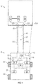
FIG. 1 is a schematic of a taxi tug having auxiliary power services interfacing with an aircraft; and -
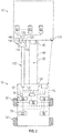
FIG. 2 is a flowchart of a method of operating the taxi tug having auxiliary power services. - Referring now to the Figures, where the present disclosure will be described with reference to specific embodiments, without limiting same, it is to be understood that the disclosed embodiments are merely illustrative of the present disclosure that may be embodied in various and alternative forms. The figures are not necessarily to scale; some features may be exaggerated or minimized to show details of particular components. Therefore, specific structural and functional details disclosed herein are not to be interpreted as limiting, but merely as a representative basis for teaching one skilled in the art to variously employ the present disclosure.
- Commercial aircraft typically expend 2-3% of mission fuel burn during taxi. Idling aircraft engines during taxi and other non-flight operations are inefficient and polluting. At partial load, aircraft engines emit hydrocarbons and carbon monoxide because of low combustion temperatures that discourage complete combustion. Anticipated global air traffic growth may exacerbate these problems if unchecked. Referring to
FIG. 1 , ataxi tug 10 provides auxiliary power services to anaircraft 12 and may save airlines 2-3% in fuel burn, reduce emissions, and decrease noise by providing auxiliary power services without operation of the aircraft engine or auxiliary power unit. - The
taxi tug 10 is configured to provide motive power to move theaircraft 12 as well as auxiliary power services to power aircraft loads during taxi so that no power flows from the aircraft main engines or the aircraft auxiliary power unit. Thetaxi tug 10 provides auxiliary power unit services beyond the terminal gates while simultaneously performing aircraft taxi functions. The provision of these services by thetaxi tug 10 may greatly reduce airport pollutants, fuel burn, and noise. - The
taxi tug 10 is configured to engage a main gear or nose gear assembly of theaircraft 12 to push or pull theaircraft 12 to a desired location. Thetaxi tug 10 provides the motive force when the aircraft is not under aircraft engine power. Thetaxi tug 10 includes achassis 20 and a push member ortow member 22. - The
chassis 20 includes at least onesteerable wheel 30 and at least onedrive wheel 32. Thechassis 20 is at least partially supported by the at least onesteerable wheel 30 and at least onedrive wheel 32. - The push member or
tow member 22 includes abar 40 that extends from the chassis that mechanically interfaces with at least one of a nose gear assembly, a main gear assembly, a wheel, or other part of the aircraft. In at least one embodiment, the push member ortow member 22 is configured to be coupled to a feature of the aircraft such as a hitch extending from the aircraft fuselage or may be a sling or other type of support member that engages the aircraft fuselage. In at least one embodiment, the push member ortow member 22 is configured as a cradle or platform that receives and upon which an aircraft wheel of either the nose landing gear assembly or the mainlanding gear assembly 42 rests. The push member ortow member 22 is configured to transfer motive power from thetaxi tug 10 to theaircraft 12 to move theaircraft 12. - The
taxi tug 10 includes an auxiliarypower services system 50 that includes amotive power source 52, apneumatic power source 54, and anelectrical power source 56. Themotive power source 52 is operatively connected to the at least onedrive wheel 32. Themotive power source 52 is configured to drive the at least onedrive wheel 32 to move thetaxi tug 10 and enables thetaxi tug 10 to push or tow theaircraft 12. In at least one embodiment, themotive power source 52 is configured to provide electricity to power a motor-generator 60 of theaircraft 12. - The
motive power source 52 may include a drive train having an electric, hybrid electric, hybrid electric diesel (ULSD), hybrid turbo-electric, and an electric fuel cell (Polymer Exchange Membrane or Solid Oxide Fuel Cell). - The
pneumatic power source 54 may be a pneumatic system that provides pneumatic power in the form of compressed air to theaircraft 12 through a supply duct or supply line. In at least one embodiment, the supply duct or supply line runs along or runs through the push member ortow member 22. Thepneumatic power source 54 may provide high pressure air to theaircraft 12 to run an air management system such as anenvironmental control system 62, to start the aircraft main engines, and to prevent ice buildup on the wings. In at least one embodiment, thepneumatic power source 54 may also provide conditioned low pressure air from a low-pressure pack 70 located on the taxi tug. The low-pressure pack 70 is configured to condition ambient air that is received by heating, cooling, and/or varying the humidity of ambient air and providing the conditioned air to theenvironmental control system 62 of theaircraft 12. Thepneumatic power source 54 may be a separate compressor driven off of themotive power source 52 or driven by theelectrical power source 56, etc. - The
electrical power source 56 is configured to provide any form of electricity to the aircraft 12 (e.g. 115 VAC/400 Hz and others) through a cable. In at least one embodiment, the cable and associated supply line runs along or runs through the push member ortow member 22. Theelectrical power source 56 is configured to provide electrical power to an aircraftelectric architecture 80 that is electrically connected to theenvironmental control system 62, that is electrically connected to a starter for the aircraft main engines, and that may be electrically connected to a heater disposed within or on the wings to prevent ice buildup on the wings. - The
taxi tug 10 includes anenergy storage system 90. Theenergy storage system 90 is at least one of a fuel storage system that is operatively connected to themotive power source 52 and a battery system that is operatively connected to theelectrical power source 56 and stores electrical power produced by theelectrical power source 56. - The
taxi tug 10 further includes amonitoring system 100 that monitors the transfer of auxiliary power services to the aircraft. Themonitoring system 100 is configured to monitor and regulate the transfer of pressurized air provided by thepneumatic power source 54 to theaircraft 12. For example, the air pressure in the supply duct or supply line may be monitored and the signal may be provided back to thepneumatic power source 54 to vary or maintain the air pressure. Themonitoring system 100 is further configured to monitor and regulate the transfer of electric power provided by theelectrical power source 56 to theaircraft 12. For example, the voltage, the current, or the power supplied through the electrical connector may be monitored and the signal may be provided back to theelectrical power source 56 to vary or maintain the voltage, the current, or the power. - The
taxi tug 10 further includes acommunication system 110. Thecommunication system 110 is configured to communicate with taxi tugs, theaircraft 12, the terminal, or air traffic control. Thecommunication system 110 may be a wireless communication system. - The
communication system 110 is arranged to provide signals indicative of a level of electric power available, air pressure available, energy storage level, status of the taxi tug 10 (e.g. online or offline), a position/path of thetaxi tug 10, or the like to other taxi tugs, theaircraft 12, the terminal, or air traffic control. Thecommunication system 110 is arranged to receive information or signals indicative of the state of an aircraft main engine (e.g. on/off, starting/shutting down). Thecommunication system 110 enables the taxi tug to avoid impact events or other incidents with other taxi tugs. In at least one embodiment, thetaxi tug 10 communicates with air traffic control to coordinate the wireless maneuvering of thetaxi tug 10. - The
communication system 110 may further include adata transfer module 112 that is configured to transfer data to or from acommunication module 114 disposed on theaircraft 12. The data transferred may be used in prognostics and health monitoring (PHIM), performance analysis, pre-flight or post-flight checks, navigation, etc. The data transfer may be performed wirelessly or through wired connections. - The
taxi tug 10 may interface with electric systems, landing gear, and air management systems of theaircraft 12. Thetaxi tug 10 includes appropriate interfaces that are configured to interface with the electric systems, the landing gear, and air management systems of the aircraft. Thetaxi tug 10 includes at least onepneumatic connector 116 and at least oneelectrical power connector 118. The at least onepneumatic connector 116 and the at least oneelectrical power connector 118 are arranged to interface with a power receptacle such as apneumatic port 120 disposed on theaircraft 12 and a power receptacle 122 (electrical power receptacle) of theaircraft 12, respectively. Thetaxi tug 10 is configured to accommodate the different locations of thepneumatic port 120 and theelectrical power receptacle 122. In at least one embodiment, thepneumatic port 120 and/or theelectrical power receptacle 122 are disposed on the mainlanding gear assembly 42. - Power for ground operation of the
environmental control system 62, the aircraftelectric architecture 80, a lighting system, hydraulic electric motor pumps, aircraft communication systems, aircraft navigation systems, lavatory operation, engine start, auxiliary power unit, and other requirements may be provided by thetaxi tug 10. The aircraft auxiliary power unit and the aircraft main engine need not be operated when thetaxi tug 10 is engaged and/or connected to theaircraft 12. - Prior to aircraft take off, the
taxi tug 10 may interface with theaircraft 12 at the gate, perform the aircraft pushback function, and tow the aircraft to the runway, all while providing pneumatic power, electric power, or other auxiliary power services to theaircraft 12 so that the main engines and the auxiliary power unit remain off. Prior to disconnection, power from thetaxi tug 10 may start at least one main engine of theaircraft 12. Since aircraft engines warm-up prior to takeoff, thetaxi tug 10 decouples from theaircraft 12 to permit aircraft engine warm-up. - Upon aircraft landing, the
taxi tug 10 may meet theaircraft 12 on the runway or taxiway. Thetaxi tug 10 and theaircraft 12 establish interfaces via thepneumatic port 120 and theelectrical power receptacle 122, the aircraft main engines may be turned off, and thetaxi tug 10 tows theaircraft 12 to a destination while providing auxiliary or main power services. In order for the pilot to retain control of theaircraft 12, electricity from thetaxi tug 10 may be provided to theaircraft 12 for the purpose of electric taxi. In this case, provisions are made so that thetaxi tug 10 andaircraft 12 maintain a safe separation distance. - The
taxi tug 10 decreases the aircraft main engine operation at partial load, which saves approximately 2% to 3% of fuel and decreases local emissions. Noise is also reduced because thetaxi tug 10 may also be operated electrically and/or outfitted with noise abatement measures. The inhibition of operation of the aircraft main engines reduces the possibility of the ingestion of foreign objects by the aircraft main engines. A highercapability taxi tug 10 may eliminate the need for aircraft auxiliary power unit operation for pneumatic, electric, and shaft power at the gates. - Referring to
FIG. 2 , thetaxi tug 10 is configured to autonomously interface with theaircraft 12. The autonomous or automated coupling and decoupling of auxiliary or main power services from thetaxi tug 10 to theaircraft 12 enhances safety of an operator of thetaxi tug 10 by autonomously coupling and decoupling the mechanical, electrical, and pneumatic interfaces. Thetaxi tug 10 includes acontrol module 130 that is in communication with themotive power source 52, thepneumatic power source 54, theelectrical power source 56, thecommunication system 110, amovable arm 132, aposition sensor 134, and aproximity sensor 136. - The at least one
pneumatic connector 116, the at least oneelectrical power connector 118, and theposition sensor 134 are disposed at a distal end of themovable arm 132. Responsive to a position signal provided by theproximity sensor 136 indicative of a position of thechassis 20 relative to theaircraft 12, thecontrol module 130 operates themotive power source 52 to drive the at least onedrive wheel 32 and to steer the at least onesteerable wheel 30 to position thechassis 20 proximate the chassis. Responsive to the position signal provided by theproximity sensor 136 indicating that thetaxi tug 10 is disposed proximate theaircraft 12 thecontrol module 130 operates or manipulates themovable arm 132 to move the at least onepneumatic connector 116 and the at least oneelectrical power connector 118 towards thepneumatic port 120 and theelectrical power receptacle 122, respectively. Theposition sensor 134 is configured to monitor or detect a position or a location of aposition feature 140 that is disposed on theaircraft 12 and is disposed proximate at least one of thepneumatic port 120 and theelectrical power receptacle 122. Thecontrol module 130 moves themovable arm 132, the at least onepneumatic connector 116, and the at least oneelectrical power connector 118 based on a location signal indicative of the location of the position feature 140 relative to theposition sensor 134 to connect the at least onepneumatic connector 116 to thepneumatic port 120 and to connect the at least oneelectrical power connector 118 to theelectrical power receptacle 122. - The position feature 140 may be an emitter configured to provide or emit a magnetic field, infrared waves, optical waves, or a radio frequency configured to be detected or received by the
position sensor 134. Theposition sensor 134 may be provided with a magnetic field sensor, an infrared receiver, a photodetector array, or radio receiver configured to receive the magnetic field, infrared waves, optical waves, or radio frequency emitted by theposition feature 140. - Responsive to the starting of the aircraft main engines and/or the
aircraft 12 being located at or proximate a gate, thecontrol module 130 may operate themovable arm 132 to disconnect the at least onepneumatic connector 116 from thepneumatic port 120 and to disconnect the at least oneelectrical power connector 118 from theelectrical power receptacle 122. - The
taxi tug 10 may also be applied to tugboats or other vessels. The taxi tug may be integrated with a tugboat that may not only move a watercraft, such as a ship, but may also provide electric power or other auxiliary power services so that the ship engines may be turned off while entering and/or exiting a port. - While the present disclosure has been described in detail in connection with only a limited number of embodiments, it should be readily understood that the present disclosure is not limited to such disclosed embodiments. Rather, the present disclosure can be modified to incorporate any number of variations, alterations, substitutions or equivalent arrangements not heretofore described, but which are within the scope of the present invention as defined by the claims. Additionally, while various embodiments of the present disclosure have been described, it is to be understood that aspects of the present disclosure may include only some of the described embodiments. Accordingly, the present disclosure is not to be seen as limited by the foregoing description, but is only limited by the scope of the appended claims.
Claims (15)
- A taxi tug for providing auxiliary power services, comprising:a chassis (20) having at least one drive wheel (32);a motive power source (10) operatively connected to the at least one drive wheel; andan auxiliary power services system (50) disposed on the chassis and configured to provide at least one of electric power, pneumatic power, and low pressure conditioned air to an aircraft.
- The taxi tug, of claim 1, further comprising:a tow member (22) extending from the chassis configured to selectively engage the aircraft.
- The taxi tug of claim 2, further comprising:at least one electrical power connector (118) arranged to interface with at least one power receptacle disposed on the aircraft.
- The taxi tug of claim 3, further comprising:an electrical power source (56) disposed on the chassis and operatively connected to the at least one power connector.
- The taxi tug of claim 4, wherein the electrical power source includes a cable that runs along the tow member and is operatively connected to the at least one power connector.
- The taxi tug of claim 2, further comprising:at least one pneumatic connector (116) arranged to interface with at least one pneumatic port disposed on the aircraft; and
- The taxi tug of claim 6, further comprising:a pneumatic power source (54) disposed on the chassis and operatively connected to the at least one pneumatic connector.
- The taxi tug of claim 7, wherein the pneumatic power source is arranged to provide compressed air to the aircraft for environmental control.
- The taxi tug of claim 7, wherein the pneumatic power source includes a supply line that runs along the tow member and is operatively connected to the at least one pneumatic connector.
- A taxi tug, comprising:a chassis (20);a motive power source (52) disposed on the chassis and operatively connected to at least one drive wheel;at least one of an electrical power source (56) having an electrical connector and a pneumatic power source (54) having a pneumatic connector disposed on the chassis;a proximity sensor (136) arranged to provide a position signal indicative of a position of the chassis relative to an aircraft; anda control module (130) disposed on the chassis, the control module programmed to operate the motive power source to drive the at least one drive wheel to position the chassis proximate the aircraft.
- The taxi tug of claim 10, further comprising:a movable arm (132) disposed on the chassis; anda tow member (22) disposed on the chassis and arranged to selectively engage an aircraft.
- The taxi tug of claim 11, further comprising:a position sensor (134) disposed proximate the distal end of the movable arm.
- The taxi tug of claim 12, wherein the position sensor is arranged to provide a location signal indicative of a location of a position feature disposed on the aircraft and is disposed proximate a power receptacle disposed on the aircraft.
- The taxi tug of claim 13, wherein the control module is further programmed to operate the movable arm based on the location signal to connect the at least one of the electrical connector and the pneumatic connector to the power receptacle.
- The taxi tug of claim 14, wherein the control module is further programmed to operate the movable arm to disconnect the at least one of the electrical connector and the pneumatic connector from the power receptacle, responsive to starting of an aircraft main engine.
Applications Claiming Priority (1)
| Application Number | Priority Date | Filing Date | Title |
|---|---|---|---|
| US201662310191P | 2016-03-18 | 2016-03-18 |
Publications (2)
| Publication Number | Publication Date |
|---|---|
| EP3219624A1 true EP3219624A1 (en) | 2017-09-20 |
| EP3219624B1 EP3219624B1 (en) | 2019-11-27 |
Family
ID=58401405
Family Applications (1)
| Application Number | Title | Priority Date | Filing Date |
|---|---|---|---|
| EP17161872.1A Active EP3219624B1 (en) | 2016-03-18 | 2017-03-20 | Taxi tug with auxiliary power services |
Country Status (2)
| Country | Link |
|---|---|
| US (1) | US10124911B2 (en) |
| EP (1) | EP3219624B1 (en) |
Cited By (1)
| Publication number | Priority date | Publication date | Assignee | Title |
|---|---|---|---|---|
| WO2020058522A3 (en) * | 2018-09-21 | 2020-08-06 | Octinion Bvba | Mobile drive unit and method of operation |
Families Citing this family (9)
| Publication number | Priority date | Publication date | Assignee | Title |
|---|---|---|---|---|
| EP3232533B1 (en) * | 2016-04-15 | 2019-09-18 | Airbus Operations GmbH | Ground support equipment for an aircraft video surveillance system |
| ES2771353T3 (en) * | 2017-04-05 | 2020-07-06 | Thyssenkrupp Airport Solutions S A | Device for providing air conditioning to an aircraft |
| US10460614B2 (en) * | 2018-01-11 | 2019-10-29 | Honeywell International Inc. | Methods system for real-time assessment and assistance of reduced engine taxi operations for an aircraft |
| DE102019117913A1 (en) * | 2019-07-03 | 2021-01-07 | Rheinmetall Landsysteme Gmbh | Device for starting and / or maintaining jet engines of aircraft and other aircraft (Stationary Air Power Unit - SAPU) |
| JP7172906B2 (en) * | 2019-07-31 | 2022-11-16 | トヨタ自動車株式会社 | airport and vehicle |
| US11760505B2 (en) * | 2019-10-09 | 2023-09-19 | The Boeing Company | Aircraft tow vehicles and methods of towing an aircraft |
| US20210354807A1 (en) * | 2020-05-13 | 2021-11-18 | Robert Blackmore Collins | Autonomous vehicle battery carrier to support electric aircraft taxiing and takeoff |
| US11772820B2 (en) | 2021-05-27 | 2023-10-03 | Pratt & Whitney Canada Corp. | Assist system and method for aircraft ground operation |
| WO2023178175A2 (en) * | 2022-03-16 | 2023-09-21 | Supernal, Llc | Systems, methods, and devices for ground maneuvering of aircraft |
Citations (10)
| Publication number | Priority date | Publication date | Assignee | Title |
|---|---|---|---|---|
| DE3423867A1 (en) * | 1984-06-28 | 1986-01-02 | Heinz 8132 Tutzing Schabmüller | Self-propelled on-board network supply system for aircraft |
| EP0206528A1 (en) * | 1985-05-28 | 1986-12-30 | Asset Traction Limited | Aircraft ground-handling vehicle |
| EP0350615A2 (en) * | 1988-07-13 | 1990-01-17 | SIMAI S.p.A. | Self-propelled, electricity generating, hybrid tractor for airport services, for checking the on-board aircraft equipment and for starting-up the aircraft engines |
| FR2675919A1 (en) * | 1991-04-25 | 1992-10-30 | Aerospatiale | Automated process and installation for moving an uncooperative object, especially for effecting ground movements of aircraft |
| US6424891B1 (en) * | 1999-03-31 | 2002-07-23 | The United States Of America As Represented By The Secretary Of The Air Force | Aircraft ground power unit |
| US20110073388A1 (en) * | 2009-09-29 | 2011-03-31 | Andres Michael J | Aircraft tug |
| US20110127366A1 (en) * | 2008-07-29 | 2011-06-02 | Andreas Becker | Automated system for maneuvering aircrafts on the ground |
| WO2011066891A1 (en) * | 2009-12-02 | 2011-06-09 | Diehl Aerospace Gmbh | Multi-function aircraft tractor |
| US20120045906A1 (en) * | 2010-08-11 | 2012-02-23 | John Bean Technologies Corporation | Aircraft GPU connection method and apparatus |
| US20150274323A1 (en) * | 2014-03-25 | 2015-10-01 | Parker-Hannifin Corporation | Aircraft ground support vehicle |
Family Cites Families (10)
| Publication number | Priority date | Publication date | Assignee | Title |
|---|---|---|---|---|
| SE411736B (en) * | 1974-06-15 | 1980-02-04 | Birkeholm Mogens | PROCEDURE AND DEVICE FOR TOWING A VEHICLE, EXAMPLE OF AN AIRPLANE |
| US4007890A (en) * | 1975-09-30 | 1977-02-15 | The Boeing Company | Aircraft towing braking system |
| US5381987A (en) * | 1994-05-31 | 1995-01-17 | Carns; William A. | Utility vehicle for towing and servicing aircraft |
| US6305484B1 (en) * | 2000-03-31 | 2001-10-23 | Leblanc Edward L. | Automated aircraft towing vehicle system |
| US9403604B2 (en) * | 2006-09-28 | 2016-08-02 | Israel Aerospace Industries Ltd. | System and method for transferring airplanes |
| JP5060884B2 (en) * | 2007-09-21 | 2012-10-31 | 富士重工業株式会社 | Traction equipment |
| SE539172C2 (en) * | 2013-03-13 | 2017-05-02 | Smart Climate Scandinavian Ab | Air conditioning intended to be temporarily connected to at least one aircraft |
| GB2516708B (en) * | 2013-12-24 | 2016-05-04 | Textron Ground Support Equipment Uk Ltd | Air conditioning system for an aircraft mover |
| US10202206B2 (en) * | 2014-12-04 | 2019-02-12 | General Electric Company | System and method for aircraft power management |
| FR3039520B1 (en) * | 2015-07-31 | 2018-11-02 | Airbus Sas | TRACTION VEHICLE FOR MANEUVERING AN AIRCRAFT AND FOR PROVIDING AIR PRESSURE TO AN AIRCRAFT DURING THE TAXI PHASE PRIOR TO TAKING OFF |
-
2017
- 2017-03-16 US US15/460,966 patent/US10124911B2/en active Active
- 2017-03-20 EP EP17161872.1A patent/EP3219624B1/en active Active
Patent Citations (10)
| Publication number | Priority date | Publication date | Assignee | Title |
|---|---|---|---|---|
| DE3423867A1 (en) * | 1984-06-28 | 1986-01-02 | Heinz 8132 Tutzing Schabmüller | Self-propelled on-board network supply system for aircraft |
| EP0206528A1 (en) * | 1985-05-28 | 1986-12-30 | Asset Traction Limited | Aircraft ground-handling vehicle |
| EP0350615A2 (en) * | 1988-07-13 | 1990-01-17 | SIMAI S.p.A. | Self-propelled, electricity generating, hybrid tractor for airport services, for checking the on-board aircraft equipment and for starting-up the aircraft engines |
| FR2675919A1 (en) * | 1991-04-25 | 1992-10-30 | Aerospatiale | Automated process and installation for moving an uncooperative object, especially for effecting ground movements of aircraft |
| US6424891B1 (en) * | 1999-03-31 | 2002-07-23 | The United States Of America As Represented By The Secretary Of The Air Force | Aircraft ground power unit |
| US20110127366A1 (en) * | 2008-07-29 | 2011-06-02 | Andreas Becker | Automated system for maneuvering aircrafts on the ground |
| US20110073388A1 (en) * | 2009-09-29 | 2011-03-31 | Andres Michael J | Aircraft tug |
| WO2011066891A1 (en) * | 2009-12-02 | 2011-06-09 | Diehl Aerospace Gmbh | Multi-function aircraft tractor |
| US20120045906A1 (en) * | 2010-08-11 | 2012-02-23 | John Bean Technologies Corporation | Aircraft GPU connection method and apparatus |
| US20150274323A1 (en) * | 2014-03-25 | 2015-10-01 | Parker-Hannifin Corporation | Aircraft ground support vehicle |
Cited By (1)
| Publication number | Priority date | Publication date | Assignee | Title |
|---|---|---|---|---|
| WO2020058522A3 (en) * | 2018-09-21 | 2020-08-06 | Octinion Bvba | Mobile drive unit and method of operation |
Also Published As
| Publication number | Publication date |
|---|---|
| US20170267377A1 (en) | 2017-09-21 |
| EP3219624B1 (en) | 2019-11-27 |
| US10124911B2 (en) | 2018-11-13 |
Similar Documents
| Publication | Publication Date | Title |
|---|---|---|
| US10124911B2 (en) | Taxi tug with auxiliary power services | |
| US8181725B2 (en) | Aircraft tug | |
| US8561939B2 (en) | Apparatus for taxiing an aircraft | |
| AU2017302225B2 (en) | Vertical take-off and landing aircraft | |
| CN108069043B (en) | Taxi vehicle for moving aircraft | |
| JP5072836B2 (en) | Power nose aircraft wheel system | |
| CN101553400B (en) | System and method for transferring airplanes | |
| US8788117B2 (en) | Method for moving an aircraft along the ground | |
| US20110290933A1 (en) | Aircraft including an undercarriage motor | |
| US20120217339A1 (en) | System and Method for Failsafe Operation of Aircraft Ground Movement System | |
| US9105186B2 (en) | Method for aiding the taxiing of an aircraft | |
| CN103543652A (en) | Monitoring and controlling unit of engine of unmanned aerial vehicle | |
| US10457281B2 (en) | Vehicle communication system | |
| US11479367B2 (en) | Assistance vehicle for assisting aircraft ground movements | |
| AU2017200920B2 (en) | Train control system having remote configuration interface | |
| US20140008488A1 (en) | Converter with taxi drive | |
| US20110073706A1 (en) | Aircraft tug | |
| US20160236693A1 (en) | Electric power supply system for machine | |
| CN102883951B (en) | Method and device for driving at least one landing gear wheel of an aircraft by means of a wheel motor | |
| CN209505553U (en) | A kind of comprehensive duties vehicle of unmanned plane | |
| CN203465855U (en) | Obstacle alarm system for unmanned plane | |
| JP2016524568A (en) | Aircraft capable of passing from the atmosphere to space and its method for automatically adapting its configuration | |
| US20230129585A1 (en) | Vehicle system with second power source | |
| US20230086453A1 (en) | Collision avoidance system | |
| CN116395143A (en) | Pilot abnormal operation monitoring and emergency treatment method |
Legal Events
| Date | Code | Title | Description |
|---|---|---|---|
| PUAI | Public reference made under article 153(3) epc to a published international application that has entered the european phase |
Free format text: ORIGINAL CODE: 0009012 |
|
| STAA | Information on the status of an ep patent application or granted ep patent |
Free format text: STATUS: THE APPLICATION HAS BEEN PUBLISHED |
|
| AK | Designated contracting states |
Kind code of ref document: A1 Designated state(s): AL AT BE BG CH CY CZ DE DK EE ES FI FR GB GR HR HU IE IS IT LI LT LU LV MC MK MT NL NO PL PT RO RS SE SI SK SM TR |
|
| AX | Request for extension of the european patent |
Extension state: BA ME |
|
| STAA | Information on the status of an ep patent application or granted ep patent |
Free format text: STATUS: REQUEST FOR EXAMINATION WAS MADE |
|
| 17P | Request for examination filed |
Effective date: 20180320 |
|
| RBV | Designated contracting states (corrected) |
Designated state(s): AL AT BE BG CH CY CZ DE DK EE ES FI FR GB GR HR HU IE IS IT LI LT LU LV MC MK MT NL NO PL PT RO RS SE SI SK SM TR |
|
| STAA | Information on the status of an ep patent application or granted ep patent |
Free format text: STATUS: EXAMINATION IS IN PROGRESS |
|
| 17Q | First examination report despatched |
Effective date: 20180813 |
|
| GRAP | Despatch of communication of intention to grant a patent |
Free format text: ORIGINAL CODE: EPIDOSNIGR1 |
|
| STAA | Information on the status of an ep patent application or granted ep patent |
Free format text: STATUS: GRANT OF PATENT IS INTENDED |
|
| INTG | Intention to grant announced |
Effective date: 20190618 |
|
| RAP1 | Party data changed (applicant data changed or rights of an application transferred) |
Owner name: HAMILTON SUNDSTRAND CORPORATION |
|
| GRAS | Grant fee paid |
Free format text: ORIGINAL CODE: EPIDOSNIGR3 |
|
| GRAA | (expected) grant |
Free format text: ORIGINAL CODE: 0009210 |
|
| STAA | Information on the status of an ep patent application or granted ep patent |
Free format text: STATUS: THE PATENT HAS BEEN GRANTED |
|
| AK | Designated contracting states |
Kind code of ref document: B1 Designated state(s): AL AT BE BG CH CY CZ DE DK EE ES FI FR GB GR HR HU IE IS IT LI LT LU LV MC MK MT NL NO PL PT RO RS SE SI SK SM TR |
|
| REG | Reference to a national code |
Ref country code: GB Ref legal event code: FG4D |
|
| REG | Reference to a national code |
Ref country code: CH Ref legal event code: EP |
|
| REG | Reference to a national code |
Ref country code: DE Ref legal event code: R096 Ref document number: 602017008998 Country of ref document: DE |
|
| REG | Reference to a national code |
Ref country code: AT Ref legal event code: REF Ref document number: 1206404 Country of ref document: AT Kind code of ref document: T Effective date: 20191215 |
|
| REG | Reference to a national code |
Ref country code: IE Ref legal event code: FG4D |
|
| REG | Reference to a national code |
Ref country code: NL Ref legal event code: MP Effective date: 20191127 |
|
| REG | Reference to a national code |
Ref country code: LT Ref legal event code: MG4D |
|
| PG25 | Lapsed in a contracting state [announced via postgrant information from national office to epo] |
Ref country code: GR Free format text: LAPSE BECAUSE OF FAILURE TO SUBMIT A TRANSLATION OF THE DESCRIPTION OR TO PAY THE FEE WITHIN THE PRESCRIBED TIME-LIMIT Effective date: 20200228 Ref country code: LT Free format text: LAPSE BECAUSE OF FAILURE TO SUBMIT A TRANSLATION OF THE DESCRIPTION OR TO PAY THE FEE WITHIN THE PRESCRIBED TIME-LIMIT Effective date: 20191127 Ref country code: NL Free format text: LAPSE BECAUSE OF FAILURE TO SUBMIT A TRANSLATION OF THE DESCRIPTION OR TO PAY THE FEE WITHIN THE PRESCRIBED TIME-LIMIT Effective date: 20191127 Ref country code: LV Free format text: LAPSE BECAUSE OF FAILURE TO SUBMIT A TRANSLATION OF THE DESCRIPTION OR TO PAY THE FEE WITHIN THE PRESCRIBED TIME-LIMIT Effective date: 20191127 Ref country code: SE Free format text: LAPSE BECAUSE OF FAILURE TO SUBMIT A TRANSLATION OF THE DESCRIPTION OR TO PAY THE FEE WITHIN THE PRESCRIBED TIME-LIMIT Effective date: 20191127 Ref country code: NO Free format text: LAPSE BECAUSE OF FAILURE TO SUBMIT A TRANSLATION OF THE DESCRIPTION OR TO PAY THE FEE WITHIN THE PRESCRIBED TIME-LIMIT Effective date: 20200227 Ref country code: FI Free format text: LAPSE BECAUSE OF FAILURE TO SUBMIT A TRANSLATION OF THE DESCRIPTION OR TO PAY THE FEE WITHIN THE PRESCRIBED TIME-LIMIT Effective date: 20191127 Ref country code: BG Free format text: LAPSE BECAUSE OF FAILURE TO SUBMIT A TRANSLATION OF THE DESCRIPTION OR TO PAY THE FEE WITHIN THE PRESCRIBED TIME-LIMIT Effective date: 20200227 |
|
| PG25 | Lapsed in a contracting state [announced via postgrant information from national office to epo] |
Ref country code: RS Free format text: LAPSE BECAUSE OF FAILURE TO SUBMIT A TRANSLATION OF THE DESCRIPTION OR TO PAY THE FEE WITHIN THE PRESCRIBED TIME-LIMIT Effective date: 20191127 Ref country code: HR Free format text: LAPSE BECAUSE OF FAILURE TO SUBMIT A TRANSLATION OF THE DESCRIPTION OR TO PAY THE FEE WITHIN THE PRESCRIBED TIME-LIMIT Effective date: 20191127 Ref country code: IS Free format text: LAPSE BECAUSE OF FAILURE TO SUBMIT A TRANSLATION OF THE DESCRIPTION OR TO PAY THE FEE WITHIN THE PRESCRIBED TIME-LIMIT Effective date: 20200327 |
|
| PG25 | Lapsed in a contracting state [announced via postgrant information from national office to epo] |
Ref country code: AL Free format text: LAPSE BECAUSE OF FAILURE TO SUBMIT A TRANSLATION OF THE DESCRIPTION OR TO PAY THE FEE WITHIN THE PRESCRIBED TIME-LIMIT Effective date: 20191127 |
|
| PG25 | Lapsed in a contracting state [announced via postgrant information from national office to epo] |
Ref country code: EE Free format text: LAPSE BECAUSE OF FAILURE TO SUBMIT A TRANSLATION OF THE DESCRIPTION OR TO PAY THE FEE WITHIN THE PRESCRIBED TIME-LIMIT Effective date: 20191127 Ref country code: PT Free format text: LAPSE BECAUSE OF FAILURE TO SUBMIT A TRANSLATION OF THE DESCRIPTION OR TO PAY THE FEE WITHIN THE PRESCRIBED TIME-LIMIT Effective date: 20200419 Ref country code: DK Free format text: LAPSE BECAUSE OF FAILURE TO SUBMIT A TRANSLATION OF THE DESCRIPTION OR TO PAY THE FEE WITHIN THE PRESCRIBED TIME-LIMIT Effective date: 20191127 Ref country code: CZ Free format text: LAPSE BECAUSE OF FAILURE TO SUBMIT A TRANSLATION OF THE DESCRIPTION OR TO PAY THE FEE WITHIN THE PRESCRIBED TIME-LIMIT Effective date: 20191127 Ref country code: ES Free format text: LAPSE BECAUSE OF FAILURE TO SUBMIT A TRANSLATION OF THE DESCRIPTION OR TO PAY THE FEE WITHIN THE PRESCRIBED TIME-LIMIT Effective date: 20191127 Ref country code: RO Free format text: LAPSE BECAUSE OF FAILURE TO SUBMIT A TRANSLATION OF THE DESCRIPTION OR TO PAY THE FEE WITHIN THE PRESCRIBED TIME-LIMIT Effective date: 20191127 |
|
| REG | Reference to a national code |
Ref country code: DE Ref legal event code: R097 Ref document number: 602017008998 Country of ref document: DE |
|
| PG25 | Lapsed in a contracting state [announced via postgrant information from national office to epo] |
Ref country code: SK Free format text: LAPSE BECAUSE OF FAILURE TO SUBMIT A TRANSLATION OF THE DESCRIPTION OR TO PAY THE FEE WITHIN THE PRESCRIBED TIME-LIMIT Effective date: 20191127 Ref country code: SM Free format text: LAPSE BECAUSE OF FAILURE TO SUBMIT A TRANSLATION OF THE DESCRIPTION OR TO PAY THE FEE WITHIN THE PRESCRIBED TIME-LIMIT Effective date: 20191127 |
|
| REG | Reference to a national code |
Ref country code: AT Ref legal event code: MK05 Ref document number: 1206404 Country of ref document: AT Kind code of ref document: T Effective date: 20191127 |
|
| REG | Reference to a national code |
Ref country code: DE Ref legal event code: R119 Ref document number: 602017008998 Country of ref document: DE |
|
| PLBE | No opposition filed within time limit |
Free format text: ORIGINAL CODE: 0009261 |
|
| STAA | Information on the status of an ep patent application or granted ep patent |
Free format text: STATUS: NO OPPOSITION FILED WITHIN TIME LIMIT |
|
| PG25 | Lapsed in a contracting state [announced via postgrant information from national office to epo] |
Ref country code: MC Free format text: LAPSE BECAUSE OF FAILURE TO SUBMIT A TRANSLATION OF THE DESCRIPTION OR TO PAY THE FEE WITHIN THE PRESCRIBED TIME-LIMIT Effective date: 20191127 |
|
| REG | Reference to a national code |
Ref country code: CH Ref legal event code: PL |
|
| 26N | No opposition filed |
Effective date: 20200828 |
|
| PG25 | Lapsed in a contracting state [announced via postgrant information from national office to epo] |
Ref country code: SI Free format text: LAPSE BECAUSE OF FAILURE TO SUBMIT A TRANSLATION OF THE DESCRIPTION OR TO PAY THE FEE WITHIN THE PRESCRIBED TIME-LIMIT Effective date: 20191127 Ref country code: PL Free format text: LAPSE BECAUSE OF FAILURE TO SUBMIT A TRANSLATION OF THE DESCRIPTION OR TO PAY THE FEE WITHIN THE PRESCRIBED TIME-LIMIT Effective date: 20191127 Ref country code: AT Free format text: LAPSE BECAUSE OF FAILURE TO SUBMIT A TRANSLATION OF THE DESCRIPTION OR TO PAY THE FEE WITHIN THE PRESCRIBED TIME-LIMIT Effective date: 20191127 |
|
| REG | Reference to a national code |
Ref country code: BE Ref legal event code: MM Effective date: 20200331 |
|
| PG25 | Lapsed in a contracting state [announced via postgrant information from national office to epo] |
Ref country code: LU Free format text: LAPSE BECAUSE OF NON-PAYMENT OF DUE FEES Effective date: 20200320 |
|
| PG25 | Lapsed in a contracting state [announced via postgrant information from national office to epo] |
Ref country code: CH Free format text: LAPSE BECAUSE OF NON-PAYMENT OF DUE FEES Effective date: 20200331 Ref country code: DE Free format text: LAPSE BECAUSE OF NON-PAYMENT OF DUE FEES Effective date: 20201001 Ref country code: LI Free format text: LAPSE BECAUSE OF NON-PAYMENT OF DUE FEES Effective date: 20200331 Ref country code: IT Free format text: LAPSE BECAUSE OF FAILURE TO SUBMIT A TRANSLATION OF THE DESCRIPTION OR TO PAY THE FEE WITHIN THE PRESCRIBED TIME-LIMIT Effective date: 20191127 Ref country code: IE Free format text: LAPSE BECAUSE OF NON-PAYMENT OF DUE FEES Effective date: 20200320 |
|
| PG25 | Lapsed in a contracting state [announced via postgrant information from national office to epo] |
Ref country code: BE Free format text: LAPSE BECAUSE OF NON-PAYMENT OF DUE FEES Effective date: 20200331 |
|
| PG25 | Lapsed in a contracting state [announced via postgrant information from national office to epo] |
Ref country code: TR Free format text: LAPSE BECAUSE OF FAILURE TO SUBMIT A TRANSLATION OF THE DESCRIPTION OR TO PAY THE FEE WITHIN THE PRESCRIBED TIME-LIMIT Effective date: 20191127 Ref country code: MT Free format text: LAPSE BECAUSE OF FAILURE TO SUBMIT A TRANSLATION OF THE DESCRIPTION OR TO PAY THE FEE WITHIN THE PRESCRIBED TIME-LIMIT Effective date: 20191127 Ref country code: CY Free format text: LAPSE BECAUSE OF FAILURE TO SUBMIT A TRANSLATION OF THE DESCRIPTION OR TO PAY THE FEE WITHIN THE PRESCRIBED TIME-LIMIT Effective date: 20191127 |
|
| PG25 | Lapsed in a contracting state [announced via postgrant information from national office to epo] |
Ref country code: MK Free format text: LAPSE BECAUSE OF FAILURE TO SUBMIT A TRANSLATION OF THE DESCRIPTION OR TO PAY THE FEE WITHIN THE PRESCRIBED TIME-LIMIT Effective date: 20191127 |
|
| PGFP | Annual fee paid to national office [announced via postgrant information from national office to epo] |
Ref country code: FR Payment date: 20230222 Year of fee payment: 7 |
|
| PGFP | Annual fee paid to national office [announced via postgrant information from national office to epo] |
Ref country code: GB Payment date: 20230222 Year of fee payment: 7 |
|
| P01 | Opt-out of the competence of the unified patent court (upc) registered |
Effective date: 20230522 |