EP3219616A1 - Modular monocoque backrest - Google Patents
Modular monocoque backrest Download PDFInfo
- Publication number
- EP3219616A1 EP3219616A1 EP17159520.0A EP17159520A EP3219616A1 EP 3219616 A1 EP3219616 A1 EP 3219616A1 EP 17159520 A EP17159520 A EP 17159520A EP 3219616 A1 EP3219616 A1 EP 3219616A1
- Authority
- EP
- European Patent Office
- Prior art keywords
- shroud
- restraint
- coupled
- back shroud
- front shroud
- Prior art date
- Legal status (The legal status is an assumption and is not a legal conclusion. Google has not performed a legal analysis and makes no representation as to the accuracy of the status listed.)
- Granted
Links
Images


Classifications
-
- B—PERFORMING OPERATIONS; TRANSPORTING
- B60—VEHICLES IN GENERAL
- B60N—SEATS SPECIALLY ADAPTED FOR VEHICLES; VEHICLE PASSENGER ACCOMMODATION NOT OTHERWISE PROVIDED FOR
- B60N2/00—Seats specially adapted for vehicles; Arrangement or mounting of seats in vehicles
- B60N2/68—Seat frames
- B60N2/686—Panel like structures
-
- B—PERFORMING OPERATIONS; TRANSPORTING
- B60—VEHICLES IN GENERAL
- B60N—SEATS SPECIALLY ADAPTED FOR VEHICLES; VEHICLE PASSENGER ACCOMMODATION NOT OTHERWISE PROVIDED FOR
- B60N2/00—Seats specially adapted for vehicles; Arrangement or mounting of seats in vehicles
- B60N2/64—Back-rests or cushions
-
- A—HUMAN NECESSITIES
- A47—FURNITURE; DOMESTIC ARTICLES OR APPLIANCES; COFFEE MILLS; SPICE MILLS; SUCTION CLEANERS IN GENERAL
- A47C—CHAIRS; SOFAS; BEDS
- A47C5/00—Chairs of special materials
- A47C5/12—Chairs of special materials of plastics, with or without reinforcement
-
- B—PERFORMING OPERATIONS; TRANSPORTING
- B60—VEHICLES IN GENERAL
- B60N—SEATS SPECIALLY ADAPTED FOR VEHICLES; VEHICLE PASSENGER ACCOMMODATION NOT OTHERWISE PROVIDED FOR
- B60N2/00—Seats specially adapted for vehicles; Arrangement or mounting of seats in vehicles
- B60N2/02—Seats specially adapted for vehicles; Arrangement or mounting of seats in vehicles the seat or part thereof being movable, e.g. adjustable
- B60N2/22—Seats specially adapted for vehicles; Arrangement or mounting of seats in vehicles the seat or part thereof being movable, e.g. adjustable the back-rest being adjustable
-
- B—PERFORMING OPERATIONS; TRANSPORTING
- B60—VEHICLES IN GENERAL
- B60N—SEATS SPECIALLY ADAPTED FOR VEHICLES; VEHICLE PASSENGER ACCOMMODATION NOT OTHERWISE PROVIDED FOR
- B60N2/00—Seats specially adapted for vehicles; Arrangement or mounting of seats in vehicles
- B60N2/64—Back-rests or cushions
- B60N2/66—Lumbar supports
-
- B—PERFORMING OPERATIONS; TRANSPORTING
- B60—VEHICLES IN GENERAL
- B60N—SEATS SPECIALLY ADAPTED FOR VEHICLES; VEHICLE PASSENGER ACCOMMODATION NOT OTHERWISE PROVIDED FOR
- B60N2/00—Seats specially adapted for vehicles; Arrangement or mounting of seats in vehicles
- B60N2/64—Back-rests or cushions
- B60N2/66—Lumbar supports
- B60N2/667—Lumbar supports having flexible support member bowed by applied forces
-
- B—PERFORMING OPERATIONS; TRANSPORTING
- B60—VEHICLES IN GENERAL
- B60N—SEATS SPECIALLY ADAPTED FOR VEHICLES; VEHICLE PASSENGER ACCOMMODATION NOT OTHERWISE PROVIDED FOR
- B60N2/00—Seats specially adapted for vehicles; Arrangement or mounting of seats in vehicles
- B60N2/68—Seat frames
- B60N2/682—Joining means
-
- B—PERFORMING OPERATIONS; TRANSPORTING
- B60—VEHICLES IN GENERAL
- B60N—SEATS SPECIALLY ADAPTED FOR VEHICLES; VEHICLE PASSENGER ACCOMMODATION NOT OTHERWISE PROVIDED FOR
- B60N2/00—Seats specially adapted for vehicles; Arrangement or mounting of seats in vehicles
- B60N2/68—Seat frames
- B60N2/688—Particular seat belt attachment and guiding
-
- B—PERFORMING OPERATIONS; TRANSPORTING
- B60—VEHICLES IN GENERAL
- B60R—VEHICLES, VEHICLE FITTINGS, OR VEHICLE PARTS, NOT OTHERWISE PROVIDED FOR
- B60R22/00—Safety belts or body harnesses in vehicles
- B60R22/34—Belt retractors, e.g. reels
- B60R22/36—Belt retractors, e.g. reels self-locking in an emergency
-
- B—PERFORMING OPERATIONS; TRANSPORTING
- B64—AIRCRAFT; AVIATION; COSMONAUTICS
- B64D—EQUIPMENT FOR FITTING IN OR TO AIRCRAFT; FLIGHT SUITS; PARACHUTES; ARRANGEMENT OR MOUNTING OF POWER PLANTS OR PROPULSION TRANSMISSIONS IN AIRCRAFT
- B64D11/00—Passenger or crew accommodation; Flight-deck installations not otherwise provided for
- B64D11/06—Arrangements of seats, or adaptations or details specially adapted for aircraft seats
- B64D11/062—Belts or other passenger restraint means for passenger seats
-
- B—PERFORMING OPERATIONS; TRANSPORTING
- B64—AIRCRAFT; AVIATION; COSMONAUTICS
- B64D—EQUIPMENT FOR FITTING IN OR TO AIRCRAFT; FLIGHT SUITS; PARACHUTES; ARRANGEMENT OR MOUNTING OF POWER PLANTS OR PROPULSION TRANSMISSIONS IN AIRCRAFT
- B64D11/00—Passenger or crew accommodation; Flight-deck installations not otherwise provided for
- B64D11/06—Arrangements of seats, or adaptations or details specially adapted for aircraft seats
- B64D11/0647—Seats characterised by special upholstery or cushioning features
-
- B—PERFORMING OPERATIONS; TRANSPORTING
- B64—AIRCRAFT; AVIATION; COSMONAUTICS
- B64D—EQUIPMENT FOR FITTING IN OR TO AIRCRAFT; FLIGHT SUITS; PARACHUTES; ARRANGEMENT OR MOUNTING OF POWER PLANTS OR PROPULSION TRANSMISSIONS IN AIRCRAFT
- B64D11/00—Passenger or crew accommodation; Flight-deck installations not otherwise provided for
- B64D11/06—Arrangements of seats, or adaptations or details specially adapted for aircraft seats
- B64D11/0649—Seats characterised by special features for reducing weight
-
- Y—GENERAL TAGGING OF NEW TECHNOLOGICAL DEVELOPMENTS; GENERAL TAGGING OF CROSS-SECTIONAL TECHNOLOGIES SPANNING OVER SEVERAL SECTIONS OF THE IPC; TECHNICAL SUBJECTS COVERED BY FORMER USPC CROSS-REFERENCE ART COLLECTIONS [XRACs] AND DIGESTS
- Y02—TECHNOLOGIES OR APPLICATIONS FOR MITIGATION OR ADAPTATION AGAINST CLIMATE CHANGE
- Y02T—CLIMATE CHANGE MITIGATION TECHNOLOGIES RELATED TO TRANSPORTATION
- Y02T50/00—Aeronautics or air transport
- Y02T50/40—Weight reduction
Definitions
- the present disclosure relates to seats, and more specifically, to a seat with a modular monocoque backrest.
- a typical backrest may comprise an aluminum or metallic frame with shear panels, side beams, and cross bars to take inflight stress loads and crash loads.
- a heavy torque tube may also be introduced in the lumbar area, to take torsional loads in the forward direction caused by an asymmetric shoulder belt. Due to the amount of heavy metallic materials used, typical backrest structures may be heavy and costly.
- a seat backrest may comprise a front shroud.
- the front shroud may be formed from a first molded carbon fiber composite.
- the seat backrest may also comprise a back shroud.
- the back shroud may be coupled to the front shroud, and may be formed from a second molded carbon fiber composite.
- the seat backrest may also comprise an at least one back spar.
- the at least one back spar may be coupled between the front shroud and the back shroud, and may extend in a direction away from the front shroud and the back shroud.
- the seat backrest may also further comprise the following.
- a headrest bracket may be coupled at a first end to the back shroud, and at a second end to the front shroud.
- a lumbar support mechanism may be coupled to the front shroud.
- a restraint exit may be coupled to the back shroud.
- the restraint exit may define a void on the back shroud, and the void may be configured to allow passage of a shoulder restraint belt.
- a restraint inertia reel may be coupled to the back shroud.
- the restraint inertia reel may be configured to deploy and retract the shoulder restraint belt through the restraint exit.
- the restraint exit may comprise a restraint support having a top surface opposite of a bottom surface.
- the bottom surface may be coupled to the back shroud.
- a restraint bezel may be coupled to the top surface.
- the restraint exit may comprise the second carbon fiber composite material.
- the restraint exit may be molded with the back shroud such that the back shroud and the restraint exit comprise a single continuous part.
- the at least one back spar may comprise an aluminum material.
- the at least one back spar may comprise a plurality of cross bracings.
- a modular monocoque backrest may comprise a front shroud.
- the front shroud may have a cushion support surface opposite of a first connecting surface.
- the front shroud may comprise a first carbon fiber composite material.
- the modular monocoque backrest may comprise a back shroud.
- the back shroud may have a second connecting surface opposite of a back surface.
- the back shroud may comprise a second carbon fiber composite material.
- the second connecting surface of the back shroud may be integrally couple to the first connecting surface of the front shroud, such that the front shroud and the back shroud form a single integrated object.
- the modular monocoque backrest may also comprise an at least one back spar.
- the at least one back spar may have a top end opposite of a bottom end.
- the top end may be configured to couple at a first edge to the first connecting surface of the front shroud and couple at a second edge to the second connecting surface of the back shroud.
- the bottom end may extend in a direction away from the front shroud and the back shroud.
- the modular monocoque backrest may also further comprise the following.
- a headrest bracket may be coupled at a first end to the second connecting surface of the back shroud and coupled at a second end to the first connecting surface of the front shroud.
- a lumbar support mechanism may be coupled to the cushion support surface of the front shroud.
- a restraint exit may be coupled to a top of the back shroud. The restraint exit may define a void on the top of the back shroud, configured to allow passage of a shoulder restraint belt.
- a restraint inertia reel may be coupled to the second connecting surface of the back shroud. The restraint inertia reel may be configured to deploy and retract the shoulder restraint belt through the restraint exit.
- the restraint exit may comprise a restraint support coupled to the top of the back shroud and a restraint bezel coupled to the top of the restraint support.
- the restraint exit may comprise the second carbon fiber composite material.
- the restraint exit may be molded with the back shroud such that the back shroud and the restraint exit comprise a single continuous part.
- the at least one back spar may comprise an aluminum material.
- the at least one back spar may comprise a plurality of cross bracings.
- a method of manufacturing a modular monocoque backrest may comprise forming a front shroud having a cushion support surface opposite of a first connecting surface.
- the front shroud may comprise a first carbon fiber composite material.
- the method may comprise forming a back shroud having a second connecting surface opposite of a back surface.
- the back shroud may comprise a second carbon fiber composite material.
- the method may comprise coupling the first connecting surface of the front shroud to the second connecting surface of the back shroud.
- the method may also comprise coupling an at least one back spar to the front shroud and the back shroud.
- the back shroud may comprise a top end opposite of a bottom end.
- the top end may be configured to couple at a first edge to the first connecting surface of the front shroud and couple at a second edge to the second connecting surface of the back shroud.
- the bottom end may extend in a direction away from the front shroud and the back shroud.
- the front shroud may be coupled to the back shroud via an epoxy adhesive.
- any of the method or process descriptions may be executed in any order and are not necessarily limited to the order presented.
- any reference to singular includes plural embodiments, and any reference to more than one component or step may include a singular embodiment or step.
- any reference to attached, fixed, coupled, connected or the like may include permanent, removable, temporary, partial, full and/or any other possible attachment option.
- any reference to without contact (or similar phrases) may also include reduced contact or minimal contact. Surface shading lines may be used throughout the figures to denote different parts but not necessarily to denote the same or different materials.
- a modular monocoque backrest 100 is disclosed.
- Modular monocoque backrest 100 may be configured to provide a structure that is lighter in weight than conventional backrest structures, while also maintaining resistance to dynamic crash loads. Moreover, modular monocoque backrest 100 may also allow for exterior styling and decorative features without the need for additional exterior shrouding parts.
- modular monocoque backrest 100 may comprise any suitable lightweight and structurally durable material.
- modular monocoque backrest 100 may comprise a carbon fiber composite.
- Modular monocoque backrest 100 may also comprise a composite reinforcement material such as fiberglass and/or phenolic. Modular monocoque backrest 100 may be fabricated using any suitable carbon fiber manufacturing technique.
- modular monocoque backrest 100 may be fabricated using a carbon fiber layup method, and molded into any desired shape and/or size. Any suitable layup method may be used to fabricate modular monocoque backrest 100. Modular monocoque backrest 100 may also comprise any suitable coating and/or cover. For example, modular monocoque backrest 100 may be wrapped in leather, and/or any other suitable material, as desired.
- a carbon fiber composite molded design may enable modular monocoque backrest 100 to distribute and support stress loads through the external body of modular monocoque backrest 100, without the need for additional metallic components for reinforcement.
- a carbon fiber composite molded design may also enable modular monocoque backrest 100 to modularly incorporate additional design features into the molded design, eliminating the need for additional external mounting brackets, hardware, and/or the like.
- modular monocoque backrest 100 may be molded to comprise a back literature pocket.
- Modular monocoque backrest 100 may also be molded to further comprise mounting brackets for a back literature pocket, and the back literature pocket may be fastened on.
- Modular monocoque backrest 100 may also be molded to comprise mounting provisions for speakers, lights, heating and/or cooling elements, arm rests, and/or any other suitable accessory.
- the use of a carbon fiber composite molded design may also enable modular monocoque backrest 100 to mold into any desired shape and/or size. Desired exterior styling and designs may therefore be incorporated without the need for extra exterior shrouding parts.
- modular monocoque backrest 100 may further distribute and support stress loads by incorporating support materials.
- support materials may be added to the interior of modular monocoque backrest 100, in a position inward from the outer surfaces.
- modular monocoque backrest 100 may comprise a support material in the interior having a honeycomb structure.
- the honeycomb structure may comprise a carbon fiber material, and/or any other suitable material cable of providing further support to modular monocoque backrest 100.
- the honeycomb structure may comprise a separate object from modular monocoque backrest 100, or the honeycomb structure may also integrate with modular monocoque backrest 100.
- a foam core may also be implemented in the interior of modular monocoque backrest 100. The foam core may be configured to further distribute and support stress loads.
- modular monocoque backrest 100 may comprise a front shroud 110, a back shroud 120, and a back spar 130.
- Front shroud 110 may be configured to provide structural support to modular monocoque backrest 100.
- front shroud 110 may comprise a cushion support surface 112 and a connecting surface 114.
- Cushion support surface 112 may comprise an outer surface of modular monocoque backrest 100 after front shroud 110 is coupled to back shroud 120.
- Cushion support surface 112 may be configured to couple to a cushion, pad, and/or the like.
- Connecting surface 114 may comprise an inner surface of modular monocoque backrest 100 after front shroud 110 is coupled to back shroud 120.
- connecting surface 114 may be configured as the surface of front shroud 110 that couples to back shroud 120.
- back shroud 120 may be configured to provide further structural support to modular monocoque backrest 100.
- Back shroud 120 may comprise a connecting surface 122 and a back surface 124.
- Connecting surface 122 may comprise an inner surface of modular monocoque backrest 100 after front shroud 110 is coupled to back shroud 120.
- connecting surface 122 may be configured as the surface of back shroud 120 that couples to front shroud 110.
- Back surface 124 may comprise an outer surface of modular monocoque backrest 100 after front shroud 110 is coupled to back shroud 120.
- front shroud 110 may be configured to couple to back shroud 120.
- connecting surface 114 of front shroud 110 may be configured to couple to connecting surface 122 of back shroud 120.
- Front shroud 110 may be coupled to back shroud 120 using any suitable technique.
- front shroud 110 may couple to back shroud 120 using an adhesive and/or bonding agent, such as an epoxy used for composite bonding, a resin, a thermoset, and/or a thermoplastic.
- Front shroud 110 may also couple to back shroud 120 using a mechanical fastener, such as a rivet, screw, and/or the like.
- Mechanical fasteners may be used at various intervals around the perimeter of modular monocoque backrest 100 to ensure a secure coupling between front shroud 110 and back shroud 120.
- mechanical fasteners may be used at about every one inch (25.4 mm), two inches (50.8 mm), and/or any other suitable and/or desired interval.
- front shroud 110 may be coupled to back shroud 120 using a combination of coupling techniques, such as, for example, through the use of both an adhesive and a mechanical fastener.
- back spar 130 may provide a mounting point to mount modular monocoque backrest 100 to a surface, such as an aircraft floor, for example. Back spar 130 may also provide additional structural support for modular monocoque backrest 100 against torsional loads, inflight abuse loads, and/or crash loads. Back spar 130 may protrude downward from front shroud 110 and back shroud 120.
- modular monocoque backrest 100 may comprise a plurality of back spars 130.
- Back spar 130 may comprise any suitable material.
- back spar 130 may comprise a metal material, such as aluminum.
- back spar 130 may also comprise a carbon fiber material.
- Back spar 130 may be molded into front shroud 110 and/or back shroud 120, such that back spar 130 and front shroud 110 and/or back shroud 120 may form a single continuous part.
- back spar 130, front shroud 110, and back shroud 120 may form an integral component in modular monocoque backrest 100.
- back spar 130 may comprise a top end 132 opposite of a bottom end 134.
- Top end 132 may comprise the end of back spar 130 proximate to modular monocoque backrest 100
- bottom end 134 may comprise the end of back spar 130 located furthest away from modular monocoque backrest 100.
- Top end 132 may be configured to couple back spar 130 to modular monocoque backrest 100.
- Top end 132 may be configured to couple to front shroud 110 and/or back shroud 120.
- Top end 132 may be coupled to front shroud 110 and back shroud 120 using any suitable method, such as via a mechanical fastener.
- Top end 132 may be inserted between the coupling of front shroud 110 and back shroud 120, and couple at a first edge to connecting surface 114 of front shroud 110 and at a second edge to connecting surface 122 of back shroud 120.
- Bottom end 134 may comprise the mounting point for back spar 130, and may be configured to mount to a surface, such as an aircraft floor for example.
- Back spar 130 may also comprise a plurality of cross bracings 137, configured to provide additional structural support to modular monocoque backrest 100.
- Cross bracings 137 may comprise a plurality of voids on the inner surface of back spar 130, configured to increase the structural strength of back spar 130. In this regard, the use of cross bracings 137 may also allow for a lighter weight back spar 130.
- modular monocoque backrest 100 may also comprise a headrest bracket 140.
- Headrest bracket 140 may be configured to receive a headrest (e.g., through headrest support holes 270, as depicted in FIG. 2A ) and provide structural support for the headrest.
- headrest bracket 140 may comprise a plurality of voids 145 configured to receive and secure a headrest.
- Headrest bracket 140 may comprise any suitable material.
- headrest bracket 140 may comprise an aluminum material.
- Headrest bracket 140 may be coupled to connecting surface 114 of front shroud 110 and connecting surface 122 of back shroud 120, such that headrest bracket 140 may fit between the coupling of front shroud 110 to back shroud 120.
- headrest bracket 140 may also comprise a carbon fiber material. Headrest bracket may be molded directly with back shroud 120, such that back shroud 120 and headrest bracket 140 may comprise a single continuous part. In this regard, headrest bracket 140, front shroud 110, and back shroud 120 may form an integral component in modular monocoque backrest 100.
- a modular monocoque backrest 200 further comprising restraint devices is disclosed.
- modular monocoque backrest 200 may comprise a variety of restraint and safety devices and/or mechanisms.
- a restraint inertia reel 250 may be configured to deploy and retract a shoulder restraint belt 255.
- Restraint inertia reel 250 may comprise a spring-loaded reel capable of deploying and retracting shoulder restraint belt 255.
- Restraint inertia reel 250 may also comprise an inertial locking mechanism, or other such similar apparatus and/or mechanism, capable of preventing shoulder restraint belt 255 from deploying further during a sudden acceleration.
- Restraint inertia reel 250 may be coupled to connecting surface 122 of back shroud 120. Restraint inertia reel 250 may be coupled to connecting surface 122 of back shroud 120 using a mounting bracket, bolt, and/or the like. In various embodiments, connecting surface 122 of back shroud 120 may be molded to comprise a mounting bracket for restraint inertia reel 250. In that regard, restraint inertia reel 250 may bolt on to connecting surface 122 without the need for additional hardware and/or mounting brackets.
- shoulder restraint belt 255 may deploy from restraint inertia reel 250 through a restraint exit 260. Shoulder restraint belt 255 may then be configured to connect to a female safety attachment member, such as restraint buckle and/or the like, located on a seat.
- Restraint exit 260 may comprise any suitable material, such as aluminum.
- restraint exit 260 may also comprise a carbon fiber material.
- restraint exit 260 may be molded directly into back shroud 120, such that back shroud 120 and restraint exit 260 comprise a single continuous part. Restraint exit 260 may comprise a restraint support 268 and a restraint bezel 264.
- Restraint support 268 may be configured to structurally guide and support shoulder restraint belt 255 while deployed. Restraint support 268 may be coupled to the top of back shroud 120. In this regard, back shroud 120 may be molded to comprise a void and restraint support 268 may substantially align with the void to allow shoulder restraint belt 255 to pass through the top of back shroud 120. Restraint bezel 264 may be configured to protect restraint support 268 and to provide structural support for shoulder restraint belt 255 after shoulder restraint belt 255 is deployed. Restraint bezel 264 may also be decorative in nature, comprising a metal plating and/or the like.
- a modular monocoque backrest 300 further comprising a lumbar support mechanism 380 is depicted.
- Lumbar support mechanism 380 may be coupled to cushion support surface 112 of front shroud 110.
- Lumbar support mechanism 380 may be located in any suitable location on cushion support surface 112, such as, for example, in the general lumbar region of cushion support surface 112.
- Lumbar support mechanism 380 may couple to cushion support surface 112 using any suitable technique, such as via a mounting bracket, fastener, bolt, and/or the like.
- cushion support surface 112 may also be molded to comprise mounting brackets, and/or the like, enabling lumbar support mechanism 380 to couple to cushion support surface 112 without the need of additional hardware and/or mounting brackets.
- lumbar support mechanism 380 may be configured to adjustably vary the amount of lumbar support in modular monocoque backrest 300.
- lumbar support mechanism 380 may adjust to protrude outward from front shroud 110. The outward protrusion may provide a passenger with greater support and comfort in the lumbar region.
- the adjusted lumbar support mechanism 380 may protrude outward causing a curvature of the cushion in the lumbar area.
- Lumbar support mechanism 380 may also comprise a mechanical and/or electrical device allowing for adjustment to the level of outward protrusion.
- lumbar support mechanism 380 may allow for a change in the protrusion amount to vary the distance lumbar support mechanism 380 is protruding away from front shroud 110.
- Lumbar support mechanism 380 may be adjusted using any suitable device, such as, for example, through electronic controls, mechanical controls, and/or the like.
- references to "various embodiments”, “one embodiment”, “an embodiment”, “an example embodiment”, etc. indicate that the embodiment described may include a particular feature, structure, or characteristic, but every embodiment may not necessarily include the particular feature, structure, or characteristic. Moreover, such phrases are not necessarily referring to the same embodiment. Further, when a particular feature, structure, or characteristic is described in connection with an embodiment, it is submitted that it is within the knowledge of one skilled in the art to affect such feature, structure, or characteristic in connection with other embodiments whether or not explicitly described. After reading the description, it will be apparent to one skilled in the relevant art(s) how to implement the disclosure in alternative embodiments.
- the terms “comprises”, “comprising”, or any other variation thereof, are intended to cover a non-exclusive inclusion, such that a process, method, article, or apparatus that comprises a list of elements does not include only those elements but may include other elements not expressly listed or inherent to such process, method, article, or apparatus.
Landscapes
- Engineering & Computer Science (AREA)
- Aviation & Aerospace Engineering (AREA)
- Mechanical Engineering (AREA)
- Transportation (AREA)
- Seats For Vehicles (AREA)
- Chair Legs, Seat Parts, And Backrests (AREA)
- Vibration Dampers (AREA)
Abstract
Description
- The present disclosure relates to seats, and more specifically, to a seat with a modular monocoque backrest.
- Traditional aircraft passenger seats may use heavy metallic materials in the backrest structure to endure various stress loads and to create a sufficient load bearing system. A typical backrest may comprise an aluminum or metallic frame with shear panels, side beams, and cross bars to take inflight stress loads and crash loads. A heavy torque tube may also be introduced in the lumbar area, to take torsional loads in the forward direction caused by an asymmetric shoulder belt. Due to the amount of heavy metallic materials used, typical backrest structures may be heavy and costly.
- In various embodiments, a seat backrest is disclosed. The seat backrest may comprise a front shroud. The front shroud may be formed from a first molded carbon fiber composite. The seat backrest may also comprise a back shroud. The back shroud may be coupled to the front shroud, and may be formed from a second molded carbon fiber composite. The seat backrest may also comprise an at least one back spar. The at least one back spar may be coupled between the front shroud and the back shroud, and may extend in a direction away from the front shroud and the back shroud.
- In various embodiments, the seat backrest may also further comprise the following. A headrest bracket may be coupled at a first end to the back shroud, and at a second end to the front shroud. A lumbar support mechanism may be coupled to the front shroud. A restraint exit may be coupled to the back shroud. The restraint exit may define a void on the back shroud, and the void may be configured to allow passage of a shoulder restraint belt. A restraint inertia reel may be coupled to the back shroud. The restraint inertia reel may be configured to deploy and retract the shoulder restraint belt through the restraint exit. The restraint exit may comprise a restraint support having a top surface opposite of a bottom surface. The bottom surface may be coupled to the back shroud. A restraint bezel may be coupled to the top surface. The restraint exit may comprise the second carbon fiber composite material. In this regard, the restraint exit may be molded with the back shroud such that the back shroud and the restraint exit comprise a single continuous part. The at least one back spar may comprise an aluminum material. The at least one back spar may comprise a plurality of cross bracings.
- In various embodiments, a modular monocoque backrest is disclosed. The modular monocoque backrest may comprise a front shroud. The front shroud may have a cushion support surface opposite of a first connecting surface. The front shroud may comprise a first carbon fiber composite material. The modular monocoque backrest may comprise a back shroud. The back shroud may have a second connecting surface opposite of a back surface. The back shroud may comprise a second carbon fiber composite material. The second connecting surface of the back shroud may be integrally couple to the first connecting surface of the front shroud, such that the front shroud and the back shroud form a single integrated object. The modular monocoque backrest may also comprise an at least one back spar. The at least one back spar may have a top end opposite of a bottom end. The top end may be configured to couple at a first edge to the first connecting surface of the front shroud and couple at a second edge to the second connecting surface of the back shroud. The bottom end may extend in a direction away from the front shroud and the back shroud.
- In various embodiments, the modular monocoque backrest may also further comprise the following. A headrest bracket may be coupled at a first end to the second connecting surface of the back shroud and coupled at a second end to the first connecting surface of the front shroud. A lumbar support mechanism may be coupled to the cushion support surface of the front shroud. A restraint exit may be coupled to a top of the back shroud. The restraint exit may define a void on the top of the back shroud, configured to allow passage of a shoulder restraint belt. A restraint inertia reel may be coupled to the second connecting surface of the back shroud. The restraint inertia reel may be configured to deploy and retract the shoulder restraint belt through the restraint exit. The restraint exit may comprise a restraint support coupled to the top of the back shroud and a restraint bezel coupled to the top of the restraint support. The restraint exit may comprise the second carbon fiber composite material. In this regard, the restraint exit may be molded with the back shroud such that the back shroud and the restraint exit comprise a single continuous part. The at least one back spar may comprise an aluminum material. The at least one back spar may comprise a plurality of cross bracings.
- In various embodiments, a method of manufacturing a modular monocoque backrest is disclosed. The method may comprise forming a front shroud having a cushion support surface opposite of a first connecting surface. The front shroud may comprise a first carbon fiber composite material. The method may comprise forming a back shroud having a second connecting surface opposite of a back surface. The back shroud may comprise a second carbon fiber composite material. The method may comprise coupling the first connecting surface of the front shroud to the second connecting surface of the back shroud. The method may also comprise coupling an at least one back spar to the front shroud and the back shroud. The back shroud may comprise a top end opposite of a bottom end. The top end may be configured to couple at a first edge to the first connecting surface of the front shroud and couple at a second edge to the second connecting surface of the back shroud. The bottom end may extend in a direction away from the front shroud and the back shroud. In various embodiments, the front shroud may be coupled to the back shroud via an epoxy adhesive.
- The forgoing features and elements may be combined in various combinations without exclusivity, unless expressly indicated herein otherwise. These features and elements as well as the operation of the disclosed embodiments will become more apparent in light of the following description and accompanying drawings.
- The subject matter of the present disclosure is particularly pointed out and distinctly claimed in the concluding portion of the specification. A more complete understanding of the present disclosure, however, may best be obtained by referring to the detailed description and claims when considered in connection with the following illustrative figures. In the following figures, like reference numbers refer to similar elements and steps throughout the figures.
-
FIG. 1A illustrates a front perspective view of a modular monocoque backrest, in accordance with various embodiments; -
FIG. 1B illustrates a back perspective view of a modular monocoque backrest, in accordance with various embodiments; -
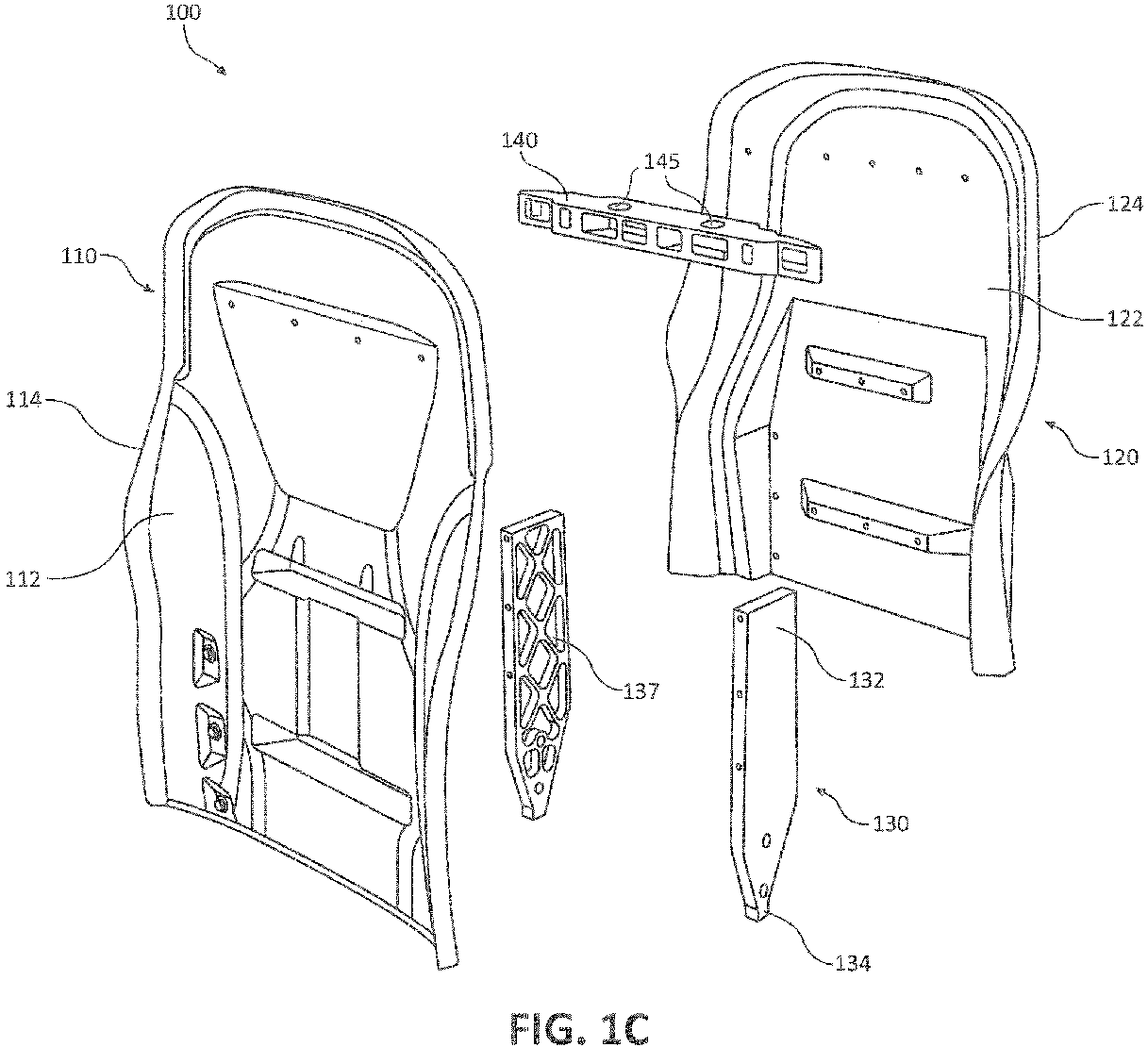
FIG. 1C illustrates an exploded perspective view of a modular monocoque backrest, in accordance with various embodiments; -
FIG. 2A illustrates a back perspective view of a modular monocoque backrest further comprising a restraint system, in accordance with various embodiments; -
FIG. 2B illustrates a front perspective view of a back shroud of a modular monocoque backrest further comprising a restraint system, in accordance with various embodiments; and -
FIG. 3 illustrates a front perspective view of a modular monocoque backrest further comprising a lumbar support mechanism, in accordance with various embodiments. - Elements and steps in the figures are illustrated for simplicity and clarity and have not necessarily been rendered according to any particular sequence. For example, steps that may be performed concurrently or in different order are illustrated in the figures to help to improve understanding of embodiments of the present disclosure.
- The detailed description of exemplary embodiments herein makes reference to the accompanying drawings, which show exemplary embodiments by way of illustration. While these exemplary embodiments are described in sufficient detail to enable those skilled in the art to practice the disclosures, it should be understood that other embodiments may be realized and that logical changes and adaptations in design and construction may be made in accordance with this disclosure and the teachings herein. Thus, the detailed description herein is presented for purposes of illustration only and not of limitation.
- The scope of the disclosure is defined by the appended claims and their legal equivalents rather than by merely the examples described. For example, the steps recited in any of the method or process descriptions may be executed in any order and are not necessarily limited to the order presented. Furthermore, any reference to singular includes plural embodiments, and any reference to more than one component or step may include a singular embodiment or step. Also, any reference to attached, fixed, coupled, connected or the like may include permanent, removable, temporary, partial, full and/or any other possible attachment option. Additionally, any reference to without contact (or similar phrases) may also include reduced contact or minimal contact. Surface shading lines may be used throughout the figures to denote different parts but not necessarily to denote the same or different materials.
- In various embodiments, and with reference to
FIGs. 1A ,1B , and1C , amodular monocoque backrest 100 is disclosed.Modular monocoque backrest 100 may be configured to provide a structure that is lighter in weight than conventional backrest structures, while also maintaining resistance to dynamic crash loads. Moreover,modular monocoque backrest 100 may also allow for exterior styling and decorative features without the need for additional exterior shrouding parts. In various embodiments,modular monocoque backrest 100 may comprise any suitable lightweight and structurally durable material. In this regard,modular monocoque backrest 100 may comprise a carbon fiber composite.Modular monocoque backrest 100 may also comprise a composite reinforcement material such as fiberglass and/or phenolic.Modular monocoque backrest 100 may be fabricated using any suitable carbon fiber manufacturing technique. For example,modular monocoque backrest 100 may be fabricated using a carbon fiber layup method, and molded into any desired shape and/or size. Any suitable layup method may be used to fabricatemodular monocoque backrest 100.Modular monocoque backrest 100 may also comprise any suitable coating and/or cover. For example,modular monocoque backrest 100 may be wrapped in leather, and/or any other suitable material, as desired. - In various embodiments, the use of a carbon fiber composite molded design may enable
modular monocoque backrest 100 to distribute and support stress loads through the external body ofmodular monocoque backrest 100, without the need for additional metallic components for reinforcement. Moreover, a carbon fiber composite molded design may also enablemodular monocoque backrest 100 to modularly incorporate additional design features into the molded design, eliminating the need for additional external mounting brackets, hardware, and/or the like. For example,modular monocoque backrest 100 may be molded to comprise a back literature pocket.Modular monocoque backrest 100 may also be molded to further comprise mounting brackets for a back literature pocket, and the back literature pocket may be fastened on.Modular monocoque backrest 100 may also be molded to comprise mounting provisions for speakers, lights, heating and/or cooling elements, arm rests, and/or any other suitable accessory. The use of a carbon fiber composite molded design may also enablemodular monocoque backrest 100 to mold into any desired shape and/or size. Desired exterior styling and designs may therefore be incorporated without the need for extra exterior shrouding parts. - In various embodiments,
modular monocoque backrest 100 may further distribute and support stress loads by incorporating support materials. In this regard, support materials may be added to the interior ofmodular monocoque backrest 100, in a position inward from the outer surfaces. For example,modular monocoque backrest 100 may comprise a support material in the interior having a honeycomb structure. The honeycomb structure may comprise a carbon fiber material, and/or any other suitable material cable of providing further support tomodular monocoque backrest 100. The honeycomb structure may comprise a separate object frommodular monocoque backrest 100, or the honeycomb structure may also integrate withmodular monocoque backrest 100. In various embodiments, a foam core may also be implemented in the interior ofmodular monocoque backrest 100. The foam core may be configured to further distribute and support stress loads. - In various embodiments,
modular monocoque backrest 100 may comprise afront shroud 110, aback shroud 120, and aback spar 130.Front shroud 110 may be configured to provide structural support tomodular monocoque backrest 100. Referring toFIG. 1C ,front shroud 110 may comprise acushion support surface 112 and a connectingsurface 114.Cushion support surface 112 may comprise an outer surface ofmodular monocoque backrest 100 afterfront shroud 110 is coupled to backshroud 120.Cushion support surface 112 may be configured to couple to a cushion, pad, and/or the like. Connectingsurface 114 may comprise an inner surface ofmodular monocoque backrest 100 afterfront shroud 110 is coupled to backshroud 120. In this regard, connectingsurface 114 may be configured as the surface offront shroud 110 that couples to backshroud 120. - In various embodiments,
back shroud 120 may be configured to provide further structural support tomodular monocoque backrest 100.Back shroud 120 may comprise a connectingsurface 122 and aback surface 124. Connectingsurface 122 may comprise an inner surface ofmodular monocoque backrest 100 afterfront shroud 110 is coupled to backshroud 120. In this regard, connectingsurface 122 may be configured as the surface ofback shroud 120 that couples tofront shroud 110. Back surface 124 may comprise an outer surface ofmodular monocoque backrest 100 afterfront shroud 110 is coupled to backshroud 120. - In various embodiments,
front shroud 110 may be configured to couple toback shroud 120. In this regard, connectingsurface 114 offront shroud 110 may be configured to couple to connectingsurface 122 ofback shroud 120.Front shroud 110 may be coupled toback shroud 120 using any suitable technique. For example,front shroud 110 may couple to backshroud 120 using an adhesive and/or bonding agent, such as an epoxy used for composite bonding, a resin, a thermoset, and/or a thermoplastic.Front shroud 110 may also couple to backshroud 120 using a mechanical fastener, such as a rivet, screw, and/or the like. Mechanical fasteners may be used at various intervals around the perimeter ofmodular monocoque backrest 100 to ensure a secure coupling betweenfront shroud 110 andback shroud 120. For example, mechanical fasteners may be used at about every one inch (25.4 mm), two inches (50.8 mm), and/or any other suitable and/or desired interval. In various embodiments,front shroud 110 may be coupled toback shroud 120 using a combination of coupling techniques, such as, for example, through the use of both an adhesive and a mechanical fastener. - In various embodiments, back
spar 130 may provide a mounting point to mountmodular monocoque backrest 100 to a surface, such as an aircraft floor, for example. Back spar 130 may also provide additional structural support formodular monocoque backrest 100 against torsional loads, inflight abuse loads, and/or crash loads. Back spar 130 may protrude downward fromfront shroud 110 andback shroud 120. In various embodiments,modular monocoque backrest 100 may comprise a plurality of back spars 130. Back spar 130 may comprise any suitable material. For example, backspar 130 may comprise a metal material, such as aluminum. In various embodiments, backspar 130 may also comprise a carbon fiber material. Back spar 130 may be molded intofront shroud 110 and/or backshroud 120, such thatback spar 130 andfront shroud 110 and/or backshroud 120 may form a single continuous part. In this regard, backspar 130,front shroud 110, and backshroud 120 may form an integral component inmodular monocoque backrest 100. - In various embodiments, back
spar 130 may comprise atop end 132 opposite of abottom end 134.Top end 132 may comprise the end ofback spar 130 proximate tomodular monocoque backrest 100, andbottom end 134 may comprise the end ofback spar 130 located furthest away frommodular monocoque backrest 100.Top end 132 may be configured to couple back spar 130 tomodular monocoque backrest 100.Top end 132 may be configured to couple tofront shroud 110 and/or backshroud 120.Top end 132 may be coupled tofront shroud 110 andback shroud 120 using any suitable method, such as via a mechanical fastener.Top end 132 may be inserted between the coupling offront shroud 110 andback shroud 120, and couple at a first edge to connectingsurface 114 offront shroud 110 and at a second edge to connectingsurface 122 ofback shroud 120.Bottom end 134 may comprise the mounting point forback spar 130, and may be configured to mount to a surface, such as an aircraft floor for example. Back spar 130 may also comprise a plurality ofcross bracings 137, configured to provide additional structural support tomodular monocoque backrest 100.Cross bracings 137 may comprise a plurality of voids on the inner surface ofback spar 130, configured to increase the structural strength ofback spar 130. In this regard, the use ofcross bracings 137 may also allow for a lighter weight backspar 130. - In various embodiments,
modular monocoque backrest 100 may also comprise aheadrest bracket 140.Headrest bracket 140 may be configured to receive a headrest (e.g., through headrest support holes 270, as depicted inFIG. 2A ) and provide structural support for the headrest. In this regard,headrest bracket 140 may comprise a plurality ofvoids 145 configured to receive and secure a headrest.Headrest bracket 140 may comprise any suitable material. For example,headrest bracket 140 may comprise an aluminum material.Headrest bracket 140 may be coupled to connectingsurface 114 offront shroud 110 and connectingsurface 122 ofback shroud 120, such thatheadrest bracket 140 may fit between the coupling offront shroud 110 to backshroud 120. In various embodiments,headrest bracket 140 may also comprise a carbon fiber material. Headrest bracket may be molded directly withback shroud 120, such thatback shroud 120 andheadrest bracket 140 may comprise a single continuous part. In this regard,headrest bracket 140,front shroud 110, and backshroud 120 may form an integral component inmodular monocoque backrest 100. - In various embodiments, and with reference to
FIGs. 2A and 2B , amodular monocoque backrest 200 further comprising restraint devices is disclosed. In this regard,modular monocoque backrest 200 may comprise a variety of restraint and safety devices and/or mechanisms. In various embodiments, arestraint inertia reel 250 may be configured to deploy and retract ashoulder restraint belt 255.Restraint inertia reel 250 may comprise a spring-loaded reel capable of deploying and retractingshoulder restraint belt 255.Restraint inertia reel 250 may also comprise an inertial locking mechanism, or other such similar apparatus and/or mechanism, capable of preventingshoulder restraint belt 255 from deploying further during a sudden acceleration.Restraint inertia reel 250 may be coupled to connectingsurface 122 ofback shroud 120.Restraint inertia reel 250 may be coupled to connectingsurface 122 ofback shroud 120 using a mounting bracket, bolt, and/or the like. In various embodiments, connectingsurface 122 ofback shroud 120 may be molded to comprise a mounting bracket forrestraint inertia reel 250. In that regard,restraint inertia reel 250 may bolt on to connectingsurface 122 without the need for additional hardware and/or mounting brackets. - In various embodiments,
shoulder restraint belt 255 may deploy fromrestraint inertia reel 250 through arestraint exit 260.Shoulder restraint belt 255 may then be configured to connect to a female safety attachment member, such as restraint buckle and/or the like, located on a seat.Restraint exit 260 may comprise any suitable material, such as aluminum. In various embodiments,restraint exit 260 may also comprise a carbon fiber material. In this regard,restraint exit 260 may be molded directly intoback shroud 120, such thatback shroud 120 andrestraint exit 260 comprise a single continuous part.Restraint exit 260 may comprise arestraint support 268 and arestraint bezel 264.Restraint support 268 may be configured to structurally guide and supportshoulder restraint belt 255 while deployed.Restraint support 268 may be coupled to the top ofback shroud 120. In this regard,back shroud 120 may be molded to comprise a void andrestraint support 268 may substantially align with the void to allowshoulder restraint belt 255 to pass through the top ofback shroud 120.Restraint bezel 264 may be configured to protectrestraint support 268 and to provide structural support forshoulder restraint belt 255 aftershoulder restraint belt 255 is deployed.Restraint bezel 264 may also be decorative in nature, comprising a metal plating and/or the like. - In various embodiments, and with reference to
FIG. 3 , amodular monocoque backrest 300 further comprising alumbar support mechanism 380 is depicted.Lumbar support mechanism 380 may be coupled to cushionsupport surface 112 offront shroud 110.Lumbar support mechanism 380 may be located in any suitable location oncushion support surface 112, such as, for example, in the general lumbar region ofcushion support surface 112.Lumbar support mechanism 380 may couple to cushionsupport surface 112 using any suitable technique, such as via a mounting bracket, fastener, bolt, and/or the like. In various embodiments,cushion support surface 112 may also be molded to comprise mounting brackets, and/or the like, enablinglumbar support mechanism 380 to couple to cushionsupport surface 112 without the need of additional hardware and/or mounting brackets. - In various embodiments,
lumbar support mechanism 380 may be configured to adjustably vary the amount of lumbar support inmodular monocoque backrest 300. For example,lumbar support mechanism 380 may adjust to protrude outward fromfront shroud 110. The outward protrusion may provide a passenger with greater support and comfort in the lumbar region. In various embodiments comprising a cushion coupled to the surface ofcushion support surface 112, the adjustedlumbar support mechanism 380 may protrude outward causing a curvature of the cushion in the lumbar area.Lumbar support mechanism 380 may also comprise a mechanical and/or electrical device allowing for adjustment to the level of outward protrusion. In this regard,lumbar support mechanism 380 may allow for a change in the protrusion amount to vary the distancelumbar support mechanism 380 is protruding away fromfront shroud 110.Lumbar support mechanism 380 may be adjusted using any suitable device, such as, for example, through electronic controls, mechanical controls, and/or the like. - Benefits, other advantages, and solutions to problems have been described herein with regard to specific embodiments. Furthermore, the connecting lines shown in the various figures contained herein are intended to represent exemplary functional relationships and/or physical couplings between the various elements. It should be noted that many alternative or additional functional relationships or physical connections may be present in a practical system. However, the benefits, advantages, solutions to problems, and any elements that may cause any benefit, advantage, or solution to occur or become more pronounced are not to be construed as critical, required, or essential features or elements of the disclosures. The scope of the disclosures is accordingly to be limited by nothing other than the appended claims and their legal equivalents, in which reference to an element in the singular is not intended to mean "one and only one" unless explicitly so stated, but rather "one or more." Moreover, where a phrase similar to "at least one of A, B, or C" is used in the claims, it is intended that the phrase be interpreted to mean that A alone may be present in an embodiment, B alone may be present in an embodiment, C alone may be present in an embodiment, or that any combination of the elements A, B and C may be present in a single embodiment; for example, A and B, A and C, B and C, or A and B and C.
- Systems, methods and apparatus are provided herein. In the detailed description herein, references to "various embodiments", "one embodiment", "an embodiment", "an example embodiment", etc., indicate that the embodiment described may include a particular feature, structure, or characteristic, but every embodiment may not necessarily include the particular feature, structure, or characteristic. Moreover, such phrases are not necessarily referring to the same embodiment. Further, when a particular feature, structure, or characteristic is described in connection with an embodiment, it is submitted that it is within the knowledge of one skilled in the art to affect such feature, structure, or characteristic in connection with other embodiments whether or not explicitly described. After reading the description, it will be apparent to one skilled in the relevant art(s) how to implement the disclosure in alternative embodiments.
- As used herein, the terms "comprises", "comprising", or any other variation thereof, are intended to cover a non-exclusive inclusion, such that a process, method, article, or apparatus that comprises a list of elements does not include only those elements but may include other elements not expressly listed or inherent to such process, method, article, or apparatus.
Claims (15)
- A seat backrest (100; 200; 300), comprising:a front shroud (110) formed from a first molded carbon fiber composite;a back shroud (120) coupled to the front shroud (110) and formed from a second molded carbon fiber composite; andan at least one back spar (130) coupled between the front shroud (110) and the back shroud (120), wherein the at least one back spar (130) extends in a direction away from the front shroud (110) and the back shroud (120).
- The seat backrest of claim 1, further comprising a headrest bracket (140) coupled at a first end to the back shroud (120) and coupled at a second end to the front shroud (110).
- The seat backrest of claim 1 or 2, further comprising a lumbar support mechanism (380) coupled to the front shroud (110).
- The seat backrest of any preceding claim, further comprising a restraint exit (260) coupled to the back shroud (120), wherein the restraint exit (260) defines a void on the back shroud (120), and wherein the void is configured to allow passage of a shoulder restraint belt (255).
- The seat backrest of claim 4, further comprising a restraint inertia reel (250) coupled to the back shroud (120), wherein the restraint inertia reel (250) is configured to deploy and retract the shoulder restraint belt (255) through the restraint exit (260); and/or
wherein the restraint exit (260) comprises a restraint support (268) having a top surface opposite of a bottom surface, wherein the bottom surface is coupled to the back shroud (120), and wherein a restraint bezel (264) is coupled to the top surface; and/or wherein the restraint exit comprises the second carbon fiber composite material, and wherein the restraint exit (260) is molded with the back shroud (120) such that the back shroud (120) and the restraint exit (260) comprise a single continuous part. - A modular monocoque backrest (100; 200; 300), comprising:a front shroud (110) having a cushion support surface (112) opposite of a first connecting surface (114), wherein the front shroud (110) comprises a first carbon fiber composite material;a back shroud (120) having a second connecting surface (122) opposite of a back surface (124), wherein the back shroud (120) comprises a second carbon fiber composite material, and wherein the second connecting surface (122) of the back shroud (120) is integrally coupled to the first connecting surface (112) of the front shroud (110) such that the front shroud (110) and the back shroud (120) form a single integrated object; andan at least one back spar (130) having a top end (132) opposite of a bottom end (134), wherein the top end (132) is coupled at a first edge to the first connecting surface (112) of the front shroud (110) and coupled at a second edge to the second connecting surface (122) of the back shroud (120), and wherein the bottom end (134) extends in a direction away from the front shroud (110) and the back shroud (120).
- The modular monocoque backrest of claim 6, further comprising a headrest bracket (140) coupled at a first end to the second connecting surface (122) of the back shroud and coupled at a second end to the first connecting surface of the front shroud.
- The modular monocoque backrest of claim 6 or 7, further comprising a lumbar support mechanism (380) coupled to the cushion support surface (112) of the front shroud (110).
- The modular monocoque backrest of claim 6, 7 or 8, further comprising a restraint exit (260) coupled to a top of the back shroud (120), wherein the restraint exit (260) defines a void on the top of the back shroud (120), configured to allow passage of a shoulder restraint belt (255).
- The modular monocoque backrest of claim 9, further comprising a restraint inertia reel (250) coupled to the second connecting surface (122) of the back shroud (120), wherein the restraint inertia reel (250) is configured to deploy and retract the shoulder restraint belt (255) through the restraint exit (260).
- The modular monocoque backrest of claim 9 or 10, wherein the restraint exit (260) comprises a restraint support (268) coupled to the top of the back shroud (120), and a restraint bezel (264) coupled to the top of the restraint support (268); and/or
wherein the restraint exit (260) comprises the second carbon fiber composite material, and wherein the restraint exit (260) is molded with the back shroud (120) such that the back shroud (120) and the restraint exit (260) comprise a single continuous part. - The seat back rest or modular monocoque backrest of any preceding claim, wherein the at least one back spar (130) comprises an aluminum material.
- The seat back rest or modular monocoque backrest of any preceding claim, wherein the at least one back spar (130) comprises a plurality of cross bracings (137).
- A method of manufacturing a modular monocoque backrest (100; 200; 300), comprising:forming a front shroud (110) having a cushion support surface (112) opposite of a first connecting surface (114), wherein the front shroud (110) comprises a first carbon fiber composite material;forming a back shroud (120) having a second connecting surface (122) opposite of a back surface (124), wherein the back shroud (120) comprises a second carbon fiber composite material;coupling the first connecting surface (112) of the front shroud (110) to the second connecting surface (122) of the back shroud (120); andcoupling an at least one back spar (130) to the front shroud (110) and the back shroud (120), wherein the back shroud (120) comprise a top end (132) opposite of a bottom end (134), wherein the top end (132) is configured to couple at a first edge to the first connecting surface (112) of the front shroud (110) and couple at a second edge to the second connecting surface (122) of the back shroud (120), and wherein the bottom end (134) extends in a direction away from the front shroud (110) and the back shroud (120).
- The method of claim 14, wherein the front shroud (110) is coupled to the back shroud (120) via an epoxy adhesive.
Applications Claiming Priority (1)
| Application Number | Priority Date | Filing Date | Title |
|---|---|---|---|
| US15/074,797 US9868374B2 (en) | 2016-03-18 | 2016-03-18 | Modular monocoque backrest |
Publications (2)
| Publication Number | Publication Date |
|---|---|
| EP3219616A1 true EP3219616A1 (en) | 2017-09-20 |
| EP3219616B1 EP3219616B1 (en) | 2020-05-13 |
Family
ID=58261567
Family Applications (1)
| Application Number | Title | Priority Date | Filing Date |
|---|---|---|---|
| EP17159520.0A Active EP3219616B1 (en) | 2016-03-18 | 2017-03-07 | Modular monocoque backrest |
Country Status (5)
| Country | Link |
|---|---|
| US (2) | US9868374B2 (en) |
| EP (1) | EP3219616B1 (en) |
| CN (1) | CN107200134B (en) |
| BR (1) | BR102017004946B1 (en) |
| CA (1) | CA2956758C (en) |
Cited By (1)
| Publication number | Priority date | Publication date | Assignee | Title |
|---|---|---|---|---|
| EP3718894A1 (en) * | 2019-04-01 | 2020-10-07 | Acro Aircraft Seating Limited | Seat back |
Families Citing this family (11)
| Publication number | Priority date | Publication date | Assignee | Title |
|---|---|---|---|---|
| EP3154818B1 (en) | 2014-06-10 | 2025-10-22 | Safran Seats USA LLC | Monocoque and semi-monocoque passenger seats with ergonomic design |
| US10966527B2 (en) | 2017-06-09 | 2021-04-06 | Steelcase Inc. | Seating arrangement and method of construction |
| US10194750B2 (en) * | 2015-04-13 | 2019-02-05 | Steelcase Inc. | Seating arrangement |
| JP6245300B2 (en) * | 2016-04-28 | 2017-12-13 | マツダ株式会社 | Seat back structure |
| USD825072S1 (en) * | 2016-12-06 | 2018-08-07 | The Raymond Corporation | Adjustable back pad |
| US10569680B2 (en) * | 2018-04-24 | 2020-02-25 | Lear Corporation | Seat assembly with adhered brackets |
| US10967772B2 (en) * | 2019-01-23 | 2021-04-06 | Volvo Car Corporation | Vehicle seat cushion carrier assembly for modular vehicle seat or the like |
| CN112406652B (en) * | 2019-08-20 | 2023-09-29 | 安道拓工程技术知识产权有限公司 | Backboard mounting structure of seat backrest and seat for vehicle |
| CN112369854A (en) * | 2020-11-30 | 2021-02-19 | 上海晋飞碳纤科技股份有限公司 | Connecting structure of composite material chair back and manufacturing method |
| JP7815705B2 (en) * | 2021-11-18 | 2026-02-18 | トヨタ紡織株式会社 | seat back |
| WO2024055021A1 (en) * | 2022-09-08 | 2024-03-14 | Anthro Form, Llc | Chair having interchangeable decorative feature |
Citations (10)
| Publication number | Priority date | Publication date | Assignee | Title |
|---|---|---|---|---|
| DE19757060A1 (en) * | 1997-12-20 | 1999-06-24 | Bayerische Motoren Werke Ag | Back rest for vehicle |
| US5988757A (en) * | 1996-08-29 | 1999-11-23 | Lear Corporation | Vehicle seat assembly |
| EP0972673A2 (en) * | 1998-06-20 | 2000-01-19 | Bayerische Motoren Werke Aktiengesellschaft, Patentabteilung AJ-3 | Motor vehicle seat |
| US20060061202A1 (en) * | 2004-09-17 | 2006-03-23 | B/E Aerospace, Inc. | Adjustable seat belt guide assembly |
| US20060152062A1 (en) * | 2004-12-20 | 2006-07-13 | Baultar I.D. Inc. | Adjustable ergonomic back for a seat |
| US20070138855A1 (en) * | 2005-12-15 | 2007-06-21 | Recaro Gmbh & Co. Kg | Vehicle seat, in particular a sports seat |
| US20090045658A1 (en) * | 2004-09-27 | 2009-02-19 | Mladen Humer | Vehicle seat having active head restraint system |
| DE102013225477A1 (en) * | 2013-08-30 | 2015-03-05 | Johnson Controls Gmbh | SEATBED FOR A VEHICLE SEAT AND VEHICLE SEAT |
| DE102013225963A1 (en) * | 2013-12-13 | 2015-06-18 | Johnson Controls Gmbh | Seat part and vehicle seat |
| US20160009209A1 (en) * | 2013-02-18 | 2016-01-14 | Faurecia Automotive Seating, Llc | Seat back for vehicle seat |
Family Cites Families (34)
| Publication number | Priority date | Publication date | Assignee | Title |
|---|---|---|---|---|
| US3695696A (en) * | 1970-01-19 | 1972-10-03 | Allied Chem | Vehicle seat with integral seat and back portions |
| US3873155A (en) * | 1972-03-07 | 1975-03-25 | American Seating Co | Transit seat with contoured plastic shell |
| US3861747A (en) * | 1972-12-11 | 1975-01-21 | Norman Diamond | Modular seat for public use |
| FR2274553A1 (en) * | 1974-06-14 | 1976-01-09 | Faure Bertrand | CUSHION CONSISTS OF A PADDING IN AT LEAST TWO PARTS GATHERED BACK TO BACK |
| US4108492A (en) * | 1974-10-18 | 1978-08-22 | Kirby Billy E | Back support |
| US4123105A (en) * | 1975-10-29 | 1978-10-31 | Interroyal Corporation | Chair construction |
| US4133579A (en) * | 1977-08-29 | 1979-01-09 | American Desk Manufacturing Co. | Stadium, gymnasium or like chair |
| DE3222951C2 (en) * | 1982-06-18 | 1985-10-24 | Keiper Recaro GmbH & Co, 7312 Kirchheim | Backrest for a vehicle seat, in particular a motor vehicle seat |
| US4722569A (en) * | 1985-09-13 | 1988-02-02 | Robin L. Morgenstern | Power and manually actuated lumbosacral backrest |
| JPH057957Y2 (en) * | 1988-11-09 | 1993-03-01 | ||
| US5318346A (en) * | 1991-05-30 | 1994-06-07 | Steelcase Inc. | Chair with zero front rise control |
| US5451071A (en) * | 1993-09-16 | 1995-09-19 | Cannondale Corporation | Bicycle frame |
| US5582459A (en) * | 1993-09-30 | 1996-12-10 | Itoki Crebio Corporation | Chair having tiltable seat back |
| WO1996041556A1 (en) * | 1995-06-09 | 1996-12-27 | Herman Miller, Inc. | Office chair and adjustable lumbar support therefor |
| US5988748A (en) * | 1995-11-27 | 1999-11-23 | Lear Corporation | Automotive seat bottom assembly |
| US5879055A (en) * | 1996-09-24 | 1999-03-09 | Lear Corporation | Automative seat back panel |
| US5895096A (en) * | 1997-04-10 | 1999-04-20 | Lear Corporation | Vehicle seat back assembly and method of making a vehicle seat back assembly |
| US6189972B1 (en) * | 1998-06-05 | 2001-02-20 | Teknion Furniture Systems Inc. | Lumbar support adjustment mechanism |
| US6378942B1 (en) * | 2000-06-20 | 2002-04-30 | Global Total Office | Backrest with adjustable lumbar support |
| US6557307B2 (en) * | 2001-06-11 | 2003-05-06 | Haworth, Inc. | Upright panel with height adjustable back cushion |
| ES1049384Y (en) * | 2001-06-12 | 2002-09-01 | Figueras Int Seating Sa | BACKUP FOR PERFECTED ARMCHAIRS. |
| JP4737501B2 (en) * | 2004-10-28 | 2011-08-03 | テイ・エス テック株式会社 | Vehicle seat |
| US8235467B2 (en) * | 2006-04-27 | 2012-08-07 | Ts Tech Co., Ltd. | Vehicle seat |
| US7954762B2 (en) | 2006-05-17 | 2011-06-07 | The Boeing Company | Lightweight aircraft passenger seat with composite construction |
| US8052213B2 (en) * | 2006-07-03 | 2011-11-08 | Milsco Manufacturing Company, A Unit Of Jason Incorporated | Seat with adjustable seat occupant support assembly and integrally formed seat shell therefor |
| US8366044B2 (en) * | 2009-10-09 | 2013-02-05 | PAC Seating Systems, Inc. | Removable back shell for an aircraft seat |
| JP5511310B2 (en) * | 2009-10-27 | 2014-06-04 | 日本発條株式会社 | Vehicle seat |
| WO2012169906A1 (en) * | 2011-06-07 | 2012-12-13 | Composite Helicopter Holdings Limited | A helicopter |
| USD697726S1 (en) * | 2012-09-20 | 2014-01-21 | Steelcase Inc. | Chair |
| US9415713B2 (en) * | 2013-01-24 | 2016-08-16 | Ford Global Technologies, Llc | Flexible seatback system |
| US8960791B2 (en) * | 2013-07-02 | 2015-02-24 | Ford Global Technologies, Llc | Trim attachment apparatus for vehicle seating assembly |
| US9649963B2 (en) * | 2014-03-04 | 2017-05-16 | Ford Global Technologies, Pllc | Trim and foam assembly for a vehicle seat |
| EP3154818B1 (en) | 2014-06-10 | 2025-10-22 | Safran Seats USA LLC | Monocoque and semi-monocoque passenger seats with ergonomic design |
| US20170210263A1 (en) * | 2016-01-25 | 2017-07-27 | Ford Global Technologies, Llc | Integrated independent thigh supports |
-
2016
- 2016-03-18 US US15/074,797 patent/US9868374B2/en active Active
-
2017
- 2017-01-30 CA CA2956758A patent/CA2956758C/en active Active
- 2017-03-07 EP EP17159520.0A patent/EP3219616B1/en active Active
- 2017-03-13 BR BR102017004946-9A patent/BR102017004946B1/en active IP Right Grant
- 2017-03-17 CN CN201710160771.0A patent/CN107200134B/en active Active
- 2017-12-08 US US15/836,412 patent/US10071661B2/en active Active
Patent Citations (10)
| Publication number | Priority date | Publication date | Assignee | Title |
|---|---|---|---|---|
| US5988757A (en) * | 1996-08-29 | 1999-11-23 | Lear Corporation | Vehicle seat assembly |
| DE19757060A1 (en) * | 1997-12-20 | 1999-06-24 | Bayerische Motoren Werke Ag | Back rest for vehicle |
| EP0972673A2 (en) * | 1998-06-20 | 2000-01-19 | Bayerische Motoren Werke Aktiengesellschaft, Patentabteilung AJ-3 | Motor vehicle seat |
| US20060061202A1 (en) * | 2004-09-17 | 2006-03-23 | B/E Aerospace, Inc. | Adjustable seat belt guide assembly |
| US20090045658A1 (en) * | 2004-09-27 | 2009-02-19 | Mladen Humer | Vehicle seat having active head restraint system |
| US20060152062A1 (en) * | 2004-12-20 | 2006-07-13 | Baultar I.D. Inc. | Adjustable ergonomic back for a seat |
| US20070138855A1 (en) * | 2005-12-15 | 2007-06-21 | Recaro Gmbh & Co. Kg | Vehicle seat, in particular a sports seat |
| US20160009209A1 (en) * | 2013-02-18 | 2016-01-14 | Faurecia Automotive Seating, Llc | Seat back for vehicle seat |
| DE102013225477A1 (en) * | 2013-08-30 | 2015-03-05 | Johnson Controls Gmbh | SEATBED FOR A VEHICLE SEAT AND VEHICLE SEAT |
| DE102013225963A1 (en) * | 2013-12-13 | 2015-06-18 | Johnson Controls Gmbh | Seat part and vehicle seat |
Cited By (1)
| Publication number | Priority date | Publication date | Assignee | Title |
|---|---|---|---|---|
| EP3718894A1 (en) * | 2019-04-01 | 2020-10-07 | Acro Aircraft Seating Limited | Seat back |
Also Published As
| Publication number | Publication date |
|---|---|
| US20180099597A1 (en) | 2018-04-12 |
| CA2956758A1 (en) | 2017-09-18 |
| US9868374B2 (en) | 2018-01-16 |
| CA2956758C (en) | 2025-07-08 |
| BR102017004946B1 (en) | 2022-04-26 |
| CN107200134B (en) | 2021-07-13 |
| CN107200134A (en) | 2017-09-26 |
| US10071661B2 (en) | 2018-09-11 |
| US20170267146A1 (en) | 2017-09-21 |
| EP3219616B1 (en) | 2020-05-13 |
| BR102017004946A2 (en) | 2017-09-26 |
Similar Documents
| Publication | Publication Date | Title |
|---|---|---|
| US10071661B2 (en) | Modular monocoque backrest | |
| KR20120050922A (en) | Improvement of aircraft seats and related components | |
| EP3426556B1 (en) | Aircraft seat back with non-tubular perimeter flange | |
| US4498649A (en) | Aircraft seating | |
| US10543923B2 (en) | Seat backrest | |
| US12187174B2 (en) | Structural assembly for passenger seat and associated methods | |
| EP1714569A1 (en) | Bicycle helmet | |
| JP2014504981A (en) | Ultralight seat for aircraft | |
| EP3225552A1 (en) | Contoured stowable seat | |
| EP3718894B1 (en) | Seat back | |
| EP3733517A1 (en) | Composite seat assemblies including high performance fibers | |
| US20230025571A1 (en) | Aircraft seat device, aircraft seat, method for producing the aircraft seat device, and modular system | |
| US20210331609A1 (en) | Light weight metal back with extra living space | |
| US10807720B2 (en) | Detachable cabin attendant seat | |
| KR101771011B1 (en) | Hybrid type vehicle rear seat back frame | |
| EP3378771B1 (en) | Inertia reel interface for stowable seats | |
| JP6700887B2 (en) | Vehicle seat | |
| EP3107422B1 (en) | Seat for vehicles and manufacturing method thereof |
Legal Events
| Date | Code | Title | Description |
|---|---|---|---|
| PUAI | Public reference made under article 153(3) epc to a published international application that has entered the european phase |
Free format text: ORIGINAL CODE: 0009012 |
|
| STAA | Information on the status of an ep patent application or granted ep patent |
Free format text: STATUS: THE APPLICATION HAS BEEN PUBLISHED |
|
| AK | Designated contracting states |
Kind code of ref document: A1 Designated state(s): AL AT BE BG CH CY CZ DE DK EE ES FI FR GB GR HR HU IE IS IT LI LT LU LV MC MK MT NL NO PL PT RO RS SE SI SK SM TR |
|
| AX | Request for extension of the european patent |
Extension state: BA ME |
|
| STAA | Information on the status of an ep patent application or granted ep patent |
Free format text: STATUS: REQUEST FOR EXAMINATION WAS MADE |
|
| 17P | Request for examination filed |
Effective date: 20180320 |
|
| RBV | Designated contracting states (corrected) |
Designated state(s): AL AT BE BG CH CY CZ DE DK EE ES FI FR GB GR HR HU IE IS IT LI LT LU LV MC MK MT NL NO PL PT RO RS SE SI SK SM TR |
|
| STAA | Information on the status of an ep patent application or granted ep patent |
Free format text: STATUS: EXAMINATION IS IN PROGRESS |
|
| 17Q | First examination report despatched |
Effective date: 20190307 |
|
| GRAP | Despatch of communication of intention to grant a patent |
Free format text: ORIGINAL CODE: EPIDOSNIGR1 |
|
| STAA | Information on the status of an ep patent application or granted ep patent |
Free format text: STATUS: GRANT OF PATENT IS INTENDED |
|
| RIC1 | Information provided on ipc code assigned before grant |
Ipc: B60N 2/68 20060101ALI20191018BHEP Ipc: B64D 11/06 20060101AFI20191018BHEP Ipc: B60N 2/66 20060101ALI20191018BHEP |
|
| INTG | Intention to grant announced |
Effective date: 20191127 |
|
| RIN1 | Information on inventor provided before grant (corrected) |
Inventor name: HOOVER, DOUGLAS E. Inventor name: FERGUSON, KEITH M. |
|
| GRAS | Grant fee paid |
Free format text: ORIGINAL CODE: EPIDOSNIGR3 |
|
| GRAA | (expected) grant |
Free format text: ORIGINAL CODE: 0009210 |
|
| STAA | Information on the status of an ep patent application or granted ep patent |
Free format text: STATUS: THE PATENT HAS BEEN GRANTED |
|
| AK | Designated contracting states |
Kind code of ref document: B1 Designated state(s): AL AT BE BG CH CY CZ DE DK EE ES FI FR GB GR HR HU IE IS IT LI LT LU LV MC MK MT NL NO PL PT RO RS SE SI SK SM TR |
|
| REG | Reference to a national code |
Ref country code: GB Ref legal event code: FG4D |
|
| REG | Reference to a national code |
Ref country code: CH Ref legal event code: EP |
|
| REG | Reference to a national code |
Ref country code: DE Ref legal event code: R096 Ref document number: 602017016313 Country of ref document: DE |
|
| REG | Reference to a national code |
Ref country code: AT Ref legal event code: REF Ref document number: 1269949 Country of ref document: AT Kind code of ref document: T Effective date: 20200615 |
|
| REG | Reference to a national code |
Ref country code: LT Ref legal event code: MG4D |
|
| REG | Reference to a national code |
Ref country code: NL Ref legal event code: MP Effective date: 20200513 |
|
| PG25 | Lapsed in a contracting state [announced via postgrant information from national office to epo] |
Ref country code: SE Free format text: LAPSE BECAUSE OF FAILURE TO SUBMIT A TRANSLATION OF THE DESCRIPTION OR TO PAY THE FEE WITHIN THE PRESCRIBED TIME-LIMIT Effective date: 20200513 Ref country code: LT Free format text: LAPSE BECAUSE OF FAILURE TO SUBMIT A TRANSLATION OF THE DESCRIPTION OR TO PAY THE FEE WITHIN THE PRESCRIBED TIME-LIMIT Effective date: 20200513 Ref country code: PT Free format text: LAPSE BECAUSE OF FAILURE TO SUBMIT A TRANSLATION OF THE DESCRIPTION OR TO PAY THE FEE WITHIN THE PRESCRIBED TIME-LIMIT Effective date: 20200914 Ref country code: IS Free format text: LAPSE BECAUSE OF FAILURE TO SUBMIT A TRANSLATION OF THE DESCRIPTION OR TO PAY THE FEE WITHIN THE PRESCRIBED TIME-LIMIT Effective date: 20200913 Ref country code: NO Free format text: LAPSE BECAUSE OF FAILURE TO SUBMIT A TRANSLATION OF THE DESCRIPTION OR TO PAY THE FEE WITHIN THE PRESCRIBED TIME-LIMIT Effective date: 20200813 Ref country code: GR Free format text: LAPSE BECAUSE OF FAILURE TO SUBMIT A TRANSLATION OF THE DESCRIPTION OR TO PAY THE FEE WITHIN THE PRESCRIBED TIME-LIMIT Effective date: 20200814 Ref country code: FI Free format text: LAPSE BECAUSE OF FAILURE TO SUBMIT A TRANSLATION OF THE DESCRIPTION OR TO PAY THE FEE WITHIN THE PRESCRIBED TIME-LIMIT Effective date: 20200513 |
|
| PG25 | Lapsed in a contracting state [announced via postgrant information from national office to epo] |
Ref country code: LV Free format text: LAPSE BECAUSE OF FAILURE TO SUBMIT A TRANSLATION OF THE DESCRIPTION OR TO PAY THE FEE WITHIN THE PRESCRIBED TIME-LIMIT Effective date: 20200513 Ref country code: HR Free format text: LAPSE BECAUSE OF FAILURE TO SUBMIT A TRANSLATION OF THE DESCRIPTION OR TO PAY THE FEE WITHIN THE PRESCRIBED TIME-LIMIT Effective date: 20200513 Ref country code: BG Free format text: LAPSE BECAUSE OF FAILURE TO SUBMIT A TRANSLATION OF THE DESCRIPTION OR TO PAY THE FEE WITHIN THE PRESCRIBED TIME-LIMIT Effective date: 20200813 Ref country code: RS Free format text: LAPSE BECAUSE OF FAILURE TO SUBMIT A TRANSLATION OF THE DESCRIPTION OR TO PAY THE FEE WITHIN THE PRESCRIBED TIME-LIMIT Effective date: 20200513 |
|
| REG | Reference to a national code |
Ref country code: AT Ref legal event code: MK05 Ref document number: 1269949 Country of ref document: AT Kind code of ref document: T Effective date: 20200513 |
|
| PG25 | Lapsed in a contracting state [announced via postgrant information from national office to epo] |
Ref country code: AL Free format text: LAPSE BECAUSE OF FAILURE TO SUBMIT A TRANSLATION OF THE DESCRIPTION OR TO PAY THE FEE WITHIN THE PRESCRIBED TIME-LIMIT Effective date: 20200513 Ref country code: NL Free format text: LAPSE BECAUSE OF FAILURE TO SUBMIT A TRANSLATION OF THE DESCRIPTION OR TO PAY THE FEE WITHIN THE PRESCRIBED TIME-LIMIT Effective date: 20200513 |
|
| PG25 | Lapsed in a contracting state [announced via postgrant information from national office to epo] |
Ref country code: IT Free format text: LAPSE BECAUSE OF FAILURE TO SUBMIT A TRANSLATION OF THE DESCRIPTION OR TO PAY THE FEE WITHIN THE PRESCRIBED TIME-LIMIT Effective date: 20200513 Ref country code: RO Free format text: LAPSE BECAUSE OF FAILURE TO SUBMIT A TRANSLATION OF THE DESCRIPTION OR TO PAY THE FEE WITHIN THE PRESCRIBED TIME-LIMIT Effective date: 20200513 Ref country code: CZ Free format text: LAPSE BECAUSE OF FAILURE TO SUBMIT A TRANSLATION OF THE DESCRIPTION OR TO PAY THE FEE WITHIN THE PRESCRIBED TIME-LIMIT Effective date: 20200513 Ref country code: ES Free format text: LAPSE BECAUSE OF FAILURE TO SUBMIT A TRANSLATION OF THE DESCRIPTION OR TO PAY THE FEE WITHIN THE PRESCRIBED TIME-LIMIT Effective date: 20200513 Ref country code: AT Free format text: LAPSE BECAUSE OF FAILURE TO SUBMIT A TRANSLATION OF THE DESCRIPTION OR TO PAY THE FEE WITHIN THE PRESCRIBED TIME-LIMIT Effective date: 20200513 Ref country code: SM Free format text: LAPSE BECAUSE OF FAILURE TO SUBMIT A TRANSLATION OF THE DESCRIPTION OR TO PAY THE FEE WITHIN THE PRESCRIBED TIME-LIMIT Effective date: 20200513 Ref country code: EE Free format text: LAPSE BECAUSE OF FAILURE TO SUBMIT A TRANSLATION OF THE DESCRIPTION OR TO PAY THE FEE WITHIN THE PRESCRIBED TIME-LIMIT Effective date: 20200513 Ref country code: DK Free format text: LAPSE BECAUSE OF FAILURE TO SUBMIT A TRANSLATION OF THE DESCRIPTION OR TO PAY THE FEE WITHIN THE PRESCRIBED TIME-LIMIT Effective date: 20200513 |
|
| REG | Reference to a national code |
Ref country code: DE Ref legal event code: R097 Ref document number: 602017016313 Country of ref document: DE |
|
| PG25 | Lapsed in a contracting state [announced via postgrant information from national office to epo] |
Ref country code: SK Free format text: LAPSE BECAUSE OF FAILURE TO SUBMIT A TRANSLATION OF THE DESCRIPTION OR TO PAY THE FEE WITHIN THE PRESCRIBED TIME-LIMIT Effective date: 20200513 Ref country code: PL Free format text: LAPSE BECAUSE OF FAILURE TO SUBMIT A TRANSLATION OF THE DESCRIPTION OR TO PAY THE FEE WITHIN THE PRESCRIBED TIME-LIMIT Effective date: 20200513 |
|
| PLBE | No opposition filed within time limit |
Free format text: ORIGINAL CODE: 0009261 |
|
| STAA | Information on the status of an ep patent application or granted ep patent |
Free format text: STATUS: NO OPPOSITION FILED WITHIN TIME LIMIT |
|
| 26N | No opposition filed |
Effective date: 20210216 |
|
| PG25 | Lapsed in a contracting state [announced via postgrant information from national office to epo] |
Ref country code: SI Free format text: LAPSE BECAUSE OF FAILURE TO SUBMIT A TRANSLATION OF THE DESCRIPTION OR TO PAY THE FEE WITHIN THE PRESCRIBED TIME-LIMIT Effective date: 20200513 |
|
| REG | Reference to a national code |
Ref country code: DE Ref legal event code: R119 Ref document number: 602017016313 Country of ref document: DE |
|
| PG25 | Lapsed in a contracting state [announced via postgrant information from national office to epo] |
Ref country code: MC Free format text: LAPSE BECAUSE OF FAILURE TO SUBMIT A TRANSLATION OF THE DESCRIPTION OR TO PAY THE FEE WITHIN THE PRESCRIBED TIME-LIMIT Effective date: 20200513 |
|
| REG | Reference to a national code |
Ref country code: CH Ref legal event code: PL |
|
| REG | Reference to a national code |
Ref country code: BE Ref legal event code: MM Effective date: 20210331 |
|
| PG25 | Lapsed in a contracting state [announced via postgrant information from national office to epo] |
Ref country code: IE Free format text: LAPSE BECAUSE OF NON-PAYMENT OF DUE FEES Effective date: 20210307 Ref country code: DE Free format text: LAPSE BECAUSE OF NON-PAYMENT OF DUE FEES Effective date: 20211001 Ref country code: CH Free format text: LAPSE BECAUSE OF NON-PAYMENT OF DUE FEES Effective date: 20210331 Ref country code: LI Free format text: LAPSE BECAUSE OF NON-PAYMENT OF DUE FEES Effective date: 20210331 Ref country code: LU Free format text: LAPSE BECAUSE OF NON-PAYMENT OF DUE FEES Effective date: 20210307 |
|
| PG25 | Lapsed in a contracting state [announced via postgrant information from national office to epo] |
Ref country code: BE Free format text: LAPSE BECAUSE OF NON-PAYMENT OF DUE FEES Effective date: 20210331 |
|
| PG25 | Lapsed in a contracting state [announced via postgrant information from national office to epo] |
Ref country code: HU Free format text: LAPSE BECAUSE OF FAILURE TO SUBMIT A TRANSLATION OF THE DESCRIPTION OR TO PAY THE FEE WITHIN THE PRESCRIBED TIME-LIMIT; INVALID AB INITIO Effective date: 20170307 |
|
| P01 | Opt-out of the competence of the unified patent court (upc) registered |
Effective date: 20230521 |
|
| PG25 | Lapsed in a contracting state [announced via postgrant information from national office to epo] |
Ref country code: CY Free format text: LAPSE BECAUSE OF FAILURE TO SUBMIT A TRANSLATION OF THE DESCRIPTION OR TO PAY THE FEE WITHIN THE PRESCRIBED TIME-LIMIT Effective date: 20200513 |
|
| PG25 | Lapsed in a contracting state [announced via postgrant information from national office to epo] |
Ref country code: MK Free format text: LAPSE BECAUSE OF FAILURE TO SUBMIT A TRANSLATION OF THE DESCRIPTION OR TO PAY THE FEE WITHIN THE PRESCRIBED TIME-LIMIT Effective date: 20200513 |
|
| PG25 | Lapsed in a contracting state [announced via postgrant information from national office to epo] |
Ref country code: MT Free format text: LAPSE BECAUSE OF FAILURE TO SUBMIT A TRANSLATION OF THE DESCRIPTION OR TO PAY THE FEE WITHIN THE PRESCRIBED TIME-LIMIT Effective date: 20200513 |
|
| PG25 | Lapsed in a contracting state [announced via postgrant information from national office to epo] |
Ref country code: TR Free format text: LAPSE BECAUSE OF FAILURE TO SUBMIT A TRANSLATION OF THE DESCRIPTION OR TO PAY THE FEE WITHIN THE PRESCRIBED TIME-LIMIT Effective date: 20200513 |
|
| PGFP | Annual fee paid to national office [announced via postgrant information from national office to epo] |
Ref country code: GB Payment date: 20260220 Year of fee payment: 10 |
|
| PGFP | Annual fee paid to national office [announced via postgrant information from national office to epo] |
Ref country code: FR Payment date: 20260219 Year of fee payment: 10 |