EP3219609A1 - Propeller pitch change actuation system - Google Patents
Propeller pitch change actuation system Download PDFInfo
- Publication number
- EP3219609A1 EP3219609A1 EP17159888.1A EP17159888A EP3219609A1 EP 3219609 A1 EP3219609 A1 EP 3219609A1 EP 17159888 A EP17159888 A EP 17159888A EP 3219609 A1 EP3219609 A1 EP 3219609A1
- Authority
- EP
- European Patent Office
- Prior art keywords
- yoke plate
- aperture
- wear
- plate
- ear
- Prior art date
- Legal status (The legal status is an assumption and is not a legal conclusion. Google has not performed a legal analysis and makes no representation as to the accuracy of the status listed.)
- Granted
Links
Images

Classifications
-
- B—PERFORMING OPERATIONS; TRANSPORTING
- B64—AIRCRAFT; AVIATION; COSMONAUTICS
- B64C—AEROPLANES; HELICOPTERS
- B64C11/00—Propellers, e.g. of ducted type; Features common to propellers and rotors for rotorcraft
- B64C11/30—Blade pitch-changing mechanisms
- B64C11/32—Blade pitch-changing mechanisms mechanical
-
- B—PERFORMING OPERATIONS; TRANSPORTING
- B63—SHIPS OR OTHER WATERBORNE VESSELS; RELATED EQUIPMENT
- B63H—MARINE PROPULSION OR STEERING
- B63H3/00—Propeller-blade pitch changing
-
- B—PERFORMING OPERATIONS; TRANSPORTING
- B64—AIRCRAFT; AVIATION; COSMONAUTICS
- B64C—AEROPLANES; HELICOPTERS
- B64C11/00—Propellers, e.g. of ducted type; Features common to propellers and rotors for rotorcraft
- B64C11/30—Blade pitch-changing mechanisms
- B64C11/38—Blade pitch-changing mechanisms fluid, e.g. hydraulic
-
- B—PERFORMING OPERATIONS; TRANSPORTING
- B64—AIRCRAFT; AVIATION; COSMONAUTICS
- B64F—GROUND OR AIRCRAFT-CARRIER-DECK INSTALLATIONS SPECIALLY ADAPTED FOR USE IN CONNECTION WITH AIRCRAFT; DESIGNING, MANUFACTURING, ASSEMBLING, CLEANING, MAINTAINING OR REPAIRING AIRCRAFT, NOT OTHERWISE PROVIDED FOR; HANDLING, TRANSPORTING, TESTING OR INSPECTING AIRCRAFT COMPONENTS, NOT OTHERWISE PROVIDED FOR
- B64F5/00—Designing, manufacturing, assembling, cleaning, maintaining or repairing aircraft, not otherwise provided for; Handling, transporting, testing or inspecting aircraft components, not otherwise provided for
- B64F5/10—Manufacturing or assembling aircraft, e.g. jigs therefor
Definitions
- the present disclosure relates to propeller pitch change systems, and, more specifically, to a yoke plate arrangement for a propeller pitch change system.
- Propeller pitch change actuation systems for aircraft include propeller blades attached to trunnion bearings.
- the trunnion bearings are coupled between an aft yoke plate and a forward yoke plate.
- the yoke plates may be translated forward and aft to rotate the propeller blades and ultimately change their pitch angles. Due to blade loading, friction causing motion, vibrations, etc., the yoke plates may wear over time.
- a yoke plate having extensive wear may be replaced by removing the entire propeller pitch change actuation system from the aircraft to replace the yoke plate.
- a yoke plate arrangement may comprise a yoke plate, a wear plate comprising a wear surface and a contact surface, wherein a post extends from the contact surface, and a yoke plate ear extending from the yoke plate, wherein a first aperture is disposed in the yoke plate ear, the post located at least partially within the first aperture, the contact surface configured to be in contact with the yoke plate ear.
- the first aperture may extend in a first direction and the yoke plate ear may comprise a second aperture extending in a second direction, the second direction being substantially perpendicular to the first direction, wherein the first aperture and the second aperture align.
- the yoke plate arrangement may further comprise a retaining feature, the retaining feature located at least partially within the second aperture and configured to retain the post inside of the first aperture.
- the post may include a trench extending in the second direction, the retaining feature located at least partially in the trench.
- the post may include a retaining aperture, the retaining feature located at least partially in the retaining aperture.
- the retaining feature may comprise a pin.
- the retaining feature may further comprise a set-screw, the set-screw threadingly attached to the second aperture.
- the first direction may comprise an axial direction and the second direction may comprise a circumferential direction.
- the wear surface may be configured to contact a trunnion.
- An anti-rotation surface may be disposed on the yoke plate ear. The anti-rotation surface may be configured to engage the wear plate to prevent the wear plate from rotating with respect to the yoke plate ear.
- the anti-rotation surface may be configured to engage a radially inward surface of the wear plate.
- a propeller pitch change actuation system may comprise a propeller coupled to a trunnion, a forward yoke plate coupled to a shaft, the forward yoke plate comprising a forward yoke plate ear extending from the forward yoke plate, an aft yoke plate coupled to the shaft, the aft yoke plate comprising an aft yoke plate ear extending from the aft yoke plate, wherein a first aft aperture is disposed in the aft yoke plate ear, the first aperture extending in a first direction, the trunnion located between the forward yoke plate ear and the aft yoke plate ear, and an aft wear plate coupled to the aft yoke plate ear comprising a wear surface and a contact surface, wherein a post extends from the contact surface, the post located at least partially inside of the first aperture.
- the propeller pitch change actuation system may further comprise a forward wear plate coupled to the forward yoke plate ear.
- the wear surface may be in contact with the trunnion, the trunnion located between the aft wear plate and the forward wear plate.
- the contact surface may be in contact with the forward yoke plate ear.
- the propeller pitch change actuation system may further comprise a retaining feature configured to retain the post within the first aperture.
- a second aperture may be disposed in the aft yoke plate ear, the second aperture extending in a second direction, the retaining feature located at least partially within the second aperture.
- a method of installing a wear plate onto a yoke plate may comprise inserting a wear plate post into a first aperture disposed in the yoke plate, pushing the wear plate post into the first aperture until a contact surface of the wear plate makes contact with a yoke plate ear, inserting a pin into a second aperture disposed in the yoke plate, and attaching a set-screw to the yoke plate ear to retain the pin.
- the pin may be inserted into a trench located in the wear plate post in response to the inserting the pin into the second aperture.
- the pin may be inserted into a retaining aperture located in the wear plate post in response to the inserting the pin into the second aperture.
- references to "various embodiments”, “one embodiment” “an embodiment”, “an example embodiment”, etc. indicate that the embodiment described may include a particular feature, structure, or characteristic, but every embodiment may not necessarily include the particular feature, structure, or characteristic. Moreover, such phrases are not necessarily referring to the same embodiment. Further, when a particular feature, structure, or characteristic is described in connection with an embodiment, it is submitted that it is within the knowledge of one skilled in the art to affect such feature, structure, or characteristic in connection with other embodiments whether or not explicitly described. After reading the description, it will be apparent to one skilled in the relevant art(s) how to implement the disclosure in alternative embodiments.
- any reference to singular includes plural embodiments, and any reference to more than one component or step may include a singular embodiment or step.
- any reference to attached, fixed, connected or the like may include permanent, removable, temporary, partial, full and/or any other possible attachment option.
- any reference to without contact (or similar phrases) may also include reduced contact or minimal contact. Surface shading lines may be used throughout the figures to denote different parts but not necessarily to denote the same or different materials.
- tail refers to the direction associated with the tail (e.g., the back end) of an aircraft, or generally, to the direction of exhaust of the gas turbine.
- forward refers to the direction associated with the nose (e.g., the front end) of an aircraft, or generally, to the direction of flight or motion.
- a propeller pitch change actuation systems for aircraft include a propeller blade comprising a trunnion bearing, wherein the trunnion bearing is disposed between an aft yoke plate and a forward yoke plate.
- the yoke plates may be translated forward and aft to rotate the propeller, in a manner similar to a bell crank. Due to blade loads, which may be extremely high (i.e., in the thousands of pounds of force range), the yoke plates may wear over time. Thus, at various maintenance intervals, the entire propeller pitch change actuation system may be removed from the aircraft to replace the yoke plates.
- a replaceable wear plate is provided herein.
- the wear plate is removably coupled to a yoke plate.
- the wear plate acts as a sacrificial part to extend the life of the yoke plate and to simplify maintenance due to worn parts, among other benefits.
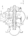
- a propeller pitch change actuation system 100 may include a forward yoke plate 134 and an aft yoke plate 132.
- Forward yoke plate 134 may be coupled to aft yoke plate 132.
- Forward yoke plate 134 may be coupled to shaft 130.
- Aft yoke plate 132 may be coupled to shaft 130.
- Forward yoke plate 134 and aft yoke plate 132 may be coupled to piston 128.
- Propeller pitch change actuation system 100 may include propeller blades 122.
- Propeller blades 122 may be coupled to trunnion 118.
- trunnion 118 may comprise a trunnion bearing.
- Forward yoke plate 134 and aft yoke plate 132 may be coupled to trunnion 118.
- trunnion 118 may be trapped between forward yoke plate 134 and aft yoke plate 132.
- Propeller blades 122 may rotate about rotation axis 120 in response to forward yoke plate 134 and aft yoke plate 132 moving forward and/or aft (i.e., along the z-axis).
- a wear plate (also referred to herein as an aft wear plate) 142 may be coupled to aft yoke plate 132.
- a wear plate (also referred to herein as a forward wear plate) 144 may be coupled to forward yoke plate 134.
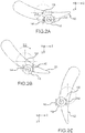
- trunnion 118 may travel in an arc-like motion about rotation axis 120. More particularly, trunnion 118 may travel in an arc about rotation axis 120 having a radius 204.
- Propeller blades 122 may rotate in a rotational direction 202, (a first rotational direction, or the clockwise direction as illustrated in FIG. 2B ) in response to wear plate 142 and wear plate 144 moving aft in the negative z-direction.
- Trunnion 118 may move relative to wear plate 142 and wear plate 144 in response to this motion.
- trunnion 118 is illustrated as having moved outboard (in the x-direction) in FIG. 2B with respect to wear plate 142 and wear plate 144.
- Such relative motion may cause at least a portion of wear plate 142 and wear plate 144 to wear away or grind down over time.
- a radial view of propeller blades 122 in a reverse blade angle position is illustrated, in accordance with various embodiments.
- the position of trunnion 118 relative to propeller 122 may be fixed.
- trunnion 118 may move in the arc-like motion defined by radius 204 (see FIG. 2A ) about rotation axis 120, in response to wear plate 142 and wear plate 144 moving linearly motion (i.e., along the z-axis).
- Yoke plate arrangement 300 may include aft yoke plate 132 and wear plate 142.
- Aft yoke plate 132 may comprise a yoke plate ear (also referred to herein as an aft yoke plate ear) 310.
- Yoke plate ear 310 may extend from aft yoke plate 132.
- Yoke plate ear 310 may extend from aft yoke plate 132 in a radial direction or an outboard direction (i.e., in the positive y-direction).
- Wear plate 142 may comprise a wear surface 343. Wear surface 343 may be configured to contact trunnion 118 (see FIG. 1 ).
- Wear plate 142 is illustrated in an installed position.
- wear plate 142 may comprise various surface coatings to prevent corrosion and/or increase hardness.
- wear plate 142 and/or aft yoke plate 132 may comprise steel. In various embodiments, wear plate 142 and/or aft yoke plate 132 may be hardened during a carburizing process to provide enhanced wear resistance.
- yoke plate arrangement 300 may include forward yoke plate 134. Similar to aft yoke plate 132, forward yoke plate 134 may comprise a yoke plate ear (also referred to herein as a forward yoke plate ear) 311. Thus, wear plate 144 may be coupled to yoke plate ear 311. Wear plate 144 may be coupled to yoke plate ear 311 in a similar manner as wear plate 142 is coupled to yoke plate ear 310.
- Wear plate 142 may comprise a post (also referred to herein as a wear plate post) 306.
- post 306 may extend from contact surface 344. Contact surface 344 may make contact with yoke plate ear 310 when in an installed position.
- Yoke plate ear 310 may include a first aperture 314.
- First aperture 314 may extend in the axial direction (z-direction or first direction).
- Yoke plate ear 310 may include a second aperture 316.
- Second aperture 316 may extend in the circumferential direction (x-direction or second direction).
- first aperture 314 may be substantially perpendicular to second aperture 316.
- first aperture 314 and second aperture 316 may intersect or align.
- Yoke plate arrangement 300 may include a retaining feature 303.
- retaining feature 303 may comprise a pin 302.
- retaining feature 303 may comprise a set-screw 304.
- retaining feature 303 may be configured to prevent post 306 from moving out of first aperture 314.
- Post 306 may comprise a cylindrical geometry as illustrated in FIG. 3B .
- post 306 may comprise any suitable geometry, such as triangular, square, elliptical, or trapezoidal, for example.
- a trench 308 may be disposed in post 306.
- trench 308 may comprise a cut-out 320.
- post 306 may comprise a retaining aperture 309.
- retaining aperture 309 may be drilled into post 306.
- retaining aperture 309 may be cast into post 306.
- retaining aperture 309 may comprise a bore.
- retaining feature 303 may extend through second aperture 316 and be located at least partially within trench 308. In various embodiments, retaining feature 303 may extend through second aperture 316 and be located at least partially within retaining aperture 309. In this manner, retaining feature 303 may be configured to retain post 306 inside of first aperture 314.
- trench 308 may extend in the circumferential direction (x-direction, also referred to as asecond direction). In various embodiments, retaining aperture 309 may extend in the circumferential direction (x-direction or second direction).
- set-screw 304 may threadingly attach to second aperture 316.
- set-screw 304 may retain pin 302 within second aperture 316.
- pin 302 and set-screw 304 may comprise a single unitary part, in accordance with various embodiments.
- an anti-rotation surface 312 may be disposed on yoke plate ear 310, in accordance with various embodiments.
- Anti-rotation surface 312 may be configured to engage wear plate 142.
- Anti-rotation surface 312 may prevent the wear plate 142 from rotating with respect to yoke plate ear 310.
- Anti-rotation surface 312 may engage a radially inward surface 346 of wear plate 142.
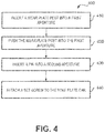
- Method 400 may include inserting a wear plate post into a first aperture in step 410.
- Method 400 may include pushing the wear plate post into the first aperture in step 420.
- Method 400 may include inserting a pin into a second aperture in step 430.
- Method 400 may include attaching a set-screw to the yoke plate ear in step 440.
- step 410 may include installing wear plate 142 onto yoke plate ear 310 by placing post 306 into first aperture 314.
- Step 420 may include pushing post 306 into first aperture 314 until contact surface 344 makes contact with yoke plate ear 310.
- Step 430 may include inserting or placing pin 302 into second aperture 316.
- pin 302 may also be inserted or placed into trench 308 or into retaining aperture 309.
- Step 440 may include attaching set-screw 304 to yoke plate ear 310 at second aperture 316 to retain pin 302 in second aperture 316.
- set-screw 304 may be threadingly attached to yoke plate ear 310.
Landscapes
- Engineering & Computer Science (AREA)
- Aviation & Aerospace Engineering (AREA)
- Mechanical Engineering (AREA)
- Chemical & Material Sciences (AREA)
- Combustion & Propulsion (AREA)
- Ocean & Marine Engineering (AREA)
- Supercharger (AREA)
Abstract
Description
- The present disclosure relates to propeller pitch change systems, and, more specifically, to a yoke plate arrangement for a propeller pitch change system.
- Propeller pitch change actuation systems for aircraft include propeller blades attached to trunnion bearings. The trunnion bearings are coupled between an aft yoke plate and a forward yoke plate. The yoke plates may be translated forward and aft to rotate the propeller blades and ultimately change their pitch angles. Due to blade loading, friction causing motion, vibrations, etc., the yoke plates may wear over time. A yoke plate having extensive wear may be replaced by removing the entire propeller pitch change actuation system from the aircraft to replace the yoke plate.
- Systems for propeller pitch change actuation are disclosed herein. A yoke plate arrangement may comprise a yoke plate, a wear plate comprising a wear surface and a contact surface, wherein a post extends from the contact surface, and a yoke plate ear extending from the yoke plate, wherein a first aperture is disposed in the yoke plate ear, the post located at least partially within the first aperture, the contact surface configured to be in contact with the yoke plate ear.
- In various embodiments, the first aperture may extend in a first direction and the yoke plate ear may comprise a second aperture extending in a second direction, the second direction being substantially perpendicular to the first direction, wherein the first aperture and the second aperture align. The yoke plate arrangement may further comprise a retaining feature, the retaining feature located at least partially within the second aperture and configured to retain the post inside of the first aperture. The post may include a trench extending in the second direction, the retaining feature located at least partially in the trench. The post may include a retaining aperture, the retaining feature located at least partially in the retaining aperture. The retaining feature may comprise a pin. The retaining feature may further comprise a set-screw, the set-screw threadingly attached to the second aperture. The first direction may comprise an axial direction and the second direction may comprise a circumferential direction. The wear surface may be configured to contact a trunnion. An anti-rotation surface may be disposed on the yoke plate ear. The anti-rotation surface may be configured to engage the wear plate to prevent the wear plate from rotating with respect to the yoke plate ear. The anti-rotation surface may be configured to engage a radially inward surface of the wear plate.
- A propeller pitch change actuation system may comprise a propeller coupled to a trunnion, a forward yoke plate coupled to a shaft, the forward yoke plate comprising a forward yoke plate ear extending from the forward yoke plate, an aft yoke plate coupled to the shaft, the aft yoke plate comprising an aft yoke plate ear extending from the aft yoke plate, wherein a first aft aperture is disposed in the aft yoke plate ear, the first aperture extending in a first direction, the trunnion located between the forward yoke plate ear and the aft yoke plate ear, and an aft wear plate coupled to the aft yoke plate ear comprising a wear surface and a contact surface, wherein a post extends from the contact surface, the post located at least partially inside of the first aperture.
- In various embodiments, the propeller pitch change actuation system may further comprise a forward wear plate coupled to the forward yoke plate ear. The wear surface may be in contact with the trunnion, the trunnion located between the aft wear plate and the forward wear plate. The contact surface may be in contact with the forward yoke plate ear. The propeller pitch change actuation system may further comprise a retaining feature configured to retain the post within the first aperture. A second aperture may be disposed in the aft yoke plate ear, the second aperture extending in a second direction, the retaining feature located at least partially within the second aperture.
- A method of installing a wear plate onto a yoke plate may comprise inserting a wear plate post into a first aperture disposed in the yoke plate, pushing the wear plate post into the first aperture until a contact surface of the wear plate makes contact with a yoke plate ear, inserting a pin into a second aperture disposed in the yoke plate, and attaching a set-screw to the yoke plate ear to retain the pin.
- In various embodiments, the pin may be inserted into a trench located in the wear plate post in response to the inserting the pin into the second aperture. The pin may be inserted into a retaining aperture located in the wear plate post in response to the inserting the pin into the second aperture.
- The foregoing features and elements may be combined in various combinations without exclusivity, unless expressly indicated otherwise. These features and elements as well as the operation thereof will become more apparent in light of the following description and the accompanying drawings. It should be understood, however, the following description and drawings are intended to be exemplary in nature and non-limiting.
- The subject matter of the present disclosure is particularly pointed out and distinctly claimed in the concluding portion of the specification. A more complete understanding of the present disclosure, however, may best be obtained by referring to the detailed description and claims when considered in connection with the figures, wherein like numerals denote like elements.
-
FIG. 1 illustrates a propeller pitch change actuation system, in accordance with various embodiments; -
FIG. 2A illustrates a radial view of a propeller in a feather blade angle position, in accordance with various embodiments; -
FIG. 2B illustrates a radial view of a propeller in a cruise blade angle position, in accordance with various embodiments; -
FIG. 2C illustrates a radial view of a propeller in a reverse blade angle position, in accordance with various embodiments; -
FIG. 3A illustrates a perspective view of yoke plate arrangement, in accordance with various embodiments; -
FIG. 3B illustrates an exploded view of a yoke plate arrangement, in accordance with various embodiments; -
FIG. 3C illustrates a wear plate for a yoke plate, in accordance with various embodiments; and -
FIG. 4 illustrates a method for installing a wear plate onto a yoke plate, in accordance with various embodiments. - The detailed description of exemplary embodiments herein makes reference to the accompanying drawings, which show exemplary embodiments by way of illustration. While these exemplary embodiments are described in sufficient detail to enable those skilled in the art to practice the exemplary embodiments of the disclosure, it should be understood that other embodiments may be realized and that logical changes and adaptations in design and construction may be made in accordance with this disclosure and the teachings herein. Thus, the detailed description herein is presented for purposes of illustration only and not limitation. The steps recited in any of the method or process descriptions may be executed in any order and are not necessarily limited to the order presented.
- Systems, methods and apparatus are provided herein. In the detailed description herein, references to "various embodiments", "one embodiment" "an embodiment", "an example embodiment", etc., indicate that the embodiment described may include a particular feature, structure, or characteristic, but every embodiment may not necessarily include the particular feature, structure, or characteristic. Moreover, such phrases are not necessarily referring to the same embodiment. Further, when a particular feature, structure, or characteristic is described in connection with an embodiment, it is submitted that it is within the knowledge of one skilled in the art to affect such feature, structure, or characteristic in connection with other embodiments whether or not explicitly described. After reading the description, it will be apparent to one skilled in the relevant art(s) how to implement the disclosure in alternative embodiments. Furthermore, any reference to singular includes plural embodiments, and any reference to more than one component or step may include a singular embodiment or step. Also, any reference to attached, fixed, connected or the like may include permanent, removable, temporary, partial, full and/or any other possible attachment option. Additionally, any reference to without contact (or similar phrases) may also include reduced contact or minimal contact. Surface shading lines may be used throughout the figures to denote different parts but not necessarily to denote the same or different materials.
- As used herein, "aft" refers to the direction associated with the tail (e.g., the back end) of an aircraft, or generally, to the direction of exhaust of the gas turbine. As used herein, "forward" refers to the direction associated with the nose (e.g., the front end) of an aircraft, or generally, to the direction of flight or motion.
- Typically, a propeller pitch change actuation systems for aircraft include a propeller blade comprising a trunnion bearing, wherein the trunnion bearing is disposed between an aft yoke plate and a forward yoke plate. The yoke plates may be translated forward and aft to rotate the propeller, in a manner similar to a bell crank. Due to blade loads, which may be extremely high (i.e., in the thousands of pounds of force range), the yoke plates may wear over time. Thus, at various maintenance intervals, the entire propeller pitch change actuation system may be removed from the aircraft to replace the yoke plates.
- A replaceable wear plate is provided herein. The wear plate is removably coupled to a yoke plate. The wear plate acts as a sacrificial part to extend the life of the yoke plate and to simplify maintenance due to worn parts, among other benefits.
- With reference to
FIG. 1 , a propeller pitchchange actuation system 100 is illustrated, in accordance with various embodiments. An xyz-axes is provided for ease of illustration. A propeller pitchchange actuation system 100 may include aforward yoke plate 134 and anaft yoke plate 132.Forward yoke plate 134 may be coupled toaft yoke plate 132.Forward yoke plate 134 may be coupled toshaft 130.Aft yoke plate 132 may be coupled toshaft 130.Forward yoke plate 134 andaft yoke plate 132 may be coupled topiston 128. Hydraulic pressure may be applied topiston 128 to move forwardyoke plate 134 andaft yoke plate 132 forward and aft (i.e., along the z-axis). Propeller pitchchange actuation system 100 may includepropeller blades 122.Propeller blades 122 may be coupled totrunnion 118. In various embodiments,trunnion 118 may comprise a trunnion bearing.Forward yoke plate 134 andaft yoke plate 132 may be coupled totrunnion 118. In various embodiments,trunnion 118 may be trapped betweenforward yoke plate 134 andaft yoke plate 132..Propeller blades 122 may rotate aboutrotation axis 120 in response toforward yoke plate 134 andaft yoke plate 132 moving forward and/or aft (i.e., along the z-axis). - With momentary reference to
FIG. 3A , a wear plate (also referred to herein as an aft wear plate) 142 may be coupled toaft yoke plate 132. A wear plate (also referred to herein as a forward wear plate) 144 may be coupled toforward yoke plate 134. - With reference to
FIG. 2A , a radial view ofpropeller blades 122 in a feather blade angle position is illustrated, in accordance with various embodiments. Aswear plate 142 and wearplate 144 travel from a forward position to an aft position (in the negative z-direction), as illustrated byFIGs. 2A-2C ,trunnion 118 may travel in an arc-like motion aboutrotation axis 120. More particularly,trunnion 118 may travel in an arc aboutrotation axis 120 having a radius 204. - With reference to
FIG. 2B , a radial view ofpropeller blades 122 in a cruise blade angle position is illustrated, in accordance with various embodiments.Propeller blades 122 may rotate in arotational direction 202, (a first rotational direction, or the clockwise direction as illustrated inFIG. 2B ) in response to wearplate 142 and wearplate 144 moving aft in the negative z-direction.Trunnion 118 may move relative to wearplate 142 and wearplate 144 in response to this motion. For example,trunnion 118 is illustrated as having moved outboard (in the x-direction) inFIG. 2B with respect to wearplate 142 and wearplate 144. Such relative motion may cause at least a portion ofwear plate 142 and wearplate 144 to wear away or grind down over time. - With reference to
FIG. 2C , a radial view ofpropeller blades 122 in a reverse blade angle position is illustrated, in accordance with various embodiments. The position oftrunnion 118 relative topropeller 122 may be fixed. Thus,trunnion 118 may move in the arc-like motion defined by radius 204 (seeFIG. 2A ) aboutrotation axis 120, in response to wearplate 142 and wearplate 144 moving linearly motion (i.e., along the z-axis). - With reference to
FIG. 3A , a perspective view ofyoke plate arrangement 300 is illustrated, in accordance with various embodiments.Yoke plate arrangement 300 may includeaft yoke plate 132 and wearplate 142.Aft yoke plate 132 may comprise a yoke plate ear (also referred to herein as an aft yoke plate ear) 310.Yoke plate ear 310 may extend fromaft yoke plate 132.Yoke plate ear 310 may extend fromaft yoke plate 132 in a radial direction or an outboard direction (i.e., in the positive y-direction).Wear plate 142 may comprise awear surface 343.Wear surface 343 may be configured to contact trunnion 118 (seeFIG. 1 ).Wear plate 142 is illustrated in an installed position. In various embodiments, wearplate 142 may comprise various surface coatings to prevent corrosion and/or increase hardness. - In various embodiments, wear
plate 142 and/oraft yoke plate 132 may comprise steel. In various embodiments, wearplate 142 and/oraft yoke plate 132 may be hardened during a carburizing process to provide enhanced wear resistance. In various embodiments,yoke plate arrangement 300 may includeforward yoke plate 134. Similar toaft yoke plate 132,forward yoke plate 134 may comprise a yoke plate ear (also referred to herein as a forward yoke plate ear) 311. Thus, wearplate 144 may be coupled toyoke plate ear 311.Wear plate 144 may be coupled toyoke plate ear 311 in a similar manner aswear plate 142 is coupled toyoke plate ear 310. - With reference to
FIG. 3B , an exploded-view ofyoke plate arrangement 300 is illustrated, in accordance with various embodiments.Wear plate 142 may comprise a post (also referred to herein as a wear plate post) 306. With momentary reference toFIG. 3B and FIG. 3C , post 306 may extend fromcontact surface 344.Contact surface 344 may make contact withyoke plate ear 310 when in an installed position. -
Yoke plate ear 310 may include afirst aperture 314.First aperture 314 may extend in the axial direction (z-direction or first direction).Yoke plate ear 310 may include asecond aperture 316.Second aperture 316 may extend in the circumferential direction (x-direction or second direction). In various embodiments,first aperture 314 may be substantially perpendicular tosecond aperture 316. In various embodiments,first aperture 314 andsecond aperture 316 may intersect or align. -
Yoke plate arrangement 300 may include a retaining feature 303. In various embodiments, retaining feature 303 may comprise a pin 302. In various embodiments, retaining feature 303 may comprise a set-screw 304. In various embodiments, retaining feature 303 may be configured to preventpost 306 from moving out offirst aperture 314. -
Post 306 may comprise a cylindrical geometry as illustrated inFIG. 3B . However, post 306 may comprise any suitable geometry, such as triangular, square, elliptical, or trapezoidal, for example. Atrench 308 may be disposed inpost 306. In various embodiments,trench 308 may comprise a cut-out 320. Although illustrated inFIG. 3B as comprising a trench, in various embodiments and with momentary additional reference toFIG. 3C , post 306 may comprise a retainingaperture 309. In various embodiments, retainingaperture 309 may be drilled intopost 306. In various embodiments, retainingaperture 309 may be cast intopost 306. In various embodiments, retainingaperture 309 may comprise a bore. In various embodiments, retaining feature 303 may extend throughsecond aperture 316 and be located at least partially withintrench 308. In various embodiments, retaining feature 303 may extend throughsecond aperture 316 and be located at least partially within retainingaperture 309. In this manner, retaining feature 303 may be configured to retainpost 306 inside offirst aperture 314. In various embodiments,trench 308 may extend in the circumferential direction (x-direction, also referred to as asecond direction). In various embodiments, retainingaperture 309 may extend in the circumferential direction (x-direction or second direction). - With reference now to
FIG. 3B , set-screw 304 may threadingly attach tosecond aperture 316. In various embodiments, set-screw 304 may retain pin 302 withinsecond aperture 316. Although illustrated inFIG. 3B as two separate parts, pin 302 and set-screw 304 may comprise a single unitary part, in accordance with various embodiments. - With reference to
FIG. 3A , ananti-rotation surface 312 may be disposed onyoke plate ear 310, in accordance with various embodiments.Anti-rotation surface 312 may be configured to engagewear plate 142.Anti-rotation surface 312 may prevent thewear plate 142 from rotating with respect toyoke plate ear 310.Anti-rotation surface 312 may engage a radiallyinward surface 346 ofwear plate 142. - With reference to
FIG. 4 , amethod 400 for installing a wear plate onto a yoke plate is provided, in accordance with various embodiments.Method 400 may include inserting a wear plate post into a first aperture instep 410.Method 400 may include pushing the wear plate post into the first aperture instep 420.Method 400 may include inserting a pin into a second aperture instep 430.Method 400 may include attaching a set-screw to the yoke plate ear instep 440. - With further reference to
FIG. 3B and FIG. 3C ,step 410 may include installingwear plate 142 ontoyoke plate ear 310 by placingpost 306 intofirst aperture 314. Step 420 may include pushingpost 306 intofirst aperture 314 untilcontact surface 344 makes contact withyoke plate ear 310. Step 430 may include inserting or placing pin 302 intosecond aperture 316. In response, pin 302 may also be inserted or placed intotrench 308 or into retainingaperture 309. Step 440 may include attaching set-screw 304 toyoke plate ear 310 atsecond aperture 316 to retain pin 302 insecond aperture 316. In various embodiments, set-screw 304 may be threadingly attached toyoke plate ear 310. - Benefits and other advantages have been described herein with regard to specific embodiments. Furthermore, the connecting lines shown in the various figures contained herein are intended to represent exemplary functional relationships and/or physical couplings between the various elements. It should be noted that many alternative or additional functional relationships or physical connections may be present in a practical system. However, the benefits, advantages, and any elements that may cause any benefit or advantage to occur or become more pronounced are not to be construed as critical, required, or essential features or elements of the disclosure. The scope of the disclosure is accordingly to be limited by nothing other than the appended claims, in which reference to an element in the singular is not intended to mean "one and only one" unless explicitly so stated, but rather "one or more." Moreover, where a phrase similar to "at least one of A, B, or C" is used in the claims, it is intended that the phrase be interpreted to mean that A alone may be present in an embodiment, B alone may be present in an embodiment, C alone may be present in an embodiment, or that any combination of the elements A, B and C may be present in a single embodiment; for example, A and B, A and C, B and C, or A and B and C.
- Furthermore, no element, component, or method step in the present disclosure is intended to be dedicated to the public regardless of whether the element, component, or method step is explicitly recited in the claims. No claim element herein is to be construed under the provisions of 35 U.S.C. 112(f), unless the element is expressly recited using the phrase "means for." As used herein, the terms "comprises", "comprising", or any other variation thereof, are intended to cover a non-exclusive inclusion, such that a process, method, article, or apparatus that comprises a list of elements does not include only those elements but may include other elements not expressly listed or inherent to such process, method, article, or apparatus.
Claims (15)
- A yoke plate arrangement comprising:a yoke plate;a wear plate comprising a wear surface and a contact surface, wherein a post extends from the contact surface; anda yoke plate ear extending from the yoke plate, wherein a first aperture is disposed in the yoke plate ear, the post located at least partially within the first aperture, the contact surface configured to be in contact with the yoke plate ear.
- The yoke plate arrangement of claim 1, wherein the first aperture extends in a first direction and the yoke plate ear comprises a second aperture extending in a second direction, the second direction being substantially perpendicular to the first direction, wherein the first aperture and the second aperture align.
- The yoke plate arrangement of claim 2, further comprising a retaining feature, the retaining feature located at least partially within the second aperture and configured to retain the post inside of the first aperture.
- The yoke plate arrangement of claim 3, wherein the post includes a trench extending in the second direction, the retaining feature located at least partially in the trench, or
wherein the post includes a retaining aperture, the retaining feature located at least partially in the retaining aperture. - The yoke plate arrangement of claim 3, wherein the retaining feature comprises a pin, and optionally
wherein the retaining feature further comprises a set-screw, the set-screw threadingly attached to the second aperture. - The yoke plate arrangement of claim 2, wherein the first direction comprises an axial direction and the second direction comprises a circumferential direction.
- The yoke plate arrangement of claim 2, wherein the wear surface is configured to contact a trunnion.
- The yoke plate arrangement of any preceding claim, wherein an anti-rotation surface disposed on the yoke plate ear, the anti-rotation surface configured to engage the wear plate to prevent the wear plate from rotating with respect to the yoke plate ear, and optionally
wherein the anti-rotation surface is configured to engage a radially inward surface of the wear plate. - A propeller pitch change actuation system, comprising:a propeller coupled to a trunnion;a forward yoke plate coupled to a shaft, the forward yoke plate comprising a forward yoke plate ear extending from the forward yoke plate;an aft yoke plate coupled to the shaft, the aft yoke plate comprising an aft yoke plate ear extending from the aft yoke plate, wherein a first aperture is disposed in the aft yoke plate ear, the first aperture extending in a first direction, the trunnion located between the forward yoke plate ear and the aft yoke plate ear; andan aft wear plate coupled to the aft yoke plate ear comprising a wear surface and a contact surface, wherein a post extends from the contact surface, the post located at least partially inside of the first aperture.
- The propeller pitch change actuation system of claim 9, wherein the propeller pitch change actuation system further comprises a forward wear plate coupled to the forward yoke plate ear.
- The propeller pitch change actuation system of claim 10, wherein the wear surface is in contact with the trunnion, the trunnion located between the aft wear plate and the forward wear plate.
- The propeller pitch change actuation system of claim 11, wherein the contact surface is in contact with the forward yoke plate ear.
- The propeller pitch change actuation system of claim 12, further comprising a retaining feature configured to retain the post within the first aperture, and optionally
wherein a second aperture is disposed in the aft yoke plate ear, the second aperture extending in a second direction, the retaining feature located at least partially within the second aperture. - A method for installing a wear plate onto a yoke plate comprising:inserting a wear plate post into a first aperture disposed in the yoke plate;pushing the wear plate post into the first aperture until a contact surface of the wear plate makes contact with a yoke plate ear;inserting a pin into a second aperture disposed in the yoke plate; andattaching a set-screw to the yoke plate ear to retain the pin.
- The method of claim 14, wherein the pin is inserted into a trench located in the wear plate post in response to the inserting the pin into the second aperture, or
wherein the pin is inserted into a retaining aperture located in the wear plate post in response to the inserting the pin into the second aperture.
Applications Claiming Priority (1)
| Application Number | Priority Date | Filing Date | Title |
|---|---|---|---|
| US15/074,632 US10077103B2 (en) | 2016-03-18 | 2016-03-18 | Propeller pitch change actuation system |
Publications (2)
| Publication Number | Publication Date |
|---|---|
| EP3219609A1 true EP3219609A1 (en) | 2017-09-20 |
| EP3219609B1 EP3219609B1 (en) | 2019-10-23 |
Family
ID=58265838
Family Applications (1)
| Application Number | Title | Priority Date | Filing Date |
|---|---|---|---|
| EP17159888.1A Active EP3219609B1 (en) | 2016-03-18 | 2017-03-08 | Propeller pitch change actuation system |
Country Status (2)
| Country | Link |
|---|---|
| US (1) | US10077103B2 (en) |
| EP (1) | EP3219609B1 (en) |
Families Citing this family (1)
| Publication number | Priority date | Publication date | Assignee | Title |
|---|---|---|---|---|
| FR3072714B1 (en) * | 2017-10-24 | 2019-09-27 | Safran Transmission Systems | OIL TRANSFER TUBE FOR A STEER CONTROL SYSTEM OF A TURBOMACHINE PROPELLER |
Citations (5)
| Publication number | Priority date | Publication date | Assignee | Title |
|---|---|---|---|---|
| US414746A (en) * | 1889-11-12 | John jay anderson | ||
| US5174718A (en) * | 1991-08-12 | 1992-12-29 | United Technologies Corporation | Blade pitch change control system |
| EP2003055A2 (en) * | 2007-06-11 | 2008-12-17 | Hamilton Sundstrand Corporation | Blade pitch actuation mechanism |
| US20100008779A1 (en) * | 2008-07-14 | 2010-01-14 | Carvalho Paul A | Integrated actuator for a propeller system |
| US20140169961A1 (en) * | 2012-12-13 | 2014-06-19 | Hamilton Sundstrand Corporation | Propeller rotor balancing system |
Family Cites Families (11)
| Publication number | Priority date | Publication date | Assignee | Title |
|---|---|---|---|---|
| US3300258A (en) * | 1964-03-05 | 1967-01-24 | Teleflex Inc | Bearing and method for making same |
| US6514044B2 (en) * | 2000-12-21 | 2003-02-04 | Hamilton Sundstrand Corporation | Offset crowned roller assembly for variable pitch propellers |
| US6511292B2 (en) * | 2001-06-27 | 2003-01-28 | Hamilton Sundstrand Corporation | Backup governing system for a variable pitch propeller |
| US7296969B2 (en) * | 2005-10-12 | 2007-11-20 | Hamilton Sundstrand Corporation | Propeller pitch change system |
| US7930827B2 (en) * | 2006-05-22 | 2011-04-26 | Moxee Innovations Corporation | Split bearing and method of making the same |
| US7901137B1 (en) * | 2008-01-11 | 2011-03-08 | Us Synthetic Corporation | Bearing assembly, and bearing apparatus and motor assembly using same |
| US8439640B2 (en) * | 2008-07-15 | 2013-05-14 | Hamilton Sundstrand Corporation | Propeller blade pitch control system |
| US7857517B1 (en) * | 2009-06-12 | 2010-12-28 | Vicars Berton L | Connecting rod bearing housing |
| US8529205B2 (en) * | 2009-12-10 | 2013-09-10 | Hamilton Sundstrand Corporation | Passive cyclic pitch control |
| JP5546638B2 (en) * | 2010-08-31 | 2014-07-09 | 三菱重工業株式会社 | Planetary gear mechanism and wind power generator |
| DE102010041160A1 (en) * | 2010-09-21 | 2012-03-22 | Gebr. Bode Gmbh & Co. Kg | sliding door drive |
-
2016
- 2016-03-18 US US15/074,632 patent/US10077103B2/en active Active
-
2017
- 2017-03-08 EP EP17159888.1A patent/EP3219609B1/en active Active
Patent Citations (5)
| Publication number | Priority date | Publication date | Assignee | Title |
|---|---|---|---|---|
| US414746A (en) * | 1889-11-12 | John jay anderson | ||
| US5174718A (en) * | 1991-08-12 | 1992-12-29 | United Technologies Corporation | Blade pitch change control system |
| EP2003055A2 (en) * | 2007-06-11 | 2008-12-17 | Hamilton Sundstrand Corporation | Blade pitch actuation mechanism |
| US20100008779A1 (en) * | 2008-07-14 | 2010-01-14 | Carvalho Paul A | Integrated actuator for a propeller system |
| US20140169961A1 (en) * | 2012-12-13 | 2014-06-19 | Hamilton Sundstrand Corporation | Propeller rotor balancing system |
Also Published As
| Publication number | Publication date |
|---|---|
| US20170267328A1 (en) | 2017-09-21 |
| US10077103B2 (en) | 2018-09-18 |
| EP3219609B1 (en) | 2019-10-23 |
Similar Documents
| Publication | Publication Date | Title |
|---|---|---|
| EP3168491B1 (en) | Single fastener brake disk insert retainer | |
| EP2060809B1 (en) | Fan shaft retention | |
| CN113474252B (en) | Orientation-adjustable and reduced-volume blade pivots for turbine engine fan hubs | |
| JP2008232147A (en) | Turbomachine fan | |
| CN115968428B (en) | A system for controlling the pitch of propeller blades in an aircraft turbine engine. | |
| EP3168492B1 (en) | Low radial profile brake disk insert retainer | |
| CN108798796B (en) | Variable Stator Vane Actuator Overload Indicator Sleeve | |
| CA2863340C (en) | Propeller assembly and propeller blade retention assembly | |
| JP6302511B2 (en) | Hub assembly and propeller assembly | |
| EP3219609B1 (en) | Propeller pitch change actuation system | |
| US10633067B2 (en) | Method and system for improving flow characteristics in marine propellers | |
| EP3051061B1 (en) | Gas turbine engine disk balancing system | |
| CN119317780A (en) | Aircraft turbine with variable pitch propeller blades | |
| CN115989178A (en) | System for controlling the pitch setting of propeller blades of an aircraft turbine engine | |
| EP2865878B1 (en) | Gimbal pin for jet propulsion system | |
| CN114787033A (en) | Improvements in Radial Locking of Orientation Adjustable Blade Pivots for Turbine Fan Hubs | |
| EP4223635A1 (en) | Compact propeller blade retention assembly | |
| US20190017638A1 (en) | Balking tab to control duct coupling clocking | |
| EP3081758B1 (en) | Aircraft engine fan assembly with a blade lock retainer | |
| US9828945B2 (en) | Ram air turbine driveshaft gear and bearing arrangement | |
| EP3053701A1 (en) | Flangeless conical sleeve and method of repair |
Legal Events
| Date | Code | Title | Description |
|---|---|---|---|
| PUAI | Public reference made under article 153(3) epc to a published international application that has entered the european phase |
Free format text: ORIGINAL CODE: 0009012 |
|
| STAA | Information on the status of an ep patent application or granted ep patent |
Free format text: STATUS: THE APPLICATION HAS BEEN PUBLISHED |
|
| AK | Designated contracting states |
Kind code of ref document: A1 Designated state(s): AL AT BE BG CH CY CZ DE DK EE ES FI FR GB GR HR HU IE IS IT LI LT LU LV MC MK MT NL NO PL PT RO RS SE SI SK SM TR |
|
| AX | Request for extension of the european patent |
Extension state: BA ME |
|
| STAA | Information on the status of an ep patent application or granted ep patent |
Free format text: STATUS: REQUEST FOR EXAMINATION WAS MADE |
|
| 17P | Request for examination filed |
Effective date: 20180320 |
|
| RBV | Designated contracting states (corrected) |
Designated state(s): AL AT BE BG CH CY CZ DE DK EE ES FI FR GB GR HR HU IE IS IT LI LT LU LV MC MK MT NL NO PL PT RO RS SE SI SK SM TR |
|
| GRAP | Despatch of communication of intention to grant a patent |
Free format text: ORIGINAL CODE: EPIDOSNIGR1 |
|
| STAA | Information on the status of an ep patent application or granted ep patent |
Free format text: STATUS: GRANT OF PATENT IS INTENDED |
|
| INTG | Intention to grant announced |
Effective date: 20181221 |
|
| GRAJ | Information related to disapproval of communication of intention to grant by the applicant or resumption of examination proceedings by the epo deleted |
Free format text: ORIGINAL CODE: EPIDOSDIGR1 |
|
| STAA | Information on the status of an ep patent application or granted ep patent |
Free format text: STATUS: REQUEST FOR EXAMINATION WAS MADE |
|
| GRAP | Despatch of communication of intention to grant a patent |
Free format text: ORIGINAL CODE: EPIDOSNIGR1 |
|
| STAA | Information on the status of an ep patent application or granted ep patent |
Free format text: STATUS: GRANT OF PATENT IS INTENDED |
|
| INTC | Intention to grant announced (deleted) | ||
| INTG | Intention to grant announced |
Effective date: 20190516 |
|
| RIN1 | Information on inventor provided before grant (corrected) |
Inventor name: PLICKYS, MARK R. |
|
| GRAS | Grant fee paid |
Free format text: ORIGINAL CODE: EPIDOSNIGR3 |
|
| GRAA | (expected) grant |
Free format text: ORIGINAL CODE: 0009210 |
|
| STAA | Information on the status of an ep patent application or granted ep patent |
Free format text: STATUS: THE PATENT HAS BEEN GRANTED |
|
| AK | Designated contracting states |
Kind code of ref document: B1 Designated state(s): AL AT BE BG CH CY CZ DE DK EE ES FI FR GB GR HR HU IE IS IT LI LT LU LV MC MK MT NL NO PL PT RO RS SE SI SK SM TR |
|
| REG | Reference to a national code |
Ref country code: GB Ref legal event code: FG4D |
|
| REG | Reference to a national code |
Ref country code: CH Ref legal event code: EP |
|
| REG | Reference to a national code |
Ref country code: IE Ref legal event code: FG4D |
|
| REG | Reference to a national code |
Ref country code: DE Ref legal event code: R096 Ref document number: 602017007948 Country of ref document: DE |
|
| REG | Reference to a national code |
Ref country code: AT Ref legal event code: REF Ref document number: 1193359 Country of ref document: AT Kind code of ref document: T Effective date: 20191115 |
|
| REG | Reference to a national code |
Ref country code: NL Ref legal event code: MP Effective date: 20191023 |
|
| REG | Reference to a national code |
Ref country code: LT Ref legal event code: MG4D |
|
| PG25 | Lapsed in a contracting state [announced via postgrant information from national office to epo] |
Ref country code: BG Free format text: LAPSE BECAUSE OF FAILURE TO SUBMIT A TRANSLATION OF THE DESCRIPTION OR TO PAY THE FEE WITHIN THE PRESCRIBED TIME-LIMIT Effective date: 20200123 Ref country code: GR Free format text: LAPSE BECAUSE OF FAILURE TO SUBMIT A TRANSLATION OF THE DESCRIPTION OR TO PAY THE FEE WITHIN THE PRESCRIBED TIME-LIMIT Effective date: 20200124 Ref country code: PT Free format text: LAPSE BECAUSE OF FAILURE TO SUBMIT A TRANSLATION OF THE DESCRIPTION OR TO PAY THE FEE WITHIN THE PRESCRIBED TIME-LIMIT Effective date: 20200224 Ref country code: LT Free format text: LAPSE BECAUSE OF FAILURE TO SUBMIT A TRANSLATION OF THE DESCRIPTION OR TO PAY THE FEE WITHIN THE PRESCRIBED TIME-LIMIT Effective date: 20191023 Ref country code: FI Free format text: LAPSE BECAUSE OF FAILURE TO SUBMIT A TRANSLATION OF THE DESCRIPTION OR TO PAY THE FEE WITHIN THE PRESCRIBED TIME-LIMIT Effective date: 20191023 Ref country code: LV Free format text: LAPSE BECAUSE OF FAILURE TO SUBMIT A TRANSLATION OF THE DESCRIPTION OR TO PAY THE FEE WITHIN THE PRESCRIBED TIME-LIMIT Effective date: 20191023 Ref country code: SE Free format text: LAPSE BECAUSE OF FAILURE TO SUBMIT A TRANSLATION OF THE DESCRIPTION OR TO PAY THE FEE WITHIN THE PRESCRIBED TIME-LIMIT Effective date: 20191023 Ref country code: PL Free format text: LAPSE BECAUSE OF FAILURE TO SUBMIT A TRANSLATION OF THE DESCRIPTION OR TO PAY THE FEE WITHIN THE PRESCRIBED TIME-LIMIT Effective date: 20191023 Ref country code: NO Free format text: LAPSE BECAUSE OF FAILURE TO SUBMIT A TRANSLATION OF THE DESCRIPTION OR TO PAY THE FEE WITHIN THE PRESCRIBED TIME-LIMIT Effective date: 20200123 Ref country code: NL Free format text: LAPSE BECAUSE OF FAILURE TO SUBMIT A TRANSLATION OF THE DESCRIPTION OR TO PAY THE FEE WITHIN THE PRESCRIBED TIME-LIMIT Effective date: 20191023 |
|
| PG25 | Lapsed in a contracting state [announced via postgrant information from national office to epo] |
Ref country code: IS Free format text: LAPSE BECAUSE OF FAILURE TO SUBMIT A TRANSLATION OF THE DESCRIPTION OR TO PAY THE FEE WITHIN THE PRESCRIBED TIME-LIMIT Effective date: 20200224 Ref country code: RS Free format text: LAPSE BECAUSE OF FAILURE TO SUBMIT A TRANSLATION OF THE DESCRIPTION OR TO PAY THE FEE WITHIN THE PRESCRIBED TIME-LIMIT Effective date: 20191023 Ref country code: HR Free format text: LAPSE BECAUSE OF FAILURE TO SUBMIT A TRANSLATION OF THE DESCRIPTION OR TO PAY THE FEE WITHIN THE PRESCRIBED TIME-LIMIT Effective date: 20191023 |
|
| PG25 | Lapsed in a contracting state [announced via postgrant information from national office to epo] |
Ref country code: AL Free format text: LAPSE BECAUSE OF FAILURE TO SUBMIT A TRANSLATION OF THE DESCRIPTION OR TO PAY THE FEE WITHIN THE PRESCRIBED TIME-LIMIT Effective date: 20191023 |
|
| REG | Reference to a national code |
Ref country code: DE Ref legal event code: R097 Ref document number: 602017007948 Country of ref document: DE |
|
| PG2D | Information on lapse in contracting state deleted |
Ref country code: IS |
|
| PG25 | Lapsed in a contracting state [announced via postgrant information from national office to epo] |
Ref country code: ES Free format text: LAPSE BECAUSE OF FAILURE TO SUBMIT A TRANSLATION OF THE DESCRIPTION OR TO PAY THE FEE WITHIN THE PRESCRIBED TIME-LIMIT Effective date: 20191023 Ref country code: EE Free format text: LAPSE BECAUSE OF FAILURE TO SUBMIT A TRANSLATION OF THE DESCRIPTION OR TO PAY THE FEE WITHIN THE PRESCRIBED TIME-LIMIT Effective date: 20191023 Ref country code: DK Free format text: LAPSE BECAUSE OF FAILURE TO SUBMIT A TRANSLATION OF THE DESCRIPTION OR TO PAY THE FEE WITHIN THE PRESCRIBED TIME-LIMIT Effective date: 20191023 Ref country code: RO Free format text: LAPSE BECAUSE OF FAILURE TO SUBMIT A TRANSLATION OF THE DESCRIPTION OR TO PAY THE FEE WITHIN THE PRESCRIBED TIME-LIMIT Effective date: 20191023 Ref country code: CZ Free format text: LAPSE BECAUSE OF FAILURE TO SUBMIT A TRANSLATION OF THE DESCRIPTION OR TO PAY THE FEE WITHIN THE PRESCRIBED TIME-LIMIT Effective date: 20191023 Ref country code: IS Free format text: LAPSE BECAUSE OF FAILURE TO SUBMIT A TRANSLATION OF THE DESCRIPTION OR TO PAY THE FEE WITHIN THE PRESCRIBED TIME-LIMIT Effective date: 20200223 |
|
| REG | Reference to a national code |
Ref country code: AT Ref legal event code: MK05 Ref document number: 1193359 Country of ref document: AT Kind code of ref document: T Effective date: 20191023 |
|
| PLBE | No opposition filed within time limit |
Free format text: ORIGINAL CODE: 0009261 |
|
| STAA | Information on the status of an ep patent application or granted ep patent |
Free format text: STATUS: NO OPPOSITION FILED WITHIN TIME LIMIT |
|
| PG25 | Lapsed in a contracting state [announced via postgrant information from national office to epo] |
Ref country code: IT Free format text: LAPSE BECAUSE OF FAILURE TO SUBMIT A TRANSLATION OF THE DESCRIPTION OR TO PAY THE FEE WITHIN THE PRESCRIBED TIME-LIMIT Effective date: 20191023 Ref country code: SM Free format text: LAPSE BECAUSE OF FAILURE TO SUBMIT A TRANSLATION OF THE DESCRIPTION OR TO PAY THE FEE WITHIN THE PRESCRIBED TIME-LIMIT Effective date: 20191023 Ref country code: SK Free format text: LAPSE BECAUSE OF FAILURE TO SUBMIT A TRANSLATION OF THE DESCRIPTION OR TO PAY THE FEE WITHIN THE PRESCRIBED TIME-LIMIT Effective date: 20191023 |
|
| 26N | No opposition filed |
Effective date: 20200724 |
|
| REG | Reference to a national code |
Ref country code: DE Ref legal event code: R119 Ref document number: 602017007948 Country of ref document: DE |
|
| PG25 | Lapsed in a contracting state [announced via postgrant information from national office to epo] |
Ref country code: MC Free format text: LAPSE BECAUSE OF FAILURE TO SUBMIT A TRANSLATION OF THE DESCRIPTION OR TO PAY THE FEE WITHIN THE PRESCRIBED TIME-LIMIT Effective date: 20191023 |
|
| REG | Reference to a national code |
Ref country code: CH Ref legal event code: PL |
|
| PG25 | Lapsed in a contracting state [announced via postgrant information from national office to epo] |
Ref country code: AT Free format text: LAPSE BECAUSE OF FAILURE TO SUBMIT A TRANSLATION OF THE DESCRIPTION OR TO PAY THE FEE WITHIN THE PRESCRIBED TIME-LIMIT Effective date: 20191023 Ref country code: SI Free format text: LAPSE BECAUSE OF FAILURE TO SUBMIT A TRANSLATION OF THE DESCRIPTION OR TO PAY THE FEE WITHIN THE PRESCRIBED TIME-LIMIT Effective date: 20191023 |
|
| REG | Reference to a national code |
Ref country code: BE Ref legal event code: MM Effective date: 20200331 |
|
| PG25 | Lapsed in a contracting state [announced via postgrant information from national office to epo] |
Ref country code: LU Free format text: LAPSE BECAUSE OF NON-PAYMENT OF DUE FEES Effective date: 20200308 |
|
| PG25 | Lapsed in a contracting state [announced via postgrant information from national office to epo] |
Ref country code: LI Free format text: LAPSE BECAUSE OF NON-PAYMENT OF DUE FEES Effective date: 20200331 Ref country code: IE Free format text: LAPSE BECAUSE OF NON-PAYMENT OF DUE FEES Effective date: 20200308 Ref country code: DE Free format text: LAPSE BECAUSE OF NON-PAYMENT OF DUE FEES Effective date: 20201001 Ref country code: CH Free format text: LAPSE BECAUSE OF NON-PAYMENT OF DUE FEES Effective date: 20200331 |
|
| PG25 | Lapsed in a contracting state [announced via postgrant information from national office to epo] |
Ref country code: BE Free format text: LAPSE BECAUSE OF NON-PAYMENT OF DUE FEES Effective date: 20200331 |
|
| PG25 | Lapsed in a contracting state [announced via postgrant information from national office to epo] |
Ref country code: TR Free format text: LAPSE BECAUSE OF FAILURE TO SUBMIT A TRANSLATION OF THE DESCRIPTION OR TO PAY THE FEE WITHIN THE PRESCRIBED TIME-LIMIT Effective date: 20191023 Ref country code: MT Free format text: LAPSE BECAUSE OF FAILURE TO SUBMIT A TRANSLATION OF THE DESCRIPTION OR TO PAY THE FEE WITHIN THE PRESCRIBED TIME-LIMIT Effective date: 20191023 Ref country code: CY Free format text: LAPSE BECAUSE OF FAILURE TO SUBMIT A TRANSLATION OF THE DESCRIPTION OR TO PAY THE FEE WITHIN THE PRESCRIBED TIME-LIMIT Effective date: 20191023 |
|
| PG25 | Lapsed in a contracting state [announced via postgrant information from national office to epo] |
Ref country code: MK Free format text: LAPSE BECAUSE OF FAILURE TO SUBMIT A TRANSLATION OF THE DESCRIPTION OR TO PAY THE FEE WITHIN THE PRESCRIBED TIME-LIMIT Effective date: 20191023 |
|
| P01 | Opt-out of the competence of the unified patent court (upc) registered |
Effective date: 20230522 |
|
| PGFP | Annual fee paid to national office [announced via postgrant information from national office to epo] |
Ref country code: GB Payment date: 20260219 Year of fee payment: 10 |
|
| PGFP | Annual fee paid to national office [announced via postgrant information from national office to epo] |
Ref country code: FR Payment date: 20260219 Year of fee payment: 10 |