EP3219597A1 - Caliper group of a disc brake for a bicycle and method for mounting a caliper group on a load-bearing element of a bicycle - Google Patents
Caliper group of a disc brake for a bicycle and method for mounting a caliper group on a load-bearing element of a bicycle Download PDFInfo
- Publication number
- EP3219597A1 EP3219597A1 EP17160130.5A EP17160130A EP3219597A1 EP 3219597 A1 EP3219597 A1 EP 3219597A1 EP 17160130 A EP17160130 A EP 17160130A EP 3219597 A1 EP3219597 A1 EP 3219597A1
- Authority
- EP
- European Patent Office
- Prior art keywords
- load
- bearing element
- caliper
- tube
- group
- Prior art date
- Legal status (The legal status is an assumption and is not a legal conclusion. Google has not performed a legal analysis and makes no representation as to the accuracy of the status listed.)
- Withdrawn
Links
Images




Classifications
-
- B—PERFORMING OPERATIONS; TRANSPORTING
- B62—LAND VEHICLES FOR TRAVELLING OTHERWISE THAN ON RAILS
- B62L—BRAKES SPECIALLY ADAPTED FOR CYCLES
- B62L1/00—Brakes; Arrangements thereof
- B62L1/02—Brakes; Arrangements thereof in which cycle wheels are engaged by brake elements
-
- B—PERFORMING OPERATIONS; TRANSPORTING
- B60—VEHICLES IN GENERAL
- B60T—VEHICLE BRAKE CONTROL SYSTEMS OR PARTS THEREOF; BRAKE CONTROL SYSTEMS OR PARTS THEREOF, IN GENERAL; ARRANGEMENT OF BRAKING ELEMENTS ON VEHICLES IN GENERAL; PORTABLE DEVICES FOR PREVENTING UNWANTED MOVEMENT OF VEHICLES; VEHICLE MODIFICATIONS TO FACILITATE COOLING OF BRAKES
- B60T17/00—Component parts, details, or accessories of power brake systems not covered by groups B60T8/00, B60T13/00 or B60T15/00, or presenting other characteristic features
- B60T17/04—Arrangements of piping, valves in the piping, e.g. cut-off valves, couplings or air hoses
- B60T17/046—Devices for pipe guiding and fixing
-
- B—PERFORMING OPERATIONS; TRANSPORTING
- B62—LAND VEHICLES FOR TRAVELLING OTHERWISE THAN ON RAILS
- B62K—CYCLES; CYCLE FRAMES; CYCLE STEERING DEVICES; RIDER-OPERATED TERMINAL CONTROLS SPECIALLY ADAPTED FOR CYCLES; CYCLE AXLE SUSPENSIONS; CYCLE SIDECARS, FORECARS, OR THE LIKE
- B62K19/00—Cycle frames
- B62K19/30—Frame parts shaped to receive other cycle parts or accessories
- B62K19/38—Frame parts shaped to receive other cycle parts or accessories for attaching brake members
-
- B—PERFORMING OPERATIONS; TRANSPORTING
- B62—LAND VEHICLES FOR TRAVELLING OTHERWISE THAN ON RAILS
- B62L—BRAKES SPECIALLY ADAPTED FOR CYCLES
- B62L1/00—Brakes; Arrangements thereof
- B62L1/005—Brakes; Arrangements thereof constructional features of brake elements, e.g. fastening of brake blocks in their holders
-
- F—MECHANICAL ENGINEERING; LIGHTING; HEATING; WEAPONS; BLASTING
- F16—ENGINEERING ELEMENTS AND UNITS; GENERAL MEASURES FOR PRODUCING AND MAINTAINING EFFECTIVE FUNCTIONING OF MACHINES OR INSTALLATIONS; THERMAL INSULATION IN GENERAL
- F16D—COUPLINGS FOR TRANSMITTING ROTATION; CLUTCHES; BRAKES
- F16D55/00—Brakes with substantially-radial braking surfaces pressed together in axial direction, e.g. disc brakes
- F16D55/02—Brakes with substantially-radial braking surfaces pressed together in axial direction, e.g. disc brakes with axially-movable discs or pads pressed against axially-located rotating members
- F16D55/22—Brakes with substantially-radial braking surfaces pressed together in axial direction, e.g. disc brakes with axially-movable discs or pads pressed against axially-located rotating members by clamping an axially-located rotating disc between movable braking members, e.g. movable brake discs or brake pads
- F16D55/224—Brakes with substantially-radial braking surfaces pressed together in axial direction, e.g. disc brakes with axially-movable discs or pads pressed against axially-located rotating members by clamping an axially-located rotating disc between movable braking members, e.g. movable brake discs or brake pads with a common actuating member for the braking members
- F16D55/225—Brakes with substantially-radial braking surfaces pressed together in axial direction, e.g. disc brakes with axially-movable discs or pads pressed against axially-located rotating members by clamping an axially-located rotating disc between movable braking members, e.g. movable brake discs or brake pads with a common actuating member for the braking members the braking members being brake pads
Definitions
- the present invention relates to bicycles with hydraulically-controlled disc brakes. More specifically, the invention relates to a caliper group of a disc brake intended to be mounted on a load-bearing element of a bicycle.
- hydraulically-controlled disc brakes have been widely used for some time, said disc brakes being very popular because they are capable of ensuring a high braking power.
- These brakes provide for a brake disc mounted on a wheel of the bicycle and rotating as a unit with it and a caliper group mounted on a load-bearing element of the bicycle and active on the disc.
- the caliper group also comprises a caliper body, inside which at least one pair of jaws is mounted, moveable towards one another and provided with respective friction pads for engaging with the brake disc on opposite sides thereof; a hydraulic system is provided for in the caliper body to control the jaws.
- the hydraulic system of the caliper body must be supplied with pressurized fluid (generally oil) and consequently the bicycle must be equipped with a tube for supplying pressurized fluid and with a hydraulic brake control to control the supply of pressurized fluid in the tube.
- the arrangement of the tube on the bicycle can provide for the tube to be partially housed inside the load-bearing elements of the bicycle, such as the handlebars, the fork and the frame.
- the tube and the relative fittings can lead to a worsening of the aerodynamic characteristics of the bicycle; such worsening can be particularly unwanted in the case of racing bicycles, where the greatest care is applied to each detail that can improve performance.
- a tube housed inside the load-bearing elements of the bicycle is protected from bumps and does not risk becoming tangled with foreign bodies that can be located very close to the bicycle when in motion.
- a tube housed internally is not visible and therefore does not disturb the aesthetics of the bicycle.
- US 2015/0001014 discloses a caliper group that is mounted on the load-bearing element of the bicycle right at an opening from which the tube for supplying pressurized fluid comes out, through a base member.
- the base member acts as a mechanical interface between the caliper group and the load-bearing element of the bicycle: on one side, indeed, it is shaped so as to close the opening on the load-bearing element, whereas on the other side it is adapted for allowing the fixing of the caliper group.
- the Applicant has however realized that the vibrations that are produced while the bicycle is travelling on the road can cause a loosening of the screws with which the caliper group is fixed to the base member and/or of the screws with which the base member is fixed to the load-bearing element.
- the present invention therefore refers to a caliper group according to claim 1, as well as to a method for mounting a caliper group according to claim 9 and to a bicycle according to claim 12. Preferred features are given in the dependent claims.
- the caliper group comprises a caliper body, at least one pair of jaws moveable towards one another and provided with respective friction pads adapted for engaging with a brake disc, a hydraulic system for controlling the jaws;
- the caliper body has a fixing side, intended to face towards the load-bearing element when the caliper group is mounted on it;
- the hydraulic system comprises a hydraulic connector adapted for being connected to a tube for supplying pressurized fluid.
- the fixing side is configured so as to substantially totally rest directly on the load-bearing element, when fixed to it, and the hydraulic connector is positioned at the fixing side of the caliper body.
- This configuration of the caliper body makes it possible to house the tube entirely in the load-bearing element of the bicycle, without having to take it out near to the caliper body in order to be able to connect it to the hydraulic connector.
- the tube and the connector are thus not in an exposed position, but rather are protected by the load-bearing element and by the caliper body itself.
- This positioning favors the aerodynamics of the bicycle and at the same time ensures excellent protection of the tube with respect to possible bumps.
- the configuration of the fixing side allows complete closure of the opening on the load-bearing element, preventing dirt and humidity from being able to penetrate inside while the bicycle is in motion.
- the vibrations generated while the bicycle is in motion should lead to loosening of the means with which the caliper body is fixed to the load-bearing element, they can easily be retightened, without having to dismount the caliper group to do so.
- the hydraulic connector is positioned in a recess formed in the caliper body, at the fixing side.
- This embodiment is advantageous in the case in which the load-bearing element is small in size; in this way, indeed, after its mounting, the connector - relatively bulky with respect to the tube - stays outside the load-bearing element and just the tube can be made to pass inside the load-bearing element.
- the hydraulic connector protrudes from the caliper body, at the fixing side.
- This embodiment is advantageous to reduce the size of the caliper body to the minimum, even if of course it requires that the load-bearing element be of sufficiently large size to also receive the connector; indeed, after its mounting, the connector - relatively bulky - stays received in the load-bearing element.
- the caliper group comprises mounting screws for mounting the caliper body on the load-bearing element.
- the caliper body comprises, at the fixing side, at least two mounting holes for receiving the mounting screws, and the hydraulic connector is positioned between the two mounting holes.
- This configuration allows the caliper body to be fixed to the load-bearing element in a balanced manner with respect to the position of the connector and of the tube; it is thus ensured that there is better tightening of the caliper body on the load-bearing element and thus better protection of the connector and of the tube.
- the hydraulic connector is oriented substantially perpendicular to the fixing side. This configuration reduces the space necessary for the passage of the connector with the tube through the wall of the load-bearing element to the minimum and thus allows the size of the opening in such an element to be reduced.
- the hydraulic connector is oriented substantially inclined at 45° with respect to the fixing side. This configuration makes it easier to insert the connector with the tube in the load-bearing element, through the opening formed in the wall of the load-bearing element.
- the hydraulic connector is associated with a fitting, removably mounted on the hydraulic connector.
- the connection of the tube to the connector can be simplified; indeed, it is possible to first connect the tube to only the fitting, which is easy for the operator to handle since it is separate from the caliper body, and then connect the fitting to the hydraulic connector.
- the invention provides for a method for mounting a caliper group according to the first aspect of the invention on a load-bearing element of a bicycle; according to this method, a tube for supplying pressurized fluid is connected to the hydraulic connector of the caliper group before the caliper group is brought up to and then fixed to the load-bearing element.
- the method comprises the steps, in order, of:
- the method comprises the steps, in order, of:
- the invention in a third aspect thereof, relates to a bicycle comprising a load-bearing element, a brake disc mounted so as to rotate as a unit with a wheel of the bicycle and at least one caliper group according to the second aspect of the invention, mounted on the load-bearing element and active on the brake disc.
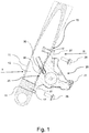
- FIGS 1 and 2 show a load-bearing element 10 of a bicycle, in particular an arm of a front fork.
- the load-bearing element 10 has a hollow structure and comprises a peripheral wall 11 that surrounds and encloses an inner cavity 12 .
- the load-bearing element 10 comprises a fixing area 15 , in the position in which mounting of a caliper group of a disc brake is provided for. At this fixing area 15, an opening 16 is formed in the peripheral wall 11 of the load-bearing element 10. Mounting holes 17 , in particular two threaded mounting holes 17, are formed in the load-bearing element 10, in the fixing area 15, on opposite sides around the opening 16, so that the opening 16 is positioned between the mounting holes 17.
- a caliper group 20 of a disc brake is mounted on the load-bearing element 10.
- the caliper group 20 comprises a caliper body 21 inside which at least one pair of jaws 22 are mounted, moveable towards one another and provided with respective friction pads 23 , adapted for engaging with a brake disc.
- the caliper body 21 has a fixing side 25 , intended to face towards the load-bearing element 10 when the caliper group 20 is mounted on it, as shown in figure 1 .
- the hydraulic system comprises a hydraulic connector 30 , adapted to be connected to a tube T for supplying pressurized fluid; the hydraulic connector 30 is positioned at the fixing side 25 of the caliper body 21, in a recess 31 .
- the caliper body 21 comprises at least two mounting holes 27 for receiving respective mounting screws 28 of the caliper body 21 at the load-bearing element 10.
- the mounting holes 27 are formed at the fixing side 25 on opposite sides around the hydraulic connector 30, so that the hydraulic connector 30 is positioned between the mounting holes 27.
- the mounting holes 27 on the caliper body 21 are at the mounting holes 17 on the load-bearing element 10, so that the mounting screws 28 can pass through the mounting holes 27 and engage in the mounting holes 17.
- the fixing side 25 is configured so as to substantially totally rest on the load-bearing element 10, when fixed to it.
- the hydraulic connector 30 is oriented substantially inclined at 45° with respect to the fixing side 25, and - when the caliper group 20 is mounted on the load-bearing element 10, as shown in figure 1a - faces the opening 16 formed on the load-bearing element 10.
- the tube T for supplying pressurized fluid (possibly and preferably already connected to the brake control) is arranged on the bicycle, inserted inside the load-bearing element 10 and poking out from the opening 16. Thereafter, the tube T is connected to the fitting 32 and the fitting 32 is connected to the hydraulic connector 30 of the caliper group 20. The caliper group 20 is then brought up to the load-bearing element 10, at the same time guiding the tube T in the inner cavity 12 of the load-bearing element 10.
- the caliper group 20 is fixed to the load-bearing element 10, through the mounting screws 28 (inserted in the mounting holes 27 in the caliper body 21 and screwed into the threaded mounting holes 17 in the load-bearing element 10) and the tube T is connected to every other hydraulic component of the bicycle, typically to a brake control group.
- mounting can provide for the tube T for supplying pressurized fluid (not yet connected to the brake control) to be first connected to the fitting 32. Thereafter, the tube T is inserted into the opening 16 in the load-bearing element 10 and the fitting 32 is connected to the hydraulic connector 30 of the caliper group 20. The caliper group 20 is then brought up to the load-bearing element 10, at the same time guiding the tube T in the inner cavity 12 of the load-bearing element 10. At this point, the caliper group 20 is fixed to the load-bearing element 10, through the mounting screws 28 and the tube T is connected to every other hydraulic component of the bicycle, typically to the brake control group.
- the tube T is totally inside the load-bearing element 10, not visible from the outside, in a protected and aerodynamically favorable position; this is true even if the caliper group 20 is slightly distanced from the load-bearing element 10. Furthermore, this configuration ensures that the assembly has a cleaner appearance, certainly desirable for a demanding user. Furthermore, the caliper body 21 completely closes the opening 16 in the load-bearing element, preventing undesired elements such as water, humidity and dirt from being able to penetrate into the load-bearing element 20.
- Figures 4 to 6b show other embodiments of the invention. Hereinafter, these embodiments will be described only as far as they differ from the first embodiment shown in figures 1 to 3 .
- the elements of the various embodiments of the invention that are substantially the same as those of the first embodiment will not be described in general and in the figures they will be marked with the same reference numerals used for the first embodiment.
- the second embodiment also refers to a front disc brake and therefore the load-bearing element 10 is once again an arm of a front fork, equipped with the same features described for the first embodiment of the invention.
- the caliper group differs from the caliper group 20 of the first embodiment of the invention for a different hydraulic connector, indicated with 330 , which is oriented substantially perpendicular to the fixing side 25.
- a connector 330 is sealably associated with a fitting 332 , which has an angled shape, with a first and a second portion 333 and 334 , angled by about 90° with respect to each other.
- the hydraulic connector 330 is positioned at the fixing side 25, protruding from it.
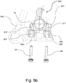
- the third embodiment refers to a rear disc brake; the load-bearing element 510 is a portion of frame close to a rear wheel, otherwise provided with the same features of the load-bearing element 10 of the first embodiment of the invention.
- the caliper group, indicated with 520 differs from the caliper group 20 of the first embodiment of the invention for a different hydraulic connector, indicated with 530 , which substantially protrudes from the fixing side 525 of the caliper body 521 , so as to be inserted in the opening 16 of the load-bearing element 510, when the caliper group 520 is mounted on it.
- the fourth embodiment refers to a rear disc brake; the load-bearing element 610 is a portion of frame close to a rear wheel, otherwise provided with the same features of the load-bearing element 10 of the first embodiment of the invention.
- the caliper group differs from the caliper group 20 of the first embodiment of the invention for a different hydraulic connector, indicated with 630 , which is oriented substantially perpendicular to the fixing side 625.
- a fitting 632 which has an angled shape, with a first and a second portion 633 and 634 , angled by about 90° with respect to each other.
Landscapes
- Engineering & Computer Science (AREA)
- Mechanical Engineering (AREA)
- General Engineering & Computer Science (AREA)
- Transportation (AREA)
- Braking Arrangements (AREA)
- Valves And Accessory Devices For Braking Systems (AREA)
Abstract
Description
- The present invention relates to bicycles with hydraulically-controlled disc brakes. More specifically, the invention relates to a caliper group of a disc brake intended to be mounted on a load-bearing element of a bicycle.
- In high-performance bicycles, in particular but not exclusively in racing bicycles, hydraulically-controlled disc brakes have been widely used for some time, said disc brakes being very popular because they are capable of ensuring a high braking power. These brakes provide for a brake disc mounted on a wheel of the bicycle and rotating as a unit with it and a caliper group mounted on a load-bearing element of the bicycle and active on the disc. The caliper group also comprises a caliper body, inside which at least one pair of jaws is mounted, moveable towards one another and provided with respective friction pads for engaging with the brake disc on opposite sides thereof; a hydraulic system is provided for in the caliper body to control the jaws. The hydraulic system of the caliper body must be supplied with pressurized fluid (generally oil) and consequently the bicycle must be equipped with a tube for supplying pressurized fluid and with a hydraulic brake control to control the supply of pressurized fluid in the tube.
- The arrangement of the tube on the bicycle can provide for the tube to be partially housed inside the load-bearing elements of the bicycle, such as the handlebars, the fork and the frame.
- The tube and the relative fittings can lead to a worsening of the aerodynamic characteristics of the bicycle; such worsening can be particularly unwanted in the case of racing bicycles, where the greatest care is applied to each detail that can improve performance. Furthermore, a tube housed inside the load-bearing elements of the bicycle is protected from bumps and does not risk becoming tangled with foreign bodies that can be located very close to the bicycle when in motion. Finally, a tube housed internally is not visible and therefore does not disturb the aesthetics of the bicycle.
-
US 2015/0001014 discloses a caliper group that is mounted on the load-bearing element of the bicycle right at an opening from which the tube for supplying pressurized fluid comes out, through a base member. The base member acts as a mechanical interface between the caliper group and the load-bearing element of the bicycle: on one side, indeed, it is shaped so as to close the opening on the load-bearing element, whereas on the other side it is adapted for allowing the fixing of the caliper group. - This solution allows the tube for supplying pressurized fluid to be completely hidden inside the load-bearing element, thus improving the aerodynamics.
- The Applicant has however realized that the vibrations that are produced while the bicycle is travelling on the road can cause a loosening of the screws with which the caliper group is fixed to the base member and/or of the screws with which the base member is fixed to the load-bearing element. In both cases it is necessary to retighten the loosened screws; in the second case, furthermore, in order to be able to tighten the screws it is necessary to first dismount the caliper group from the base member, in order to be able to gain access to the loosened screws. Then a relatively long and complex intervention is necessary, which - if it needs to be carried out during a race - would unacceptably penalize the cyclist.
- The present invention therefore refers to a caliper group according to claim 1, as well as to a method for mounting a caliper group according to claim 9 and to a bicycle according to
claim 12. Preferred features are given in the dependent claims. - More specifically, according to a first aspect of the invention the caliper group comprises a caliper body, at least one pair of jaws moveable towards one another and provided with respective friction pads adapted for engaging with a brake disc, a hydraulic system for controlling the jaws; the caliper body has a fixing side, intended to face towards the load-bearing element when the caliper group is mounted on it; the hydraulic system comprises a hydraulic connector adapted for being connected to a tube for supplying pressurized fluid. The fixing side is configured so as to substantially totally rest directly on the load-bearing element, when fixed to it, and the hydraulic connector is positioned at the fixing side of the caliper body.
- This configuration of the caliper body makes it possible to house the tube entirely in the load-bearing element of the bicycle, without having to take it out near to the caliper body in order to be able to connect it to the hydraulic connector. The tube and the connector are thus not in an exposed position, but rather are protected by the load-bearing element and by the caliper body itself. This positioning favors the aerodynamics of the bicycle and at the same time ensures excellent protection of the tube with respect to possible bumps. Furthermore, the configuration of the fixing side allows complete closure of the opening on the load-bearing element, preventing dirt and humidity from being able to penetrate inside while the bicycle is in motion. Furthermore, if the vibrations generated while the bicycle is in motion should lead to loosening of the means with which the caliper body is fixed to the load-bearing element, they can easily be retightened, without having to dismount the caliper group to do so.
- In a preferred embodiment, the hydraulic connector is positioned in a recess formed in the caliper body, at the fixing side. This embodiment is advantageous in the case in which the load-bearing element is small in size; in this way, indeed, after its mounting, the connector - relatively bulky with respect to the tube - stays outside the load-bearing element and just the tube can be made to pass inside the load-bearing element.
- In another preferred embodiment, the hydraulic connector protrudes from the caliper body, at the fixing side. This embodiment is advantageous to reduce the size of the caliper body to the minimum, even if of course it requires that the load-bearing element be of sufficiently large size to also receive the connector; indeed, after its mounting, the connector - relatively bulky - stays received in the load-bearing element.
- Preferably, the caliper group comprises mounting screws for mounting the caliper body on the load-bearing element.
- Preferably, the caliper body comprises, at the fixing side, at least two mounting holes for receiving the mounting screws, and the hydraulic connector is positioned between the two mounting holes. This configuration allows the caliper body to be fixed to the load-bearing element in a balanced manner with respect to the position of the connector and of the tube; it is thus ensured that there is better tightening of the caliper body on the load-bearing element and thus better protection of the connector and of the tube.
- In a preferred embodiment, the hydraulic connector is oriented substantially perpendicular to the fixing side. This configuration reduces the space necessary for the passage of the connector with the tube through the wall of the load-bearing element to the minimum and thus allows the size of the opening in such an element to be reduced.
- In another preferred embodiment, the hydraulic connector is oriented substantially inclined at 45° with respect to the fixing side. This configuration makes it easier to insert the connector with the tube in the load-bearing element, through the opening formed in the wall of the load-bearing element.
- Preferably, the hydraulic connector is associated with a fitting, removably mounted on the hydraulic connector. In this way, the connection of the tube to the connector can be simplified; indeed, it is possible to first connect the tube to only the fitting, which is easy for the operator to handle since it is separate from the caliper body, and then connect the fitting to the hydraulic connector.
- In a second aspect thereof, the invention provides for a method for mounting a caliper group according to the first aspect of the invention on a load-bearing element of a bicycle; according to this method, a tube for supplying pressurized fluid is connected to the hydraulic connector of the caliper group before the caliper group is brought up to and then fixed to the load-bearing element.
- In this way, the tube is adequately protected and mounting of the caliper group is simplified.
- Preferably, the method comprises the steps, in order, of:
- inserting the tube in the load-bearing element and making it poke out from the opening,
- connecting the tube to the hydraulic connector of the caliper group,
- bringing the caliper group up to the load-bearing element at the same time guiding the tube in the cavity of the load-bearing element,
- fixing the caliper group to the load-bearing element.
- Alternatively, the method comprises the steps, in order, of:
- connecting the tube to the hydraulic connector of the caliper group,
- inserting the tube in the opening in the load-bearing element,
- bringing the caliper group up to the load-bearing element at the same time guiding the tube in the cavity of the load-bearing element,
- fixing the caliper group to the load-bearing element,
- connecting the tube to every other hydraulic component of the bicycle.
- In a third aspect thereof, the invention relates to a bicycle comprising a load-bearing element, a brake disc mounted so as to rotate as a unit with a wheel of the bicycle and at least one caliper group according to the second aspect of the invention, mounted on the load-bearing element and active on the brake disc.
- Further features and advantages of the invention will become clearer from the following description of some preferred embodiments thereof, made with reference to the attached drawings. In such drawings:
-
figure 1 is a section view of a load-bearing element and of a caliper group according to a first embodiment of the invention, referring to a front disc brake; -
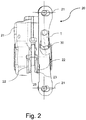
figure 2 is a view of the caliper group offigure 1 separated from the load-bearing element, taken according to the arrow II offig. 1 ; -
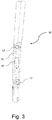
figure 3 is a view of the load-bearing element shown infig. 1 , taken according to the arrow III offig.1 -
figure 4 is a section view of a load-bearing element and of a caliper group according to a second embodiment of the invention, referring to a front disc brake; -
figure 5a is a section view of a load-bearing element and of a caliper group according to a third embodiment of the invention, referring to a rear disc brake; -
figure 5b is a section view according to a different plane of the load-bearing element and of the caliper group offigure 5a ; -
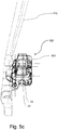
figure 5c is a view from above of the caliper group and of the load-bearing element shown infigs. 5a and5b ; -
figure 6a is a section view of a load-bearing element and of a caliper group according to a fourth embodiment of the invention, referring to a rear disc brake; -
figure 6b is a section view according to a different plane of the load-bearing element and of the caliper group offigure 6a . -
Figures 1 and2 show a load-bearingelement 10 of a bicycle, in particular an arm of a front fork. The load-bearing element 10 has a hollow structure and comprises aperipheral wall 11 that surrounds and encloses aninner cavity 12. - The load-
bearing element 10 comprises a fixingarea 15, in the position in which mounting of a caliper group of a disc brake is provided for. At this fixingarea 15, anopening 16 is formed in theperipheral wall 11 of the load-bearing element 10. Mountingholes 17, in particular two threaded mountingholes 17, are formed in the load-bearing element 10, in the fixingarea 15, on opposite sides around theopening 16, so that theopening 16 is positioned between the mounting holes 17. - As can be seen in
figures 1a and 1b , at the fixingarea 15, acaliper group 20 of a disc brake is mounted on the load-bearing element 10. Thecaliper group 20 comprises acaliper body 21 inside which at least one pair ofjaws 22 are mounted, moveable towards one another and provided withrespective friction pads 23, adapted for engaging with a brake disc. Thecaliper body 21 has a fixingside 25, intended to face towards the load-bearing element 10 when thecaliper group 20 is mounted on it, as shown infigure 1 . - Inside the
caliper body 21 there is a hydraulic system for controlling thejaws 22; the hydraulic system comprises ahydraulic connector 30, adapted to be connected to a tube T for supplying pressurized fluid; thehydraulic connector 30 is positioned at the fixingside 25 of thecaliper body 21, in a recess 31. - The
caliper body 21 comprises at least two mountingholes 27 for receiving respective mountingscrews 28 of thecaliper body 21 at the load-bearing element 10. The mounting holes 27 are formed at the fixingside 25 on opposite sides around thehydraulic connector 30, so that thehydraulic connector 30 is positioned between the mounting holes 27. When thecaliper group 20 is mounted on the load-bearing element 10 (as shown infigure 1 ), the mountingholes 27 on thecaliper body 21 are at the mounting holes 17 on the load-bearing element 10, so that the mountingscrews 28 can pass through the mountingholes 27 and engage in the mounting holes 17. - The fixing
side 25 is configured so as to substantially totally rest on the load-bearing element 10, when fixed to it. - The
hydraulic connector 30 is oriented substantially inclined at 45° with respect to the fixingside 25, and - when thecaliper group 20 is mounted on the load-bearing element 10, as shown infigure 1a - faces theopening 16 formed on the load-bearing element 10. - Mounting of the
caliper group 20 on the load-bearing element 10 takes place in the following way. - First, the tube T for supplying pressurized fluid (possibly and preferably already connected to the brake control) is arranged on the bicycle, inserted inside the load-
bearing element 10 and poking out from theopening 16. Thereafter, the tube T is connected to the fitting 32 and the fitting 32 is connected to thehydraulic connector 30 of thecaliper group 20. Thecaliper group 20 is then brought up to the load-bearing element 10, at the same time guiding the tube T in theinner cavity 12 of the load-bearing element 10. At this point, thecaliper group 20 is fixed to the load-bearing element 10, through the mounting screws 28 (inserted in the mountingholes 27 in thecaliper body 21 and screwed into the threaded mountingholes 17 in the load-bearing element 10) and the tube T is connected to every other hydraulic component of the bicycle, typically to a brake control group. - Alternatively, mounting can provide for the tube T for supplying pressurized fluid (not yet connected to the brake control) to be first connected to the fitting 32. Thereafter, the tube T is inserted into the
opening 16 in the load-bearing element 10 and the fitting 32 is connected to thehydraulic connector 30 of thecaliper group 20. Thecaliper group 20 is then brought up to the load-bearing element 10, at the same time guiding the tube T in theinner cavity 12 of the load-bearing element 10. At this point, thecaliper group 20 is fixed to the load-bearing element 10, through the mountingscrews 28 and the tube T is connected to every other hydraulic component of the bicycle, typically to the brake control group. - Once mounting is complete, the tube T is totally inside the load-
bearing element 10, not visible from the outside, in a protected and aerodynamically favorable position; this is true even if thecaliper group 20 is slightly distanced from the load-bearing element 10. Furthermore, this configuration ensures that the assembly has a cleaner appearance, certainly desirable for a demanding user. Furthermore, thecaliper body 21 completely closes theopening 16 in the load-bearing element, preventing undesired elements such as water, humidity and dirt from being able to penetrate into the load-bearing element 20. -
Figures 4 to 6b show other embodiments of the invention. Hereinafter, these embodiments will be described only as far as they differ from the first embodiment shown infigures 1 to 3 . The elements of the various embodiments of the invention that are substantially the same as those of the first embodiment will not be described in general and in the figures they will be marked with the same reference numerals used for the first embodiment. - The second embodiment, shown in
figure 4 , also refers to a front disc brake and therefore the load-bearing element 10 is once again an arm of a front fork, equipped with the same features described for the first embodiment of the invention. - The caliper group, on the other hand, indicated with 320, differs from the
caliper group 20 of the first embodiment of the invention for a different hydraulic connector, indicated with 330, which is oriented substantially perpendicular to the fixingside 25. Such aconnector 330 is sealably associated with a fitting 332, which has an angled shape, with a first and asecond portion - The
hydraulic connector 330 is positioned at the fixingside 25, protruding from it. - Mounting of the
caliper group 320 on the load-bearing element 10 takes place in the same way as that of thecaliper group 20. - The third embodiment, shown in
figures 5a ,5b and5c , refers to a rear disc brake; the load-bearing element 510 is a portion of frame close to a rear wheel, otherwise provided with the same features of the load-bearing element 10 of the first embodiment of the invention. - The caliper group, indicated with 520, differs from the
caliper group 20 of the first embodiment of the invention for a different hydraulic connector, indicated with 530, which substantially protrudes from the fixingside 525 of thecaliper body 521, so as to be inserted in theopening 16 of the load-bearing element 510, when thecaliper group 520 is mounted on it. - Mounting of the
caliper group 520 on the load-bearing element 510 takes place in a way not very dissimilar from that of thecaliper group 520. One difference is that the fixing screws 28 are inserted in theholes 527 in the load-bearing element 510 and are screwed into the fixingholes 517 in the caliper body 520 (and not vice-versa, as provided for in the first two embodiments of the invention). - The fourth embodiment, shown in
figures 6a and6b , refers to a rear disc brake; the load-bearing element 610 is a portion of frame close to a rear wheel, otherwise provided with the same features of the load-bearing element 10 of the first embodiment of the invention. - The caliper group, indicated with 620, differs from the
caliper group 20 of the first embodiment of the invention for a different hydraulic connector, indicated with 630, which is oriented substantially perpendicular to the fixingside 625. Similarly to the second embodiment shown infig. 4 , there is a fitting 632, which has an angled shape, with a first and asecond portion - Mounting of the
caliper group 620 on the load-bearing element 610 takes place in the same way as that of thecaliper group 20, except that the fixing screws 28 are inserted in theholes 627 in the load-bearing element 610 and are screwed into the fixingholes 617 in the caliper body 620 (similarly to the third embodiment of the invention). - Of course, those skilled in the art will understand that the features of the invention, described with reference to the preferred embodiments shown in the figures, can be combined with each other in a different manner, encompassed by what is defined by the claims.
Claims (12)
- Caliper group (20; 320; 520; 620) of a disc brake intended to be mounted on a load-bearing element (10; 510; 610) of a bicycle, comprising a caliper body (21; 321; 521; 621), at least one pair of jaws (22) moveable towards one another and provided with respective friction pads (23) adapted for engagement with a brake disc, a hydraulic system for controlling the jaws (22), wherein the caliper body (21; 321; 521; 621) has a fixing side (25; 525; 625), intended to face towards the load-bearing element (10; 510; 610) when the caliper group (20; 320; 520; 620) is mounted thereon, and wherein the hydraulic system comprises a hydraulic connector (30; 330; 530; 630) adapted for being connected to a tube (T) for supplying pressurized fluid, characterized in that the fixing side (25; 525; 625) is configured so as to substantially totally rest directly on the load-bearing element (510; 610), when fixed thereto, the hydraulic connector (30; 330; 530; 630) being positioned at the fixing side (25; 525; 625) of the caliper body (21; 321; 521; 621).
- Caliper group according to claim 1, wherein the hydraulic connector (30; 330) is positioned in a recess (31) formed in the caliper body (21; 321), at the fixing side (25).
- Caliper group according to claim 1, wherein the hydraulic connector (530; 630) protrudes from the caliper body (521; 621), at the fixing side (25; 525; 625).
- Caliper group according to any of the previous claims, comprising mounting screws (28) for mounting the caliper body (21; 321; 521; 621) on the load-bearing element (10; 510; 610).
- Caliper group according to claim 4, wherein the caliper body (21; 321; 521; 621) comprises, at the fixing side (25; 525; 625), at least two mounting holes (27; 527; 627) for receiving the mounting screws (28), and wherein the hydraulic connector (30; 330; 530; 630) is positioned between the two mounting holes (27; 527; 627).
- Caliper group according to any of the previous claims, wherein the hydraulic connector (330; 630) is oriented substantially perpendicular to the fixing side (25; 625).
- Caliper group according to any of claims 1 to 5, wherein the hydraulic connector (30; 530) is oriented substantially inclined at 45° with respect to the fixing side (25; 525).
- Caliper group according to any of the previous claims, wherein the hydraulic connector (30; 330; 630) is associated with a fitting (32; 332; 632), removably mounted on the hydraulic connector (30; 330; 630).
- Method for mounting a caliper group (20; 320; 520; 620) according to any of claims 1 to 8 on a load-bearing element (10; 510; 610) of a bicycle, wherein a tube (T) for supplying pressurized fluid is connected to the hydraulic connector (30; 330; 530; 630) of the caliper group (20; 320; 520; 620) before the caliper group (20; 320; 520; 620) is brought up to and then fixed to the load-bearing element (10; 510; 610).
- Method according to claim 9, comprising the steps, in order, of:- inserting the tube (T) into the load-bearing element (10; 510; 610) and making it come out from the opening (16),- connecting the tube (T) to the hydraulic connector (30; 330; 530; 630) of the caliper group (20; 320; 520; 620),- bringing the caliper group (20; 320; 520; 620) up to the load-bearing element (10; 510; 610) at the same time guiding the tube (T) in the cavity (12) of the load-bearing element (10; 510; 610),- fixing the caliper group (20; 320; 520; 620) to the load-bearing element (10; 510; 610).
- Method according to claim 9, comprising the steps, in order, of:- connecting the tube (T) to the hydraulic connector (30; 330; 530; 630) of the caliper group (20; 320; 520; 620),- inserting the tube (T) into the opening (16) in the load-bearing element (10; 510; 610),- bringing the caliper group (20; 320; 520; 620) up to the load-bearing element (10; 510; 610) at the same time guiding the tube (T) in the cavity (12) of the load-bearing element (10; 510; 610),- fixing the caliper group (20; 320; 520; 620) to the load-bearing element (10; 510; 610),- connecting the tube (T) to every other hydraulic component of the bicycle.
- Bicycle comprising a load-bearing element (10; 510; 610), a brake disc mounted so as to rotate as a unit with a wheel of the bicycle and at least one caliper group (20; 320; 520; 620) according to any of claims 1 to 8, mounted on the load-bearing element (10; 510; 610) and active on the brake disc.
Applications Claiming Priority (1)
| Application Number | Priority Date | Filing Date | Title |
|---|---|---|---|
| ITUA2016A001804A ITUA20161804A1 (en) | 2016-03-18 | 2016-03-18 | Caliper assembly of a bicycle disc brake and method for mounting a caliper assembly on a bicycle carrier |
Publications (1)
| Publication Number | Publication Date |
|---|---|
| EP3219597A1 true EP3219597A1 (en) | 2017-09-20 |
Family
ID=56203803
Family Applications (1)
| Application Number | Title | Priority Date | Filing Date |
|---|---|---|---|
| EP17160130.5A Withdrawn EP3219597A1 (en) | 2016-03-18 | 2017-03-09 | Caliper group of a disc brake for a bicycle and method for mounting a caliper group on a load-bearing element of a bicycle |
Country Status (7)
| Country | Link |
|---|---|
| US (1) | US10442493B2 (en) |
| EP (1) | EP3219597A1 (en) |
| JP (1) | JP6893101B2 (en) |
| CN (1) | CN107416109A (en) |
| DE (1) | DE202017007123U1 (en) |
| IT (1) | ITUA20161804A1 (en) |
| TW (1) | TWI708705B (en) |
Cited By (1)
| Publication number | Priority date | Publication date | Assignee | Title |
|---|---|---|---|---|
| DE102018117504A1 (en) | 2018-07-19 | 2020-01-23 | Rose Bikes Gmbh | bicycle |
Families Citing this family (4)
| Publication number | Priority date | Publication date | Assignee | Title |
|---|---|---|---|---|
| US10189536B2 (en) * | 2017-03-15 | 2019-01-29 | Shimano Inc. | Bicycle disc brake caliper |
| US11926390B2 (en) * | 2022-01-17 | 2024-03-12 | Sram, Llc | Flat mount brake caliper for bicycle |
| EP4339086B1 (en) * | 2022-09-14 | 2025-11-05 | Accell Group N.V. | Bicycle frame with brake mounting device for mounting various brake caliper adapters and brake mounting device |
| GB2634886A (en) * | 2023-10-23 | 2025-04-30 | J Laverack Bicycles Ltd | Brake and steering assemblies |
Citations (5)
| Publication number | Priority date | Publication date | Assignee | Title |
|---|---|---|---|---|
| DE102014208317A1 (en) * | 2013-06-28 | 2014-12-31 | Shimano Inc. | Disc brake caliper and basic component |
| US20150001014A1 (en) | 2013-06-28 | 2015-01-01 | Shimano Inc. | Bicycle brake caliper assembly |
| CN104760652A (en) * | 2015-02-27 | 2015-07-08 | 彦豪金属工业股份有限公司 | Bicycle brake oil tube concealing structure |
| US20150210347A1 (en) * | 2014-01-29 | 2015-07-30 | Giant Manufacturing Co., Ltd. | Hidden hydraulic structure of bike disc brake |
| CN104986273A (en) * | 2015-03-19 | 2015-10-21 | 彦豪金属工业股份有限公司 | Front fork structure of bicycle |
Family Cites Families (8)
| Publication number | Priority date | Publication date | Assignee | Title |
|---|---|---|---|---|
| US6148964A (en) * | 1999-05-11 | 2000-11-21 | Huang; Bill | Front disk brake for a bicycle |
| US7478707B2 (en) * | 2007-06-14 | 2009-01-20 | Shimano Inc. | Bicycle disc brake device |
| CN201186724Y (en) * | 2007-12-27 | 2009-01-28 | 彦豪金属工业股份有限公司 | Adjustable oil pumping device for bicycle hydraulic brake system |
| CN101468705B (en) * | 2007-12-27 | 2012-05-09 | 彦豪金属工业股份有限公司 | Concealed Oil Pumping Device of Bicycle Hydraulic Brake |
| US9347505B2 (en) * | 2014-01-30 | 2016-05-24 | Shimano Inc. | Disc brake caliper and base member |
| US9533733B2 (en) * | 2013-06-28 | 2017-01-03 | Shimano Inc. | Disc brake caliper and disc brake caliper assembly |
| US9309938B2 (en) * | 2014-04-23 | 2016-04-12 | Shimano Inc. | Bicycle brake caliper assembly |
| US9688348B2 (en) * | 2014-12-15 | 2017-06-27 | Shimano Inc. | Hydraulic hose fitting and hydraulic device |
-
2016
- 2016-03-18 IT ITUA2016A001804A patent/ITUA20161804A1/en unknown
-
2017
- 2017-03-09 EP EP17160130.5A patent/EP3219597A1/en not_active Withdrawn
- 2017-03-09 DE DE202017007123.1U patent/DE202017007123U1/en active Active
- 2017-03-16 JP JP2017050759A patent/JP6893101B2/en active Active
- 2017-03-16 TW TW106108664A patent/TWI708705B/en active
- 2017-03-17 US US15/461,656 patent/US10442493B2/en active Active
- 2017-03-20 CN CN201710164999.7A patent/CN107416109A/en active Pending
Patent Citations (5)
| Publication number | Priority date | Publication date | Assignee | Title |
|---|---|---|---|---|
| DE102014208317A1 (en) * | 2013-06-28 | 2014-12-31 | Shimano Inc. | Disc brake caliper and basic component |
| US20150001014A1 (en) | 2013-06-28 | 2015-01-01 | Shimano Inc. | Bicycle brake caliper assembly |
| US20150210347A1 (en) * | 2014-01-29 | 2015-07-30 | Giant Manufacturing Co., Ltd. | Hidden hydraulic structure of bike disc brake |
| CN104760652A (en) * | 2015-02-27 | 2015-07-08 | 彦豪金属工业股份有限公司 | Bicycle brake oil tube concealing structure |
| CN104986273A (en) * | 2015-03-19 | 2015-10-21 | 彦豪金属工业股份有限公司 | Front fork structure of bicycle |
Cited By (1)
| Publication number | Priority date | Publication date | Assignee | Title |
|---|---|---|---|---|
| DE102018117504A1 (en) | 2018-07-19 | 2020-01-23 | Rose Bikes Gmbh | bicycle |
Also Published As
| Publication number | Publication date |
|---|---|
| TW201736185A (en) | 2017-10-16 |
| JP6893101B2 (en) | 2021-06-23 |
| TWI708705B (en) | 2020-11-01 |
| ITUA20161804A1 (en) | 2017-09-18 |
| JP2017194154A (en) | 2017-10-26 |
| US20170267311A1 (en) | 2017-09-21 |
| DE202017007123U1 (en) | 2019-08-26 |
| CN107416109A (en) | 2017-12-01 |
| US10442493B2 (en) | 2019-10-15 |
Similar Documents
| Publication | Publication Date | Title |
|---|---|---|
| US10442493B2 (en) | Caliper group of a disc brake for a bicycle and method for mounting a caliper group on a load-bearing element of a bicycle | |
| US9010792B2 (en) | Torque element for a motor-driven bicycle | |
| US9120522B1 (en) | Bicycle hydraulic operating device and bicycle hydraulic device assembly | |
| US9896150B2 (en) | Bicycle operating device | |
| US8408574B2 (en) | Modular trailing edge for bicycle stem | |
| US8684386B2 (en) | Head tube assembly for a bicycle with cable access routing in an open steerer configuration | |
| US20140252746A1 (en) | Bicycle electronic display and shift lever mount | |
| CN104249791A (en) | Bicycle operating device mounting assembly | |
| US9598137B2 (en) | Bicycle front fork assembly | |
| WO2006077346A3 (en) | Rear fork for bicycle | |
| EP2404796A1 (en) | Motorcycle | |
| US7946395B1 (en) | Front brake of racing bicycle | |
| CN104251272A (en) | Bicycle brake caliper assembly | |
| EP2543579B1 (en) | Head tube assembly for a bicycle with cable access routing in an open steerer configuration | |
| TW201400354A (en) | Bicycle brake assembly | |
| EP3366564A1 (en) | Straddled vehicle | |
| TWI526359B (en) | Bicycle brake arm | |
| CA1064411A (en) | Caliper brakes for cycles and same | |
| JP5948717B1 (en) | Washer, bicycle frame fitted with the washer, and bicycle equipped with them | |
| JP5102768B2 (en) | Bicycle fork with hydraulic brake | |
| EP2546126B1 (en) | A two-wheeled motor vehicle having a chain case | |
| TW201927627A (en) | Operating device assembly and operating device | |
| JP3122166U (en) | Bicycle wheel mounting structure | |
| PH12018050017A1 (en) | Straddled vehicle | |
| EP2383177A1 (en) | Front brake of racing bicycle |
Legal Events
| Date | Code | Title | Description |
|---|---|---|---|
| PUAI | Public reference made under article 153(3) epc to a published international application that has entered the european phase |
Free format text: ORIGINAL CODE: 0009012 |
|
| STAA | Information on the status of an ep patent application or granted ep patent |
Free format text: STATUS: THE APPLICATION HAS BEEN PUBLISHED |
|
| AK | Designated contracting states |
Kind code of ref document: A1 Designated state(s): AL AT BE BG CH CY CZ DE DK EE ES FI FR GB GR HR HU IE IS IT LI LT LU LV MC MK MT NL NO PL PT RO RS SE SI SK SM TR |
|
| AX | Request for extension of the european patent |
Extension state: BA ME |
|
| STAA | Information on the status of an ep patent application or granted ep patent |
Free format text: STATUS: REQUEST FOR EXAMINATION WAS MADE |
|
| 17P | Request for examination filed |
Effective date: 20180320 |
|
| RBV | Designated contracting states (corrected) |
Designated state(s): AL AT BE BG CH CY CZ DE DK EE ES FI FR GB GR HR HU IE IS IT LI LT LU LV MC MK MT NL NO PL PT RO RS SE SI SK SM TR |
|
| STAA | Information on the status of an ep patent application or granted ep patent |
Free format text: STATUS: EXAMINATION IS IN PROGRESS |
|
| 17Q | First examination report despatched |
Effective date: 20181219 |
|
| STAA | Information on the status of an ep patent application or granted ep patent |
Free format text: STATUS: THE APPLICATION IS DEEMED TO BE WITHDRAWN |
|
| 18D | Application deemed to be withdrawn |
Effective date: 20190702 |