EP3219418A1 - Sacrificial core for conglomerated powder removal - Google Patents
Sacrificial core for conglomerated powder removal Download PDFInfo
- Publication number
- EP3219418A1 EP3219418A1 EP17161420.9A EP17161420A EP3219418A1 EP 3219418 A1 EP3219418 A1 EP 3219418A1 EP 17161420 A EP17161420 A EP 17161420A EP 3219418 A1 EP3219418 A1 EP 3219418A1
- Authority
- EP
- European Patent Office
- Prior art keywords
- solid core
- solid
- core
- feature
- shearing
- Prior art date
- Legal status (The legal status is an assumption and is not a legal conclusion. Google has not performed a legal analysis and makes no representation as to the accuracy of the status listed.)
- Granted
Links
Images




Classifications
-
- B—PERFORMING OPERATIONS; TRANSPORTING
- B22—CASTING; POWDER METALLURGY
- B22F—WORKING METALLIC POWDER; MANUFACTURE OF ARTICLES FROM METALLIC POWDER; MAKING METALLIC POWDER; APPARATUS OR DEVICES SPECIALLY ADAPTED FOR METALLIC POWDER
- B22F3/00—Manufacture of workpieces or articles from metallic powder characterised by the manner of compacting or sintering; Apparatus specially adapted therefor ; Presses and furnaces
- B22F3/24—After-treatment of workpieces or articles
-
- B—PERFORMING OPERATIONS; TRANSPORTING
- B22—CASTING; POWDER METALLURGY
- B22F—WORKING METALLIC POWDER; MANUFACTURE OF ARTICLES FROM METALLIC POWDER; MAKING METALLIC POWDER; APPARATUS OR DEVICES SPECIALLY ADAPTED FOR METALLIC POWDER
- B22F10/00—Additive manufacturing of workpieces or articles from metallic powder
- B22F10/20—Direct sintering or melting
- B22F10/28—Powder bed fusion, e.g. selective laser melting [SLM] or electron beam melting [EBM]
-
- B—PERFORMING OPERATIONS; TRANSPORTING
- B22—CASTING; POWDER METALLURGY
- B22F—WORKING METALLIC POWDER; MANUFACTURE OF ARTICLES FROM METALLIC POWDER; MAKING METALLIC POWDER; APPARATUS OR DEVICES SPECIALLY ADAPTED FOR METALLIC POWDER
- B22F10/00—Additive manufacturing of workpieces or articles from metallic powder
- B22F10/40—Structures for supporting workpieces or articles during manufacture and removed afterwards
- B22F10/47—Structures for supporting workpieces or articles during manufacture and removed afterwards characterised by structural features
-
- B—PERFORMING OPERATIONS; TRANSPORTING
- B22—CASTING; POWDER METALLURGY
- B22F—WORKING METALLIC POWDER; MANUFACTURE OF ARTICLES FROM METALLIC POWDER; MAKING METALLIC POWDER; APPARATUS OR DEVICES SPECIALLY ADAPTED FOR METALLIC POWDER
- B22F10/00—Additive manufacturing of workpieces or articles from metallic powder
- B22F10/60—Treatment of workpieces or articles after build-up
- B22F10/66—Treatment of workpieces or articles after build-up by mechanical means
-
- B—PERFORMING OPERATIONS; TRANSPORTING
- B22—CASTING; POWDER METALLURGY
- B22F—WORKING METALLIC POWDER; MANUFACTURE OF ARTICLES FROM METALLIC POWDER; MAKING METALLIC POWDER; APPARATUS OR DEVICES SPECIALLY ADAPTED FOR METALLIC POWDER
- B22F5/00—Manufacture of workpieces or articles from metallic powder characterised by the special shape of the product
- B22F5/10—Manufacture of workpieces or articles from metallic powder characterised by the special shape of the product of articles with cavities or holes, not otherwise provided for in the preceding subgroups
-
- B—PERFORMING OPERATIONS; TRANSPORTING
- B22—CASTING; POWDER METALLURGY
- B22F—WORKING METALLIC POWDER; MANUFACTURE OF ARTICLES FROM METALLIC POWDER; MAKING METALLIC POWDER; APPARATUS OR DEVICES SPECIALLY ADAPTED FOR METALLIC POWDER
- B22F3/00—Manufacture of workpieces or articles from metallic powder characterised by the manner of compacting or sintering; Apparatus specially adapted therefor ; Presses and furnaces
- B22F3/24—After-treatment of workpieces or articles
- B22F2003/247—Removing material: carving, cleaning, grinding, hobbing, honing, lapping, polishing, milling, shaving, skiving, turning the surface
-
- B—PERFORMING OPERATIONS; TRANSPORTING
- B22—CASTING; POWDER METALLURGY
- B22F—WORKING METALLIC POWDER; MANUFACTURE OF ARTICLES FROM METALLIC POWDER; MAKING METALLIC POWDER; APPARATUS OR DEVICES SPECIALLY ADAPTED FOR METALLIC POWDER
- B22F5/00—Manufacture of workpieces or articles from metallic powder characterised by the special shape of the product
- B22F5/10—Manufacture of workpieces or articles from metallic powder characterised by the special shape of the product of articles with cavities or holes, not otherwise provided for in the preceding subgroups
- B22F2005/103—Cavity made by removal of insert
-
- B—PERFORMING OPERATIONS; TRANSPORTING
- B22—CASTING; POWDER METALLURGY
- B22F—WORKING METALLIC POWDER; MANUFACTURE OF ARTICLES FROM METALLIC POWDER; MAKING METALLIC POWDER; APPARATUS OR DEVICES SPECIALLY ADAPTED FOR METALLIC POWDER
- B22F2999/00—Aspects linked to processes or compositions used in powder metallurgy
-
- Y—GENERAL TAGGING OF NEW TECHNOLOGICAL DEVELOPMENTS; GENERAL TAGGING OF CROSS-SECTIONAL TECHNOLOGIES SPANNING OVER SEVERAL SECTIONS OF THE IPC; TECHNICAL SUBJECTS COVERED BY FORMER USPC CROSS-REFERENCE ART COLLECTIONS [XRACs] AND DIGESTS
- Y02—TECHNOLOGIES OR APPLICATIONS FOR MITIGATION OR ADAPTATION AGAINST CLIMATE CHANGE
- Y02P—CLIMATE CHANGE MITIGATION TECHNOLOGIES IN THE PRODUCTION OR PROCESSING OF GOODS
- Y02P10/00—Technologies related to metal processing
- Y02P10/25—Process efficiency
Definitions
- the present invention relates generally to additive manufacturing, and more particularly to additively manufacturing a part with an internal passage.
- Additive manufacturing is an established but growing technology that includes layerwise construction of articles from thin layers of feed material. Additive manufacturing can involve applying liquid or particulate material to a workstage, then sintering, curing, melting, etc. to create a layer. The process is repeated up to several thousand times or more to construct the desired finished component or article.
- EBM electron beam melting
- EBM electron beam melting
- electron beam powder bed additive manufacturing energy input into a metal powder bed during the build process will melt a cross section of a solid part.
- the electron beam energy will also tend to cause metal powder inside of the internal passages to become stuck together during the build process.
- the entire layer of powdered material is semi-sintered (synonymous with partially sintered) to reduce the effects of powdered material scattering when the negatively charged electron beam is applied to the powder bed. Once the part is built, the semi-sintered layers of powdered material remain inside internal passages of the part.
- the extra semi-sintered metal powder inside the internal passages therefore must be removed by some mechanical, abrasive, chemical, or vibratory method to retrieve only the solid part.
- An example strategy to remove excess conglomerated, or semi-sintered, powder from the part can include accelerating like powder from a grit blast nozzle to liberate (knock loose) the semi-sintered particles from the part. Accelerated powder can be effective but only to a certain depth limit, e.g., aspect ratio, for removing semi-sintered powder from the internal passages, and only within line-of-sight access from a point exterior to the part.
- conglomerated powder becomes entrapped in the internal passage.
- methods known to directly and quickly remove the conglomerated powder from internal passages One example of a standard practice consists of repeatedly using the accelerated powder blast, combined with mechanically scraping conglomerated power out of the passage.
- a method of making a part including a solid portion with an internal passage includes building the part using an additive manufacturing process that builds the part on a layer-by-layer basis.
- the solid portion of the part is formed.
- a solid core is formed within at least a portion of the internal passage.
- Forming the solid core includes forming an attachment feature and forming a shearing feature. Material that is not fused, either semi-sintered or un-sintered, is positioned between the solid portion and the solid core.
- a force selected from the group consisting of a tensile, compressive, vibratory, and torsional force is applied to the solid core at the attachment feature. The material is then shorn with the shearing feature.
- a method of making a part including a solid portion with an internal passage includes creating a computer file defining the part in layers.
- the part is built using an additive manufacturing process that builds the part on a layer-by-layer basis.
- a solid core is formed within at least a portion of the internal passage.
- the solid core includes a plurality of solid core segments.
- a shearing feature is formed on each of the plurality of solid core segments.
- An attachment feature is formed on the solid core. Material that is not fused, either semi-sintered or un-sintered, is positioned between the solid portion and the solid core. Tooling is engaged with the attachment feature.
- a force selected from the group consisting of a tensile, compressive, vibratory, and torsional force is applied to the solid core.
- the solid core is detached from the part. The material is then shorn with the shearing feature.
- FIG. 1 is a cross-sectional view of an embodiment of additively manufactured part 10 which includes solid core 12, solid portion 14, internal passage 16, and material 18. Material 18 is semi-sintered or un-sintered.
- Solid core 12 includes attachment feature 20 and shearing portion 22.
- Additively manufactured part 10 is built by either EBM or electron beam powder bed additive manufacturing process. As additively manufactured part 10 is built, material 18 is semi-sintered or left un-sintered (i.e., in powder form, without significant inter-particle attachment) within internal passage 16 between solid core 12 and solid portion 14. Throughout the build process, solid core 12 is fused to the same or similar degree as solid portion 14. Once the additive manufacturing process is complete, solid core 12 is formed as a fully-fused solid core and is attached to material 18. Material 18 is positioned within internal passage 16 and is attached to solid portion 14. Additively manufactured part 10 can be built from powdered material such as a nickel superalloy, aluminum alloy, titanium alloy, steel alloy, cobalt alloy, or other suitable metal.
- EBM and electron beam powder bed additive manufacturing processes are primarily described, other additive manufacturing techniques can be employed, such as, for example, direct metal laser sintering (DMLS), laser powder bed fusion, electron beam powder bed fusion, laser powder deposition, electron beam wire, and selective laser sintering, as well as other powder bed methods in general.
- DMLS direct metal laser sintering
- laser powder bed fusion laser powder bed fusion
- electron beam powder bed fusion laser powder deposition
- electron beam wire electron beam wire
- selective laser sintering selective laser sintering
- powder bed methods use a bed of metallic powder that rests on top of a platform to form the layers.
- a heat source such as a laser or electron beam, sinters or fuses the metallic powder over the platform.
- the fused layer becomes the first layer.
- the platform, along with the first layer, lowers and un-fused powder fills in the void over the first layer. That powder is then sintered or fused to form a second layer.
- Powder bed methods work well with metals as well as plastics, polymers, composites and ceramics.
- the apparatus forms each layer with reference to a computer file, or computer aided design ("CAD") data, defining the part in layers.
- the CAD data can relate to a particular cross-section of additively manufactured part 10.
- the CAD data can include geometric data relating to cylindrical core 12A, solid portion 14, internal passage 16, and material 18.
- additively manufactured part 10 can be produced to include to include particular geometries and internal features.
- a single-piece cylindrical core 12A can be produced that requires no further assembly and can be directly built inside of internal passage 16.
- Solid core 12 is a solid core in the sense that solid core 12 is fused to the same degree as additively manufactured part 10.
- solid core 12 has a long, narrow strip shape which can extend along internal passage 16.
- solid core 12 can also include a hollow center, as well as simple and/or complex geometries throughout an interior of solid core 12 such as truss structures or lattice structures.
- Thickness T SC of solid core 12 can be less than 1/10 of diameter D IP of internal passage 16.
- a width of solid core 12, shown as helical diameter D 1 is greater than thickness T SC of solid core 12 but less than diameter D IP of internal passage 16.
- the shape of solid core 12 can vary to include other shapes, sizes, widths, and thicknesses as desired for particular embodiments.
- Solid core 12 includes shearing portion 22 which includes a helix with a radial shape of a circle that is twisted about major axis A m in this embodiment.
- shearing portion 22 can be a helix with a radial shape (i.e., a silhouette perimeter shape projected along major axis A m ) of an oval, square, or triangle, as well as include varying degrees of twist for example.
- a pitch of shearing feature 22 can be constant or can vary along A m and can have any suitable value.
- Attachment feature 20 is formed on solid core 12 during an additive manufacturing build process. Attachment feature 20 is configured to receive tooling for attaching with solid core 12. Attachment feature 20 can include one or more features such as a hole, bore, tongue, groove, receptacle, link, insert, chuck, socket, clamp, or other type of engagement feature configured to engage with tooling such as a hex drive, square drive, or other suitable attachment form factors. Once tooling is engaged to attachment feature 20, at least one of a tensile, compressive, vibratory, or torsional force is applied to solid core 12 at attachment feature 20 to detach solid core 12 from material 18.
- the at least one of a tensile, compressive, vibratory, or torsional force can be applied, for instance, by standard compressive hammer drill, tensile hammer drill, impact hammer, impact wrench, breaker bar, drill, hand tool, and/or through application of vibration. These applied forces can be monotonic or cyclical.
- Solid core 12 is then extracted from additively manufactured part 10. Any remaining material 18 is then removed from internal passage 16 through powder recovery system ("PRS") or abrasive flow techniques.
- PRS techniques include blasting powder at the part to break apart material 18.
- Abrasive flow techniques include flowing a liquid containing abrasive particles through internal passage 16 to remove material 18.
- Forming additively manufactured part 10 with solid core 12 allows for manufacturability of internal passage 16 of additively manufactured part 10 by allowing the removal of material 18 from deep or high aspect ratio passages. Forming additively manufactured part 10 with solid core 12 also allows for better thermal conductivity to the adjacent passage walls, which in turn enables better manufacturability, reduced surface roughness on passage walls, and improved dimensional results in the as-produced state. A smaller amount of support structures will also be required on the interior of internal passage 16, due to solid core 12 being solid which allows for greater thermal conduction than a powder bed alone, which can be a prevalent issue particularly in laser powder bed fusion processes.
- the benefits of using solid core 12 can further include reducing the amount of material 18 to be removed from internal passage 16 due to the void left from solid core 12 after solid core 12 is removed from additively manufactured part 10.
- the void left from solid core 12 allows for less material 18 left in internal passage 16 after the build process (as compared to if a solid core was not used) resulting in less material 18 required to be removed by PRS and/or abrasive flow techniques.
- Use of cylindrical core 12A also allows material 18 to be removed from internal passage due to the increased access to material 18 after cylindrical core 12A is removed. If cylindrical core 12A were not used, for example, material 18 could not all be removed from all portions of internal passage 16 and additively manufactured part 10 would not functioned as desired.
- shearing feature 22 enables solid core 12 to actively remove material 18 from internal passage 16 as solid core 12 is extracted from additively manufactured part 10. Actively removing material 18 during the extraction of solid core 12 reduces an amount of powder removal techniques (e.g., PRS or abrasive flow) that are required to adequately remove the remaining portions of material 18 from internal passage 16 in order to allow additively manufactured part 10 to operate as desired.
- powder removal techniques e.g., PRS or abrasive flow
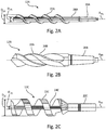
- FIG. 2A is a side view of solid core 12A, shown in isolation.
- Solid core 12A includes attachment feature 20A and shearing feature 22A.
- Shearing feature 22A includes a helical shape which wraps around center element 24A.
- Each of attachment feature 20A, shearing feature 22A, and center element 24A are all integrally formed as a single article during the additive manufacturing build process.
- solid core 12A After solid core 12A is detached from material 18, solid core 12A is rotated about major axis A m of solid core 12A, wherein major axis A m extends through a center of solid core 12A.
- shearing feature 22A shears material 18 from internal passage 16.
- Shearing feature 22A actively removes material 18 from internal passage 16 by coming into contact with material 18 and shearing material 18.
- Shearing feature 22A imparts a localized shearing action on material 18, thereby separating weak inter-particle bonds in material 18, which causes material 18 to be shorn away from internal passage 16.
- shearing feature 22A includes helical diameter D 1A that is approximately twice as large as diameter D 2A of center element 24A. In other embodiments, a value of helical diameter D 1A can fall between the range of D 2A ⁇ D 1A ⁇ a diameter of internal passage 16.
- shearing feature 22A can vary to include other shapes, sizes, widths, and thicknesses as well as varying degrees of twist as desired for particular embodiments.
- shearing portion 22A can be a helix with a radial shape of a circle (shown in FIG. 2A ), oval, square, or triangle, as well as other non-symmetrical shapes for example.
- FIG. 2B is a side view of solid core 12B, shown in isolation.
- Solid core 12B includes attachment feature 20B and shearing feature 22B.
- Shearing feature 22B includes ridges 26B which wrap around solid core 12B.
- Each of attachment feature 20B, shearing feature 22B, and ridges 26B are all integrally formed as a single article during the additive manufacturing build process.
- shearing feature 22B includes two ridges 26B. In other embodiments, quantities of ridges 26B can vary to be more or less than two. In further embodiments, the shape of shearing feature 22B can vary to include other shapes, sizes, widths, and thicknesses as well as varying degrees of twist as desired for particular embodiments. In various embodiments, shearing portion 22B can include a helix with a radial shape of a circle, oval, square, or triangle, as well as other non-symmetrical shapes for example.
- FIG. 2C is a side view of solid core 12C, shown in isolation.
- Solid core 12C includes attachment feature 20C and shearing feature 22C.
- Shearing feature 22C has a helical shape that wraps around center element 24C.
- Each of attachment feature 20C, shearing feature 22C, and center element 24C are all integrally formed as a single article during the additive manufacturing build process.
- shearing feature 22C includes helical diameter D 1C that is approximately five times as large as diameter D 2C of center element 24C. In other embodiments, a value of helical diameter D 1C can fall between the range of D 2C ⁇ D 1C ⁇ a diameter of internal passage 16.
- shearing feature 22C can vary to include other shapes, sizes, widths, and thicknesses as well as varying degrees of twist as desired for particular embodiments.
- shearing portion 22C can be a helix with a radial shape of a circle (shown in FIG. 2C ), oval, square, or triangle, as well as other non-symmetrical shapes for example.
- FIG. 2D is a side view of solid core 12D, shown in isolation.
- Solid core 12D includes attachment feature 20D and shearing feature 22D.
- Shearing feature 22D includes ridge 26D.
- Shearing feature 22D includes a tapered shape that widens away from attachment feature 20D.
- Each of attachment feature 20D and shearing feature 22D are all integrally formed as a single article during the additive manufacturing build process.
- shearing feature 22D shears material 18 from internal passage 16.
- Shearing feature 22D actively removes material 18 from internal passage 16 by coming into contact with material 18 and shearing at least a portion of material 18.
- Shearing feature 22D imparts a localized shearing action on material 18, thereby separating weak inter-particle bonds in material 18, which causes material 18 to be shorn away from internal passage 16.
- ridge 26D cuts into material 18 and shears material 18.
- solid core 12D can be moved in an axial direction and positioned to cut another full revolution of material 18. These steps can be repeated to produce a step-wise cutting process until solid core 12D is completely removed from internal passage 16.
- shearing feature 22D is similar to that of broaching.
- Broaching which includes a toothed tool called a broach, includes removing material from a workpiece with the broach.
- Rotary broaching similar to the described use of solid core 12D above, includes rotating and pressing the rotary broach into the workpiece to cut an axis symmetric shape. With rotary broaching, a cut is completed after a single rotation of the rotary broach which can be more efficient than the drill bit examples provided in FIGS. 2A-2C .
- a shearing feature on solid core can include any other type of cutting, shearing, or manufacturing tool known in the art, to provide a desired shear and/or frictional response between the solid core and material positioned between the multi-segment core and a solid portion of the part.
- Angle ⁇ represents an angle of taper of shearing feature 22D relative to major axis A m of solid core 12D.
- Angle ⁇ extending between plane 30D and major axis A m , can range from 0° to less than 90°.
- the taper angle ⁇ can vary along a length of solid core 12D, or solid core 12D can be curvably tapered, as desired for particular embodiments.
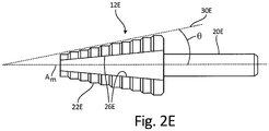
- FIG. 2E is a side view of solid core 12E, shown in isolation.
- Solid core 12E includes attachment feature 20E and shearing feature 22E.
- Shearing feature 22E includes ridge 26E.
- Shearing feature 22E includes a tapered shape that narrows away from attachment feature 20E.
- Each of attachment feature 20E and shearing feature 22E are all integrally formed as a single article during the additive manufacturing build process.
- Angle ⁇ represents an angle of taper of shearing feature 22E relative to major axis A m of solid core 12E.
- Angle ⁇ extending between plane 30E and major axis A m , can range from 0° to less than 90°.
- the taper angle ⁇ can vary along a length of solid core 12E, or solid core 12E can be curvably tapered, as desired for particular embodiments.
- FIG. 3 is a sectional view of an embodiment of additively manufactured part 110 with multi-segment core 112.
- Additively manufactured part 110 includes multi-segment core 112, solid portion 114, internal passage 116, and material 118.
- Multi-segment core 112 includes attachment feature 120, shearing features 122, first core segment 124, and second core segment 126. The location of the section from which FIG. 3 is viewed is located slightly off-center from a center of multi-segment core 112.
- Attachment feature 120 includes first female interlocking feature 128 which receives and connects with first male interlocking feature 130 of first core segment 124.
- First core segment 124 includes second female interlocking feature 132 which receives and connects with second male interlocking feature 134.
- As torsional force F torsional is applied to attachment feature 120 attachment feature 120 breaks from material 118 allowing attachment feature 120 to rotate.
- first female interlocking feature 128 of attachment feature 120 engages with first male interlocking feature 130 of first core segment 124.
- force F torsional is further applied to attachment feature 120, first core segment 124 also breaks from material 118 due to torsional force F torsional being transferred to first core segment 124 from attachment feature 120.
- shearing feature 122 on first core segment 124 engages with material 118 and shears material 118 from internal passage 116.
- Shearing feature 122 on first core segment 124 actively removes material 118 from the portion of internal passage 116 occupied by first core segment 124 by shearing feature 122 coming into contact with material 118 and shearing material 118.
- Shearing feature 122 imparts a localized shearing or abrading action on material 118, thereby separating weak inter-particle bonds in material 118, which causes material 118 to be shorn or scraped away from internal passage 116.
- first core segment 124 is rotated with attachment feature 120
- second female interlocking feature 132 of first core segment 124 engages with second male interlocking feature 134 of second core segment 126.
- second core segment 126 breaks from material 118 due to torsional force F torsional being transferred to second core segment 126 through first core segment 124 from attachment feature 120.
- shearing feature 122 on second core segment 126 engages with material 118 and shears material 118 from internal passage 116.
- Multi-segment core 112 provides the benefit of a staged shear and frictional response between multi-segment core 112 and material 118.
- torsional force F torsional is applied to attachment feature 120
- attachment feature 120 first breaks from material 118 before engaging with first core segment 124.
- attachment feature 120 locks with first core segment 124 causing first core segment 124 to break from material 118.
- first core segment 124 is attached to material 118 only along a length of first core segment 124, an amount of torsional force F torsional required to break first core segment 124 from material 118 is proportional to the length of first core segment 124.
- the amount of torsional force F torsional required to break first core segment 124 from material 118 is less than an amount of torsional force F torsional that would be required to break a core segment with a length longer than first core segment 124 because a longer core segment would have more surface area attached to material 118 thus requiring more torsional force to be applied to break the connection between material 118 and the longer core segment.
- tensile force F tensile is applied to attachment feature 120 to remove multi-segment core 112 from additively manufactured part 110.
- multi-segment core 112 includes attachment feature 120 and two core segments 124 and 126.
- a multi-segment core can include more or less, longer or shorter, or wider or narrower core segments and/or shearing features, to provide a desired shear and/or frictional response between the multi-segment core and material positioned between the multi-segment core and a solid portion of the part.
- multi-segment core 112 can include any or all of the shearing features disclosed in each of the other embodiments included in this disclosure.
- FIG. 4 is a cross-sectional view of multi-segment core 112 taken along line 4-4 of FIG. 3 and FIG. 5 is a cross-sectional view of multi-segment core 112 taken along 5-5 of FIG. 3 .
- First core segment 124 and second core segment 126 interlock with each other such that as first core segment 124 is rotated, the spacing between first core segment 124 and second core segment 126 is reduced, first core segment comes into angular contact with second core segment 126, and torsional force F torsional is transferred from first core segment 124 to second core segment 126.
- first female interlocking feature 128 and first male interlocking feature 130 provides a twist-to-lock feature between first core segment 124 and second core segment 126 whereby application of relative torsional engagement between first core segment 124 and second core segment 126 causes first core segment 124 and second core segment 126 to lock with each other such that first core segment 124 and second core segment 126 can be rotated and pulled together.
- fingers 136 of attachment feature 120 enable angular contact with and transmission of torsional force F torsional to first core segment 124.
- Fingers 138 of first core segment 124 enable angular contact with and transmission of torsional force F torsional to second core segment 126.
- Fingers 136 and 138 include a quarter-circle cross sectional shape.
- First core segment 124 and second core segment 126 can have cut-outs which are shaped to receive the quarter-circle shapes of fingers 136 and 138 respectively.
- fingers 136 and 138 can include more or less, longer or shorter, or wider or narrower shapes and/or cross-sections, to provide a desired torsional response between attachment feature 120, first core segment 124, and second core segment 126.
- FIG. 6 is a cross-sectional view of an embodiment of additively manufactured part 210 which includes solid core 212, solid portion 214, internal passage 216, and material 218.
- Solid core 212 is positioned within internal passage 216 and is located off-center relative to internal passage 216. After solid core 212 is detached from material 218, solid core 212 is rotated about major axis A m of solid core 212, wherein major axis A m extends through a center of solid core 212. As solid core 212 is rotated, shearing feature 222 shears material 218 from internal passage 216. Shearing feature 222 actively removes material 218 from internal passage 216 by coming into contact with material 18 and shearing material 218.
- solid core 212 As solid core 212 is rotated about an axis A m in the illustrated embodiment, solid core 212 is also moved along orbit O within internal passage 216, thereby moving solid core 212 about an epicyclic or planetary path. As solid core 212 moves along orbit O, solid core 212 shears material 218 along the path of orbit O. Solid core 212 can also be extracted from internal passage 216 (e.g., in FIG. 6 , drawn into or out of the page) while being moved along orbit O.
- solid core 212 incorporates a cutting behavior similar to that of a milling cutter, in that the cutting or shearing action of solid core 212 occurs as solid core moves in a radial direction (relative to solid core 212), as opposed to an axially oriented cutting direction of various other types of cutters such as drill bits.
- the shape of orbit O can vary to include other shapes and sizes as desired for particular embodiments.
- orbit O can include a shape of a circle, oval, square, or triangle, for example.
- the shape and size of solid core can also vary.
- solid core 212 can have a small diameter relative to a diameter of internal passage (e.g., diameter of solid core 212 can be less than 1/10 the size of the diameter of internal passage 216).
- Forming solid core 212 along with additively manufactured part 210 also provides the benefit of reducing the number of machining steps typical machining methods would require to remove material 218. For example, in order to create a hole for a milling cutter to be introduced into material 218, an axially cutting drill bit would need to first cut a hole into material 218. The axially cutting drill bit would then need to be removed, before a milling cutter bit could be introduced into the hole created by the axially cutting drill bit. Forming solid core 212 along with additively manufactured part 210 reduces the number of steps because after additively manufactured part 210 is formed, solid core 212 is already positioned within material 218 which obviates the step of axially cutting the hole into material 218.
- FIG. 7 is a cross-sectional view of additively manufactured part 310 which includes multi-segment core 312, solid portion 314, internal passage 316 with bend 332, and material 318.
- Multi-segment core 312 includes first core segment 334A and second core segment 334B.
- First core segment 334A includes attachment feature 320A and shearing feature 322A.
- Second core segment 334B includes attachment feature 320B and shearing feature 322B.
- first core segment 334A and second core segment 334B in additively manufactured part 310 allows for formation and removal of solid cores within an internal passage which includes a non-linear geometry.
- internal passage 316 includes bend 332 and essentially two major portions of passageway.
- first core segment 334A and second core segment 334B are formed to create separation S between first core segment 334A and second core segment 334B.
- first torsional force F torsional is applied to first core segment 334A
- second torsional force F torsional is applied to second core segment 334B.
- compressive, vibratory, or torsional forces can also be applied to either or both of first core segment 334A and second core segment 334B. These applied forces can be monotonic or cyclical.
- Internal passage 316 with bend 332 is an example of an internal passage with more than just a simple linear passageway extending through additively manufactured part 310.
- the illustrated embodiment is shown merely by way of example and not limitation.
- other internal passageways can include longer or shorter, or wider or narrower or bends with different shapes than internal passage 316 with bend 332.
- a multi-segment core can include longer or shorter, or wider or narrower core segments and/or shearing features, to provide a desired shear and/or frictional response between the multi-segment core and the material positioned between the multi-segment core and a solid portion of the part.
- multi-segment core 312 can include any or all of the shearing features disclosed in each of the other embodiments included in this disclosure.
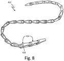
- FIG. 8 is a perspective view multi-segment core 412 shown in isolation, which includes a plurality of links 414. Each link 414 includes shearing feature 416.
- Multi-segment core 412 can be used in any of the preceding embodiments of internal passageways including both linear internal passageways and internal passageways including complex geometries.
- Each link 414 includes features allowing links 414 to pivot relative to each other. As a tensile, compressive, vibratory, and/or torsional force is applied to multi-segment core 412 and as multi-segment core 412 is maneuvered through an internal passage of an additively manufactured part during removal, links 414 to pivot relative to each other to conform to a shape of the internal passage.
- links 414 to conform to the shape of the internal passageway allows for the use of multi-segment core 412 in internal passageways including complex geometries and numerous bends, twists, and turns, while still being able to extract an entire length of multi-segment core 412 by applying at least one of a tensile, compressive, vibratory, or torsional force to multi-segment core 412.
- Shearing feature 416 includes a sharp edge for cutting material in both an axial and radial direction. As shearing feature 416 is drawn across a material in an internal passage along either an axial or radial direction, shearing feature 416 cuts into the material inside of the internal passage. Shearing feature 416 shears away the material in the internal passage by imparting a localized shearing action on the material, thereby separating weak inter-particle bonds in the material, which causes the material to be shorn away from the internal passage.
- shearing features 416 enable multi-segment core 412 to actively remove material from an internal passage as multi-segment core 412 is extracted from an additively manufactured part.
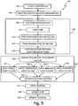
- FIG. 9 is a flowchart of method 500 of additively manufacturing a part with a core, which includes a series of steps to additively manufacture a part.
- the part is formed to include an internal passage extending through at least a portion of the part.
- EBM any other form of additive manufacturing or 3D printing, such as EB powder bed additive manufacturing, direct metal laser sintering (DMLS), laser powder bed fusion, electron beam powder bed fusion, laser powder deposition, electron beam wire, and selective laser sintering, as well as other powder bed methods in general, can be used.
- Step 502 includes creating a computer file defining the part in layers, with the part including an internal passage and a solid portion.
- Step 504 includes selecting an additive manufacturing process to build the part on a layer-by-layer basis, with the additive manufacturing process being either EBM or electron beam powder bed additive manufacturing.
- the part can be built from powdered material such as a nickel superalloy, aluminum alloy, titanium alloy, steel alloy, cobalt alloy, or other suitable metal.
- Step 506 Additively building the part (collectively, Step 506) includes individual steps 508-516.
- Step 508 includes fusing the solid portion of the part.
- Step 510 includes forming a core within at least a portion of the internal passage, which includes forming at least one of a straight, threaded, angled, chain, ribbon, or helical portion that engages with a material positioned between the core and the solid portion. The material positioned between the core and the solid portion is semi-sintered or un-sintered.
- Sintering the core includes steps 512 and 514.
- Step 512 includes forming an attachment feature on the core.
- Step 514 includes forming a shearing feature on the core. Steps 512 and 514 can be performed concurrently.
- method 500 can include either forming one core segment or forming at least two core segments. Method 500 can also include forming an interlocking feature on each core segment. Step 516 includes positioning the material between the solid portion and the core. Step 516 can be performed concurrently with steps 512 and/or 514.
- Step 518 Applying work to the core (collectively, Step 518), includes individual steps 520-530.
- Step 520 includes engaging tooling with the attachment feature on the core.
- worked can be applied to the core by one of Step 522, Step 524, Step 526, Step 528 or a combination of at least two of Steps 522-528.
- Step 522 includes applying tensile force to the core.
- Step 524 includes applying compressive force to the core.
- Step 526 includes applying vibratory force to the core. Vibrating the core can include at least one of pneumatically vibrating, electrically vibrating, and ultrasonically vibrating the core relative to the part.
- Step 528 includes applying a monotonic or repetitive impact torsional force to the core.
- Applying work to the core can further include engaging the interlocking features of the at least two core segments with each other to connect the at least two core segments.
- Step 530 includes detaching the core from the part.
- Step 532 includes shearing the material between the solid portion and the core with the shearing feature.
- Step 534 includes extracting the core from the part.
- Step 536 includes removing the material between the solid portion and the core from the part.
- a method of making a part comprising a solid portion with an internal passage can include building the part using an additive manufacturing process that builds the part on a layer-by-layer basis.
- the solid portion of the part can be fused.
- a solid core can be formed within at least a portion of the internal passage.
- Forming the solid core can include forming an attachment feature and/or forming a shearing feature.
- Material that is semi-sintered or un-sintered can be positioned between the solid portion and the solid core.
- a force selected from the group consisting of tensile, compressive, vibratory, and/or torsional force can be applied to the solid core. The material can then be shorn with the shearing feature.
- the method of the preceding paragraph can optionally include, additionally and/or alternatively, any one or more of the following features, configurations and/or additional components:
- a method of making a part comprising a solid portion with an internal passage can include creating a computer file defining the part in layers.
- the part can be built using an additive manufacturing process that builds the part on a layer-by-layer basis.
- a solid core can be sintered within at least a portion of the internal passage.
- the solid core can include a plurality of solid core segments.
- a shearing feature can be sintered on each of the plurality of solid core segments.
- An attachment feature can be sintered on the solid core. Material that is semi-sintered or un-sintered can be positioned between the solid portion and the solid core. Tooling can be engaged with the attachment feature.
- a force selected from the group consisting of tensile, compressive, vibratory, and/or torsional force can be applied to the solid core.
- the solid core can be detached from the part.
- the material positioned between the solid portion and the solid core can then be shorn with the shearing feature.
- the method of the preceding paragraph can optionally include, additionally and/or alternatively, any one or more of the following features, configurations and/or additional components:
- any relative terms or terms of degree used herein such as “substantially”, “essentially”, “generally”, “approximately” and the like, should be interpreted in accordance with and subject to any applicable definitions or limits expressly stated herein.
- any relative terms or terms of degree used herein should be interpreted to broadly encompass any relevant disclosed embodiments as well as such ranges or variations as would be understood by a person of ordinary skill in the art in view of the entirety of the present disclosure, such as to encompass ordinary manufacturing tolerance variations, incidental alignment variations, transient alignment or shape variations induced by thermal, torsional, tensile, compressive, or vibrational operational conditions, and the like.
- any relative terms or terms of degree used herein should be interpreted to encompass a range that expressly includes the designated quality, characteristic, parameter or value, without variation, as if no qualifying relative term or term of degree were utilized in the given disclosure or recitation.
Landscapes
- Engineering & Computer Science (AREA)
- Manufacturing & Machinery (AREA)
- Chemical & Material Sciences (AREA)
- Materials Engineering (AREA)
- Mechanical Engineering (AREA)
- Physics & Mathematics (AREA)
- Plasma & Fusion (AREA)
- Powder Metallurgy (AREA)
Abstract
Description
- The present invention relates generally to additive manufacturing, and more particularly to additively manufacturing a part with an internal passage.
- Additive manufacturing is an established but growing technology that includes layerwise construction of articles from thin layers of feed material. Additive manufacturing can involve applying liquid or particulate material to a workstage, then sintering, curing, melting, etc. to create a layer. The process is repeated up to several thousand times or more to construct the desired finished component or article.
- In some metal additive manufacturing processes, such as electron beam melting ("EBM"), conglomerated powder can build up inside internal passages of the additive manufactured parts. This extra conglomerated powder in the part therefore must be removed in order for the internal passages of the additively manufactured part to be finished to desired specifications.
- In an additive manufacturing process such as electron beam melting ("EBM"), or electron beam powder bed additive manufacturing, energy input into a metal powder bed during the build process will melt a cross section of a solid part. However, where the part includes one or more internal passages, the electron beam energy will also tend to cause metal powder inside of the internal passages to become stuck together during the build process. As part of the EBM or electron beam powder bed additive manufacturing process, the entire layer of powdered material is semi-sintered (synonymous with partially sintered) to reduce the effects of powdered material scattering when the negatively charged electron beam is applied to the powder bed. Once the part is built, the semi-sintered layers of powdered material remain inside internal passages of the part. In order to finish the part, the extra semi-sintered metal powder inside the internal passages therefore must be removed by some mechanical, abrasive, chemical, or vibratory method to retrieve only the solid part. An example strategy to remove excess conglomerated, or semi-sintered, powder from the part can include accelerating like powder from a grit blast nozzle to liberate (knock loose) the semi-sintered particles from the part. Accelerated powder can be effective but only to a certain depth limit, e.g., aspect ratio, for removing semi-sintered powder from the internal passages, and only within line-of-sight access from a point exterior to the part.
- When building an additively manufactured part with an internal passage, conglomerated powder becomes entrapped in the internal passage. There are a few methods known to directly and quickly remove the conglomerated powder from internal passages. One example of a standard practice consists of repeatedly using the accelerated powder blast, combined with mechanically scraping conglomerated power out of the passage.
- A method of making a part including a solid portion with an internal passage includes building the part using an additive manufacturing process that builds the part on a layer-by-layer basis. The solid portion of the part is formed. A solid core is formed within at least a portion of the internal passage. Forming the solid core includes forming an attachment feature and forming a shearing feature. Material that is not fused, either semi-sintered or un-sintered, is positioned between the solid portion and the solid core. A force selected from the group consisting of a tensile, compressive, vibratory, and torsional force is applied to the solid core at the attachment feature. The material is then shorn with the shearing feature.
- According to another embodiment, a method of making a part including a solid portion with an internal passage includes creating a computer file defining the part in layers. The part is built using an additive manufacturing process that builds the part on a layer-by-layer basis. A solid core is formed within at least a portion of the internal passage. The solid core includes a plurality of solid core segments. A shearing feature is formed on each of the plurality of solid core segments. An attachment feature is formed on the solid core. Material that is not fused, either semi-sintered or un-sintered, is positioned between the solid portion and the solid core. Tooling is engaged with the attachment feature. A force selected from the group consisting of a tensile, compressive, vibratory, and torsional force is applied to the solid core. The solid core is detached from the part. The material is then shorn with the shearing feature.
- The present summary is provided only by way of example, and not limitation. Other aspects of the present disclosure will be appreciated in view of the entirety of the present disclosure, including the entire text, claims and accompanying figures.
-
-
FIG. 1 is a cross-sectional view of an embodiment of an additively manufactured part with a drill bit shaped core. -
FIG. 2A is a side view of an embodiment of the drill bit shaped core, shown in isolation. -
FIG. 2B is a side view of another embodiment of the drill bit shaped core, shown in isolation. -
FIG. 2C is a side view of yet another embodiment of the drill bit shaped core, shown in isolation. -
FIG. 2D is a side view of yet another embodiment of the drill bit shaped core, shown in isolation. -
FIG. 2E is a side view of yet another embodiment of the drill bit shaped core, shown in isolation. -
FIG. 3 is a sectional view of an embodiment of a multi-segment core of an additively manufactured part. -
FIG. 4 is a cross-sectional view of the embodiment of the multi-segment core taken along line 4-4 ofFIG. 3 . -
FIG. 5 is a cross-sectional view of the embodiment of the multi-segment core taken along taken along 5-5 ofFIG. 3 . -
FIG. 6 is a cross-sectional view of an embodiment of an additively manufactured part with a core located off-center relative to an internal passage of the additively manufactured part. -
FIG. 7 is a cross-sectional view of another embodiment of a multi-segment core of an additively manufactured part. -
FIG. 8 is a perspective view of yet another embodiment of a multi-segment core shown in isolation. -
FIG. 9 is a flowchart of a method of additively manufacturing a part with a core. - While the above-identified figures set forth embodiments of the present invention, other embodiments are also contemplated, as noted in the discussion. In all cases, this disclosure presents the invention by way of representation and not limitation. It should be understood that numerous other modifications and embodiments can be devised by those skilled in the art, which fall within the scope and spirit of the principles of the invention. The figures may not be drawn to scale, and applications and embodiments of the present invention may include features, steps and/or components not specifically shown in the drawings.
-
FIG. 1 is a cross-sectional view of an embodiment of additively manufacturedpart 10 which includessolid core 12,solid portion 14,internal passage 16, andmaterial 18.Material 18 is semi-sintered or un-sintered.Solid core 12 includesattachment feature 20 and shearingportion 22. - Additively manufactured
part 10 is built by either EBM or electron beam powder bed additive manufacturing process. As additively manufacturedpart 10 is built,material 18 is semi-sintered or left un-sintered (i.e., in powder form, without significant inter-particle attachment) withininternal passage 16 betweensolid core 12 andsolid portion 14. Throughout the build process,solid core 12 is fused to the same or similar degree assolid portion 14. Once the additive manufacturing process is complete,solid core 12 is formed as a fully-fused solid core and is attached tomaterial 18.Material 18 is positioned withininternal passage 16 and is attached tosolid portion 14. Additively manufacturedpart 10 can be built from powdered material such as a nickel superalloy, aluminum alloy, titanium alloy, steel alloy, cobalt alloy, or other suitable metal. While EBM and electron beam powder bed additive manufacturing processes are primarily described, other additive manufacturing techniques can be employed, such as, for example, direct metal laser sintering (DMLS), laser powder bed fusion, electron beam powder bed fusion, laser powder deposition, electron beam wire, and selective laser sintering, as well as other powder bed methods in general. - For example, powder bed methods use a bed of metallic powder that rests on top of a platform to form the layers. A heat source, such as a laser or electron beam, sinters or fuses the metallic powder over the platform. The fused layer becomes the first layer. After the first layer is formed, the platform, along with the first layer, lowers and un-fused powder fills in the void over the first layer. That powder is then sintered or fused to form a second layer. Powder bed methods work well with metals as well as plastics, polymers, composites and ceramics.
- After the first layer is produced, additional layers can be produced using the same method that formed the previous layer. The apparatus forms each layer with reference to a computer file, or computer aided design ("CAD") data, defining the part in layers. The CAD data can relate to a particular cross-section of additively manufactured
part 10. For example, the CAD data can include geometric data relating tocylindrical core 12A,solid portion 14,internal passage 16, andmaterial 18. With the layers built upon one another and joined to one another cross-section by cross-section, additively manufacturedpart 10 can be produced to include to include particular geometries and internal features. A single-piececylindrical core 12A can be produced that requires no further assembly and can be directly built inside ofinternal passage 16. - The example powder bed additive manufacturing process discussed here is described in commonly assigned
U.S. Pat. Application Ser. No. 14/960,997 to Butcher et al. -
Solid core 12 is a solid core in the sense thatsolid core 12 is fused to the same degree as additively manufacturedpart 10. In the illustrated embodiment,solid core 12 has a long, narrow strip shape which can extend alonginternal passage 16. In further embodiments (not shown),solid core 12 can also include a hollow center, as well as simple and/or complex geometries throughout an interior ofsolid core 12 such as truss structures or lattice structures. Thickness TSC ofsolid core 12 can be less than 1/10 of diameter DIP ofinternal passage 16. A width ofsolid core 12, shown as helical diameter D1, is greater than thickness TSC ofsolid core 12 but less than diameter DIP ofinternal passage 16. In further embodiments, the shape ofsolid core 12 can vary to include other shapes, sizes, widths, and thicknesses as desired for particular embodiments. -
Solid core 12 includesshearing portion 22 which includes a helix with a radial shape of a circle that is twisted about major axis Am in this embodiment. In various other embodiments, shearingportion 22 can be a helix with a radial shape (i.e., a silhouette perimeter shape projected along major axis Am) of an oval, square, or triangle, as well as include varying degrees of twist for example. A pitch of shearingfeature 22 can be constant or can vary along Am and can have any suitable value. -
Attachment feature 20 is formed onsolid core 12 during an additive manufacturing build process.Attachment feature 20 is configured to receive tooling for attaching withsolid core 12.Attachment feature 20 can include one or more features such as a hole, bore, tongue, groove, receptacle, link, insert, chuck, socket, clamp, or other type of engagement feature configured to engage with tooling such as a hex drive, square drive, or other suitable attachment form factors. Once tooling is engaged toattachment feature 20, at least one of a tensile, compressive, vibratory, or torsional force is applied tosolid core 12 atattachment feature 20 to detachsolid core 12 frommaterial 18. The at least one of a tensile, compressive, vibratory, or torsional force can be applied, for instance, by standard compressive hammer drill, tensile hammer drill, impact hammer, impact wrench, breaker bar, drill, hand tool, and/or through application of vibration. These applied forces can be monotonic or cyclical. Oncesolid core 12 is detached frommaterial 18, shearingfeature 22shears material 18 frominternal passage 16. Shearingfeature 22 actively removesmaterial 18 frominternal passage 16 by coming into contact withmaterial 18 and shearing at least a portion ofmaterial 18. Shearingfeature 22 imparts a localized shearing action onmaterial 18, thereby separating weak inter-particle bonds inmaterial 18, which causesmaterial 18 to be shorn away frominternal passage 16. -
Solid core 12 is then extracted from additively manufacturedpart 10. Any remainingmaterial 18 is then removed frominternal passage 16 through powder recovery system ("PRS") or abrasive flow techniques. PRS techniques include blasting powder at the part to break apartmaterial 18. Abrasive flow techniques include flowing a liquid containing abrasive particles throughinternal passage 16 to removematerial 18. - Forming additively manufactured
part 10 withsolid core 12 allows for manufacturability ofinternal passage 16 of additively manufacturedpart 10 by allowing the removal ofmaterial 18 from deep or high aspect ratio passages. Forming additively manufacturedpart 10 withsolid core 12 also allows for better thermal conductivity to the adjacent passage walls, which in turn enables better manufacturability, reduced surface roughness on passage walls, and improved dimensional results in the as-produced state. A smaller amount of support structures will also be required on the interior ofinternal passage 16, due tosolid core 12 being solid which allows for greater thermal conduction than a powder bed alone, which can be a prevalent issue particularly in laser powder bed fusion processes. - The benefits of using
solid core 12 can further include reducing the amount ofmaterial 18 to be removed frominternal passage 16 due to the void left fromsolid core 12 aftersolid core 12 is removed from additively manufacturedpart 10. The void left fromsolid core 12 allows forless material 18 left ininternal passage 16 after the build process (as compared to if a solid core was not used) resulting inless material 18 required to be removed by PRS and/or abrasive flow techniques. Use ofcylindrical core 12A also allowsmaterial 18 to be removed from internal passage due to the increased access tomaterial 18 aftercylindrical core 12A is removed. Ifcylindrical core 12A were not used, for example,material 18 could not all be removed from all portions ofinternal passage 16 and additively manufacturedpart 10 would not functioned as desired. - Additionally, shearing
feature 22 enablessolid core 12 to actively removematerial 18 frominternal passage 16 assolid core 12 is extracted from additively manufacturedpart 10. Actively removingmaterial 18 during the extraction ofsolid core 12 reduces an amount of powder removal techniques (e.g., PRS or abrasive flow) that are required to adequately remove the remaining portions ofmaterial 18 frominternal passage 16 in order to allow additively manufacturedpart 10 to operate as desired. -
FIG. 2A is a side view ofsolid core 12A, shown in isolation.Solid core 12A includesattachment feature 20A andshearing feature 22A. Shearingfeature 22A includes a helical shape which wraps aroundcenter element 24A. Each ofattachment feature 20A, shearingfeature 22A, andcenter element 24A are all integrally formed as a single article during the additive manufacturing build process. - After
solid core 12A is detached frommaterial 18,solid core 12A is rotated about major axis Am ofsolid core 12A, wherein major axis Am extends through a center ofsolid core 12A. Assolid core 12A is rotated, shearingfeature 22A shearsmaterial 18 frominternal passage 16. Shearingfeature 22A actively removesmaterial 18 frominternal passage 16 by coming into contact withmaterial 18 andshearing material 18. Shearingfeature 22A imparts a localized shearing action onmaterial 18, thereby separating weak inter-particle bonds inmaterial 18, which causesmaterial 18 to be shorn away frominternal passage 16. - In this embodiment, shearing
feature 22A includes helical diameter D1A that is approximately twice as large as diameter D2A ofcenter element 24A. In other embodiments, a value of helical diameter D1A can fall between the range of D2A < D1A≤a diameter ofinternal passage 16. - In further embodiments, the shape of
shearing feature 22A can vary to include other shapes, sizes, widths, and thicknesses as well as varying degrees of twist as desired for particular embodiments. In various embodiments,shearing portion 22A can be a helix with a radial shape of a circle (shown inFIG. 2A ), oval, square, or triangle, as well as other non-symmetrical shapes for example. -
FIG. 2B is a side view ofsolid core 12B, shown in isolation.Solid core 12B includesattachment feature 20B andshearing feature 22B. Shearingfeature 22B includesridges 26B which wrap aroundsolid core 12B. Each ofattachment feature 20B, shearingfeature 22B, andridges 26B are all integrally formed as a single article during the additive manufacturing build process. - In this embodiment, shearing
feature 22B includes tworidges 26B. In other embodiments, quantities ofridges 26B can vary to be more or less than two. In further embodiments, the shape ofshearing feature 22B can vary to include other shapes, sizes, widths, and thicknesses as well as varying degrees of twist as desired for particular embodiments. In various embodiments,shearing portion 22B can include a helix with a radial shape of a circle, oval, square, or triangle, as well as other non-symmetrical shapes for example. -
FIG. 2C is a side view ofsolid core 12C, shown in isolation.Solid core 12C includesattachment feature 20C andshearing feature 22C. Shearingfeature 22C has a helical shape that wraps aroundcenter element 24C. Each ofattachment feature 20C, shearingfeature 22C, andcenter element 24C are all integrally formed as a single article during the additive manufacturing build process. - In this embodiment, shearing
feature 22C includes helical diameter D1C that is approximately five times as large as diameter D2C ofcenter element 24C. In other embodiments, a value of helical diameter D1C can fall between the range of D2C < D1C≤a diameter ofinternal passage 16. - In further embodiments, the shape of
shearing feature 22C can vary to include other shapes, sizes, widths, and thicknesses as well as varying degrees of twist as desired for particular embodiments. In various embodiments,shearing portion 22C can be a helix with a radial shape of a circle (shown inFIG. 2C ), oval, square, or triangle, as well as other non-symmetrical shapes for example. -
FIG. 2D is a side view ofsolid core 12D, shown in isolation.Solid core 12D includesattachment feature 20D andshearing feature 22D. Shearingfeature 22D includesridge 26D. Shearingfeature 22D includes a tapered shape that widens away fromattachment feature 20D. Each ofattachment feature 20D andshearing feature 22D are all integrally formed as a single article during the additive manufacturing build process. - Once
solid core 12D is detached frommaterial 18,shearing feature 22D shears material 18 frominternal passage 16. Shearingfeature 22D actively removesmaterial 18 frominternal passage 16 by coming into contact withmaterial 18 and shearing at least a portion ofmaterial 18. Shearingfeature 22D imparts a localized shearing action onmaterial 18, thereby separating weak inter-particle bonds inmaterial 18, which causesmaterial 18 to be shorn away frominternal passage 16. Specifically, assolid core 12D is rotated,ridge 26D cuts intomaterial 18 andshears material 18. Upon one complete revolution ofsolid core 12D,solid core 12D can be moved in an axial direction and positioned to cut another full revolution ofmaterial 18. These steps can be repeated to produce a step-wise cutting process untilsolid core 12D is completely removed frominternal passage 16. - The functionality of
shearing feature 22D is similar to that of broaching. Broaching, which includes a toothed tool called a broach, includes removing material from a workpiece with the broach. Rotary broaching, similar to the described use ofsolid core 12D above, includes rotating and pressing the rotary broach into the workpiece to cut an axis symmetric shape. With rotary broaching, a cut is completed after a single rotation of the rotary broach which can be more efficient than the drill bit examples provided inFIGS. 2A-2C . In other embodiments, a shearing feature on solid core can include any other type of cutting, shearing, or manufacturing tool known in the art, to provide a desired shear and/or frictional response between the solid core and material positioned between the multi-segment core and a solid portion of the part. - Angle θ represents an angle of taper of
shearing feature 22D relative to major axis Am ofsolid core 12D. Angle θ, extending betweenplane 30D and major axis Am, can range from 0° to less than 90°. In further embodiments, the taper angle θ can vary along a length ofsolid core 12D, orsolid core 12D can be curvably tapered, as desired for particular embodiments. -
FIG. 2E is a side view ofsolid core 12E, shown in isolation.Solid core 12E includesattachment feature 20E andshearing feature 22E. Shearingfeature 22E includesridge 26E. Shearingfeature 22E includes a tapered shape that narrows away fromattachment feature 20E. Each ofattachment feature 20E andshearing feature 22E are all integrally formed as a single article during the additive manufacturing build process. - Angle θ represents an angle of taper of
shearing feature 22E relative to major axis Am ofsolid core 12E. Angle θ, extending betweenplane 30E and major axis Am, can range from 0° to less than 90°. In further embodiments, the taper angle θ can vary along a length ofsolid core 12E, orsolid core 12E can be curvably tapered, as desired for particular embodiments. -
FIG. 3 is a sectional view of an embodiment of additively manufacturedpart 110 withmulti-segment core 112. Additively manufacturedpart 110 includesmulti-segment core 112,solid portion 114,internal passage 116, andmaterial 118.Multi-segment core 112 includesattachment feature 120, shearing features 122,first core segment 124, andsecond core segment 126. The location of the section from whichFIG. 3 is viewed is located slightly off-center from a center ofmulti-segment core 112. -
Attachment feature 120 includes firstfemale interlocking feature 128 which receives and connects with firstmale interlocking feature 130 offirst core segment 124.First core segment 124 includes secondfemale interlocking feature 132 which receives and connects with second male interlockingfeature 134. As torsional force Ftorsional is applied toattachment feature 120, attachment feature 120 breaks frommaterial 118 allowing attachment feature 120 to rotate. As attachment feature 120 is rotated, firstfemale interlocking feature 128 ofattachment feature 120 engages with firstmale interlocking feature 130 offirst core segment 124. As force Ftorsional is further applied toattachment feature 120,first core segment 124 also breaks frommaterial 118 due to torsional force Ftorsional being transferred tofirst core segment 124 fromattachment feature 120. Asfirst core segment 124 is rotated withattachment feature 120, shearingfeature 122 onfirst core segment 124 engages withmaterial 118 and shears material 118 frominternal passage 116. Shearingfeature 122 onfirst core segment 124 actively removes material 118 from the portion ofinternal passage 116 occupied byfirst core segment 124 by shearingfeature 122 coming into contact withmaterial 118 andshearing material 118. Shearingfeature 122 imparts a localized shearing or abrading action onmaterial 118, thereby separating weak inter-particle bonds inmaterial 118, which causesmaterial 118 to be shorn or scraped away frominternal passage 116. - As
first core segment 124 is rotated withattachment feature 120, secondfemale interlocking feature 132 offirst core segment 124 engages with second male interlockingfeature 134 ofsecond core segment 126. As force Ftorsional is further applied toattachment feature 120,second core segment 126 breaks frommaterial 118 due to torsional force Ftorsional being transferred tosecond core segment 126 throughfirst core segment 124 fromattachment feature 120. Assecond core segment 126 is rotated withfirst core segment 124, shearingfeature 122 onsecond core segment 126 engages withmaterial 118 and shears material 118 frominternal passage 116. -
Multi-segment core 112 provides the benefit of a staged shear and frictional response betweenmulti-segment core 112 andmaterial 118. As torsional force Ftorsional is applied toattachment feature 120, there is typically only one core segment at a time that is shearingmaterial 118. For example, as torsional force Ftorsional is applied toattachment feature 120, attachment feature 120 first breaks frommaterial 118 before engaging withfirst core segment 124. As attachment feature 120 rotates, attachment feature 120 locks withfirst core segment 124 causingfirst core segment 124 to break frommaterial 118. Becausefirst core segment 124 is attached tomaterial 118 only along a length offirst core segment 124, an amount of torsional force Ftorsional required to breakfirst core segment 124 frommaterial 118 is proportional to the length offirst core segment 124. The amount of torsional force Ftorsional required to breakfirst core segment 124 frommaterial 118 is less than an amount of torsional force Ftorsional that would be required to break a core segment with a length longer thanfirst core segment 124 because a longer core segment would have more surface area attached tomaterial 118 thus requiring more torsional force to be applied to break the connection betweenmaterial 118 and the longer core segment. After an amount of torsional force Ftorsional sufficient to break free all ofattachment feature 120,first core segment 124, andsecond core segment 126 frommaterial 118, tensile force Ftensile is applied to attachment feature 120 to removemulti-segment core 112 from additively manufacturedpart 110. - In the example shown,
multi-segment core 112 includesattachment feature 120 and twocore segments multi-segment core 112 can include any or all of the shearing features disclosed in each of the other embodiments included in this disclosure. -
FIG. 4 is a cross-sectional view ofmulti-segment core 112 taken along line 4-4 ofFIG. 3 andFIG. 5 is a cross-sectional view ofmulti-segment core 112 taken along 5-5 ofFIG. 3 .First core segment 124 andsecond core segment 126 interlock with each other such that asfirst core segment 124 is rotated, the spacing betweenfirst core segment 124 andsecond core segment 126 is reduced, first core segment comes into angular contact withsecond core segment 126, and torsional force Ftorsional is transferred fromfirst core segment 124 tosecond core segment 126. The interaction of firstfemale interlocking feature 128 and firstmale interlocking feature 130 provides a twist-to-lock feature betweenfirst core segment 124 andsecond core segment 126 whereby application of relative torsional engagement betweenfirst core segment 124 andsecond core segment 126 causesfirst core segment 124 andsecond core segment 126 to lock with each other such thatfirst core segment 124 andsecond core segment 126 can be rotated and pulled together. - Specifically,
fingers 136 ofattachment feature 120 enable angular contact with and transmission of torsional force Ftorsional tofirst core segment 124.Fingers 138 offirst core segment 124 enable angular contact with and transmission of torsional force Ftorsional tosecond core segment 126.Fingers First core segment 124 andsecond core segment 126 can have cut-outs which are shaped to receive the quarter-circle shapes offingers fingers attachment feature 120,first core segment 124, andsecond core segment 126. -
FIG. 6 is a cross-sectional view of an embodiment of additively manufacturedpart 210 which includessolid core 212,solid portion 214,internal passage 216, andmaterial 218. -
Solid core 212 is positioned withininternal passage 216 and is located off-center relative tointernal passage 216. Aftersolid core 212 is detached frommaterial 218,solid core 212 is rotated about major axis Am ofsolid core 212, wherein major axis Am extends through a center ofsolid core 212. Assolid core 212 is rotated, shearing feature 222 shears material 218 frominternal passage 216. Shearingfeature 222 actively removes material 218 frominternal passage 216 by coming into contact withmaterial 18 andshearing material 218. - As
solid core 212 is rotated about an axis Am in the illustrated embodiment,solid core 212 is also moved along orbit O withininternal passage 216, thereby movingsolid core 212 about an epicyclic or planetary path. Assolid core 212 moves along orbit O,solid core 212shears material 218 along the path of orbit O.Solid core 212 can also be extracted from internal passage 216 (e.g., inFIG. 6 , drawn into or out of the page) while being moved along orbit O. In this specific embodiment,solid core 212 incorporates a cutting behavior similar to that of a milling cutter, in that the cutting or shearing action ofsolid core 212 occurs as solid core moves in a radial direction (relative to solid core 212), as opposed to an axially oriented cutting direction of various other types of cutters such as drill bits. - In further embodiments, the shape of orbit O can vary to include other shapes and sizes as desired for particular embodiments. In various embodiments, orbit O can include a shape of a circle, oval, square, or triangle, for example. Additionally, the shape and size of solid core can also vary. For example,
solid core 212 can have a small diameter relative to a diameter of internal passage (e.g., diameter ofsolid core 212 can be less than 1/10 the size of the diameter of internal passage 216). Having the diameter ofsolid core 212 being relatively small still allows for the removal of the same amount of material as an embodiment with a solid core with a diameter the same or similar size as orbit O, due to the cutting or shearing action ofsolid core 212 along orbit O, however the amount of material required to createsolid core 212 is much less than would be required for the solid core with the diameter the same or similar size as orbit O. - Forming
solid core 212 along with additively manufacturedpart 210 also provides the benefit of reducing the number of machining steps typical machining methods would require to removematerial 218. For example, in order to create a hole for a milling cutter to be introduced intomaterial 218, an axially cutting drill bit would need to first cut a hole intomaterial 218. The axially cutting drill bit would then need to be removed, before a milling cutter bit could be introduced into the hole created by the axially cutting drill bit. Formingsolid core 212 along with additively manufacturedpart 210 reduces the number of steps because after additively manufacturedpart 210 is formed,solid core 212 is already positioned withinmaterial 218 which obviates the step of axially cutting the hole intomaterial 218. -
FIG. 7 is a cross-sectional view of additively manufacturedpart 310 which includesmulti-segment core 312,solid portion 314,internal passage 316 withbend 332, andmaterial 318.Multi-segment core 312 includesfirst core segment 334A andsecond core segment 334B.First core segment 334A includesattachment feature 320A andshearing feature 322A.Second core segment 334B includesattachment feature 320B andshearing feature 322B. - Due to the non-linear geometry of
internal passage 316 withbend 332, a core configuration with more than a single linear core segment is required. If a single solid core were formed ininternal passage 316 withbend 332, upon attempting removal, the single core would not passpast bend 332. - Use of
first core segment 334A andsecond core segment 334B in additively manufacturedpart 310 allows for formation and removal of solid cores within an internal passage which includes a non-linear geometry. In this example,internal passage 316 includesbend 332 and essentially two major portions of passageway. As additively manufacturedpart 310 is formed,first core segment 334A andsecond core segment 334B are formed to create separation S betweenfirst core segment 334A andsecond core segment 334B. After additively manufacturedpart 310 is formed, first torsional force Ftorsional is applied tofirst core segment 334A and second torsional force Ftorsional is applied tosecond core segment 334B. In other examples, compressive, vibratory, or torsional forces can also be applied to either or both offirst core segment 334A andsecond core segment 334B. These applied forces can be monotonic or cyclical. -
Internal passage 316 withbend 332 is an example of an internal passage with more than just a simple linear passageway extending through additively manufacturedpart 310. However, the illustrated embodiment is shown merely by way of example and not limitation. In other examples, other internal passageways can include longer or shorter, or wider or narrower or bends with different shapes thaninternal passage 316 withbend 332. - In other embodiments, a multi-segment core can include longer or shorter, or wider or narrower core segments and/or shearing features, to provide a desired shear and/or frictional response between the multi-segment core and the material positioned between the multi-segment core and a solid portion of the part. Additionally,
multi-segment core 312 can include any or all of the shearing features disclosed in each of the other embodiments included in this disclosure. -
FIG. 8 is a perspectiveview multi-segment core 412 shown in isolation, which includes a plurality oflinks 414. Eachlink 414 includesshearing feature 416.Multi-segment core 412 can be used in any of the preceding embodiments of internal passageways including both linear internal passageways and internal passageways including complex geometries. - Each
link 414 includesfeatures allowing links 414 to pivot relative to each other. As a tensile, compressive, vibratory, and/or torsional force is applied tomulti-segment core 412 and asmulti-segment core 412 is maneuvered through an internal passage of an additively manufactured part during removal,links 414 to pivot relative to each other to conform to a shape of the internal passage. The ability oflinks 414 to conform to the shape of the internal passageway allows for the use ofmulti-segment core 412 in internal passageways including complex geometries and numerous bends, twists, and turns, while still being able to extract an entire length ofmulti-segment core 412 by applying at least one of a tensile, compressive, vibratory, or torsional force tomulti-segment core 412. - Shearing
feature 416 includes a sharp edge for cutting material in both an axial and radial direction. Asshearing feature 416 is drawn across a material in an internal passage along either an axial or radial direction, shearingfeature 416 cuts into the material inside of the internal passage. Shearing feature 416 shears away the material in the internal passage by imparting a localized shearing action on the material, thereby separating weak inter-particle bonds in the material, which causes the material to be shorn away from the internal passage. - As discussed with previous embodiments, shearing features 416 enable
multi-segment core 412 to actively remove material from an internal passage asmulti-segment core 412 is extracted from an additively manufactured part. -
FIG. 9 is a flowchart ofmethod 500 of additively manufacturing a part with a core, which includes a series of steps to additively manufacture a part. In this embodiment, the part is formed to include an internal passage extending through at least a portion of the part. While EBM is described, any other form of additive manufacturing or 3D printing, such as EB powder bed additive manufacturing, direct metal laser sintering (DMLS), laser powder bed fusion, electron beam powder bed fusion, laser powder deposition, electron beam wire, and selective laser sintering, as well as other powder bed methods in general, can be used. - Step 502 includes creating a computer file defining the part in layers, with the part including an internal passage and a solid portion. Step 504 includes selecting an additive manufacturing process to build the part on a layer-by-layer basis, with the additive manufacturing process being either EBM or electron beam powder bed additive manufacturing. The part can be built from powdered material such as a nickel superalloy, aluminum alloy, titanium alloy, steel alloy, cobalt alloy, or other suitable metal.
- Additively building the part (collectively, Step 506) includes individual steps 508-516. Step 508 includes fusing the solid portion of the part. Step 510 includes forming a core within at least a portion of the internal passage, which includes forming at least one of a straight, threaded, angled, chain, ribbon, or helical portion that engages with a material positioned between the core and the solid portion. The material positioned between the core and the solid portion is semi-sintered or un-sintered. Sintering the core includes
steps Steps method 500 can include either forming one core segment or forming at least two core segments.Method 500 can also include forming an interlocking feature on each core segment. Step 516 includes positioning the material between the solid portion and the core. Step 516 can be performed concurrently withsteps 512 and/or 514. - Applying work to the core (collectively, Step 518), includes individual steps 520-530. Step 520 includes engaging tooling with the attachment feature on the core. After
Step 520, worked can be applied to the core by one ofStep 522,Step 524,Step 526,Step 528 or a combination of at least two of Steps 522-528. Step 522 includes applying tensile force to the core. Step 524 includes applying compressive force to the core. Step 526 includes applying vibratory force to the core. Vibrating the core can include at least one of pneumatically vibrating, electrically vibrating, and ultrasonically vibrating the core relative to the part. Step 528 includes applying a monotonic or repetitive impact torsional force to the core. Applying work to the core can further include engaging the interlocking features of the at least two core segments with each other to connect the at least two core segments. Step 530 includes detaching the core from the part. Step 532 includes shearing the material between the solid portion and the core with the shearing feature. Step 534 includes extracting the core from the part. Step 536 includes removing the material between the solid portion and the core from the part. - The following are non-exclusive descriptions of possible embodiments of the present invention.
- A method of making a part comprising a solid portion with an internal passage can include building the part using an additive manufacturing process that builds the part on a layer-by-layer basis. The solid portion of the part can be fused. A solid core can be formed within at least a portion of the internal passage. Forming the solid core can include forming an attachment feature and/or forming a shearing feature. Material that is semi-sintered or un-sintered can be positioned between the solid portion and the solid core. A force selected from the group consisting of tensile, compressive, vibratory, and/or torsional force can be applied to the solid core. The material can then be shorn with the shearing feature.
- The method of the preceding paragraph can optionally include, additionally and/or alternatively, any one or more of the following features, configurations and/or additional components:
- a further embodiment of the foregoing method, wherein the method can further include creating a computer file defining the part in layers;
- a further embodiment of any of the foregoing methods, wherein forming the attachment feature can further include forming at least one of a hole, bore, tongue, groove, receptacle, link, insert, chuck, socket, and/or clamp on the solid core;
- a further embodiment of any of the foregoing methods, the method can further comprise engaging tooling with the attachment feature on the solid core;
- a further embodiment of any of the foregoing methods, wherein applying a force selected from the group consisting of a tensile, compressive, vibratory, and/or torsional force to the solid core can further include detaching the solid core from the material positioned between the solid portion and the solid core;
- a further embodiment of any of the foregoing methods, wherein shearing the material positioned between the solid portion and the solid core can further include rotating the solid core about a major axis of the solid core, wherein the major axis can extend through a center of the solid core;
- a further embodiment of any of the foregoing methods, wherein the method can further comprise extracting the solid core from the part;
- a further embodiment of any of the foregoing methods, wherein the method can further comprise removing the material positioned between the solid portion and the solid core from the part;
- a further embodiment of any of the foregoing methods, wherein removing the material positioned between the solid portion and the solid core from the part can further include applying a removal technique, wherein the removal technique can be selected from the group consisting of powder blasting and abrasive flow;
- a further embodiment of any of the foregoing methods, and possibly further comprising moving an axis of the solid core in an orbit within the internal passage;
- a further embodiment of any of the foregoing methods, wherein the additive manufacturing process that builds the part on a layer-by-layer basis can be selected from the group consisting of electron beam melting and electron beam powder bed additive manufacturing;
- a further embodiment of any of the foregoing methods, wherein forming the solid core can further include forming a plurality of solid core segments, and/or forming a shearing feature on each of the plurality of solid core segments;
- a further embodiment of any of the foregoing methods, wherein forming the plurality of solid core segments can further include forming an interlocking feature on each of the plurality of solid core segments;
- a further embodiment of any of the foregoing methods, wherein applying at least one of a tensile, compressive, vibratory, or torsional force to the solid core can further include engaging the interlocking features of the plurality of solid core segments with each other to connect the plurality of solid core segments;
- a further embodiment of any of the foregoing methods, wherein applying a force selected from the group consisting of a tensile, compressive, vibratory, and/or torsional force to the solid core can further include twisting the plurality of solid core segments relative to each other to engage the interlocking features on each of the plurality of solid core segments; and/or
- a further embodiment of any of the foregoing methods, wherein removing the solid core can further include pivoting at least some of the plurality of solid core segments relative to each other as a force selected from the group consisting of a tensile, compressive, vibratory, and/or torsional force is applied to the solid core such that the solid core can be maneuvered through the internal passage as the solid core is removed from the part, and/or shearing the material positioned between the solid portion and the solid core with the shearing feature on each of the plurality of solid core segments as the shearing feature on each of the plurality of solid core segments is drawn through and across the material positioned between the solid portion and the solid core.
- A method of making a part comprising a solid portion with an internal passage can include creating a computer file defining the part in layers. The part can be built using an additive manufacturing process that builds the part on a layer-by-layer basis. A solid core can be sintered within at least a portion of the internal passage. The solid core can include a plurality of solid core segments. A shearing feature can be sintered on each of the plurality of solid core segments. An attachment feature can be sintered on the solid core. Material that is semi-sintered or un-sintered can be positioned between the solid portion and the solid core. Tooling can be engaged with the attachment feature. A force selected from the group consisting of tensile, compressive, vibratory, and/or torsional force can be applied to the solid core. The solid core can be detached from the part. The material positioned between the solid portion and the solid core can then be shorn with the shearing feature.
- The method of the preceding paragraph can optionally include, additionally and/or alternatively, any one or more of the following features, configurations and/or additional components:
- a further embodiment of the foregoing method, wherein the method can further comprise extracting the solid core from the part, and/or removing the material positioned between the solid portion and the solid core from the part;
- a further embodiment of any of the foregoing methods, wherein forming the solid core can further include forming an interlocking feature on each of the plurality of solid core segments;
- a further embodiment of any of the foregoing methods, wherein applying a force selected from the group consisting of a tensile, compressive, vibratory, and/or torsional force to the solid core can further include engaging the interlocking features of the plurality of solid core segments with each other to connect the plurality of solid core segments, and/or twisting the plurality of solid core segments relative to each other to engage the interlocking features on each of the plurality of solid core segments.
- While the invention has been described with reference to an exemplary embodiment(s), it will be understood by those skilled in the art that various changes may be made and equivalents may be substituted for elements thereof without departing from the scope of the invention. In addition, many modifications may be made to adapt a particular situation or material to the teachings of the invention without departing from the essential scope thereof. Therefore, it is intended that the invention not be limited to the particular embodiment(s) disclosed, but that the invention will include all embodiments falling within the scope of the appended claims.
- Any relative terms or terms of degree used herein, such as "substantially", "essentially", "generally", "approximately" and the like, should be interpreted in accordance with and subject to any applicable definitions or limits expressly stated herein. In all instances, any relative terms or terms of degree used herein should be interpreted to broadly encompass any relevant disclosed embodiments as well as such ranges or variations as would be understood by a person of ordinary skill in the art in view of the entirety of the present disclosure, such as to encompass ordinary manufacturing tolerance variations, incidental alignment variations, transient alignment or shape variations induced by thermal, torsional, tensile, compressive, or vibrational operational conditions, and the like. Moreover, any relative terms or terms of degree used herein should be interpreted to encompass a range that expressly includes the designated quality, characteristic, parameter or value, without variation, as if no qualifying relative term or term of degree were utilized in the given disclosure or recitation.
Claims (15)
- A method of making a part (10; 110; 210; 310) comprising a solid portion (14; 114; 214; 314) with an internal passage (16; 116; 216; 316), the method comprising:(a) building the part (10...310) using an additive manufacturing process that builds the part (10...310) on a layer-by-layer basis, wherein building the part (10...310) comprises:i. fusing the solid portion (14...314) of the part (10...310);ii. forming a solid core (12; 12A-E; 112; 212; 312; 412) within at least a portion of the internal passage (16...316), wherein forming the solid core (12...412) comprises:forming an attachment feature (20; 20A-E; 120; 320A-B); andforming a shearing feature (22; 22A-E; 322A-B);iii. positioning a material (18; 118; 218; 318) between the solid portion (14... 314) and the solid core (12...412), wherein the material (18...318) is semi-sintered or un-sintered;(b) applying a force selected from the group consisting of a tensile, compressive, vibratory, and torsional force to the solid core (12...412) at the attachment feature (20...320A-B); and(c) shearing the material (18...318) positioned between the solid portion (14...314) and the solid core (12...412) with the shearing feature (22...416).
- The method of claim 1, further comprising:creating a computer file defining the part (10...310) in layers.
- The method of claim 1 or 2, wherein forming the attachment feature (20...320A-B) further comprises:forming at least one of a hole, bore, tongue, groove, receptacle, link, insert, chuck, socket, and clamp on the solid core (12...412).
- The method of any preceding claim, and further comprising:engaging tooling with the attachment feature (20...320A-B) of the solid core (12...412).
- The method of any preceding claim, wherein applying a force selected from the group consisting of a tensile, compressive, vibratory, and torsional force to the solid core (12...412) further comprises:detaching the solid core (12...412) from the material (18...318) positioned between the solid portion (14...314) and the solid core (12...412).
- The method of any preceding claim, wherein shearing the material (18...318) positioned between the solid portion (14...314) and the solid core (12...412) further comprises:rotating the solid core (12...412) about a major axis (Am) of the solid core (12...412), wherein the major axis (Am) extends through a center of the solid core (12...412).
- The method of any preceding claim, and further comprising:extracting the solid core (12...412) from the part.
- The method of any preceding claim, and further comprising:removing the material (18...318) positioned between the solid portion (14...314) and the solid core (12...412) from the part (10...310), wherein optionally removing the material (18...318) positioned between the solid portion (14...314) and the solid core (12...412) from the part (10...310) comprises:applying a removal technique, wherein the removal technique is selected from the group consisting of powder blasting and abrasive flow.
- The method of any preceding claim, and further comprising:moving an axis (Am) of the solid core (212) in an orbit (O) within the internal passage (216).
- The method of any preceding claim, wherein the additive manufacturing process that builds the part (10...310) on a layer-by-layer basis is selected from the group consisting of electron beam melting and electron beam powder bed additive manufacturing.
- The method of any preceding claim, wherein forming the solid core (112; 412) further comprises:forming a plurality of solid core segments (124, 126; 414); andforming a shearing feature (122; 416) on each of the plurality of solid core segments (124; 126; 414), wherein, optionally, forming the plurality of solid core segments (124, 126; 414), further comprises:forming an interlocking feature (128, 130, 132, 134) on each of the plurality of solid core segments (124, 126; 414), wherein, optionally, applying a force selected from the group consisting of a tensile, compressive, vibratory, and torsional force to the solid core (112; 412) further comprises:engaging the interlocking features (128... 134) of the plurality of solid core segments (124, 126; 144) with each other to connect the plurality of solid core segments (124, 126; 414), optionally by twisting the plurality of solid core segments (124, 126; 414) relative to each other.
- The method of claim 9, wherein removing the solid core (112; 412) further comprises:pivoting at least some of the plurality of solid core segments (124, 126; 414) relative to each other as a force selected from the group consisting of a tensile, compressive, vibratory, and torsional force is applied to the solid core (112; 412) such that the solid core (112; 412) is maneuvered through the internal passage (116) as the solid core (112; 412) is removed from the part (110); andshearing the material (118) positioned between the solid portion (114) and the solid core (112; 412) with the shearing feature (122; 416) on each of the plurality of solid core segments (124, 126; 414) as the shearing feature on each of the plurality of solid core segments (124, 126; 414) is drawn through and across the material (118) positioned between the solid portion (114) and the solid core (112; 412).
- A method of making a part (110; 310), the method comprising:(a) creating a computer file defining the part (110; 310) in layers, the part (110; 310) comprising a solid portion (114; 314) with an internal passage (116; 316);(b) building the part (110; 310) using an additive manufacturing process that builds the part (110; 310) on a layer-by-layer basis, wherein building the part (110; 310) comprises:i. forming a solid core (112; 312; 412) within at least a portion of the internal passage (116; 316), wherein the solid core (112; 312; 412) includes a plurality of solid core segments (124, 126; 334A-B, 414);ii. forming a shearing feature (122; 322A-B; 416) on each of the plurality of solid core segments (124...414);iii. forming an attachment feature (120; 320A-B) on the solid core (112; 312; 412);iv. positioning a material (118; 318) between the solid portion (114; 314) and the solid core (112; 312; 412), wherein the material (18; 318) is semi-sintered or un-sintered;(e) engaging tooling with the attachment feature (120; 320A-B);(f) applying a force selected from the group consisting of a tensile, compressive, vibratory, and torsional force to the solid core (112; 312; 412);(g) detaching the solid core (112; 312; 412) from the part (110; 310); and(h) shearing the material (18; 318) positioned between the solid portion (114; 314) and the solid core (112; 312; 412) with the shearing feature (122; 322A-B; 416).
- The method of claim 13, and further comprising:extracting the solid core (112; 312; 412) from the part (110; 310); andremoving the material (118; 318) positioned between the solid portion (114; 314) and the solid core (112; 312; 412) from the part (110; 310).
- The method of claim 13 or 14, wherein forming the solid core (112; 412) further comprises:forming an interlocking feature (128, 130, 132, 134) on each of the plurality of solid core segments (124, 126; 414),wherein, optionally, applying a force selected from the group consisting of a tensile, compressive, vibratory, and torsional force to the solid core (112, 412) further comprises:engaging the interlocking features (128, 130, 132, 134) of the plurality of solid core segments (124, 126, 414) with each other to connect the plurality of solid core segments (124, 126; 414); andtwisting the plurality of solid core segments (124, 126; 414) relative to each other to engage the interlocking features (128, 130, 132, 134) of the plurality of solid core segments (124, 126; 414).
Applications Claiming Priority (1)
| Application Number | Priority Date | Filing Date | Title |
|---|---|---|---|
| US15/074,644 US20170197362A1 (en) | 2016-01-13 | 2016-03-18 | Sacrificial core for conglomerated powder removal |
Publications (2)
| Publication Number | Publication Date |
|---|---|
| EP3219418A1 true EP3219418A1 (en) | 2017-09-20 |
| EP3219418B1 EP3219418B1 (en) | 2023-05-10 |
Family
ID=58428063
Family Applications (1)
| Application Number | Title | Priority Date | Filing Date |
|---|---|---|---|
| EP17161420.9A Active EP3219418B1 (en) | 2016-03-18 | 2017-03-16 | Sacrificial core for conglomerated powder removal |
Country Status (1)
| Country | Link |
|---|---|
| EP (1) | EP3219418B1 (en) |
Cited By (6)
| Publication number | Priority date | Publication date | Assignee | Title |
|---|---|---|---|---|
| GB2569349A (en) * | 2017-12-14 | 2019-06-19 | Airbus Operations Ltd | Post-processing of additive layer manufactured part |
| WO2020065650A1 (en) * | 2018-09-26 | 2020-04-02 | Stratasys Ltd. | Automated 3d-printing of hollow objects |
| EP3747600A1 (en) * | 2019-06-06 | 2020-12-09 | Raytheon Technologies Corporation | Apparatus and methods for improvement of surface geometries of internal channels of additively manufactured components |
| CN112317762A (en) * | 2020-12-31 | 2021-02-05 | 西安赛隆金属材料有限责任公司 | Manufacturing method of inner runner part |
| CN115194179A (en) * | 2021-04-12 | 2022-10-18 | 中国航发商用航空发动机有限责任公司 | Support structure and method for manufacturing spiral pipeline |
| EP4360781A1 (en) * | 2022-10-14 | 2024-05-01 | RTX Corporation | Powder extraction tool |
Citations (5)
| Publication number | Priority date | Publication date | Assignee | Title |
|---|---|---|---|---|
| US20060118532A1 (en) * | 2004-12-07 | 2006-06-08 | 3D Systems, Inc. | Controlled cooling methods and apparatus for laser sintering part-cake |
| GB2517490A (en) * | 2013-08-23 | 2015-02-25 | Univ Montfort | Additive manufacturing methods |
| US20150336233A1 (en) * | 2014-05-23 | 2015-11-26 | United Technologies Corporation | Conditioning one or more internal surfaces of an object |
| EP3069805A2 (en) * | 2015-03-17 | 2016-09-21 | Hamilton Sundstrand Corporation | Powered removal for element formed by electron beam melting |
| EP3192599A1 (en) * | 2016-01-13 | 2017-07-19 | United Technologies Corporation | Method for removing partially sintered powder from internal passages in electron beam additive manufactured parts |
Family Cites Families (1)
| Publication number | Priority date | Publication date | Assignee | Title |
|---|---|---|---|---|
| GB201502087D0 (en) * | 2015-02-09 | 2015-03-25 | Rolls Royce Plc | A method for the production on a three-dimensional product |
-
2017
- 2017-03-16 EP EP17161420.9A patent/EP3219418B1/en active Active
Patent Citations (5)
| Publication number | Priority date | Publication date | Assignee | Title |
|---|---|---|---|---|
| US20060118532A1 (en) * | 2004-12-07 | 2006-06-08 | 3D Systems, Inc. | Controlled cooling methods and apparatus for laser sintering part-cake |
| GB2517490A (en) * | 2013-08-23 | 2015-02-25 | Univ Montfort | Additive manufacturing methods |
| US20150336233A1 (en) * | 2014-05-23 | 2015-11-26 | United Technologies Corporation | Conditioning one or more internal surfaces of an object |
| EP3069805A2 (en) * | 2015-03-17 | 2016-09-21 | Hamilton Sundstrand Corporation | Powered removal for element formed by electron beam melting |
| EP3192599A1 (en) * | 2016-01-13 | 2017-07-19 | United Technologies Corporation | Method for removing partially sintered powder from internal passages in electron beam additive manufactured parts |
Cited By (8)
| Publication number | Priority date | Publication date | Assignee | Title |
|---|---|---|---|---|
| GB2569349A (en) * | 2017-12-14 | 2019-06-19 | Airbus Operations Ltd | Post-processing of additive layer manufactured part |
| WO2020065650A1 (en) * | 2018-09-26 | 2020-04-02 | Stratasys Ltd. | Automated 3d-printing of hollow objects |
| US11840014B2 (en) | 2018-09-26 | 2023-12-12 | Stratasys Ltd. | Automated 3D-printing of hollow objects |
| EP3747600A1 (en) * | 2019-06-06 | 2020-12-09 | Raytheon Technologies Corporation | Apparatus and methods for improvement of surface geometries of internal channels of additively manufactured components |
| US11376661B2 (en) | 2019-06-06 | 2022-07-05 | Raytheon Technologies Corporation | Apparatus and methods for improvement of surface geometries of internal channels of additively manufactured components |
| CN112317762A (en) * | 2020-12-31 | 2021-02-05 | 西安赛隆金属材料有限责任公司 | Manufacturing method of inner runner part |
| CN115194179A (en) * | 2021-04-12 | 2022-10-18 | 中国航发商用航空发动机有限责任公司 | Support structure and method for manufacturing spiral pipeline |
| EP4360781A1 (en) * | 2022-10-14 | 2024-05-01 | RTX Corporation | Powder extraction tool |
Also Published As
| Publication number | Publication date |
|---|---|
| EP3219418B1 (en) | 2023-05-10 |
Similar Documents
| Publication | Publication Date | Title |
|---|---|---|
| EP3219418B1 (en) | Sacrificial core for conglomerated powder removal | |
| US20170197362A1 (en) | Sacrificial core for conglomerated powder removal | |
| EP0937528B1 (en) | Reaming tool and its manufactoring method | |
| EP3219417A1 (en) | Sacrificial core for conglomerated powder removal | |
| EP2307162B1 (en) | Method and tool for producing a surface having a predetermined roughness | |
| DE69535730T2 (en) | forging process | |
| EP3120965B1 (en) | Methods of using friction stir weld plugs | |
| US10160127B2 (en) | Method of manufacturing of cutting knives using direct metal deposition | |
| EP3305447B1 (en) | Step-structured twist drill | |
| DE102013110728B4 (en) | System and method for machining a workpiece | |
| WO2016030016A1 (en) | Side milling cutter and production method | |
| US7357606B1 (en) | Self-advancing step-tap tool | |
| EP3069805A2 (en) | Powered removal for element formed by electron beam melting | |
| US10807150B2 (en) | Method of manufacturing self-pierce rivets | |
| US20170197364A1 (en) | Sacrificial core for conglomerated powder removal | |
| EP2223769A1 (en) | A method of welding tubular components | |
| EP1042086B2 (en) | Method for the production of a drilling tool for machine tools | |
| EP2177298A1 (en) | Manufacturing procedure for closed discs | |
| Sreenivasulu et al. | Modelling, simulation and experimental validation of burr size in drilling of aluminium 6061 alloy | |
| TW201529200A (en) | Method for splitting inside edge section of metal plate or metal rod, and method for manufacturing metal containers and metal tubes and method for bonding metal parts using such inside splitting method | |
| DE102012221812A1 (en) | Drilling tool e.g. drill bit, has a cutting element that defines first envelope during rotation of second cutting element, while defining a second envelope which lies axially downstream of first envelope as viewed along rotational axis | |
| JP7016212B2 (en) | Composite groove and screw forming tool | |
| EP3478435B1 (en) | Rock drilling tool and method for manufacturing such a rock drilling tool | |
| EP1537930A1 (en) | Cutting tool and process for finishing a cutting tool | |
| Ducobu et al. | Chip formation in Micro-cutting |
Legal Events
| Date | Code | Title | Description |
|---|---|---|---|
| PUAI | Public reference made under article 153(3) epc to a published international application that has entered the european phase |
Free format text: ORIGINAL CODE: 0009012 |
|
| STAA | Information on the status of an ep patent application or granted ep patent |
Free format text: STATUS: THE APPLICATION HAS BEEN PUBLISHED |
|
| AK | Designated contracting states |
Kind code of ref document: A1 Designated state(s): AL AT BE BG CH CY CZ DE DK EE ES FI FR GB GR HR HU IE IS IT LI LT LU LV MC MK MT NL NO PL PT RO RS SE SI SK SM TR |
|
| AX | Request for extension of the european patent |
Extension state: BA ME |
|
| STAA | Information on the status of an ep patent application or granted ep patent |
Free format text: STATUS: REQUEST FOR EXAMINATION WAS MADE |
|
| 17P | Request for examination filed |
Effective date: 20180320 |
|
| RBV | Designated contracting states (corrected) |
Designated state(s): AL AT BE BG CH CY CZ DE DK EE ES FI FR GB GR HR HU IE IS IT LI LT LU LV MC MK MT NL NO PL PT RO RS SE SI SK SM TR |
|
| STAA | Information on the status of an ep patent application or granted ep patent |
Free format text: STATUS: EXAMINATION IS IN PROGRESS |
|
| 17Q | First examination report despatched |
Effective date: 20200807 |
|
| RAP1 | Party data changed (applicant data changed or rights of an application transferred) |
Owner name: RAYTHEON TECHNOLOGIES CORPORATION |
|
| GRAP | Despatch of communication of intention to grant a patent |
Free format text: ORIGINAL CODE: EPIDOSNIGR1 |
|
| STAA | Information on the status of an ep patent application or granted ep patent |
Free format text: STATUS: GRANT OF PATENT IS INTENDED |
|
| RIC1 | Information provided on ipc code assigned before grant |
Ipc: B22F 10/66 20210101ALI20221216BHEP Ipc: B22F 10/47 20210101ALI20221216BHEP Ipc: B22F 10/28 20210101ALI20221216BHEP Ipc: B22F 5/10 20060101ALI20221216BHEP Ipc: B22F 3/24 20060101ALI20221216BHEP Ipc: B22F 3/105 20060101AFI20221216BHEP |
|
| INTG | Intention to grant announced |
Effective date: 20230117 |
|
| RIN1 | Information on inventor provided before grant (corrected) |
Inventor name: TWELVES JR. WENDELL V. Inventor name: VERSLUYS, KILEY JAMES Inventor name: OCKEN, THOMAS J. Inventor name: BUTCHER, EVAN |
|
| GRAS | Grant fee paid |
Free format text: ORIGINAL CODE: EPIDOSNIGR3 |
|
| GRAA | (expected) grant |
Free format text: ORIGINAL CODE: 0009210 |
|
| STAA | Information on the status of an ep patent application or granted ep patent |
Free format text: STATUS: THE PATENT HAS BEEN GRANTED |
|
| AK | Designated contracting states |
Kind code of ref document: B1 Designated state(s): AL AT BE BG CH CY CZ DE DK EE ES FI FR GB GR HR HU IE IS IT LI LT LU LV MC MK MT NL NO PL PT RO RS SE SI SK SM TR |
|
| REG | Reference to a national code |
Ref country code: GB Ref legal event code: FG4D |
|
| REG | Reference to a national code |
Ref country code: AT Ref legal event code: REF Ref document number: 1566196 Country of ref document: AT Kind code of ref document: T Effective date: 20230515 Ref country code: CH Ref legal event code: EP |
|
| REG | Reference to a national code |
Ref country code: DE Ref legal event code: R096 Ref document number: 602017068514 Country of ref document: DE |
|
| REG | Reference to a national code |
Ref country code: IE Ref legal event code: FG4D |
|
| REG | Reference to a national code |
Ref country code: LT Ref legal event code: MG9D |
|
| REG | Reference to a national code |
Ref country code: NL Ref legal event code: MP Effective date: 20230510 |
|
| REG | Reference to a national code |
Ref country code: AT Ref legal event code: MK05 Ref document number: 1566196 Country of ref document: AT Kind code of ref document: T Effective date: 20230510 |
|
| PG25 | Lapsed in a contracting state [announced via postgrant information from national office to epo] |
Ref country code: SE Free format text: LAPSE BECAUSE OF FAILURE TO SUBMIT A TRANSLATION OF THE DESCRIPTION OR TO PAY THE FEE WITHIN THE PRESCRIBED TIME-LIMIT Effective date: 20230510 Ref country code: PT Free format text: LAPSE BECAUSE OF FAILURE TO SUBMIT A TRANSLATION OF THE DESCRIPTION OR TO PAY THE FEE WITHIN THE PRESCRIBED TIME-LIMIT Effective date: 20230911 Ref country code: NO Free format text: LAPSE BECAUSE OF FAILURE TO SUBMIT A TRANSLATION OF THE DESCRIPTION OR TO PAY THE FEE WITHIN THE PRESCRIBED TIME-LIMIT Effective date: 20230810 Ref country code: NL Free format text: LAPSE BECAUSE OF FAILURE TO SUBMIT A TRANSLATION OF THE DESCRIPTION OR TO PAY THE FEE WITHIN THE PRESCRIBED TIME-LIMIT Effective date: 20230510 Ref country code: ES Free format text: LAPSE BECAUSE OF FAILURE TO SUBMIT A TRANSLATION OF THE DESCRIPTION OR TO PAY THE FEE WITHIN THE PRESCRIBED TIME-LIMIT Effective date: 20230510 Ref country code: AT Free format text: LAPSE BECAUSE OF FAILURE TO SUBMIT A TRANSLATION OF THE DESCRIPTION OR TO PAY THE FEE WITHIN THE PRESCRIBED TIME-LIMIT Effective date: 20230510 |
|
| RAP4 | Party data changed (patent owner data changed or rights of a patent transferred) |
Owner name: RTX CORPORATION |
|
| PG25 | Lapsed in a contracting state [announced via postgrant information from national office to epo] |
Ref country code: RS Free format text: LAPSE BECAUSE OF FAILURE TO SUBMIT A TRANSLATION OF THE DESCRIPTION OR TO PAY THE FEE WITHIN THE PRESCRIBED TIME-LIMIT Effective date: 20230510 Ref country code: PL Free format text: LAPSE BECAUSE OF FAILURE TO SUBMIT A TRANSLATION OF THE DESCRIPTION OR TO PAY THE FEE WITHIN THE PRESCRIBED TIME-LIMIT Effective date: 20230510 Ref country code: LV Free format text: LAPSE BECAUSE OF FAILURE TO SUBMIT A TRANSLATION OF THE DESCRIPTION OR TO PAY THE FEE WITHIN THE PRESCRIBED TIME-LIMIT Effective date: 20230510 Ref country code: LT Free format text: LAPSE BECAUSE OF FAILURE TO SUBMIT A TRANSLATION OF THE DESCRIPTION OR TO PAY THE FEE WITHIN THE PRESCRIBED TIME-LIMIT Effective date: 20230510 Ref country code: IS Free format text: LAPSE BECAUSE OF FAILURE TO SUBMIT A TRANSLATION OF THE DESCRIPTION OR TO PAY THE FEE WITHIN THE PRESCRIBED TIME-LIMIT Effective date: 20230910 Ref country code: HR Free format text: LAPSE BECAUSE OF FAILURE TO SUBMIT A TRANSLATION OF THE DESCRIPTION OR TO PAY THE FEE WITHIN THE PRESCRIBED TIME-LIMIT Effective date: 20230510 Ref country code: GR Free format text: LAPSE BECAUSE OF FAILURE TO SUBMIT A TRANSLATION OF THE DESCRIPTION OR TO PAY THE FEE WITHIN THE PRESCRIBED TIME-LIMIT Effective date: 20230811 |
|
| PG25 | Lapsed in a contracting state [announced via postgrant information from national office to epo] |
Ref country code: FI Free format text: LAPSE BECAUSE OF FAILURE TO SUBMIT A TRANSLATION OF THE DESCRIPTION OR TO PAY THE FEE WITHIN THE PRESCRIBED TIME-LIMIT Effective date: 20230510 |
|
| PG25 | Lapsed in a contracting state [announced via postgrant information from national office to epo] |
Ref country code: SK Free format text: LAPSE BECAUSE OF FAILURE TO SUBMIT A TRANSLATION OF THE DESCRIPTION OR TO PAY THE FEE WITHIN THE PRESCRIBED TIME-LIMIT Effective date: 20230510 |
|
| PG25 | Lapsed in a contracting state [announced via postgrant information from national office to epo] |
Ref country code: SM Free format text: LAPSE BECAUSE OF FAILURE TO SUBMIT A TRANSLATION OF THE DESCRIPTION OR TO PAY THE FEE WITHIN THE PRESCRIBED TIME-LIMIT Effective date: 20230510 Ref country code: SK Free format text: LAPSE BECAUSE OF FAILURE TO SUBMIT A TRANSLATION OF THE DESCRIPTION OR TO PAY THE FEE WITHIN THE PRESCRIBED TIME-LIMIT Effective date: 20230510 Ref country code: RO Free format text: LAPSE BECAUSE OF FAILURE TO SUBMIT A TRANSLATION OF THE DESCRIPTION OR TO PAY THE FEE WITHIN THE PRESCRIBED TIME-LIMIT Effective date: 20230510 Ref country code: EE Free format text: LAPSE BECAUSE OF FAILURE TO SUBMIT A TRANSLATION OF THE DESCRIPTION OR TO PAY THE FEE WITHIN THE PRESCRIBED TIME-LIMIT Effective date: 20230510 Ref country code: DK Free format text: LAPSE BECAUSE OF FAILURE TO SUBMIT A TRANSLATION OF THE DESCRIPTION OR TO PAY THE FEE WITHIN THE PRESCRIBED TIME-LIMIT Effective date: 20230510 Ref country code: CZ Free format text: LAPSE BECAUSE OF FAILURE TO SUBMIT A TRANSLATION OF THE DESCRIPTION OR TO PAY THE FEE WITHIN THE PRESCRIBED TIME-LIMIT Effective date: 20230510 |
|
| REG | Reference to a national code |
Ref country code: DE Ref legal event code: R097 Ref document number: 602017068514 Country of ref document: DE |
|
| PLBE | No opposition filed within time limit |
Free format text: ORIGINAL CODE: 0009261 |
|
| STAA | Information on the status of an ep patent application or granted ep patent |
Free format text: STATUS: NO OPPOSITION FILED WITHIN TIME LIMIT |
|
| 26N | No opposition filed |
Effective date: 20240213 |
|
| PG25 | Lapsed in a contracting state [announced via postgrant information from national office to epo] |
Ref country code: SI Free format text: LAPSE BECAUSE OF FAILURE TO SUBMIT A TRANSLATION OF THE DESCRIPTION OR TO PAY THE FEE WITHIN THE PRESCRIBED TIME-LIMIT Effective date: 20230510 |
|
| PG25 | Lapsed in a contracting state [announced via postgrant information from national office to epo] |
Ref country code: SI Free format text: LAPSE BECAUSE OF FAILURE TO SUBMIT A TRANSLATION OF THE DESCRIPTION OR TO PAY THE FEE WITHIN THE PRESCRIBED TIME-LIMIT Effective date: 20230510 Ref country code: IT Free format text: LAPSE BECAUSE OF FAILURE TO SUBMIT A TRANSLATION OF THE DESCRIPTION OR TO PAY THE FEE WITHIN THE PRESCRIBED TIME-LIMIT Effective date: 20230510 |
|
| REG | Reference to a national code |
Ref country code: CH Ref legal event code: PL |
|
| PG25 | Lapsed in a contracting state [announced via postgrant information from national office to epo] |
Ref country code: BG Free format text: LAPSE BECAUSE OF FAILURE TO SUBMIT A TRANSLATION OF THE DESCRIPTION OR TO PAY THE FEE WITHIN THE PRESCRIBED TIME-LIMIT Effective date: 20230510 |
|
| PG25 | Lapsed in a contracting state [announced via postgrant information from national office to epo] |
Ref country code: LU Free format text: LAPSE BECAUSE OF NON-PAYMENT OF DUE FEES Effective date: 20240316 |
|
| PG25 | Lapsed in a contracting state [announced via postgrant information from national office to epo] |
Ref country code: MC Free format text: LAPSE BECAUSE OF FAILURE TO SUBMIT A TRANSLATION OF THE DESCRIPTION OR TO PAY THE FEE WITHIN THE PRESCRIBED TIME-LIMIT Effective date: 20230510 |
|
| PG25 | Lapsed in a contracting state [announced via postgrant information from national office to epo] |
Ref country code: MC Free format text: LAPSE BECAUSE OF FAILURE TO SUBMIT A TRANSLATION OF THE DESCRIPTION OR TO PAY THE FEE WITHIN THE PRESCRIBED TIME-LIMIT Effective date: 20230510 Ref country code: LU Free format text: LAPSE BECAUSE OF NON-PAYMENT OF DUE FEES Effective date: 20240316 Ref country code: BG Free format text: LAPSE BECAUSE OF FAILURE TO SUBMIT A TRANSLATION OF THE DESCRIPTION OR TO PAY THE FEE WITHIN THE PRESCRIBED TIME-LIMIT Effective date: 20230510 |
|
| REG | Reference to a national code |
Ref country code: BE Ref legal event code: MM Effective date: 20240331 |
|
| PG25 | Lapsed in a contracting state [announced via postgrant information from national office to epo] |
Ref country code: BE Free format text: LAPSE BECAUSE OF NON-PAYMENT OF DUE FEES Effective date: 20240331 |
|
| PG25 | Lapsed in a contracting state [announced via postgrant information from national office to epo] |
Ref country code: IE Free format text: LAPSE BECAUSE OF NON-PAYMENT OF DUE FEES Effective date: 20240316 |
|
| PG25 | Lapsed in a contracting state [announced via postgrant information from national office to epo] |
Ref country code: IE Free format text: LAPSE BECAUSE OF NON-PAYMENT OF DUE FEES Effective date: 20240316 Ref country code: BE Free format text: LAPSE BECAUSE OF NON-PAYMENT OF DUE FEES Effective date: 20240331 Ref country code: CH Free format text: LAPSE BECAUSE OF NON-PAYMENT OF DUE FEES Effective date: 20240331 |
|
| PG25 | Lapsed in a contracting state [announced via postgrant information from national office to epo] |
Ref country code: CY Free format text: LAPSE BECAUSE OF FAILURE TO SUBMIT A TRANSLATION OF THE DESCRIPTION OR TO PAY THE FEE WITHIN THE PRESCRIBED TIME-LIMIT; INVALID AB INITIO Effective date: 20170316 |
|
| PG25 | Lapsed in a contracting state [announced via postgrant information from national office to epo] |
Ref country code: HU Free format text: LAPSE BECAUSE OF FAILURE TO SUBMIT A TRANSLATION OF THE DESCRIPTION OR TO PAY THE FEE WITHIN THE PRESCRIBED TIME-LIMIT; INVALID AB INITIO Effective date: 20170316 |
|
| REG | Reference to a national code |
Ref country code: DE Ref legal event code: R081 Ref document number: 602017068514 Country of ref document: DE Owner name: RTX CORPORATION (N.D.GES.D. STAATES DELAWARE),, US Free format text: FORMER OWNER: RAYTHEON TECHNOLOGIES CORPORATION, FARMINGTON, CT, US |
|
| PG25 | Lapsed in a contracting state [announced via postgrant information from national office to epo] |
Ref country code: TR Free format text: LAPSE BECAUSE OF FAILURE TO SUBMIT A TRANSLATION OF THE DESCRIPTION OR TO PAY THE FEE WITHIN THE PRESCRIBED TIME-LIMIT Effective date: 20230510 |
|
| P01 | Opt-out of the competence of the unified patent court (upc) registered |
Free format text: CASE NUMBER: UPC_APP_0019312_3219418/2025 Effective date: 20251223 |
|
| PGFP | Annual fee paid to national office [announced via postgrant information from national office to epo] |
Ref country code: GB Payment date: 20260219 Year of fee payment: 10 |
|
| PGFP | Annual fee paid to national office [announced via postgrant information from national office to epo] |
Ref country code: DE Payment date: 20260219 Year of fee payment: 10 |
|
| PGFP | Annual fee paid to national office [announced via postgrant information from national office to epo] |
Ref country code: FR Payment date: 20260220 Year of fee payment: 10 |