EP3219403A1 - Manufacturing method and manufacturing device for press-molded article - Google Patents
Manufacturing method and manufacturing device for press-molded article Download PDFInfo
- Publication number
- EP3219403A1 EP3219403A1 EP15859100.8A EP15859100A EP3219403A1 EP 3219403 A1 EP3219403 A1 EP 3219403A1 EP 15859100 A EP15859100 A EP 15859100A EP 3219403 A1 EP3219403 A1 EP 3219403A1
- Authority
- EP
- European Patent Office
- Prior art keywords
- punch
- region
- ridge line
- parts
- vertical wall
- Prior art date
- Legal status (The legal status is an assumption and is not a legal conclusion. Google has not performed a legal analysis and makes no representation as to the accuracy of the status listed.)
- Granted
Links
Images


Classifications
-
- B—PERFORMING OPERATIONS; TRANSPORTING
- B21—MECHANICAL METAL-WORKING WITHOUT ESSENTIALLY REMOVING MATERIAL; PUNCHING METAL
- B21D—WORKING OR PROCESSING OF SHEET METAL OR METAL TUBES, RODS OR PROFILES WITHOUT ESSENTIALLY REMOVING MATERIAL; PUNCHING METAL
- B21D22/00—Shaping without cutting, by stamping, spinning, or deep-drawing
- B21D22/20—Deep-drawing
- B21D22/26—Deep-drawing for making peculiarly, e.g. irregularly, shaped articles
-
- B—PERFORMING OPERATIONS; TRANSPORTING
- B21—MECHANICAL METAL-WORKING WITHOUT ESSENTIALLY REMOVING MATERIAL; PUNCHING METAL
- B21D—WORKING OR PROCESSING OF SHEET METAL OR METAL TUBES, RODS OR PROFILES WITHOUT ESSENTIALLY REMOVING MATERIAL; PUNCHING METAL
- B21D22/00—Shaping without cutting, by stamping, spinning, or deep-drawing
- B21D22/02—Stamping using rigid devices or tools
- B21D22/06—Stamping using rigid devices or tools having relatively-movable die parts
-
- B—PERFORMING OPERATIONS; TRANSPORTING
- B21—MECHANICAL METAL-WORKING WITHOUT ESSENTIALLY REMOVING MATERIAL; PUNCHING METAL
- B21D—WORKING OR PROCESSING OF SHEET METAL OR METAL TUBES, RODS OR PROFILES WITHOUT ESSENTIALLY REMOVING MATERIAL; PUNCHING METAL
- B21D19/00—Flanging or other edge treatment, e.g. of tubes
-
- B—PERFORMING OPERATIONS; TRANSPORTING
- B21—MECHANICAL METAL-WORKING WITHOUT ESSENTIALLY REMOVING MATERIAL; PUNCHING METAL
- B21D—WORKING OR PROCESSING OF SHEET METAL OR METAL TUBES, RODS OR PROFILES WITHOUT ESSENTIALLY REMOVING MATERIAL; PUNCHING METAL
- B21D22/00—Shaping without cutting, by stamping, spinning, or deep-drawing
- B21D22/20—Deep-drawing
-
- B—PERFORMING OPERATIONS; TRANSPORTING
- B21—MECHANICAL METAL-WORKING WITHOUT ESSENTIALLY REMOVING MATERIAL; PUNCHING METAL
- B21D—WORKING OR PROCESSING OF SHEET METAL OR METAL TUBES, RODS OR PROFILES WITHOUT ESSENTIALLY REMOVING MATERIAL; PUNCHING METAL
- B21D24/00—Special deep-drawing arrangements in, or in connection with, presses
- B21D24/04—Blank holders; Mounting means therefor
-
- B—PERFORMING OPERATIONS; TRANSPORTING
- B21—MECHANICAL METAL-WORKING WITHOUT ESSENTIALLY REMOVING MATERIAL; PUNCHING METAL
- B21D—WORKING OR PROCESSING OF SHEET METAL OR METAL TUBES, RODS OR PROFILES WITHOUT ESSENTIALLY REMOVING MATERIAL; PUNCHING METAL
- B21D47/00—Making rigid structural elements or units, e.g. honeycomb structures
-
- B—PERFORMING OPERATIONS; TRANSPORTING
- B21—MECHANICAL METAL-WORKING WITHOUT ESSENTIALLY REMOVING MATERIAL; PUNCHING METAL
- B21D—WORKING OR PROCESSING OF SHEET METAL OR METAL TUBES, RODS OR PROFILES WITHOUT ESSENTIALLY REMOVING MATERIAL; PUNCHING METAL
- B21D5/00—Bending sheet metal along straight lines, e.g. to form simple curves
- B21D5/01—Bending sheet metal along straight lines, e.g. to form simple curves between rams and anvils or abutments
Definitions
- the present invention relates to a method and an apparatus for producing a press formed product used in automobiles, various vehicles other than automobiles, home appliances, vessels, architectural materials, etc.
- the car body of an automobile includes various structural members (examples: floor cross members, side sills, side members, etc.).
- Press formed products which use metal sheets such as steel sheets as their starting materials, are heavily used in the structural members. Due to the advantages over material rupture, shape fixability, and producing cost at the time of press forming, in many cases, a press formed product is obtained by performing press working on a metal sheet through bending forming.
- the press formed product has, for example, a channel cross-section shape or a hat-shaped cross-section shape.
- the press formed product having a channel cross-section includes a top panel part and a pair of vertical wall parts extending from the top panel part.
- the press formed product having a hat-shaped cross-section further includes a pair of flange parts extending from the respective vertical wall parts.
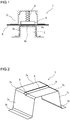
- FIG. 1 is an illustration schematically showing a configuration example of a press forming apparatus that performs general bending forming.
- a press forming apparatus 1 is an apparatus for producing a press formed product having a channel cross-section or a hat-shaped cross-section.
- FIG. 1 illustrates the case of producing a press formed product having a hat-shaped cross-section (see a dashed line in FIG. 1 ).
- the press forming apparatus 1 includes a punch 2 as a lower die, and includes a die 3 and a pad 5, which are paired with the punch 2, as an upper die.
- the pad 5 is supported by the die 3 or by an upper die holder or slide integrally operated with the die 3 via a pressure member 4.
- the pad 5 can be received in the die 3, and constitutes a part of the die 3 with being received in the die 3.
- the bending forming of forming a metal sheet 6 into a press formed product by such press forming apparatus 1 is performed as follows. Before the forming, the metal sheet 6 is sandwiched between the punch 2 and the pad 5. That is, before staring the pushing-in of the metal sheet 6 into the die 3 by the punch 2, a portion of the metal sheet 6, which portion is formed into a top panel part of the press formed product, is restrained by the punch 2 and the pad 5. In this state, the die 3 is descended to a bottom dead point. In this manner, the top panel part of the press formed product is formed along a top surface (a front end surface) 2a of the punch 2. Vertical wall parts are formed along side surfaces 2b of the punch 2. Ridge line parts are formed between the top panel part and the vertical wall parts. The ridge line parts connecting the top panel part to the vertical wall parts are formed along punch shoulder parts 2c of the punch 2.
- such bending forming is referred to as the pad bending forming.
- a high-strength steel sheet having a tensile strength of 440 MPa or more is used as the metal sheet 6, which is the starting material of the structural member.
- a 590 MPa-class high-strength steel sheet is also used, and in some cases, a 980 MPa-class high-strength steel sheet, or even a 1180 MPa-class high-strength steel sheet is used.
- the shapes of the structural members may become relatively complex. This is because of the design constraints, such as prevention of the interference between the structural members and the other members, bonding between the structural members and the other members, securing of a desired space, etc.
- FIGS. 2 to 8 are perspective views showing examples of press formed products having relatively complex shapes.
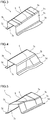
- FIG. 2 shows a first exemplary press formed product 7 formed from a high-strength steel sheet having a tensile strength of 590 MPa or more (an alloyed hot-dip galvanized steel sheet made of DP (Dual Phase) steel having a sheet thickness of 1.2 mm).
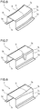
- FIGS. 3 to 8 show second to seventh exemplary press formed products 7 formed from a high-strength steel sheet having a tensile strength of 440 MPa or more (an alloyed hot-dip galvanized steel sheet, a non-plated steel sheet, etc. having a sheet thickness of about 1.2 mm), respectively.
- each of the cross-section shapes of the first to seventh exemplary press formed products 7 is a hat shape. That is, each of the press formed products 7 includes a top panel part 7a, vertical wall parts 7c extending from the left and right ends of the top panel part 7a, ridge line parts 7b between the top panel part 7a and the vertical wall parts 7c, and flange parts 7d extending from the lower ends of the respective vertical wall parts 7c. Further, the press formed product 7 includes shape-changing parts 9 in parts of the ridge line parts 7b.
- the shape-changing parts 9 are provided in both of the ridge line parts 7b on both ends of the top panel part 7a.
- the height of the ridge line parts 7b is changed at local portions located in almost middle of the lengthwise direction of the press formed product 7.
- a step height part 8 is formed in the top panel part 7a in a region connecting the shape-changing parts 9 to each other.
- the shape-changing parts 9 are provided in both of the ridge line parts 7b on both ends of the top panel part 7a.
- the height of the ridge line parts 7b is changed in a wide area almost in the middle of the lengthwise direction of the press formed product 7.
- the height of the top panel part 7a gently changes corresponding to the positions of the shape-changing parts 9.
- the shape-changing part 9 is provided in one of the ridge line parts 7b on both ends of the top panel part 7a.
- This shape-changing part 9 change the arc length in a cross section of the ridge line part 7b at a local portion almost in the middle of the lengthwise direction of the press formed product 7.
- the angle between the top panel part 7a and the vertical wall part 7c changes corresponding to the position of the shape-changing part 9.
- the shape-changing parts 9 are provided in both of the ridge line parts 7b on both ends of the top panel part 7a.
- the ridge line parts 7b are twisted in a wide area almost in the middle of the lengthwise direction of the press formed product 7.
- the top panel part 7a and the vertical wall parts 7c are twisted corresponding to the positions of the shape-changing parts 9.
- the shape-changing parts 9 are provided in both of the ridge line parts 7b on both ends of the top panel part 7a.
- the ridge line parts 7b are warped in the width direction of the press formed product 7 in a wide area almost in the middle of the lengthwise direction of the press formed product 7.
- the top panel part 7a and the vertical wall parts 7c are warped in the width direction of the press formed product 7 corresponding to the positions of the shape-changing parts 9.
- the shape-changing part 9 is provided in one of the ridge line parts 7b on both ends of the top panel part 7a.
- this ridge line part 7b is hollowed in the width direction of the press formed product 7 at a local portion almost in the middle of the lengthwise direction of the press formed product 7.
- the top panel part 7a and the vertical wall parts 7c are hollowed in the width direction of the press formed product 7 corresponding to the position of the shape-changing part 9.
- the shape-changing part 9 is provided in one of the ridge line parts 7b on both ends of the top panel part 7a.
- this shape-changing part 9 the radius of curvature of a cross section of the ridge line part is changed in an area from almost the middle to one end of the lengthwise direction of the press formed product 7.
- the width of the top panel part 7a and the height of the vertical wall part 7c are changed corresponding to the position of the shape-changing part 9.
- Such a wrinkle similarly occurs even in the second to seventh exemplary press formed products 7 shown in FIGS. 3 to 8 .
- Aiming to suppress the occurrence of such a wrinkle reduces the degree of freedom in designing the structural members. This is because the various dimensions of the shape-changing parts 9 in the ridge line parts 7b are restricted in accordance with the press formability of a high-strength steel sheet, which is a starting material.
- Patent Literature 1 Japanese Patent Application Publication No. 2010-115674
- Patent Literature 2 Japanese Patent Application Publication No. 2012-024837
- Patent Literature 1 discloses the technique for applying concavo-convex beads to vertical wall parts and flange parts. With the application of the beads, the line length difference is reduced that is generated in an end part of a starting material before and after bending forming. In this manner, the generation of wrinkles is suppressed.
- Patent Literature 2 is directed to the production of a press formed product having a hat-shaped cross-section shape and bent in the width direction, and discloses the technique for suppressing wrinkles generated in outer vertical wall parts, etc. of a bending portion of the press formed product.
- an excess thickness portion is provided only on the outer side of the bending portion.
- the excess thickness portion is bent in the direction opposite to the press direction by upper and lower dies, and is also sandwiched between the dies. In this manner, tensile force is applied to the outside of the bending portion, and the generation of wrinkles is suppressed.
- Patent Literature 2 cannot be necessarily applied to the production of all of the above-described first to seventh exemplary press formed products 7. Additionally, according to this technique, because the excess thickness portion exists, the yield reduction cannot be avoided.
- An object of the present invention is to provide a producing method and a producing apparatus of a press formed product that can reduce the generation of wrinkles in the region of the shape-changing part and the region in the vicinity thereof, even in the case where, for example, a high-strength steel sheet is used as the starting material, when forming the press formed product having a channel cross-section or a hat-shaped cross-section and including a shape-changing part in a part of the ridge line parts.
- the punch includes a front end surface, side surfaces, and punch shoulder parts provided between the front end surface and the side surfaces.
- the punch shoulder parts are provided with a shape-changing part in a part of a longitudinal direction of the punch.
- the pad includes a bottom surface opposing the front end surface of the punch, inner side surfaces opposing a part of the side surfaces of the punch, and corner parts provided between the bottom surface and the inner side surfaces and opposing the punch shoulder parts.
- the die includes inner side surfaces opposing, of regions of the side surfaces of the punch, regions except for regions opposing the inner side surfaces of the pad.
- the predetermined height is 2 mm or more from the border between the vertical wall part and the ridge line part, and is equal to or less than a half of the total height of the vertical wall part.
- the producing apparatus according to the above-described (2) can employ the following configuration.
- the bottom surface of the pad corresponds to the entire region of the top panel part.
- Each of the corner parts of the pad corresponds to the entire region of each of the ridge line parts.
- Each of the inner side surfaces of the pad corresponds to a region up to the predetermined height from the border between the vertical wall part and the ridge line part of a region of each of the vertical wall parts.
- the die includes inner side surfaces corresponding to regions beyond the predetermined height of regions of the respective vertical wall parts.
- the die is divided to correspond to each of the vertical wall parts.
- the producing apparatus includes a die moving mechanism that moves each of the dies toward a respective one of the side surfaces of the punch after completion of pushing-in of the starting material into the pad by the punch.
- the present invention it is possible to reduce the occurrence of a wrinkle in the region of the shape-changing part and the region in the vicinity thereof, even in the case where, for example, a high-strength steel sheet is used as the starting material, when forming the press formed product having a channel cross-section or a hat-shaped cross-section including the shape-changing part in a part of the ridge line part.
- the region formed into the ridge line part and the region formed into the vertical wall part are processed sequentially with the pushing-in of the punch into the die, after the region of the top panel part is restrained by the punch and the pad.
- the generation of wrinkles can be reduced by suppressing the excessive material excess in the region of the shape-changing part and the region in the vicinity thereof.
- the region restrained by the punch and the pad from the early phase of the press working (hereinafter referred to as the "restrained region") should be increased.
- the restrained region is not only the region of the top panel part, but also the region of the shape-changing part and a part of the region of the vertical wall part adjacent to the shape-changing part, where a wrinkle is likely to be generated. In this manner, at the time of press working, there is no room for a material excess to be generated in the region of the shape-changing part and the region in the vicinity thereof, and the generation of wrinkles is reduced.
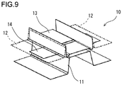
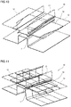
- FIGS. 9 to 11 are perspective views showing an example of the structure of a producing apparatus used in producing a press formed product in a first embodiment of the present invention.
- Each of the producing apparatuses 10 shown in FIGS. 9 to 11 is a press forming apparatus.
- the press forming apparatus 10 shown in FIG. 9 is an apparatus that produces the first exemplary press formed product 7 having the hat-shaped cross-section shown in the above-described FIG. 2 .
- the press forming apparatus 10 shown in FIG. 10 is an apparatus that produces the second exemplary press formed product 7 having the hat-shaped cross-section shown in the above-described FIG. 3 .
- the press forming apparatus 10 shown in FIG. 11 is an apparatus that produces the sixth exemplary press formed product 7 having the hat-shaped cross-section shown in the above-described FIG. 7 .
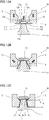
- FIGS. 12A to 12C are diagrams showing the statuses of the press working step by the producing apparatus of the first embodiment.
- FIG. 12A shows the state before starting the forming.
- FIG. 12B shows the state of the early phase of the forming.
- FIG. 12C shows the state at the completion of the forming.
- These figures show the cross sections of the region(s) of the shape-changing part(s).
- the press forming apparatus 10 includes a punch 11 as a lower die, and includes a die 12 and a pad 13 as an upper die. That is, the punch 11 makes a pair with the die 12 and the pad 13. Note that FIGS. 9 to 11 show the die 12 by a dashed line, so as to facilitate the understanding of the structure.
- the punch 11 includes a top surface 11a (a front end surface), a pair of side surfaces 11b, and punch shoulder parts 11c provided between the top surface 11a and the side surfaces 11b.
- the punch shoulder parts 11c are regions connecting the top surface 11a to the side surfaces 11b.
- the shape of the top surface 11a is the shape corresponding to the region of the top panel part 7a of the press formed product 7.
- the shapes of the side surfaces 11b are the shapes corresponding to the region of the vertical wall parts 7c of the press formed product 7.
- the shape of the punch shoulder part 11c is the shape corresponding to the region of the ridge line part 7b (including the shape-changing part 9) of the press formed product 7.
- the punch shoulder part 11c is provided with a shape-changing part in a part of the longitudinal direction of the punch 11.
- the shape of the shape-changing part of the punch shoulder part 11c is the shape corresponding to the region of the shape-changing part 9 that exists in a part of the ridge line part 7b of the press formed product 7.
- the punch shoulder part 11c includes a portion where the cross-section shape changes in the longitudinal direction of the punch 11, or where the extending direction of the punch shoulder part 11c is bent.
- the pad 13 is arranged opposed to the top surface 11a of the punch 11.
- the pad 13 includes a bottom surface 13a, a pair of inner side surfaces 13b, and corner parts 13c.
- the corner parts 13c are portions that connect the bottom surface 13a to the inner side surfaces 13b.
- the shape of the bottom surface 13a is the shape corresponding to the region of the top panel part 7a of the press formed product 7. That is, the bottom surface 13a opposes the top surface 11a of the punch 11, and its shape is the shape conforming to the top surface 11a of the punch 11.
- the shape of the corner part 13c is the shape corresponding to the region of the ridge line part 7b (including the shape-changing part 9) of the press formed product 7.
- the corner part 13c opposes the punch shoulder part 11c, and its shape is the shape conforming to the punch shoulder part 11c.
- the shape conforming means the shape where the convexity and concavity of the opposing portions with the material metal sheet sandwiched therebetween is inverted.
- the inner side surface 13b opposes a part of the side surface 11b of the punch 11.
- the shape of the inner side surface 13b is the shape corresponding to the region having a predetermined height h from the border between the vertical wall part 7c and the ridge line part 7b of the region of the vertical wall part 7c of the press formed product 7 (see FIG. 12C ).
- the pad 13 is supported by an upper die holder integrally operated with a slide via a pressure member.
- the pressure member is a hydraulic cylinder, a gas cylinder, a spring, a rubber, etc., and applies a downward force (a force directed to the punch 11) to the pad 13.
- the pad 13 may be supported by a slide that operates integrally with the upper die holder.
- the die 12 is divided into two, and each of the dies 12 is arranged on each of the outer sides of the pad 13.
- Each of the dies 12 includes an inner side surface 12a.
- the shape of the inner side surface 12a is the shape corresponding to the region beyond the predetermined height h of the region of the vertical wall part 7c of the press formed product 7. That is, the inner side surface 12a opposes a region of the regions of the side surface 11b of the punch 11 except for the regions opposing the inner side surface 13b of the pad 13.
- Each of the dies 12 is connected to the upper die holder or slide via a die moving mechanism such as a cam.
- the die moving mechanism moves each of the dies 12 obliquely downward to a respective one of the side surfaces 11b of the punch 11 (see the outlined arrows in FIG. 12B ).
- the producing method of the press formed product 7 using such press forming apparatus 10 according to the first embodiment includes a preparation step and a press working step as follows.
- a metal sheet 14 is prepared as a starting material.
- a high-strength steel sheet having a tensile strength of 440 MPa or more can be used as the metal sheet 14.
- the metal sheet 14 may be a 590 MPa-class high-strength steel sheet, a 980 MPa-class high-strength steel sheet, or even a 1180 MPa-class high-strength steel sheet.
- a stainless steel sheet, an aluminum sheet, a copper sheet, etc. may also be used as the metal sheet 14.
- press working step press working by bending forming is performed on the metal sheet 14 by using the press forming apparatus 10, so as to produce the press formed product 7.
- the press working step press working by bending forming is performed on the metal sheet 14 by using the press forming apparatus 10, so as to produce the press formed product 7.
- each of the dies 12 is moved, by the die moving mechanism, obliquely downward toward a respective one of the side surfaces 11b of the punch 11, such that the dies 12 are become close to each other (see the outlined arrows in FIG. 12B ).
- the working by the punch 11 and the dies 12 is begun, and the region beyond the predetermined height h is formed in the region of each of the vertical wall parts 7c (see FIG. 12C ). That is, the remaining regions are formed by the punch 11 and the dies 12.
- the flange parts 7d which are connected to the vertical wall parts 7c, are also formed by the punch 11 and the dies 12. In this way, the press formed product 7 is obtained.
- the region of the shape-changing part 9 and a part of the region of the vertical wall part 7c adjacent to the shape-changing part 9, where a wrinkle is likely to be generated are restrained by the punch 11 and the pad 13 from the early phase of the working. Therefore, at the time of press working, there is no room for a material excess to be generated in the region of the shape-changing part 9 and the region in the vicinity thereof. As a result, even when a high-strength steel sheet is used as the starting material, it is possible to suppress the generation of wrinkles in the region of the shape-changing part 9 and the region in the vicinity thereof. Accordingly, in the case where the press formed product having a relatively complex shape is produced, it is possible to expedite the increasing of the strength, and it is also possible to increase the degree of freedom in designing.
- the region of each of the vertical wall parts 7c adjacent to the shape-changing part 9 is formed such that, first, the region having the predetermined height h is formed by the pad 13 and the punch 11, and thereafter, the remaining regions are formed by the dies 12 and the punch 11. It is preferable that the predetermined height h is 2 mm or more from the border between the vertical wall part 7c and the ridge line part 7b, and is equal to or less than a half of the total height H (H/2) of the vertical wall part 7c. The reason is as follows.
- the predetermined height h is less than 2 mm from the border between the vertical wall part 7c and the ridge line part 7b, at the time of the subsequent working by the dies 12 and the punch 11, the working regions of the vertical wall parts 7c become broad, and a wrinkle is likely to be generated.
- the predetermined height h is more than a half of the total height H of the vertical wall part 7c, at the time of the aforementioned working by the pad 13 and the punch 11, the working regions of the vertical wall parts 7c become broad, and also in this case, a wrinkle is likely to be generated.
- the lower limit for the predetermined height h is preferably 3 mm, and more preferably 5 mm.
- the upper limit for the predetermined height h is preferably 40 mm, and more preferably, 20 mm.
- the press formed product 7 to be produced in the first embodiment is not limited to the first, second and sixth exemplary press formed product 7 having the hat-shaped cross-section shown in FIG. 2 , 3 and 7 . That is, the press formed product 7 may be the third to fifth and seventh exemplary press formed products 7 shown in the above-described FIGS. 4 to 6 and FIG.8 , as long as a part of the ridge line part 7b includes a shape-changing part 9.
- the shape-changing part 9 of the ridge line part 7b of the press formed product 7 is at least one of (a) to (f) as follows:
- the pair of ridge line parts of the press formed product does not have to be parallel.
- a pair of ridge line parts may be crossed at their ends.
- the cross-section shape of the press formed product may be a channel shape without the flange parts.
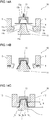
- FIGS. 13A to 13C are diagrams showing the statuses of the press working step by a producing apparatus according to a second embodiment.
- FIG. 13A shows the state before starting the forming.
- FIG. 13B shows the state of the early phase of the forming.
- FIG. 13C shows the state at the completion of the forming.
- These figures show the cross sections of the region(s) of the shape-changing part(s), as in FIGS. 12A to 12C .
- a second embodiment is based on the first embodiment, and modifies a part of the first embodiment.
- the height of the inner side surface 13b of the pad 13 is larger compared to the above-described first embodiment.
- Each of the dies 12 is arranged adjacent to the either side of the pad 13, and is fixed directly to the upper die holder. That is, no special die moving mechanism is provided. Further, in the case of the second embodiment, the die 12 may be integral without being divided into two.
- the press working step of the second embodiment first, the working by the punch 11 and the pad 13 is completed with the descending of the upper die holder (see FIG. 13B ). Then, the descending of the upper die holder is subsequently continued. Consequently, each of the dies 12 descends directly, and reaches to the bottom dead point (see the outlined arrows in FIG. 13B ). In this manner, in each of the regions of the vertical wall parts 7c, the region beyond the predetermined height h is formed by the punch 11 and the die 12 (see FIG. 13C ). In this way, the press formed product 7 is obtained.
- the press working step of the second embodiment it is also possible to reduce the generation of wrinkles in the region of the shape-changing part 9 and the region in the vicinity thereof, as in the above-described first embodiment. Additionally, in the second embodiment, it is unnecessary to provide a special die moving mechanism. Therefore, the apparatus configuration is simple.
- FIGS. 14A to 14C are diagrams showing the statuses of the press working step by a producing apparatus according to a third embodiment.
- FIG. 14A shows the state before starting the forming.
- FIG. 14B shows the state of the early phase of the forming.
- FIG. 14C shows the state at the completion of the forming.
- These figures show the cross sections of the region(s) of the shape-changing part(s), as in FIGS. 12A to 12C , and FIGS. 13A to 13C .
- a third embodiment is based on the second embodiment, and modifies a part of the second embodiment.
- the substantial working regions of the vertical wall parts 7c by the dies 12 and the punch 11 are front end parts (lower bottom parts) of the vertical wall parts 7c, and are significantly narrow. Therefore, the addition of a restriking step for fine adjusting the shape may be required.
- the third embodiment improves such a disadvantage (an increase in the steps) of the second embodiment.
- Each of the dies 12 in the third embodiment is arranged on either outer side of the punch 11.
- Each of the dies 12 is connected to a lower die holder or bolster via a die moving mechanism such as a cam.
- Each of the dies 12 may be connected to the upper die holder or slide via the die moving mechanism such as a cam, as in the above-described first embodiment.
- the die moving mechanism in the third embodiment moves each of the dies 12 horizontally toward a respective one of the side surfaces 11b of the punch 11 (see outlined arrows in FIG. 14B ).
- the press working step of the third embodiment first, the working by the punch 11 and the pad 13 is completed with the descending of the upper die holder (see FIG. 14B ). Then, the descending of the upper die holder is subsequently continued to the bottom dead point. Consequently, each of the dies 12 is moved, by the die moving mechanism, horizontally toward a respective one of the side surfaces 11b of the punch 11, such that the dies 12 become closer to each other (see the outlines arrows in FIG. 14B ). In this manner, in the region of each of the vertical wall parts 7c, the region beyond the predetermined height h is formed (see FIG. 14C ). In this way, the press formed product 7 is obtained.
- the press working step of the third embodiment it is also possible to reduce the generation of wrinkles in the region of the shape-changing part 9 and the region in the vicinity thereof, as in the above-described first and second embodiments. Additionally, in the third embodiment, it is possible to suppress the addition of the restriking step, which may occur in the second embodiment, because the substantial working regions of the vertical wall parts 7c by the dies 12 and the punch 11 are broad.
- the present invention is not limited to the above-described embodiments, and various modifications can be made without departing from the spirit of the present invention.
- the press forming apparatus of the above-described embodiments has the structure that includes the punch as the lower die, and includes the die and the pad as the upper die
- the press forming apparatus of the above-described embodiments may have the structure in which the arrangement of the upper and lower dies is inverted.
- the restrained region of the top panel part by the punch and the pad may be at least a region adjacent to the shape-changing part of the region of the top panel part.
- the restrained region of the ridge line part by the punch and the pad may be at least a region of the shape-changing part in the region of each of the ridge line parts.
- the restrained region of the vertical wall part by the punch and the pad may be at least a region adjacent to the shape-changing part and up to the predetermined height h in each of the vertical wall parts.
- those regions that are not adjacent to the shape-changing part(s) may be formed by the pad, or may be formed by a separate pad.
- those regions except for the shape-changing part(s) may be formed by the pad, or may be formed by the dies.
- those regions that are not adjacent to the shape-changing part(s) may be formed by the pad, or may be formed by the dies.
- the degree of generation of wrinkles was studied in the case of producing the second exemplary press formed product 7 shown in the above-described FIG. 3 .
- an FEM analysis was conducted assuming the press working according to the first embodiment shown in the above-described FIGS. 12A to 12C .
- an FEM analysis was conducted assuming the pad bending forming shown in the above-described FIG. 1 .
- a DP steel having a 590 MPa-class tensile strength and a sheet thickness of 1.2 mm was used as the starting material.
- the sheet thickness increase rate was calculated for the shape-changing part, where it was feared that a wrinkle might be generated.
- the sheet thickness increase rate A is expressed by the following Formula (1).
- A t 1 ⁇ t 0 / t 0 ⁇ 100 %
- t0 represents the sheet thickness before the press working
- t1 represents the sheet thickness after the press working
- FIG. 15 is a graph showing the study result of the example.
- the sheet thickness increase rate in the shape-changing part was more than 15%, and the generation of wrinkles was expected.
- the sheet thickness increase rate in the shape-changing part was suppressed to about 4%, which was the level at which a wrinkle was not generated.
Landscapes
- Engineering & Computer Science (AREA)
- Mechanical Engineering (AREA)
- Shaping Metal By Deep-Drawing, Or The Like (AREA)
- Bending Of Plates, Rods, And Pipes (AREA)
Abstract
Description
- The present invention relates to a method and an apparatus for producing a press formed product used in automobiles, various vehicles other than automobiles, home appliances, vessels, architectural materials, etc.
- For example, the car body of an automobile includes various structural members (examples: floor cross members, side sills, side members, etc.). Press formed products, which use metal sheets such as steel sheets as their starting materials, are heavily used in the structural members. Due to the advantages over material rupture, shape fixability, and producing cost at the time of press forming, in many cases, a press formed product is obtained by performing press working on a metal sheet through bending forming. The press formed product has, for example, a channel cross-section shape or a hat-shaped cross-section shape. The press formed product having a channel cross-section includes a top panel part and a pair of vertical wall parts extending from the top panel part. The press formed product having a hat-shaped cross-section further includes a pair of flange parts extending from the respective vertical wall parts.
-
FIG. 1 is an illustration schematically showing a configuration example of a press forming apparatus that performs general bending forming. As shown inFIG. 1 , apress forming apparatus 1 is an apparatus for producing a press formed product having a channel cross-section or a hat-shaped cross-section.FIG. 1 illustrates the case of producing a press formed product having a hat-shaped cross-section (see a dashed line inFIG. 1 ). Thepress forming apparatus 1 includes apunch 2 as a lower die, and includes adie 3 and apad 5, which are paired with thepunch 2, as an upper die. Thepad 5 is supported by the die 3 or by an upper die holder or slide integrally operated with the die 3 via apressure member 4. Thepad 5 can be received in the die 3, and constitutes a part of the die 3 with being received in the die 3. - The bending forming of forming a
metal sheet 6 into a press formed product by suchpress forming apparatus 1 is performed as follows. Before the forming, themetal sheet 6 is sandwiched between thepunch 2 and thepad 5. That is, before staring the pushing-in of themetal sheet 6 into thedie 3 by thepunch 2, a portion of themetal sheet 6, which portion is formed into a top panel part of the press formed product, is restrained by thepunch 2 and thepad 5. In this state, the die 3 is descended to a bottom dead point. In this manner, the top panel part of the press formed product is formed along a top surface (a front end surface) 2a of thepunch 2. Vertical wall parts are formed alongside surfaces 2b of thepunch 2. Ridge line parts are formed between the top panel part and the vertical wall parts. The ridge line parts connecting the top panel part to the vertical wall parts are formed alongpunch shoulder parts 2c of thepunch 2. Hereinafter, such bending forming is referred to as the pad bending forming. - In these years, it is required for automobiles to save the car body weight, so as to improve the fuel economy, which contributes to prevention of global warming. Further, the improvement of the safety at the time of collision accident is required. Because of these requirements, a high-strength steel sheet having a tensile strength of 440 MPa or more is used as the
metal sheet 6, which is the starting material of the structural member. For example, a 590 MPa-class high-strength steel sheet is also used, and in some cases, a 980 MPa-class high-strength steel sheet, or even a 1180 MPa-class high-strength steel sheet is used. - Additionally, the shapes of the structural members may become relatively complex. This is because of the design constraints, such as prevention of the interference between the structural members and the other members, bonding between the structural members and the other members, securing of a desired space, etc.
-
FIGS. 2 to 8 are perspective views showing examples of press formed products having relatively complex shapes. Among these figures,FIG. 2 shows a first exemplary press formedproduct 7 formed from a high-strength steel sheet having a tensile strength of 590 MPa or more (an alloyed hot-dip galvanized steel sheet made of DP (Dual Phase) steel having a sheet thickness of 1.2 mm).FIGS. 3 to 8 show second to seventh exemplary press formedproducts 7 formed from a high-strength steel sheet having a tensile strength of 440 MPa or more (an alloyed hot-dip galvanized steel sheet, a non-plated steel sheet, etc. having a sheet thickness of about 1.2 mm), respectively. - Each of the cross-section shapes of the first to seventh exemplary press formed
products 7 is a hat shape. That is, each of the press formedproducts 7 includes atop panel part 7a,vertical wall parts 7c extending from the left and right ends of thetop panel part 7a,ridge line parts 7b between thetop panel part 7a and thevertical wall parts 7c, andflange parts 7d extending from the lower ends of the respectivevertical wall parts 7c. Further, the press formedproduct 7 includes shape-changingparts 9 in parts of theridge line parts 7b. - In the first exemplary press formed
product 7 shown inFIG. 2 , the shape-changingparts 9 are provided in both of theridge line parts 7b on both ends of thetop panel part 7a. In these shape-changingparts 9, the height of theridge line parts 7b is changed at local portions located in almost middle of the lengthwise direction of the press formedproduct 7. In this case, astep height part 8 is formed in thetop panel part 7a in a region connecting the shape-changingparts 9 to each other. - In the second exemplary press formed
product 7 shown inFIG. 3 , the shape-changingparts 9 are provided in both of theridge line parts 7b on both ends of thetop panel part 7a. In these shape-changingparts 9, the height of theridge line parts 7b is changed in a wide area almost in the middle of the lengthwise direction of the press formedproduct 7. In this case, the height of thetop panel part 7a gently changes corresponding to the positions of the shape-changingparts 9. - In the third exemplary press formed
product 7 shown inFIG. 4 , the shape-changingpart 9 is provided in one of theridge line parts 7b on both ends of thetop panel part 7a. This shape-changingpart 9 change the arc length in a cross section of theridge line part 7b at a local portion almost in the middle of the lengthwise direction of the press formedproduct 7. In this case, the angle between thetop panel part 7a and thevertical wall part 7c changes corresponding to the position of the shape-changingpart 9. - In the fourth exemplary press formed
product 7 shown inFIG. 5 , the shape-changingparts 9 are provided in both of theridge line parts 7b on both ends of thetop panel part 7a. In these shape-changingparts 9, theridge line parts 7b are twisted in a wide area almost in the middle of the lengthwise direction of the press formedproduct 7. In this case, thetop panel part 7a and thevertical wall parts 7c are twisted corresponding to the positions of the shape-changingparts 9. - In the fifth exemplary press formed
product 7 shown inFIG. 6 , the shape-changingparts 9 are provided in both of theridge line parts 7b on both ends of thetop panel part 7a. In these shape-changingparts 9, theridge line parts 7b are warped in the width direction of the press formedproduct 7 in a wide area almost in the middle of the lengthwise direction of the press formedproduct 7. In this case, thetop panel part 7a and thevertical wall parts 7c are warped in the width direction of the press formedproduct 7 corresponding to the positions of the shape-changingparts 9. - In the sixth exemplary press formed
product 7 shown inFIG. 7 , the shape-changingpart 9 is provided in one of theridge line parts 7b on both ends of thetop panel part 7a. In the shape-changingpart 9, thisridge line part 7b is hollowed in the width direction of the press formedproduct 7 at a local portion almost in the middle of the lengthwise direction of the press formedproduct 7. In this case, thetop panel part 7a and thevertical wall parts 7c are hollowed in the width direction of the press formedproduct 7 corresponding to the position of the shape-changingpart 9. - In the seventh exemplary press formed
product 7 shown inFIG. 8 , the shape-changingpart 9 is provided in one of theridge line parts 7b on both ends of thetop panel part 7a. In this shape-changingpart 9, the radius of curvature of a cross section of the ridge line part is changed in an area from almost the middle to one end of the lengthwise direction of the press formedproduct 7. In this case, the width of thetop panel part 7a and the height of thevertical wall part 7c are changed corresponding to the position of the shape-changingpart 9. - When cold producing the first exemplary press formed
product 7 shown inFIG. 2 from a high-strength steel sheet by the pad bending forming shown inFIG. 1 , the following problems occur. In the press formedproduct 7, a wrinkle is generated in the regions of the shape-changingparts 9 of theridge line part 7b and in the regions in the vicinity thereof (thevertical wall parts 7c, etc.). - Such a wrinkle similarly occurs even in the second to seventh exemplary press formed
products 7 shown inFIGS. 3 to 8 . - Aiming to suppress the occurrence of such a wrinkle reduces the degree of freedom in designing the structural members. This is because the various dimensions of the shape-changing
parts 9 in theridge line parts 7b are restricted in accordance with the press formability of a high-strength steel sheet, which is a starting material. - The prior arts for preventing the occurrence of a wrinkle in press formed products are disclosed in, for example, Japanese Patent Application Publication No.
2010-115674 2012-024837 -
Patent Literature 1 discloses the technique for applying concavo-convex beads to vertical wall parts and flange parts. With the application of the beads, the line length difference is reduced that is generated in an end part of a starting material before and after bending forming. In this manner, the generation of wrinkles is suppressed. -
Patent Literature 2 is directed to the production of a press formed product having a hat-shaped cross-section shape and bent in the width direction, and discloses the technique for suppressing wrinkles generated in outer vertical wall parts, etc. of a bending portion of the press formed product. In this technique, an excess thickness portion is provided only on the outer side of the bending portion. At the time of press forming, the excess thickness portion is bent in the direction opposite to the press direction by upper and lower dies, and is also sandwiched between the dies. In this manner, tensile force is applied to the outside of the bending portion, and the generation of wrinkles is suppressed. -
- Patent Literature 1: Japanese Patent Application Publication No.
2010-115674 - Patent Literature 2: Japanese Patent Application Publication No.
2012-024837 - According to the technique disclosed in
Patent Literature 1, concavo-convex shapes of beads appear on the press formed product. Therefore, the application of this technique is limited to the production of a special press formed product. - The technique disclosed in
Patent Literature 2 cannot be necessarily applied to the production of all of the above-described first to seventh exemplary press formedproducts 7. Additionally, according to this technique, because the excess thickness portion exists, the yield reduction cannot be avoided. - As described above, according to the prior art, when forming the press formed product having a shape-changing part in a part of the ridge line parts from a high-strength steel sheet having a tensile strength of, for example, 440 MPa or more, it is impossible to reduce the generation of wrinkles in the region of the shape-changing part and the region in the vicinity thereof.
- An object of the present invention is to provide a producing method and a producing apparatus of a press formed product that can reduce the generation of wrinkles in the region of the shape-changing part and the region in the vicinity thereof, even in the case where, for example, a high-strength steel sheet is used as the starting material, when forming the press formed product having a channel cross-section or a hat-shaped cross-section and including a shape-changing part in a part of the ridge line parts.
-
- (1) A producing method according to an embodiment of the present invention is a method for producing a press formed product from a starting material.
The press formed product includes a top panel part, vertical wall parts respectively extending from both ends of the top panel part, and ridge line parts between the vertical wall parts and the top panel part, and includes a shape-changing part in a part of the ridge line parts.
The producing method includes:- a preparation step of preparing a metal sheet as the starting material; and
- a press working step of performing press working on the starting material by using a punch, and a pad and a die that are paired with the punch.
The press working step includes:- a first step of forming, by the punch and the pad, at least a region adjacent to the shape-changing part of a region of the top panel part, at least a region of the shape-changing part of a region of each of the ridge line parts, and at least a region adjacent to the shape-changing part of a region of each of the vertical wall parts and up to a predetermined height from a border between the vertical wall part and the ridge line part; and
- a second step of forming, subsequent to the first step, by the punch and the die, the remaining regions, with the starting material sandwiched between the punch and the pad.
In the producing method according to the above-described (1), it is preferable that the predetermined height is 2 mm or more from the border between the vertical wall part and the ridge line part, and is equal to or less than a half of the total height of the vertical wall part.
The producing method of the above-described (1) can employ the following configuration.
In the first step, the entire region of the top panel part, the entire region of each of the ridge line parts, and a region up to the predetermined height from the border between the vertical wall part and the ridge line part of a region of each of the vertical wall parts are formed by the punch and the pad.
In the second step, a region beyond the predetermined height of the region of each of the vertical wall parts is formed by the punch and the die.
The producing method of the above-described (1) can employ the following configuration.
The shape-changing part of the ridge line part is at least one of (a) to (f) as follows:- (a) the height of the ridge line part is changed;
- (b) the arc length in the cross section of the ridge line part is changed;
- (c) the ridge line part is twisted;
- (d) the ridge line part is bent in the width direction;
- (e) the ridge line part protrudes or is hollowed in the width direction; and
- (f) the radius of curvature in the cross section of the ridge line part is changed.
- (2) A producing apparatus according to an embodiment of the present invention is an apparatus for producing a press formed product from a starting material.
The press formed product includes a top panel part, vertical wall parts respectively extending from both ends of the top panel part, and ridge line parts between the vertical wall parts and the top panel part, and includes a shape-changing part in a part of the ridge line parts.
The producing apparatus includes a punch, and a pad and a die that are paired with the punch.
The punch includes a front end surface corresponding to a region of the top panel part, side surfaces corresponding to regions of the respective vertical wall parts, and punch shoulder parts corresponding to regions of the respective ridge line parts.
The pad includes a bottom surface corresponding to at least a region adjacent to the shape-changing part of a region of the top panel part, a corner part corresponding to at least a region of the shape-changing part of a region of each of the ridge line parts, and an inner side surface corresponding to at least a region adjacent to the shape-changing part of a region of each of the vertical wall parts and up to a predetermined height from a border between the vertical wall part and the ridge line part. - (3) A producing apparatus of a press formed product according to an embodiment of the present invention includes a punch, a pad and a die.
- The punch includes a front end surface, side surfaces, and punch shoulder parts provided between the front end surface and the side surfaces. The punch shoulder parts are provided with a shape-changing part in a part of a longitudinal direction of the punch.
- The pad includes a bottom surface opposing the front end surface of the punch, inner side surfaces opposing a part of the side surfaces of the punch, and corner parts provided between the bottom surface and the inner side surfaces and opposing the punch shoulder parts.
- The die includes inner side surfaces opposing, of regions of the side surfaces of the punch, regions except for regions opposing the inner side surfaces of the pad.
- In the producing apparatus according to the above-described (2), it is preferable that the predetermined height is 2 mm or more from the border between the vertical wall part and the ridge line part, and is equal to or less than a half of the total height of the vertical wall part.
- The producing apparatus according to the above-described (2) can employ the following configuration.
- The bottom surface of the pad corresponds to the entire region of the top panel part. Each of the corner parts of the pad corresponds to the entire region of each of the ridge line parts. Each of the inner side surfaces of the pad corresponds to a region up to the predetermined height from the border between the vertical wall part and the ridge line part of a region of each of the vertical wall parts.
- The die includes inner side surfaces corresponding to regions beyond the predetermined height of regions of the respective vertical wall parts.
- In the case of this producing apparatus, it is preferable that the following configuration is employed.
- The die is divided to correspond to each of the vertical wall parts.
- The producing apparatus includes a die moving mechanism that moves each of the dies toward a respective one of the side surfaces of the punch after completion of pushing-in of the starting material into the pad by the punch.
- According to the present invention, it is possible to reduce the occurrence of a wrinkle in the region of the shape-changing part and the region in the vicinity thereof, even in the case where, for example, a high-strength steel sheet is used as the starting material, when forming the press formed product having a channel cross-section or a hat-shaped cross-section including the shape-changing part in a part of the ridge line part.
-
- [
FIG. 1] FIG. 1 is a cross-sectional view schematically showing an exemplary structure of a press forming apparatus performing general bending forming. - [
FIG. 2] FIG. 2 is a perspective view showing an example of a press formed product having a relatively complex shape. - [
FIG. 3] FIG. 3 is a perspective view showing an example of a press formed product having a relatively complex shape. - [
FIG. 4] FIG. 4 is a perspective view showing an example of a press formed product having a relatively complex shape. - [
FIG. 5] FIG. 5 is a perspective view showing an example of a press formed product having a relatively complex shape. - [
FIG. 6] FIG. 6 is a perspective view showing an example of a press formed product having a relatively complex shape. - [
FIG. 7] FIG. 7 is a perspective view showing an example of a press formed product having a relatively complex shape. - [
FIG. 8] FIG. 8 is a perspective view showing an example of a press formed product having a relatively complex shape. - [
FIG. 9] FIG. 9 is a perspective view showing an example of the structure of a producing apparatus used in producing a press formed product according to a first embodiment of the present invention. - [
FIG. 10] FIG. 10 is a perspective view showing an example of the structure of a producing apparatus used in producing the press formed product according to the first embodiment of the present invention. - [
FIG. 11] FIG. 11 is a perspective view showing an example of the structure of a producing apparatus used in producing the press formed product according to the first embodiment of the present invention. - [
FIG. 12A] FIG. 12A is a diagram showing the status of a press working step by the producing apparatus of the first embodiment, and showing the state before starting the forming. - [
FIG. 12B] FIG. 12B is a diagram showing the status of the press working step by the producing apparatus of the first embodiment, and showing the state of the early phase of the forming. - [
FIG. 12C] FIG. 12C is a diagram showing the status of the press working step by the producing apparatus of the first embodiment, and showing the state at the completion of the forming. - [
FIG. 13A] FIG. 13A is a diagram showing the status of a press working step by a producing apparatus of a second embodiment, and showing the state before starting the forming. - [
FIG. 13B] FIG. 13B is a diagram showing the status of the press working step by the producing apparatus of the second embodiment, and showing the state of the early phase of the forming. - [
FIG. 13C] FIG. 13C is a diagram showing the status of the press working step by the producing apparatus of the second embodiment, and showing the state at the completion of the forming. - [
FIG. 14A] FIG. 14A is a diagram showing the status of a press working step by a producing apparatus of a third embodiment, and showing the state before starting the forming. - [
FIG. 14B] FIG. 14B is a diagram showing the status of the press working step by the producing apparatus of the third embodiment, and showing the state of the early phase of the forming. - [
FIG. 14C] FIG. 14C is a diagram showing the status of the press working step by the producing apparatus of the third embodiment, and showing the state at the completion of the forming. - [
FIG. 15] FIG. 15 is a graph showing the study result of an example. - As a result of a great deal of considerations for solving the above-described objects, the inventors have obtained the following findings.
- When forming, by the pad bending forming, a press formed product having a channel cross-section or a hat-shaped cross-section including a shape-changing part in a part of a ridge line part, a region of a material metal sheet, which region is formed into a top panel part, is restrained by a punch and a pad from beginning to end. On the other hand, the region formed into the ridge line part and the region formed into the vertical wall part are processed sequentially with the pushing-in of the punch into the die, after the region of the top panel part is restrained by the punch and the pad. Then, at the time when the pushing-in of the punch into the die reaches the bottom dead point, the regions of the ridge line part and the vertical wall part are restrained by the punch and the die. Consequently, when press working the ridge line part including the shape-changing part, the material gathers to the region of the shape-changing part and the region in the vicinity thereof from the peripheral regions, and it is likely that an excessive material excess is generated. This excessive material excess causes wrinkles in the region of the shape-changing part and the region in the vicinity thereof.
- In view of above, it can be said that the generation of wrinkles can be reduced by suppressing the excessive material excess in the region of the shape-changing part and the region in the vicinity thereof. In order to do so, the region restrained by the punch and the pad from the early phase of the press working (hereinafter referred to as the "restrained region") should be increased. The restrained region is not only the region of the top panel part, but also the region of the shape-changing part and a part of the region of the vertical wall part adjacent to the shape-changing part, where a wrinkle is likely to be generated. In this manner, at the time of press working, there is no room for a material excess to be generated in the region of the shape-changing part and the region in the vicinity thereof, and the generation of wrinkles is reduced.
- The present invention has been completed on the basis of the above-described findings. Hereinafter, a description will be given of embodiments of the present invention with reference to the drawings.
-
FIGS. 9 to 11 are perspective views showing an example of the structure of a producing apparatus used in producing a press formed product in a first embodiment of the present invention. Each of the producingapparatuses 10 shown inFIGS. 9 to 11 is a press forming apparatus. Thepress forming apparatus 10 shown inFIG. 9 is an apparatus that produces the first exemplary press formedproduct 7 having the hat-shaped cross-section shown in the above-describedFIG. 2 . Thepress forming apparatus 10 shown inFIG. 10 is an apparatus that produces the second exemplary press formedproduct 7 having the hat-shaped cross-section shown in the above-describedFIG. 3 . Thepress forming apparatus 10 shown inFIG. 11 is an apparatus that produces the sixth exemplary press formedproduct 7 having the hat-shaped cross-section shown in the above-describedFIG. 7 . -
FIGS. 12A to 12C are diagrams showing the statuses of the press working step by the producing apparatus of the first embodiment. In these figures,FIG. 12A shows the state before starting the forming.FIG. 12B shows the state of the early phase of the forming.FIG. 12C shows the state at the completion of the forming. These figures show the cross sections of the region(s) of the shape-changing part(s). - As shown in
FIGS. 9 to 12C , thepress forming apparatus 10 includes apunch 11 as a lower die, and includes adie 12 and apad 13 as an upper die. That is, thepunch 11 makes a pair with thedie 12 and thepad 13. Note thatFIGS. 9 to 11 show the die 12 by a dashed line, so as to facilitate the understanding of the structure. - The
punch 11 includes atop surface 11a (a front end surface), a pair ofside surfaces 11b, and punchshoulder parts 11c provided between thetop surface 11a and the side surfaces 11b. Thepunch shoulder parts 11c are regions connecting thetop surface 11a to the side surfaces 11b. The shape of thetop surface 11a is the shape corresponding to the region of thetop panel part 7a of the press formedproduct 7. The shapes of the side surfaces 11b are the shapes corresponding to the region of thevertical wall parts 7c of the press formedproduct 7. The shape of thepunch shoulder part 11c is the shape corresponding to the region of theridge line part 7b (including the shape-changing part 9) of the press formedproduct 7. Thepunch shoulder part 11c is provided with a shape-changing part in a part of the longitudinal direction of thepunch 11. The shape of the shape-changing part of thepunch shoulder part 11c is the shape corresponding to the region of the shape-changingpart 9 that exists in a part of theridge line part 7b of the press formedproduct 7. In other words, thepunch shoulder part 11c includes a portion where the cross-section shape changes in the longitudinal direction of thepunch 11, or where the extending direction of thepunch shoulder part 11c is bent. - The
pad 13 is arranged opposed to thetop surface 11a of thepunch 11. Thepad 13 includes abottom surface 13a, a pair of inner side surfaces 13b, andcorner parts 13c. Thecorner parts 13c are portions that connect thebottom surface 13a to the inner side surfaces 13b. The shape of thebottom surface 13a is the shape corresponding to the region of thetop panel part 7a of the press formedproduct 7. That is, thebottom surface 13a opposes thetop surface 11a of thepunch 11, and its shape is the shape conforming to thetop surface 11a of thepunch 11. The shape of thecorner part 13c is the shape corresponding to the region of theridge line part 7b (including the shape-changing part 9) of the press formedproduct 7. That is, thecorner part 13c opposes thepunch shoulder part 11c, and its shape is the shape conforming to thepunch shoulder part 11c. As used herein, "the shape conforming" means the shape where the convexity and concavity of the opposing portions with the material metal sheet sandwiched therebetween is inverted. Theinner side surface 13b opposes a part of theside surface 11b of thepunch 11. Specifically, the shape of theinner side surface 13b is the shape corresponding to the region having a predetermined height h from the border between thevertical wall part 7c and theridge line part 7b of the region of thevertical wall part 7c of the press formed product 7 (seeFIG. 12C ). - The
pad 13 is supported by an upper die holder integrally operated with a slide via a pressure member. The pressure member is a hydraulic cylinder, a gas cylinder, a spring, a rubber, etc., and applies a downward force (a force directed to the punch 11) to thepad 13. As long as thepad 13 is supported via the pressure member, thepad 13 may be supported by a slide that operates integrally with the upper die holder. - In the first embodiment, the
die 12 is divided into two, and each of the dies 12 is arranged on each of the outer sides of thepad 13. Each of the dies 12 includes aninner side surface 12a. The shape of theinner side surface 12a is the shape corresponding to the region beyond the predetermined height h of the region of thevertical wall part 7c of the press formedproduct 7. That is, theinner side surface 12a opposes a region of the regions of theside surface 11b of thepunch 11 except for the regions opposing theinner side surface 13b of thepad 13. Each of the dies 12 is connected to the upper die holder or slide via a die moving mechanism such as a cam. After the pushing-in of thepunch 11 into thepad 13 reaches the bottom dead point, and the pushing-in of themetal sheet 14 into thepad 13 by thepunch 11 is completed, the die moving mechanism moves each of the dies 12 obliquely downward to a respective one of the side surfaces 11b of the punch 11 (see the outlined arrows inFIG. 12B ). - The producing method of the press formed
product 7 using suchpress forming apparatus 10 according to the first embodiment includes a preparation step and a press working step as follows. - As shown in
FIGS. 9 to 12A , ametal sheet 14 is prepared as a starting material. For example, a high-strength steel sheet having a tensile strength of 440 MPa or more can be used as themetal sheet 14. Themetal sheet 14 may be a 590 MPa-class high-strength steel sheet, a 980 MPa-class high-strength steel sheet, or even a 1180 MPa-class high-strength steel sheet. Additionally, a stainless steel sheet, an aluminum sheet, a copper sheet, etc. may also be used as themetal sheet 14. - As shown in
FIGS. 9 to 12C , in the press working step, press working by bending forming is performed on themetal sheet 14 by using thepress forming apparatus 10, so as to produce the press formedproduct 7. Hereinafter, a specific description will be given of the statuses in the press working step. - As shown in
FIG. 12A , after themetal sheet 14 is placed on thepunch 11, the slide is descended. In this manner, thepad 13 and the dies 12 descend. Then, the pushing-in of themetal sheet 14 into thepad 13 by thepunch 11 is started, and the bending forming of themetal sheet 14 is begun. - When the descending of the slide is further continued, the pushing-in by the
punch 11 with respect to thepad 13 reaches the bottom dead point, and the working by thepunch 11 and thepad 13 is completed. In this manner, as shown inFIG. 12B , the entire region of thetop panel part 7a is formed. Also, the entire regions of theridge line parts 7b including the shape-changingparts 9 are formed. Further, the region having the predetermined height h is formed in the region of each of thevertical wall parts 7c. - After the working by the
punch 11 and thepad 13 is completed as described above, subsequently, the descending of the slide is continued to the bottom dead point with themetal sheet 14 sandwiched and restrained between thepunch 11 and thepad 13. Then, each of the dies 12 is moved, by the die moving mechanism, obliquely downward toward a respective one of the side surfaces 11b of thepunch 11, such that the dies 12 are become close to each other (see the outlined arrows inFIG. 12B ). In this manner, the working by thepunch 11 and the dies 12 is begun, and the region beyond the predetermined height h is formed in the region of each of thevertical wall parts 7c (seeFIG. 12C ). That is, the remaining regions are formed by thepunch 11 and the dies 12. Further, in this embodiment, theflange parts 7d, which are connected to thevertical wall parts 7c, are also formed by thepunch 11 and the dies 12. In this way, the press formedproduct 7 is obtained. - According to the press working step using the
press forming apparatus 10 as described above, the region of the shape-changingpart 9 and a part of the region of thevertical wall part 7c adjacent to the shape-changingpart 9, where a wrinkle is likely to be generated, are restrained by thepunch 11 and thepad 13 from the early phase of the working. Therefore, at the time of press working, there is no room for a material excess to be generated in the region of the shape-changingpart 9 and the region in the vicinity thereof. As a result, even when a high-strength steel sheet is used as the starting material, it is possible to suppress the generation of wrinkles in the region of the shape-changingpart 9 and the region in the vicinity thereof. Accordingly, in the case where the press formed product having a relatively complex shape is produced, it is possible to expedite the increasing of the strength, and it is also possible to increase the degree of freedom in designing. - As described above, the region of each of the
vertical wall parts 7c adjacent to the shape-changingpart 9 is formed such that, first, the region having the predetermined height h is formed by thepad 13 and thepunch 11, and thereafter, the remaining regions are formed by the dies 12 and thepunch 11. It is preferable that the predetermined height h is 2 mm or more from the border between thevertical wall part 7c and theridge line part 7b, and is equal to or less than a half of the total height H (H/2) of thevertical wall part 7c. The reason is as follows. In a case where the predetermined height h is less than 2 mm from the border between thevertical wall part 7c and theridge line part 7b, at the time of the subsequent working by the dies 12 and thepunch 11, the working regions of thevertical wall parts 7c become broad, and a wrinkle is likely to be generated. On the other hand, when the predetermined height h is more than a half of the total height H of thevertical wall part 7c, at the time of the aforementioned working by thepad 13 and thepunch 11, the working regions of thevertical wall parts 7c become broad, and also in this case, a wrinkle is likely to be generated. However, the lower limit for the predetermined height h is preferably 3 mm, and more preferably 5 mm. On the other hand, the upper limit for the predetermined height h is preferably 40 mm, and more preferably, 20 mm. - The press formed
product 7 to be produced in the first embodiment is not limited to the first, second and sixth exemplary press formedproduct 7 having the hat-shaped cross-section shown inFIG. 2 ,3 and7 . That is, the press formedproduct 7 may be the third to fifth and seventh exemplary press formedproducts 7 shown in the above-describedFIGS. 4 to 6 andFIG.8 , as long as a part of theridge line part 7b includes a shape-changingpart 9. In short, the shape-changingpart 9 of theridge line part 7b of the press formedproduct 7 is at least one of (a) to (f) as follows: - (a) the height of the ridge line part is changed;
- (b) the arc length in the cross section of the ridge line part is changed;
- (c) the ridge line part is twisted;
- (d) the ridge line part is bent in the width direction;
- (e) the ridge line part protrudes or is hollowed in the width direction; and
- (f) the radius of curvature in the cross section of the ridge line part is changed.
- Note that, in the first exemplary press formed
product 7 shown in the above-describedFIG. 2 , cracks are likely to be generated in the regions of the shape-changingparts 9 and in the region in the vicinity thereof. According to the first embodiment, it is also possible to suppress such cracks. - Additionally, the pair of ridge line parts of the press formed product does not have to be parallel. For example, a pair of ridge line parts may be crossed at their ends. Additionally, the cross-section shape of the press formed product may be a channel shape without the flange parts.
-
FIGS. 13A to 13C are diagrams showing the statuses of the press working step by a producing apparatus according to a second embodiment. Among these figures,FIG. 13A shows the state before starting the forming.FIG. 13B shows the state of the early phase of the forming.FIG. 13C shows the state at the completion of the forming. These figures show the cross sections of the region(s) of the shape-changing part(s), as inFIGS. 12A to 12C . - A second embodiment is based on the first embodiment, and modifies a part of the first embodiment. In the second embodiment, the height of the
inner side surface 13b of thepad 13 is larger compared to the above-described first embodiment. Each of the dies 12 is arranged adjacent to the either side of thepad 13, and is fixed directly to the upper die holder. That is, no special die moving mechanism is provided. Further, in the case of the second embodiment, thedie 12 may be integral without being divided into two. - As in the above-described first embodiment, in the press working step of the second embodiment, first, the working by the
punch 11 and thepad 13 is completed with the descending of the upper die holder (seeFIG. 13B ). Then, the descending of the upper die holder is subsequently continued. Consequently, each of the dies 12 descends directly, and reaches to the bottom dead point (see the outlined arrows inFIG. 13B ). In this manner, in each of the regions of thevertical wall parts 7c, the region beyond the predetermined height h is formed by thepunch 11 and the die 12 (seeFIG. 13C ). In this way, the press formedproduct 7 is obtained. - According to the press working step of the second embodiment, it is also possible to reduce the generation of wrinkles in the region of the shape-changing
part 9 and the region in the vicinity thereof, as in the above-described first embodiment. Additionally, in the second embodiment, it is unnecessary to provide a special die moving mechanism. Therefore, the apparatus configuration is simple. -
FIGS. 14A to 14C are diagrams showing the statuses of the press working step by a producing apparatus according to a third embodiment. Among these figures,FIG. 14A shows the state before starting the forming.FIG. 14B shows the state of the early phase of the forming.FIG. 14C shows the state at the completion of the forming. These figures show the cross sections of the region(s) of the shape-changing part(s), as inFIGS. 12A to 12C , andFIGS. 13A to 13C . - A third embodiment is based on the second embodiment, and modifies a part of the second embodiment. In the above-described second embodiment, the substantial working regions of the
vertical wall parts 7c by the dies 12 and thepunch 11 are front end parts (lower bottom parts) of thevertical wall parts 7c, and are significantly narrow. Therefore, the addition of a restriking step for fine adjusting the shape may be required. The third embodiment improves such a disadvantage (an increase in the steps) of the second embodiment. - Each of the dies 12 in the third embodiment is arranged on either outer side of the
punch 11. Each of the dies 12 is connected to a lower die holder or bolster via a die moving mechanism such as a cam. Each of the dies 12 may be connected to the upper die holder or slide via the die moving mechanism such as a cam, as in the above-described first embodiment. However, after the pushing-in of thepunch 11 with respect to thepad 13 reaches the bottom dead point, and the pushing-in of themetal sheet 14 into thepad 13 by thepunch 11 is completed, the die moving mechanism in the third embodiment moves each of the dies 12 horizontally toward a respective one of the side surfaces 11b of the punch 11 (see outlined arrows inFIG. 14B ). - As in the above-described first embodiment, in the press working step of the third embodiment, first, the working by the
punch 11 and thepad 13 is completed with the descending of the upper die holder (seeFIG. 14B ). Then, the descending of the upper die holder is subsequently continued to the bottom dead point. Consequently, each of the dies 12 is moved, by the die moving mechanism, horizontally toward a respective one of the side surfaces 11b of thepunch 11, such that the dies 12 become closer to each other (see the outlines arrows inFIG. 14B ). In this manner, in the region of each of thevertical wall parts 7c, the region beyond the predetermined height h is formed (seeFIG. 14C ). In this way, the press formedproduct 7 is obtained. - According to the press working step of the third embodiment, it is also possible to reduce the generation of wrinkles in the region of the shape-changing
part 9 and the region in the vicinity thereof, as in the above-described first and second embodiments. Additionally, in the third embodiment, it is possible to suppress the addition of the restriking step, which may occur in the second embodiment, because the substantial working regions of thevertical wall parts 7c by the dies 12 and thepunch 11 are broad. - Also, needless to say, the present invention is not limited to the above-described embodiments, and various modifications can be made without departing from the spirit of the present invention. For example, though the press forming apparatus of the above-described embodiments has the structure that includes the punch as the lower die, and includes the die and the pad as the upper die, the press forming apparatus of the above-described embodiments may have the structure in which the arrangement of the upper and lower dies is inverted.
- Additionally, the restrained region of the top panel part by the punch and the pad may be at least a region adjacent to the shape-changing part of the region of the top panel part. The restrained region of the ridge line part by the punch and the pad may be at least a region of the shape-changing part in the region of each of the ridge line parts. The restrained region of the vertical wall part by the punch and the pad may be at least a region adjacent to the shape-changing part and up to the predetermined height h in each of the vertical wall parts. For example, in the region of the top panel part, those regions that are not adjacent to the shape-changing part(s) may be formed by the pad, or may be formed by a separate pad. In the regions of the ridge line parts, those regions except for the shape-changing part(s) may be formed by the pad, or may be formed by the dies. In the regions of the vertical wall parts, those regions that are not adjacent to the shape-changing part(s) may be formed by the pad, or may be formed by the dies.
- The degree of generation of wrinkles was studied in the case of producing the second exemplary press formed
product 7 shown in the above-describedFIG. 3 . As the Inventive Example of the present invention, an FEM analysis was conducted assuming the press working according to the first embodiment shown in the above-describedFIGS. 12A to 12C . As a Comparative Example, an FEM analysis was conducted assuming the pad bending forming shown in the above-describedFIG. 1 . In each of the analyses, a DP steel having a 590 MPa-class tensile strength and a sheet thickness of 1.2 mm was used as the starting material. Then, in each of the Inventive Example of the present invention and the Comparative Example, the sheet thickness increase rate was calculated for the shape-changing part, where it was feared that a wrinkle might be generated. The higher the sheet thickness increase rate, the larger the material excess becomes, and a wrinkle is likely to be generated. - As used herein, the sheet thickness increase rate A is expressed by the following Formula (1).

- In Formula (1), t0 represents the sheet thickness before the press working, and t1 represents the sheet thickness after the press working.
-
FIG. 15 is a graph showing the study result of the example. As shown inFIG. 15 , in the Comparative Example, the sheet thickness increase rate in the shape-changing part was more than 15%, and the generation of wrinkles was expected. In contrast, in the Inventive Example of the present invention, the sheet thickness increase rate in the shape-changing part was suppressed to about 4%, which was the level at which a wrinkle was not generated. -
- 7: press formed product
- 7a: top panel part
- 7b: ridge line part
- 7c: vertical wall part
- 7d: flange part
- 8: step height part
- 9: shape-changing part
- 10: press forming apparatus
- 11: punch
- 11a: front end surface
- 11b : side surface
- 11c: punch shoulder part
- 13: pad
- 13a: bottom surface
- 13b: inner side surface
- 13c: corner part
- 12: die
- 12a: inner side surface
- 14: starting material (metal sheet)
Claims (9)
- A method for producing a press formed product from a starting material,
the press formed product comprising a top panel part, vertical wall parts respectively extending from both ends of the top panel part, and ridge line parts between the vertical wall parts and the top panel part, and including a shape-changing part in a part of the ridge line parts,
the producing method comprising:a preparation step of preparing a metal sheet as the starting material; anda press working step of performing press working on the starting material by using a punch, and a pad and a die that are paired with the punch, andthe press working step including:a first step of forming, by the punch and the pad, at least a region adjacent to the shape-changing part of a region of the top panel part, at least a region of the shape-changing part of a region of each of the ridge line parts, and at least a region adjacent to the shape-changing part of a region of each of the vertical wall parts and up to a predetermined height from a border between the vertical wall part and the ridge line part; anda second step of forming, subsequent to the first step, by the punch and the die, the remaining regions, with the starting material sandwiched between the punch and the pad. - The producing method of the press formed product according to claim 1,
wherein the predetermined height is 2 mm or more from the border between the vertical wall part and the ridge line part, and is equal to or less than a half of the total height of the vertical wall part. - The producing method of the press formed product according to claim 1 or 2,
wherein, in the first step, the entire region of the top panel part, the entire region of each of the ridge line parts, and a region up to the predetermined height from the border between the vertical wall part and the ridge line part of a region of each of the vertical wall parts are formed by the punch and the pad, and
in the second step, a region beyond the predetermined height of the region of each of the vertical wall parts is formed by the punch and the die. - The producing method of the press formed product according to any one of claims 1 to 3,
wherein the shape-changing part of the ridge line parts is at least one of (a) to (f) as follows:(a) the height of the ridge line part is changed;(b) the arc length in a cross section of the ridge line part is changed;(c) the ridge line part is twisted;(d) the ridge line part is bent in a width direction;(e) the ridge line part protrudes or is hollowed in the width direction; and(f) the radius of curvature in the cross section of the ridge line part is changed. - An apparatus for producing a press formed product from a starting material,
the press formed product comprising a top panel part, vertical wall parts respectively extending from both ends of the top panel part, and ridge line parts between the vertical wall parts and the top panel part, and including a shape-changing part in a part of the ridge line parts,
the producing apparatus comprising a punch, and a pad and a die that are paired with the punch,
the punch including a front end surface corresponding to a region of the top panel part, side surfaces corresponding to regions of the respective vertical wall parts, and punch shoulder parts corresponding to regions of the respective ridge line parts, and
the pad including a bottom surface corresponding to at least a region adjacent to the shape-changing part of a region of the top panel part, a corner part corresponding to at least a region of the shape-changing part of a region of each of the ridge line parts, and an inner side surface corresponding to at least a region adjacent to the shape-changing part of a region of each of the vertical wall parts and up to a predetermined height from a border between the vertical wall part and the ridge line part. - A producing apparatus of a press formed product, comprising:a punch including a front end surface, side surfaces, and punch shoulder parts provided between the front end surface and the side surfaces, the punch shoulder parts being provided with a shape-changing part in a part of a longitudinal direction of the punch;a pad including a bottom surface opposing the front end surface of the punch, inner side surfaces opposing a part of the side surfaces of the punch, and corner parts provided between the bottom surface and the inner side surfaces and opposing the punch shoulder parts; anda die including inner side surfaces opposing regions of the side surfaces of the punch, except for regions opposing the inner side surfaces of the pad of the regions of the side surfaces of the punch.
- The producing apparatus of the press formed product according to claim 5,
wherein the predetermined height is 2 mm or more from the border between the vertical wall part and the ridge line part, and is equal to or less than a half of the total height of the vertical wall part. - The producing apparatus of the press formed product according to claim 5 or 7,
wherein the bottom surface of the pad corresponds to the entire region of the top panel part, each of the corner parts of the pad corresponds to the entire region of each of the ridge line parts, and each of the inner side surfaces of the pad corresponds to a region up to the predetermined height from the border between the vertical wall part and the ridge line part of a region of each of the vertical wall parts, and
wherein the die includes inner side surfaces corresponding to regions beyond the predetermined height of regions of the respective vertical wall parts. - The producing apparatus of the press formed product according to claim 8,
wherein the die is divided to correspond to each of the vertical wall parts, and
wherein the producing apparatus comprises a die moving mechanism that moves each of the dies toward a respective one of the side surfaces of the punch after completion of pushing-in of the starting material into the pad by the punch.
Applications Claiming Priority (3)
| Application Number | Priority Date | Filing Date | Title |
|---|---|---|---|
| JP2014229567 | 2014-11-12 | ||
| JP2014234144 | 2014-11-19 | ||
| PCT/JP2015/005632 WO2016075937A1 (en) | 2014-11-12 | 2015-11-11 | Manufacturing method and manufacturing device for press-molded article |
Publications (3)
| Publication Number | Publication Date |
|---|---|
| EP3219403A1 true EP3219403A1 (en) | 2017-09-20 |
| EP3219403A4 EP3219403A4 (en) | 2018-10-31 |
| EP3219403B1 EP3219403B1 (en) | 2022-05-04 |
Family
ID=55954040
Family Applications (1)
| Application Number | Title | Priority Date | Filing Date |
|---|---|---|---|
| EP15859100.8A Active EP3219403B1 (en) | 2014-11-12 | 2015-11-11 | Manufacturing method and manufacturing device for press-molded article |
Country Status (10)
| Country | Link |
|---|---|
| US (1) | US20170333972A1 (en) |
| EP (1) | EP3219403B1 (en) |
| JP (1) | JPWO2016075937A1 (en) |
| KR (1) | KR20170080681A (en) |
| CN (1) | CN107148320A (en) |
| BR (1) | BR112017008611A2 (en) |
| CA (1) | CA2966971A1 (en) |
| MX (1) | MX2017005944A (en) |
| RU (1) | RU2675416C2 (en) |
| WO (1) | WO2016075937A1 (en) |
Families Citing this family (16)
| Publication number | Priority date | Publication date | Assignee | Title |
|---|---|---|---|---|
| MX390919B (en) * | 2015-05-11 | 2025-03-21 | Nippon Steel Corp | PRESS MOULDING DEVICE AND PRESS MOULDING METHOD. |
| CN105013917B (en) * | 2015-07-29 | 2017-07-25 | 费晓明 | Metal tank shell arc chord angle connects the drawing process of muscle |
| US10933457B2 (en) * | 2016-01-26 | 2021-03-02 | Nippon Steel Corporation | Pressing machine and a method for manufacturing a press-formed product |
| EP3760330B1 (en) * | 2018-02-28 | 2025-09-03 | JFE Steel Corporation | Metal plate for press molding, press molding device, and production method for pressed component |
| MX2020008962A (en) | 2018-02-28 | 2020-10-05 | Jfe Steel Corp | PRODUCTION METHOD FOR PRESSED COMPONENTS, PRESS-MOLDED DEVICE, AND PRESS-MOLDED SHEET METAL. |
| JP6631759B1 (en) * | 2018-02-28 | 2020-01-15 | Jfeスチール株式会社 | Press part manufacturing method, press forming apparatus, and metal plate for press forming |
| JP6985989B2 (en) * | 2018-06-26 | 2021-12-22 | 株式会社神戸製鋼所 | Manufacturing method of press-molded products |
| MX2021013873A (en) * | 2019-05-20 | 2022-03-22 | Jfe Steel Corp | MANUFACTURING METHOD OF A PRESSED COMPONENT AND A SHAPE CORRECTION DIE. |
| JP6753502B1 (en) * | 2019-09-30 | 2020-09-09 | Jfeスチール株式会社 | Press forming method and press forming equipment for automobile outer panel |
| CN114502297B (en) * | 2019-10-09 | 2024-08-30 | 日本制铁株式会社 | Molded article, structural component using the same, and method for producing the molded article |
| WO2021205947A1 (en) * | 2020-04-10 | 2021-10-14 | 日本製鉄株式会社 | Method for manufacturing press-molded body, and device for manufacturing press-molded body |
| JP7679199B2 (en) * | 2021-01-08 | 2025-05-19 | 株式会社三五 | Press drawing method |
| JP7594225B2 (en) * | 2021-12-28 | 2024-12-04 | 日本製鉄株式会社 | Press molding apparatus and method for manufacturing press molded product |
| JP7509278B1 (en) * | 2023-06-21 | 2024-07-02 | Jfeスチール株式会社 | Press molding method, manufacturing method of press molded product, intermediate molded product, and press molding die |
| KR20260092411A (en) * | 2023-10-16 | 2026-06-18 | 제이에프이 스틸 가부시키가이샤 | Method for manufacturing a press-formed article, press-formed article, and press-formed method |
| CN117444003B (en) * | 2023-11-07 | 2024-08-09 | 安徽九纲机电有限公司 | Continuous automatic processing equipment and production line for hollow guide rail |
Family Cites Families (26)
| Publication number | Priority date | Publication date | Assignee | Title |
|---|---|---|---|---|
| US2339032A (en) * | 1941-06-25 | 1944-01-11 | Schlenxig Benhardt | Forming die |
| SU1412867A1 (en) * | 1986-05-11 | 1988-07-30 | Предприятие П/Я Г-4725 | Method of producing presswork articles |
| RU2057606C1 (en) * | 1992-10-20 | 1996-04-10 | Челябинский государственный технический университет | Shape making method |
| JP3194407B2 (en) * | 1994-06-14 | 2001-07-30 | ダイハツ工業株式会社 | Pressing method and press mold device for sheet metal work |
| JPH0810861A (en) * | 1994-06-30 | 1996-01-16 | Shigenobu Yoshida | Pressing device and method for pressing workpiece |
| JP3382729B2 (en) * | 1994-08-25 | 2003-03-04 | 国立環境研究所長 | Car door structure |
| JP2002263744A (en) * | 2001-03-06 | 2002-09-17 | Toyota Motor Corp | Draw forming method of metal molded product and press die for draw forming |
| JP2003335266A (en) * | 2002-05-17 | 2003-11-25 | Nissan Motor Co Ltd | Reinforcement structure of body frame |
| RU35608U1 (en) * | 2003-09-26 | 2004-01-27 | Федеральное государственное унитарное предприятие "Государственный космический научно-производственный центр им. М.В.Хруничева" | Stamp for bending box profile parts |
| JP2008189126A (en) * | 2007-02-05 | 2008-08-21 | Kobe Steel Ltd | Structural member |
| ATE518729T1 (en) * | 2007-10-17 | 2011-08-15 | Toyota Motor Co Ltd | SHAPED ARTICLE FOR A VEHICLE BODY STRUCTURAL ELEMENT |
| JP5020858B2 (en) * | 2008-02-27 | 2012-09-05 | 新日本製鐵株式会社 | Metal cross-section hat-shaped member having a bent portion in a plane in the longitudinal direction of the member and press forming method thereof |
| JP2009248585A (en) * | 2008-04-01 | 2009-10-29 | Toyota Motor Corp | Vehicle body reinforcement structure |
| JP5217928B2 (en) * | 2008-11-12 | 2013-06-19 | 新日鐵住金株式会社 | Press working method and press molded body |
| JP5416498B2 (en) * | 2009-07-23 | 2014-02-12 | 本田技研工業株式会社 | Method and apparatus for forming tailored blank plate |
| JP5422454B2 (en) * | 2010-03-23 | 2014-02-19 | 本田技研工業株式会社 | Body side structure |
| JP5610898B2 (en) * | 2010-07-27 | 2014-10-22 | ユニプレス株式会社 | Die apparatus for press molding and press molding method |
| WO2012070623A1 (en) * | 2010-11-24 | 2012-05-31 | 新日本製鐵株式会社 | Method for manufacturing l-shaped product |
| EP2711104B1 (en) * | 2011-05-20 | 2023-01-11 | Nippon Steel Corporation | Press forming method |
| JP2013000780A (en) * | 2011-06-17 | 2013-01-07 | Honda Motor Co Ltd | Press forming apparatus |
| JP6069223B2 (en) * | 2011-12-22 | 2017-02-01 | 新日鐵住金株式会社 | Press molded product |
| CA2875789C (en) * | 2012-06-22 | 2017-11-21 | Nippon Steel & Sumitomo Metal Corporation | Manufacturing method and manufacturing apparatus of press-formed body |
| JP5673636B2 (en) * | 2012-09-26 | 2015-02-18 | Jfeスチール株式会社 | Panel component evaluation method, panel component evaluation apparatus, and automotive panel component manufacturing method |
| CN105592950B (en) * | 2013-10-09 | 2017-03-15 | 新日铁住金株式会社 | Method for producing press-molded body and press-molding apparatus |
| JP3194407U (en) * | 2014-09-09 | 2014-11-20 | 由彦 上満 | Elevator magnet base for laser marking machine |
| BR112017006100A2 (en) * | 2014-10-01 | 2017-12-19 | Nippon Steel & Sumitomo Metal Corp | production method, production equipment, and press forming product production equipment line |
-
2015
- 2015-11-11 EP EP15859100.8A patent/EP3219403B1/en active Active
- 2015-11-11 BR BR112017008611A patent/BR112017008611A2/en not_active Application Discontinuation
- 2015-11-11 JP JP2016558894A patent/JPWO2016075937A1/en active Pending
- 2015-11-11 RU RU2017120293A patent/RU2675416C2/en not_active IP Right Cessation
- 2015-11-11 WO PCT/JP2015/005632 patent/WO2016075937A1/en not_active Ceased
- 2015-11-11 CN CN201580060999.1A patent/CN107148320A/en active Pending
- 2015-11-11 CA CA2966971A patent/CA2966971A1/en not_active Abandoned
- 2015-11-11 KR KR1020177015352A patent/KR20170080681A/en not_active Ceased
- 2015-11-11 US US15/525,303 patent/US20170333972A1/en not_active Abandoned
- 2015-11-11 MX MX2017005944A patent/MX2017005944A/en unknown
Also Published As
| Publication number | Publication date |
|---|---|
| WO2016075937A1 (en) | 2016-05-19 |
| RU2017120293A (en) | 2018-12-14 |
| EP3219403A4 (en) | 2018-10-31 |
| EP3219403B1 (en) | 2022-05-04 |
| RU2017120293A3 (en) | 2018-12-14 |
| CN107148320A (en) | 2017-09-08 |
| RU2675416C2 (en) | 2018-12-19 |
| CA2966971A1 (en) | 2016-05-19 |
| JPWO2016075937A1 (en) | 2017-07-13 |
| KR20170080681A (en) | 2017-07-10 |
| BR112017008611A2 (en) | 2017-12-26 |
| MX2017005944A (en) | 2017-06-30 |
| US20170333972A1 (en) | 2017-11-23 |
Similar Documents
| Publication | Publication Date | Title |
|---|---|---|
| EP3219403B1 (en) | Manufacturing method and manufacturing device for press-molded article | |
| CA2961188C (en) | Producing method, producing apparatus and producing equipment line of press formed product | |
| CA2882244C (en) | Method for producing curved part, and skeleton structure member of body shell of automobile | |
| KR102138043B1 (en) | Blank, and method for producing press-molded article | |
| KR101472645B1 (en) | Method for press-forming l-shaped components | |
| CN104364030B (en) | Manufacturing method and manufacturing apparatus of press-formed body | |
| TWI610733B (en) | Stamping part manufacturing method and manufacturing device | |
| US12036596B2 (en) | Press forming method | |
| KR20210141654A (en) | Press forming method | |
| KR102545155B1 (en) | Press formimg method | |
| US10858048B2 (en) | Structural member and method of production of same | |
| WO2022239340A1 (en) | Press forming method | |
| KR102172684B1 (en) | Blank material manufacturing method, blank material, manufacturing method of press-formed product, and press-formed product |
Legal Events
| Date | Code | Title | Description |
|---|---|---|---|
| STAA | Information on the status of an ep patent application or granted ep patent |
Free format text: STATUS: THE INTERNATIONAL PUBLICATION HAS BEEN MADE |
|
| PUAI | Public reference made under article 153(3) epc to a published international application that has entered the european phase |
Free format text: ORIGINAL CODE: 0009012 |
|
| STAA | Information on the status of an ep patent application or granted ep patent |
Free format text: STATUS: REQUEST FOR EXAMINATION WAS MADE |
|
| 17P | Request for examination filed |
Effective date: 20170428 |
|
| AK | Designated contracting states |
Kind code of ref document: A1 Designated state(s): AL AT BE BG CH CY CZ DE DK EE ES FI FR GB GR HR HU IE IS IT LI LT LU LV MC MK MT NL NO PL PT RO RS SE SI SK SM TR |
|
| AX | Request for extension of the european patent |
Extension state: BA ME |
|
| DAV | Request for validation of the european patent (deleted) | ||
| DAX | Request for extension of the european patent (deleted) | ||
| A4 | Supplementary search report drawn up and despatched |
Effective date: 20180927 |
|
| RIC1 | Information provided on ipc code assigned before grant |
Ipc: B21D 24/00 20060101ALI20180922BHEP Ipc: B21D 22/26 20060101AFI20180922BHEP Ipc: B21D 5/01 20060101ALI20180922BHEP |
|
| RAP1 | Party data changed (applicant data changed or rights of an application transferred) |
Owner name: NIPPON STEEL CORPORATION |
|
| GRAP | Despatch of communication of intention to grant a patent |
Free format text: ORIGINAL CODE: EPIDOSNIGR1 |
|
| STAA | Information on the status of an ep patent application or granted ep patent |
Free format text: STATUS: GRANT OF PATENT IS INTENDED |
|
| INTG | Intention to grant announced |
Effective date: 20220131 |
|
| GRAS | Grant fee paid |
Free format text: ORIGINAL CODE: EPIDOSNIGR3 |
|
| GRAA | (expected) grant |
Free format text: ORIGINAL CODE: 0009210 |
|
| STAA | Information on the status of an ep patent application or granted ep patent |
Free format text: STATUS: THE PATENT HAS BEEN GRANTED |
|
| AK | Designated contracting states |
Kind code of ref document: B1 Designated state(s): AL AT BE BG CH CY CZ DE DK EE ES FI FR GB GR HR HU IE IS IT LI LT LU LV MC MK MT NL NO PL PT RO RS SE SI SK SM TR |
|
| REG | Reference to a national code |
Ref country code: GB Ref legal event code: FG4D |
|
| REG | Reference to a national code |
Ref country code: CH Ref legal event code: EP |
|
| REG | Reference to a national code |
Ref country code: AT Ref legal event code: REF Ref document number: 1488467 Country of ref document: AT Kind code of ref document: T Effective date: 20220515 |
|
| REG | Reference to a national code |
Ref country code: IE Ref legal event code: FG4D Ref country code: DE Ref legal event code: R096 Ref document number: 602015078786 Country of ref document: DE |
|
| REG | Reference to a national code |
Ref country code: LT Ref legal event code: MG9D |
|
| REG | Reference to a national code |
Ref country code: NL Ref legal event code: MP Effective date: 20220504 |
|
| REG | Reference to a national code |
Ref country code: AT Ref legal event code: MK05 Ref document number: 1488467 Country of ref document: AT Kind code of ref document: T Effective date: 20220504 |
|
| PG25 | Lapsed in a contracting state [announced via postgrant information from national office to epo] |
Ref country code: SE Free format text: LAPSE BECAUSE OF FAILURE TO SUBMIT A TRANSLATION OF THE DESCRIPTION OR TO PAY THE FEE WITHIN THE PRESCRIBED TIME-LIMIT Effective date: 20220504 Ref country code: PT Free format text: LAPSE BECAUSE OF FAILURE TO SUBMIT A TRANSLATION OF THE DESCRIPTION OR TO PAY THE FEE WITHIN THE PRESCRIBED TIME-LIMIT Effective date: 20220905 Ref country code: NO Free format text: LAPSE BECAUSE OF FAILURE TO SUBMIT A TRANSLATION OF THE DESCRIPTION OR TO PAY THE FEE WITHIN THE PRESCRIBED TIME-LIMIT Effective date: 20220804 Ref country code: NL Free format text: LAPSE BECAUSE OF FAILURE TO SUBMIT A TRANSLATION OF THE DESCRIPTION OR TO PAY THE FEE WITHIN THE PRESCRIBED TIME-LIMIT Effective date: 20220504 Ref country code: LT Free format text: LAPSE BECAUSE OF FAILURE TO SUBMIT A TRANSLATION OF THE DESCRIPTION OR TO PAY THE FEE WITHIN THE PRESCRIBED TIME-LIMIT Effective date: 20220504 Ref country code: HR Free format text: LAPSE BECAUSE OF FAILURE TO SUBMIT A TRANSLATION OF THE DESCRIPTION OR TO PAY THE FEE WITHIN THE PRESCRIBED TIME-LIMIT Effective date: 20220504 Ref country code: GR Free format text: LAPSE BECAUSE OF FAILURE TO SUBMIT A TRANSLATION OF THE DESCRIPTION OR TO PAY THE FEE WITHIN THE PRESCRIBED TIME-LIMIT Effective date: 20220805 Ref country code: FI Free format text: LAPSE BECAUSE OF FAILURE TO SUBMIT A TRANSLATION OF THE DESCRIPTION OR TO PAY THE FEE WITHIN THE PRESCRIBED TIME-LIMIT Effective date: 20220504 Ref country code: ES Free format text: LAPSE BECAUSE OF FAILURE TO SUBMIT A TRANSLATION OF THE DESCRIPTION OR TO PAY THE FEE WITHIN THE PRESCRIBED TIME-LIMIT Effective date: 20220504 Ref country code: BG Free format text: LAPSE BECAUSE OF FAILURE TO SUBMIT A TRANSLATION OF THE DESCRIPTION OR TO PAY THE FEE WITHIN THE PRESCRIBED TIME-LIMIT Effective date: 20220804 Ref country code: AT Free format text: LAPSE BECAUSE OF FAILURE TO SUBMIT A TRANSLATION OF THE DESCRIPTION OR TO PAY THE FEE WITHIN THE PRESCRIBED TIME-LIMIT Effective date: 20220504 |
|
| PG25 | Lapsed in a contracting state [announced via postgrant information from national office to epo] |
Ref country code: RS Free format text: LAPSE BECAUSE OF FAILURE TO SUBMIT A TRANSLATION OF THE DESCRIPTION OR TO PAY THE FEE WITHIN THE PRESCRIBED TIME-LIMIT Effective date: 20220504 Ref country code: PL Free format text: LAPSE BECAUSE OF FAILURE TO SUBMIT A TRANSLATION OF THE DESCRIPTION OR TO PAY THE FEE WITHIN THE PRESCRIBED TIME-LIMIT Effective date: 20220504 Ref country code: LV Free format text: LAPSE BECAUSE OF FAILURE TO SUBMIT A TRANSLATION OF THE DESCRIPTION OR TO PAY THE FEE WITHIN THE PRESCRIBED TIME-LIMIT Effective date: 20220504 Ref country code: IS Free format text: LAPSE BECAUSE OF FAILURE TO SUBMIT A TRANSLATION OF THE DESCRIPTION OR TO PAY THE FEE WITHIN THE PRESCRIBED TIME-LIMIT Effective date: 20220904 |
|
| PG25 | Lapsed in a contracting state [announced via postgrant information from national office to epo] |
Ref country code: SM Free format text: LAPSE BECAUSE OF FAILURE TO SUBMIT A TRANSLATION OF THE DESCRIPTION OR TO PAY THE FEE WITHIN THE PRESCRIBED TIME-LIMIT Effective date: 20220504 Ref country code: SK Free format text: LAPSE BECAUSE OF FAILURE TO SUBMIT A TRANSLATION OF THE DESCRIPTION OR TO PAY THE FEE WITHIN THE PRESCRIBED TIME-LIMIT Effective date: 20220504 Ref country code: RO Free format text: LAPSE BECAUSE OF FAILURE TO SUBMIT A TRANSLATION OF THE DESCRIPTION OR TO PAY THE FEE WITHIN THE PRESCRIBED TIME-LIMIT Effective date: 20220504 Ref country code: EE Free format text: LAPSE BECAUSE OF FAILURE TO SUBMIT A TRANSLATION OF THE DESCRIPTION OR TO PAY THE FEE WITHIN THE PRESCRIBED TIME-LIMIT Effective date: 20220504 Ref country code: DK Free format text: LAPSE BECAUSE OF FAILURE TO SUBMIT A TRANSLATION OF THE DESCRIPTION OR TO PAY THE FEE WITHIN THE PRESCRIBED TIME-LIMIT Effective date: 20220504 Ref country code: CZ Free format text: LAPSE BECAUSE OF FAILURE TO SUBMIT A TRANSLATION OF THE DESCRIPTION OR TO PAY THE FEE WITHIN THE PRESCRIBED TIME-LIMIT Effective date: 20220504 |
|
| REG | Reference to a national code |
Ref country code: DE Ref legal event code: R097 Ref document number: 602015078786 Country of ref document: DE |
|
| PLBE | No opposition filed within time limit |
Free format text: ORIGINAL CODE: 0009261 |
|
| STAA | Information on the status of an ep patent application or granted ep patent |
Free format text: STATUS: NO OPPOSITION FILED WITHIN TIME LIMIT |
|
| PG25 | Lapsed in a contracting state [announced via postgrant information from national office to epo] |
Ref country code: AL Free format text: LAPSE BECAUSE OF FAILURE TO SUBMIT A TRANSLATION OF THE DESCRIPTION OR TO PAY THE FEE WITHIN THE PRESCRIBED TIME-LIMIT Effective date: 20220504 |
|
| 26N | No opposition filed |
Effective date: 20230207 |
|
| PG25 | Lapsed in a contracting state [announced via postgrant information from national office to epo] |
Ref country code: SI Free format text: LAPSE BECAUSE OF FAILURE TO SUBMIT A TRANSLATION OF THE DESCRIPTION OR TO PAY THE FEE WITHIN THE PRESCRIBED TIME-LIMIT Effective date: 20220504 |
|
| PG25 | Lapsed in a contracting state [announced via postgrant information from national office to epo] |
Ref country code: MC Free format text: LAPSE BECAUSE OF FAILURE TO SUBMIT A TRANSLATION OF THE DESCRIPTION OR TO PAY THE FEE WITHIN THE PRESCRIBED TIME-LIMIT Effective date: 20220504 |
|
| REG | Reference to a national code |
Ref country code: CH Ref legal event code: PL |
|
| GBPC | Gb: european patent ceased through non-payment of renewal fee |
Effective date: 20221111 |
|
| REG | Reference to a national code |
Ref country code: BE Ref legal event code: MM Effective date: 20221130 |
|
| PG25 | Lapsed in a contracting state [announced via postgrant information from national office to epo] |
Ref country code: LI Free format text: LAPSE BECAUSE OF NON-PAYMENT OF DUE FEES Effective date: 20221130 Ref country code: CH Free format text: LAPSE BECAUSE OF NON-PAYMENT OF DUE FEES Effective date: 20221130 |
|
| PG25 | Lapsed in a contracting state [announced via postgrant information from national office to epo] |
Ref country code: LU Free format text: LAPSE BECAUSE OF NON-PAYMENT OF DUE FEES Effective date: 20221111 |
|
| PG25 | Lapsed in a contracting state [announced via postgrant information from national office to epo] |
Ref country code: IE Free format text: LAPSE BECAUSE OF NON-PAYMENT OF DUE FEES Effective date: 20221111 Ref country code: GB Free format text: LAPSE BECAUSE OF NON-PAYMENT OF DUE FEES Effective date: 20221111 |
|
| PG25 | Lapsed in a contracting state [announced via postgrant information from national office to epo] |
Ref country code: BE Free format text: LAPSE BECAUSE OF NON-PAYMENT OF DUE FEES Effective date: 20221130 |
|
| PG25 | Lapsed in a contracting state [announced via postgrant information from national office to epo] |
Ref country code: IT Free format text: LAPSE BECAUSE OF FAILURE TO SUBMIT A TRANSLATION OF THE DESCRIPTION OR TO PAY THE FEE WITHIN THE PRESCRIBED TIME-LIMIT Effective date: 20220504 |
|
| PG25 | Lapsed in a contracting state [announced via postgrant information from national office to epo] |
Ref country code: HU Free format text: LAPSE BECAUSE OF FAILURE TO SUBMIT A TRANSLATION OF THE DESCRIPTION OR TO PAY THE FEE WITHIN THE PRESCRIBED TIME-LIMIT; INVALID AB INITIO Effective date: 20151111 |
|
| PG25 | Lapsed in a contracting state [announced via postgrant information from national office to epo] |
Ref country code: CY Free format text: LAPSE BECAUSE OF FAILURE TO SUBMIT A TRANSLATION OF THE DESCRIPTION OR TO PAY THE FEE WITHIN THE PRESCRIBED TIME-LIMIT Effective date: 20220504 |
|
| PG25 | Lapsed in a contracting state [announced via postgrant information from national office to epo] |
Ref country code: MK Free format text: LAPSE BECAUSE OF FAILURE TO SUBMIT A TRANSLATION OF THE DESCRIPTION OR TO PAY THE FEE WITHIN THE PRESCRIBED TIME-LIMIT Effective date: 20220504 |
|
| PG25 | Lapsed in a contracting state [announced via postgrant information from national office to epo] |
Ref country code: TR Free format text: LAPSE BECAUSE OF FAILURE TO SUBMIT A TRANSLATION OF THE DESCRIPTION OR TO PAY THE FEE WITHIN THE PRESCRIBED TIME-LIMIT Effective date: 20220504 |
|
| PG25 | Lapsed in a contracting state [announced via postgrant information from national office to epo] |
Ref country code: MT Free format text: LAPSE BECAUSE OF FAILURE TO SUBMIT A TRANSLATION OF THE DESCRIPTION OR TO PAY THE FEE WITHIN THE PRESCRIBED TIME-LIMIT Effective date: 20220504 |
|
| PG25 | Lapsed in a contracting state [announced via postgrant information from national office to epo] |
Ref country code: BG Free format text: LAPSE BECAUSE OF FAILURE TO SUBMIT A TRANSLATION OF THE DESCRIPTION OR TO PAY THE FEE WITHIN THE PRESCRIBED TIME-LIMIT Effective date: 20220504 |
|
| PG25 | Lapsed in a contracting state [announced via postgrant information from national office to epo] |
Ref country code: BG Free format text: LAPSE BECAUSE OF FAILURE TO SUBMIT A TRANSLATION OF THE DESCRIPTION OR TO PAY THE FEE WITHIN THE PRESCRIBED TIME-LIMIT Effective date: 20220504 |
|
| PGFP | Annual fee paid to national office [announced via postgrant information from national office to epo] |
Ref country code: DE Payment date: 20251119 Year of fee payment: 11 |
|
| PGFP | Annual fee paid to national office [announced via postgrant information from national office to epo] |
Ref country code: FR Payment date: 20251126 Year of fee payment: 11 |