EP3219395B1 - Three piece pump - Google Patents
Three piece pump Download PDFInfo
- Publication number
- EP3219395B1 EP3219395B1 EP17161034.8A EP17161034A EP3219395B1 EP 3219395 B1 EP3219395 B1 EP 3219395B1 EP 17161034 A EP17161034 A EP 17161034A EP 3219395 B1 EP3219395 B1 EP 3219395B1
- Authority
- EP
- European Patent Office
- Prior art keywords
- piston
- annular
- axially
- diaphragm
- diaphragm member
- Prior art date
- Legal status (The legal status is an assumption and is not a legal conclusion. Google has not performed a legal analysis and makes no representation as to the accuracy of the status listed.)
- Active
Links
Images


Classifications
-
- B—PERFORMING OPERATIONS; TRANSPORTING
- B05—SPRAYING OR ATOMISING IN GENERAL; APPLYING FLUENT MATERIALS TO SURFACES, IN GENERAL
- B05B—SPRAYING APPARATUS; ATOMISING APPARATUS; NOZZLES
- B05B11/00—Single-unit hand-held apparatus in which flow of contents is produced by the muscular force of the operator at the moment of use
- B05B11/01—Single-unit hand-held apparatus in which flow of contents is produced by the muscular force of the operator at the moment of use characterised by the means producing the flow
- B05B11/10—Pump arrangements for transferring the contents from the container to a pump chamber by a sucking effect and forcing the contents out through the dispensing nozzle
- B05B11/1087—Combination of liquid and air pumps
-
- B—PERFORMING OPERATIONS; TRANSPORTING
- B05—SPRAYING OR ATOMISING IN GENERAL; APPLYING FLUENT MATERIALS TO SURFACES, IN GENERAL
- B05B—SPRAYING APPARATUS; ATOMISING APPARATUS; NOZZLES
- B05B11/00—Single-unit hand-held apparatus in which flow of contents is produced by the muscular force of the operator at the moment of use
- B05B11/0005—Components or details
- B05B11/0008—Sealing or attachment arrangements between sprayer and container
- B05B11/001—Snap-on-twist-off type connections
-
- B—PERFORMING OPERATIONS; TRANSPORTING
- B05—SPRAYING OR ATOMISING IN GENERAL; APPLYING FLUENT MATERIALS TO SURFACES, IN GENERAL
- B05B—SPRAYING APPARATUS; ATOMISING APPARATUS; NOZZLES
- B05B11/00—Single-unit hand-held apparatus in which flow of contents is produced by the muscular force of the operator at the moment of use
- B05B11/01—Single-unit hand-held apparatus in which flow of contents is produced by the muscular force of the operator at the moment of use characterised by the means producing the flow
- B05B11/10—Pump arrangements for transferring the contents from the container to a pump chamber by a sucking effect and forcing the contents out through the dispensing nozzle
- B05B11/1028—Pumps having a pumping chamber with a deformable wall
-
- B—PERFORMING OPERATIONS; TRANSPORTING
- B05—SPRAYING OR ATOMISING IN GENERAL; APPLYING FLUENT MATERIALS TO SURFACES, IN GENERAL
- B05B—SPRAYING APPARATUS; ATOMISING APPARATUS; NOZZLES
- B05B11/00—Single-unit hand-held apparatus in which flow of contents is produced by the muscular force of the operator at the moment of use
- B05B11/01—Single-unit hand-held apparatus in which flow of contents is produced by the muscular force of the operator at the moment of use characterised by the means producing the flow
- B05B11/10—Pump arrangements for transferring the contents from the container to a pump chamber by a sucking effect and forcing the contents out through the dispensing nozzle
- B05B11/1042—Components or details
-
- B—PERFORMING OPERATIONS; TRANSPORTING
- B05—SPRAYING OR ATOMISING IN GENERAL; APPLYING FLUENT MATERIALS TO SURFACES, IN GENERAL
- B05B—SPRAYING APPARATUS; ATOMISING APPARATUS; NOZZLES
- B05B7/00—Spraying apparatus for discharge of liquids or other fluent materials from two or more sources, e.g. of liquid and air, of powder and gas
- B05B7/0018—Spraying apparatus for discharge of liquids or other fluent materials from two or more sources, e.g. of liquid and air, of powder and gas with devices for making foam
- B05B7/0025—Spraying apparatus for discharge of liquids or other fluent materials from two or more sources, e.g. of liquid and air, of powder and gas with devices for making foam with a compressed gas supply
- B05B7/0031—Spraying apparatus for discharge of liquids or other fluent materials from two or more sources, e.g. of liquid and air, of powder and gas with devices for making foam with a compressed gas supply with disturbing means promoting mixing, e.g. balls, crowns
- B05B7/0037—Spraying apparatus for discharge of liquids or other fluent materials from two or more sources, e.g. of liquid and air, of powder and gas with devices for making foam with a compressed gas supply with disturbing means promoting mixing, e.g. balls, crowns including sieves, porous members or the like
-
- F—MECHANICAL ENGINEERING; LIGHTING; HEATING; WEAPONS; BLASTING
- F04—POSITIVE - DISPLACEMENT MACHINES FOR LIQUIDS; PUMPS FOR LIQUIDS OR ELASTIC FLUIDS
- F04B—POSITIVE-DISPLACEMENT MACHINES FOR LIQUIDS; PUMPS
- F04B19/00—Machines or pumps having pertinent characteristics not provided for in, or of interest apart from, groups F04B1/00 - F04B17/00
- F04B19/20—Other positive-displacement pumps
- F04B19/22—Other positive-displacement pumps of reciprocating-piston type
-
- F—MECHANICAL ENGINEERING; LIGHTING; HEATING; WEAPONS; BLASTING
- F04—POSITIVE - DISPLACEMENT MACHINES FOR LIQUIDS; PUMPS FOR LIQUIDS OR ELASTIC FLUIDS
- F04B—POSITIVE-DISPLACEMENT MACHINES FOR LIQUIDS; PUMPS
- F04B23/00—Pumping installations or systems
- F04B23/02—Pumping installations or systems having reservoirs
-
- F—MECHANICAL ENGINEERING; LIGHTING; HEATING; WEAPONS; BLASTING
- F04—POSITIVE - DISPLACEMENT MACHINES FOR LIQUIDS; PUMPS FOR LIQUIDS OR ELASTIC FLUIDS
- F04B—POSITIVE-DISPLACEMENT MACHINES FOR LIQUIDS; PUMPS
- F04B23/00—Pumping installations or systems
- F04B23/04—Combinations of two or more pumps
- F04B23/08—Combinations of two or more pumps the pumps being of different types
- F04B23/10—Combinations of two or more pumps the pumps being of different types at least one pump being of the reciprocating positive-displacement type
- F04B23/106—Combinations of two or more pumps the pumps being of different types at least one pump being of the reciprocating positive-displacement type being an axial piston pump
-
- F—MECHANICAL ENGINEERING; LIGHTING; HEATING; WEAPONS; BLASTING
- F04—POSITIVE - DISPLACEMENT MACHINES FOR LIQUIDS; PUMPS FOR LIQUIDS OR ELASTIC FLUIDS
- F04B—POSITIVE-DISPLACEMENT MACHINES FOR LIQUIDS; PUMPS
- F04B45/00—Pumps or pumping installations having flexible working members and specially adapted for elastic fluids
- F04B45/04—Pumps or pumping installations having flexible working members and specially adapted for elastic fluids having plate-like flexible members, e.g. diaphragms
-
- F—MECHANICAL ENGINEERING; LIGHTING; HEATING; WEAPONS; BLASTING
- F04—POSITIVE - DISPLACEMENT MACHINES FOR LIQUIDS; PUMPS FOR LIQUIDS OR ELASTIC FLUIDS
- F04B—POSITIVE-DISPLACEMENT MACHINES FOR LIQUIDS; PUMPS
- F04B53/00—Component parts, details or accessories not provided for in, or of interest apart from, groups F04B1/00 - F04B23/00 or F04B39/00 - F04B47/00
- F04B53/10—Valves; Arrangement of valves
- F04B53/102—Disc valves
-
- B—PERFORMING OPERATIONS; TRANSPORTING
- B05—SPRAYING OR ATOMISING IN GENERAL; APPLYING FLUENT MATERIALS TO SURFACES, IN GENERAL
- B05B—SPRAYING APPARATUS; ATOMISING APPARATUS; NOZZLES
- B05B11/00—Single-unit hand-held apparatus in which flow of contents is produced by the muscular force of the operator at the moment of use
- B05B11/0005—Components or details
- B05B11/0037—Containers
- B05B11/0039—Containers associated with means for compensating the pressure difference between the ambient pressure and the pressure inside the container, e.g. pressure relief means
- B05B11/0044—Containers associated with means for compensating the pressure difference between the ambient pressure and the pressure inside the container, e.g. pressure relief means compensating underpressure by ingress of atmospheric air into the container, i.e. with venting means
-
- B—PERFORMING OPERATIONS; TRANSPORTING
- B05—SPRAYING OR ATOMISING IN GENERAL; APPLYING FLUENT MATERIALS TO SURFACES, IN GENERAL
- B05B—SPRAYING APPARATUS; ATOMISING APPARATUS; NOZZLES
- B05B11/00—Single-unit hand-held apparatus in which flow of contents is produced by the muscular force of the operator at the moment of use
- B05B11/01—Single-unit hand-held apparatus in which flow of contents is produced by the muscular force of the operator at the moment of use characterised by the means producing the flow
- B05B11/10—Pump arrangements for transferring the contents from the container to a pump chamber by a sucking effect and forcing the contents out through the dispensing nozzle
- B05B11/1001—Piston pumps
-
- B—PERFORMING OPERATIONS; TRANSPORTING
- B05—SPRAYING OR ATOMISING IN GENERAL; APPLYING FLUENT MATERIALS TO SURFACES, IN GENERAL
- B05B—SPRAYING APPARATUS; ATOMISING APPARATUS; NOZZLES
- B05B11/00—Single-unit hand-held apparatus in which flow of contents is produced by the muscular force of the operator at the moment of use
- B05B11/01—Single-unit hand-held apparatus in which flow of contents is produced by the muscular force of the operator at the moment of use characterised by the means producing the flow
- B05B11/10—Pump arrangements for transferring the contents from the container to a pump chamber by a sucking effect and forcing the contents out through the dispensing nozzle
- B05B11/1042—Components or details
- B05B11/1073—Springs
- B05B11/1077—Springs characterised by a particular shape or material
Definitions
- This invention relates to a pump for simultaneous discharge of liquid and air and, more particularly, to a pump assembly including a liquid pump and an air pump in which the air pump comprises a flexible annular diaphragm member coaxially about a piston-forming element of the liquid pump.
- the present invention relates to a foaming pump according to the preamble of independent claim 1.
- CN105 083 730 A teaches an elastic bag foam pump, which comprises a bottle cover (1), an elastic bag (2), a piston rod (3), a piston (4), a liquid inlet one-way valve (6) and a gas inlet one-way valve (8), wherein the elastic bag (2) is a hollow thin-wall bag; the bag opening of the elastic bag is provided with a connection part (2.1); the connection part (2.1) is mounted on an annular wall (1.1) used for connection on the bottle cover (1) in a sealing way; the elastic bag (2) is provided with an inlet hole (1.8) through which an inlet pipe (2.4) is communicated with the bottle cover (1); the gas inlet one-way valve (8) is mounted at one side of the inlet hole (1.8); a piston rod upper end (3.1) is fixed to an upper wall
- the present invention provides an improved pump assembly incorporating a liquid pump and an air pump and which pump includes a flexible annular diaphragm member coaxially about a piston-forming element forming a component with the liquid pump.
- the present invention provides a novel arrangement whereby an annular end of a flexible annular diaphragm member of a pump engages with an annular seat arrangement, thus providing a relief valve therebetween to open and close a passageway.
- the present invention provides a pump assembly having a liquid pump comprising a piston-forming element reciprocally axially slidable in a piston liquid chamber-forming body to discharge a liquid from a non-collapsible reservoir and an air pump comprising a flexible annular diaphragm member coaxially about the piston-forming element spanning between the piston-forming element and the piston chamber-forming body for simultaneous discharge of air by the air piston with the discharge of liquid by the liquid piston and in which the diaphragm member engages the piston chamber-forming body to form an air relief valve which open and closes with movement of the diaphragm member to permit external atmosphere air to relieve any vacuum which may arise in the reservoir.
- the present invention provides a pump having a liquid pump comprising a piston-forming element reciprocally axially slidable in a piston liquid chamber-forming body between a retracted position and an extended position defining a liquid compartment therebetween having a variable volume; an air pump comprising a flexible annular diaphragm member coaxially about the piston-forming element spanning between an axially outer piston end of the piston-forming element and the piston chamber-forming body to define a variable volume annular air compartment therebetween having a variable volume; a non-collapsible reservoir having an interior containing a fluid to be dispensed, the interior enclosed but for having an outlet port, the piston liquid chamber-forming body closing the outlet port, a liquid inlet through the piston liquid chamber-forming body from the interior of the reservoir to the liquid pump, whereby a retraction stroke of the piston-forming element simultaneously forces air from the air compartment and liquid from the liquid compartment internally through an internal passageway of the piston-forming element and delivers air and liquid from a dispensing outlet carried
- an annular first end of the diaphragm member engages with an annular seat arrangement of the piston chamber-forming body annularly about the piston-forming element for limited reciprocal axial movement of the first end of the diaphragm member relative the annular seat arrangement between an axially inner position and an axially outer position; the first end of the diaphragm member having a resilient positioning spring member engaging with the annular seat arrangement of the piston chamber-forming body to bias the first end of the diaphragm member from the inner position toward the outer position; the first end of the diaphragm member having a sealing member engaging the annular seat arrangement of the piston chamber-forming body to form an annular seal preventing flow into and out of the annular air compartment between the sealing member and the annular seat arrangement of the piston chamber-forming body in all positions of the first end of the diaphragm member and the annular seat arrangement between the inner position and the outer position; the first end of the diaphragm member having an air relief valve member interacting with an air relief valve seat surface
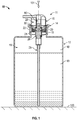
- FIG. 1 showing a foam dispenser 10 having a foaming pump assembly 11 secured to a reservoir 12 containing a foamable fluid 13 to be dispensed.
- the fluid 13 is preferably a liquid.
- the pump assembly 11 includes a piston chamber-forming body 14, a piston-forming element 15 and a diaphragm-forming component 16.
- a dip tube 25 extends from the piston chamber-forming body 14 downwardly into the reservoir 12.
- the reservoir 12 is a non-collapsible reservoir in the sense that as the fluid 13 is drawn from the reservoir 12 by operation of the pump assembly 11 with the discharge of the liquid 13 from the reservoir a vacuum comes to be developed within the reservoir as in the gas 18, being substantially air, in the reservoir 12 above the fluid 13.
- the reservoir 12 defines an interior 19 with the interior 19 enclosed but for having an outlet port 20 formed in a cylindrical externally threaded neck 21 of the reservoir 12.
- the neck 21 of the reservoir 12 is sealably engaged on an internally threaded downwardly extending collar tube 22 on the piston chamber-forming body 14 with a preferred but optional resilient annular seal ring 22 (best seen in Figure 3 ) axially compressed between the outlet port 20 and the piston chamber-forming body 14 to form a seal therebetween.
- each of the piston chamber-forming body 14, the piston-forming element 15 and the diaphragm-forming component 16 is formed as an integral element preferably by injection molding so as to provide the foaming pump assembly 11 from a minimal of parts.
- the pump assembly 11 has merely the dip tube 25, the optional seal ring 22 and a pair of foam inducing screens 23 and 24.
- the three major elements are assembled with the piston-forming element 15 affixed to the diaphragm-forming component 16 and with the piston-forming element 15 and the diaphragm-forming element 16 coupled to the piston chamber-forming body 14 for movement between an extended position as seen in Figure 5 and a retracted position as seen in Figure 6 .
- a liquid pump generally indicated 26 is formed by the interaction of the piston-forming element 15 and the piston chamber-forming body 14 and an air pump generally indicated 28 is formed notably by interaction of the diaphragm-forming component 16 and to the piston chamber-forming body 14.
- the liquid pump 26 discharges the liquid 13 from the reservoir 12 simultaneously with the air pump discharging air such that air and liquid may simultaneously be passed through a foam generator 80 including the foam generating screens 23 and 24 and out a dispensing or discharge outlet 29.
- An air relief valve 30 is provided between the diaphragm-forming component 16 and the piston chamber-forming body 14 to permit atmospheric air to flow from the atmosphere into the interior 19 of the reservoir 12 to relieve any vacuum that may develop within the reservoir 12.
- the piston chamber-forming body 14 is disposed about a central axis 31 and has an axially inner end 32 and an axially outer end 33.
- the piston chamber-forming body 14 includes a center tube 33 disposed coaxially about the axis 31 and open at both axial ends.
- the piston chamber-forming body 14 includes an annular bridge flange 34 which extends radially outwardly from the open upper end of the center tube 33.
- the threaded downwardly extending collar tube 22 extends downwardly from the annular bridge flange 34 coaxially about the center tube 33.
- the annular bridge flange 34 carries an outer tube 36 extending axially outwardly from the annular bridge flange 34 to an axial outer end of the outer tube 36 which carries a radially inwardly extending return flange 38 comprising circumferentially spaced segments.
- the bridge flange 34 provides a radially extending axially outwardly directed upper surface 39.
- the outer tube 36 provides a radially inwardly directed locating surface 40.
- the return flange 38 presents a radially extending axially inwardly directed stopping surface 41 opposed to the axially directed upper surface 39 and spaced axially a first distance D1 as best shown on Figure 7 .
- a plurality of vent passages 42 extend axially through the annular bridge flange 34 from a first opening 43 in the upper surface 39 to a lower opening.
- a number of vent channels 45 are provided, each formed by an axially extending radially inwardly open channelway 46 on the outer tube 36 and a radially extending axially outwardly open radial channelway 47 as seen in Figure 10 .
- the axial channelway 46 is open to the atmosphere at an outer end 37 of the outer tube 36 and communication is provided by the axial channelway 46 and the radial channelway 47 to a radial inner end 49 of the radial channelway 47.
- a stepped fluid chamber 50 is defined having a cylindrical outer chamber 51 and a cylindrical inner chamber 52 with the diameter of the inner chamber 52 being less than the diameter of the outer chamber 51.
- Each chamber is coaxial about the axis 31.
- Each chamber has a cylindrical chamber wall, an inner end and an outer end. The outer end of the inner chamber 52 opens into the inner end of the outer chamber 51.
- An annular shoulder 53 closes the inner end of the inner chamber 51 about the outer end of the outer chamber 52.
- the inner chamber is open at an axial inner end 55 of the fluid chamber 50 into an axially inwardly opening socket 56 at the inner end 32 of the piston chamber-forming body 14 which socket 56 is adapted to secure an upper end of the dip tube 25 such that the dip tube 25 provides communication for fluid 13 from the bottom of the reservoir 12 into the inner chamber 52.
- the piston-forming element 15 is coaxially slidably received within the piston chamber-forming body 14 providing the liquid pump 26 therebetween.
- the configuration of the liquid pump 26 has close similarities to a pump as disclosed in U.S. Patent 5,975,360 .
- the piston-forming element 15 has a central stem 58 from which there extends radially outwardly an annular inner disc 59, an annular intermediate disc 60 and an annular outer disc 61.
- the stem 58 defines internally an axially extending internal passageway 62 extending from an axially inner closed end 63 to an axially outer open end 64.
- Liquid ports 65 extends radially through the central stem 58 providing communication between the internal passageway 62 and the outer chamber 51 axially between the intermediate disc 60 and the outer disc 61.
- the piston-forming element 15 is coaxially slidable relative to the piston chamber-forming body 14 between a retracted position as seen in Figure 5 and an extended position as seen in Figure 6 .
- the piston-forming element 15 is moved relative to the piston chamber-forming body 14 from the extended position to the retracted position in a retraction stroke and from the retracted position to the extended position in a withdrawal stroke.
- the inner disc 59 is maintained within the inner chamber 52 and the intermediate disc 60 and the outer disc 61 are maintained within the outer chamber 51.
- the inner disc 59 with the inner chamber 51 form a first one-way liquid valve 159 permitting liquid flow merely outwardly therebetween.
- the inner disc 59 has an elastically deformable edge portion for engagement with the inner wall of the inner chamber 52.
- the inner disc 59 is biased outwardly into the wall of the inner chamber 52 to prevent fluid flow axially inwardly therepast, however, the inner disc 59 has its end portion deflect radially inwardly away from the wall of the inner chamber 52 to permit fluid flow axially outwardly therepast.
- the outer disc 61 engages the side wall of the outer chamber 51 in a manner to substantially prevent fluid flow axially inwardly or outwardly therepast.
- the intermediate disc 60 has an elastically deformable edge portion which engages the side wall of the outer chamber 51 to substantially prevent fluid flow axially inwardly therepast yet to deflect away from the side wall of the outer chamber 51 to permit fluid to pass axially outwardly therepast.
- the outer disc 61 with the outer chamber 52 form a second one-way liquid valve 161 permitting liquid flow merely outwardly therebetween.
- An annular fluid compartment 66 is defined in the fluid chamber 50 radially between the center tube 33 and the piston-forming element 15 axially between the inner disc 59 and the outer disc 61 with a volume that varies in a stroke of operation with axial movement of the piston-forming element 15 relative to the piston chamber-forming body 14.
- the fluid compartment 66 has a volume in the extended position greater than its volume in the retracted position.
- Operation of the liquid pump 26 is such that in a retraction stroke, the volume of the fluid compartment 66 decreases creating a pressure within the fluid compartment 66 which permits fluid flow radially outwardly past the inner disc 59 and axially outwardly past the intermediate disc 60 such that fluid is discharged axially outwardly past the intermediate disc 60 and via the liquid ports 65 into the internal passageway 62.
- the volume of the liquid compartment 66 increases such that with the intermediate disc 60 preventing fluid flow axially outwardly therepast, the increasing volume in the liquid compartment 66 between the inner disc 59 and the intermediate disc 60 draws fluid from the reservoir 12 axially outwardly past the inner disc 59 from the reservoir 12.
- the piston-forming element 15 includes on its central stem 58 axially outwardly from the outer disc 61 an air port 67 providing for communication from the internal passageway 62 to radially outwardly of the central stem 58 and into an air compartment 68 defined between the diaphragm-forming component 16 and the piston chamber-forming body 14.
- the internal passageway 62 within the central stem 58 includes proximate the outer open end 64 an enlarged foaming chamber 69.
- the inner screen 23 is secured to the central stem 58 to extend across the internal passageway 62 at an axially inner end of the foaming chamber 69 and the outer screen 24 is fixedly secured to the central stem 58 to extend across the internal passageway 62 at the outer open end 64.
- the diaphragm-forming component 16 comprises a flexible annular diaphragm member 70 having at an axially outer end an end cap 71 and an annular flexible diaphragm side wall 72 that extends axially inwardly to an annular first end 73 of the diaphragm member 70.
- the diaphragm member 70 also includes a central tube 74 that extends coaxially about the axis 31.
- the annular first end 73 of the diaphragm member 70 engages on an annular seat arrangement 99 provided on the piston chamber-forming body 14 and formed by the annular bridge flange 34 with its upper surface 39, the outer tube 36 with its locating surface 40 and the return flange 38 with its axially inwardly directed stopping surface 41.
- the central tube 74 has a central bore 75 therein open axially inwardly at a bore inner end 76 and closed at a bore outer end 77.
- the diaphragm member 70 includes a discharge tube 78 that extends radially outwardly on the end cap 71 defining therein a discharge passageway 79 and providing communication from the central bore 75 outwardly to the dispensing or discharge outlet 29 open to the atmosphere.
- a plurality of openings 81 are provided through the side wall 72 of the central tube 74 to provide communication radially through the central tube 74 proximate the bore inner end 76.
- the annular first end 73 of the diaphragm member 70 includes a radially outwardly extending locating flange 82, an air relief valve member 83, a stop foot member 84 and a sealing member 85.
- the piston-forming element 15 and the diaphragm-forming component 16 are fixedly secured together against removal under normal operation of the pump assembly 11 with a radially enlarged outer portion of the central stem 58 about the foaming chamber 69 received in a frictional force-fit relation within the central tube 74 and with the bore inner end 76 engaged on the outer disc 61 of the piston-forming element 15.
- the piston-forming element 15 With the piston-forming element 15 and the diaphragm-forming component 16 fixed together, the piston-forming element 15 is coaxially engaged within the fluid chamber 50 and the diaphragm-forming component 16 is engaged with the piston chamber-forming body 14 with the sealing member 85 and the air relief valve member 83 engaged on the upper surface 39 of the bridge flange 34 and the locating flange 82 disposed axially inwardly of the stopping surface 41 of the return flange 38 as best seen in the enlarged cross-sectional views of Figures 7 to 10 .
- the locating flange 82 includes an axially outwardly directed outer flange stop surface 86 opposed to and, in Figure 7 , engaging the stopping surface 41 on the return flange 38 of the piston chamber-forming body 14 to restrict actual outward movement of the annular first end 73 of the diaphragm member 70 relative to the piston chamber-forming body 14.
- the locating flange 82 is joined at a radially inner end to the diaphragm side wall 72 and extends radially outwardly as an annular flange to a radial distal end 87.
- the air relief valve member 83 comprises an annular disc which extends from an axially outwardly and radially inwardly inner end 88 axially inwardly and radially outwardly to a distal end 89 in engagement with the upper surface 39 of the bridge flange 34.
- the sealing member 85 extends from an axially outwardly and radially outwardly inner end 90 radially inwardly and axially inwardly to a distal end 91 in engagement with the upper surface 39 of the bridge flange 34.
- the stop foot member 84 is provided in between the air relief valve member 83 and the sealing member 85 and extends axially inwardly from an axially outer end 92 to a foot stop surface 93 at a distal end.
- the foot stop surface 93 in the extended position of Figure 7 is spaced axially outwardly from the upper surface 39 an axially a second distance D2, that is, less than the first distance Dl.
- a number of vent ports 95 are provided radially through the stop foot member 84 and provide for communication radially through the stop foot member 84.
- the diaphragm-forming component 16 is preferably formed as an integral member from a resilient material having an inherent bias such that the diaphragm side wall 72 will assume an expanded inherent condition as shown in Figures 1 to 5 .
- the side wall 72 is deflectable from the inherent condition with the inherent bias attempting to return the diaphragm side wall 72 to its inherent condition.
- the air pump 28 is formed with the annular diaphragm member 70 coaxially about the piston-forming element 15 spanning between an axial outer end 94 of the piston-forming element 15 and the piston chamber-forming body 14 to define the annular air compartment 68 therebetween having a variable volume.
- the diaphragm member 70 sealably engages with the piston-forming element 15 by reason of the axially outer end 64 of the central stem 58 being engaged within the central bore 75 of the center tube 74 of the diaphragm member 70 in a sealed and fixed manner.
- the air compartment 68 is defined as an annular space axially between the end cap 71 of the diaphragm-forming component 16 and the bridge flange 34 of the piston chamber-forming body 14 and radially between the diaphragm side wall 72 and the central tube 74.
- the air compartment 68 is in communication with the internal passageway 62 via the air ports 67.
- the air compartment 68 has a volume which varies with displacement of the diaphragm member 70 between the extended position of Figure 5 and the retracted position of Figure 6 .
- a user may apply downwardly directed force 101 onto the end cap 71 the diaphragm-forming component 16 as indicated by the schematic arrow so as to dispense fluid 13 mixed with air as a foam out of the discharge outlet 29 with the movement of the diaphragm-forming component 16 and the piston chamber-forming body 14 together relative to the piston chamber-forming body 14 from the extended position of Figure 5 to the retracted position of Figure 6 .
- the diaphragm side wall 72 deflects from the expanded position of Figure 5 to the compressed and deflated position in Figure 6 and with such deflection of the annular side wall 72, the volume of the air compartment 68 reduces forcing air from the air compartment 68 through the air ports 67 into the internal passageway 62 of the central stem 58 and, hence, to the foam generator 80.
- Such discharge of air via the air pump 28 to the foam generator 80 is simultaneous with the discharge of the fluid 13 via the liquid pump 26 to the foam generator 80 such that the discharged liquid and air will simultaneously be passed through the foam generator 80 and, hence, via the central bore 75 and the discharge passageway 79 to discharge as foam out the discharge outlet 29.
- the inherent bias of the diaphragm side wall 72 urges the diaphragm side wall 72 to assume its inherent configuration as shown in Figure 5 and, in doing so, diaphragm member 70 returns the piston-forming element 15 to the extended position as shown in Figure 5 .
- the inherent resiliency of the diaphragm side wall 72 acts, in effect, as a piston spring member to bias the piston-forming element 15 to the extended position of Figure 5 relative to the piston chamber-forming body 14.
- the volume of the air compartment 68 increases drawing atmospheric air into the air compartment 68 via the discharge outlet 29, the discharge passageway 79, the central bore 75, the internal passageway 62, the air port 67 and the openings 81.
- annular first end 73 of the diaphragm member 70 engages with the annular seat arrangement 99 of the piston chamber-forming body 14 annularly about the piston chamber-forming body 14 for limited reciprocal axial movement of the first end 73 of the diaphragm member 70 relative the annular seat arrangement 99 between an axially outer position shown in Figure 7 and an axially inner position shown in Figure 8 .
- the first end 73 of the diaphragm member 70 is engaged on the annular seat arrangement 99 of the piston chamber-forming body 14 with the locating flange 82 axially disposed between the bridge flange 34 and the return flange 38 with the axially outwardly directed outer flange stop surface 86 on the locating flange 82 in opposition to the axially inwardly directed stopping surface 41 on the return flange 38 so as to limit axial outward movement of the first end 73 of the diaphragm member 70 relative the annular seat arrangement 99 at the axially outer position as seen in Figure 7 .
- the stop foot member 84 has its axially inwardly directed foot stop surface 93 opposed to the upper surface 39 of the bridge flange 34 such that engagement between the foot stop surface 93 and the upper surface 39 of the bridge flange 34 limits axial inward movement of the first end 73 of the diaphragm member 70 in the axially inner position as shown in Figure 8 .
- An annular portion of the upper surface 39 of the bridge flange 34 where the annular foot stop member 84 engages is designated as and provides an axially inwardly directed stopping surface 97.
- the first end 73 of the diaphragm member 70 includes the sealing member 85 which is an annular disc that extends axially inwardly and radially inwardly to the distal end 91 that is in sealed engagement with the upper surface 39 of the bridge flange 34 of the annular seat arrangement 99 of the piston-forming body 14 to form an annular seal 102 preventing flow between the sealing member 85 and the annular seat arrangement 99 in all positions of the first end 73 of the diaphragm member 70 and the annular seat arrangement 99 between the outer position of Figure 7 and the inner position of Figure 8 .
- the sealing member 85 is formed of resilient material and has an inherent bias to adopt an inherent position and when deflected from the inherent position attempts to return to the inherent position.
- the sealing member 85 In moving from the axial outer position of Figure 7 to the axially inner position of Figure 8 , the sealing member 85 is deflected and the distal end 91 displaced marginally radially inwardly on the upper surface 39 yet maintaining the annular seal 102 therewith to prevent fluid flow.
- the distal end 91 of the sealing member 85 engages the upper surface 39 to form the annular seal 102 therewith radially inwardly of the first opening 43 such that the annular seal 102 formed between the sealing member 85 and the upper surface 39 prevents flow into or out of the annular air compartment 68 between the first end 73 of the diaphragm member 70 and the annular seat arrangement 99 of the piston chamber-forming body 14.
- An annular portion of the upper surface 39 of the bridge flange 34 where the sealing member 85 engages is designated as and provides an axially inwardly directed sealing seat surface 197.
- the first end 73 of the diaphragm member 70 carries the air relief valve member 83 which extends axially inwardly and radially outwardly to its distal end 89 which is in engagement with the upper surface 39 of the bridge flange 34.
- the air relief valve member 83 is resilient with an inherent bias to return to an inherent position and when deflected from the inherent position attempts to return to the inherent position.
- the distal end 89 of the air relief valve member 83 is in engagement with the upper surface 39 of the bridge flange 34 in all positions between the outer position of Figure 7 and the inner position of Figure 8 .
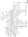
- Figure 9 illustrates the first end 73 of the diaphragm member 70 engaged with the annular seat arrangement 99 of the piston chamber-forming body 14 in an axially outer position the same as that shown in Figure 7 , however, Figure 9 illustrates a cross-section along a radially and axially extending plane indicated as 9-9' in Figure 3 that includes the center axis 31 and passes through the bridge flange 34 through a vent channel 45 and a vent passage 42 and through a segment of the outer tube 36 where the return flange 38 is not provided.
- Figure 10 is a cross-sectional view the same as Figure 9 , however, showing the axially inner position as in Figure 8 .
- the air relief valve member 83 has its distal end 89 engage the upper surface 39 radially inwardly of the radial inner end 49 of the radial channelway 47.
- the distal end 89 of the air relief valve member 83 slides radially outwardly on the upper surface 39 so that a second opening 105 into the radial channelway 47 is provided radially inwardly of the distal end 89 and radially outwardly of the radially inwardly end 49 of the radial channelway 47.
- an air relief passageway generally indicated 106 is defined through the piston liquid chamber-forming body 14 providing communication between external atmospheric air and the interior 19 of the reservoir 12.
- the air relief passageway 106 includes an inner portion generally indicated 107 comprising the vent passage 42 providing communication from its lower opening end 44 through the piston chamber-forming body 14 to the first opening 43 on the upper surface 39 of the annular seat arrangement 99.
- the air relief passageway 106 includes an outer portion generally indicated 108 including the vent channel 45 with its axial channelway 46 and radial channelway 47 providing communication between external atmospheric air and the second opening 105 on the axially outwardly directed upper surface 39.
- the air relief passageway 106 further includes an intermediate portion generally indicated 109 between the first opening 43 and the second opening 105 which, as can be seen in Figure 10 , passes through an annular air relief compartment 110 formed between the sealing member 85 and the air relief valve member 83 and the upper surface 39 and including the vent port 95 through the stop foot member 84.
- the annular air relief compartment 110 as seen in Figure 10 , provides communication between the first opening 43 and the second opening 105.
- the air relief valve member 83 engages the air relief valve seat surface 111 to close and to open the air relief passageway 106 dependent upon the axial position of the first end 73 of the diaphragm member 70 relative the annular seat arrangement 99 between the axially inner position and the axially outer position.
- the air relief valve member 83 engages the air relief valve seat surface 111 of the upper surface 39 so as to open the air relief passageway 106 by providing the second opening 105.
- the air relief valve member 83 has moved radially inwardly of the radial inner end 49 of the radial channelway 47 of the vent channel 45 and engages the air relief valve seat surface 111 of the upper surface 39 in a sealed manner so as to close the air relief passageway 106 by eliminating the second opening 105.
- the interaction of the air relief valve member 83, the air relief valve seat surface 111 and the air relief passageway 106 forms the air relief valve 30 across the air relief passageway 106 that opens and closes the air relief passageway 106 dependent upon the relative axial position of the piston-forming member 15 and the liquid chamber-forming body 14.
- the air relief valve 30 closes the air relief passageway 106 and thus encloses the interior 19 of the reservoir 12.
- the air relief valve 30 opens the air relief passageway 106 so as to permit air from the atmosphere to flow into the interior 19 of the reservoir 12 as to relieve any vacuum condition which may have arisen in the interior 19 due to discharge of the liquid 13 from the reservoir 12 by the liquid pump 26.
- Figures 11 and 12 illustrate a second embodiment of a foaming pump assembly in accordance with the present invention.
- the second embodiment is identical to the first embodiment other than in differences illustrated in Figures 11 and 12 as to the configuration of the first end 73 of the diaphragm member 70 and the annular seat arrangement 99 on the piston chamber-forming body 14.
- the first end 73 has a locating flange 82, an air relief valve member 83 and a sealing member 85 identical to those in the first embodiment, for example, as shown in Figures 9 and 10 .
- a stop foot member 84 is provided which is modified over that of the first embodiment so as to eliminate the vent ports 95.
- the vent passage 42 has been located with its first opening 43 axially in line with the annular stop foot member 84 such that on the foot stop surface 93 engaging the upper surface 39 of the bridge flange 34 in the axially inner position of Figure 12 , the stop foot member 84 closes the first opening 43 and thereby vent passage 42 against flow therethrough.
- the vent channel 45 is provided similar to that shown in Figures 9 and 10 with an axial channelway 46 opening into a radial channelway 47, however, with the difference that the radial inner end 49 of the radial channelway 47 is radially inwardly of the distal end air relief valve member 83 at all times and thus, at all times, the second opening 105 is open into the annular air relief compartment 110.
- the air relief valve 30 is formed between the air relief valve member 83 and the annular seat arrangement 99 providing the air relief passageway 106 to be open permitting communication between the atmospheric air and the interior 19 of the reservoir 12.
- the air relief valve 30 closes the air relief passageway 106.
- the first embodiment is preferred such that when foaming pump assembly 11 is not being used, the air relief valve 30 assists in preventing fluid from the reservoir 12 to flow from the reservoir 12 should, for example, the reservoir 12 be tipped onto its side.
- the major components of the pump assembly 11, namely, the piston chamber-forming body 14, the piston-forming element 15 and the diaphragm-forming component 16 are each formed as an integral element preferably by injection molding.
- the diaphragm-forming component 16 in each of the preferred embodiments is preferably configured so as to facilitate injection molding of the diaphragm-forming component 16 as from a resilient preferably elastomeric matter.
- the arrangement and relative location notably of the valve member 83 and the sealing member 85 provide for advantageous sealing engagement between each of the valve member 83 and the sealing member 85 with the annular seat arrangement 99 merely over axially directed surfaces.
- the diaphragm-forming component 16 may be formed as an integral element. It could be formed from a plurality of elements which are subsequently assembled. Each of the piston chamber-forming body 14 and the piston-forming element 15 which, while preferably are unitary elements, may each be formed from a plurality of elements.
- the diaphragm-forming component 16 and its diaphragm member 70 preferably have sufficient resiliency that from an unassembled condition as illustrated, for example, in Figure 3 , the first end 73 of the diaphragm member 70 can be resiliently deformed so that the locating flange 82 may be manipulated to become engaged axially inwardly of the return flange 38.
- the engagement of the radial distal end 87 of the locating flange 82 with the locating surface 40 of the outer tube 36 of the piston chamber-forming body 14 can assist in preventing radially outward movement of the first end 73 of the diaphragm member 70 as during application of the force 101.
- the piston chamber-forming body 14 is preferably formed from relatively rigid plastic material.
- the return flange 38 is shown in the figures as being a number of circumferentially spaced segments on the outer tube 36 with portions of the outer tube 36 between the return flange segments where the vent channels 45 are provided. Providing the return flange 38 as circumferentially spaced segments can assist in manufacture of the piston chamber-forming body 14, however, is not necessary and the return flange 38 may extend circumferentially about the entirety of the outer tube 36.
- the air vent channel 45 is illustrated as opening upwardly at its axially outer end to the atmosphere. This is not necessary.
- the air vent channel 45 may open to the atmosphere at different locations, for example, as to extend radially outwardly from the radial channelway 47 through the outer tube 36 to the atmosphere as shown in dashed lines as 140 on Figure 11 or through the bridge flange 34 axially inwardly to the atmosphere as shown in dashed lines as 141 on Figure 11 .
- the piston-forming element 15 is preferably shown as an integral element but for the provision of the two foaming screens 23 and 24.
- Each of the foam generating screens 23 and 24 provide small apertures which create turbulence on the simultaneous passage of liquid and air therethrough as is advantageous to provide for preferred foam of the fluid and air.
- the foaming screens 23 and 24 with the foaming chamber 69 provide the foam generator 80 which, in a known manner, provides with the simultaneous passage of the fluid and the air therethrough for the fluid 13 to be mixed with the air and form a foam.
- foam generator 80 may be used, some of which may be formed as integral elements of the piston-forming element 15 and/or diaphragm member 70 without the need for additional elements such as the screens.
- the foam generator 80 is not necessary and, in another embodiment, the screens 23 and 24 may be eliminated and the fluid 13 and the air may be discharged from the discharge outlet 29 as a mixture of the fluid and air, possibly with a nozzle arrangement provided at or upstream of the discharge outlet 29 as to dispersing the liquid into droplets in the air as in a spray or a mist. If desired, arrangements can be provided to separate the fluid discharged from the air discharged until they are directed into the nozzle.
- the piston-forming element 15 is preferably formed as a unitary element from injection molding, this is not necessary and the piston-forming element may be formed from a plurality of elements.
- the liquid pump 26 is illustrated as comprising a stepped pump arrangement so as to minimize the number of components forming the liquid pump 26. Rather than provide the liquid pump 26 to be formed merely between the stepped fluid chamber 50 and the piston-forming element 15, a fluid chamber could be utilized having a constant diameter and a separate one-way inlet valve may be provided between this chamber and the reservoir as in a manner, for example, disclosed in the liquid pump of US7337930 B2 .
- the diaphragm-forming component 16 is illustrated as including and formed with the discharge tube 78.
- the discharge tube 78 may form part of the piston-forming element 15 extending radially from an upper end of the piston-forming element 15 and with the diaphragm-forming component 16 simplified so as to have the central bore 75 extend upwardly through the end cap 17 to an opening for annular engagement about the piston-forming element 15 axially inwardly from the radially outwardly extending discharge tube.
- Such a modified diaphragm-forming component would continue to have a flexible annular diaphragm member coaxially about the piston-forming element 15 spanning between an axial outer piston end of the piston-forming element 15 and the piston chamber-forming body 14 to define a variable volume annular air compartment therebetween.
- the diaphragm member 70 be utilized in a position that the central axis 31 is generally vertical, however, this is not necessary and generally a principal requirement in any oriented use of the pump assembly 11 is that the fluid 13 in the reservoir 12 be at a height below the entranceway in the reservoir 12 to the air relief passageway 106.
- the neck 21 on the reservoir 12 could be located proximate the upper end of the reservoir 12 albeit disposed about a horizontal axis in which case the axis 31 of the embodiment illustrated in Figure 5 would be horizontal and the discharge outlet 29 would discharge fluid liquid downwardly.
- the discharge tube could be modified to be coaxial about the axis 31 and extend horizontally rather than downwardly.
Description
- This invention relates to a pump for simultaneous discharge of liquid and air and, more particularly, to a pump assembly including a liquid pump and an air pump in which the air pump comprises a flexible annular diaphragm member coaxially about a piston-forming element of the liquid pump. In particular, the present invention relates to a foaming pump according to the preamble of independent claim 1.
- Pumps are known for the simultaneous discharge of a liquid from a reservoir bottle and air from the atmosphere. One example of such a pump is shown in
US5271530 . The inventors of the present invention have appreciated that such previously known pumps suffer the disadvantages that they are formed from a large number of parts, and are complex in their manufacture of the different parts leading to increased costs for manufacture and assembly. - The present inventors have appreciated that pumps are known which use diaphragm members, however, it is appreciated that disadvantages arise in respect of the construction of known diaphragm members so as to facilitate their manufacture and advantageous sealing engagement with other elements of the pumps.
CN105 083 730 A teaches an elastic bag foam pump, which comprises a bottle cover (1), an elastic bag (2), a piston rod (3), a piston (4), a liquid inlet one-way valve (6) and a gas inlet one-way valve (8), wherein the elastic bag (2) is a hollow thin-wall bag; the bag opening of the elastic bag is provided with a connection part (2.1); the connection part (2.1) is mounted on an annular wall (1.1) used for connection on the bottle cover (1) in a sealing way; the elastic bag (2) is provided with an inlet hole (1.8) through which an inlet pipe (2.4) is communicated with the bottle cover (1); the gas inlet one-way valve (8) is mounted at one side of the inlet hole (1.8); a piston rod upper end (3.1) is fixed to an upper wall connection part (2.3) of the elastic bag (2); the lower end of the piston rod (3) is provided with the piston (4); and a cylinder (1.2) is arranged in the middle of the bottle cover (1). - The present invention's object is accomplished by the features of the independent claim 1.
- To at least partially overcome some of these disadvantages of the previously known devices, the present invention provides an improved pump assembly incorporating a liquid pump and an air pump and which pump includes a flexible annular diaphragm member coaxially about a piston-forming element forming a component with the liquid pump.
- To at least partially overcome other disadvantages of the previously known devices, the present invention provides a novel arrangement whereby an annular end of a flexible annular diaphragm member of a pump engages with an annular seat arrangement, thus providing a relief valve therebetween to open and close a passageway.
- In one aspect, the present invention provides a pump assembly having a liquid pump comprising a piston-forming element reciprocally axially slidable in a piston liquid chamber-forming body to discharge a liquid from a non-collapsible reservoir and an air pump comprising a flexible annular diaphragm member coaxially about the piston-forming element spanning between the piston-forming element and the piston chamber-forming body for simultaneous discharge of air by the air piston with the discharge of liquid by the liquid piston and in which the diaphragm member engages the piston chamber-forming body to form an air relief valve which open and closes with movement of the diaphragm member to permit external atmosphere air to relieve any vacuum which may arise in the reservoir.
- In another aspect, the present invention provides a pump having a liquid pump comprising a piston-forming element reciprocally axially slidable in a piston liquid chamber-forming body between a retracted position and an extended position defining a liquid compartment therebetween having a variable volume;
an air pump comprising a flexible annular diaphragm member coaxially about the piston-forming element spanning between an axially outer piston end of the piston-forming element and the piston chamber-forming body to define a variable volume annular air compartment therebetween having a variable volume;
a non-collapsible reservoir having an interior containing a fluid to be dispensed, the interior enclosed but for having an outlet port,
the piston liquid chamber-forming body closing the outlet port,
a liquid inlet through the piston liquid chamber-forming body from the interior of the reservoir to the liquid pump,
whereby a retraction stroke of the piston-forming element simultaneously forces air from the air compartment and liquid from the liquid compartment internally through an internal passageway of the piston-forming element and delivers air and liquid from a dispensing outlet carried on the piston-forming element, and
an extension stroke of the piston-forming member simultaneously draws the atmospheric air into the air compartment and the liquid from the interior of the reservoir into the liquid compartment via the liquid inlet,
an air relief passageway through the piston liquid chamber-forming body providing communication between external atmospheric air and the interior of the reservoir,
the diaphragm member engaging the piston liquid chamber-forming body to form therebetween an air relief valve across the air relief passageway to open and to close the air relief passageway dependent on the relative axial position of the piston-forming element and the liquid chamber-forming body. - Preferably, an annular first end of the diaphragm member engages with an annular seat arrangement of the piston chamber-forming body annularly about the piston-forming element for limited reciprocal axial movement of the first end of the diaphragm member relative the annular seat arrangement between an axially inner position and an axially outer position;
the first end of the diaphragm member having a resilient positioning spring member engaging with the annular seat arrangement of the piston chamber-forming body to bias the first end of the diaphragm member from the inner position toward the outer position;
the first end of the diaphragm member having a sealing member engaging the annular seat arrangement of the piston chamber-forming body to form an annular seal preventing flow into and out of the annular air compartment between the sealing member and the annular seat arrangement of the piston chamber-forming body in all positions of the first end of the diaphragm member and the annular seat arrangement between the inner position and the outer position;
the first end of the diaphragm member having an air relief valve member interacting with an air relief valve seat surface of the annular seat arrangement of the piston chamber-forming body to close and to open the air relief passageway dependent on the axial position of the first end of the diaphragm member relative the annular seat arrangement between the inner position and the outer position. - Further aspects and advantages of the present invention will become apparent from the following description taken together with the accompanying drawings in which:
-
Figure 1 is a cross-sectional side view of a foam dispenser in accordance with an embodiment of the present invention; -
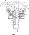
Figure 2 is a cross-sectional pictorial view of the foaming pump assembly of the foam dispenser inFigure 1 in an extended position; -
Figure 3 is a cross-sectiona! exploded perspective view of the pump assembly ofFigure 2 as seen from above; -
Figure 4 is a cross-sectional exploded perspective view of the pump assembly ofFigure 2 as seen from below; -
Figure 5 is a cross-sectional side view of the pump assembly ofFigure 1 in an extended position; -
Figure 6 is a cross-sectional side view the same asFigure 5 but with the pump assembly ofFigure 1 in a retracted position; -
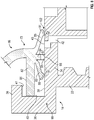
Figure 7 is an enlarged cross-sectional view ofFigure 5 within an oval in dashed lines inFigure 5 ; -
Figure 8 is an enlarged cross-sectional view showing a portion ofFigure 6 within an oval in dashed lines inFigure 6 ; -
Figure 9 is an enlarged cross-sectional view similar toFigure 7 but along a vertical cross-section throughFigure 5 along the radial vertical section line 9-9' shown onFigure 3 ; -
Figure 10 is an enlarged cross-sectional view ofFigure 6 similar toFigure 8 but along a vertical cross-section throughFigure 6 along radial vertical section line 9-9' onFigure 3 ; -
Figure 11 is an enlarged cross-sectional view similar toFigure 9 but showing a second embodiment of a foaming pump assembly in accordance with the present invention in an extended position similar to that shown inFigure 9 ; and -
Figure 12 is an enlarged cross-sectional view similar toFigure 11 but showing another embodiment of the foaming pump assembly ofFigure 11 in a retracted position similar toFigure 10 . - Reference is made to
Figure 1 showing afoam dispenser 10 having afoaming pump assembly 11 secured to areservoir 12 containing afoamable fluid 13 to be dispensed. Thefluid 13 is preferably a liquid. Thepump assembly 11 includes a piston chamber-formingbody 14, a piston-formingelement 15 and a diaphragm-formingcomponent 16. As seen inFigure 1 , adip tube 25 extends from the piston chamber-formingbody 14 downwardly into thereservoir 12. - The
reservoir 12 is a non-collapsible reservoir in the sense that as thefluid 13 is drawn from thereservoir 12 by operation of thepump assembly 11 with the discharge of theliquid 13 from the reservoir a vacuum comes to be developed within the reservoir as in thegas 18, being substantially air, in thereservoir 12 above thefluid 13. - The
reservoir 12 defines aninterior 19 with theinterior 19 enclosed but for having anoutlet port 20 formed in a cylindrical externally threadedneck 21 of thereservoir 12. Theneck 21 of thereservoir 12 is sealably engaged on an internally threaded downwardly extendingcollar tube 22 on the piston chamber-formingbody 14 with a preferred but optional resilient annular seal ring 22 (best seen inFigure 3 ) axially compressed between theoutlet port 20 and the piston chamber-formingbody 14 to form a seal therebetween. - In the preferred embodiment as seen in
Figures 3 and4 , each of the piston chamber-formingbody 14, the piston-formingelement 15 and the diaphragm-formingcomponent 16 is formed as an integral element preferably by injection molding so as to provide thefoaming pump assembly 11 from a minimal of parts. Aside from the major three elements, namely, the piston chamber-formingbody 14, the piston-formingelement 15 and the diaphragm-formingcomponent 16, thepump assembly 11 has merely thedip tube 25, theoptional seal ring 22 and a pair offoam inducing screens - The three major elements are assembled with the piston-forming
element 15 affixed to the diaphragm-formingcomponent 16 and with the piston-formingelement 15 and the diaphragm-formingelement 16 coupled to the piston chamber-formingbody 14 for movement between an extended position as seen inFigure 5 and a retracted position as seen inFigure 6 . - A liquid pump generally indicated 26 is formed by the interaction of the piston-forming
element 15 and the piston chamber-formingbody 14 and an air pump generally indicated 28 is formed notably by interaction of the diaphragm-formingcomponent 16 and to the piston chamber-formingbody 14. In moving from the extended position ofFigure 5 to the retracted position ofFigure 6 , theliquid pump 26 discharges theliquid 13 from thereservoir 12 simultaneously with the air pump discharging air such that air and liquid may simultaneously be passed through afoam generator 80 including the foam generatingscreens discharge outlet 29. Moving from the retracted position ofFigure 6 to the extended position ofFigure 5 , atmospheric air is drawn in by theair pump 28. Anair relief valve 30 is provided between the diaphragm-formingcomponent 16 and the piston chamber-formingbody 14 to permit atmospheric air to flow from the atmosphere into theinterior 19 of thereservoir 12 to relieve any vacuum that may develop within thereservoir 12. - The piston chamber-forming
body 14 is disposed about acentral axis 31 and has an axiallyinner end 32 and an axiallyouter end 33. The piston chamber-formingbody 14 includes acenter tube 33 disposed coaxially about theaxis 31 and open at both axial ends. The piston chamber-formingbody 14 includes anannular bridge flange 34 which extends radially outwardly from the open upper end of thecenter tube 33. The threaded downwardly extendingcollar tube 22 extends downwardly from theannular bridge flange 34 coaxially about thecenter tube 33. Theannular bridge flange 34 carries anouter tube 36 extending axially outwardly from theannular bridge flange 34 to an axial outer end of theouter tube 36 which carries a radially inwardly extendingreturn flange 38 comprising circumferentially spaced segments. Thebridge flange 34 provides a radially extending axially outwardly directedupper surface 39. Theouter tube 36 provides a radially inwardly directed locatingsurface 40. Thereturn flange 38 presents a radially extending axially inwardly directedstopping surface 41 opposed to the axially directedupper surface 39 and spaced axially a first distance D1 as best shown onFigure 7 . A plurality ofvent passages 42 extend axially through theannular bridge flange 34 from afirst opening 43 in theupper surface 39 to a lower opening. At similar circumferential locations to thevent passages 42, a number ofvent channels 45 are provided, each formed by an axially extending radially inwardlyopen channelway 46 on theouter tube 36 and a radially extending axially outwardly openradial channelway 47 as seen inFigure 10 . Theaxial channelway 46 is open to the atmosphere at anouter end 37 of theouter tube 36 and communication is provided by theaxial channelway 46 and theradial channelway 47 to a radialinner end 49 of theradial channelway 47. - Inside the
center tube 33, a steppedfluid chamber 50 is defined having a cylindricalouter chamber 51 and a cylindricalinner chamber 52 with the diameter of theinner chamber 52 being less than the diameter of theouter chamber 51. Each chamber is coaxial about theaxis 31. Each chamber has a cylindrical chamber wall, an inner end and an outer end. The outer end of theinner chamber 52 opens into the inner end of theouter chamber 51. Anannular shoulder 53 closes the inner end of theinner chamber 51 about the outer end of theouter chamber 52. The inner chamber is open at an axialinner end 55 of thefluid chamber 50 into an axially inwardly openingsocket 56 at theinner end 32 of the piston chamber-formingbody 14 whichsocket 56 is adapted to secure an upper end of thedip tube 25 such that thedip tube 25 provides communication forfluid 13 from the bottom of thereservoir 12 into theinner chamber 52. - The piston-forming
element 15 is coaxially slidably received within the piston chamber-formingbody 14 providing theliquid pump 26 therebetween. The configuration of theliquid pump 26 has close similarities to a pump as disclosed inU.S. Patent 5,975,360 . The piston-formingelement 15 has acentral stem 58 from which there extends radially outwardly an annularinner disc 59, an annularintermediate disc 60 and an annularouter disc 61. Thestem 58 defines internally an axially extendinginternal passageway 62 extending from an axially innerclosed end 63 to an axially outeropen end 64.Liquid ports 65 extends radially through thecentral stem 58 providing communication between theinternal passageway 62 and theouter chamber 51 axially between theintermediate disc 60 and theouter disc 61. - The piston-forming
element 15 is coaxially slidable relative to the piston chamber-formingbody 14 between a retracted position as seen inFigure 5 and an extended position as seen inFigure 6 . In a cycle of operation, the piston-formingelement 15 is moved relative to the piston chamber-formingbody 14 from the extended position to the retracted position in a retraction stroke and from the retracted position to the extended position in a withdrawal stroke. During a cycle of operation, theinner disc 59 is maintained within theinner chamber 52 and theintermediate disc 60 and theouter disc 61 are maintained within theouter chamber 51. Theinner disc 59 with theinner chamber 51 form a first one-wayliquid valve 159 permitting liquid flow merely outwardly therebetween. Theinner disc 59 has an elastically deformable edge portion for engagement with the inner wall of theinner chamber 52. Theinner disc 59 is biased outwardly into the wall of theinner chamber 52 to prevent fluid flow axially inwardly therepast, however, theinner disc 59 has its end portion deflect radially inwardly away from the wall of theinner chamber 52 to permit fluid flow axially outwardly therepast. - The
outer disc 61 engages the side wall of theouter chamber 51 in a manner to substantially prevent fluid flow axially inwardly or outwardly therepast. Theintermediate disc 60 has an elastically deformable edge portion which engages the side wall of theouter chamber 51 to substantially prevent fluid flow axially inwardly therepast yet to deflect away from the side wall of theouter chamber 51 to permit fluid to pass axially outwardly therepast. Theouter disc 61 with theouter chamber 52 form a second one-way liquid valve 161 permitting liquid flow merely outwardly therebetween. - An
annular fluid compartment 66 is defined in thefluid chamber 50 radially between thecenter tube 33 and the piston-formingelement 15 axially between theinner disc 59 and theouter disc 61 with a volume that varies in a stroke of operation with axial movement of the piston-formingelement 15 relative to the piston chamber-formingbody 14. Thefluid compartment 66 has a volume in the extended position greater than its volume in the retracted position. Operation of theliquid pump 26 is such that in a retraction stroke, the volume of thefluid compartment 66 decreases creating a pressure within thefluid compartment 66 which permits fluid flow radially outwardly past theinner disc 59 and axially outwardly past theintermediate disc 60 such that fluid is discharged axially outwardly past theintermediate disc 60 and via theliquid ports 65 into theinternal passageway 62. In a withdrawal stroke, the volume of theliquid compartment 66 increases such that with theintermediate disc 60 preventing fluid flow axially outwardly therepast, the increasing volume in theliquid compartment 66 between theinner disc 59 and theintermediate disc 60 draws fluid from thereservoir 12 axially outwardly past theinner disc 59 from thereservoir 12. - The piston-forming
element 15 includes on itscentral stem 58 axially outwardly from theouter disc 61 anair port 67 providing for communication from theinternal passageway 62 to radially outwardly of thecentral stem 58 and into anair compartment 68 defined between the diaphragm-formingcomponent 16 and the piston chamber-formingbody 14. Theinternal passageway 62 within thecentral stem 58 includes proximate the outeropen end 64 an enlarged foaming chamber 69. Theinner screen 23 is secured to thecentral stem 58 to extend across theinternal passageway 62 at an axially inner end of the foaming chamber 69 and theouter screen 24 is fixedly secured to thecentral stem 58 to extend across theinternal passageway 62 at the outeropen end 64. - The diaphragm-forming
component 16 comprises a flexibleannular diaphragm member 70 having at an axially outer end anend cap 71 and an annular flexiblediaphragm side wall 72 that extends axially inwardly to an annularfirst end 73 of thediaphragm member 70. Thediaphragm member 70 also includes acentral tube 74 that extends coaxially about theaxis 31. The annularfirst end 73 of thediaphragm member 70 engages on anannular seat arrangement 99 provided on the piston chamber-formingbody 14 and formed by theannular bridge flange 34 with itsupper surface 39, theouter tube 36 with its locatingsurface 40 and thereturn flange 38 with its axially inwardly directed stoppingsurface 41. Thecentral tube 74 has acentral bore 75 therein open axially inwardly at a boreinner end 76 and closed at a boreouter end 77. - The
diaphragm member 70 includes adischarge tube 78 that extends radially outwardly on theend cap 71 defining therein adischarge passageway 79 and providing communication from thecentral bore 75 outwardly to the dispensing ordischarge outlet 29 open to the atmosphere. A plurality ofopenings 81 are provided through theside wall 72 of thecentral tube 74 to provide communication radially through thecentral tube 74 proximate the boreinner end 76. - As seen on
Figure 7 , the annularfirst end 73 of thediaphragm member 70 includes a radially outwardly extending locatingflange 82, an airrelief valve member 83, astop foot member 84 and a sealingmember 85. - The piston-forming
element 15 and the diaphragm-formingcomponent 16 are fixedly secured together against removal under normal operation of thepump assembly 11 with a radially enlarged outer portion of thecentral stem 58 about the foaming chamber 69 received in a frictional force-fit relation within thecentral tube 74 and with the boreinner end 76 engaged on theouter disc 61 of the piston-formingelement 15. With the piston-formingelement 15 and the diaphragm-formingcomponent 16 fixed together, the piston-formingelement 15 is coaxially engaged within thefluid chamber 50 and the diaphragm-formingcomponent 16 is engaged with the piston chamber-formingbody 14 with the sealingmember 85 and the airrelief valve member 83 engaged on theupper surface 39 of thebridge flange 34 and the locatingflange 82 disposed axially inwardly of the stoppingsurface 41 of thereturn flange 38 as best seen in the enlarged cross-sectional views ofFigures 7 to 10 . As seen inFigure 7 , the locatingflange 82 includes an axially outwardly directed outerflange stop surface 86 opposed to and, inFigure 7 , engaging the stoppingsurface 41 on thereturn flange 38 of the piston chamber-formingbody 14 to restrict actual outward movement of the annularfirst end 73 of thediaphragm member 70 relative to the piston chamber-formingbody 14. The locatingflange 82 is joined at a radially inner end to thediaphragm side wall 72 and extends radially outwardly as an annular flange to a radialdistal end 87. - The air
relief valve member 83 comprises an annular disc which extends from an axially outwardly and radially inwardlyinner end 88 axially inwardly and radially outwardly to adistal end 89 in engagement with theupper surface 39 of thebridge flange 34. - The sealing
member 85 extends from an axially outwardly and radially outwardlyinner end 90 radially inwardly and axially inwardly to adistal end 91 in engagement with theupper surface 39 of thebridge flange 34. - The
stop foot member 84 is provided in between the airrelief valve member 83 and the sealingmember 85 and extends axially inwardly from an axiallyouter end 92 to afoot stop surface 93 at a distal end. - As seen in
Figure 7 , thefoot stop surface 93 in the extended position ofFigure 7 is spaced axially outwardly from theupper surface 39 an axially a second distance D2, that is, less than the first distance Dl. As seen inFigure 7 andFigure 4 , at circumferentially spaced locations, a number ofvent ports 95 are provided radially through thestop foot member 84 and provide for communication radially through thestop foot member 84. - The diaphragm-forming
component 16 is preferably formed as an integral member from a resilient material having an inherent bias such that thediaphragm side wall 72 will assume an expanded inherent condition as shown inFigures 1 to 5 . Theside wall 72 is deflectable from the inherent condition with the inherent bias attempting to return thediaphragm side wall 72 to its inherent condition. Theair pump 28 is formed with theannular diaphragm member 70 coaxially about the piston-formingelement 15 spanning between an axialouter end 94 of the piston-formingelement 15 and the piston chamber-formingbody 14 to define theannular air compartment 68 therebetween having a variable volume. Thediaphragm member 70 sealably engages with the piston-formingelement 15 by reason of the axiallyouter end 64 of thecentral stem 58 being engaged within thecentral bore 75 of thecenter tube 74 of thediaphragm member 70 in a sealed and fixed manner. - With the piston-forming
element 15 and the diaphragm-formingcomponent 16 coupled to the piston chamber-formingbody 14 as shown inFigures 5 and6 , theair compartment 68 is defined as an annular space axially between theend cap 71 of the diaphragm-formingcomponent 16 and thebridge flange 34 of the piston chamber-formingbody 14 and radially between thediaphragm side wall 72 and thecentral tube 74. Theair compartment 68 is in communication with theinternal passageway 62 via theair ports 67. Theair compartment 68 has a volume which varies with displacement of thediaphragm member 70 between the extended position ofFigure 5 and the retracted position ofFigure 6 . - Use of the
foam dispenser 10 as shown inFigure 1 , with thereservoir 12 sitting asupport surface 100, a user with one hand may apply downwardly directedforce 101 onto theend cap 71 the diaphragm-formingcomponent 16 as indicated by the schematic arrow so as to dispense fluid 13 mixed with air as a foam out of thedischarge outlet 29 with the movement of the diaphragm-formingcomponent 16 and the piston chamber-formingbody 14 together relative to the piston chamber-formingbody 14 from the extended position ofFigure 5 to the retracted position ofFigure 6 . Under the application of the axially directedforce 101, thediaphragm side wall 72 deflects from the expanded position ofFigure 5 to the compressed and deflated position inFigure 6 and with such deflection of theannular side wall 72, the volume of theair compartment 68 reduces forcing air from theair compartment 68 through theair ports 67 into theinternal passageway 62 of thecentral stem 58 and, hence, to thefoam generator 80. Such discharge of air via theair pump 28 to thefoam generator 80 is simultaneous with the discharge of the fluid 13 via theliquid pump 26 to thefoam generator 80 such that the discharged liquid and air will simultaneously be passed through thefoam generator 80 and, hence, via thecentral bore 75 and thedischarge passageway 79 to discharge as foam out thedischarge outlet 29. On release of the manually appliedforce 101, from theend cap 71, the inherent bias of thediaphragm side wall 72 urges thediaphragm side wall 72 to assume its inherent configuration as shown inFigure 5 and, in doing so,diaphragm member 70 returns the piston-formingelement 15 to the extended position as shown inFigure 5 . The inherent resiliency of thediaphragm side wall 72 acts, in effect, as a piston spring member to bias the piston-formingelement 15 to the extended position ofFigure 5 relative to the piston chamber-formingbody 14. In movement in the withdrawal stroke from the position ofFigure 6 to the position ofFigure 5 , the volume of theair compartment 68 increases drawing atmospheric air into theair compartment 68 via thedischarge outlet 29, thedischarge passageway 79, thecentral bore 75, theinternal passageway 62, theair port 67 and theopenings 81. - Referring to
Figures 7 and8 , the annularfirst end 73 of thediaphragm member 70 engages with theannular seat arrangement 99 of the piston chamber-formingbody 14 annularly about the piston chamber-formingbody 14 for limited reciprocal axial movement of thefirst end 73 of thediaphragm member 70 relative theannular seat arrangement 99 between an axially outer position shown inFigure 7 and an axially inner position shown inFigure 8 . - As can be seen in
Figure 7 , thefirst end 73 of thediaphragm member 70 is engaged on theannular seat arrangement 99 of the piston chamber-formingbody 14 with the locatingflange 82 axially disposed between thebridge flange 34 and thereturn flange 38 with the axially outwardly directed outerflange stop surface 86 on the locatingflange 82 in opposition to the axially inwardly directed stoppingsurface 41 on thereturn flange 38 so as to limit axial outward movement of thefirst end 73 of thediaphragm member 70 relative theannular seat arrangement 99 at the axially outer position as seen inFigure 7 . Thestop foot member 84 has its axially inwardly directedfoot stop surface 93 opposed to theupper surface 39 of thebridge flange 34 such that engagement between thefoot stop surface 93 and theupper surface 39 of thebridge flange 34 limits axial inward movement of thefirst end 73 of thediaphragm member 70 in the axially inner position as shown inFigure 8 . An annular portion of theupper surface 39 of thebridge flange 34 where the annularfoot stop member 84 engages is designated as and provides an axially inwardly directed stoppingsurface 97. - The
first end 73 of thediaphragm member 70 includes the sealingmember 85 which is an annular disc that extends axially inwardly and radially inwardly to thedistal end 91 that is in sealed engagement with theupper surface 39 of thebridge flange 34 of theannular seat arrangement 99 of the piston-formingbody 14 to form anannular seal 102 preventing flow between the sealingmember 85 and theannular seat arrangement 99 in all positions of thefirst end 73 of thediaphragm member 70 and theannular seat arrangement 99 between the outer position ofFigure 7 and the inner position ofFigure 8 . The sealingmember 85 is formed of resilient material and has an inherent bias to adopt an inherent position and when deflected from the inherent position attempts to return to the inherent position. In moving from the axial outer position ofFigure 7 to the axially inner position ofFigure 8 , the sealingmember 85 is deflected and thedistal end 91 displaced marginally radially inwardly on theupper surface 39 yet maintaining theannular seal 102 therewith to prevent fluid flow. Thedistal end 91 of the sealingmember 85 engages theupper surface 39 to form theannular seal 102 therewith radially inwardly of thefirst opening 43 such that theannular seal 102 formed between the sealingmember 85 and theupper surface 39 prevents flow into or out of theannular air compartment 68 between thefirst end 73 of thediaphragm member 70 and theannular seat arrangement 99 of the piston chamber-formingbody 14. An annular portion of theupper surface 39 of thebridge flange 34 where the sealingmember 85 engages is designated as and provides an axially inwardly directed sealingseat surface 197. In movement of thefirst end 73 of thediaphragm member 70 from the axially outer position ofFigure 7 to the axially inner position ofFigure 8 , the sealingmember 85 is deflected and the inherent bias of the sealingmember 85 will attempt to remove thefirst end 73 of thediaphragm member 70 to the axially outer position ofFigure 7 . - The
first end 73 of thediaphragm member 70 carries the airrelief valve member 83 which extends axially inwardly and radially outwardly to itsdistal end 89 which is in engagement with theupper surface 39 of thebridge flange 34. The airrelief valve member 83 is resilient with an inherent bias to return to an inherent position and when deflected from the inherent position attempts to return to the inherent position. Thedistal end 89 of the airrelief valve member 83 is in engagement with theupper surface 39 of thebridge flange 34 in all positions between the outer position ofFigure 7 and the inner position ofFigure 8 . In axial movement of theouter end 73 of thediaphragm member 70 from the axial outer position ofFigure 7 to the axially inner position ofFigure 8 , thedistal end 89 of the airrelief valve member 83 slides radially outwardly on theupper surface 39 as the airrelief valve member 83 is deflected against its inherent bias. An annular portion of theupper surface 39 of thebridge flange 34 where the airrelief valve member 83 engages is designated as and provides an axially inwardly directed annular air reliefvalve seat surface 111. The inherent bias of the airrelief valve member 83 biases thefirst end 73 of thediaphragm member 70 from the axially inner position ofFigure 8 to the axially outer position ofFigure 7 . - In use of the
foam dispenser 10, when a user applies thedownward force 101 to theend cap 71 as indicated by the schematic arrow inFigure 1 , thefirst end 73 of thediaphragm member 70 is moved from the axially outer position ofFigure 7 to the axially inner position ofFigure 8 during which movement each of the sealingmember 85 and the airrelief valve member 83 are deflected from their inherent position. On release of the downwardly directedforce 101 onto theend cap 71, the inherent bias of each of the sealingmember 85 and the airrelief valve member 83 on thefirst end 73 of thediaphragm member 70 act on theannular seat arrangement 99 to bias thefirst end 73 of thediaphragm member 70 from the axial inner position ofFigure 8 to the axially outer position ofFigure 7 . In this regard, each of the sealingmember 85 and the airrelief valve member 83, individually and collectively, act as a resilient positioning spring member to bias thefirst end 73 from the inner position towards the outer position. - Reference is made to
Figures 9 and10 .Figure 9 illustrates thefirst end 73 of thediaphragm member 70 engaged with theannular seat arrangement 99 of the piston chamber-formingbody 14 in an axially outer position the same as that shown inFigure 7 , however,Figure 9 illustrates a cross-section along a radially and axially extending plane indicated as 9-9' inFigure 3 that includes thecenter axis 31 and passes through thebridge flange 34 through avent channel 45 and avent passage 42 and through a segment of theouter tube 36 where thereturn flange 38 is not provided. -
Figure 10 is a cross-sectional view the same asFigure 9 , however, showing the axially inner position as inFigure 8 . - Referring to
Figure 9 showing the axially outer position, the airrelief valve member 83 has itsdistal end 89 engage theupper surface 39 radially inwardly of the radialinner end 49 of theradial channelway 47. On moving from the axially outer position ofFigure 9 to the axially inner position ofFigure 10 , thedistal end 89 of the airrelief valve member 83 slides radially outwardly on theupper surface 39 so that asecond opening 105 into theradial channelway 47 is provided radially inwardly of thedistal end 89 and radially outwardly of the radially inwardly end 49 of theradial channelway 47. - As can be seen in
Figure 10 , an air relief passageway generally indicated 106 is defined through the piston liquid chamber-formingbody 14 providing communication between external atmospheric air and the interior 19 of thereservoir 12. Theair relief passageway 106 includes an inner portion generally indicated 107 comprising thevent passage 42 providing communication from itslower opening end 44 through the piston chamber-formingbody 14 to thefirst opening 43 on theupper surface 39 of theannular seat arrangement 99. Theair relief passageway 106 includes an outer portion generally indicated 108 including thevent channel 45 with itsaxial channelway 46 andradial channelway 47 providing communication between external atmospheric air and thesecond opening 105 on the axially outwardly directedupper surface 39. Theair relief passageway 106 further includes an intermediate portion generally indicated 109 between thefirst opening 43 and thesecond opening 105 which, as can be seen inFigure 10 , passes through an annularair relief compartment 110 formed between the sealingmember 85 and the airrelief valve member 83 and theupper surface 39 and including thevent port 95 through thestop foot member 84. The annularair relief compartment 110, as seen inFigure 10 , provides communication between thefirst opening 43 and thesecond opening 105. The airrelief valve member 83 engages the air reliefvalve seat surface 111 to close and to open theair relief passageway 106 dependent upon the axial position of thefirst end 73 of thediaphragm member 70 relative theannular seat arrangement 99 between the axially inner position and the axially outer position. - As seen in
Figure 10 in the axial outer position, the airrelief valve member 83 engages the air reliefvalve seat surface 111 of theupper surface 39 so as to open theair relief passageway 106 by providing thesecond opening 105. As seen inFigure 9 in the axial outer position, the airrelief valve member 83 has moved radially inwardly of the radialinner end 49 of theradial channelway 47 of thevent channel 45 and engages the air reliefvalve seat surface 111 of theupper surface 39 in a sealed manner so as to close theair relief passageway 106 by eliminating thesecond opening 105. - The interaction of the air
relief valve member 83, the air reliefvalve seat surface 111 and theair relief passageway 106 forms theair relief valve 30 across theair relief passageway 106 that opens and closes theair relief passageway 106 dependent upon the relative axial position of the piston-formingmember 15 and the liquid chamber-formingbody 14. In the position ofFigure 5 , theair relief valve 30 closes theair relief passageway 106 and thus encloses the interior 19 of thereservoir 12. In the axially inner position ofFigure 6 , theair relief valve 30 opens theair relief passageway 106 so as to permit air from the atmosphere to flow into the interior 19 of thereservoir 12 as to relieve any vacuum condition which may have arisen in the interior 19 due to discharge of the liquid 13 from thereservoir 12 by theliquid pump 26. - Reference is made to
Figures 11 and12 which illustrate a second embodiment of a foaming pump assembly in accordance with the present invention. The second embodiment is identical to the first embodiment other than in differences illustrated inFigures 11 and12 as to the configuration of thefirst end 73 of thediaphragm member 70 and theannular seat arrangement 99 on the piston chamber-formingbody 14. - In
Figures 11 and12 , thefirst end 73 has a locatingflange 82, an airrelief valve member 83 and a sealingmember 85 identical to those in the first embodiment, for example, as shown inFigures 9 and10 . InFigure 11 , astop foot member 84 is provided which is modified over that of the first embodiment so as to eliminate thevent ports 95. - As seen in
Figures 11 and12 , thevent passage 42 has been located with itsfirst opening 43 axially in line with the annularstop foot member 84 such that on thefoot stop surface 93 engaging theupper surface 39 of thebridge flange 34 in the axially inner position ofFigure 12 , thestop foot member 84 closes thefirst opening 43 and thereby ventpassage 42 against flow therethrough. - As seen in
Figures 11 and12 , thevent channel 45 is provided similar to that shown inFigures 9 and10 with anaxial channelway 46 opening into aradial channelway 47, however, with the difference that the radialinner end 49 of theradial channelway 47 is radially inwardly of the distal end airrelief valve member 83 at all times and thus, at all times, thesecond opening 105 is open into the annularair relief compartment 110. In the second embodiment ofFigures 11 and12 , with the foamingpump assembly 11 in an extended position similar to that inFigure 5 , theair relief valve 30 is formed between the airrelief valve member 83 and theannular seat arrangement 99 providing theair relief passageway 106 to be open permitting communication between the atmospheric air and the interior 19 of thereservoir 12. In a retracted position similar to that inFigure 6 , theair relief valve 30 closes theair relief passageway 106. Generally, the first embodiment is preferred such that when foamingpump assembly 11 is not being used, theair relief valve 30 assists in preventing fluid from thereservoir 12 to flow from thereservoir 12 should, for example, thereservoir 12 be tipped onto its side. - In accordance with the preferred embodiments, the major components of the
pump assembly 11, namely, the piston chamber-formingbody 14, the piston-formingelement 15 and the diaphragm-formingcomponent 16 are each formed as an integral element preferably by injection molding. This has the advantage of reducing the number of elements required as is of assistance in reducing the ultimate costs of manufacturing and assembling the resultant product. The diaphragm-formingcomponent 16 in each of the preferred embodiments is preferably configured so as to facilitate injection molding of the diaphragm-formingcomponent 16 as from a resilient preferably elastomeric matter. Particularly, the arrangement and relative location notably of thevalve member 83 and the sealingmember 85 provide for advantageous sealing engagement between each of thevalve member 83 and the sealingmember 85 with theannular seat arrangement 99 merely over axially directed surfaces. - It is not necessary but preferred that the diaphragm-forming
component 16 may be formed as an integral element. It could be formed from a plurality of elements which are subsequently assembled. Each of the piston chamber-formingbody 14 and the piston-formingelement 15 which, while preferably are unitary elements, may each be formed from a plurality of elements. - The diaphragm-forming
component 16 and itsdiaphragm member 70 preferably have sufficient resiliency that from an unassembled condition as illustrated, for example, inFigure 3 , thefirst end 73 of thediaphragm member 70 can be resiliently deformed so that the locatingflange 82 may be manipulated to become engaged axially inwardly of thereturn flange 38. The engagement of the radialdistal end 87 of the locatingflange 82 with the locatingsurface 40 of theouter tube 36 of the piston chamber-formingbody 14 can assist in preventing radially outward movement of thefirst end 73 of thediaphragm member 70 as during application of theforce 101. - In the preferred embodiment, the piston chamber-forming
body 14 is preferably formed from relatively rigid plastic material. - The
return flange 38 is shown in the figures as being a number of circumferentially spaced segments on theouter tube 36 with portions of theouter tube 36 between the return flange segments where thevent channels 45 are provided. Providing thereturn flange 38 as circumferentially spaced segments can assist in manufacture of the piston chamber-formingbody 14, however, is not necessary and thereturn flange 38 may extend circumferentially about the entirety of theouter tube 36. - In the preferred embodiments, the
air vent channel 45 is illustrated as opening upwardly at its axially outer end to the atmosphere. This is not necessary. Theair vent channel 45 may open to the atmosphere at different locations, for example, as to extend radially outwardly from theradial channelway 47 through theouter tube 36 to the atmosphere as shown in dashed lines as 140 onFigure 11 or through thebridge flange 34 axially inwardly to the atmosphere as shown in dashed lines as 141 onFigure 11 . - The piston-forming
element 15 is preferably shown as an integral element but for the provision of the two foamingscreens foam generator 80 which, in a known manner, provides with the simultaneous passage of the fluid and the air therethrough for the fluid 13 to be mixed with the air and form a foam. Various other foam generators may be used, some of which may be formed as integral elements of the piston-formingelement 15 and/ordiaphragm member 70 without the need for additional elements such as the screens. - The provision of the
foam generator 80 is not necessary and, in another embodiment, thescreens discharge outlet 29 as a mixture of the fluid and air, possibly with a nozzle arrangement provided at or upstream of thedischarge outlet 29 as to dispersing the liquid into droplets in the air as in a spray or a mist. If desired, arrangements can be provided to separate the fluid discharged from the air discharged until they are directed into the nozzle. - While the piston-forming
element 15 is preferably formed as a unitary element from injection molding, this is not necessary and the piston-forming element may be formed from a plurality of elements. Theliquid pump 26 is illustrated as comprising a stepped pump arrangement so as to minimize the number of components forming theliquid pump 26. Rather than provide theliquid pump 26 to be formed merely between the steppedfluid chamber 50 and the piston-formingelement 15, a fluid chamber could be utilized having a constant diameter and a separate one-way inlet valve may be provided between this chamber and the reservoir as in a manner, for example, disclosed in the liquid pump ofUS7337930 B2 . - In the preferred embodiments, the diaphragm-forming
component 16 is illustrated as including and formed with thedischarge tube 78. This is a preferred arrangement for providing thepump assembly 11 to have the diaphragm-formingcomponent 16 and the piston-formingelement 15 each formed as a separate integral element and permitting the insertion of thescreens discharge tube 78 may form part of the piston-formingelement 15 extending radially from an upper end of the piston-formingelement 15 and with the diaphragm-formingcomponent 16 simplified so as to have thecentral bore 75 extend upwardly through the end cap 17 to an opening for annular engagement about the piston-formingelement 15 axially inwardly from the radially outwardly extending discharge tube. Such a modified diaphragm-forming component would continue to have a flexible annular diaphragm member coaxially about the piston-formingelement 15 spanning between an axial outer piston end of the piston-formingelement 15 and the piston chamber-formingbody 14 to define a variable volume annular air compartment therebetween. - In accordance with the present invention, it is preferred that the
diaphragm member 70 be utilized in a position that thecentral axis 31 is generally vertical, however, this is not necessary and generally a principal requirement in any oriented use of thepump assembly 11 is that the fluid 13 in thereservoir 12 be at a height below the entranceway in thereservoir 12 to theair relief passageway 106. In one modification of the dispenser as illustrated inFigure 1 , theneck 21 on thereservoir 12 could be located proximate the upper end of thereservoir 12 albeit disposed about a horizontal axis in which case theaxis 31 of the embodiment illustrated inFigure 5 would be horizontal and thedischarge outlet 29 would discharge fluid liquid downwardly. In another variant of such an arrangement, the discharge tube could be modified to be coaxial about theaxis 31 and extend horizontally rather than downwardly. - While the invention has been described with reference to preferred embodiments, many modifications and variations will now occur to a person skilled in the art. For a definition of the invention, reference is made to the following claims.
Claims (16)
- A pump (11) having:a liquid pump (26) comprising a piston-forming element (15) reciprocally axially slidable in a piston chamber-forming body (14) between a retracted position and an extended position defining a liquid compartment (66) therebetween having a variable volume;an air pump (28) comprising a flexible annular diaphragm member (70) coaxially about the piston-forming element (15) spanning between an axially outer piston end (94) of the piston-forming element (15) and the piston chamber-forming body (14) to define a variable volume annular air compartment (68) therebetween having a variable volume;a non-collapsible reservoir (12) having an interior (19) containing a fluid to be dispensed, the interior (19) enclosed but for having an outlet port (20),the piston chamber-forming body (14) closing the outlet port (20),a liquid inlet (56) through the piston chamber-forming body (14) from the interior (19) of the reservoir (12) to the liquid pump,whereby a retraction stroke of the piston forming element simultaneously forces air from the air compartment (68) and liquid from the liquid compartment (66) internally through an internal passageway (62) of the piston-forming element (15) and delivers the air and liquid from a dispensing outlet (29) carried on the piston-forming element (15), andan extension stroke of the piston-forming element (15) simultaneously draws the atmospheric air into the air compartment (68) and the liquid from the interior (19) of the reservoir (12) into the liquid compartment (66) via the liquid inlet (56),characterized by:an air relief passageway (106) through the piston chamber-forming body (14) providing communication between external atmospheric air and the interior (19) of the reservoir (12),:the diaphragm member (70) engaging the piston chamber-forming body (14) to form therebetween an air relief valve (30) across the air relief passageway (106) to open and to close the air relief passageway (106) dependent on the relative axial position of the piston-forming element (15) and the piston chamber-forming body (14).
- A pump as claimed in claim 1 wherein:an annular first end (73) of the diaphragm member (70) engages with an annular seat arrangement (99) of the piston chamber-forming body (14) annularly about the piston-forming element (15) for limited reciprocal axial movement of the first end (73) of the diaphragm member (70) relative the annular seat arrangement (99) between an axially inner position and an axially outer position;the first end (73) of the diaphragm member (70) having a resilient positioning spring member engaging with the annular seat arrangement (99) of the piston chamber-forming body (14) to bias the first end (73) of the diaphragm member (70) from the inner position toward the outer position;the first end of the diaphragm member (70) having a sealing member (85) engaging the annular seat arrangement (99) of the piston chamber-forming body (14) to form an annular seal (102) preventing flow into and out of the annular air compartment (68) between the sealing member (85) and the annular seat arrangement (99) of the piston chamber-forming body (14) in all positions of the first end (73) of the diaphragm member (70) and the annular seat arrangement (99) between the inner position and the outer position;the first end of the diaphragm member (70) having an air relief valve member (83) interacting with an air relief valve seat surface (111) of the annular seat arrangement (99) of the piston chamber-forming body (14) to close and to open the air relief passageway (106) dependent on the axial position of the first end (73) of the diaphragm member (70) relative the annular seat arrangement (99) between the inner position and the outer position.
- A pump as claimed in claim 2 wherein the annular seat arrangement (99) including an axially outwardly directed stop surface (86) and an axially inwardly directed stop surface (41) are opposed to the axially outwardly directed stop surface (86) and spaced axially from the axially outwardly directed stop surface (86) a first axial distance,
the first end (73) of the diaphragm member (70) having an axially outwardly directed stop surface (86) opposed to the axially inwardly directed stop surface (41) of the annular seat arrangement (99) and an axially inwardly directed stop surface (41) opposed to the axially outwardly directed stop surface (86) of the annular seat arrangement (99) and spaced axially from the axially outwardly directed stop surface (86) of the annular seat arrangement (99) a second distance less than the first axial distance,
engagement between the axially outwardly directed stop surface (86) on the annular seat arrangement (99) and the axially inwardly directed stop surface (41) on the first end (73) of the diaphragm member (99) limits movement of the first end (73) of the diaphragm member (70) relative the annular seat arrangement (99) in the inner position; and
engagement between the axially inwardly directed stop surface (41) on the annular seat arrangement (99) and the axially outwardly directed stop surface on the first end (73) of the diaphragm member (70) limits movement of the inner end (73) of the diaphragm member (70) relative the annular seat arrangement (99) in the outer position. - A pump as claimed in claim 2 or 3 wherein:the annular seat arrangement (99) including an axially outwardly directed annular sealing seat surface,the sealing member (85) comprising an annular sealing disc having an axially outer end fixed to the first end (73) of the diaphragm member (70),the annular sealing disc extending axially inwardly from the axially outer end to an annular axially inner distal end of the annular sealing disc,the annular sealing disc being resilient and having an inherent bias urging the distal end of the annular sealing disc into sealed engagement with the axially outwardly directed annular sealing seat surface to form the annular seal (102) preventing air flow between the sealing member (85) and the axially outwardly directed annular sealing seat surface in all positions of the first end (73) of the diaphragm member (70) and the annular seat arrangement (99) between the axially inner position and the axially outer position.
- A pump as claimed in any one of claims 2 to 4 wherein the first end (73) of the diaphragm member (70) is an annular axially inner distal end of the diaphragm member (70).
- A pump as claimed in claim 3 wherein in a first position selected from the inner position and the outer position, the air relief valve member engages the air relief valve seat surface of the annular seat arrangement of the piston chamber-forming body to close the air relief passageway and, in a second position, different than the first position and also selected from the inner position and the outer position, the air relief valve member is located relative the air relief valve seat surface of the annular seat arrangement of the piston chamber-forming body to open the air relief passageway.
- A pump as claimed in any one of claims 2 to 6 including a piston spring member biasing the piston-forming element (15) to the extended position relative the piston chamber-forming body (14), and
the diaphragm member (70) deflectable between an expanded condition in which the piston-forming element (15) is in the extended position relative the piston chamber-forming body (14) and a compressed condition in which the piston-forming element (15) is in the retracted position relative the piston chamber forming body (14),
the volume of the air compartment (66) is greater when the diaphragm member (70) is in the expanded condition than when the diaphragm member (70) is in the compressed condition. - A pump as claimed in claim 7 wherein the diaphragm member (70) having an inherent bias to assume the expanded condition and the inherent bias urges the diaphragm member (70) to return toward the expanded condition when the diaphragm member (70) is moved from the expanded condition toward the compressed condition.
- A pump as claimed in claim 8 wherein the diaphragm member (70) comprises the piston spring member.
- A pump as claimed in any one of claims 7 to 9 wherein the piston spring member biasing the piston-forming element (15) to the extended position urges the first end (73) of the diaphragm member (70) toward the inner position and when the piston-forming element (15) is in the extended position, the inherent bias of the positioning spring member moves the first end (73) of the diaphragm member (70) to the outer position.
- A pump as claimed in any one of claims 7 to 10 wherein the piston spring member urges the first end (73) of the diaphragm member (70) toward the inner position in opposition to the positioning spring member which urges the first end (73) of the diaphragm member (70) toward the outer position, and wherein when the piston-forming element (15) is in the extended position, the positioning spring member overcomes the piston spring member and moves the first end (73) of the diaphragm member (70) to the outer position.
- A pump as claimed in any one of claims 1 to 11 wherein:the diaphragm member (70) having an annular flexible diaphragm side wall (72) extending from a first side wall end at the first end (73) of the diaphragm member (70) to a second side wall end,the diaphragm side wall (72) coaxially disposed about the piston-forming member (15) with the second side wall end of the diaphragm side wall sealably coupled to the outer piston end (94) of the piston-forming element (15) for movement therewith and the first side wall end of the diaphragm side wall (72) coupled to the piston chamber-forming body (14) to define the annular air compartment (68) coaxially about the piston-forming element (15).
- A pump as claimed in claim 12 wherein the diaphragm side wall (72) extends axially outwardly from the first side wall end to the second side wall end, and
the diaphragm side wall extends radially inwardly from the first side wall end to the second side wall end. - A pump as claimed in claim 1 wherein the diaphragm member (70) has a central bore (75) coaxially therethrough coaxially within the second side wall end of the diaphragm side wall (72), the outer piston end (94) of the piston-forming element (15) coaxially sealably engaged in the central bore (75).
- A pump as claimed in claim 14 wherein the diaphragm member (70) carries radially inwardly on the second side wall end of the diaphragm side wall (72) a central tube coaxially with the diaphragm side wall (72) and providing the central bore (75) therethrough,
the outer piston end (94) of the piston-forming element (15) coaxially sealably engaged in the central bore (75),
the central bore (75) having a bore inlet and a bore outlet leading to the dispensing outlet (29),
the outer piston end of the piston-forming element (15) coaxially sealably engaged in the central bore (75) with the internal passageway (82) opening into the central bore (75). - A pump as claimed in any one of claims 1 to 15 including a foam generator (80), wherein the retraction stroke of the piston-forming element (15) simultaneously forces air from the air chamber (68) and liquid from the liquid chamber (66) internally through the internal passageway (62) of the piston-forming element (50) and through the foam generator (80) to produce a foam of the air and the liquid and deliver the foam from the dispensing outlet (29)
Applications Claiming Priority (1)
| Application Number | Priority Date | Filing Date | Title |
|---|---|---|---|
| CA2923827A CA2923827C (en) | 2016-03-15 | 2016-03-15 | Three piece pump |
Publications (2)
| Publication Number | Publication Date |
|---|---|
| EP3219395A1 EP3219395A1 (en) | 2017-09-20 |
| EP3219395B1 true EP3219395B1 (en) | 2020-04-29 |
Family
ID=58347190
Family Applications (1)
| Application Number | Title | Priority Date | Filing Date |
|---|---|---|---|
| EP17161034.8A Active EP3219395B1 (en) | 2016-03-15 | 2017-03-15 | Three piece pump |
Country Status (4)
| Country | Link |
|---|---|
| US (1) | US10434532B2 (en) |
| EP (1) | EP3219395B1 (en) |
| CN (1) | CN107187723B (en) |
| CA (1) | CA2923827C (en) |
Families Citing this family (14)
| Publication number | Priority date | Publication date | Assignee | Title |
|---|---|---|---|---|
| PL2982444T3 (en) * | 2014-08-05 | 2020-05-18 | Goizper, S. Coop. | Pressure spray device |
| DE102016108447A1 (en) * | 2016-05-06 | 2017-11-09 | S O L O Kleinmotoren Gesellschaft Mit Beschränkter Haftung | Foaming unit for producing foam from a mixture of gas and liquid and spray device for producing and distributing foam |
| DE102017108901A1 (en) * | 2017-04-26 | 2018-10-31 | Valeo Wischersysteme Gmbh | Cleaning device for vehicles and method for cleaning surfaces on vehicles |
| CA2984761A1 (en) | 2017-11-06 | 2019-05-06 | Op-Hygiene Ip Gmbh | Fluid storage reservoir |
| US11702274B2 (en) | 2017-11-06 | 2023-07-18 | Op-Hygiene Ip Gmbh | Fluid storage reservoir |
| CN111491682B (en) * | 2017-12-22 | 2024-02-13 | 索芙特海尔公司 | Flexible pump chamber |
| US10335816B1 (en) | 2018-08-29 | 2019-07-02 | Armin Arminak | All plastic water resistant pump |
| EP3736049B1 (en) | 2019-05-06 | 2022-11-09 | Aptar Radolfzell GmbH | Discharge head and liquid dispenser with a discharge head |
| WO2021058284A1 (en) * | 2019-09-23 | 2021-04-01 | Silgan Dispensing Systems Le Treport | Foam dispensing system having multiple valves for a dispenser, and associated foam dispenser |
| USD991785S1 (en) | 2020-01-31 | 2023-07-11 | Armin Arminak | Lotion pump actuator |
| US11389814B1 (en) | 2021-04-16 | 2022-07-19 | Armin Arminak | All plastic hand pump with a piston having an integrated check valve |
| US11471905B1 (en) * | 2021-09-23 | 2022-10-18 | Apackaging Group Llc | All plastic airless pump dispenser |
| WO2023094336A1 (en) * | 2021-11-19 | 2023-06-01 | Rieke Packaging Systems Limited | Single-polymer, reciprocating dispenser for foam products |
| EP4331729A1 (en) * | 2022-08-31 | 2024-03-06 | Aptar Villingen GmbH | Pump module, discharge head and fluid dispenser |
Family Cites Families (15)
| Publication number | Priority date | Publication date | Assignee | Title |
|---|---|---|---|---|
| US3987938A (en) * | 1975-09-18 | 1976-10-26 | Diamond International Corporation | Dispensing pump |
| EP0194417B1 (en) * | 1985-03-14 | 1989-10-04 | MegaPlast Dosiersysteme GmbH & Co. | Metering pump with a pumping bellow for bottles or the like |
| DE69017922T2 (en) | 1990-11-07 | 1995-08-03 | Daiwa Can Co Ltd | Blistering pumping vessel. |
| US5975360A (en) | 1991-05-20 | 1999-11-02 | Ophardt; Heiner | Capped piston pump |
| IT1252216B (en) * | 1991-12-16 | 1995-06-05 | Sar Spa | DISPENSER OF LIQUID SUBSTANCES OR CREAM OR PASTA SUBFORMATION |
| US5664703A (en) * | 1994-02-28 | 1997-09-09 | The Procter & Gamble Company | Pump device with collapsible pump chamber having supply container venting system and integral shipping seal |
| US5462208A (en) | 1994-08-01 | 1995-10-31 | The Procter & Gamble Company | Two-phase dispensing systems utilizing bellows pumps |
| FR2806933B1 (en) * | 2000-03-31 | 2003-04-11 | Oreal | SPRING EFFECT PUSH BUTTON |
| EP1266696A1 (en) | 2001-06-13 | 2002-12-18 | Taplast S.p.A. | Bellows pump for delivery gas-liquid mixtures |
| US7337930B2 (en) | 2005-05-20 | 2008-03-04 | Gotohti.Com Inc. | Foaming pump with improved air inlet valve |
| JP2007137497A (en) | 2005-11-21 | 2007-06-07 | Canyon Corp | Foam discharging type pump dispenser |
| DK2209558T3 (en) * | 2007-11-01 | 2015-04-20 | Pibed Ltd | Device for delivery of fluid |
| US8616414B2 (en) | 2009-02-09 | 2013-12-31 | Gojo Industries, Inc. | Bellows foam dispenser |
| US8814005B2 (en) * | 2012-04-27 | 2014-08-26 | Pibed Limited | Foam dispenser |
| CN105083730B (en) | 2015-06-26 | 2017-07-14 | 钟竞铮 | Elastomeric bladder foam pump |
-
2016
- 2016-03-15 CA CA2923827A patent/CA2923827C/en active Active
-
2017
- 2017-03-14 US US15/458,630 patent/US10434532B2/en active Active
- 2017-03-15 EP EP17161034.8A patent/EP3219395B1/en active Active
- 2017-03-15 CN CN201710154199.7A patent/CN107187723B/en active Active
Non-Patent Citations (1)
| Title |
|---|
| None * |
Also Published As
| Publication number | Publication date |
|---|---|
| CN107187723B (en) | 2020-10-16 |
| EP3219395A1 (en) | 2017-09-20 |
| CA2923827A1 (en) | 2017-09-15 |
| US10434532B2 (en) | 2019-10-08 |
| CA2923827C (en) | 2023-08-01 |
| CN107187723A (en) | 2017-09-22 |
| US20170266680A1 (en) | 2017-09-21 |
Similar Documents
| Publication | Publication Date | Title |
|---|---|---|
| EP3219395B1 (en) | Three piece pump | |
| USRE49597E1 (en) | Valvular conduit | |
| EP1604600B1 (en) | Draw back pump | |
| US6840408B1 (en) | Air foam pump with shifting air piston | |
| US7147133B2 (en) | Foam forming unit | |
| EP2910311B1 (en) | Multiple air chamber foam pump | |
| US11337563B2 (en) | Two-piece foam piston pump | |
| EP3556472B1 (en) | Two stage foam pump and method of producing foam | |
| US11236737B2 (en) | Foam pump and dispenser employing same | |
| US5568886A (en) | Combined turret and closure seal | |
| EP3845104B1 (en) | Stationary outlet stem pump | |
| CA3018299A1 (en) | Two stage foam pump and method of producing foam | |
| EP2785466B1 (en) | Pumping device for a fluid container |
Legal Events
| Date | Code | Title | Description |
|---|---|---|---|
| PUAI | Public reference made under article 153(3) epc to a published international application that has entered the european phase |
Free format text: ORIGINAL CODE: 0009012 |
|
| STAA | Information on the status of an ep patent application or granted ep patent |
Free format text: STATUS: THE APPLICATION HAS BEEN PUBLISHED |
|
| AK | Designated contracting states |
Kind code of ref document: A1 Designated state(s): AL AT BE BG CH CY CZ DE DK EE ES FI FR GB GR HR HU IE IS IT LI LT LU LV MC MK MT NL NO PL PT RO RS SE SI SK SM TR |
|
| AX | Request for extension of the european patent |
Extension state: BA ME |
|
| STAA | Information on the status of an ep patent application or granted ep patent |
Free format text: STATUS: REQUEST FOR EXAMINATION WAS MADE |
|
| 17P | Request for examination filed |
Effective date: 20180320 |
|
| RBV | Designated contracting states (corrected) |
Designated state(s): AL AT BE BG CH CY CZ DE DK EE ES FI FR GB GR HR HU IE IS IT LI LT LU LV MC MK MT NL NO PL PT RO RS SE SI SK SM TR |
|
| RIC1 | Information provided on ipc code assigned before grant |
Ipc: B05B 11/00 20060101AFI20190321BHEP Ipc: B05B 7/00 20060101ALN20190321BHEP |
|
| GRAP | Despatch of communication of intention to grant a patent |
Free format text: ORIGINAL CODE: EPIDOSNIGR1 |
|
| STAA | Information on the status of an ep patent application or granted ep patent |
Free format text: STATUS: GRANT OF PATENT IS INTENDED |
|
| RIC1 | Information provided on ipc code assigned before grant |
Ipc: B05B 11/00 20060101AFI20190408BHEP Ipc: B05B 7/00 20060101ALN20190408BHEP |
|
| INTG | Intention to grant announced |
Effective date: 20190429 |
|
| GRAJ | Information related to disapproval of communication of intention to grant by the applicant or resumption of examination proceedings by the epo deleted |
Free format text: ORIGINAL CODE: EPIDOSDIGR1 |
|
| STAA | Information on the status of an ep patent application or granted ep patent |
Free format text: STATUS: REQUEST FOR EXAMINATION WAS MADE |
|
| INTC | Intention to grant announced (deleted) | ||
| GRAP | Despatch of communication of intention to grant a patent |
Free format text: ORIGINAL CODE: EPIDOSNIGR1 |
|
| STAA | Information on the status of an ep patent application or granted ep patent |
Free format text: STATUS: GRANT OF PATENT IS INTENDED |
|
| RIC1 | Information provided on ipc code assigned before grant |
Ipc: B05B 7/00 20060101ALN20190926BHEP Ipc: B05B 11/00 20060101AFI20190926BHEP |
|
| INTG | Intention to grant announced |
Effective date: 20191025 |
|
| GRAS | Grant fee paid |
Free format text: ORIGINAL CODE: EPIDOSNIGR3 |
|
| GRAA | (expected) grant |
Free format text: ORIGINAL CODE: 0009210 |
|
| STAA | Information on the status of an ep patent application or granted ep patent |
Free format text: STATUS: THE PATENT HAS BEEN GRANTED |
|
| AK | Designated contracting states |
Kind code of ref document: B1 Designated state(s): AL AT BE BG CH CY CZ DE DK EE ES FI FR GB GR HR HU IE IS IT LI LT LU LV MC MK MT NL NO PL PT RO RS SE SI SK SM TR |
|
| REG | Reference to a national code |
Ref country code: GB Ref legal event code: FG4D |
|
| REG | Reference to a national code |
Ref country code: CH Ref legal event code: EP |
|
| REG | Reference to a national code |
Ref country code: DE Ref legal event code: R096 Ref document number: 602017015473 Country of ref document: DE |
|
| REG | Reference to a national code |
Ref country code: AT Ref legal event code: REF Ref document number: 1262509 Country of ref document: AT Kind code of ref document: T Effective date: 20200515 |
|
| REG | Reference to a national code |
Ref country code: IE Ref legal event code: FG4D |
|
| REG | Reference to a national code |
Ref country code: NL Ref legal event code: MP Effective date: 20200429 |
|
| REG | Reference to a national code |
Ref country code: LT Ref legal event code: MG4D |
|
| PG25 | Lapsed in a contracting state [announced via postgrant information from national office to epo] |
Ref country code: IS Free format text: LAPSE BECAUSE OF FAILURE TO SUBMIT A TRANSLATION OF THE DESCRIPTION OR TO PAY THE FEE WITHIN THE PRESCRIBED TIME-LIMIT Effective date: 20200829 Ref country code: NO Free format text: LAPSE BECAUSE OF FAILURE TO SUBMIT A TRANSLATION OF THE DESCRIPTION OR TO PAY THE FEE WITHIN THE PRESCRIBED TIME-LIMIT Effective date: 20200729 Ref country code: PT Free format text: LAPSE BECAUSE OF FAILURE TO SUBMIT A TRANSLATION OF THE DESCRIPTION OR TO PAY THE FEE WITHIN THE PRESCRIBED TIME-LIMIT Effective date: 20200831 Ref country code: LT Free format text: LAPSE BECAUSE OF FAILURE TO SUBMIT A TRANSLATION OF THE DESCRIPTION OR TO PAY THE FEE WITHIN THE PRESCRIBED TIME-LIMIT Effective date: 20200429 Ref country code: SE Free format text: LAPSE BECAUSE OF FAILURE TO SUBMIT A TRANSLATION OF THE DESCRIPTION OR TO PAY THE FEE WITHIN THE PRESCRIBED TIME-LIMIT Effective date: 20200429 Ref country code: GR Free format text: LAPSE BECAUSE OF FAILURE TO SUBMIT A TRANSLATION OF THE DESCRIPTION OR TO PAY THE FEE WITHIN THE PRESCRIBED TIME-LIMIT Effective date: 20200730 Ref country code: FI Free format text: LAPSE BECAUSE OF FAILURE TO SUBMIT A TRANSLATION OF THE DESCRIPTION OR TO PAY THE FEE WITHIN THE PRESCRIBED TIME-LIMIT Effective date: 20200429 |
|
| REG | Reference to a national code |
Ref country code: AT Ref legal event code: MK05 Ref document number: 1262509 Country of ref document: AT Kind code of ref document: T Effective date: 20200429 |
|
| PG25 | Lapsed in a contracting state [announced via postgrant information from national office to epo] |
Ref country code: BG Free format text: LAPSE BECAUSE OF FAILURE TO SUBMIT A TRANSLATION OF THE DESCRIPTION OR TO PAY THE FEE WITHIN THE PRESCRIBED TIME-LIMIT Effective date: 20200729 Ref country code: HR Free format text: LAPSE BECAUSE OF FAILURE TO SUBMIT A TRANSLATION OF THE DESCRIPTION OR TO PAY THE FEE WITHIN THE PRESCRIBED TIME-LIMIT Effective date: 20200429 Ref country code: LV Free format text: LAPSE BECAUSE OF FAILURE TO SUBMIT A TRANSLATION OF THE DESCRIPTION OR TO PAY THE FEE WITHIN THE PRESCRIBED TIME-LIMIT Effective date: 20200429 Ref country code: RS Free format text: LAPSE BECAUSE OF FAILURE TO SUBMIT A TRANSLATION OF THE DESCRIPTION OR TO PAY THE FEE WITHIN THE PRESCRIBED TIME-LIMIT Effective date: 20200429 |
|
| PG25 | Lapsed in a contracting state [announced via postgrant information from national office to epo] |
Ref country code: AL Free format text: LAPSE BECAUSE OF FAILURE TO SUBMIT A TRANSLATION OF THE DESCRIPTION OR TO PAY THE FEE WITHIN THE PRESCRIBED TIME-LIMIT Effective date: 20200429 Ref country code: NL Free format text: LAPSE BECAUSE OF FAILURE TO SUBMIT A TRANSLATION OF THE DESCRIPTION OR TO PAY THE FEE WITHIN THE PRESCRIBED TIME-LIMIT Effective date: 20200429 |
|
| PG25 | Lapsed in a contracting state [announced via postgrant information from national office to epo] |
Ref country code: AT Free format text: LAPSE BECAUSE OF FAILURE TO SUBMIT A TRANSLATION OF THE DESCRIPTION OR TO PAY THE FEE WITHIN THE PRESCRIBED TIME-LIMIT Effective date: 20200429 Ref country code: ES Free format text: LAPSE BECAUSE OF FAILURE TO SUBMIT A TRANSLATION OF THE DESCRIPTION OR TO PAY THE FEE WITHIN THE PRESCRIBED TIME-LIMIT Effective date: 20200429 Ref country code: IT Free format text: LAPSE BECAUSE OF FAILURE TO SUBMIT A TRANSLATION OF THE DESCRIPTION OR TO PAY THE FEE WITHIN THE PRESCRIBED TIME-LIMIT Effective date: 20200429 Ref country code: CZ Free format text: LAPSE BECAUSE OF FAILURE TO SUBMIT A TRANSLATION OF THE DESCRIPTION OR TO PAY THE FEE WITHIN THE PRESCRIBED TIME-LIMIT Effective date: 20200429 Ref country code: RO Free format text: LAPSE BECAUSE OF FAILURE TO SUBMIT A TRANSLATION OF THE DESCRIPTION OR TO PAY THE FEE WITHIN THE PRESCRIBED TIME-LIMIT Effective date: 20200429 Ref country code: SM Free format text: LAPSE BECAUSE OF FAILURE TO SUBMIT A TRANSLATION OF THE DESCRIPTION OR TO PAY THE FEE WITHIN THE PRESCRIBED TIME-LIMIT Effective date: 20200429 Ref country code: EE Free format text: LAPSE BECAUSE OF FAILURE TO SUBMIT A TRANSLATION OF THE DESCRIPTION OR TO PAY THE FEE WITHIN THE PRESCRIBED TIME-LIMIT Effective date: 20200429 Ref country code: DK Free format text: LAPSE BECAUSE OF FAILURE TO SUBMIT A TRANSLATION OF THE DESCRIPTION OR TO PAY THE FEE WITHIN THE PRESCRIBED TIME-LIMIT Effective date: 20200429 |
|
| REG | Reference to a national code |
Ref country code: DE Ref legal event code: R097 Ref document number: 602017015473 Country of ref document: DE |
|
| PG25 | Lapsed in a contracting state [announced via postgrant information from national office to epo] |
Ref country code: SK Free format text: LAPSE BECAUSE OF FAILURE TO SUBMIT A TRANSLATION OF THE DESCRIPTION OR TO PAY THE FEE WITHIN THE PRESCRIBED TIME-LIMIT Effective date: 20200429 Ref country code: PL Free format text: LAPSE BECAUSE OF FAILURE TO SUBMIT A TRANSLATION OF THE DESCRIPTION OR TO PAY THE FEE WITHIN THE PRESCRIBED TIME-LIMIT Effective date: 20200429 |
|
| PLBE | No opposition filed within time limit |
Free format text: ORIGINAL CODE: 0009261 |
|
| STAA | Information on the status of an ep patent application or granted ep patent |
Free format text: STATUS: NO OPPOSITION FILED WITHIN TIME LIMIT |
|
| 26N | No opposition filed |
Effective date: 20210201 |
|
| PG25 | Lapsed in a contracting state [announced via postgrant information from national office to epo] |
Ref country code: SI Free format text: LAPSE BECAUSE OF FAILURE TO SUBMIT A TRANSLATION OF THE DESCRIPTION OR TO PAY THE FEE WITHIN THE PRESCRIBED TIME-LIMIT Effective date: 20200429 |
|
| PG25 | Lapsed in a contracting state [announced via postgrant information from national office to epo] |
Ref country code: MC Free format text: LAPSE BECAUSE OF FAILURE TO SUBMIT A TRANSLATION OF THE DESCRIPTION OR TO PAY THE FEE WITHIN THE PRESCRIBED TIME-LIMIT Effective date: 20200429 |
|
| REG | Reference to a national code |
Ref country code: CH Ref legal event code: PL |
|
| REG | Reference to a national code |
Ref country code: BE Ref legal event code: MM Effective date: 20210331 |
|
| PG25 | Lapsed in a contracting state [announced via postgrant information from national office to epo] |
Ref country code: LI Free format text: LAPSE BECAUSE OF NON-PAYMENT OF DUE FEES Effective date: 20210331 Ref country code: LU Free format text: LAPSE BECAUSE OF NON-PAYMENT OF DUE FEES Effective date: 20210315 Ref country code: CH Free format text: LAPSE BECAUSE OF NON-PAYMENT OF DUE FEES Effective date: 20210331 Ref country code: IE Free format text: LAPSE BECAUSE OF NON-PAYMENT OF DUE FEES Effective date: 20210315 |
|
| PG25 | Lapsed in a contracting state [announced via postgrant information from national office to epo] |
Ref country code: BE Free format text: LAPSE BECAUSE OF NON-PAYMENT OF DUE FEES Effective date: 20210331 |
|
| PGFP | Annual fee paid to national office [announced via postgrant information from national office to epo] |
Ref country code: FR Payment date: 20230329 Year of fee payment: 7 |
|
| PG25 | Lapsed in a contracting state [announced via postgrant information from national office to epo] |
Ref country code: HU Free format text: LAPSE BECAUSE OF FAILURE TO SUBMIT A TRANSLATION OF THE DESCRIPTION OR TO PAY THE FEE WITHIN THE PRESCRIBED TIME-LIMIT; INVALID AB INITIO Effective date: 20170315 |
|
| PGFP | Annual fee paid to national office [announced via postgrant information from national office to epo] |
Ref country code: GB Payment date: 20230329 Year of fee payment: 7 Ref country code: DE Payment date: 20230323 Year of fee payment: 7 |
|
| PG25 | Lapsed in a contracting state [announced via postgrant information from national office to epo] |
Ref country code: CY Free format text: LAPSE BECAUSE OF FAILURE TO SUBMIT A TRANSLATION OF THE DESCRIPTION OR TO PAY THE FEE WITHIN THE PRESCRIBED TIME-LIMIT Effective date: 20200429 |