EP3219244A1 - Hinge for doors of electrical household appliances - Google Patents
Hinge for doors of electrical household appliances Download PDFInfo
- Publication number
- EP3219244A1 EP3219244A1 EP16173590.7A EP16173590A EP3219244A1 EP 3219244 A1 EP3219244 A1 EP 3219244A1 EP 16173590 A EP16173590 A EP 16173590A EP 3219244 A1 EP3219244 A1 EP 3219244A1
- Authority
- EP
- European Patent Office
- Prior art keywords
- door
- hinge
- lever
- kinematic unit
- electrical household
- Prior art date
- Legal status (The legal status is an assumption and is not a legal conclusion. Google has not performed a legal analysis and makes no representation as to the accuracy of the status listed.)
- Granted
Links
- 230000008901 benefit Effects 0.000 description 5
- 230000000694 effects Effects 0.000 description 3
- 230000008878 coupling Effects 0.000 description 2
- 238000010168 coupling process Methods 0.000 description 2
- 238000005859 coupling reaction Methods 0.000 description 2
- 238000010276 construction Methods 0.000 description 1
- 238000009434 installation Methods 0.000 description 1
- 238000005259 measurement Methods 0.000 description 1
- 238000005406 washing Methods 0.000 description 1
Images


Classifications
-
- A—HUMAN NECESSITIES
- A47—FURNITURE; DOMESTIC ARTICLES OR APPLIANCES; COFFEE MILLS; SPICE MILLS; SUCTION CLEANERS IN GENERAL
- A47L—DOMESTIC WASHING OR CLEANING; SUCTION CLEANERS IN GENERAL
- A47L15/00—Washing or rinsing machines for crockery or tableware
- A47L15/42—Details
- A47L15/4251—Details of the casing
- A47L15/4257—Details of the loading door
- A47L15/4261—Connections of the door to the casing, e.g. door hinges
-
- A—HUMAN NECESSITIES
- A47—FURNITURE; DOMESTIC ARTICLES OR APPLIANCES; COFFEE MILLS; SPICE MILLS; SUCTION CLEANERS IN GENERAL
- A47L—DOMESTIC WASHING OR CLEANING; SUCTION CLEANERS IN GENERAL
- A47L15/00—Washing or rinsing machines for crockery or tableware
- A47L15/42—Details
- A47L15/4251—Details of the casing
- A47L15/4257—Details of the loading door
- A47L15/4265—Arrangements of door covering/decoration panels or plinths, e.g. for integrated dishwashers
-
- E—FIXED CONSTRUCTIONS
- E05—LOCKS; KEYS; WINDOW OR DOOR FITTINGS; SAFES
- E05D—HINGES OR SUSPENSION DEVICES FOR DOORS, WINDOWS OR WINGS
- E05D3/00—Hinges with pins
- E05D3/06—Hinges with pins with two or more pins
- E05D3/14—Hinges with pins with two or more pins with four parallel pins and two arms
-
- E—FIXED CONSTRUCTIONS
- E05—LOCKS; KEYS; WINDOW OR DOOR FITTINGS; SAFES
- E05D—HINGES OR SUSPENSION DEVICES FOR DOORS, WINDOWS OR WINGS
- E05D3/00—Hinges with pins
- E05D3/06—Hinges with pins with two or more pins
- E05D3/18—Hinges with pins with two or more pins with sliding pins or guides
-
- E—FIXED CONSTRUCTIONS
- E05—LOCKS; KEYS; WINDOW OR DOOR FITTINGS; SAFES
- E05F—DEVICES FOR MOVING WINGS INTO OPEN OR CLOSED POSITION; CHECKS FOR WINGS; WING FITTINGS NOT OTHERWISE PROVIDED FOR, CONCERNED WITH THE FUNCTIONING OF THE WING
- E05F1/00—Closers or openers for wings, not otherwise provided for in this subclass
- E05F1/08—Closers or openers for wings, not otherwise provided for in this subclass spring-actuated, e.g. for horizontally sliding wings
- E05F1/10—Closers or openers for wings, not otherwise provided for in this subclass spring-actuated, e.g. for horizontally sliding wings for swinging wings, e.g. counterbalance
- E05F1/1041—Closers or openers for wings, not otherwise provided for in this subclass spring-actuated, e.g. for horizontally sliding wings for swinging wings, e.g. counterbalance with a coil spring perpendicular to the pivot axis
- E05F1/105—Closers or openers for wings, not otherwise provided for in this subclass spring-actuated, e.g. for horizontally sliding wings for swinging wings, e.g. counterbalance with a coil spring perpendicular to the pivot axis with a compression spring
- E05F1/1058—Closers or openers for wings, not otherwise provided for in this subclass spring-actuated, e.g. for horizontally sliding wings for swinging wings, e.g. counterbalance with a coil spring perpendicular to the pivot axis with a compression spring for counterbalancing
-
- E—FIXED CONSTRUCTIONS
- E05—LOCKS; KEYS; WINDOW OR DOOR FITTINGS; SAFES
- E05F—DEVICES FOR MOVING WINGS INTO OPEN OR CLOSED POSITION; CHECKS FOR WINGS; WING FITTINGS NOT OTHERWISE PROVIDED FOR, CONCERNED WITH THE FUNCTIONING OF THE WING
- E05F1/00—Closers or openers for wings, not otherwise provided for in this subclass
- E05F1/08—Closers or openers for wings, not otherwise provided for in this subclass spring-actuated, e.g. for horizontally sliding wings
- E05F1/10—Closers or openers for wings, not otherwise provided for in this subclass spring-actuated, e.g. for horizontally sliding wings for swinging wings, e.g. counterbalance
- E05F1/12—Mechanisms in the shape of hinges or pivots, operated by springs
- E05F1/1246—Mechanisms in the shape of hinges or pivots, operated by springs with a coil spring perpendicular to the pivot axis
- E05F1/1253—Mechanisms in the shape of hinges or pivots, operated by springs with a coil spring perpendicular to the pivot axis with a compression spring
- E05F1/1261—Mechanisms in the shape of hinges or pivots, operated by springs with a coil spring perpendicular to the pivot axis with a compression spring for counterbalancing
-
- E—FIXED CONSTRUCTIONS
- E05—LOCKS; KEYS; WINDOW OR DOOR FITTINGS; SAFES
- E05D—HINGES OR SUSPENSION DEVICES FOR DOORS, WINDOWS OR WINGS
- E05D3/00—Hinges with pins
- E05D3/02—Hinges with pins with one pin
- E05D3/022—Hinges with pins with one pin allowing an additional lateral movement, e.g. for sealing
-
- E—FIXED CONSTRUCTIONS
- E05—LOCKS; KEYS; WINDOW OR DOOR FITTINGS; SAFES
- E05Y—INDEXING SCHEME ASSOCIATED WITH SUBCLASSES E05D AND E05F, RELATING TO CONSTRUCTION ELEMENTS, ELECTRIC CONTROL, POWER SUPPLY, POWER SIGNAL OR TRANSMISSION, USER INTERFACES, MOUNTING OR COUPLING, DETAILS, ACCESSORIES, AUXILIARY OPERATIONS NOT OTHERWISE PROVIDED FOR, APPLICATION THEREOF
- E05Y2900/00—Application of doors, windows, wings or fittings thereof
- E05Y2900/30—Application of doors, windows, wings or fittings thereof for domestic appliances
- E05Y2900/302—Application of doors, windows, wings or fittings thereof for domestic appliances for built-in appliances
-
- E—FIXED CONSTRUCTIONS
- E05—LOCKS; KEYS; WINDOW OR DOOR FITTINGS; SAFES
- E05Y—INDEXING SCHEME ASSOCIATED WITH SUBCLASSES E05D AND E05F, RELATING TO CONSTRUCTION ELEMENTS, ELECTRIC CONTROL, POWER SUPPLY, POWER SIGNAL OR TRANSMISSION, USER INTERFACES, MOUNTING OR COUPLING, DETAILS, ACCESSORIES, AUXILIARY OPERATIONS NOT OTHERWISE PROVIDED FOR, APPLICATION THEREOF
- E05Y2900/00—Application of doors, windows, wings or fittings thereof
- E05Y2900/30—Application of doors, windows, wings or fittings thereof for domestic appliances
- E05Y2900/304—Application of doors, windows, wings or fittings thereof for domestic appliances for dishwashers
Definitions
- This invention relates to a hinge for doors of electrical household appliances.
- this invention relates to a hinge for doors of recessed electric household appliances equipped with slidable front panels.
- the overall appearance of the kitchen is overall more uniform, eliminating those discontinuities in appearance which might consist of the parts in view of dishwashers, refrigerators, washing machines and the like.
- doors have been developed containing the control means on the top of the door, so as not to form any obstruction on the front and therefore allow the placing of a decorative front panel which is exactly the same as that of a relative item of containing furniture.
- the aim of this invention is to overcome the drawbacks of the prior art by means of a hinge for doors of electric household appliances equipped with slidable front panels which have a simple structure and practical operation.
- a further aim of this invention is to provide a hinge for doors of electric household appliances equipped with slidable front panels which is at the same time easily assembled and convertible.
- the reference numeral 1 denotes in its entirety a hinge made according to this invention, according to two variant embodiments.
- the hinge 1 according to the invention is designed to be applied to a door 2, illustrated with a dashed line in Figures 2 and 5 , of an electrical household appliance not illustrated, which can be opened or closed by tilting relative to a frame, also not illustrated, of the electrical household appliance.
- a front decorative panel 3 is slidably mounted on the door 2.
- the hinge 1 comprises a first element 4 and a second element 5.
- the first element 4 is fixable, in use, to the frame, not illustrated, of the electrical household appliance whilst the second element 5 is fixable, in use, to the door 2, so as it can be opened and closed by tilting relative to the frame of the electrical household appliance.
- the second element 5 is pivoted to the first element 4 by a first pin 6 to allow reciprocal rotation of the elements 4, 5 about a respective axis of rotation A1.
- the axis of rotation A1 defines the axis of rotation of the door 2 relative to the above-mentioned, and not illustrated, frame of the electrical household appliance.
- the hinge 1 comprises a tie rod 7 pivoting on the second element 5 at its first end 7a.
- the tie rod 7 has a first cam profile 8, the first profile 8 engaging, during the movement of the tie rod 7, with a respective guide member 9 integral with the first element 4.
- the first cam profile 8 is advantageously formed by a respective curved slot 10 formed in the body of the tie rod 7.
- the guide member 9 is advantageously defined by a roller or a pin protruding from a substantially flat wall 4a of the first element 4 and designed to engage inside the curved slot 10 in order to condition the sliding of the latter.
- the hinge 1 also comprises a helical spring 11 and a drive rod 12 of the spring 11, both supported by the first element 4.
- the drive rod 12 is hooked below to the tie rod 7 at a relative second end 7b, opposite the above-mentioned first end 7a.
- the drive rod 12 of the spring 11 is advantageously positioned inside the spring 11 and is connected to the top thereof, in such a way as to compress it at the opening of the second element 5.
- the drive rod 12 has an upper end 12a that is longitudinally opposite the end that is hooked to the tie rod 7, the upper end 12 being designed to engage an upper end coil of the spring 11 in such a way as to compress the spring 11.
- the guide member 9 and the first cam profile 8 are configured in order to condition the action of the spring 11 on the movement of the second element 5.
- the tie rod 7, thanks to the first cam profile 8, makes it possible to modulate the action of the spring 11 according to a predetermined law.
- the hinge 1 comprises a kinematic unit 13 configured to impart to the front decorative panel 3 a movement relative to the door 2 to determine the mutual sliding during the opening of the door 2.
- the kinematic unit 13 comprises a first body 14.
- the first body 14 is made integral to the first element 4 by respective rivets 16.
- the rivets 16, define, for the hinge 1, respective connecting means of the first body 14 to the first element 4.
- the first body 14 of the kinematic unit 13 has a second cam profile 17.
- the second cam profile 17 is advantageously defined by a respective second slot 18 formed in the first the body 14.
- the kinematic unit 13 comprises a second body 15 pivoted on the above-mentioned first body 14.
- the second body 15 has a respective longitudinal guide 19 defined by a third slot 20.
- the kinematic unit 13 comprises a linkage 21 connecting between the above-mentioned first body 14 and second body 15.
- the connecting linkage 21 comprises a first lever L1 and a second lever L2.
- the second lever L2 is pivoted with its top end on the above-mentioned first lever L1 and, with its lower end, on a respective second pin 22 defining also the fulcrum of mutual rotation between the above-mentioned first and second body 14 and 15.
- the first lever L1 has, at a relative first end, a follower unit 23 designed to engage with the above-mentioned second cam profile 17.
- the first lever L1 is connected rotatably to a block 24 slidable along the longitudinal guide 19 made on the second body 15.
- the block 24 supports a bracket 25 integral with the above-mentioned decorative front panel.
- the kinematic unit 13 is configured to determine, following the mutual rotation of the relative first and second bodies 14, 15, a sliding of the block 24 and the bracket 25 connected to it, thereby causing the simultaneous relative sliding between the decorative front panel 3 and the door 2 of the electrical household appliance.
- the kinematic unit 13 comprises a linkage 21 ending with a relative bracket 25.
- the linkage 21 comprises a first lever L1 and a second lever L2.
- the second lever L2 is pivoted with its top end on the above-mentioned first lever L1 and, with its lower end, on a respective second pin 22 integral with the first body 14.
- the first lever L1 has, at a relative first end, a follower unit 23 designed to engage with the above-mentioned second cam profile 17.
- the first lever L1 is connected rotatably to a bracket 25 integral with the above-mentioned decorative front panel.
- the kinematic unit 13 is configured to determine, following the rotation of the second element 5 relative to the first element 4, a sliding of the bracket 25, thereby causing the simultaneous relative sliding between the decorative front panel 3 and the door 2 of the electrical household appliance.
- the linkage 21 of the kinematic unit 13 is configured to drive the movement of the bracket 25 made integral with the decorative front panel 3, thereby determining the relative sliding of the latter with respect to the door 2 of the electrical household appliance.
- FIGS 4 and 9 illustrate the hinge 1, respectively in its first and in its second embodiment, in a partially assembled configuration wherein the kinematic unit 13 is detached from the rest of the components of the hinge 1.
- the hinge 1 operates perfectly and is capable of guaranteeing for the door 2 the same law of motion during the opening, with the only difference that in does not have any means to generate the sliding of a front panel 3 relative to the door 2.
- the hinge 1 according to this invention can be easily modified from a hinge designed to be applied to the doors of electrical household appliances equipped with a decorative front panel mounted slidably to a basic or normal hinge and vice versa.
- Figures 2 and 5 illustrate a succession of steps of opening the door 2, starting from Figure 2 and concluding in Figure 5 .
- the reference T1 denotes a notch on the second element 5 integral with the door 2 whilst a corresponding notch T2 is marked on the decorative front panel 3.
- the notches T1, T2 appear spaced by the corresponding measurement of the relative sliding between the door 2 and the decorative panel 3.
- the first lever L1 using the block 24 which is rendered integral by the bracket 25 to the panel 3, imparts to the latter a movement in a direction D at right angles to the axis A1, in the direction indicated by the arrow S which, thanks to sliding means not illustrated, generates a relative movement between the panel 3 and the door 2.
- bracket 25 is not guided in its sliding movement by any element belonging to the hinge 1; there will also need to be guide members, not illustrated, made in the door 2 of the electrical household appliance and designed to guide the relative sliding of the decorative panel 3 and, if necessary, also the movement of the slide 25.
- the fact that the movement of the lever L1 (which transfers by means of the bracket 25 the sliding movement to the front panel 3) is controlled by the second cam profile 17 allows, by varying the latter, the law of motion of the panel 3 to be varied relative to the door 2.
- the hinge according to the invention allows the variation of the law of sliding of the front panel 3 as a function of the specific requirements, by simply modifying the shape of the second cam profile 17, also keeping unchanged the other parts of the kinematic unit 13.
- the hinge 1 according to the invention achieves the preset aims and brings important advantages.
- the second body 15 of the kinematic unit 13 and the second element 5 have respective contact portions R1, R2 useful for the purposes of correctly assembling the hinge 1.
- a hole 26 (defining the portion R1) whilst on the second body 15 there is a tab 27 (defining the portion R2) protruding in the direction of the second element 5 and designed to be inserted at least partially in the above-mentioned hole 26.
- the assembly of the kinematic unit 13 on the base hinge can even be performed after the base hinge has already been mounted on the electrical household appliance.
- the first body 14 is easily connectable to the first element 4 using a plurality of rivets 16.
- the first element 4 has a substantially flat wall 4a and the movable components of the hinge 1 are all located at an inner face of the substantially flat wall 4a.
- the hinge 1 is protected and enclosed, in the relative part integrated in the frame of the electrical household appliance, between the above-mentioned substantially flat wall 4a of the first element 4 and a substantially flat wall 14a of the first body 14.
- the hinge according to the invention is compact and equipped with a limited number of components with respect to its evolved functionality.
- Another advantage linked to the use of the hinge according to this invention is due to the fact that the block 21 for connecting to the panel, as clearly shown in Figure 4 , is disengaged from the second element 5 and, therefore, can be easily fixed to the decorative panel 3 at any time. Even after the connection of the door 2.
- This opportunity also allows the assembly and adjustment of the door 2 to the frame to be performed during assembly of the electrical household appliance and only subsequently slidably connecting the panel 3 to the door 2 and to the block 24 (or directly to the bracket 25) when the installation of the decorative panel 3 is actually requested.
Landscapes
- Engineering & Computer Science (AREA)
- Mechanical Engineering (AREA)
- Hinges (AREA)
Abstract
Description
- This invention relates to a hinge for doors of electrical household appliances.
- More specifically, this invention relates to a hinge for doors of recessed electric household appliances equipped with slidable front panels.
- In recessed electrical household appliances, that is to say, integrated in modern modular kitchens, it is now typically common practice to provide decorative panels covering the actual doors of the electric household appliances, these panels having the same finish as the rest of the kitchen furniture.
- In this way, the overall appearance of the kitchen is overall more uniform, eliminating those discontinuities in appearance which might consist of the parts in view of dishwashers, refrigerators, washing machines and the like.
- More specifically, in the case of dishwashers, for which advantageously the hinge according to this invention is intended, doors have been developed containing the control means on the top of the door, so as not to form any obstruction on the front and therefore allow the placing of a decorative front panel which is exactly the same as that of a relative item of containing furniture.
- However, a problem has arisen when in the design of the kitchen furniture the height of the lower base has been increasingly reduced, which is located, precisely, under the various elements making up the kitchen.
- In order to transmit, basically, an idea of continuity between the floor and the pieces of furniture which rise from this, many designers have in effect designed solutions for kitchens which eliminate or in any case considerably reduce the extension in height of the base of the modular kitchen furniture, so as to transmit, basically, an idea of continuity between the floor and the pieces of furniture which rise from this.
- Whilst, on the one hand, eliminating the base has without doubt resulted in benefits in terms of appearance, on the other hand it has created not insignificant difficulties in opening, for example, dishwashers.
- Assuming, in effect, a decorative panel fixed to the door of the dishwasher, if, when the machine is closed, it extends substantially as far as the floor (having eliminated the lower base), opening the door would be prevented by the jamming of the panel itself against the floor or against the structure of the dishwasher.
- To overcome this drawback, numerous manufacturers have developed slidable coupling systems between the decorative front panel and the door, also forming special kinematic connections which are able to make the decorative panel slide upwards when the door is opened, thus preventing any interference with the floor.
- However, whilst the main problem may be said to be in practice resolved, in reality the above-mentioned kinematic coupling and connecting systems have resulted in a greater complexity in the assembly of the panels on the electric household appliances as well as significant additional costs.
- In fact, prior art systems have considerable complexities, both in terms of construction and assembly.
- The aim of this invention is to overcome the drawbacks of the prior art by means of a hinge for doors of electric household appliances equipped with slidable front panels which have a simple structure and practical operation.
- A further aim of this invention is to provide a hinge for doors of electric household appliances equipped with slidable front panels which is at the same time easily assembled and convertible.
- The technical features of the invention according to the above-mentioned objects may be easily inferred from the contents of the appended claims, especially claims 1 and 8, and, preferably, any of the claims that depend, either directly or indirectly, on these claims.
- The advantages of the present invention are more apparent from the detailed description which follows, with reference to the accompanying drawings which illustrate a preferred embodiment of the invention provided merely by way of example without restricting the scope of the inventive concept, and in which:
-
Figure 1 is a schematic perspective view of a first embodiment of the hinge according to this invention in a partly open configuration; -
Figures 2 and 3 illustrate the hinge ofFigure 1 in respective schematic side elevation views from a different angle; -
Figure 4 is a schematic perspective view of a detail of the hinge of the previous drawings in a partly disassembled condition; -
Figure 5 is a schematic side elevation view, with some parts transparent, of the first embodiment of the hinge according to the invention in a fully open configuration; -
Figure 6 is a schematic perspective view of the hinge ofFigure 4 ; -
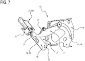
Figure 7 is a schematic perspective view of a detail of the hinge ofFigure 4 , from a different angle; -
Figure 8 is a schematic perspective view of a second embodiment of the hinge according to this invention in a partly open configuration; -
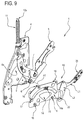
Figure 9 is a schematic perspective view of the hinge ofFigure 8 in a partly disassembled condition; -
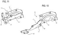
Figures 10 and 11 are schematic perspective views of a detail of the hinge ofFigure 9 , from a different angle, in its two respective open and closed limit configurations. - With reference to the accompanying drawings, the
reference numeral 1 denotes in its entirety a hinge made according to this invention, according to two variant embodiments. - The
hinge 1 according to the invention is designed to be applied to adoor 2, illustrated with a dashed line inFigures 2 and5 , of an electrical household appliance not illustrated, which can be opened or closed by tilting relative to a frame, also not illustrated, of the electrical household appliance. - Again with reference to
Figures 2 and5 , a frontdecorative panel 3 is slidably mounted on thedoor 2. - With reference to both the embodiments illustrated, the
hinge 1 according to the invention comprises afirst element 4 and asecond element 5. - The
first element 4 is fixable, in use, to the frame, not illustrated, of the electrical household appliance whilst thesecond element 5 is fixable, in use, to thedoor 2, so as it can be opened and closed by tilting relative to the frame of the electrical household appliance. - The
second element 5 is pivoted to thefirst element 4 by afirst pin 6 to allow reciprocal rotation of theelements - The axis of rotation A1 defines the axis of rotation of the
door 2 relative to the above-mentioned, and not illustrated, frame of the electrical household appliance. - The
hinge 1 comprises atie rod 7 pivoting on thesecond element 5 at itsfirst end 7a. - The
tie rod 7 has afirst cam profile 8, thefirst profile 8 engaging, during the movement of thetie rod 7, with arespective guide member 9 integral with thefirst element 4. - The
first cam profile 8 is advantageously formed by a respectivecurved slot 10 formed in the body of thetie rod 7. - The
guide member 9 is advantageously defined by a roller or a pin protruding from a substantiallyflat wall 4a of thefirst element 4 and designed to engage inside thecurved slot 10 in order to condition the sliding of the latter. - The
hinge 1 also comprises ahelical spring 11 and adrive rod 12 of thespring 11, both supported by thefirst element 4. - The
drive rod 12 is hooked below to thetie rod 7 at a relativesecond end 7b, opposite the above-mentionedfirst end 7a. - The
drive rod 12 of thespring 11 is advantageously positioned inside thespring 11 and is connected to the top thereof, in such a way as to compress it at the opening of thesecond element 5. - In other words, the
drive rod 12 has anupper end 12a that is longitudinally opposite the end that is hooked to thetie rod 7, theupper end 12 being designed to engage an upper end coil of thespring 11 in such a way as to compress thespring 11. - The
guide member 9 and thefirst cam profile 8 are configured in order to condition the action of thespring 11 on the movement of thesecond element 5. - In other words, during the angular movement of the
second element 5 relative to thefirst element 4, thetie rod 7, thanks to thefirst cam profile 8, makes it possible to modulate the action of thespring 11 according to a predetermined law. - As illustrated in the accompanying drawings, the
hinge 1 comprises akinematic unit 13 configured to impart to the front decorative panel 3 a movement relative to thedoor 2 to determine the mutual sliding during the opening of thedoor 2. - The
kinematic unit 13 comprises afirst body 14. - The
first body 14 is made integral to thefirst element 4 byrespective rivets 16. - The
rivets 16, define, for thehinge 1, respective connecting means of thefirst body 14 to thefirst element 4. - The
first body 14 of thekinematic unit 13 has asecond cam profile 17. Thesecond cam profile 17 is advantageously defined by a respectivesecond slot 18 formed in the first thebody 14. - With reference to the first embodiment illustrated in
Figures 1 to 7 , thekinematic unit 13 comprises asecond body 15 pivoted on the above-mentionedfirst body 14. - The
second body 15 has a respective longitudinal guide 19 defined by a third slot 20. - The
kinematic unit 13 comprises alinkage 21 connecting between the above-mentionedfirst body 14 andsecond body 15. - The connecting
linkage 21 comprises a first lever L1 and a second lever L2. - The second lever L2 is pivoted with its top end on the above-mentioned first lever L1 and, with its lower end, on a respective
second pin 22 defining also the fulcrum of mutual rotation between the above-mentioned first andsecond body - The first lever L1 has, at a relative first end, a
follower unit 23 designed to engage with the above-mentionedsecond cam profile 17. - At its second end opposite the above-mentioned first end, the first lever L1 is connected rotatably to a
block 24 slidable along the longitudinal guide 19 made on thesecond body 15. - The
block 24 supports abracket 25 integral with the above-mentioned decorative front panel. - The
kinematic unit 13 is configured to determine, following the mutual rotation of the relative first andsecond bodies block 24 and thebracket 25 connected to it, thereby causing the simultaneous relative sliding between thedecorative front panel 3 and thedoor 2 of the electrical household appliance. - With reference to the second embodiment illustrated in
Figures 8 to 11 , thekinematic unit 13 comprises alinkage 21 ending with arelative bracket 25. Thelinkage 21 comprises a first lever L1 and a second lever L2. - The second lever L2 is pivoted with its top end on the above-mentioned first lever L1 and, with its lower end, on a respective
second pin 22 integral with thefirst body 14. - The first lever L1 has, at a relative first end, a
follower unit 23 designed to engage with the above-mentionedsecond cam profile 17. - At a relative second end opposite the above-mentioned first end, the first lever L1 is connected rotatably to a
bracket 25 integral with the above-mentioned decorative front panel. - The
kinematic unit 13 is configured to determine, following the rotation of thesecond element 5 relative to thefirst element 4, a sliding of thebracket 25, thereby causing the simultaneous relative sliding between thedecorative front panel 3 and thedoor 2 of the electrical household appliance. - In short, with reference to both the embodiments illustrated and described above, the
linkage 21 of thekinematic unit 13 is configured to drive the movement of thebracket 25 made integral with thedecorative front panel 3, thereby determining the relative sliding of the latter with respect to thedoor 2 of the electrical household appliance. -
Figures 4 and9 illustrate thehinge 1, respectively in its first and in its second embodiment, in a partially assembled configuration wherein thekinematic unit 13 is detached from the rest of the components of thehinge 1. In this configuration, showing an example of the absence of thekinematic unit 13, thehinge 1 operates perfectly and is capable of guaranteeing for thedoor 2 the same law of motion during the opening, with the only difference that in does not have any means to generate the sliding of afront panel 3 relative to thedoor 2. - The fact of being able to apply or not apply the
kinematic unit 13 to thehinge 1 is allowed by the presence, on thehinge 1, ofmeans 16 for connecting thekinematic unit 13 and that thekinematic unit 13 is kinematically disconnected from the others components of thehinge 1. - Therefore, advantageously, the
hinge 1 according to this invention can be easily modified from a hinge designed to be applied to the doors of electrical household appliances equipped with a decorative front panel mounted slidably to a basic or normal hinge and vice versa. - With reference to the first embodiment described,
Figures 2 and5 illustrate a succession of steps of opening thedoor 2, starting fromFigure 2 and concluding inFigure 5 . - As may be clearly inferred from
Figures 2 and5 , during the opening of thedoor 2, the tilting movement of thesecond element 5 relative to thefirst element 4 of thehinge 1, results in, due to the shape and arrangement of the first andsecond bodies front panel 3 relative to thedoor 2. - In
Figure 2 the reference T1 denotes a notch on thesecond element 5 integral with thedoor 2 whilst a corresponding notch T2 is marked on the decorativefront panel 3. InFigure 5 , in which the hinge is shown in a relative open configuration, the notches T1, T2 appear spaced by the corresponding measurement of the relative sliding between thedoor 2 and thedecorative panel 3. - During the opening of the
door 2, the first lever L1, using theblock 24 which is rendered integral by thebracket 25 to thepanel 3, imparts to the latter a movement in a direction D at right angles to the axis A1, in the direction indicated by the arrow S which, thanks to sliding means not illustrated, generates a relative movement between thepanel 3 and thedoor 2. - The operation of the
hinge 1 made in accordance with the second embodiment illustrated inFigures 8 to 11 is substantially similar to that just described with reference to the first embodiment, to which reference is therefore made. - The only significant difference is given by the fact that the
bracket 25 is not guided in its sliding movement by any element belonging to thehinge 1; there will also need to be guide members, not illustrated, made in thedoor 2 of the electrical household appliance and designed to guide the relative sliding of thedecorative panel 3 and, if necessary, also the movement of theslide 25. - Advantageously, the fact that the movement of the lever L1 (which transfers by means of the
bracket 25 the sliding movement to the front panel 3) is controlled by thesecond cam profile 17 allows, by varying the latter, the law of motion of thepanel 3 to be varied relative to thedoor 2. - In other words, the hinge according to the invention allows the variation of the law of sliding of the
front panel 3 as a function of the specific requirements, by simply modifying the shape of thesecond cam profile 17, also keeping unchanged the other parts of thekinematic unit 13. - The
hinge 1 according to the invention achieves the preset aims and brings important advantages. - The fact that the parts of the
hinge 1 acting on thedecorative panel 3, that is to say, thekinematic unit 13, are basically separate from those involved in the tilting movement of thedoor 2, that is to say, thetie rod 7 and thesecond element 5, allows the forces acting on thekinematic unit 13 to be significantly limited which, in practice, is almost completely unloaded, relative to the resultant acting on thehinge 1, of the elastic forces (of the spring 11) and weight (of thedoor 2 and decorative panel 3). - Advantageously, in the embodiment illustrated in
Figures 1 to 7 , thesecond body 15 of thekinematic unit 13 and thesecond element 5 have respective contact portions R1, R2 useful for the purposes of correctly assembling thehinge 1. - More in detail, on the
second element 5 there is a hole 26 (defining the portion R1) whilst on thesecond body 15 there is a tab 27 (defining the portion R2) protruding in the direction of thesecond element 5 and designed to be inserted at least partially in the above-mentioned hole 26. - Thanks to the above mentioned contact portions R1, R2, the assembly of the
hinge 1 appears facilitated, as the perfect mutual positioning of thesecond body 15 and thesecond element 5 is guaranteed. - In other words, the assembly of the
kinematic unit 13 on the base hinge can even be performed after the base hinge has already been mounted on the electrical household appliance. In effect, thefirst body 14 is easily connectable to thefirst element 4 using a plurality ofrivets 16. - The latter advantage also characterises the second embodiment of
Figures 8-11 , wherein thekinematic unit 13, here comprising exclusively thefirst body 14 and thelinkage 21, does not require any connection to thesecond element 5 during assembly of the hinge. - With reference to both the embodiments described and as illustrated in the accompanying drawings, the
first element 4 has a substantiallyflat wall 4a and the movable components of thehinge 1 are all located at an inner face of the substantiallyflat wall 4a. - Advantageously, in this way, when the
kinematic unit 13 is installed, thehinge 1 is protected and enclosed, in the relative part integrated in the frame of the electrical household appliance, between the above-mentioned substantiallyflat wall 4a of thefirst element 4 and a substantiallyflat wall 14a of thefirst body 14. - Also, the hinge according to the invention is compact and equipped with a limited number of components with respect to its evolved functionality.
- Another advantage linked to the use of the hinge according to this invention is due to the fact that the
block 21 for connecting to the panel, as clearly shown inFigure 4 , is disengaged from thesecond element 5 and, therefore, can be easily fixed to thedecorative panel 3 at any time. Even after the connection of thedoor 2. - This opportunity also allows the assembly and adjustment of the
door 2 to the frame to be performed during assembly of the electrical household appliance and only subsequently slidably connecting thepanel 3 to thedoor 2 and to the block 24 (or directly to the bracket 25) when the installation of thedecorative panel 3 is actually requested.
Claims (12)
- A hinge for doors (2) of electrical household appliances provided with a decorative front panel (3) slidably mounted relative to the door (2) along a direction which is orthogonal to an axis of rotation (A1) of the door, comprising,- a first element (4) which is fixable, in use, to the frame of the electrical household appliance and- a second element (5) pivoted on the first element by means of a respective first pin (6) and which is fixable, in use, to the door (2) so that the door (2) can be opened or closed by tilting relative to the frame of the electrical household appliance,- a tie rod (7) pivoted on the second element (5) and having a respective first cam profile (8), the first cam profile (8) engaging with a guide member (9) which is integral with the first element (4),- elastic means (11) operatively coupled to the tie rod (7) for applying, in use, a retaining action on the door (2) during the movement of the door (2) itself from a closed position to an open position,- a kinematic unit (13) configured to impart, to a front decorative panel (3), a movement relative to the door (2) to determine their mutual sliding, characterised in that the kinematic unit (13) comprises at least a first body (14) which is integral with the first element (4) and a connecting linkage (21) configured for controlling the movement of a bracket (25) which is integral with the decorative front panel (3).
- The hinge according to claim 1, characterised in the linkage (21) comprises a first lever (L1) and a second lever (L2), the second lever (L2) being pivoted on the first lever (L1) and on a respective second pin (22) integral with the first body (14).
- The hinge according to claim 2, wherein the first body (14) of the kinematic unit has a respective second cam profile (17), characterised in that the first lever (L1) has a follower member (23) designed to engage with the second cam profile (17).
- The hinge according to claim 3, characterised in that the follower member (23) is positioned at a first longitudinal end of the first lever (L1) and in that the first lever (L1) is connected to the bracket (25) which is integral with the panel (3) at its second longitudinal end opposite to the first end.
- The hinge according to any of claims 2 to 4, characterised in that the first lever (L1), second lever (L2) and tie rod (7) are enclosed between a substantially flat wall (14a) of the first body (14) and a substantially flat wall (4a) of the first element (4).
- The hinge according to any one of the preceding claims, characterised in that the first pin (6) and the second pin (22) are positioned coaxial to each other.
- The hinge according to any one of the preceding claims, characterised in that the kinematic unit (13) comprises at least a second body (15) pivoted on the first body (14) and having a respective longitudinal guide (19), and a linkage (21) connecting between the first and the second body (14, 15), the bracket (25) being slidable along the longitudinal guide (19).
- The hinge according to any one of the preceding claims, characterised in that the longitudinal guide (19) is defined by a slot (20) made in the second body (15).
- The hinge according to claim 8, characterised in that it comprises a block (24) which is slidably engaged in the slot (20), the bracket (25) being supported by the block (24).
- The hinge according to any one of the preceding claims, characterised in that it comprises means (16) for permanently connecting the first body (14) to the first element (4) to form the connection of the kinematic unit (13) to the hinge itself.
- A method for making a hinge for doors (2) of electrical household appliances provided with a decorative front panel (3) according to any one of the preceding claims, starting from a base hinge comprising a first element (4) which is fixable, in use, to the frame of the electrical household appliance, a second element (5) pivoted on the first element through a respective first pin (6) and which is fixable, in use, to the door (2), a tie rod (7) pivoted on the second element (5) and having a respective first cam profile (8), the first cam profile (8) engaging with a guide member (9) which is integral with the first element (4), and elastic means (11) operatively coupled to the first lever (7), the base hinge being designed to allow the tilting movement of the door (2) relative to the frame, comprising the steps of:- preparing the base hinge,- preparing a kinematic unit (13) configured to impart, to a decorative front panel (3), a movement relative to the door (2) to determine their mutual sliding,- permanently connecting a part of the kinematic unit (13) to the first element (4).
- The method according to claim 10, characterised in that the permanent connection step comprises the step of riveting a part of the kinematic unit (13) to the first element (4).
Applications Claiming Priority (1)
| Application Number | Priority Date | Filing Date | Title |
|---|---|---|---|
| ITUA2016A001650A ITUA20161650A1 (en) | 2016-03-14 | 2016-03-14 | HINGE FOR HOUSEHOLD DOORS. |
Publications (2)
| Publication Number | Publication Date |
|---|---|
| EP3219244A1 true EP3219244A1 (en) | 2017-09-20 |
| EP3219244B1 EP3219244B1 (en) | 2021-12-22 |
Family
ID=56203703
Family Applications (1)
| Application Number | Title | Priority Date | Filing Date |
|---|---|---|---|
| EP16173590.7A Active EP3219244B1 (en) | 2016-03-14 | 2016-06-08 | Hinge for doors of electrical household appliances |
Country Status (3)
| Country | Link |
|---|---|
| US (1) | US10244920B2 (en) |
| EP (1) | EP3219244B1 (en) |
| IT (1) | ITUA20161650A1 (en) |
Cited By (2)
| Publication number | Priority date | Publication date | Assignee | Title |
|---|---|---|---|---|
| EP3928675A4 (en) * | 2019-02-18 | 2022-11-16 | LG Electronics Inc. | Dishwasher |
| EP4306752A1 (en) * | 2022-07-12 | 2024-01-17 | C.M.I. Cerniere Meccaniche Industriali S.r.L. | Hinge device for moving a decorative panel |
Families Citing this family (10)
| Publication number | Priority date | Publication date | Assignee | Title |
|---|---|---|---|---|
| SI3259425T1 (en) * | 2015-02-17 | 2020-08-31 | Arturo Salice S.P.A. | Lifting system for leaves of furniture |
| DE102015117291C5 (en) * | 2015-10-09 | 2020-03-26 | Samet Kalip Ve Maden Esya San. Ve Tic. A.S. | Flap holder for a furniture flap |
| IT201700028318A1 (en) * | 2017-03-14 | 2018-09-14 | C M I Cerniere Mecc Industriali Srl | MOTORIZED HINGE DEVICE |
| US11391074B2 (en) * | 2018-06-04 | 2022-07-19 | Viking Range Llc | Door hinge and storage unit including such a door hinge |
| US11072952B2 (en) * | 2019-03-06 | 2021-07-27 | Bsh Home Appliances Corporation | Side opening door keeper |
| KR102241346B1 (en) * | 2020-05-21 | 2021-04-16 | 서원코리아 주식회사 | Door hinge |
| IT202000031142A1 (en) * | 2020-12-16 | 2022-06-16 | Nuova Star Spa | HINGE FOR DOORS |
| EP4180598A1 (en) * | 2021-11-11 | 2023-05-17 | Foshan Shunde Midea Washing Appliances Mfg. Co., Ltd. | Hinge and electrical device |
| EP4242404A1 (en) * | 2022-03-09 | 2023-09-13 | Foshan Shunde Midea Washing Appliances Mfg. Co., Ltd. | Hinge and electrical device |
| US11746579B1 (en) * | 2022-04-08 | 2023-09-05 | The Boeing Company | Hinge assembly and stackable hinge assembly for rotation about an opening |
Citations (1)
| Publication number | Priority date | Publication date | Assignee | Title |
|---|---|---|---|---|
| EP2407723A1 (en) * | 2010-07-14 | 2012-01-18 | Electrolux Home Products Corporation N.V. | Sliding hinge for a domestic appliance |
Family Cites Families (6)
| Publication number | Priority date | Publication date | Assignee | Title |
|---|---|---|---|---|
| US6622345B2 (en) * | 2001-05-29 | 2003-09-23 | Hoshizaki America, Inc. | Door hinge mechanism |
| DE602006012830D1 (en) | 2006-08-31 | 2010-04-22 | Bonferraro Spa | Domestic appliance with front plate arranged on the appliance door |
| EP2116167B1 (en) * | 2008-05-08 | 2011-09-28 | Electrolux Home Products Corporation N.V. | Dishwasher with dampening means for dampening the closing of the door |
| US8266765B2 (en) * | 2009-03-11 | 2012-09-18 | Electrolux Home Products, Inc. | Appliance door hinge |
| PL2453091T3 (en) * | 2010-11-11 | 2016-09-30 | Hinge assembly for household appliances having an horizontally-pivoted front door | |
| ITBO20120273A1 (en) * | 2012-05-17 | 2013-11-18 | Cmi Srl | BALANCED HINGE DEVICE WITH PROGRAMMABLE BRAKE |
-
2016
- 2016-03-14 IT ITUA2016A001650A patent/ITUA20161650A1/en unknown
- 2016-06-08 EP EP16173590.7A patent/EP3219244B1/en active Active
-
2017
- 2017-03-07 US US15/451,668 patent/US10244920B2/en not_active Expired - Fee Related
Patent Citations (1)
| Publication number | Priority date | Publication date | Assignee | Title |
|---|---|---|---|---|
| EP2407723A1 (en) * | 2010-07-14 | 2012-01-18 | Electrolux Home Products Corporation N.V. | Sliding hinge for a domestic appliance |
Cited By (2)
| Publication number | Priority date | Publication date | Assignee | Title |
|---|---|---|---|---|
| EP3928675A4 (en) * | 2019-02-18 | 2022-11-16 | LG Electronics Inc. | Dishwasher |
| EP4306752A1 (en) * | 2022-07-12 | 2024-01-17 | C.M.I. Cerniere Meccaniche Industriali S.r.L. | Hinge device for moving a decorative panel |
Also Published As
| Publication number | Publication date |
|---|---|
| EP3219244B1 (en) | 2021-12-22 |
| ITUA20161650A1 (en) | 2017-09-14 |
| US10244920B2 (en) | 2019-04-02 |
| US20170260785A1 (en) | 2017-09-14 |
Similar Documents
| Publication | Publication Date | Title |
|---|---|---|
| EP3219244B1 (en) | Hinge for doors of electrical household appliances | |
| EP1894509B1 (en) | Built-in domestic appliance with decorative panel applied to the door | |
| EP2407723B1 (en) | Sliding hinge for a domestic appliance | |
| AU2016304607B2 (en) | Hinge device with long reciprocating stroke of a front panel | |
| JP6871865B2 (en) | Deceleration hinge for furniture | |
| EP1875850A1 (en) | Built-in domestic appliance with decorative panel applied to the door | |
| US20160273777A1 (en) | Hinge apparatus and oven with the same | |
| EP2305934B1 (en) | Combination of a hinge for doors or wings and a damping device | |
| CN111328361B (en) | Flap fitting for furniture, side wall of a furniture body and furniture having a side wall | |
| US20040093693A1 (en) | Hinge | |
| EP2295692B1 (en) | Door or wing for electrical household appliances | |
| CN110678114B (en) | Hinge for household appliances | |
| EP3108791B1 (en) | Electrical household appliance and hinge for an electrical household appliance | |
| EP3014039B1 (en) | Hinge device with a translation coating panel | |
| US20130291337A1 (en) | Hinge for doors of domestic appliances such as ovens, dishwashers or the like | |
| EP2712995A1 (en) | A hinge for a door of a domestic appliance | |
| EP1529482B1 (en) | Built-in domestic appliance with decorative panel applied to the door | |
| EP2881029B1 (en) | Built-in domestic appliance with decorative panel applied to the door | |
| US11098515B2 (en) | Automatic opening mechanism for flap doors | |
| EP2952664A1 (en) | A locking member of a hinge latch | |
| EP3374586B1 (en) | Hinge device with the possibility of breather opening | |
| EP2801686A1 (en) | Opening ddevice for coplanar doors | |
| EP3061383A1 (en) | Electrical household appliance | |
| US20210032917A1 (en) | Blade hinge assembly with closure mechanism | |
| CN104783748B (en) | Dish-washing machine and the hinge component for dish-washing machine |
Legal Events
| Date | Code | Title | Description |
|---|---|---|---|
| PUAI | Public reference made under article 153(3) epc to a published international application that has entered the european phase |
Free format text: ORIGINAL CODE: 0009012 |
|
| STAA | Information on the status of an ep patent application or granted ep patent |
Free format text: STATUS: THE APPLICATION HAS BEEN PUBLISHED |
|
| AK | Designated contracting states |
Kind code of ref document: A1 Designated state(s): AL AT BE BG CH CY CZ DE DK EE ES FI FR GB GR HR HU IE IS IT LI LT LU LV MC MK MT NL NO PL PT RO RS SE SI SK SM TR |
|
| AX | Request for extension of the european patent |
Extension state: BA ME |
|
| STAA | Information on the status of an ep patent application or granted ep patent |
Free format text: STATUS: REQUEST FOR EXAMINATION WAS MADE |
|
| 17P | Request for examination filed |
Effective date: 20180316 |
|
| RBV | Designated contracting states (corrected) |
Designated state(s): AL AT BE BG CH CY CZ DE DK EE ES FI FR GB GR HR HU IE IS IT LI LT LU LV MC MK MT NL NO PL PT RO RS SE SI SK SM TR |
|
| STAA | Information on the status of an ep patent application or granted ep patent |
Free format text: STATUS: EXAMINATION IS IN PROGRESS |
|
| 17Q | First examination report despatched |
Effective date: 20180808 |
|
| STAA | Information on the status of an ep patent application or granted ep patent |
Free format text: STATUS: EXAMINATION IS IN PROGRESS |
|
| RIC1 | Information provided on ipc code assigned before grant |
Ipc: A47L 15/42 20060101AFI20210603BHEP Ipc: E05F 1/12 20060101ALI20210603BHEP Ipc: E05D 3/18 20060101ALI20210603BHEP Ipc: E05D 3/02 20060101ALN20210603BHEP |
|
| GRAP | Despatch of communication of intention to grant a patent |
Free format text: ORIGINAL CODE: EPIDOSNIGR1 |
|
| STAA | Information on the status of an ep patent application or granted ep patent |
Free format text: STATUS: GRANT OF PATENT IS INTENDED |
|
| INTG | Intention to grant announced |
Effective date: 20210720 |
|
| GRAS | Grant fee paid |
Free format text: ORIGINAL CODE: EPIDOSNIGR3 |
|
| GRAA | (expected) grant |
Free format text: ORIGINAL CODE: 0009210 |
|
| STAA | Information on the status of an ep patent application or granted ep patent |
Free format text: STATUS: THE PATENT HAS BEEN GRANTED |
|
| AK | Designated contracting states |
Kind code of ref document: B1 Designated state(s): AL AT BE BG CH CY CZ DE DK EE ES FI FR GB GR HR HU IE IS IT LI LT LU LV MC MK MT NL NO PL PT RO RS SE SI SK SM TR |
|
| REG | Reference to a national code |
Ref country code: GB Ref legal event code: FG4D |
|
| REG | Reference to a national code |
Ref country code: CH Ref legal event code: EP |
|
| REG | Reference to a national code |
Ref country code: DE Ref legal event code: R096 Ref document number: 602016067560 Country of ref document: DE |
|
| REG | Reference to a national code |
Ref country code: AT Ref legal event code: REF Ref document number: 1456536 Country of ref document: AT Kind code of ref document: T Effective date: 20220115 |
|
| REG | Reference to a national code |
Ref country code: IE Ref legal event code: FG4D |
|
| REG | Reference to a national code |
Ref country code: LT Ref legal event code: MG9D |
|
| PG25 | Lapsed in a contracting state [announced via postgrant information from national office to epo] |
Ref country code: RS Free format text: LAPSE BECAUSE OF FAILURE TO SUBMIT A TRANSLATION OF THE DESCRIPTION OR TO PAY THE FEE WITHIN THE PRESCRIBED TIME-LIMIT Effective date: 20211222 Ref country code: LT Free format text: LAPSE BECAUSE OF FAILURE TO SUBMIT A TRANSLATION OF THE DESCRIPTION OR TO PAY THE FEE WITHIN THE PRESCRIBED TIME-LIMIT Effective date: 20211222 Ref country code: FI Free format text: LAPSE BECAUSE OF FAILURE TO SUBMIT A TRANSLATION OF THE DESCRIPTION OR TO PAY THE FEE WITHIN THE PRESCRIBED TIME-LIMIT Effective date: 20211222 Ref country code: BG Free format text: LAPSE BECAUSE OF FAILURE TO SUBMIT A TRANSLATION OF THE DESCRIPTION OR TO PAY THE FEE WITHIN THE PRESCRIBED TIME-LIMIT Effective date: 20220322 |
|
| REG | Reference to a national code |
Ref country code: NL Ref legal event code: MP Effective date: 20211222 |
|
| REG | Reference to a national code |
Ref country code: AT Ref legal event code: MK05 Ref document number: 1456536 Country of ref document: AT Kind code of ref document: T Effective date: 20211222 |
|
| PG25 | Lapsed in a contracting state [announced via postgrant information from national office to epo] |
Ref country code: SE Free format text: LAPSE BECAUSE OF FAILURE TO SUBMIT A TRANSLATION OF THE DESCRIPTION OR TO PAY THE FEE WITHIN THE PRESCRIBED TIME-LIMIT Effective date: 20211222 Ref country code: NO Free format text: LAPSE BECAUSE OF FAILURE TO SUBMIT A TRANSLATION OF THE DESCRIPTION OR TO PAY THE FEE WITHIN THE PRESCRIBED TIME-LIMIT Effective date: 20220322 Ref country code: LV Free format text: LAPSE BECAUSE OF FAILURE TO SUBMIT A TRANSLATION OF THE DESCRIPTION OR TO PAY THE FEE WITHIN THE PRESCRIBED TIME-LIMIT Effective date: 20211222 Ref country code: HR Free format text: LAPSE BECAUSE OF FAILURE TO SUBMIT A TRANSLATION OF THE DESCRIPTION OR TO PAY THE FEE WITHIN THE PRESCRIBED TIME-LIMIT Effective date: 20211222 Ref country code: GR Free format text: LAPSE BECAUSE OF FAILURE TO SUBMIT A TRANSLATION OF THE DESCRIPTION OR TO PAY THE FEE WITHIN THE PRESCRIBED TIME-LIMIT Effective date: 20220323 |
|
| PG25 | Lapsed in a contracting state [announced via postgrant information from national office to epo] |
Ref country code: NL Free format text: LAPSE BECAUSE OF FAILURE TO SUBMIT A TRANSLATION OF THE DESCRIPTION OR TO PAY THE FEE WITHIN THE PRESCRIBED TIME-LIMIT Effective date: 20211222 |
|
| PG25 | Lapsed in a contracting state [announced via postgrant information from national office to epo] |
Ref country code: SM Free format text: LAPSE BECAUSE OF FAILURE TO SUBMIT A TRANSLATION OF THE DESCRIPTION OR TO PAY THE FEE WITHIN THE PRESCRIBED TIME-LIMIT Effective date: 20211222 Ref country code: SK Free format text: LAPSE BECAUSE OF FAILURE TO SUBMIT A TRANSLATION OF THE DESCRIPTION OR TO PAY THE FEE WITHIN THE PRESCRIBED TIME-LIMIT Effective date: 20211222 Ref country code: RO Free format text: LAPSE BECAUSE OF FAILURE TO SUBMIT A TRANSLATION OF THE DESCRIPTION OR TO PAY THE FEE WITHIN THE PRESCRIBED TIME-LIMIT Effective date: 20211222 Ref country code: PT Free format text: LAPSE BECAUSE OF FAILURE TO SUBMIT A TRANSLATION OF THE DESCRIPTION OR TO PAY THE FEE WITHIN THE PRESCRIBED TIME-LIMIT Effective date: 20220422 Ref country code: ES Free format text: LAPSE BECAUSE OF FAILURE TO SUBMIT A TRANSLATION OF THE DESCRIPTION OR TO PAY THE FEE WITHIN THE PRESCRIBED TIME-LIMIT Effective date: 20211222 Ref country code: EE Free format text: LAPSE BECAUSE OF FAILURE TO SUBMIT A TRANSLATION OF THE DESCRIPTION OR TO PAY THE FEE WITHIN THE PRESCRIBED TIME-LIMIT Effective date: 20211222 Ref country code: CZ Free format text: LAPSE BECAUSE OF FAILURE TO SUBMIT A TRANSLATION OF THE DESCRIPTION OR TO PAY THE FEE WITHIN THE PRESCRIBED TIME-LIMIT Effective date: 20211222 |
|
| PG25 | Lapsed in a contracting state [announced via postgrant information from national office to epo] |
Ref country code: PL Free format text: LAPSE BECAUSE OF FAILURE TO SUBMIT A TRANSLATION OF THE DESCRIPTION OR TO PAY THE FEE WITHIN THE PRESCRIBED TIME-LIMIT Effective date: 20211222 Ref country code: AT Free format text: LAPSE BECAUSE OF FAILURE TO SUBMIT A TRANSLATION OF THE DESCRIPTION OR TO PAY THE FEE WITHIN THE PRESCRIBED TIME-LIMIT Effective date: 20211222 |
|
| REG | Reference to a national code |
Ref country code: DE Ref legal event code: R097 Ref document number: 602016067560 Country of ref document: DE |
|
| PG25 | Lapsed in a contracting state [announced via postgrant information from national office to epo] |
Ref country code: IS Free format text: LAPSE BECAUSE OF FAILURE TO SUBMIT A TRANSLATION OF THE DESCRIPTION OR TO PAY THE FEE WITHIN THE PRESCRIBED TIME-LIMIT Effective date: 20220422 |
|
| PLBE | No opposition filed within time limit |
Free format text: ORIGINAL CODE: 0009261 |
|
| STAA | Information on the status of an ep patent application or granted ep patent |
Free format text: STATUS: NO OPPOSITION FILED WITHIN TIME LIMIT |
|
| PG25 | Lapsed in a contracting state [announced via postgrant information from national office to epo] |
Ref country code: DK Free format text: LAPSE BECAUSE OF FAILURE TO SUBMIT A TRANSLATION OF THE DESCRIPTION OR TO PAY THE FEE WITHIN THE PRESCRIBED TIME-LIMIT Effective date: 20211222 Ref country code: AL Free format text: LAPSE BECAUSE OF FAILURE TO SUBMIT A TRANSLATION OF THE DESCRIPTION OR TO PAY THE FEE WITHIN THE PRESCRIBED TIME-LIMIT Effective date: 20211222 |
|
| 26N | No opposition filed |
Effective date: 20220923 |
|
| PG25 | Lapsed in a contracting state [announced via postgrant information from national office to epo] |
Ref country code: MC Free format text: LAPSE BECAUSE OF FAILURE TO SUBMIT A TRANSLATION OF THE DESCRIPTION OR TO PAY THE FEE WITHIN THE PRESCRIBED TIME-LIMIT Effective date: 20211222 |
|
| REG | Reference to a national code |
Ref country code: CH Ref legal event code: PL |
|
| REG | Reference to a national code |
Ref country code: BE Ref legal event code: MM Effective date: 20220630 |
|
| PG25 | Lapsed in a contracting state [announced via postgrant information from national office to epo] |
Ref country code: SI Free format text: LAPSE BECAUSE OF FAILURE TO SUBMIT A TRANSLATION OF THE DESCRIPTION OR TO PAY THE FEE WITHIN THE PRESCRIBED TIME-LIMIT Effective date: 20211222 |
|
| GBPC | Gb: european patent ceased through non-payment of renewal fee |
Effective date: 20220608 |
|
| PG25 | Lapsed in a contracting state [announced via postgrant information from national office to epo] |
Ref country code: LU Free format text: LAPSE BECAUSE OF NON-PAYMENT OF DUE FEES Effective date: 20220608 Ref country code: LI Free format text: LAPSE BECAUSE OF NON-PAYMENT OF DUE FEES Effective date: 20220630 Ref country code: IE Free format text: LAPSE BECAUSE OF NON-PAYMENT OF DUE FEES Effective date: 20220608 Ref country code: CH Free format text: LAPSE BECAUSE OF NON-PAYMENT OF DUE FEES Effective date: 20220630 |
|
| PG25 | Lapsed in a contracting state [announced via postgrant information from national office to epo] |
Ref country code: GB Free format text: LAPSE BECAUSE OF NON-PAYMENT OF DUE FEES Effective date: 20220608 Ref country code: BE Free format text: LAPSE BECAUSE OF NON-PAYMENT OF DUE FEES Effective date: 20220630 |
|
| P01 | Opt-out of the competence of the unified patent court (upc) registered |
Effective date: 20230504 |
|
| PGFP | Annual fee paid to national office [announced via postgrant information from national office to epo] |
Ref country code: FR Payment date: 20230621 Year of fee payment: 8 Ref country code: DE Payment date: 20230620 Year of fee payment: 8 |
|
| PGFP | Annual fee paid to national office [announced via postgrant information from national office to epo] |
Ref country code: IT Payment date: 20230623 Year of fee payment: 8 |
|
| PG25 | Lapsed in a contracting state [announced via postgrant information from national office to epo] |
Ref country code: HU Free format text: LAPSE BECAUSE OF FAILURE TO SUBMIT A TRANSLATION OF THE DESCRIPTION OR TO PAY THE FEE WITHIN THE PRESCRIBED TIME-LIMIT; INVALID AB INITIO Effective date: 20160608 |
|
| PG25 | Lapsed in a contracting state [announced via postgrant information from national office to epo] |
Ref country code: MK Free format text: LAPSE BECAUSE OF FAILURE TO SUBMIT A TRANSLATION OF THE DESCRIPTION OR TO PAY THE FEE WITHIN THE PRESCRIBED TIME-LIMIT Effective date: 20211222 Ref country code: CY Free format text: LAPSE BECAUSE OF FAILURE TO SUBMIT A TRANSLATION OF THE DESCRIPTION OR TO PAY THE FEE WITHIN THE PRESCRIBED TIME-LIMIT Effective date: 20211222 |