EP3218887B1 - Sequential and coordinated flashing of electronic roadside flares with active energy conservation - Google Patents
Sequential and coordinated flashing of electronic roadside flares with active energy conservation Download PDFInfo
- Publication number
- EP3218887B1 EP3218887B1 EP15858697.4A EP15858697A EP3218887B1 EP 3218887 B1 EP3218887 B1 EP 3218887B1 EP 15858697 A EP15858697 A EP 15858697A EP 3218887 B1 EP3218887 B1 EP 3218887B1
- Authority
- EP
- European Patent Office
- Prior art keywords
- flare
- flares
- light
- electronic
- emitting
- Prior art date
- Legal status (The legal status is an assumption and is not a legal conclusion. Google has not performed a legal analysis and makes no representation as to the accuracy of the status listed.)
- Active
Links
- 238000004134 energy conservation Methods 0.000 title description 2
- 238000000034 method Methods 0.000 claims description 19
- 230000033001 locomotion Effects 0.000 claims description 17
- 238000004891 communication Methods 0.000 claims description 13
- 238000009527 percussion Methods 0.000 claims description 10
- 230000004044 response Effects 0.000 claims description 6
- 230000010267 cellular communication Effects 0.000 claims description 2
- 230000011664 signaling Effects 0.000 claims description 2
- 230000005294 ferromagnetic effect Effects 0.000 claims 1
- 230000005540 biological transmission Effects 0.000 description 14
- 238000010586 diagram Methods 0.000 description 5
- 238000005286 illumination Methods 0.000 description 4
- 241000098700 Sarcocheilichthys parvus Species 0.000 description 3
- 230000001133 acceleration Effects 0.000 description 3
- 230000008859 change Effects 0.000 description 3
- 239000000306 component Substances 0.000 description 3
- 230000006870 function Effects 0.000 description 3
- 230000005484 gravity Effects 0.000 description 3
- 239000000203 mixture Substances 0.000 description 3
- 239000000376 reactant Substances 0.000 description 3
- 238000001228 spectrum Methods 0.000 description 3
- 230000007704 transition Effects 0.000 description 3
- 238000007792 addition Methods 0.000 description 2
- 230000004075 alteration Effects 0.000 description 2
- 238000013459 approach Methods 0.000 description 2
- 238000012217 deletion Methods 0.000 description 2
- 230000037430 deletion Effects 0.000 description 2
- 230000000694 effects Effects 0.000 description 2
- 244000144992 flock Species 0.000 description 2
- 238000012423 maintenance Methods 0.000 description 2
- 238000012986 modification Methods 0.000 description 2
- 230000004048 modification Effects 0.000 description 2
- 230000008569 process Effects 0.000 description 2
- 238000010079 rubber tapping Methods 0.000 description 2
- 230000035945 sensitivity Effects 0.000 description 2
- 240000002791 Brassica napus Species 0.000 description 1
- LFQSCWFLJHTTHZ-UHFFFAOYSA-N Ethanol Chemical compound CCO LFQSCWFLJHTTHZ-UHFFFAOYSA-N 0.000 description 1
- FYYHWMGAXLPEAU-UHFFFAOYSA-N Magnesium Chemical compound [Mg] FYYHWMGAXLPEAU-UHFFFAOYSA-N 0.000 description 1
- 230000009471 action Effects 0.000 description 1
- 230000006399 behavior Effects 0.000 description 1
- 230000008901 benefit Effects 0.000 description 1
- 230000004397 blinking Effects 0.000 description 1
- 238000010276 construction Methods 0.000 description 1
- 230000003111 delayed effect Effects 0.000 description 1
- 230000000994 depressogenic effect Effects 0.000 description 1
- 238000001514 detection method Methods 0.000 description 1
- 238000006073 displacement reaction Methods 0.000 description 1
- 238000005265 energy consumption Methods 0.000 description 1
- 238000005516 engineering process Methods 0.000 description 1
- 230000002708 enhancing effect Effects 0.000 description 1
- 239000003517 fume Substances 0.000 description 1
- 238000007689 inspection Methods 0.000 description 1
- 229910052749 magnesium Inorganic materials 0.000 description 1
- 239000011777 magnesium Substances 0.000 description 1
- 239000003550 marker Substances 0.000 description 1
- 230000003278 mimic effect Effects 0.000 description 1
- 230000002250 progressing effect Effects 0.000 description 1
- 230000002035 prolonged effect Effects 0.000 description 1
- 238000012163 sequencing technique Methods 0.000 description 1
- 230000001360 synchronised effect Effects 0.000 description 1
- 238000012360 testing method Methods 0.000 description 1
- 231100000331 toxic Toxicity 0.000 description 1
- 230000002588 toxic effect Effects 0.000 description 1
- 238000012546 transfer Methods 0.000 description 1
- 230000001960 triggered effect Effects 0.000 description 1
- 238000002604 ultrasonography Methods 0.000 description 1
Images


Classifications
-
- F—MECHANICAL ENGINEERING; LIGHTING; HEATING; WEAPONS; BLASTING
- F21—LIGHTING
- F21V—FUNCTIONAL FEATURES OR DETAILS OF LIGHTING DEVICES OR SYSTEMS THEREOF; STRUCTURAL COMBINATIONS OF LIGHTING DEVICES WITH OTHER ARTICLES, NOT OTHERWISE PROVIDED FOR
- F21V23/00—Arrangement of electric circuit elements in or on lighting devices
- F21V23/04—Arrangement of electric circuit elements in or on lighting devices the elements being switches
- F21V23/0407—Arrangement of electric circuit elements in or on lighting devices the elements being switches for flashing
-
- F—MECHANICAL ENGINEERING; LIGHTING; HEATING; WEAPONS; BLASTING
- F21—LIGHTING
- F21L—LIGHTING DEVICES OR SYSTEMS THEREOF, BEING PORTABLE OR SPECIALLY ADAPTED FOR TRANSPORTATION
- F21L2/00—Systems of electric lighting devices
-
- G—PHYSICS
- G08—SIGNALLING
- G08B—SIGNALLING OR CALLING SYSTEMS; ORDER TELEGRAPHS; ALARM SYSTEMS
- G08B5/00—Visible signalling systems, e.g. personal calling systems, remote indication of seats occupied
- G08B5/006—Portable traffic signalling devices
-
- G—PHYSICS
- G08—SIGNALLING
- G08G—TRAFFIC CONTROL SYSTEMS
- G08G1/00—Traffic control systems for road vehicles
- G08G1/09—Arrangements for giving variable traffic instructions
- G08G1/095—Traffic lights
- G08G1/0955—Traffic lights transportable
-
- H—ELECTRICITY
- H05—ELECTRIC TECHNIQUES NOT OTHERWISE PROVIDED FOR
- H05B—ELECTRIC HEATING; ELECTRIC LIGHT SOURCES NOT OTHERWISE PROVIDED FOR; CIRCUIT ARRANGEMENTS FOR ELECTRIC LIGHT SOURCES, IN GENERAL
- H05B45/00—Circuit arrangements for operating light-emitting diodes [LED]
- H05B45/10—Controlling the intensity of the light
-
- H—ELECTRICITY
- H05—ELECTRIC TECHNIQUES NOT OTHERWISE PROVIDED FOR
- H05B—ELECTRIC HEATING; ELECTRIC LIGHT SOURCES NOT OTHERWISE PROVIDED FOR; CIRCUIT ARRANGEMENTS FOR ELECTRIC LIGHT SOURCES, IN GENERAL
- H05B47/00—Circuit arrangements for operating light sources in general, i.e. where the type of light source is not relevant
- H05B47/10—Controlling the light source
- H05B47/105—Controlling the light source in response to determined parameters
-
- H—ELECTRICITY
- H05—ELECTRIC TECHNIQUES NOT OTHERWISE PROVIDED FOR
- H05B—ELECTRIC HEATING; ELECTRIC LIGHT SOURCES NOT OTHERWISE PROVIDED FOR; CIRCUIT ARRANGEMENTS FOR ELECTRIC LIGHT SOURCES, IN GENERAL
- H05B47/00—Circuit arrangements for operating light sources in general, i.e. where the type of light source is not relevant
- H05B47/10—Controlling the light source
- H05B47/175—Controlling the light source by remote control
- H05B47/19—Controlling the light source by remote control via wireless transmission
-
- F—MECHANICAL ENGINEERING; LIGHTING; HEATING; WEAPONS; BLASTING
- F21—LIGHTING
- F21V—FUNCTIONAL FEATURES OR DETAILS OF LIGHTING DEVICES OR SYSTEMS THEREOF; STRUCTURAL COMBINATIONS OF LIGHTING DEVICES WITH OTHER ARTICLES, NOT OTHERWISE PROVIDED FOR
- F21V23/00—Arrangement of electric circuit elements in or on lighting devices
- F21V23/04—Arrangement of electric circuit elements in or on lighting devices the elements being switches
- F21V23/0442—Arrangement of electric circuit elements in or on lighting devices the elements being switches activated by means of a sensor, e.g. motion or photodetectors
- F21V23/0471—Arrangement of electric circuit elements in or on lighting devices the elements being switches activated by means of a sensor, e.g. motion or photodetectors the sensor detecting the proximity, the presence or the movement of an object or a person
-
- F—MECHANICAL ENGINEERING; LIGHTING; HEATING; WEAPONS; BLASTING
- F21—LIGHTING
- F21V—FUNCTIONAL FEATURES OR DETAILS OF LIGHTING DEVICES OR SYSTEMS THEREOF; STRUCTURAL COMBINATIONS OF LIGHTING DEVICES WITH OTHER ARTICLES, NOT OTHERWISE PROVIDED FOR
- F21V33/00—Structural combinations of lighting devices with other articles, not otherwise provided for
- F21V33/0064—Health, life-saving or fire-fighting equipment
- F21V33/0076—Safety or security signalisation, e.g. smoke or burglar alarms, earthquake detectors; Self-defence devices
-
- F—MECHANICAL ENGINEERING; LIGHTING; HEATING; WEAPONS; BLASTING
- F21—LIGHTING
- F21W—INDEXING SCHEME ASSOCIATED WITH SUBCLASSES F21K, F21L, F21S and F21V, RELATING TO USES OR APPLICATIONS OF LIGHTING DEVICES OR SYSTEMS
- F21W2111/00—Use or application of lighting devices or systems for signalling, marking or indicating, not provided for in codes F21W2102/00 – F21W2107/00
- F21W2111/02—Use or application of lighting devices or systems for signalling, marking or indicating, not provided for in codes F21W2102/00 – F21W2107/00 for roads, paths or the like
-
- F—MECHANICAL ENGINEERING; LIGHTING; HEATING; WEAPONS; BLASTING
- F21—LIGHTING
- F21Y—INDEXING SCHEME ASSOCIATED WITH SUBCLASSES F21K, F21L, F21S and F21V, RELATING TO THE FORM OR THE KIND OF THE LIGHT SOURCES OR OF THE COLOUR OF THE LIGHT EMITTED
- F21Y2115/00—Light-generating elements of semiconductor light sources
- F21Y2115/10—Light-emitting diodes [LED]
-
- H—ELECTRICITY
- H05—ELECTRIC TECHNIQUES NOT OTHERWISE PROVIDED FOR
- H05B—ELECTRIC HEATING; ELECTRIC LIGHT SOURCES NOT OTHERWISE PROVIDED FOR; CIRCUIT ARRANGEMENTS FOR ELECTRIC LIGHT SOURCES, IN GENERAL
- H05B45/00—Circuit arrangements for operating light-emitting diodes [LED]
- H05B45/10—Controlling the intensity of the light
- H05B45/12—Controlling the intensity of the light using optical feedback
-
- H—ELECTRICITY
- H05—ELECTRIC TECHNIQUES NOT OTHERWISE PROVIDED FOR
- H05B—ELECTRIC HEATING; ELECTRIC LIGHT SOURCES NOT OTHERWISE PROVIDED FOR; CIRCUIT ARRANGEMENTS FOR ELECTRIC LIGHT SOURCES, IN GENERAL
- H05B47/00—Circuit arrangements for operating light sources in general, i.e. where the type of light source is not relevant
- H05B47/10—Controlling the light source
- H05B47/155—Coordinated control of two or more light sources
-
- H—ELECTRICITY
- H05—ELECTRIC TECHNIQUES NOT OTHERWISE PROVIDED FOR
- H05B—ELECTRIC HEATING; ELECTRIC LIGHT SOURCES NOT OTHERWISE PROVIDED FOR; CIRCUIT ARRANGEMENTS FOR ELECTRIC LIGHT SOURCES, IN GENERAL
- H05B47/00—Circuit arrangements for operating light sources in general, i.e. where the type of light source is not relevant
- H05B47/10—Controlling the light source
- H05B47/175—Controlling the light source by remote control
- H05B47/19—Controlling the light source by remote control via wireless transmission
- H05B47/195—Controlling the light source by remote control via wireless transmission the transmission using visible or infrared light
Definitions
- the present invention relates generally to the fields of electronics and traffic engineering and more particularly to flare devices and methods for marking hazards or intended routes of travel on roadways and the like.
- Flashing orange traffic safety lamps are commonplace along highways and waterways. Passive cones are often used to mark the boundaries or edges of roadways. They are used during road construction, traffic detours, and for emergency to route traffic through unfamiliar redirection. These passive cones are typically used over an entire 24-hour period, which includes darkness and may include poor visibility. Always on, or blinking, lights or reflectors are often used to define the border of a road that has temporarily changed and no longer follows the path that drivers expect or have become use to seeing.
- Traffic is often controlled using large, trailer-like signs with electric generators or photocells that are towed behind a vehicle and left at the detour site. These signs create a large arrow that directs traffic, but the arrow does not guide the driver around a curve or through unfamiliar road courses.
- nautical traffic entering a harbor is guided via buoys and shore- based lights, which when set upon the backdrop of terrestrial lighting, can be confusing.
- emergency or temporary aircraft runways for military, civilian, police, and Coast Guard air equipment, both fixed wing and rotary wing lack proper sequenced lights that designate direction and location of the runway.
- This invention provides a system that is both low in cost and easy to implement, one that can be deployed quickly when necessary to aid aviators when landing or taking off on open fields or highways.
- WO2014130842 (SELEVAN JAMES R) describes systems and methods for marking a route, path or boundary.
- Signaling modules are positioned in an array to mark the route, path or boundary.
- the modules undergo radiofrequency communication with one another and emit signals in sequence from a first-positioned module of the array to a last-positioned module of the array.
- a selected one or more of the modules is/are programmed or adapted to emit a signal that is distinguishable from the signals emitted by the other modules.
- the present invention provides new electronic flare devices and their methods of use.
- an electronic light emitting flare as set out in appended claims 1 to 6, a system as set out in appended claims 7 to 13 and related methods of use as set out in appended claims 14 and 15 wherein the flare generally comprises; a housing comprising a top wall, bottom wall and at least one side wall, wherein at least a portion of the side wall is translucent and at least a portion of the top wall is translucent; a plurality of light emitters positioned within the housing; a power source; and electronic circuitry connected to the power source and light emitters to drive at least some of the light emitters to emit flashes of light directed through said at least one all or translucent portions of the housing side wall; and alternately drive at least some of the light emitters to emit flashes of light directed through said translucent portion of the top wall; and switching circuitry to switch back and forth between a) a side emitting mode wherein light emitters emit flashes of light directed through said at least one translucent portion of the side wall and b) a top emitting mode wherein
- the electronic circuitry and/or other components of the flare may be adapted to facilitate various novel features such as self-synchronization, remote control, motion-actuated or percussion-actuated features, dynamic shifting between side-emitting and top-emitting light emitters in response to changes in positional orientation (e.g., vertical vs. horizontal) of the flare; overrides to cause continued emission from side-emitting or top-emitting light emitters irrespective of changes in the flare's positional orientation; use of the flare(s) for illumination of traffic cones and other hazard marking or traffic safety objects or devices, group on/off features, frequency specificity to facilitate use of separate groups of flares in proximity to one another, selection and changing of flashing patterns, etc.
- positional orientation e.g., vertical vs. horizontal
- use of the flare(s) for illumination of traffic cones and other hazard marking or traffic safety objects or devices, group on/off features, frequency specificity to facilitate use of separate groups of flares in proximity to one another, selection and changing of flash
- Wireless coordination of flashing between flares e.g., causing flares in a row or array to flash in consecutive sequence or other desired pattern
- various different modalities such as radiofrequency transmission, light, or sound waves.
- the flare can analyze sensors to establish a communication link.
- the media through which the information is transferred can be light, sound, or radio waves.
- the microcontroller will receive information from a radio receiver, light sensor, or sound sensor. Once the information about number and position of other sensors is received the microcontroller can then establish its position in the sequence and broadcast a message that tells other flares where it is in the string, its relative distance, temperature, elevation, etc.
- flare devices of the present invention may utilize flocking protocols to facilitate the desired inter-flare communication and function.
- flocking protocols are described in copending United States Patent Application Serial No. 14/186,582 filed February 21, 2014 .
- some embodiments of flare devices of the present invention may utilize mesh networks to facilitate the desired inter-flare communication and function. Examples of such mesh networks are described in United States Patent No. 8,154,424 issued April 10, 2012 as well as United States Patent Application Publications US2013/0293398 published November 17, 2013 and US2013/0271294 published October 17, 2013 .
- Light emitted from one flare can represent a message that is received by another flare.
- This message could be as simple as a "trigger" event to tell the second flare to turn on, or it could be more complex.
- presence of light from one flare would trigger an event in another flare.
- This second flare might delay, for example, 100 milliseconds and then flash. In the ideal setting this could represent a simple method of providing a sequential pattern of flashes.
- flare number 4 for example, would receive light from flare number 1 and flash at an inappropriate interval.
- the sequential flashing of flares cannot rely upon the simple trigger of a preceding flare.
- the message to other flares can be "embedded" within the light signal in a Pulse Width Modulated” scheme.
- a 40 or 100 millisecond (as an example) steady flash of light to the human observer can actually represent a 2, 4, 8, 16, 32, 64 bit or greater word length containing information that would provide coordinating information.
- the LED and associated drive electronics can respond to signals and voltages that are nanoseconds in length.
- An 80 millisecond flash of light (appearing as a single flash to the human observer) can actually be made up of a series of thousands of rapid flashes "modulated" on and off so quickly that the human eye cannot discern the pulsed nature of the flash.
- the orange or red or blue or other color LED flashing to alert drivers is also the light source to send the message.
- the photodetector could be chosen or "tuned” to respond to only one color.
- the presence of the digital word modulated in the warning flash eliminates the need to narrow the sensitivity spectrum of light. Any light sensed by the photo-detector will represent "noise", but only light modulated with the appropriate digital code will result in the microcontroller responding correctly.
- the physics of the Light Emitting Diode that emits the light could be used to an advantage by also being used as a light sensor.
- the LED can be used as a light sensor to pick up transmitted light from other flares. This would eliminate or mitigate the need for additional photo-detectors.
- each of these could be used as a photo-detector thereby 'looking" in a 380 degree circle.
- the orientation of the flare on the roadway is irrelevant; the operator can toss the flares onto the roadway without regard for whether it is pointed in a particular direction to pick up the light beam from an adjacent flare.
- light of a specific frequency or spectrum could be used to transmit information.
- light in the infra-red or ultra-violet frequency range could be used.
- Photo-detectors sensitive to only these frequencies would filter out "noise" present on the roadway at night.
- Sunlight white light
- the information content Pulse Width Modulation
- Light intensity in addition to color and modulation adds additional information to the microcontroller.
- the "brightness" or intensity of light emanating from a flare can aid in determining sequence.
- the relative intensity of the received light could "disambiguate” light emitted from two or more flares. If the lights are physically placed in a linear "string" or path and flare number 5 senses light from flare number 4 and number 3, it could identify which is which by measuring the intensity of the light received. It would then be able to identify number 3 (weaker flash therefore farther away) and number 4.
- Radio Transmission - Light represents an inexpensive means of transmitting information between flares.
- the transmission of light is inefficient when compared to radio transmission.
- Light can be blocked by opaque objects that might find their way between the flares (cars, people, cones, etc.).
- the range of transmission is limited due to energy requirements.
- Radio transmission provides a solution to these limitations. Using radio waves a flare could send digital or analog signals to other flares that identify its sequence in the pattern much in the same way as light could be used.
- Sound transmission - Ultrasonic or other frequency sound can be used as a transmission media.
- Modulated sound waves could carry information defining flare number and location relative to other flares.
- sound waves diminish in strength in a relative and predictable way, the strength of the sound "heard" from two different flares at different distances would aid the microcontroller firmware in establishing which is farther away and what the sequence number is.
- the frequency could be filtered to eliminate noise produced by vehicles on the roadway.
- the flares can be networked using a "mesh" network where information is transmitted between flares, up and down a group, without need for a master flare or slave flare, and where all communication is internal to the group of flares. No external signal is required, but could be used to remotely control the group of flares. If one flare is turned on and it is in "range” of communication with only one flare, this second flare would then send the "state" to any other flares within range. Similarly, the remote control unit needs to be in range of only one flare for the command to be distributed to all of the flares.
- the flares can be mounted in a vertical position (as opposed to horizontal on the road surface). This vertical orientation might be used when magnetically attaching the flare to the tail-gate panel of a truck or the side of a vehicle.
- This vertical orientation might be used when magnetically attaching the flare to the tail-gate panel of a truck or the side of a vehicle.
- the flare is designed for light output in the horizontal plane (on the road surface), when placed vertically much of the light energy would be directed towards the sky, ground, and left and right.
- a sensor could detect the "tilt" using an accelerometer, gyroscope, MEMS device, mechanical ball tilt sensor, thermal tilt sensor, light detecting tilt sensor, etc. and send this information regarding orientation angle to the microcontroller.
- the microcontroller "aware" of the angle of tilt, would choose which LEDs to illuminate (for example, the side LEDs when horizontal and “top” LEDs when mounted vertically on its side or magnetically attached to the tail gate of a vehicle).
- This dynamic choice of LED to illuminate based upon angle of tilt maximizes light output in the direction of approaching traffic and minimizes unnecessary battery consumption associated with lighting LEDs not visible to oncoming traffic.
- the side lights When placed in the vertical plane the side lights could be turned off and LEDs located in the top of the flare directed towards on-coming traffic could be turned on.
- Motion-Actuated or Percussion-Actuated On/Off Feature In some instances, such as during nighttime operation in areas which are not well lit, it may be difficult to see standard buttons on the surface of an enclosure. Rather than using a discrete on/off switch such as a capacitance button or other specifically-located actuator to cause the flare to begin emitting light (i.e., "turn on") or cease emitting light (i.e., "turn off'), the flares of the present invention may optionally be equipped with an on/off switch which is activated by a motion or percussion sensor, such as an accelerometer, tilt sensor, gyroscope or MEMS (micro electrical mechanical system) set to detect a particular movement of, or percussion (e.g., tapping) on the flare.
- a motion or percussion sensor such as an accelerometer, tilt sensor, gyroscope or MEMS (micro electrical mechanical system) set to detect a particular movement of, or percussion (e.g., tapping) on the flare.
- the electronic circuitry of the flare may be adapted so that rapid partial rotation of the flare in a first (e.g., clockwise) direction causes the flare to turn on and subsequent rapid partial rotation of the flare in the opposite (e.g., counterclockwise) direction causes the flare to turn off.
- on and off might be triggered by turning the flare upside down, or via some other motion or percussion.
- percussing e.g., tapping or rapping
- the flare with the palm of the operator's hand could be used as a trigger to turn the flare off or on, with the sensor "tuned" to exclude normal vibration to be expected during transport and storage.
- the circuitry may be adapted to recognize a specific number of consecutive percussions (e.g., three consecutive taps or raps) as the signal to cause the flare to initially turn on or subsequently turn of.
- a 3-axis accelerometer may be used to detect acceleration in the X, Y, and Z axis. For example, simply turning the flare over three times within a defined period (e.g., 3 seconds) would result in the Z-axis experiencing a swing from +9.8 meters per second per second (+1G) to -1G.
- the microcontroller would receive this information from the accelerometer via an interrupt signal.
- This preprogrammed "gesture”, stored in the accelerometer, would generate an interrupt from the accelerometer, and this interrupt would “wake” the microcontroller from a low-power "sleep” mode. Hence, the microcontroller can be in a low-power state (sleep) while the device is off.
- the accelerometer has sufficient intelligence to recognize the preprogrammed gesture and wake the microcontroller from its low power mode.
- the preprogrammed gesture must utilize the X, Y, and Z axis to insure proper turn-on but avoid false startup. When horizontal, the X and Y axis experience 0 (zero) acceleration. Only the Z axis is experiencing +1G. However, if the surface is bumped up and down the accelerometer would experience acceleration on the Z-axis only and this could mimic turning the flare over to the other side. Thus, the flare would turn on if three bumps of sufficient magnitude occurred within the allotted time period.
- X- and Y-axis information is introduced.
- a simple bounce of the horizontally-oriented flare in the trunk of the car would be interpreted as turning over of the flare (Z-axis would transition from +1G to -1G). If X- and Y-axis changes were expected as well, then vertical displacement alone would not falsely turn on the flare.
- X- or Y-axis must transition from 0G to +1G (or -1G) to 0G.
- Group On/Off Feature Some embodiments of the invention may be equipped with a group on/off feature whereby turning off any one of the flares would turn off all of the flares in the group. Using radio, sound, light, etc., to transmit information between flares one could send a message from any one flare to the remainder of flares within proximity. This message could be used to turn off all of the flares by simply turning off any single flare.
- the ability to turn all of the flares off by turning off a signal flare allows the operator to retrieve the flares from the roadside while they are still flashing. This would reduce the likelihood that a flare would be inadvertently left behind on the dark roadway.
- the flashing group of flares would represent a warning beacon to oncoming traffic that the operator is on the side of the road.
- the operator could enter the safety of their vehicle or exit the roadway and turn off any one flare. The entire group of flares would extinguish. The operator does not have to turn off all of the flares individually.
- Elevation of the LED above the road surface may vary as a function of position in the string.
- the height of the LEDs providing illumination could vary.
- the height above the road surface of number 1 could be 3 inches, with each flare progressing in height by 6 inches.
- the last flare in the string might be 5 feet above the road surface (on a flexible stalk). This would add additional perspective for a driver from a distance, offering linear as well as elevation cues to the hazard ahead.
- the flare With LEDs aimed in specific directions, including vertically towards the sky, the flare is designed to purposely illuminate the inside of a container, barrel, cone, or delineator. When placed on the road surface under a traffic cone, barrel, delineator, etc., light emanating from the flare in the vertical direction efficiently illuminates the container. However, light aimed vertically when the flare is on the road surface and not placed under a container leads to inefficiency of energy use as this light is directed skyward. Dynamic switching of side versus top (vertical) LEDs is accomplished using a tilt sensor (accelerometer) and the information the sensor provides to the microcontroller. It is necessary, when placed under a container, to override the tilt sensor. The user must be able to "lock" the choice of LEDs (top or side) for a particular deployment. This effectively disables dynamic, tilt-sensing microcontroller control of the LED choice.
- a tilt sensor accelerelerometer
- the "locking" feature can be activated by pressing two buttons simultaneously, or by pressing and holding one button for a prolonged switch closure (2 seconds or more, for example).
- a single tap of a button could lock the orientation of LED illumination, or step through choices such as a single press turns on the side LEDs, a second press turns on the top LEDs, a third press turns on both side and top LEDs, and the cycle repeats itself with additional presses of the button.
- Motion Actuated LED Switching dynamic switching of LED orientation using a tilt sensor or accelerometer, locking of LED orientation using various user interface button presses, all can be implemented in either a standalone flare or one communicating with its neighbors.
- Figures 1 through 7 show one a non-limiting example of a flare 10 of the present invention.
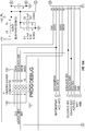
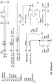
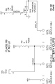
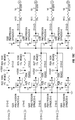
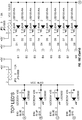
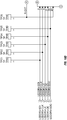
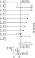
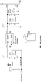
- Figures 10A through 10D are electrical circuit diagrams for this embodiment of the flare10 and Appendix A sets for a component list that corresponds to the electrical diagrams of Figures 10A through 10D .
- the flare 10 of this example comprises a top wall 12, bottom wall 14 and side wall 16.
- the side wall 16 is translucent.
- translucent windows 23a, 23b, 23c and 23d are formed in the top wall 12.
- the entire or substantially all of the top wall 12 may be translucent.
- the bottom wall 14 may be entirely or substantially non-translucent or devoid of any locations where light is directed from or through the bottom wall.
- the flare 10 Defined within the walls of the flare 10 is an interior area which houses a battery, electronic circuitry and a plurality of LEDs. Some of the LEDs (i.e., side-emitting LEDs) are positioned to direct emitted light through the translucent side wall 16 so that light is projected around (e.g., 360 degrees) the flare 10.
- Figure 9 shows an example of how the side-emitting LEDs may be positioned to cast their light through the side wall 16 such that the light will be visible 380 degrees around the flare 10.
- the side-emitting LEDs may be slightly angled upwardly such that the emitted light will rise from the flare 10 when the flare is positioned bottom-side-down on the ground or roadway surface. For example, if the side-emitting LEDs are angled 5 degrees above horizontal, light from the side-emitting LED's will be clearly visible to motorists approaching from a distance of about 120 feet.
- LEDs are positioned to direct light through the translucent windows 23a, 23b, 23c, 23d in the top wall 12 of the flare 10.
- On the top wall 12 of the flare 10 are a control button 18, a power button 20, a small green indicator LED 22a and a small red indicator LED 22b.
- the control button 18 is also referred to herein as the pi ( ⁇ ) button.
- the bottom wall 14 may be fully, substantially or at least partially opaque or non- translucent.
- a portion of the bottom wall 14 comprises a battery compartment cover 30 which is held in place by latches 28. When it is desired to access or change the battery or batteries, the latches 28 may be opened and the battery compartment cover 30 removed.
- four (4) AA cell batteries are positioned inside the device under the battery compartment cover 30.
- Other alternative power sources including solar collectors and/or rechargeable batteries, may be used instead of the standard AA cell batteries of this embodiment.
- the power button 20 is briefly depressed or tapped. Once the power button is pressed a steady green LED 22a on the top wall 12 will illuminate. This indicates that the flare and radio are powering up.
- the first flare 10 will take approximately 4 seconds to turn on. At the end of the 4 seconds the green LED will disappear and, if the flare 10 is positioned horizontally, 12 side-emitting LEDs will emit flashing light directed through the side wall 16. Alternatively, if the flare is positioned vertically, 4 bright top-emitting LEDs will emit flashing light through the top wall windows 23a-23d.
- the operator may briefly depress (e.g., tap) power button 20 of another flare in the group. Similar to the first flare 10, once the power button 20 is pressed a steady green LED will illuminate on the top wall 12 of the second flare 10, indicating that the second flare is powering up. This second flare 10 will take about 1 second to turn on. At the end of the 1 second period the green LED will disappear and the side-emitting LEDs or top-emitting LEDs of the second flare 10 will begin to flash depending on the orientation (i.e., vertical or horizontal) of the second flare 10.
- the 2nd flare 10 will automatically identify itself as the second flare in the sequence and will begin to emit flashes of light in sequence (i.e., a specific time after) flashes emitted from the first flare 10. This set up procedure is then repeated for the remaining flares 10 in the group.
- Each preceding flare 10 must be flashing (and this transmitting its sequence number) before turning on the next flare 10.
- each flare 10 may initially be held above the ground in line-of-site of the preceding flare when turning on, thereby ensuring that the flare 10 will receive the radio signal from the preceding flare without attenuation of the signal due to proximity to the ground.
- All of the flares in the group may be picked up all the flares and placed in a carry case while they are still flashing. This will help to prevent the user from inadvertently leaving inoperative flares on the side of the road.
- the carrying case may be constructed such that the flares flashing inside of the case will cause the case to illuminate thereby enhancing the ability of oncoming vehicle drivers to see and avoid a user who is carrying the case.
- the user may then hold down the power button 20 on any one of the flares 10 in the case, thereby causing all of the flares 10 in the case to power off.
- any communication between flares to pass along flash pattern, top versus side LED choice (for battery saving), on/off, sequence pattern (one flare marching, two flares marching, fast march, slow march, etc.) can be mimicked by a remote control device, Smart Phone app, cellular communication, infra-red controller, etc.
- the operator can turn on and off the entire group of flares, control the operation, direction of flash, battery saving, flash pattern, amongst other features, from a distance away from moving vehicles and in the safety of their vehicle. They need not be close to flare number 1, as any flare in the mesh network or "flock” passes all commands to all flares in the network or "flock". The operator could be close to number 20 of 30 flares and control the entire network.
- the ability to inhibit the LED flashing while maintaining radio communication is a key feature in battery savings. Law enforcement, for example, will set up an alcohol check point using flares to alert and guide approaching vehicles. They typically will set up the DUI check point several hours prior to actual beginning surveillance. If the flares were flashing during this entire period and the 8 hours of the active surveillance battery consumption would be excessive. However, with a remote control unit the operator could set up the flare pattern, test that they are flashing as desired, and then "inhibit" the flashing of the LEDs to save battery.
- the continuing radio communication maintains sequence numbers, patterns, direction of flashing LEDs, etc., and occurs during milliseconds each second and consumes little power. Hours later when the operator wishes to commence inspection of vehicles, she can simply tap a button on the remote control to turn on the flashing LEDs. It is the LEDs that consume the majority of battery capacity and this capability mitigates this cause of battery drain.
- the flare 10 may be equipped with an accelerometer or gravity sensor, as discussed above and the accelerometer or gravity sensor may be operative to sense the current orientation (i.e., horizontal or vertical) of the flare 10 and to cause either the top-emitting or side-emitting LEDs to emit light, depending on which orientation is sensed.
- the current orientation i.e., horizontal or vertical
- the accelerometer or gravity sensor may be operative to sense the current orientation (i.e., horizontal or vertical) of the flare 10 and to cause either the top-emitting or side-emitting LEDs to emit light, depending on which orientation is sensed.
- the flare 10 When the flare 10 is in the horizontal orientation (lying flat on the ground) the 12 side-emitting LEDs will emit flashes of light through the translucent side wall 16.
- the flare 10 is in the vertical orientation (e.g., when magnetically attached to the back of a truck tailgate) the 4 top-emitting LEDs will emit flashes of light through the top wall windows 23a-23d.
- the flare 10 will default to a "dynamic positioning" mode wherein the accelerometer or gravity sensor will cause the flare 10 to automatically switch back and forth between side emitting mode and top emitting mode as the flare 10 undergoes changes between horizontal and vertical orientation.
- the flare 10 is equipped with the above-described locking feature which overrides the default dynamic positioning mode of the flare 10.
- Use of this locking feature allows the flare 10 to be locked in top-emitting mode so that it will continue to emit flashes of light directed through the top wall windows 23a-23d even when the flare 10 is placed in a horizontal orientation.
- the pi ( ⁇ ) button 18 is pressed.
- the green indicator LED 22a will flash once to indicate that the flare is locked in the top emitting mode.
- Pressing the pi ( ⁇ ) button 18 a second time will cause the flare 10 to transition to and become locked in side-emitting mode, wherein the side-emitting LEDs emit light through the side wall 16 and the brighter top-emitting LEDs are turned off.
- the green indicator LED 22a will then flash twice to indicate that the flare 10 is now locked in side-emitting mode.
- Pressing the pi ( ⁇ ) button 18 a third time will disengage the locking feature and restore the flare 10 to its default dynamic LED orientation mode.
- the green indicator LED 22a will flash three times to indicate the flare is now in the default state.
- Patterns Once a plurality of the flares 10 are operating, the user has the option of choosing between 5 flashing patterns. To change patterns, the operator simply taps (does not hold) the power button 20 on one of the flares 10 in the group. This will cause the flare to cycle through a series of available flashing patters, e.g., Pattern 1 (default), Pattern 2, Pattern 3, Pattern 4, Pattern 5, and back to Pattern 1. In this example, the default Pattern 1 is a bright, slow and smooth pattern. Pattern 5 is a fast pattern, Pattern 2 is two flares 10 flashing as a pair and marching down the string of pared flares, and Pattern 3 is two flares flashing separated by a non-flashing flare, thereby spacing the flash out. Pattern 4 is a tail-off flash pattern. Once one of the flares 10 in the group is changed to a non-default flash pattern, all of the remaining flares 10 in the group will then self-synchronize to that selected flash pattern due to the mesh network or flocking protocol used, as described above.
- Pattern 1 default
- the flares 10 can be assigned to specific groups and set to different group frequencies. Flares in each group may bear identifying marks (e.g., yellow, blue, green, beige, or black dots) to indicate different groups. For example, different police units might carry different group numbers so that they do not interfere with each other when deployed in close proximity.
- identifying marks e.g., yellow, blue, green, beige, or black dots
Description
- The present invention relates generally to the fields of electronics and traffic engineering and more particularly to flare devices and methods for marking hazards or intended routes of travel on roadways and the like.
- Flashing orange traffic safety lamps are commonplace along highways and waterways. Passive cones are often used to mark the boundaries or edges of roadways. They are used during road construction, traffic detours, and for emergency to route traffic through unfamiliar redirection. These passive cones are typically used over an entire 24-hour period, which includes darkness and may include poor visibility. Always on, or blinking, lights or reflectors are often used to define the border of a road that has temporarily changed and no longer follows the path that drivers expect or have become use to seeing.
- Traffic is often controlled using large, trailer-like signs with electric generators or photocells that are towed behind a vehicle and left at the detour site. These signs create a large arrow that directs traffic, but the arrow does not guide the driver around a curve or through unfamiliar road courses. Similarly, nautical traffic entering a harbor is guided via buoys and shore- based lights, which when set upon the backdrop of terrestrial lighting, can be confusing. Similarly, emergency or temporary aircraft runways for military, civilian, police, and Coast Guard air equipment, both fixed wing and rotary wing, lack proper sequenced lights that designate direction and location of the runway. This invention provides a system that is both low in cost and easy to implement, one that can be deployed quickly when necessary to aid aviators when landing or taking off on open fields or highways.
- Also, traditional magnesium-flame roadside flares are sometimes used by first responders and workers to alert drivers to the presence of an emergency or maintenance event. There has been movement away from use of flame flares as they result in fire danger, pollution, and toxic fumes. Electronic flares that shine brightly on the roadside have begun to replace these ignited devices. However, frequently during a maintenance or emergency event there are numerous vehicles with roof-top and bumper-level red, orange, blue lamps flashing. This light noise" can introduce confusion to an approaching driver.
- In recent years, electronic roadside flares have been developed as alternatives to magnesium flame flares, reflectors, cones, markers and other previously used flares and marker devices.
WO2014130842 (SELEVAN JAMES R) describes systems and methods for marking a route, path or boundary. Signaling modules are positioned in an array to mark the route, path or boundary. The modules undergo radiofrequency communication with one another and emit signals in sequence from a first-positioned module of the array to a last-positioned module of the array. A selected one or more of the modules is/are programmed or adapted to emit a signal that is distinguishable from the signals emitted by the other modules. - The present invention provides new electronic flare devices and their methods of use.
- In accordance with the present invention, there is provided an electronic light emitting flare as set out in appended
claims 1 to 6, a system as set out in appendedclaims 7 to 13 and related methods of use as set out in appendedclaims - Still further aspects and details of the present invention will be understood upon reading of the detailed description and examples set forth herebelow.
- The following detailed description and examples are provided for the purpose of non-exhaustively describing some, but not necessarily all, examples or embodiments of the invention, and shall not limit the scope of the invention in any way.
-
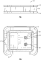
FIG. 1 is a left perspective view of an embodiment of an electronic traffic safety guidance flare; -
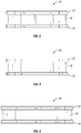
FIG. 2 is a right side view of the embodiment ofFig. 1 ; -
FIG. 3 is a left side view of the embodiment ofFig.1 ; -
FIG. 4 is a front view of the embodiment ofFig. 1 ; -
FIG. 5 is a rear view of the embodiment ofFig. 1 ; -
FIG. 6 is a top view of the embodiment ofFig. 1 ; and -
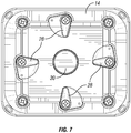
FIG. 7 is a bottom view of the embodiment ofFig.1 . -
Fig. 8 is a diagram illustrating one example of LED orientation in the flare device ofFigures 1 -7 . -
Figures 9A and 9B show steps in a method for using the flare device ofFigures 1-7 for internal lighting of traffic cones. -
Figures 10A through 10D are electrical diagrams of components of the flare device ofFigures 1 through 7 . Accompanying Appendix A lists components shown in the diagrams. - The following detailed description and the accompanying drawings to which it refers are intended to describe some, but not necessarily all, examples or embodiments of the invention. The described embodiments are to be considered in all respects only as illustrative and not restrictive. The contents of this detailed description and the accompanying drawings do not limit the scope of the invention in any way.
- The ability to coordinate the pattern of illumination between electronic roadside flares enhances the approaching driver's perspective. Sequential flashing provides directional information, while simultaneous flashing provides a more dramatic "warning". One method of coordinating flash timing of roadside flares is to connect them via a single wire. However, this method does introduce the entanglement of the wire in the storage container, the potential for workers to trip over the wire, and delayed deployment.
- Wireless coordination of flashing between flares (e.g., causing flares in a row or array to flash in consecutive sequence or other desired pattern) be accomplished using various different modalities, such as radiofrequency transmission, light, or sound waves.
- Using a microcontroller, the flare can analyze sensors to establish a communication link. The media through which the information is transferred can be light, sound, or radio waves. The microcontroller will receive information from a radio receiver, light sensor, or sound sensor. Once the information about number and position of other sensors is received the microcontroller can then establish its position in the sequence and broadcast a message that tells other flares where it is in the string, its relative distance, temperature, elevation, etc.
- For example, some embodiments of flare devices of the present invention may utilize flocking protocols to facilitate the desired inter-flare communication and function. Examples of flocking protocols are described in copending United States Patent Application Serial No.
14/186,582 filed February 21, 2014 - Also, for example, some embodiments of flare devices of the present invention may utilize mesh networks to facilitate the desired inter-flare communication and function. Examples of such mesh networks are described in United States Patent No.
8,154,424 issued April 10, 2012 as well as United States Patent Application PublicationsUS2013/0293398 published November 17, 2013 andUS2013/0271294 published October 17, 2013 . - Light Transmission-- Using light as an information transmission media - Light emitted from one flare can represent a message that is received by another flare. This message could be as simple as a "trigger" event to tell the second flare to turn on, or it could be more complex. In the simplest form, presence of light from one flare would trigger an event in another flare. This second flare might delay, for example, 100 milliseconds and then flash. In the ideal setting this could represent a simple method of providing a sequential pattern of flashes. However, it is possible that
flare number 4, for example, would receive light fromflare number 1 and flash at an inappropriate interval. Thus, the sequential flashing of flares cannot rely upon the simple trigger of a preceding flare. Using the flash of a flare, the message to other flares can be "embedded" within the light signal in a Pulse Width Modulated" scheme. Hence, what appears as a 40 or 100 millisecond (as an example) steady flash of light to the human observer can actually represent a 2, 4, 8, 16, 32, 64 bit or greater word length containing information that would provide coordinating information. The LED and associated drive electronics (microcontroller, transistors, etc.) can respond to signals and voltages that are nanoseconds in length. An 80 millisecond flash of light (appearing as a single flash to the human observer) can actually be made up of a series of thousands of rapid flashes "modulated" on and off so quickly that the human eye cannot discern the pulsed nature of the flash. For example, when the first flare is turned on it could "look" or "listen" for light that contains an identifying message (a digital word representing a "hello, I am a flare flashing". In the absence of seeing such a pattern it would start flashing with a modulated message to the effect, 'I amflare number 1 ". When the second flare is turned on it will "look" for light speaking its same language., It would see light coming fromflare 1 defining its sequence number (1).Flare 2 would then turn on and begin flashing with a modulated pattern defining its sequence number and so on. - The transmission of light is inherent in the flash of the flare. Hence, the orange or red or blue or other color LED flashing to alert drivers is also the light source to send the message. On each flare there will be a number of light sensors - photodiodes, photo-resistors, phototransistors, etc. These sensing devices will respond to the presence of any light in their frequencies (sensitivity) range. The photodetector could be chosen or "tuned" to respond to only one color. However, the presence of the digital word modulated in the warning flash eliminates the need to narrow the sensitivity spectrum of light. Any light sensed by the photo-detector will represent "noise", but only light modulated with the appropriate digital code will result in the microcontroller responding correctly.
- To reduce cost, the physics of the Light Emitting Diode that emits the light (flash) could be used to an advantage by also being used as a light sensor. During the period when the LED is not flashing the voltage on the LED could be reversed. During this period when the voltage is reversed the LED can be used as a light sensor to pick up transmitted light from other flares. This would eliminate or mitigate the need for additional photo-detectors. Furthermore, as there are often 12 or more LEDs on roadside electronic flares, each of these could be used as a photo-detector thereby 'looking" in a 380 degree circle. Thus, the orientation of the flare on the roadway is irrelevant; the operator can toss the flares onto the roadway without regard for whether it is pointed in a particular direction to pick up the light beam from an adjacent flare.
- Alternatively, light of a specific frequency or spectrum could be used to transmit information. For example, light in the infra-red or ultra-violet frequency range could be used. Photo-detectors sensitive to only these frequencies would filter out "noise" present on the roadway at night. Sunlight (white light) would contain energy in all spectrums, and thus the information content (Pulse Width Modulation) would ensure that light noise does not interfere with the intelligent transfer of information.
- Light intensity in addition to color and modulation adds additional information to the microcontroller. As the intensity of light diminishes in a known and predictable way with distance, the "brightness" or intensity of light emanating from a flare can aid in determining sequence. In the simple case of using the flash of a flare as a triggering action, the relative intensity of the received light could "disambiguate" light emitted from two or more flares. If the lights are physically placed in a linear "string" or path and flare
number 5 senses light fromflare number 4 andnumber 3, it could identify which is which by measuring the intensity of the light received. It would then be able to identify number 3 (weaker flash therefore farther away) andnumber 4. - Radio Transmission - Light represents an inexpensive means of transmitting information between flares. However, there are limitations associated with light energy. The transmission of light is inefficient when compared to radio transmission. Light can be blocked by opaque objects that might find their way between the flares (cars, people, cones, etc.). The range of transmission is limited due to energy requirements. Radio transmission provides a solution to these limitations. Using radio waves a flare could send digital or analog signals to other flares that identify its sequence in the pattern much in the same way as light could be used.
- Sound transmission - Ultrasonic or other frequency sound can be used as a transmission media. Modulated sound waves could carry information defining flare number and location relative to other flares. In addition, sound waves diminish in strength in a relative and predictable way, the strength of the sound "heard" from two different flares at different distances would aid the microcontroller firmware in establishing which is farther away and what the sequence number is. In addition, once the sound is sensed by appropriate transducers and electronics the frequency could be filtered to eliminate noise produced by vehicles on the roadway.
- 4) Irrespective of the transmission media, the flares can be networked using a "mesh" network where information is transmitted between flares, up and down a group, without need for a master flare or slave flare, and where all communication is internal to the group of flares. No external signal is required, but could be used to remotely control the group of flares. If one flare is turned on and it is in "range" of communication with only one flare, this second flare would then send the "state" to any other flares within range. Similarly, the remote control unit needs to be in range of only one flare for the command to be distributed to all of the flares.
- To be practical roadside flares must be small and lightweight. An individual might deploy 10 flares on the roadside and stowing 10 objects in a vehicle requires small size. Small size and light weight define limits on the battery size and available energy. Hence, methods to reduce energy consumption are key factors in designing a roadside flare. One method is to turn off (not illuminate) LEDs oriented in a direction not seen by on-coming vehicles. All existing roadside flare designs power all LEDs with each flash. An approach that would reduce significantly the energy required and prolong battery life is to sense the direction of traffic flow. This can be done using light from on-coming headlights, sound intensity, sound frequency (Doppler Effect of a passing vehicle), thermal detection of engine heat, radar, ultrasound, sonar, and air pressure. When the direction of traffic is detected, the microcontroller will turn off LEDs that would illuminate the "back" side of the flare.
- In a similar fashion, the flares can be mounted in a vertical position (as opposed to horizontal on the road surface). This vertical orientation might be used when magnetically attaching the flare to the tail-gate panel of a truck or the side of a vehicle. As the flare is designed for light output in the horizontal plane (on the road surface), when placed vertically much of the light energy would be directed towards the sky, ground, and left and right. Accordingly, a sensor could detect the "tilt" using an accelerometer, gyroscope, MEMS device, mechanical ball tilt sensor, thermal tilt sensor, light detecting tilt sensor, etc. and send this information regarding orientation angle to the microcontroller. The microcontroller, "aware" of the angle of tilt, would choose which LEDs to illuminate (for example, the side LEDs when horizontal and "top" LEDs when mounted vertically on its side or magnetically attached to the tail gate of a vehicle). This dynamic choice of LED to illuminate based upon angle of tilt maximizes light output in the direction of approaching traffic and minimizes unnecessary battery consumption associated with lighting LEDs not visible to oncoming traffic. When placed in the vertical plane the side lights could be turned off and LEDs located in the top of the flare directed towards on-coming traffic could be turned on.
- Motion-Actuated or Percussion-Actuated On/Off Feature: In some instances, such as during nighttime operation in areas which are not well lit, it may be difficult to see standard buttons on the surface of an enclosure. Rather than using a discrete on/off switch such as a capacitance button or other specifically-located actuator to cause the flare to begin emitting light (i.e., "turn on") or cease emitting light (i.e., "turn off'), the flares of the present invention may optionally be equipped with an on/off switch which is activated by a motion or percussion sensor, such as an accelerometer, tilt sensor, gyroscope or MEMS (micro electrical mechanical system) set to detect a particular movement of, or percussion (e.g., tapping) on the flare. For example, the electronic circuitry of the flare may be adapted so that rapid partial rotation of the flare in a first (e.g., clockwise) direction causes the flare to turn on and subsequent rapid partial rotation of the flare in the opposite (e.g., counterclockwise) direction causes the flare to turn off. Alternatively, on and off might be triggered by turning the flare upside down, or via some other motion or percussion. As a further example, percussing (e.g., tapping or rapping) the flare with the palm of the operator's hand could be used as a trigger to turn the flare off or on, with the sensor "tuned" to exclude normal vibration to be expected during transport and storage. For example, the circuitry may be adapted to recognize a specific number of consecutive percussions (e.g., three consecutive taps or raps) as the signal to cause the flare to initially turn on or subsequently turn of. Alternatively or additionally, to avoid unintended turn on of the flare, which could result in rapid unintentional depletion of the battery, a 3-axis accelerometer may be used to detect acceleration in the X, Y, and Z axis. For example, simply turning the flare over three times within a defined period (e.g., 3 seconds) would result in the Z-axis experiencing a swing from +9.8 meters per second per second (+1G) to -1G. The microcontroller would receive this information from the accelerometer via an interrupt signal. This preprogrammed "gesture", stored in the accelerometer, would generate an interrupt from the accelerometer, and this interrupt would "wake" the microcontroller from a low-power "sleep" mode. Hence, the microcontroller can be in a low-power state (sleep) while the device is off. The accelerometer has sufficient intelligence to recognize the preprogrammed gesture and wake the microcontroller from its low power mode. The preprogrammed gesture must utilize the X, Y, and Z axis to insure proper turn-on but avoid false startup. When horizontal, the X and Y axis experience 0 (zero) acceleration. Only the Z axis is experiencing +1G. However, if the surface is bumped up and down the accelerometer would experience acceleration on the Z-axis only and this could mimic turning the flare over to the other side. Thus, the flare would turn on if three bumps of sufficient magnitude occurred within the allotted time period.
- To avoid this false trigger, X- and Y-axis information is introduced. A simple bounce of the horizontally-oriented flare in the trunk of the car would be interpreted as turning over of the flare (Z-axis would transition from +1G to -1G). If X- and Y-axis changes were expected as well, then vertical displacement alone would not falsely turn on the flare. For the Z-axis to experience +1G to -1G, X- or Y-axis must transition from 0G to +1G (or -1G) to 0G. Introducing the Boolean - (Z-transition AND ((X-transition from 0G to +/-1G to 0G) OR (Y-transition from 0G to +/-1G to OG))) eliminates "bumps" alone as a triggering event.
- Group On/Off Feature: Some embodiments of the invention may be equipped with a group on/off feature whereby turning off any one of the flares would turn off all of the flares in the group. Using radio, sound, light, etc., to transmit information between flares one could send a message from any one flare to the remainder of flares within proximity. This message could be used to turn off all of the flares by simply turning off any single flare.
- The ability to turn all of the flares off by turning off a signal flare allows the operator to retrieve the flares from the roadside while they are still flashing. This would reduce the likelihood that a flare would be inadvertently left behind on the dark roadway. In addition, when placed into a transparent or translucent case or satchel the flashing group of flares would represent a warning beacon to oncoming traffic that the operator is on the side of the road. When all of the flares have been retrieved, the operator could enter the safety of their vehicle or exit the roadway and turn off any one flare. The entire group of flares would extinguish. The operator does not have to turn off all of the flares individually.
- Elevation of the LED above the road surface may vary as a function of position in the string. To aid in providing direction and visibility, the height of the LEDs providing illumination could vary. For example, in a 10 flare string flashing in sequence, the height above the road surface of
number 1 could be 3 inches, with each flare progressing in height by 6 inches. As a result, the last flare in the string might be 5 feet above the road surface (on a flexible stalk). This would add additional perspective for a driver from a distance, offering linear as well as elevation cues to the hazard ahead. - Locking Feature: With LEDs aimed in specific directions, including vertically towards the sky, the flare is designed to purposely illuminate the inside of a container, barrel, cone, or delineator. When placed on the road surface under a traffic cone, barrel, delineator, etc., light emanating from the flare in the vertical direction efficiently illuminates the container. However, light aimed vertically when the flare is on the road surface and not placed under a container leads to inefficiency of energy use as this light is directed skyward. Dynamic switching of side versus top (vertical) LEDs is accomplished using a tilt sensor (accelerometer) and the information the sensor provides to the microcontroller. It is necessary, when placed under a container, to override the tilt sensor. The user must be able to "lock" the choice of LEDs (top or side) for a particular deployment. This effectively disables dynamic, tilt-sensing microcontroller control of the LED choice.
- The "locking" feature can be activated by pressing two buttons simultaneously, or by pressing and holding one button for a prolonged switch closure (2 seconds or more, for example). Alternatively, a single tap of a button could lock the orientation of LED illumination, or step through choices such as a single press turns on the side LEDs, a second press turns on the top LEDs, a third press turns on both side and top LEDs, and the cycle repeats itself with additional presses of the button.
- Motion Actuated LED Switching, dynamic switching of LED orientation using a tilt sensor or accelerometer, locking of LED orientation using various user interface button presses, all can be implemented in either a standalone flare or one communicating with its neighbors.
- All of the features described thus far, save for the "group off" capability, can be incorporated in either: a "smart flare" that incorporates mesh or flocking technology (radio frequency, light transmission, infrared transmission, sound, transmission, etc.) for flare-to-flare communications or in a "dumb" flare used individually or in a group wherein the flares do not communicate with each to synchronize their flashing, but rather flash randomly in non- synchronized fashion.
-
Figures 1 through 7 show one a non-limiting example of aflare 10 of the present invention.Figures 10A through 10D are electrical circuit diagrams for this embodiment of the flare10 and Appendix A sets for a component list that corresponds to the electrical diagrams ofFigures 10A through 10D . having a generally rectangular configuration with rounded corners. This example is non-limiting and other alternative configurations or shapes may be used. Theflare 10 of this example comprises atop wall 12,bottom wall 14 andside wall 16. Theside wall 16 is translucent. Also, translucent windows 23a, 23b, 23c and 23d are formed in thetop wall 12. In some embodiments, the entire or substantially all of thetop wall 12 may be translucent. Also, in some embodiments thebottom wall 14 may be entirely or substantially non-translucent or devoid of any locations where light is directed from or through the bottom wall. - Defined within the walls of the
flare 10 is an interior area which houses a battery, electronic circuitry and a plurality of LEDs. Some of the LEDs (i.e., side-emitting LEDs) are positioned to direct emitted light through thetranslucent side wall 16 so that light is projected around (e.g., 360 degrees) theflare 10.Figure 9 shows an example of how the side-emitting LEDs may be positioned to cast their light through theside wall 16 such that the light will be visible 380 degrees around theflare 10. Also, in some embodiments, the side-emitting LEDs may be slightly angled upwardly such that the emitted light will rise from theflare 10 when the flare is positioned bottom-side-down on the ground or roadway surface. For example, if the side-emitting LEDs are angled 5 degrees above horizontal, light from the side-emitting LED's will be clearly visible to motorists approaching from a distance of about 120 feet., - Other LEDs (i.e., top-emitting LEDs) are positioned to direct light through the translucent windows 23a, 23b, 23c, 23d in the
top wall 12 of theflare 10. On thetop wall 12 of theflare 10 are acontrol button 18, apower button 20, a smallgreen indicator LED 22a and a smallred indicator LED 22b. Thecontrol button 18 is also referred to herein as the pi (π) button. Thebottom wall 14 may be fully, substantially or at least partially opaque or non- translucent. A portion of thebottom wall 14 comprises abattery compartment cover 30 which is held in place by latches 28. When it is desired to access or change the battery or batteries, thelatches 28 may be opened and thebattery compartment cover 30 removed. In the embodiment show, four (4) AA cell batteries are positioned inside the device under thebattery compartment cover 30. Other alternative power sources, including solar collectors and/or rechargeable batteries, may be used instead of the standard AA cell batteries of this embodiment. - The following paragraphs describe possible methods of use of a plurality of these
flares 10 in a group (e.g., a row or array). - Turning on the First Flare: To turn on the
first flare 10 of the group, thepower button 20 is briefly depressed or tapped. Once the power button is pressed a steadygreen LED 22a on thetop wall 12 will illuminate. This indicates that the flare and radio are powering up. Thefirst flare 10 will take approximately 4 seconds to turn on. At the end of the 4 seconds the green LED will disappear and, if theflare 10 is positioned horizontally, 12 side-emitting LEDs will emit flashing light directed through theside wall 16. Alternatively, if the flare is positioned vertically, 4 bright top-emitting LEDs will emit flashing light through the top wall windows 23a-23d. - Turning on additional flares: Once the
first flare 10 is on and flashing, the operator may briefly depress (e.g., tap)power button 20 of another flare in the group. Similar to thefirst flare 10, once thepower button 20 is pressed a steady green LED will illuminate on thetop wall 12 of thesecond flare 10, indicating that the second flare is powering up. Thissecond flare 10 will take about 1 second to turn on. At the end of the 1 second period the green LED will disappear and the side-emitting LEDs or top-emitting LEDs of thesecond flare 10 will begin to flash depending on the orientation (i.e., vertical or horizontal) of thesecond flare 10. Because theflares 10 have self-sequencing capability such as the above-described mesh network or flocking protocol, the2nd flare 10 will automatically identify itself as the second flare in the sequence and will begin to emit flashes of light in sequence (i.e., a specific time after) flashes emitted from thefirst flare 10. This set up procedure is then repeated for the remainingflares 10 in the group. Each precedingflare 10 must be flashing (and this transmitting its sequence number) before turning on thenext flare 10. For maximum range, eachflare 10 may initially be held above the ground in line-of-site of the preceding flare when turning on, thereby ensuring that theflare 10 will receive the radio signal from the preceding flare without attenuation of the signal due to proximity to the ground. - Turning Off Flares: There are 2 ways of powering down the flares. 1) Single Flare Off - You can turn off a single flare by pressing and holding (2 seconds) the square pi (ττ) button. A red LED will flash twice indicating it has turned off; 2) Group Off - You can turn off the entire string of flares by simply holding down the Power button for 2 seconds. The red indicator LED flashes while the off command is being sent up and down the string. You must wait until the red LED stops flashing before turning a flare back on.
- All of the flares in the group may be picked up all the flares and placed in a carry case while they are still flashing. This will help to prevent the user from inadvertently leaving inoperative flares on the side of the road. In addition, the carrying case may be constructed such that the flares flashing inside of the case will cause the case to illuminate thereby enhancing the ability of oncoming vehicle drivers to see and avoid a user who is carrying the case. When the user is safely in the user's vehicle or otherwise away from vehicular traffic, the user may then hold down the
power button 20 on any one of theflares 10 in the case, thereby causing all of theflares 10 in the case to power off. - Remote Control of Flare Behavior: By virtue of the communication and network features of the flare, any communication between flares to pass along flash pattern, top versus side LED choice (for battery saving), on/off, sequence pattern (one flare marching, two flares marching, fast march, slow march, etc.) can be mimicked by a remote control device, Smart Phone app, cellular communication, infra-red controller, etc. Accordingly, the operator can turn on and off the entire group of flares, control the operation, direction of flash, battery saving, flash pattern, amongst other features, from a distance away from moving vehicles and in the safety of their vehicle. They need not be close to flare
number 1, as any flare in the mesh network or "flock" passes all commands to all flares in the network or "flock". The operator could be close tonumber 20 of 30 flares and control the entire network. - The ability to inhibit the LED flashing while maintaining radio communication is a key feature in battery savings. Law enforcement, for example, will set up an alcohol check point using flares to alert and guide approaching vehicles. They typically will set up the DUI check point several hours prior to actual beginning surveillance. If the flares were flashing during this entire period and the 8 hours of the active surveillance battery consumption would be excessive. However, with a remote control unit the operator could set up the flare pattern, test that they are flashing as desired, and then "inhibit" the flashing of the LEDs to save battery. The continuing radio communication maintains sequence numbers, patterns, direction of flashing LEDs, etc., and occurs during milliseconds each second and consumes little power. Hours later when the operator wishes to commence inspection of vehicles, she can simply tap a button on the remote control to turn on the flashing LEDs. It is the LEDs that consume the majority of battery capacity and this capability mitigates this cause of battery drain.
- Battery Status Check: Pressing the
pi button 18 while theflare 10 is off will effectuate a battery check. The green or red LED on thetop wall 12 will flash the current battery status, as follows: 5 green flashes = full batteries, 4 green flashes = full batteries, 3 green flashes = good batteries, 2 red flashes = low batteries, 1 red flash = very low batteries. Preferably, in this embodiment, the batteries are replaced between the 3 green flashes and 2 red flashes. - Dynamic LED Orientation: In some embodiments, the
flare 10 may be equipped with an accelerometer or gravity sensor, as discussed above and the accelerometer or gravity sensor may be operative to sense the current orientation (i.e., horizontal or vertical) of theflare 10 and to cause either the top-emitting or side-emitting LEDs to emit light, depending on which orientation is sensed. When theflare 10 is in the horizontal orientation (lying flat on the ground) the 12 side-emitting LEDs will emit flashes of light through thetranslucent side wall 16. When theflare 10 is in the vertical orientation (e.g., when magnetically attached to the back of a truck tailgate) the 4 top-emitting LEDs will emit flashes of light through the top wall windows 23a-23d. Unless the locking feature is engaged, theflare 10 will default to a "dynamic positioning" mode wherein the accelerometer or gravity sensor will cause theflare 10 to automatically switch back and forth between side emitting mode and top emitting mode as theflare 10 undergoes changes between horizontal and vertical orientation. - Locking Feature/Override of Dynamic LED Orientation: In this example, the
flare 10 is equipped with the above-described locking feature which overrides the default dynamic positioning mode of theflare 10. Use of this locking feature allows theflare 10 to be locked in top-emitting mode so that it will continue to emit flashes of light directed through the top wall windows 23a-23d even when theflare 10 is placed in a horizontal orientation. To trigger this locking feature, after theflare 10 has been powered up and is flashing in either the horizontal or vertical mode, the pi (π)button 18 is pressed. Pressing thepi button 18 one time while theflare 10 is operating overrides the dynamic LED orientation and causes theflare 10 to be locked in top-emitting mode with the bright top-emitting LEDs emit flashes of light through the translucent windows 23a-23d in thetop wall 12 of theflare 10 and the side emitting LED off. Thegreen indicator LED 22a will flash once to indicate that the flare is locked in the top emitting mode. Pressing the pi (π) button 18 a second time will cause theflare 10 to transition to and become locked in side-emitting mode, wherein the side-emitting LEDs emit light through theside wall 16 and the brighter top-emitting LEDs are turned off. Thegreen indicator LED 22a will then flash twice to indicate that theflare 10 is now locked in side-emitting mode. Pressing the pi (π) button 18 a third time will disengage the locking feature and restore theflare 10 to its default dynamic LED orientation mode. Thegreen indicator LED 22a will flash three times to indicate the flare is now in the default state. - Patterns: Once a plurality of the
flares 10 are operating, the user has the option of choosing between 5 flashing patterns. To change patterns, the operator simply taps (does not hold) thepower button 20 on one of theflares 10 in the group. This will cause the flare to cycle through a series of available flashing patters, e.g., Pattern 1 (default),Pattern 2,Pattern 3,Pattern 4,Pattern 5, and back toPattern 1. In this example, thedefault Pattern 1 is a bright, slow and smooth pattern.Pattern 5 is a fast pattern,Pattern 2 is twoflares 10 flashing as a pair and marching down the string of pared flares, andPattern 3 is two flares flashing separated by a non-flashing flare, thereby spacing the flash out.Pattern 4 is a tail-off flash pattern. Once one of theflares 10 in the group is changed to a non-default flash pattern, all of the remainingflares 10 in the group will then self-synchronize to that selected flash pattern due to the mesh network or flocking protocol used, as described above. - Changing Batteries: In this example, no tools are required to open the battery compartment to change the batteries. The battery cover latches 28 may be manually moved to their open positions and the
battery cover 30 may then be removed to access the battery compartment. - Multiple Groups: Should the operator wish to use several strings or groups of
flares 10 in close proximity, theflares 10 can be assigned to specific groups and set to different group frequencies. Flares in each group may bear identifying marks (e.g., yellow, blue, green, beige, or black dots) to indicate different groups. For example, different police units might carry different group numbers so that they do not interfere with each other when deployed in close proximity. - It is to be appreciated that, although the invention has been described hereabove with reference to certain examples or embodiments of the invention, various additions, deletions, alterations and modifications may be made to those described examples and embodiments without departing from the intended scope of the invention. For example, any elements, steps, members, components, compositions, reactants, parts or portions of one embodiment or example may be incorporated into or used with another embodiment or example, unless otherwise specified or unless doing so would render that embodiment or example unsuitable for its intended use. Also, where the steps of a method or process have been described or listed in a particular order, the order of such steps may be changed unless otherwise specified or unless doing so would render the method or process unsuitable for its intended purpose. Additionally, the elements, steps, members, components, compositions, reactants, parts or portions of any invention or example described herein may optionally exist or be utilized in the absence or substantial absence of any other element, step, member, component, composition, reactant, part or portion unless otherwise noted. All reasonable additions, deletions, modifications and alterations are to be considered equivalents of the described examples and embodiments and are to be included within the scope of the following claims.
Claims (15)
- An electronic light emitting flare (10) comprising:a housing comprising a top wall (12), bottom wall (14) and at least one side wall, (16) wherein at least a portion of the side wall (16) is translucent and at least a portion of the top wall (12) is translucent;a plurality of light emitters positioned within the housing;electronic circuitry; anda power source;characterized in that:the electronic circuitry is connected to the power source and light emitters to drive at least some of the light emitters to emit flashes of light directed through said at least one translucent portion of the housing side wall and alternately drive at least some of the light emitters to emit flashes of light directed through said translucent portion of the top wall; andthe electronic light emitting flare further comprises a switching circuitry configured to switch back and forth between a) a side emitting mode wherein light emitters emit flashes of light directed through said at least one translucent portion of the side wall and b) a top emitting mode wherein light emitters emit flashes of light directed through said at least one translucent portion of the top wall.
- An electronic light emitting flare according to claim 1 wherein the electronic circuitry is adapted to perform at least one function selected from:causing the flare to synchronize the timing of its emission of light with that of neighboring flares in a group or array of said flares;employing a mesh network or flocking protocol to synchronize its emission of light with that of neighboring flares in a group or array of said flares;sense motion or percussion and cause the flare to turn on or off in response to the sensing of motion or percussion;communicate with other flares in a group or array such that turning on or off of one flare in the group or array causes likewise turning on or off of other flares in the group or array.
- An electronic light emitting flare according to claim 1 further comprising a motion or percussion sensor selected from motion sensors, percussion sensors, accelerometers, tilt sensors, gyroscopes and micro electrical mechanical systems, and wherein the electronic circuitry causes the light emitters to turn on and/or off in response to the sensing of motion or percussion by the motion or percussion sensor.
- An electronic light emitting flare according to claim 1 wherein the switching circuitry comprises at least one apparatus or functionality selected from:a motion activated switching apparatus which causes switching between the side emitting mode and the top emitting mode in response to certain movements of the flare;a motion activated switching apparatus which causes dynamic light emitters orientation such that the flare switches back and forth between the first and second modes as the flare is moved back and forth between a horizontal orientation and a vertical orientation; anda locking function which allows a user to lock the flare so that it will operate in either a first mode or a second mode irrespective of whether the flare is in a horizontal or vertical orientation;a locking function that locks the flare in a second mode of operation such that flashes of light are directed through translucent portions of the top wall while the flare is positioned in a substantially horizontal orientation on the ground or on a road surface.
- An electronic light emitting flare according to claim 4 further comprising one or more magnets for magnetically attaching the flare to a ferromagnetic member.
- An electronic light emitting flare according to claim 1 wherein the electronic circuitry is adapted to receive control signals from a remote control devices in addition to communication from neighboring flares.
- A system comprising an electronic light emitting flare according to claim 4 in combination with a traffic cone or other traffic marking or channelizing device that is positionable on the ground or road surface over top of the flare such that flashes of light emitted out of said at least one translucent portion of the top wall of the flare will illuminate the cone or other traffic marking or channelizing device.
- A system according to claim 7, the electronic light emitting flare further comprising an on/off button and a utility button, the on/off button being useable to turn the flare on and off and the utility button being useable to trigger the flare to perform certain function.
- A system according claim 7 operable in a mode wherein, when the flare if positioned on a horizontal surface, light is cast through the side wall of the flare and said light is directed approximately 5 degrees upward from horizontal.
- A system comprising a plurality of electronic light emitting flares according to claim 1 wherein the flares communicate such that when an on/off switch of one of the flares is turned on, all of the other flares will also turn on and wherein the flares communicate such that when an on/off switch of one of the flares is turned off, all of the other flares will also turn off
- A system according to claim 10 further comprising a carrying case which is at least partially translucent such that placement of the flares within the carrying case while the flares are turned on will cause light to be emitted from the carrying case.
- A system comprising a plurality of electronic light emitting flares according to claim 2 wherein the electronic circuitry is adapted allow a user to choose a selected flash pattern from a plurality of available flash patterns and once a user has chosen a selected flash pattern on one of said plurality of flares, to cause the others of said plurality of flares to then self-synchronize to that selected flash pattern.
- A system comprising a plurality of electronic light emitting flares according to claim 6 in combination with a remote control device selected from: a smart phone, cellular communication, infra-red controller, dedicated unit or computer.
- A method of signaling using an electronic light emitting flare or system according to any preceding claim, said method comprising the steps of:placing said one or more flares at one or more desired locations;powering on said one or more flares;causing the electronic circuity of said one or more flares to drive emission of flashes of light from the light emitters for a desired period of time;switching back and forth between said side emitting mode and said top emitting mode;after completion of the desired period of time, removing said one or more flares from the desired locations; andpowering down said one or more flares.
- A method according to claim 14 wherein:each of said one or more flares includes a motion activated switching apparatus which causes switching between the side emitting mode and the top emitting mode in response to certain movements of the flare; andthe step of selecting either said side emitting mode or said top emitting mode is accomplished in response to said certain movements of said one or more flares.
Applications Claiming Priority (2)
| Application Number | Priority Date | Filing Date | Title |
|---|---|---|---|
| US201462080294P | 2014-11-15 | 2014-11-15 | |
| PCT/US2015/060770 WO2016077812A1 (en) | 2014-11-15 | 2015-11-15 | Sequential and coordinated flashing of electronic roadside flares with active energy conservation |
Publications (3)
| Publication Number | Publication Date |
|---|---|
| EP3218887A1 EP3218887A1 (en) | 2017-09-20 |
| EP3218887A4 EP3218887A4 (en) | 2018-07-18 |
| EP3218887B1 true EP3218887B1 (en) | 2020-10-14 |
Family
ID=55955183
Family Applications (1)
| Application Number | Title | Priority Date | Filing Date |
|---|---|---|---|
| EP15858697.4A Active EP3218887B1 (en) | 2014-11-15 | 2015-11-15 | Sequential and coordinated flashing of electronic roadside flares with active energy conservation |
Country Status (4)
| Country | Link |
|---|---|
| US (2) | US9835319B2 (en) |
| EP (1) | EP3218887B1 (en) |
| JP (3) | JP6776251B2 (en) |
| WO (1) | WO2016077812A1 (en) |
Families Citing this family (18)
| Publication number | Priority date | Publication date | Assignee | Title |
|---|---|---|---|---|
| US20130293396A1 (en) | 2008-03-15 | 2013-11-07 | James R. Selevan | Sequenced guiding systems for vehicles and pedestrians |
| US11313546B2 (en) | 2014-11-15 | 2022-04-26 | James R. Selevan | Sequential and coordinated flashing of electronic roadside flares with active energy conservation |
| US9835319B2 (en) * | 2014-11-15 | 2017-12-05 | James R. Selevan | Sequential and coordinated flashing of electronic roadside flares with active energy conservation |
| US10124757B1 (en) * | 2015-07-23 | 2018-11-13 | Traffic Safety Specialists Inc. | Vehicle collision avoidance system |
| US9630554B1 (en) * | 2016-01-11 | 2017-04-25 | Tychicus E. Whitfield | Labor light system |
| USD854438S1 (en) * | 2017-02-10 | 2019-07-23 | Pi Variables, Inc. | Portable electronic flare |
| US10551014B2 (en) | 2017-02-10 | 2020-02-04 | James R. Selevan | Portable electronic flare carrying case and system |
| CN110770082A (en) | 2017-02-10 | 2020-02-07 | 詹姆斯·R·塞勒凡 | Portable electronic flash carrying case and system |
| USD854437S1 (en) * | 2017-02-10 | 2019-07-23 | Pi Variables, Inc. | Portable electronic flare system |
| US11725785B2 (en) | 2017-02-10 | 2023-08-15 | James R. Selevan | Portable electronic flare carrying case and system |
| USD848890S1 (en) * | 2017-06-13 | 2019-05-21 | Maschinenfabrik Reinhausen Gmbh | Dial for a measuring instrument |
| AU2018297199B2 (en) | 2017-07-06 | 2023-12-07 | Adam Jordan Selevan | Devices and methods for synchronized signaling of the positions of moving pedestrians or vehicles |
| US11739928B2 (en) | 2017-08-10 | 2023-08-29 | Archangel Device Llc | Safety light |
| GB201716442D0 (en) | 2017-10-06 | 2017-11-22 | Highway Resource Solutions Ltd | Governing the operation of an asset within a geo-zone |
| US11035529B2 (en) | 2019-01-29 | 2021-06-15 | Northern Optotronics Inc. | Electronic twist flare |
| KR102004299B1 (en) * | 2019-06-12 | 2019-07-26 | 박상준 | Notification device for prevention of second accident |
| CN112738962B (en) * | 2019-10-28 | 2024-04-05 | 松下知识产权经营株式会社 | Lighting system |
| CN114929967A (en) * | 2020-01-11 | 2022-08-19 | 亚当·乔丹·塞勒凡 | Apparatus and method for grooming vehicle traffic and enhancing workspace security |
Family Cites Families (64)
| Publication number | Priority date | Publication date | Assignee | Title |
|---|---|---|---|---|
| US3500378A (en) | 1965-06-21 | 1970-03-10 | Thomas E Pickering | Battery-operated barrier light having resilient cushion mounting structure |
| US3787867A (en) | 1971-04-12 | 1974-01-22 | Automatic Power Division Pennw | Navigational aid system |
| US4132983A (en) | 1976-01-12 | 1979-01-02 | Royal Industries, Inc. | Radio synchronized warning light system |
| US4345305A (en) | 1980-08-11 | 1982-08-17 | Flik, Inc. | Portable electronic safety flare system |
| DE3523062A1 (en) | 1984-06-27 | 1986-01-09 | Kyocera Corp., Kyoto | SELF-LUMINOUS LIGHT SIGNALER AND USE OF THE SAME IN A LIGHT SIGNAL ARRANGEMENT |
| US4827245A (en) | 1988-02-23 | 1989-05-02 | Falcor Group Inc. | Portable strobe light system |
| SE500233C2 (en) | 1989-06-16 | 1994-05-09 | Swedish Airport Technology Han | Luminaire for submerged banlight |
| US5294924A (en) * | 1992-01-23 | 1994-03-15 | Cads Electronic Systems, Inc. | Flashing warning light for a traffic control device |
| US5754124A (en) * | 1996-11-13 | 1998-05-19 | Pittco, Inc. | Electrical hazard warning system |
| JP2887130B1 (en) * | 1998-03-10 | 1999-04-26 | 東海旅客鉄道株式会社 | Portable signaling lights for railway maintenance |
| US6705745B1 (en) * | 1999-06-08 | 2004-03-16 | 911Ep, Inc. | Rotational led reflector |
| WO2001081166A1 (en) | 2000-04-20 | 2001-11-01 | Chris Antico | Remote synchronisation |
| US6486797B1 (en) * | 2001-01-05 | 2002-11-26 | Lighting And Electronic Design | Turbo flare hazard maker |
| US20020154787A1 (en) | 2001-02-20 | 2002-10-24 | Rice Richard F. | Acoustical to optical converter for providing pleasing visual displays |
| CA2343435C (en) | 2001-04-06 | 2006-12-05 | International Road Dynamics Inc. | Dynamic work zone safety system |
| US6499858B2 (en) * | 2001-04-27 | 2002-12-31 | David Alan Hart | Illumination device for safety markers |
| US6549121B2 (en) * | 2001-07-31 | 2003-04-15 | Philip Francis Povey | Illuminated emergency signaling device |
| JP4518793B2 (en) * | 2001-09-17 | 2010-08-04 | フィリップス ソリッド−ステート ライティング ソリューションズ インコーポレイテッド | Products based on light-emitting diodes |
| WO2003034369A2 (en) | 2001-10-19 | 2003-04-24 | Hutchins J Marc | Informational system using lighted message arrays for providing direction and guidance to traffic ways |
| US20030164666A1 (en) | 2002-03-01 | 2003-09-04 | Crunk Paul D. | Lamp reflect-reflector/reflect-reflector baffle |
| US10180244B2 (en) * | 2002-04-25 | 2019-01-15 | Haralambos A. Stamatatos | Illuminating safety and notification device |
| US6963275B2 (en) * | 2002-05-31 | 2005-11-08 | Nu-Tech Innovative Products, Llc | Portable warning light apparatus |
| US20040056779A1 (en) | 2002-07-01 | 2004-03-25 | Rast Rodger H. | Transportation signaling device |
| US7088222B1 (en) | 2002-11-13 | 2006-08-08 | Powerflare Corporation | Ruggedized illuminating, marking, or signaling device and system |
| US7106179B1 (en) | 2002-11-13 | 2006-09-12 | Powerflare Corporation | Deployment system for ruggedized illuminating, marking, or signaling device |
| GB0304861D0 (en) | 2003-03-04 | 2003-04-09 | Koninkl Philips Electronics Nv | Object location |
| US6929378B2 (en) | 2003-08-05 | 2005-08-16 | Mien-Hang Wang | Chain-control device for solar road studs and solar energy flash device |
| JP2005113636A (en) * | 2003-10-10 | 2005-04-28 | Kinboshi:Kk | Guide light support auxiliary tool |
| US7344266B2 (en) * | 2003-11-03 | 2008-03-18 | Perry Coman | Portable radial projection light source arrangement |
| EP1687692B1 (en) * | 2003-11-20 | 2010-04-28 | Philips Solid-State Lighting Solutions, Inc. | Light system manager |
| US7737912B2 (en) | 2004-02-09 | 2010-06-15 | Intuitive Control Systems, Llc | Portable electronic display device with automatic lockout of message selection switches to prevent tampering with selected message |
| US7163312B2 (en) | 2004-10-05 | 2007-01-16 | Woodyard Joe E | Spotlight system and method |
| JP3108195U (en) * | 2004-10-12 | 2005-04-07 | 旭電機化成株式会社 | Signal light |
| WO2006124938A2 (en) | 2005-05-17 | 2006-11-23 | Rajant Corporation | System and method for communication in a wireless mobile ad-hoc network |
| US7563158B2 (en) | 2005-07-01 | 2009-07-21 | Poly-Clip System Corp. | Automatic rack loader |
| ES2522926T3 (en) | 2005-12-02 | 2014-11-19 | Irobot Corporation | Autonomous Cover Robot |
| WO2007067932A2 (en) * | 2005-12-06 | 2007-06-14 | Dialight Corporation | Method and apparatus for providing an led light for use in hazardous locations |
| US20070194906A1 (en) | 2006-02-22 | 2007-08-23 | Federal Signal Corporation | All hazard residential warning system |
| US20070222640A1 (en) | 2006-03-14 | 2007-09-27 | Guelzow Thomas K Ii | Portable hazard marker with sensing and communications systems |
| US7804251B2 (en) | 2006-04-10 | 2010-09-28 | Bwt Property Inc. | LED signaling apparatus with infrared emission |
| US20070273509A1 (en) * | 2006-05-26 | 2007-11-29 | Cooper Technologies Company | System for controlling the operation of a lamp in multiple operational modes |
| US7525424B2 (en) | 2006-08-15 | 2009-04-28 | Patented Technology Incorporated | Illuminated trail marker apparatus |
| US7747223B2 (en) | 2007-03-29 | 2010-06-29 | Research In Motion Limited | Method, system and mobile device for prioritizing a discovered device list |
| US20090187300A1 (en) | 2008-01-22 | 2009-07-23 | David Wayne Everitt | Integrated vehicle computer system |
| US20130271294A1 (en) | 2008-03-15 | 2013-10-17 | James R. Selevan | Sequenced guiding systems with location designation capability |
| US20130293396A1 (en) | 2008-03-15 | 2013-11-07 | James R. Selevan | Sequenced guiding systems for vehicles and pedestrians |
| US8154424B2 (en) | 2008-03-15 | 2012-04-10 | Selevan James R | Sequenced vehicular traffic guiding system |
| DE102009051115A1 (en) | 2008-11-04 | 2010-05-06 | Werma Holding Gmbh + Co. Kg | Warning beacon with at least two warning lights |
| US8348464B2 (en) * | 2009-04-14 | 2013-01-08 | Mcdermott Kevin F | Gravity controlled lighting device |
| US8220950B1 (en) * | 2009-04-21 | 2012-07-17 | Morton Sunshine | Distress marker system |
| US8876347B2 (en) * | 2010-01-06 | 2014-11-04 | BR Methods, Inc. | Device for controlling light from an LED |
| US8121050B2 (en) | 2010-04-08 | 2012-02-21 | Exelis Inc. | Maintaining time of day synchronization |
| JPWO2012002163A1 (en) | 2010-06-30 | 2013-08-22 | 株式会社パトライト | Light emitting device |
| FR2973860A1 (en) | 2011-04-06 | 2012-10-12 | Bright In Res & Devolopment | METHOD AND DEVICE FOR LIGHTING WITH PROGRAMMABLE LEDS |
| JP5775354B2 (en) | 2011-04-28 | 2015-09-09 | 株式会社トプコン | Takeoff and landing target device and automatic takeoff and landing system |
| US8550653B2 (en) * | 2011-05-12 | 2013-10-08 | Aervoe Industries, Inc. | LED flare |
| US9060409B2 (en) * | 2012-02-13 | 2015-06-16 | Lumenetix, Inc. | Mobile device application for remotely controlling an LED-based lamp |
| US8602584B2 (en) * | 2012-03-14 | 2013-12-10 | Project Aj, Inc. | Cone light |
| US9143189B2 (en) | 2012-03-30 | 2015-09-22 | Broadcom Corporation | Mobile device searching using multiple antennas |
| US9046229B2 (en) * | 2012-11-07 | 2015-06-02 | Aervoe Industries, Inc. | Stackable LED flare and system |
| US8912735B2 (en) * | 2012-12-18 | 2014-12-16 | Cree, Inc. | Commissioning for a lighting network |
| JPWO2014115541A1 (en) * | 2013-01-22 | 2017-01-26 | 株式会社ラパンクリエイト | Controller and light emitting device |
| WO2014130842A1 (en) * | 2013-02-22 | 2014-08-28 | Selevan James R | Sequenced guiding systems |
| US9835319B2 (en) * | 2014-11-15 | 2017-12-05 | James R. Selevan | Sequential and coordinated flashing of electronic roadside flares with active energy conservation |
-
2015
- 2015-11-15 US US14/941,646 patent/US9835319B2/en active Active
- 2015-11-15 WO PCT/US2015/060770 patent/WO2016077812A1/en active Application Filing
- 2015-11-15 JP JP2017544855A patent/JP6776251B2/en active Active
- 2015-11-15 EP EP15858697.4A patent/EP3218887B1/en active Active
-
2017
- 2017-12-04 US US15/831,065 patent/US10443828B2/en active Active
-
2020
- 2020-10-07 JP JP2020169964A patent/JP2021006700A/en active Pending
-
2022
- 2022-04-18 JP JP2022068386A patent/JP7405895B2/en active Active
Non-Patent Citations (1)
| Title |
|---|
| None * |
Also Published As
| Publication number | Publication date |
|---|---|
| EP3218887A1 (en) | 2017-09-20 |
| WO2016077812A1 (en) | 2016-05-19 |
| JP7405895B2 (en) | 2023-12-26 |
| JP2022087345A (en) | 2022-06-09 |
| JP2021006700A (en) | 2021-01-21 |
| US20180224109A1 (en) | 2018-08-09 |
| US10443828B2 (en) | 2019-10-15 |
| JP2017537448A (en) | 2017-12-14 |
| US9835319B2 (en) | 2017-12-05 |
| JP6776251B2 (en) | 2020-10-28 |
| EP3218887A4 (en) | 2018-07-18 |
| US20160186971A1 (en) | 2016-06-30 |
Similar Documents
| Publication | Publication Date | Title |
|---|---|---|
| EP3218887B1 (en) | Sequential and coordinated flashing of electronic roadside flares with active energy conservation | |
| US11295625B2 (en) | Sequenced guiding systems for vehicles and pedestrians | |
| US20240068650A1 (en) | Sequential and coordinated flashing of electronic roadside flares with active energy conservation | |
| US10643468B2 (en) | Traffic light control device, method, and system | |
| US8564456B2 (en) | Sequenced vehicular traffic guiding system | |
| KR100871138B1 (en) | Post cap for guardrail with luminous lamp | |
| US20130271294A1 (en) | Sequenced guiding systems with location designation capability | |
| CN114929967A (en) | Apparatus and method for grooming vehicle traffic and enhancing workspace security | |
| WO2014130842A1 (en) | Sequenced guiding systems | |
| KR101429123B1 (en) | sensor node, safety system of crossroad and controlling method thereof | |
| KR20190059194A (en) | The pedestrian warning system generating visual alerts based on the distance of the adjacent roadway | |
| AU2013101243A4 (en) | Improvements to Railway Crossing Alert System | |
| JP6213870B2 (en) | Lighting device and lighting system | |
| RU2713271C1 (en) | Traffic management system | |
| KR20220108836A (en) | System for informing the approach of vehicles without signal for vulnerable areas of traffic safety | |
| GB2506967A (en) | Remotely operated portable runway lighting system |
Legal Events
| Date | Code | Title | Description |
|---|---|---|---|
| STAA | Information on the status of an ep patent application or granted ep patent |
Free format text: STATUS: THE INTERNATIONAL PUBLICATION HAS BEEN MADE |
|
| PUAI | Public reference made under article 153(3) epc to a published international application that has entered the european phase |
Free format text: ORIGINAL CODE: 0009012 |
|
| STAA | Information on the status of an ep patent application or granted ep patent |
Free format text: STATUS: REQUEST FOR EXAMINATION WAS MADE |
|
| 17P | Request for examination filed |
Effective date: 20170605 |
|
| AK | Designated contracting states |
Kind code of ref document: A1 Designated state(s): AL AT BE BG CH CY CZ DE DK EE ES FI FR GB GR HR HU IE IS IT LI LT LU LV MC MK MT NL NO PL PT RO RS SE SI SK SM TR |
|
| AX | Request for extension of the european patent |
Extension state: BA ME |
|
| DAV | Request for validation of the european patent (deleted) | ||
| DAX | Request for extension of the european patent (deleted) | ||
| A4 | Supplementary search report drawn up and despatched |
Effective date: 20180620 |
|
| RIC1 | Information provided on ipc code assigned before grant |
Ipc: H05B 33/08 20060101ALI20180614BHEP Ipc: F21V 23/04 20060101ALI20180614BHEP Ipc: G08G 1/0955 20060101AFI20180614BHEP Ipc: H05B 37/02 20060101ALI20180614BHEP Ipc: G08G 1/09 20060101ALI20180614BHEP Ipc: G08B 5/00 20060101ALI20180614BHEP Ipc: F21V 33/00 20060101ALI20180614BHEP Ipc: G08B 5/22 20060101ALI20180614BHEP Ipc: F21L 2/00 20060101ALI20180614BHEP |
|
| STAA | Information on the status of an ep patent application or granted ep patent |
Free format text: STATUS: EXAMINATION IS IN PROGRESS |
|
| 17Q | First examination report despatched |
Effective date: 20190329 |
|
| REG | Reference to a national code |
Ref country code: DE Ref legal event code: R079 Ref document number: 602015060604 Country of ref document: DE Free format text: PREVIOUS MAIN CLASS: G08G0001095500 Ipc: H05B0047105000 |
|
| RIC1 | Information provided on ipc code assigned before grant |
Ipc: H05B 47/105 20200101AFI20200403BHEP Ipc: H05B 47/19 20200101ALI20200403BHEP Ipc: H05B 45/00 20200101ALI20200403BHEP |
|
| GRAP | Despatch of communication of intention to grant a patent |
Free format text: ORIGINAL CODE: EPIDOSNIGR1 |
|
| STAA | Information on the status of an ep patent application or granted ep patent |
Free format text: STATUS: GRANT OF PATENT IS INTENDED |
|
| INTG | Intention to grant announced |
Effective date: 20200602 |
|
| GRAS | Grant fee paid |
Free format text: ORIGINAL CODE: EPIDOSNIGR3 |
|
| GRAA | (expected) grant |
Free format text: ORIGINAL CODE: 0009210 |
|
| STAA | Information on the status of an ep patent application or granted ep patent |
Free format text: STATUS: THE PATENT HAS BEEN GRANTED |
|
| AK | Designated contracting states |
Kind code of ref document: B1 Designated state(s): AL AT BE BG CH CY CZ DE DK EE ES FI FR GB GR HR HU IE IS IT LI LT LU LV MC MK MT NL NO PL PT RO RS SE SI SK SM TR |
|
| REG | Reference to a national code |
Ref country code: GB Ref legal event code: FG4D |
|
| REG | Reference to a national code |
Ref country code: AT Ref legal event code: REF Ref document number: 1324844 Country of ref document: AT Kind code of ref document: T Effective date: 20201015 Ref country code: CH Ref legal event code: EP |
|
| REG | Reference to a national code |
Ref country code: CH Ref legal event code: NV Representative=s name: TR-IP CONSULTING LLC, CH |
|
| REG | Reference to a national code |
Ref country code: DE Ref legal event code: R096 Ref document number: 602015060604 Country of ref document: DE |
|
| REG | Reference to a national code |
Ref country code: IE Ref legal event code: FG4D |
|
| REG | Reference to a national code |
Ref country code: SE Ref legal event code: TRGR |
|
| REG | Reference to a national code |
Ref country code: AT Ref legal event code: MK05 Ref document number: 1324844 Country of ref document: AT Kind code of ref document: T Effective date: 20201014 |
|
| REG | Reference to a national code |
Ref country code: NL Ref legal event code: MP Effective date: 20201014 |
|
| PG25 | Lapsed in a contracting state [announced via postgrant information from national office to epo] |
Ref country code: FI Free format text: LAPSE BECAUSE OF FAILURE TO SUBMIT A TRANSLATION OF THE DESCRIPTION OR TO PAY THE FEE WITHIN THE PRESCRIBED TIME-LIMIT Effective date: 20201014 Ref country code: PT Free format text: LAPSE BECAUSE OF FAILURE TO SUBMIT A TRANSLATION OF THE DESCRIPTION OR TO PAY THE FEE WITHIN THE PRESCRIBED TIME-LIMIT Effective date: 20210215 Ref country code: RS Free format text: LAPSE BECAUSE OF FAILURE TO SUBMIT A TRANSLATION OF THE DESCRIPTION OR TO PAY THE FEE WITHIN THE PRESCRIBED TIME-LIMIT Effective date: 20201014 Ref country code: NL Free format text: LAPSE BECAUSE OF FAILURE TO SUBMIT A TRANSLATION OF THE DESCRIPTION OR TO PAY THE FEE WITHIN THE PRESCRIBED TIME-LIMIT Effective date: 20201014 Ref country code: NO Free format text: LAPSE BECAUSE OF FAILURE TO SUBMIT A TRANSLATION OF THE DESCRIPTION OR TO PAY THE FEE WITHIN THE PRESCRIBED TIME-LIMIT Effective date: 20210114 Ref country code: GR Free format text: LAPSE BECAUSE OF FAILURE TO SUBMIT A TRANSLATION OF THE DESCRIPTION OR TO PAY THE FEE WITHIN THE PRESCRIBED TIME-LIMIT Effective date: 20210115 |
|
| REG | Reference to a national code |
Ref country code: LT Ref legal event code: MG4D |
|
| PG25 | Lapsed in a contracting state [announced via postgrant information from national office to epo] |
Ref country code: PL Free format text: LAPSE BECAUSE OF FAILURE TO SUBMIT A TRANSLATION OF THE DESCRIPTION OR TO PAY THE FEE WITHIN THE PRESCRIBED TIME-LIMIT Effective date: 20201014 Ref country code: LV Free format text: LAPSE BECAUSE OF FAILURE TO SUBMIT A TRANSLATION OF THE DESCRIPTION OR TO PAY THE FEE WITHIN THE PRESCRIBED TIME-LIMIT Effective date: 20201014 Ref country code: IS Free format text: LAPSE BECAUSE OF FAILURE TO SUBMIT A TRANSLATION OF THE DESCRIPTION OR TO PAY THE FEE WITHIN THE PRESCRIBED TIME-LIMIT Effective date: 20210214 Ref country code: BG Free format text: LAPSE BECAUSE OF FAILURE TO SUBMIT A TRANSLATION OF THE DESCRIPTION OR TO PAY THE FEE WITHIN THE PRESCRIBED TIME-LIMIT Effective date: 20210114 Ref country code: AT Free format text: LAPSE BECAUSE OF FAILURE TO SUBMIT A TRANSLATION OF THE DESCRIPTION OR TO PAY THE FEE WITHIN THE PRESCRIBED TIME-LIMIT Effective date: 20201014 Ref country code: ES Free format text: LAPSE BECAUSE OF FAILURE TO SUBMIT A TRANSLATION OF THE DESCRIPTION OR TO PAY THE FEE WITHIN THE PRESCRIBED TIME-LIMIT Effective date: 20201014 |
|
| PG25 | Lapsed in a contracting state [announced via postgrant information from national office to epo] |
Ref country code: HR Free format text: LAPSE BECAUSE OF FAILURE TO SUBMIT A TRANSLATION OF THE DESCRIPTION OR TO PAY THE FEE WITHIN THE PRESCRIBED TIME-LIMIT Effective date: 20201014 |
|
| REG | Reference to a national code |
Ref country code: DE Ref legal event code: R097 Ref document number: 602015060604 Country of ref document: DE |
|
| PG25 | Lapsed in a contracting state [announced via postgrant information from national office to epo] |
Ref country code: SK Free format text: LAPSE BECAUSE OF FAILURE TO SUBMIT A TRANSLATION OF THE DESCRIPTION OR TO PAY THE FEE WITHIN THE PRESCRIBED TIME-LIMIT Effective date: 20201014 Ref country code: RO Free format text: LAPSE BECAUSE OF FAILURE TO SUBMIT A TRANSLATION OF THE DESCRIPTION OR TO PAY THE FEE WITHIN THE PRESCRIBED TIME-LIMIT Effective date: 20201014 Ref country code: EE Free format text: LAPSE BECAUSE OF FAILURE TO SUBMIT A TRANSLATION OF THE DESCRIPTION OR TO PAY THE FEE WITHIN THE PRESCRIBED TIME-LIMIT Effective date: 20201014 Ref country code: CZ Free format text: LAPSE BECAUSE OF FAILURE TO SUBMIT A TRANSLATION OF THE DESCRIPTION OR TO PAY THE FEE WITHIN THE PRESCRIBED TIME-LIMIT Effective date: 20201014 Ref country code: SM Free format text: LAPSE BECAUSE OF FAILURE TO SUBMIT A TRANSLATION OF THE DESCRIPTION OR TO PAY THE FEE WITHIN THE PRESCRIBED TIME-LIMIT Effective date: 20201014 Ref country code: LT Free format text: LAPSE BECAUSE OF FAILURE TO SUBMIT A TRANSLATION OF THE DESCRIPTION OR TO PAY THE FEE WITHIN THE PRESCRIBED TIME-LIMIT Effective date: 20201014 Ref country code: MC Free format text: LAPSE BECAUSE OF FAILURE TO SUBMIT A TRANSLATION OF THE DESCRIPTION OR TO PAY THE FEE WITHIN THE PRESCRIBED TIME-LIMIT Effective date: 20201014 Ref country code: LU Free format text: LAPSE BECAUSE OF NON-PAYMENT OF DUE FEES Effective date: 20201115 |
|
| PLBE | No opposition filed within time limit |
Free format text: ORIGINAL CODE: 0009261 |
|
| STAA | Information on the status of an ep patent application or granted ep patent |
Free format text: STATUS: NO OPPOSITION FILED WITHIN TIME LIMIT |
|
| PG25 | Lapsed in a contracting state [announced via postgrant information from national office to epo] |
Ref country code: DK Free format text: LAPSE BECAUSE OF FAILURE TO SUBMIT A TRANSLATION OF THE DESCRIPTION OR TO PAY THE FEE WITHIN THE PRESCRIBED TIME-LIMIT Effective date: 20201014 |
|
| 26N | No opposition filed |
Effective date: 20210715 |
|
| PG25 | Lapsed in a contracting state [announced via postgrant information from national office to epo] |
Ref country code: AL Free format text: LAPSE BECAUSE OF FAILURE TO SUBMIT A TRANSLATION OF THE DESCRIPTION OR TO PAY THE FEE WITHIN THE PRESCRIBED TIME-LIMIT Effective date: 20201014 |
|
| PG25 | Lapsed in a contracting state [announced via postgrant information from national office to epo] |
Ref country code: SI Free format text: LAPSE BECAUSE OF FAILURE TO SUBMIT A TRANSLATION OF THE DESCRIPTION OR TO PAY THE FEE WITHIN THE PRESCRIBED TIME-LIMIT Effective date: 20201014 |
|
| PG25 | Lapsed in a contracting state [announced via postgrant information from national office to epo] |
Ref country code: IS Free format text: LAPSE BECAUSE OF FAILURE TO SUBMIT A TRANSLATION OF THE DESCRIPTION OR TO PAY THE FEE WITHIN THE PRESCRIBED TIME-LIMIT Effective date: 20210214 Ref country code: TR Free format text: LAPSE BECAUSE OF FAILURE TO SUBMIT A TRANSLATION OF THE DESCRIPTION OR TO PAY THE FEE WITHIN THE PRESCRIBED TIME-LIMIT Effective date: 20201014 Ref country code: MT Free format text: LAPSE BECAUSE OF FAILURE TO SUBMIT A TRANSLATION OF THE DESCRIPTION OR TO PAY THE FEE WITHIN THE PRESCRIBED TIME-LIMIT Effective date: 20201014 Ref country code: CY Free format text: LAPSE BECAUSE OF FAILURE TO SUBMIT A TRANSLATION OF THE DESCRIPTION OR TO PAY THE FEE WITHIN THE PRESCRIBED TIME-LIMIT Effective date: 20201014 |
|
| PG25 | Lapsed in a contracting state [announced via postgrant information from national office to epo] |
Ref country code: MK Free format text: LAPSE BECAUSE OF FAILURE TO SUBMIT A TRANSLATION OF THE DESCRIPTION OR TO PAY THE FEE WITHIN THE PRESCRIBED TIME-LIMIT Effective date: 20201014 |
|
| PGFP | Annual fee paid to national office [announced via postgrant information from national office to epo] |
Ref country code: BE Payment date: 20221128 Year of fee payment: 8 |
|
| PGFP | Annual fee paid to national office [announced via postgrant information from national office to epo] |
Ref country code: GB Payment date: 20231127 Year of fee payment: 9 |
|
| PGFP | Annual fee paid to national office [announced via postgrant information from national office to epo] |
Ref country code: SE Payment date: 20231127 Year of fee payment: 9 Ref country code: IT Payment date: 20231122 Year of fee payment: 9 Ref country code: IE Payment date: 20231127 Year of fee payment: 9 Ref country code: FR Payment date: 20231127 Year of fee payment: 9 Ref country code: DE Payment date: 20231129 Year of fee payment: 9 Ref country code: CH Payment date: 20231201 Year of fee payment: 9 |
|
| PGFP | Annual fee paid to national office [announced via postgrant information from national office to epo] |
Ref country code: BE Payment date: 20231127 Year of fee payment: 9 |