EP3218300B1 - Microfluidic platform for investigating cell-based interactions - Google Patents
Microfluidic platform for investigating cell-based interactions Download PDFInfo
- Publication number
- EP3218300B1 EP3218300B1 EP15859297.2A EP15859297A EP3218300B1 EP 3218300 B1 EP3218300 B1 EP 3218300B1 EP 15859297 A EP15859297 A EP 15859297A EP 3218300 B1 EP3218300 B1 EP 3218300B1
- Authority
- EP
- European Patent Office
- Prior art keywords
- microfluidic
- chip base
- platform
- trough
- ports
- Prior art date
- Legal status (The legal status is an assumption and is not a legal conclusion. Google has not performed a legal analysis and makes no representation as to the accuracy of the status listed.)
- Active
Links
Images


Classifications
-
- B—PERFORMING OPERATIONS; TRANSPORTING
- B01—PHYSICAL OR CHEMICAL PROCESSES OR APPARATUS IN GENERAL
- B01L—CHEMICAL OR PHYSICAL LABORATORY APPARATUS FOR GENERAL USE
- B01L3/00—Containers or dishes for laboratory use, e.g. laboratory glassware; Droppers
- B01L3/50—Containers for the purpose of retaining a material to be analysed, e.g. test tubes
- B01L3/502—Containers for the purpose of retaining a material to be analysed, e.g. test tubes with fluid transport, e.g. in multi-compartment structures
- B01L3/5027—Containers for the purpose of retaining a material to be analysed, e.g. test tubes with fluid transport, e.g. in multi-compartment structures by integrated microfluidic structures, i.e. dimensions of channels and chambers are such that surface tension forces are important, e.g. lab-on-a-chip
- B01L3/502761—Containers for the purpose of retaining a material to be analysed, e.g. test tubes with fluid transport, e.g. in multi-compartment structures by integrated microfluidic structures, i.e. dimensions of channels and chambers are such that surface tension forces are important, e.g. lab-on-a-chip specially adapted for handling suspended solids or molecules independently from the bulk fluid flow, e.g. for trapping or sorting beads or physically stretching molecules
-
- C—CHEMISTRY; METALLURGY
- C12—BIOCHEMISTRY; BEER; SPIRITS; WINE; VINEGAR; MICROBIOLOGY; ENZYMOLOGY; MUTATION OR GENETIC ENGINEERING
- C12M—APPARATUS FOR ENZYMOLOGY OR MICROBIOLOGY; APPARATUS FOR CULTURING MICROORGANISMS FOR PRODUCING BIOMASS, FOR GROWING CELLS OR FOR OBTAINING FERMENTATION OR METABOLIC PRODUCTS, i.e. BIOREACTORS OR FERMENTERS
- C12M23/00—Constructional details, e.g. recesses, hinges
- C12M23/02—Form or structure of the vessel
- C12M23/12—Well or multiwell plates
-
- C—CHEMISTRY; METALLURGY
- C12—BIOCHEMISTRY; BEER; SPIRITS; WINE; VINEGAR; MICROBIOLOGY; ENZYMOLOGY; MUTATION OR GENETIC ENGINEERING
- C12M—APPARATUS FOR ENZYMOLOGY OR MICROBIOLOGY; APPARATUS FOR CULTURING MICROORGANISMS FOR PRODUCING BIOMASS, FOR GROWING CELLS OR FOR OBTAINING FERMENTATION OR METABOLIC PRODUCTS, i.e. BIOREACTORS OR FERMENTERS
- C12M23/00—Constructional details, e.g. recesses, hinges
- C12M23/02—Form or structure of the vessel
- C12M23/16—Microfluidic devices; Capillary tubes
-
- C—CHEMISTRY; METALLURGY
- C12—BIOCHEMISTRY; BEER; SPIRITS; WINE; VINEGAR; MICROBIOLOGY; ENZYMOLOGY; MUTATION OR GENETIC ENGINEERING
- C12M—APPARATUS FOR ENZYMOLOGY OR MICROBIOLOGY; APPARATUS FOR CULTURING MICROORGANISMS FOR PRODUCING BIOMASS, FOR GROWING CELLS OR FOR OBTAINING FERMENTATION OR METABOLIC PRODUCTS, i.e. BIOREACTORS OR FERMENTERS
- C12M23/00—Constructional details, e.g. recesses, hinges
- C12M23/22—Transparent or translucent parts
-
- C—CHEMISTRY; METALLURGY
- C12—BIOCHEMISTRY; BEER; SPIRITS; WINE; VINEGAR; MICROBIOLOGY; ENZYMOLOGY; MUTATION OR GENETIC ENGINEERING
- C12M—APPARATUS FOR ENZYMOLOGY OR MICROBIOLOGY; APPARATUS FOR CULTURING MICROORGANISMS FOR PRODUCING BIOMASS, FOR GROWING CELLS OR FOR OBTAINING FERMENTATION OR METABOLIC PRODUCTS, i.e. BIOREACTORS OR FERMENTERS
- C12M23/00—Constructional details, e.g. recesses, hinges
- C12M23/24—Gas permeable parts
-
- C—CHEMISTRY; METALLURGY
- C12—BIOCHEMISTRY; BEER; SPIRITS; WINE; VINEGAR; MICROBIOLOGY; ENZYMOLOGY; MUTATION OR GENETIC ENGINEERING
- C12M—APPARATUS FOR ENZYMOLOGY OR MICROBIOLOGY; APPARATUS FOR CULTURING MICROORGANISMS FOR PRODUCING BIOMASS, FOR GROWING CELLS OR FOR OBTAINING FERMENTATION OR METABOLIC PRODUCTS, i.e. BIOREACTORS OR FERMENTERS
- C12M23/00—Constructional details, e.g. recesses, hinges
- C12M23/40—Manifolds; Distribution pieces
-
- B—PERFORMING OPERATIONS; TRANSPORTING
- B01—PHYSICAL OR CHEMICAL PROCESSES OR APPARATUS IN GENERAL
- B01L—CHEMICAL OR PHYSICAL LABORATORY APPARATUS FOR GENERAL USE
- B01L2200/00—Solutions for specific problems relating to chemical or physical laboratory apparatus
- B01L2200/02—Adapting objects or devices to another
- B01L2200/025—Align devices or objects to ensure defined positions relative to each other
-
- B—PERFORMING OPERATIONS; TRANSPORTING
- B01—PHYSICAL OR CHEMICAL PROCESSES OR APPARATUS IN GENERAL
- B01L—CHEMICAL OR PHYSICAL LABORATORY APPARATUS FOR GENERAL USE
- B01L2200/00—Solutions for specific problems relating to chemical or physical laboratory apparatus
- B01L2200/06—Fluid handling related problems
- B01L2200/0684—Venting, avoiding backpressure, avoid gas bubbles
-
- B—PERFORMING OPERATIONS; TRANSPORTING
- B01—PHYSICAL OR CHEMICAL PROCESSES OR APPARATUS IN GENERAL
- B01L—CHEMICAL OR PHYSICAL LABORATORY APPARATUS FOR GENERAL USE
- B01L2300/00—Additional constructional details
- B01L2300/08—Geometry, shape and general structure
- B01L2300/0809—Geometry, shape and general structure rectangular shaped
-
- B—PERFORMING OPERATIONS; TRANSPORTING
- B01—PHYSICAL OR CHEMICAL PROCESSES OR APPARATUS IN GENERAL
- B01L—CHEMICAL OR PHYSICAL LABORATORY APPARATUS FOR GENERAL USE
- B01L2300/00—Additional constructional details
- B01L2300/08—Geometry, shape and general structure
- B01L2300/0861—Configuration of multiple channels and/or chambers in a single devices
- B01L2300/0874—Three dimensional network
-
- B—PERFORMING OPERATIONS; TRANSPORTING
- B01—PHYSICAL OR CHEMICAL PROCESSES OR APPARATUS IN GENERAL
- B01L—CHEMICAL OR PHYSICAL LABORATORY APPARATUS FOR GENERAL USE
- B01L2300/00—Additional constructional details
- B01L2300/12—Specific details about materials
Definitions
- the present invention relates to microfluidic technologies used to culture cells in a three-dimensional (3D) microenvironment and relates more specifically, although not exclusively, to a microfluidic plastic device.
- Microfluidic technologies enable users to culture cells in a more physiological three-dimensional (3D) microenvironment, offering the capabilities of high-resolution real-time imaging, multiple communicating cells types and control over flow and gradients.
- International Patent Application No PCT/US2009/039434 describes Three-Dimensional Microfluidic Platforms and Methods of Use Thereof.
- the material used to make these prior art devices is polydimethylsiloxane (PDMS), a moldable silicone that is optically clear and gas permeable.
- PDMS is commonly used for rapid prototyping with soft lithography processes to produce microfluidic devices.
- PDMS is not an ideal material for cell-based applications for reasons outlined in detail by Beebe et al. in Lab Chip, 2012, 12, 1224-1237 .
- some of the disadvantages include:
- the present invention was developed with a view to providing a three dimensional microfluidic platform made of plastics material that is less susceptible to the problems of the prior art devices made of PDMS.
- the microfluidic platform of the present invention may also incorporate a number of other advantageous features that improve its functionality.
- Document WO 2013/019491 A1 discloses a microfluidic platform for investigating cell-based interactions, the platform comprising: a chip base made of a suitable plastics material with the appropriate optical properties, the chip base having a plurality of ports in fluid communication with a microfluidic channel for containing a culture medium in which cells are held.
- a method of manufacturing a microfluidic platform for investigating cell-based interactions comprising the steps of: moulding a chip base from a suitable plastics material with appropriate optical properties, the chip base having a plurality of ports in fluid communication with a microfluidic channel for containing a culture medium in which cells are held.
- microfluidic platform for investigating cell-based interactions according to claim 1.
- the chip base is made from an engineering plastics material that can be injection molded and is optically clear.
- the plastics material is selected from the group consisting of: polycarbonates (PC), polystyrenes (PS), polyethylenes (PE), cyclic olefin co-polymers (COC), cyclic olefin polymers (COP).
- the platform further comprises a gas permeable laminate bonded to a bottom surface of the chip base.
- the gas permeable laminate is made from a polymer with low bulk density.
- the polymer of low bulk density is selected from the group consisting of: polymethylpentene (PMP) and poly(1-trimethylsilyl-1-propyne) (PTMSP), or from polymethylated polymers such as polymethylated poly(diphenylacetylene), or from polymers that achieve sufficient gas permeability through other means.
- the laminate is bonded to the chip base by heat lamination, solvent bonding, adhesion (with wet or dry adhesives), or by other means depending on the specific materials used for the chip base and laminate respectively.
- the gas permeable laminate is optically clear.
- the chip base has a plurality of microfluidic channels of elongate configuration arranged in a linear array, each microfluidic channel being substantially parallel to an adjacent channel.
- each microfluidic channel has a pair of ports, one port provided at each end respectively.
- the ports all open onto an upper surface of the chip base.
- the microfluidic channels are arranged into pairs with a third microfluidic channel provided there between, the third channel being arranged so as to permit controlled fluid communication between the pair of microfluidic channels and the third microfluidic channel.
- the third microfluidic channel is filled with a hydrogel or other extracellular matrix.
- all of the microfluidic channels are formed in a bottom surface of the chip base and the gas permeable laminate bonded to the bottom surface of the chip base encloses the channels.
- the chip base is formed with a plurality of reservoirs molded into the upper surface thereof which are not in fluid communication with the ports, wherein, in use, each reservoir is adapted to hold sterile water, a hydrogel or other substance to create a humid environment around the device.
- the chip base is of generally elongate, rectangular configuration, with the ports arranged along its respective longitudinal edges.
- the step of molding the chip base involves injection molding using an engineering plastics material that is optically clear.
- the plastics material is selected from the group consisting of: polycarbonates (PC), polystyrenes (PS), polyethylenes (PE), cyclic olefin co-polymers (COC), and cyclic olefin polymers (COP).
- the method further comprises the step of bonding a gas permeable laminate to a bottom surface of the chip base.
- the gas permeable laminate is optically clear and is made from a polymer with low bulk density.
- the polymer of low bulk density is selected from the group consisting of: polymethylpentene (PMP) and poly(1-trimethylsilyl-1-propyne) (PTMSP), polymethylated polymers such as polymethylated poly(diphenylacetylene), or polymers that achieve sufficient gas permeability through other means.
- the step of bonding the laminate to the chip base involves laminating the laminate to the chip base by heat lamination.
- the step of bonding the laminate to the chip base involves solvent bonding, adhesion bonding (with wet or dry adhesives), or other bonding means depending on the specific materials used for the chip base and laminate respectively.
- a microfluidic platform for investigating cell-based interactions, the platform comprising: a chip base having a plurality of ports in fluid communication with a microfluidic channel for containing a fluid culture medium in which cells are held, each port having an internal inlet, connecting the port with the microfluidic channel, and a trough for containing a small reservoir of the culture medium adjacent to the inlet wherein, in use, culture medium can be aspirated from the microfluidic channel via the trough rather than directly via the internal inlet.
- the inlet is provided centrally of the port and the trough is of annular configuration surrounding the inlet.
- the bottom of the trough is of semicircular cross-section.
- the ports of the microfluidic platform are designed as modular attachment interfaces.
- the ports are adapted to receive a universal modular luer connector for attaching standard luer fittings, such as tubing connectors and syringe pumps to the microfluidic platform.
- a plurality of the microfluidic chips can be received and held in a single microplate holder.
- the holder comprises a plurality of internal reservoirs provided in an upper surface thereof, which are not in fluid communication with the chips, wherein, in use, each reservoir is adapted to hold sterile water, a hydrogel or other substance to create a humid environment around the chips.
- a preferred embodiment of a microfluidic platform 10 for investigating cell-based interactions in accordance with the invention comprises a chip base 12 made of a suitable plastics material with the appropriate optical properties.
- the chip base 12 has a plurality of ports 14 in fluid communication with a microfluidic channel 16 for containing a culture medium 17 in which cells are held.
- the chip base 12 has a plurality of microfluidic channels 16 of elongate configuration arranged in a linear array, each microfluidic channel 16 being substantially parallel to an adjacent channel, as can be seen most clearly in Figures 10 and 11 .
- Each microfluidic channel 16 has first and second ports 14 provided at each end respectively, as can be seen most clearly in Figure 4 .
- the ports 14 all open onto an upper surface of the chip base 12.
- the chip base 12 is of generally elongate, rectangular configuration, with the ports 14 arranged along its respective longitudinal edges. Typical dimensions of the chip base 12 are 75 mm in length, 25 mm in width, and 6 mm in depth.
- the microfluidic channels 16 are typically 250 microns deep.
- the microfluidic channels 16 are arranged into pairs 16a, 16b with a third microfluidic channel 16c provided there between, as illustrated in Figures 10 and 11 .
- the third channel 16c is arranged so as to permit controlled fluid communication between the pair of microfluidic channels 16a, 16b and the third microfluidic channel 16c.
- the third microfluidic channel 16c is filled with a hydrogel 18 or other extracellular matrix.
- the chip base 12 is made from an engineering plastics material that can be injection molded and is optically clear.
- the plastics material is selected from the group consisting of (but not limited to): polycarbonates (PC), polystyrenes (PS), polyethylenes (PE), cyclic olefin co-polymers (COC), cyclic olefin polymers (COP).
- Plastics such as polycarbonate, polystyrene, etc. have historically been used to make cell culture devices in large scales.
- Traditional cell culture devices are flasks or wells that have large air head spaces and media volumes, so gas exchange is easily achieved.
- microfluidic devices consist of small volumes in sealed channels, and gas exchange becomes a limiting factor as most plastics are gas impermeable. This limitation may be been overcome by combining the plastic chip base 14 with a gas permeable laminate 20.
- the gas permeable laminate 20 is optically clear and is made from a polymer with low bulk density.
- the polymer of low bulk density is selected from the group consisting of: polymethylpentene (PMP) and poly(1-trimethylsilyl-1-propyne) (PTMSP), or from polymethylated polymers such as polymethylated poly(diphenylacetylene), or from polymers that achieve sufficient gas permeability through other means.
- PMP polymethylpentene
- PTMSP poly(1-trimethylsilyl-1-propyne)
- the gas permeable laminate 20 is bonded to the bottom surface of the chip base to enclose the channels 16 as shown in Figures 2 and 11 .
- the laminate 20 is bonded to the chip base 12 by heat lamination, solvent bonding, adhesion (with wet or dry adhesives), or by other means depending on the specific materials used for the chip base 12 and laminate 20 respectively.
- the chip base 12 is made entirely out of the gas permeable polymer. Doing so may have advantages in providing a simpler lamination process, since both the laminate 20 and chip base 12 would then have identical material properties. However there may not be a significant gain in oxygen availability because the oxygen has to diffuse across a thick chip base (in the order of millimeters) versus a thin laminate (in the order of tens to hundreds of micrometers).
- the specialised gas permeable plastics may also have material properties that make them unsuitable for injection molding. For these reasons, in the preferred embodiment the chip base 12 is fabricated out of standard injection moldable plastics and the device is laminated with a thin gas permeable laminate .
- microfluidic platform or chip 10 of the present invention is capable of replicating the in vivo behavior of cells in a culture system.
- Applications of the microfluidic platform or chip 10 may include (but are not limited to):
- Prior art microfluidic port designs are cylindrical in shape, leading directly into the channels (see Figure 3 ). Vacuum suction during the changing of culture medium can lead to cells being sucked out of the channels.
- An improved port design involves making internal troughs that are deeper than internal inlets (see Figure 4 ). Each port 14 has an internal inlet 22, connecting the port 14 with the microfluidic channel 16, and a trough 24 for containing a small reservoir of culture medium fluid adjacent to the inlet 22 wherein, in use, culture medium can be aspirated from the microfluidic channel 16 via the trough 24 rather than directly via the internal inlet 22.
- the inlet 22 is provided centrally of the port 14 and the trough 24 is of annular configuration surrounding the inlet in a concentric circle (as shown in cross-section in Figure 4 ).
- the trough 24 may be of a different configuration yet still placed adjacent to the inlet 22.
- the bottom of the trough is of semicircular cross-section.
- the chip channel ports 14 are preferably designed as modular attachment interfaces.
- AIM's universal luer lock connector 30 (as shown in Figure 5 ) enables users to attach standard luer fittings (e.g. for attaching tubing connectors and syringe pumps) to the microfluidic chip 10. Future accessories developed by AIM may connect directly to the ports 14 or via the universal connectors.
- Figure 5 shows a plurality of the modular connectors 30 connected to respective ports 14 of the microfluidic platform 10.
- Figure 5 shows both a connector for luer slip and luer lock connections ( left ), and connectors attached to luer slip and luer lock syringes ( right ).
- a plurality of the microfluidic chips 10 can be received and held in a single microplate holder 40, as shown in Figures 7 and 9 .
- the illustrated embodiment of the microplate holder 40 comprises a tray 42, having side walls and a substantially planar base, and a plurality of compartments 46 provided in connection therewith. Each compartment 46 in the tray 42 is adapted to receive a microfluidic chip 10 therein.
- the tray 42 is designed to receive up to three of the fluidic chips 10 therein.
- the holder 40 further comprises a cover 44 which is received on top of the tray to enclose the microfluidic chips 10 therein.
- the cover 44 is substantially transparent.
- a plurality of the holders 40 is also stackable.
- Standard form factors such as microscope slides and microtiter plates are prevalent in the biological and pharmaceutical research industries. Both the chips and holders are designed to comply with these existing standards so that the devices fit into existing workflows. The holders will also fit onto standard microscopy platforms and are stackable to maximise working space in cell culture incubators. The holders are designed to position the chip channel ports 14 to comply with SBS/ANSI standards for microtiter plates, so that they will be compatible with automated plate filling/handling systems. Such systems are made to fill wells in microplates and require the fill positions to be accurately located. A further advantage of this design approach is that devices suitable for manual operation in academic laboratories can also be deployed in an industrial, automated setting.
- both the chips 10 and holders 40 have built-in reservoirs (see Figures 8 and 9 ) that can be filled with sterile water, hydrogels (e.g. agarose, polyacrylamide, etc.) or other substances to create a humid environment around the device (and within the holder).
- This approach does away with the need to set up a separate humidity chamber. It also facilitates easy handling and retention of humid conditions when transferring the devices onto imaging platforms, since the humidification function is built into the chips and holders themselves.
- the chip base 12 is formed with a plurality of reservoirs 50 molded into an upper surface thereof.
- the reservoirs 50 are not in fluid communication with the ports 14.
- each reservoir can be used to hold sterile water, a hydrogel or other substance to create a humid environment around the device.
- each reservoir 60 can be used to hold sterile water, a hydrogel or other substance to create a humid environment around the chips 10.
- the fluidic platforms or chips in the described embodiments are each provided with three sets of microfluidic channels.
- the chips can be custom-designed to incorporate any desired number of channels and in a variety of configurations. Therefore, it will be appreciated that the scope of the invention is not limited to the specific embodiments described.
Landscapes
- Health & Medical Sciences (AREA)
- Chemical & Material Sciences (AREA)
- Zoology (AREA)
- Bioinformatics & Cheminformatics (AREA)
- Organic Chemistry (AREA)
- Wood Science & Technology (AREA)
- Life Sciences & Earth Sciences (AREA)
- Engineering & Computer Science (AREA)
- Clinical Laboratory Science (AREA)
- General Health & Medical Sciences (AREA)
- Genetics & Genomics (AREA)
- Sustainable Development (AREA)
- Biomedical Technology (AREA)
- Biotechnology (AREA)
- Microbiology (AREA)
- Biochemistry (AREA)
- General Engineering & Computer Science (AREA)
- Dispersion Chemistry (AREA)
- Chemical Kinetics & Catalysis (AREA)
- Hematology (AREA)
- Analytical Chemistry (AREA)
- Physics & Mathematics (AREA)
- Fluid Mechanics (AREA)
- Apparatus Associated With Microorganisms And Enzymes (AREA)
- Micro-Organisms Or Cultivation Processes Thereof (AREA)
Description
- The present invention relates to microfluidic technologies used to culture cells in a three-dimensional (3D) microenvironment and relates more specifically, although not exclusively, to a microfluidic plastic device.
- Microfluidic technologies enable users to culture cells in a more physiological three-dimensional (3D) microenvironment, offering the capabilities of high-resolution real-time imaging, multiple communicating cells types and control over flow and gradients. International Patent Application No
PCT/US2009/039434 describes Three-Dimensional Microfluidic Platforms and Methods of Use Thereof. The material used to make these prior art devices is polydimethylsiloxane (PDMS), a moldable silicone that is optically clear and gas permeable. PDMS is commonly used for rapid prototyping with soft lithography processes to produce microfluidic devices. However, PDMS is not an ideal material for cell-based applications for reasons outlined in detail by Beebe et al. in Lab Chip, 2012, 12, 1224-1237. In brief, some of the disadvantages include: - PDMS is a permeable material prone to the bulk absorption of hydrophobic compounds - Biological assays investigating hydrophobic drugs/proteins will be affected, as their effective concentration would be lowered by bulk absorption.
- PDMS is prone to evaporation - The water vapour permeability of PDMS is a disadvantage in microfluidic devices where the volume of culture media used is small. Evaporation may cause osmolarity shifts and affect cell behaviour.
- PDMS will recover its hydrophobicity - PDMS is normally hydrophobic and is treated with plasma to increase the hydrophilicity of the surface. A hydrophilic surface facilitates specific processes in microfluidics, such as surface functionalization and microchannel filling. However, plasma-treated PDMS surfaces recover their hydrophobicity due to the diffusion of polymer chains from the bulk to the surface. Users then have to repeat plasma treatment prior to use; besides the inconvenience, many users may not have access to plasma chambers.
- PDMS is unsuitable for high volume manufacturing - The manufacturing cycle time for PDMS is unacceptably long due to its lengthy curing and processing time.
- The present invention was developed with a view to providing a three dimensional microfluidic platform made of plastics material that is less susceptible to the problems of the prior art devices made of PDMS. The microfluidic platform of the present invention may also incorporate a number of other advantageous features that improve its functionality. Document
WO 2013/019491 A1 discloses a microfluidic platform for investigating cell-based interactions, the platform comprising: a chip base made of a suitable plastics material with the appropriate optical properties, the chip base having a plurality of ports in fluid communication with a microfluidic channel for containing a culture medium in which cells are held. It discloses as well a method of manufacturing a microfluidic platform for investigating cell-based interactions, the method comprising the steps of: moulding a chip base from a suitable plastics material with appropriate optical properties, the chip base having a plurality of ports in fluid communication with a microfluidic channel for containing a culture medium in which cells are held. - References to prior art documents in this specification are provided for illustrative purposes only and are not to be taken as an admission that such prior art is part of the common general knowledge in Singapore or elsewhere.
- According to the present invention there is provided a microfluidic platform for investigating cell-based interactions according to claim 1.
- Preferably the chip base is made from an engineering plastics material that can be injection molded and is optically clear. Typically the plastics material is selected from the group consisting of: polycarbonates (PC), polystyrenes (PS), polyethylenes (PE), cyclic olefin co-polymers (COC), cyclic olefin polymers (COP). Preferably the platform further comprises a gas permeable laminate bonded to a bottom surface of the chip base.
- Preferably the gas permeable laminate is made from a polymer with low bulk density. Typically the polymer of low bulk density is selected from the group consisting of: polymethylpentene (PMP) and poly(1-trimethylsilyl-1-propyne) (PTMSP), or from polymethylated polymers such as polymethylated poly(diphenylacetylene), or from polymers that achieve sufficient gas permeability through other means. Typically the laminate is bonded to the chip base by heat lamination, solvent bonding, adhesion (with wet or dry adhesives), or by other means depending on the specific materials used for the chip base and laminate respectively. Preferably the gas permeable laminate is optically clear.
- Typically the chip base has a plurality of microfluidic channels of elongate configuration arranged in a linear array, each microfluidic channel being substantially parallel to an adjacent channel. Preferably each microfluidic channel has a pair of ports, one port provided at each end respectively. Preferably the ports all open onto an upper surface of the chip base. Preferably the microfluidic channels are arranged into pairs with a third microfluidic channel provided there between, the third channel being arranged so as to permit controlled fluid communication between the pair of microfluidic channels and the third microfluidic channel. Typically the third microfluidic channel is filled with a hydrogel or other extracellular matrix. Preferably all of the microfluidic channels are formed in a bottom surface of the chip base and the gas permeable laminate bonded to the bottom surface of the chip base encloses the channels.
- Advantageously the chip base is formed with a plurality of reservoirs molded into the upper surface thereof which are not in fluid communication with the ports, wherein, in use, each reservoir is adapted to hold sterile water, a hydrogel or other substance to create a humid environment around the device.
- Typically the chip base is of generally elongate, rectangular configuration, with the ports arranged along its respective longitudinal edges.
- According to the present invention there is provided a method of manufacturing a microfluidic platform for investigating cell-based interactions according to claim 11.
- Preferably the step of molding the chip base involves injection molding using an engineering plastics material that is optically clear. Typically the plastics material is selected from the group consisting of: polycarbonates (PC), polystyrenes (PS), polyethylenes (PE), cyclic olefin co-polymers (COC), and cyclic olefin polymers (COP).
- Typically the method further comprises the step of bonding a gas permeable laminate to a bottom surface of the chip base.
- Preferably the gas permeable laminate is optically clear and is made from a polymer with low bulk density. Typically the polymer of low bulk density is selected from the group consisting of: polymethylpentene (PMP) and poly(1-trimethylsilyl-1-propyne) (PTMSP), polymethylated polymers such as polymethylated poly(diphenylacetylene), or polymers that achieve sufficient gas permeability through other means.
- Typically the step of bonding the laminate to the chip base involves laminating the laminate to the chip base by heat lamination. Alternatively the step of bonding the laminate to the chip base involves solvent bonding, adhesion bonding (with wet or dry adhesives), or other bonding means depending on the specific materials used for the chip base and laminate respectively.
- According to the present invention there is provided a microfluidic platform for investigating cell-based interactions, the platform comprising:
a chip base having a plurality of ports in fluid communication with a microfluidic channel for containing a fluid culture medium in which cells are held, each port having an internal inlet, connecting the port with the microfluidic channel, and a trough for containing a small reservoir of the culture medium adjacent to the inlet wherein, in use, culture medium can be aspirated from the microfluidic channel via the trough rather than directly via the internal inlet. - In one embodiment the inlet is provided centrally of the port and the trough is of annular configuration surrounding the inlet.
- Typically the bottom of the trough is of semicircular cross-section.
- Preferably the ports of the microfluidic platform are designed as modular attachment interfaces.
- Advantageously the ports are adapted to receive a universal modular luer connector for attaching standard luer fittings, such as tubing connectors and syringe pumps to the microfluidic platform.
- Advantageously a plurality of the microfluidic chips can be received and held in a single microplate holder. Preferably the holder comprises a plurality of internal reservoirs provided in an upper surface thereof, which are not in fluid communication with the chips, wherein, in use, each reservoir is adapted to hold sterile water, a hydrogel or other substance to create a humid environment around the chips.
- Throughout the specification, unless the context requires otherwise, the word "comprise" or variations such as "comprises" or "comprising", will be understood to imply the inclusion of a stated integer or group of integers but not the exclusion of any other integer or group of integers. Likewise the word "preferably" or variations such as "preferred", will be understood to imply that a stated integer or group of integers is desirable but not essential to the working of the invention.
- The nature of the invention will be better understood from the following detailed description of several specific embodiments of the microfluidic platform, given by way of example only, with reference to the accompanying drawings, in which:
-
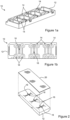
Figure 1 (a) is an isometric view of a first embodiment of a microfluidic platform according to the present invention; -
Figure 1 (b) is a plan view of the microfluidic platform ofFigure 1 (a) ; -
Figure 2 is a cross-sectional view of the microfluidic platform ofFigure 1 showing a preferred arrangement of the chip base and gas permeable laminate; -
Figure 3 is a cross-sectional view of a prior art microfluidic platform showing a configuration of conventional ports; -
Figure 4 is a cross-sectional view of a microfluidic platform according to the present invention showing a preferred configuration of improved ports; -
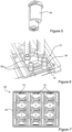
Figure 5 illustrates a preferred modular luer connector that can be employed with a microfluidic platform according to the present invention; -
Figure 6 illustrates modular luer connectors connected to the ports in a microfluidic platform according to the present invention; -
Figure 7 is a plan view of one embodiment of a microplate holder for holding up to three microfluidic platforms according to the present invention; -
Figure 8 is an isometric view of both the topside and underside of the microfluidic platform ofFigure 1 , illustrating the location of internal reservoirs provided therein; -
Figure 9 illustrates the location of internal reservoirs provided in the microplate holder ofFigure 7 ; -
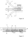
Figure 10 is an enlarged bottom of a preferred embodiment of the microfluidic channels in the microfluidic platform ofFigure 1 ; and, -
Figure 11 is an enlarged cross-section view of the microfluidic channels through the line A-A inFigure 10 . - A preferred embodiment of a
microfluidic platform 10 for investigating cell-based interactions in accordance with the invention, as illustrated inFigures 1 and 2 , comprises achip base 12 made of a suitable plastics material with the appropriate optical properties. Thechip base 12 has a plurality ofports 14 in fluid communication with amicrofluidic channel 16 for containing aculture medium 17 in which cells are held. - Typically the
chip base 12 has a plurality ofmicrofluidic channels 16 of elongate configuration arranged in a linear array, eachmicrofluidic channel 16 being substantially parallel to an adjacent channel, as can be seen most clearly inFigures 10 and 11 . Eachmicrofluidic channel 16 has first andsecond ports 14 provided at each end respectively, as can be seen most clearly inFigure 4 . Preferably theports 14 all open onto an upper surface of thechip base 12. Typically thechip base 12 is of generally elongate, rectangular configuration, with theports 14 arranged along its respective longitudinal edges. Typical dimensions of thechip base 12 are 75 mm in length, 25 mm in width, and 6 mm in depth. Themicrofluidic channels 16 are typically 250 microns deep. - Preferably the
microfluidic channels 16 are arranged intopairs microfluidic channel 16c provided there between, as illustrated inFigures 10 and 11 . Thethird channel 16c is arranged so as to permit controlled fluid communication between the pair ofmicrofluidic channels microfluidic channel 16c. Typically the thirdmicrofluidic channel 16c is filled with ahydrogel 18 or other extracellular matrix. - Preferably the
chip base 12 is made from an engineering plastics material that can be injection molded and is optically clear. Typically the plastics material is selected from the group consisting of (but not limited to): polycarbonates (PC), polystyrenes (PS), polyethylenes (PE), cyclic olefin co-polymers (COC), cyclic olefin polymers (COP). - Plastics such as polycarbonate, polystyrene, etc. have historically been used to make cell culture devices in large scales. Traditional cell culture devices are flasks or wells that have large air head spaces and media volumes, so gas exchange is easily achieved. However, microfluidic devices consist of small volumes in sealed channels, and gas exchange becomes a limiting factor as most plastics are gas impermeable. This limitation may be been overcome by combining the
plastic chip base 14 with a gaspermeable laminate 20. - Preferably the gas
permeable laminate 20 is optically clear and is made from a polymer with low bulk density. Typically the polymer of low bulk density is selected from the group consisting of: polymethylpentene (PMP) and poly(1-trimethylsilyl-1-propyne) (PTMSP), or from polymethylated polymers such as polymethylated poly(diphenylacetylene), or from polymers that achieve sufficient gas permeability through other means. Preferably all of themicrofluidic channels 16 are formed in a bottom surface of thechip base 12 and the gaspermeable laminate 20 is bonded to the bottom surface of the chip base to enclose thechannels 16 as shown inFigures 2 and11 . Typically the laminate 20 is bonded to thechip base 12 by heat lamination, solvent bonding, adhesion (with wet or dry adhesives), or by other means depending on the specific materials used for thechip base 12 andlaminate 20 respectively. - It is also possible to make the
chip base 12 entirely out of the gas permeable polymer. Doing so may have advantages in providing a simpler lamination process, since both the laminate 20 andchip base 12 would then have identical material properties. However there may not be a significant gain in oxygen availability because the oxygen has to diffuse across a thick chip base (in the order of millimeters) versus a thin laminate (in the order of tens to hundreds of micrometers). The specialised gas permeable plastics may also have material properties that make them unsuitable for injection molding. For these reasons, in the preferred embodiment thechip base 12 is fabricated out of standard injection moldable plastics and the device is laminated with a thin gas permeable laminate . - The microfluidic platform or
chip 10 of the present invention is capable of replicating the in vivo behavior of cells in a culture system. Applications of the microfluidic platform orchip 10 may include (but are not limited to): - Research tools for academic and industrial RandD
- Drug discovery tools for pharmaceutical companies
- Assistive tools for tailoring clinical therapies to individual patients
- Ease of use is a critical differentiator for the academic RandD customer segment. Besides the inconvenience of PDMS chip fabrication, users face other usage difficulties including:
- Daily changing of media - Microfluidic devices have small culture media volumes within each channel (typically tens of microliters). This means that the nutrient content of the medium will be exhausted quickly by the cultured cells, and the medium must be changed daily. Since users have to change media for many small devices, the process needs to be simple, rapid and error-proof. Culture medium is typically aspirated out of the microfluidic channels with a pipette tip attached to vacuum suction. A common error that occurs is over-aspiration where too much vacuum force is applied, resulting in cells being sucked out of the channels along with the culture medium, resulting in cell loss/death.
- Flexibility: Researchers value the flexibility to experiment with different setups, e.g. by connecting other devices and equipment to the culture system to modify the culture conditions. Current users have to fashion their own connections, which may be inconvenient and unreliable.
- Handling: Users want microfluidic chips that make optimal use of the limited space in their incubators. The chips also need to be transported to tissue culture hoods and to various microscope platforms without spillage or contamination. Automated handling of devices (by robotic platforms, for example) is limited to certain form factors like microtiter plates.
- Evaporation control - Microfluidic devices have small culture media volumes, so evaporation loss will cause significant changes in media osmolarity, resulting in unfavourable culture conditions. Users have to set up humidity chambers inside incubators to combat evaporation.
- A number of innovations have been incorporated into the preferred embodiment of the microfluidic platform or
chip 10 to overcome the usage difficulties outlined above. These additional innovations will now be described in detail. - Prior art microfluidic port designs are cylindrical in shape, leading directly into the channels (see
Figure 3 ). Vacuum suction during the changing of culture medium can lead to cells being sucked out of the channels. An improved port design involves making internal troughs that are deeper than internal inlets (seeFigure 4 ). Eachport 14 has aninternal inlet 22, connecting theport 14 with themicrofluidic channel 16, and atrough 24 for containing a small reservoir of culture medium fluid adjacent to theinlet 22 wherein, in use, culture medium can be aspirated from themicrofluidic channel 16 via thetrough 24 rather than directly via theinternal inlet 22. - In the illustrated embodiment the
inlet 22 is provided centrally of theport 14 and thetrough 24 is of annular configuration surrounding the inlet in a concentric circle (as shown in cross-section inFigure 4 ). Alternatively, thetrough 24 may be of a different configuration yet still placed adjacent to theinlet 22. Typically the bottom of the trough is of semicircular cross-section. - The application of a vacuum through a glass/
pipette tip 26 placed in thetrough 24, as shown inFigure 4 , results in the removal of culture medium fluid, stopping when the medium in the trough is completely removed. Due to the higher height of theinternal inlet 22, the culture medium and cells in the channel would not be affected by the vacuum aspiration, no matter how long the pipette tip is kept in thetrough 24. Fresh medium can then be added to the port on one side of the channel 16 (the 'upstream' port), and allowed to flow through the channel, replacing the old medium. As a consequence of surface tension effects in microfluidic systems, a small volume of fresh media may need to be added to the downstream port, so that surface tension at the downstream inlet can be overcome to allow incoming flow. - The
chip channel ports 14 are preferably designed as modular attachment interfaces. AIM's universal luer lock connector 30 (as shown inFigure 5 ) enables users to attach standard luer fittings (e.g. for attaching tubing connectors and syringe pumps) to themicrofluidic chip 10. Future accessories developed by AIM may connect directly to theports 14 or via the universal connectors.Figure 5 shows a plurality of themodular connectors 30 connected torespective ports 14 of themicrofluidic platform 10.Figure 5 shows both a connector for luer slip and luer lock connections (left), and connectors attached to luer slip and luer lock syringes (right). - Prior art approaches by other manufacturers are based on separate components built directly onto the chip. The connector components protrude out of the chip and are included in the chip by default. This present modular design has two important advantages:
- (i) The
microfluidic chips 10 can be made more efficiently out of a single material into a single component - Not all users want to connect to other devices. These users will have the option to use thebasic chip 10 on its own. Other users that require connections to other devices have a separate option to use modular luer connectors. This design approach makes more economic sense to both the manufacturer and users, because the core platform (i.e. the chip) would be easier to manufacture, while the user community will get a lower price base and yet have more choices. - (ii) The ports play dual roles - The ports act as reservoirs that enable rapid media changing for users that do not require connections. Other users that need to connect to syringe pumps, etc. would use the ports as connecting interfaces. Note that the latter group of users would exchange media by using the connected devices such as pumps, so there is no need for the rapid media changing function. This approach optimises the use of the limited real estate on the chip. It also enables future accessories to be attached directly onto the chip itself with an interface that matches the port's trough and inlet, doing away with the extra component that other manufacturers use today.
- Advantageously a plurality of the
microfluidic chips 10 can be received and held in asingle microplate holder 40, as shown inFigures 7 and9 . The illustrated embodiment of themicroplate holder 40 comprises atray 42, having side walls and a substantially planar base, and a plurality of compartments 46 provided in connection therewith. Each compartment 46 in thetray 42 is adapted to receive amicrofluidic chip 10 therein. In the illustrated embodiment thetray 42 is designed to receive up to three of thefluidic chips 10 therein. Preferably theholder 40 further comprises acover 44 which is received on top of the tray to enclose themicrofluidic chips 10 therein. Advantageously thecover 44 is substantially transparent. Advantageously a plurality of theholders 40 is also stackable. - Standard form factors such as microscope slides and microtiter plates are prevalent in the biological and pharmaceutical research industries. Both the chips and holders are designed to comply with these existing standards so that the devices fit into existing workflows. The holders will also fit onto standard microscopy platforms and are stackable to maximise working space in cell culture incubators. The holders are designed to position the
chip channel ports 14 to comply with SBS/ANSI standards for microtiter plates, so that they will be compatible with automated plate filling/handling systems. Such systems are made to fill wells in microplates and require the fill positions to be accurately located. A further advantage of this design approach is that devices suitable for manual operation in academic laboratories can also be deployed in an industrial, automated setting. - Users of microfluidic systems often have to place their devices in humidity chambers to limit evaporation. Advantageously both the
chips 10 andholders 40 have built-in reservoirs (seeFigures 8 and 9 ) that can be filled with sterile water, hydrogels (e.g. agarose, polyacrylamide, etc.) or other substances to create a humid environment around the device (and within the holder). This approach does away with the need to set up a separate humidity chamber. It also facilitates easy handling and retention of humid conditions when transferring the devices onto imaging platforms, since the humidification function is built into the chips and holders themselves. - As can be seen most clearly in
Figure 8 , thechip base 12 is formed with a plurality ofreservoirs 50 molded into an upper surface thereof. Thereservoirs 50 are not in fluid communication with theports 14. In use, each reservoir can be used to hold sterile water, a hydrogel or other substance to create a humid environment around the device. - Likewise the
holder 40 further comprises a plurality ofinternal reservoirs 60 provided within thetray 42, as can be seen most clearly inFigure 9 . Thereservoirs 60 are separate from and not in fluid communication with thechips 10. Hence, in use, eachreservoir 60 can be used to hold sterile water, a hydrogel or other substance to create a humid environment around thechips 10. - Now that preferred embodiments of the microfluidic platform have been described in detail, it will be apparent that it provides a number of advantages over the prior art, including the following:
- (i) It overcomes the problems associated with using PDMS for the substrate of the chip;
- (ii) Improved chip channel port design obviates the problems associated with over-aspiration;
- (iii) The chip can be used on its own, or in conjunction with other devices using modular luer connectors;
- (iv) Both chips and holders comply with SBS/ANSI standards for microtiter plates, so they are compatible with automated plate filling/handling systems; and,
- (v) Built-in reservoirs allow both the chips and holders to provide on-board humidity control.
- For example, the fluidic platforms or chips in the described embodiments are each provided with three sets of microfluidic channels. However the chips can be custom-designed to incorporate any desired number of channels and in a variety of configurations. Therefore, it will be appreciated that the scope of the invention is not limited to the specific embodiments described.
Claims (14)
- A microfluidic platform (10) for investigating cell-based interactions, the platform comprising:a chip base (12) made of a suitable plastics material with the appropriate optical properties, the chip base (12) having a plurality of ports (14) in fluid communication with a microfluidic channel (16) for containing a culture medium in which cells are held;wherein each port (14) has an internal inlet (22), connecting the port (14) with the microfluidic channel (16), and a trough (24) for containing a small reservoir of culture medium fluid adjacent to the inlet (22), wherein, in use, culture medium can be aspirated from the microfluidic channel via the trough rather than directly via the internal inlet and each port has an upper reservoir above said trough and said internal inlet, wherein the trough (24) is deeper than the internal inlet (22).
- A microfluidic platform (10) as defined in claim 1, wherein the chip base is made from an engineering plastics material that can be injection molded and is optically clear, preferably wherein the plastics material is selected from the group consisting of: polycarbonates (PC), polystyrenes (PS), polyethylenes (PE), cyclic olefin co-polymers (COC), cyclic olefin polymers (COP).
- A microfluidic platform (10) as defined in claim 1 or claim 2, further comprising a gas permeable laminate (20) bonded to a bottom surface of the chip base (12), preferably wherein the gas permeable laminate is:(i) made from a polymer with low bulk density; or(ii) optically clear.
- A microfluidic platform (10) as defined in claim 3, wherein the laminate (20) is bonded to the chip base (12) by heat lamination, solvent bonding, adhesion (with wet or dry adhesives), or by other means depending on the specific materials used for the chip base and laminate respectively.
- A microfluidic platform (10) as defined in claim 1, wherein the chip base (12) has a plurality of microfluidic channels (16) of elongate configuration arranged in a linear array, each microfluidic channel being substantially parallel to an adjacent channel, preferably wherein each microfluidic channel has a pair of ports (14), one port provided at each end respectively.
- A microfluidic platform (10) as defined in claim 5, wherein:(i) the ports (14) all open onto an upper surface of the chip base (12); or(ii) the microfluidic channels are arranged into pairs (16a, 16b) with a third microfluidic channel (16c) provided there between, the third channel being configured so as to permit controlled fluid communication between the pair of microfluidic channels and the third microfluidic channel, preferably wherein the third microfluidic channel is filled with a hydrogel (18) or other extracellular matrix.
- A microfluidic platform (10) as defined in claim 5 or claim 6, wherein all of the microfluidic channels (16) are formed in a bottom surface of the chip base (10) and a gas permeable laminate (20) is bonded to the bottom surface of the chip base to enclose the channels.
- A microfluidic platform (10) as defined in claim 5, wherein the chip base (12) is formed with a plurality of reservoirs (50) molded into the upper surface thereof which are not in fluid communication with the ports (14), wherein, in use, each reservoir is adapted to hold sterile water, a hydrogel or other substance to create a humid environment around the device.
- A microfluidic platform (10) as defined in claim 1, wherein the chip base (12) is of generally elongate, rectangular configuration, with the ports (14) arranged along its respective longitudinal edges.
- A microfluidic platform (10) as defined in claim 1, wherein:(i) the inlet (22) is provided centrally of the port and the trough (24) is of annular configuration surrounding the inlet, preferably wherein the bottom of the trough is of semicircular cross-section; or(ii) the ports (14) of the microfluidic platform are designed as modular attachment interfaces, preferably wherein the ports are adapted to receive a modular luer connector for attaching standard luer fittings, such as tubing connectors and syringe pumps to the microfluidic platform; or(iii) a plurality of the microfluidic platforms can be received and held in a single microplate holder (40), preferably wherein the holder further comprises a plurality of internal reservoirs (60), which are not in fluid communication with the chips, wherein, in use, each reservoir is adapted to hold sterile water, a hydrogel or other substance to create a humid environment around the chips.
- A method of manufacturing a microfluidic platform for investigating cell-based interactions, the method comprising the steps of:molding a chip base (12) from a suitable plastics material with appropriate optical properties, the chip base having a plurality of ports (14) in fluid communication with a microfluidic channel for containing a culture medium in which cells are held;wherein each port has an internal inlet (22), connecting the port with the microfluidic channel, and a trough (24) for containing a small reservoir of culture medium fluid adjacent to the inlet, wherein, in use, culture medium can be aspirated from the microfluidic channel via the trough rather than directly via the internal inlet and each port has an upper reservoir above said trough andsaid internal inlet, wherein the internal trough is deeper than the internal inlet.
- A method of manufacturing a microfluidic platform as defined in claim 11, wherein:(i) the step of molding the chip base (12) involves injection molding using an engineering plastics material that is optically clear, preferably wherein the plastics material is selected from the group consisting of: polycarbonates (PC), polystyrenes (PS), polyethylenes (PE), cyclic olefin co-polymers (COC), and cyclic olefin polymers (COP); or(ii) the method further comprises the step of bonding a gas permeable laminate (20) to a bottom surface of the chip base, preferably wherein the gas permeable laminate is optically clear and is made from a polymer with low bulk density.
- A microfluidic platform (10) as defined in claim 3 or a method of manufacturing a microfluidic platform as defined in claim 12, part (ii), wherein the polymer of low bulk density is selected from the group consisting of: polymethylpentene (PMP) and poly(1-trimethylsilyl-1-propyne) (PTMSP), polymethylated polymers such as polymethylated poly(diphenylacetylene), or polymers that achieve sufficient gas permeability through other means.
- A method of manufacturing a microfluidic platform as defined in claim 12, part (ii), wherein the step of bonding the laminate (20) to the chip base (12) involves:(i) laminating the laminate to the chip base by heat lamination; or(ii) solvent bonding, adhesion bonding (with wet or dry adhesives), or other bonding means depending on the specific materials used for the chip base and laminate respectively.
Applications Claiming Priority (2)
| Application Number | Priority Date | Filing Date | Title |
|---|---|---|---|
| US201462077942P | 2014-11-11 | 2014-11-11 | |
| PCT/SG2015/050441 WO2016076795A1 (en) | 2014-11-11 | 2015-11-09 | Microfluidic platform for investigating cell-based interactions |
Publications (3)
| Publication Number | Publication Date |
|---|---|
| EP3218300A1 EP3218300A1 (en) | 2017-09-20 |
| EP3218300A4 EP3218300A4 (en) | 2018-07-18 |
| EP3218300B1 true EP3218300B1 (en) | 2024-10-02 |
Family
ID=55954736
Family Applications (1)
| Application Number | Title | Priority Date | Filing Date |
|---|---|---|---|
| EP15859297.2A Active EP3218300B1 (en) | 2014-11-11 | 2015-11-09 | Microfluidic platform for investigating cell-based interactions |
Country Status (9)
| Country | Link |
|---|---|
| US (1) | US10711234B2 (en) |
| EP (1) | EP3218300B1 (en) |
| JP (1) | JP6857123B2 (en) |
| KR (1) | KR102260910B1 (en) |
| CN (1) | CN107108199B (en) |
| CA (1) | CA3004596C (en) |
| DK (1) | DK3218300T3 (en) |
| SG (1) | SG11201809990TA (en) |
| WO (1) | WO2016076795A1 (en) |
Families Citing this family (13)
| Publication number | Priority date | Publication date | Assignee | Title |
|---|---|---|---|---|
| WO2019083447A1 (en) * | 2017-10-23 | 2019-05-02 | National University Of Singapore | Planar modular microfluidic system |
| JP7388724B2 (en) * | 2018-10-29 | 2023-11-29 | 国立大学法人 東京大学 | Artificial multilayer tissue culture device and method for producing artificial multilayer tissue |
| TW202039819A (en) * | 2018-11-07 | 2020-11-01 | 日商牛尾電機股份有限公司 | Cell culturing chip |
| WO2020264303A1 (en) | 2019-06-27 | 2020-12-30 | EMULATE, Inc. | Compound distribution in microfluidic devices |
| TR201909710A2 (en) * | 2019-06-28 | 2021-01-21 | Koc Ueniversitesi | A MICROFLUID PLATFORM TO ENABLE CULTIVATION OF CELLS IN A THREE-DIMENSIONAL MICRO-PERIPHERAL |
| IL292337A (en) * | 2019-10-21 | 2022-06-01 | Flaskworks Llc | Cell culture systems and methods |
| EP3892713A1 (en) * | 2020-04-08 | 2021-10-13 | Cellectricon Ab | Multi-well plates for creation of high-density arrays of compartmentalized cell cultures for usage in high capacity applications |
| JP7543710B2 (en) * | 2020-06-04 | 2024-09-03 | ウシオ電機株式会社 | Microfluidic Devices |
| DE102021204675B4 (en) | 2021-05-07 | 2023-05-17 | Lpkf Laser & Electronics Se | Device and method for cell cultivation |
| EP4289933A1 (en) | 2022-06-07 | 2023-12-13 | ibidi GmbH | Cell culture substrate |
| WO2023242189A1 (en) | 2022-06-13 | 2023-12-21 | Eth Zurich | Collagen visualization on microfluidic device |
| US20240368514A1 (en) * | 2023-05-05 | 2024-11-07 | Kuhner Shaker Inc. | Sbs-format single, or dual, deep well stackable cell culture disposable well plate and closure |
| EP4481029A1 (en) | 2023-06-22 | 2024-12-25 | Cherry Biotech SAS | Method for controlling fluid displacement and gas(es) composition and/or ph in a cell culture device and corresponding cell culture system |
Family Cites Families (20)
| Publication number | Priority date | Publication date | Assignee | Title |
|---|---|---|---|---|
| US6090251A (en) * | 1997-06-06 | 2000-07-18 | Caliper Technologies, Inc. | Microfabricated structures for facilitating fluid introduction into microfluidic devices |
| US6582964B1 (en) * | 1999-05-12 | 2003-06-24 | Cme Telemetrix Inc. | Method and apparatus for rapid measurement of HbA1c |
| AU2002243360A1 (en) * | 2000-12-26 | 2002-08-06 | C. Frederick Battrell | Microfluidic cartridge with integrated electronics |
| US20050266582A1 (en) * | 2002-12-16 | 2005-12-01 | Modlin Douglas N | Microfluidic system with integrated permeable membrane |
| WO2004089810A2 (en) * | 2003-04-03 | 2004-10-21 | Fluidigm Corp. | Microfluidic devices and methods of using same |
| JP2005027659A (en) * | 2003-06-20 | 2005-02-03 | Nitto Denko Corp | Cell microchip |
| GB0321158D0 (en) * | 2003-09-10 | 2003-10-08 | Central Research Lab Ltd | Apparatus and method for handling cells,embryos or oocytes |
| US20060252087A1 (en) * | 2005-01-18 | 2006-11-09 | Biocept, Inc. | Recovery of rare cells using a microchannel apparatus with patterned posts |
| WO2007002580A2 (en) * | 2005-06-23 | 2007-01-04 | Bioveris Corporation | Diagnostic as say system with multi -well reagent container |
| MX346456B (en) * | 2008-02-27 | 2017-03-21 | Boehringer Ingelheim Microparts Gmbh | Apparatus for the separation of plasma. |
| CN103635587A (en) | 2008-04-08 | 2014-03-12 | 麻省理工学院 | Three-dimensional microfluidic platforms and methods of use thereof |
| WO2010023497A1 (en) * | 2008-08-29 | 2010-03-04 | Peking University | A microfluidic chip for accurately controllable cell culture |
| US20100056394A1 (en) | 2008-09-04 | 2010-03-04 | Chung Yuan Christian University | Mini Bio-Reactor |
| US20110250690A1 (en) | 2008-11-11 | 2011-10-13 | Craig H Randall | Microfluidic Embryo and Gamete Culture Systems |
| JP5847733B2 (en) * | 2010-01-28 | 2016-01-27 | ザ リージェンツ オブ ザ ユニバーシティ オブ ミシガン | Hanging drop array plate |
| JP6170431B2 (en) * | 2010-09-29 | 2017-07-26 | マサチューセッツ インスティテュート オブ テクノロジー | Devices for high-throughput studies of cell-cell interactions |
| JP2012194062A (en) * | 2011-03-16 | 2012-10-11 | Tokyo Denki Univ | Microfluid chip and microfluid system using the same |
| CA2842359A1 (en) * | 2011-08-01 | 2013-02-07 | Denovo Sciences | Cell capture system and method of use |
| JP2013076591A (en) * | 2011-09-30 | 2013-04-25 | Sumitomo Bakelite Co Ltd | Microchannel device and method for manufacturing the same |
| JP6302187B2 (en) * | 2012-08-13 | 2018-03-28 | キヤノン株式会社 | Microchannel chip and manufacturing method thereof |
-
2015
- 2015-11-09 JP JP2017526142A patent/JP6857123B2/en active Active
- 2015-11-09 CN CN201580072922.6A patent/CN107108199B/en active Active
- 2015-11-09 DK DK15859297.2T patent/DK3218300T3/en active
- 2015-11-09 EP EP15859297.2A patent/EP3218300B1/en active Active
- 2015-11-09 US US15/525,937 patent/US10711234B2/en active Active
- 2015-11-09 KR KR1020177016048A patent/KR102260910B1/en active Active
- 2015-11-09 SG SG11201809990TA patent/SG11201809990TA/en unknown
- 2015-11-09 CA CA3004596A patent/CA3004596C/en active Active
- 2015-11-09 WO PCT/SG2015/050441 patent/WO2016076795A1/en not_active Ceased
Also Published As
| Publication number | Publication date |
|---|---|
| WO2016076795A1 (en) | 2016-05-19 |
| CA3004596C (en) | 2021-07-27 |
| CN107108199B (en) | 2020-01-10 |
| US10711234B2 (en) | 2020-07-14 |
| JP2017533725A (en) | 2017-11-16 |
| KR102260910B1 (en) | 2021-06-04 |
| EP3218300A1 (en) | 2017-09-20 |
| JP6857123B2 (en) | 2021-04-14 |
| KR20170078841A (en) | 2017-07-07 |
| DK3218300T3 (en) | 2025-01-02 |
| EP3218300A4 (en) | 2018-07-18 |
| US20180327700A1 (en) | 2018-11-15 |
| CA3004596A1 (en) | 2016-05-19 |
| CN107108199A (en) | 2017-08-29 |
| SG11201809990TA (en) | 2018-12-28 |
Similar Documents
| Publication | Publication Date | Title |
|---|---|---|
| CA3004596C (en) | Microfluidic platform for investigating cell-based interactions | |
| EP1667589B1 (en) | Apparatus for handling cells, embryos or oocytes | |
| US7005109B2 (en) | System for handling liquid samples | |
| EP3173787B1 (en) | Cell culture array system for automated assays and methods of operation and manufacture thereof | |
| JP7231619B2 (en) | well plate assembly | |
| US9739699B2 (en) | Device for the study of living cells | |
| JP2017526352A (en) | Fluid circulation system incorporating a fluid leveling device | |
| CA3045155C (en) | Methods and apparatus for perfusion and environmental control of microplate labware | |
| US20140363838A1 (en) | Microperfusion imaging platform | |
| JP2015073468A (en) | Cell culture apparatus, and cell culture method | |
| CN212833791U (en) | Micro-fluidic chip for cell function detection | |
| Mansouri et al. | Transforming static barrier tissue models into dynamic microphysiological systems | |
| WO2024182388A1 (en) | Apparatus containing multiple microfluidic assay devices with scaffold regions | |
| US20170158999A1 (en) | Modular bioreactor for culture of biopaper based tissues | |
| WO2024261021A1 (en) | Fluidic device and use of the same | |
| EP4731338A1 (en) | Fluidic device and use of the same | |
| CN121950498A (en) | Microfluidic sample device and method for manufacturing a microfluidic detection device |
Legal Events
| Date | Code | Title | Description |
|---|---|---|---|
| STAA | Information on the status of an ep patent application or granted ep patent |
Free format text: STATUS: THE INTERNATIONAL PUBLICATION HAS BEEN MADE |
|
| PUAI | Public reference made under article 153(3) epc to a published international application that has entered the european phase |
Free format text: ORIGINAL CODE: 0009012 |
|
| STAA | Information on the status of an ep patent application or granted ep patent |
Free format text: STATUS: REQUEST FOR EXAMINATION WAS MADE |
|
| 17P | Request for examination filed |
Effective date: 20170609 |
|
| AK | Designated contracting states |
Kind code of ref document: A1 Designated state(s): AL AT BE BG CH CY CZ DE DK EE ES FI FR GB GR HR HU IE IS IT LI LT LU LV MC MK MT NL NO PL PT RO RS SE SI SK SM TR |
|
| AX | Request for extension of the european patent |
Extension state: BA ME |
|
| DAV | Request for validation of the european patent (deleted) | ||
| DAX | Request for extension of the european patent (deleted) | ||
| A4 | Supplementary search report drawn up and despatched |
Effective date: 20180618 |
|
| RIC1 | Information provided on ipc code assigned before grant |
Ipc: C12M 1/32 20060101ALI20180612BHEP Ipc: C12M 3/06 20060101ALI20180612BHEP Ipc: C12M 1/00 20060101ALI20180612BHEP Ipc: B81C 1/00 20060101ALI20180612BHEP Ipc: B01L 3/00 20060101ALI20180612BHEP Ipc: B81B 1/00 20060101AFI20180612BHEP Ipc: C12M 3/00 20060101ALI20180612BHEP |
|
| RIN1 | Information on inventor provided before grant (corrected) |
Inventor name: KUAN, CHEE MUN Inventor name: PAVESI, ANDREA Inventor name: LIM, SEI HIEN Inventor name: LIM, SWEE KHUAN |
|
| STAA | Information on the status of an ep patent application or granted ep patent |
Free format text: STATUS: EXAMINATION IS IN PROGRESS |
|
| 17Q | First examination report despatched |
Effective date: 20220329 |
|
| GRAP | Despatch of communication of intention to grant a patent |
Free format text: ORIGINAL CODE: EPIDOSNIGR1 |
|
| STAA | Information on the status of an ep patent application or granted ep patent |
Free format text: STATUS: GRANT OF PATENT IS INTENDED |
|
| INTG | Intention to grant announced |
Effective date: 20240424 |
|
| GRAS | Grant fee paid |
Free format text: ORIGINAL CODE: EPIDOSNIGR3 |
|
| GRAA | (expected) grant |
Free format text: ORIGINAL CODE: 0009210 |
|
| STAA | Information on the status of an ep patent application or granted ep patent |
Free format text: STATUS: THE PATENT HAS BEEN GRANTED |
|
| AK | Designated contracting states |
Kind code of ref document: B1 Designated state(s): AL AT BE BG CH CY CZ DE DK EE ES FI FR GB GR HR HU IE IS IT LI LT LU LV MC MK MT NL NO PL PT RO RS SE SI SK SM TR |
|
| REG | Reference to a national code |
Ref country code: GB Ref legal event code: FG4D |
|
| REG | Reference to a national code |
Ref country code: CH Ref legal event code: EP |
|
| REG | Reference to a national code |
Ref country code: IE Ref legal event code: FG4D |
|
| REG | Reference to a national code |
Ref country code: DE Ref legal event code: R096 Ref document number: 602015090050 Country of ref document: DE |
|
| REG | Reference to a national code |
Ref country code: DK Ref legal event code: T3 Effective date: 20241217 |
|
| REG | Reference to a national code |
Ref country code: SE Ref legal event code: TRGR |
|
| REG | Reference to a national code |
Ref country code: NL Ref legal event code: FP |
|
| REG | Reference to a national code |
Ref country code: LT Ref legal event code: MG9D |
|
| P01 | Opt-out of the competence of the unified patent court (upc) registered |
Free format text: CASE NUMBER: APP_68295/2024 Effective date: 20241226 |
|
| REG | Reference to a national code |
Ref country code: AT Ref legal event code: MK05 Ref document number: 1728351 Country of ref document: AT Kind code of ref document: T Effective date: 20241002 |
|
| PG25 | Lapsed in a contracting state [announced via postgrant information from national office to epo] |
Ref country code: IS Free format text: LAPSE BECAUSE OF FAILURE TO SUBMIT A TRANSLATION OF THE DESCRIPTION OR TO PAY THE FEE WITHIN THE PRESCRIBED TIME-LIMIT Effective date: 20250202 Ref country code: HR Free format text: LAPSE BECAUSE OF FAILURE TO SUBMIT A TRANSLATION OF THE DESCRIPTION OR TO PAY THE FEE WITHIN THE PRESCRIBED TIME-LIMIT Effective date: 20241002 Ref country code: PT Free format text: LAPSE BECAUSE OF FAILURE TO SUBMIT A TRANSLATION OF THE DESCRIPTION OR TO PAY THE FEE WITHIN THE PRESCRIBED TIME-LIMIT Effective date: 20250203 |
|
| PG25 | Lapsed in a contracting state [announced via postgrant information from national office to epo] |
Ref country code: FI Free format text: LAPSE BECAUSE OF FAILURE TO SUBMIT A TRANSLATION OF THE DESCRIPTION OR TO PAY THE FEE WITHIN THE PRESCRIBED TIME-LIMIT Effective date: 20241002 |
|
| PG25 | Lapsed in a contracting state [announced via postgrant information from national office to epo] |
Ref country code: BG Free format text: LAPSE BECAUSE OF FAILURE TO SUBMIT A TRANSLATION OF THE DESCRIPTION OR TO PAY THE FEE WITHIN THE PRESCRIBED TIME-LIMIT Effective date: 20241002 |
|
| PG25 | Lapsed in a contracting state [announced via postgrant information from national office to epo] |
Ref country code: ES Free format text: LAPSE BECAUSE OF FAILURE TO SUBMIT A TRANSLATION OF THE DESCRIPTION OR TO PAY THE FEE WITHIN THE PRESCRIBED TIME-LIMIT Effective date: 20241002 |
|
| PG25 | Lapsed in a contracting state [announced via postgrant information from national office to epo] |
Ref country code: NO Free format text: LAPSE BECAUSE OF FAILURE TO SUBMIT A TRANSLATION OF THE DESCRIPTION OR TO PAY THE FEE WITHIN THE PRESCRIBED TIME-LIMIT Effective date: 20250102 |
|
| PG25 | Lapsed in a contracting state [announced via postgrant information from national office to epo] |
Ref country code: LV Free format text: LAPSE BECAUSE OF FAILURE TO SUBMIT A TRANSLATION OF THE DESCRIPTION OR TO PAY THE FEE WITHIN THE PRESCRIBED TIME-LIMIT Effective date: 20241002 Ref country code: GR Free format text: LAPSE BECAUSE OF FAILURE TO SUBMIT A TRANSLATION OF THE DESCRIPTION OR TO PAY THE FEE WITHIN THE PRESCRIBED TIME-LIMIT Effective date: 20250103 Ref country code: AT Free format text: LAPSE BECAUSE OF FAILURE TO SUBMIT A TRANSLATION OF THE DESCRIPTION OR TO PAY THE FEE WITHIN THE PRESCRIBED TIME-LIMIT Effective date: 20241002 |
|
| PG25 | Lapsed in a contracting state [announced via postgrant information from national office to epo] |
Ref country code: CZ Free format text: LAPSE BECAUSE OF FAILURE TO SUBMIT A TRANSLATION OF THE DESCRIPTION OR TO PAY THE FEE WITHIN THE PRESCRIBED TIME-LIMIT Effective date: 20241002 Ref country code: PL Free format text: LAPSE BECAUSE OF FAILURE TO SUBMIT A TRANSLATION OF THE DESCRIPTION OR TO PAY THE FEE WITHIN THE PRESCRIBED TIME-LIMIT Effective date: 20241002 |
|
| PG25 | Lapsed in a contracting state [announced via postgrant information from national office to epo] |
Ref country code: RS Free format text: LAPSE BECAUSE OF FAILURE TO SUBMIT A TRANSLATION OF THE DESCRIPTION OR TO PAY THE FEE WITHIN THE PRESCRIBED TIME-LIMIT Effective date: 20250102 |
|
| PG25 | Lapsed in a contracting state [announced via postgrant information from national office to epo] |
Ref country code: SM Free format text: LAPSE BECAUSE OF FAILURE TO SUBMIT A TRANSLATION OF THE DESCRIPTION OR TO PAY THE FEE WITHIN THE PRESCRIBED TIME-LIMIT Effective date: 20241002 |
|
| REG | Reference to a national code |
Ref country code: DE Ref legal event code: R097 Ref document number: 602015090050 Country of ref document: DE |
|
| PG25 | Lapsed in a contracting state [announced via postgrant information from national office to epo] |
Ref country code: MC Free format text: LAPSE BECAUSE OF FAILURE TO SUBMIT A TRANSLATION OF THE DESCRIPTION OR TO PAY THE FEE WITHIN THE PRESCRIBED TIME-LIMIT Effective date: 20241002 |
|
| PG25 | Lapsed in a contracting state [announced via postgrant information from national office to epo] |
Ref country code: LU Free format text: LAPSE BECAUSE OF NON-PAYMENT OF DUE FEES Effective date: 20241109 |
|
| PG25 | Lapsed in a contracting state [announced via postgrant information from national office to epo] |
Ref country code: EE Free format text: LAPSE BECAUSE OF FAILURE TO SUBMIT A TRANSLATION OF THE DESCRIPTION OR TO PAY THE FEE WITHIN THE PRESCRIBED TIME-LIMIT Effective date: 20241002 |
|
| PG25 | Lapsed in a contracting state [announced via postgrant information from national office to epo] |
Ref country code: RO Free format text: LAPSE BECAUSE OF FAILURE TO SUBMIT A TRANSLATION OF THE DESCRIPTION OR TO PAY THE FEE WITHIN THE PRESCRIBED TIME-LIMIT Effective date: 20241002 |
|
| PG25 | Lapsed in a contracting state [announced via postgrant information from national office to epo] |
Ref country code: SK Free format text: LAPSE BECAUSE OF FAILURE TO SUBMIT A TRANSLATION OF THE DESCRIPTION OR TO PAY THE FEE WITHIN THE PRESCRIBED TIME-LIMIT Effective date: 20241002 |
|
| PLBE | No opposition filed within time limit |
Free format text: ORIGINAL CODE: 0009261 |
|
| STAA | Information on the status of an ep patent application or granted ep patent |
Free format text: STATUS: NO OPPOSITION FILED WITHIN TIME LIMIT |
|
| REG | Reference to a national code |
Ref country code: BE Ref legal event code: MM Effective date: 20241130 |
|
| 26N | No opposition filed |
Effective date: 20250703 |
|
| PG25 | Lapsed in a contracting state [announced via postgrant information from national office to epo] |
Ref country code: BE Free format text: LAPSE BECAUSE OF NON-PAYMENT OF DUE FEES Effective date: 20241130 |
|
| PG25 | Lapsed in a contracting state [announced via postgrant information from national office to epo] |
Ref country code: IE Free format text: LAPSE BECAUSE OF NON-PAYMENT OF DUE FEES Effective date: 20241109 |
|
| REG | Reference to a national code |
Ref country code: CH Ref legal event code: U11 Free format text: ST27 STATUS EVENT CODE: U-0-0-U10-U11 (AS PROVIDED BY THE NATIONAL OFFICE) Effective date: 20251201 |
|
| PGFP | Annual fee paid to national office [announced via postgrant information from national office to epo] |
Ref country code: NL Payment date: 20251124 Year of fee payment: 11 |
|
| PGFP | Annual fee paid to national office [announced via postgrant information from national office to epo] |
Ref country code: DE Payment date: 20251126 Year of fee payment: 11 |
|
| PGFP | Annual fee paid to national office [announced via postgrant information from national office to epo] |
Ref country code: GB Payment date: 20251126 Year of fee payment: 11 |
|
| PGFP | Annual fee paid to national office [announced via postgrant information from national office to epo] |
Ref country code: DK Payment date: 20251124 Year of fee payment: 11 Ref country code: IT Payment date: 20251120 Year of fee payment: 11 |
|
| PGFP | Annual fee paid to national office [announced via postgrant information from national office to epo] |
Ref country code: FR Payment date: 20251124 Year of fee payment: 11 |
|
| PGFP | Annual fee paid to national office [announced via postgrant information from national office to epo] |
Ref country code: CH Payment date: 20251201 Year of fee payment: 11 Ref country code: SE Payment date: 20251124 Year of fee payment: 11 |
|
| PG25 | Lapsed in a contracting state [announced via postgrant information from national office to epo] |
Ref country code: HU Free format text: LAPSE BECAUSE OF FAILURE TO SUBMIT A TRANSLATION OF THE DESCRIPTION OR TO PAY THE FEE WITHIN THE PRESCRIBED TIME-LIMIT; INVALID AB INITIO Effective date: 20151109 |
|
| PG25 | Lapsed in a contracting state [announced via postgrant information from national office to epo] |
Ref country code: CY Free format text: LAPSE BECAUSE OF FAILURE TO SUBMIT A TRANSLATION OF THE DESCRIPTION OR TO PAY THE FEE WITHIN THE PRESCRIBED TIME-LIMIT; INVALID AB INITIO Effective date: 20151109 |