EP3217448A1 - Anti-explosion package of soft-packed secondary battery - Google Patents
Anti-explosion package of soft-packed secondary battery Download PDFInfo
- Publication number
- EP3217448A1 EP3217448A1 EP16179345.0A EP16179345A EP3217448A1 EP 3217448 A1 EP3217448 A1 EP 3217448A1 EP 16179345 A EP16179345 A EP 16179345A EP 3217448 A1 EP3217448 A1 EP 3217448A1
- Authority
- EP
- European Patent Office
- Prior art keywords
- area
- explosion
- packaging
- soft
- secondary battery
- Prior art date
- Legal status (The legal status is an assumption and is not a legal conclusion. Google has not performed a legal analysis and makes no representation as to the accuracy of the status listed.)
- Granted
Links
Images


Classifications
-
- H—ELECTRICITY
- H01—ELECTRIC ELEMENTS
- H01M—PROCESSES OR MEANS, e.g. BATTERIES, FOR THE DIRECT CONVERSION OF CHEMICAL ENERGY INTO ELECTRICAL ENERGY
- H01M50/00—Constructional details or processes of manufacture of the non-active parts of electrochemical cells other than fuel cells, e.g. hybrid cells
- H01M50/10—Primary casings; Jackets or wrappings
- H01M50/102—Primary casings; Jackets or wrappings characterised by their shape or physical structure
- H01M50/103—Primary casings; Jackets or wrappings characterised by their shape or physical structure prismatic or rectangular
-
- H—ELECTRICITY
- H01—ELECTRIC ELEMENTS
- H01M—PROCESSES OR MEANS, e.g. BATTERIES, FOR THE DIRECT CONVERSION OF CHEMICAL ENERGY INTO ELECTRICAL ENERGY
- H01M10/00—Secondary cells; Manufacture thereof
- H01M10/05—Accumulators with non-aqueous electrolyte
- H01M10/052—Li-accumulators
- H01M10/0525—Rocking-chair batteries, i.e. batteries with lithium insertion or intercalation in both electrodes; Lithium-ion batteries
-
- H—ELECTRICITY
- H01—ELECTRIC ELEMENTS
- H01M—PROCESSES OR MEANS, e.g. BATTERIES, FOR THE DIRECT CONVERSION OF CHEMICAL ENERGY INTO ELECTRICAL ENERGY
- H01M50/00—Constructional details or processes of manufacture of the non-active parts of electrochemical cells other than fuel cells, e.g. hybrid cells
- H01M50/10—Primary casings; Jackets or wrappings
- H01M50/116—Primary casings; Jackets or wrappings characterised by the material
- H01M50/124—Primary casings; Jackets or wrappings characterised by the material having a layered structure
-
- H—ELECTRICITY
- H01—ELECTRIC ELEMENTS
- H01M—PROCESSES OR MEANS, e.g. BATTERIES, FOR THE DIRECT CONVERSION OF CHEMICAL ENERGY INTO ELECTRICAL ENERGY
- H01M50/00—Constructional details or processes of manufacture of the non-active parts of electrochemical cells other than fuel cells, e.g. hybrid cells
- H01M50/30—Arrangements for facilitating escape of gases
- H01M50/342—Non-re-sealable arrangements
- H01M50/3425—Non-re-sealable arrangements in the form of rupturable membranes or weakened parts, e.g. pierced with the aid of a sharp member
-
- H—ELECTRICITY
- H01—ELECTRIC ELEMENTS
- H01M—PROCESSES OR MEANS, e.g. BATTERIES, FOR THE DIRECT CONVERSION OF CHEMICAL ENERGY INTO ELECTRICAL ENERGY
- H01M2200/00—Safety devices for primary or secondary batteries
- H01M2200/20—Pressure-sensitive devices
-
- Y—GENERAL TAGGING OF NEW TECHNOLOGICAL DEVELOPMENTS; GENERAL TAGGING OF CROSS-SECTIONAL TECHNOLOGIES SPANNING OVER SEVERAL SECTIONS OF THE IPC; TECHNICAL SUBJECTS COVERED BY FORMER USPC CROSS-REFERENCE ART COLLECTIONS [XRACs] AND DIGESTS
- Y02—TECHNOLOGIES OR APPLICATIONS FOR MITIGATION OR ADAPTATION AGAINST CLIMATE CHANGE
- Y02E—REDUCTION OF GREENHOUSE GAS [GHG] EMISSIONS, RELATED TO ENERGY GENERATION, TRANSMISSION OR DISTRIBUTION
- Y02E60/00—Enabling technologies; Technologies with a potential or indirect contribution to GHG emissions mitigation
- Y02E60/10—Energy storage using batteries
Definitions
- the present application relates to the field of Li-ion battery manufacturing technologies and, in particular, to an anti-explosion package of a soft-packed secondary battery.
- Li-ion battery has been widely used in people's daily life, particularly, soft-packed Li-ion battery has been applied to various fields in recent years.
- the battery core of the soft-packed Li-ion battery will generate large amount of heat due to overheating, overcharging, internal short, collision, pressure and so on.
- the battery may burn or even explode, which is harmful to peoples' life and their property.
- Anti-explosion package of existing soft-packed batteries generally has a packaging gap formed in the packaging area, so that heat generated by the battery core can be dissipated through the packaging gap. Since the intensity of packaging at the packaging gap is the same as areas other than the packaging gap, it cannot be guaranteed that the breakage occurs at the packaging area of the gap.
- the electrolyte will corrode the outer package, when the gap (i.e., the un-packaged area) is large, the packaging area is narrow accordingly, under such situation, battery leakage may occur due to the poor leakproofness.
- the present application provides an anti-explosion package of a soft-packed secondary battery, which can prevent battery explosion effectively, at the same time, can guarantee breakage occurring at packaging area of the gap.
- the present application provides an anti-explosion package of a soft-packed secondary battery, including: an upper film, a lower film, a packaging area and an anti-explosion area, an outer edge of the upper film and an outer edge of the lower film are sealed and connected with each other, so as to form a hollow cavity for accommodating a naked battery core; a packaging area with a certain width is provided on at least one outer edge of the upper film and the lower film, the anti-explosion area is arranged in the packaging area, all the packaging areas of the upper film and the lower film are adhered together except the location of the anti-explosion area, so that the upper film and the lower film are sealed at this side.
- the anti-explosion area includes an opening area and a transition area, the opening area and the transition area are arranged successively in a direction from an edge of the packaging area close to the hollow cavity to an edge away from the hollow cavity; the portion of the upper film and the lower film located at the opening area is not adhered, the portion of the upper film and the lower film located at the transition area is adhered with an intensity less than that of the transition area.
- the upper film and the lower film are formed by folding an integral structure in half, except the outer edge formed by folding, the other outer edges are all provided with the packaging areas; or all the outer edges of the upper film and the lower film are provided with the packaging areas.
- the opening area includes an opening connected with the hollow cavity, a first bottom edge connected with the transition area and two first side walls connecting the opening and two ends of the first bottom edge; the length of the first bottom edge is less than that of the opening.
- the two first side walls are both curved surfaces or bevels.
- the two first side walls are arranged symmetrically.
- the transition area includes a top edge connected with the opening area, a second bottom edge away from the opening area and two second side walls connecting the top edge with two ends of the second bottom edge.
- the length of the second bottom edge is less than that of the top edge.
- the first bottom edge overlaps with the top edge, an extending direction of the second side wall is same as that of the first side wall.
- anti-explosion areas there are multiple anti-explosion areas, which are arranged in the packaging area, respectively.
- the anti-explosion area is located at the middle of the packaging area.
- the length of the anti-explosion area is 1/5-1/10 of the length of the packaging area; and/or the size of the transition area in the direction from a side away from the opening area pointing to the opening are is 1-2 times of the size of the opening area in the same direction.
- the anti-explosion package of the soft-packed secondary battery provided by the present application, through arranging the anti-explosion area including an opening area and a transition area at the packaging area, on one hand, can generate a weak area on the packaging area, so that the heat generated by the battery core can be ejected from the weak area of the anti-explosion area through the guidance of the opening area and the transition area with low intensity, so as to prevent battery explosion effectively.
- an anti-explosion package of a soft-packed secondary battery including:
- the anti-explosion area 3 is arranged in the packaging area 4, the packaging areas 4 of the upper film 1 and the lower film 2 are all adhered together except the location of the anti-explosion area; the anti-explosion area 3 includes an opening area 31 and a transition area 32, the opening area 31 and the transition area 32 are arranged successively in a direction from an edge of the packaging area 4 close to the hollow cavity 5 to an edge away from the hollow cavity 5; the portion of the upper film 1 and the lower film 2 located at the opening area 31 is not adhered, the portion of the upper film 1 and the lower film 2 located at the transition area 32 is adhered with an intensity less than that of the packaging area 4.
- the upper film 1 and the lower film 2 in the embodiment shown in FIG. 1 and FIG. 2 can be arranged as a whole at one outer edge, to form an integral packaging film, the other outer edges of the upper film 1 and the lower film 2 are adhered mutually.
- a packaging area 4 with a certain width is provided at the mutually adhered outer edges of the packaging film, that is, folding the integral packaging film in half to form the upper film 1 and the lower film 2, except the outer edge formed by folding, the other outer edges are all provided with the packaging areas 4.
- the packaging areas 4 of the packaging film are all adhered together except the location of the anti-explosion area 3, which forms the hollow cavity 5 for accommodating the naked battery core.
- the packaging area 4 will generate a weak area at the location of the anti-explosion area 3.
- the pressure inside the anti-explosion package increases gradually, when the pressure reaches the pressure limitation of the anti-explosion area 3 of the anti-explosion package of the soft-packed secondary battery, gas and electrolyte can arrive at the weak area of the packaging area 4 through the guidance of the opening area 31 and the transition area 32, since the width of the weak area is narrower than the other ares of the packaging area 4, the overall intensity is relatively small, therefore is easy to be broken through by the internal gas with high-pressure and high-temperature, the gas and the electrolyte are ejected from the broken weak area, so as to prevent the continuous increasing of the pressure inside the battery effectively, and prevent the battery from exploding because of the high internal pressure, thereby guaranteeing
- the anti-explosion area 3 includes the opening area 31 and the transition area 32 with relative small intensity
- the pressure inside the anti-explosion package increases, the pressure will be gathered at the transition area 32 with relative small intensity first, break through the transition area 32, and then break through the packaging area 4.
- the traditional anti-explosion package is not provided with a transition area 32 with relative small intensity, therefore, the high-temperature and high-pressure gas cannot be gathered at the opening 31 and break through the packaging area 4.
- the sealing effect of the opening area 31 can be strengthened, so as to prevent electrolyte leakage of the battery because of the corrosion effect of the electrolyte.
- the opening area 31 includes an opening 311 connected with the hollow cavity 5, a first bottom edge 312 connected with the transition area 32 and two first side walls 313 connecting the opening 311 and two ends of the first bottom edge 312; the length of the first bottom edge 312 is less than that of the opening 311.
- the two first side walls 313 are both bevels, which are arranged symmetrically.
- the pressure due to the heat generated by the battery core can be gathered at the first bottom edge 312 rapidly, so as to break through the first bottom edge 312 rapidly.
- the two first side walls 313 also can be arranged as curved surfaces, in this way, the pressure inside the anti-explosion package can be gathered at the first bottom edge 312 rapidly, and then break through the first bottom edge 312 rapidly.
- the transition area 32 includes a top edge 321 connected with the opening area 31, a second bottom edge 322 away from the opening area 31 and two second side walls 323 connecting the top edge 321 with two ends of a second bottom edge 322; the length of the second bottom edge 322 is less than that of the top edge 321.
- the first bottom edge 312 and the top edge 321 are overlapped, the extending direction of the second side wall 323 is in accordance with that of the first side wall 313.
- the bottom edge of the anti-explosion area 3 can be broken through by the inner high-pressure and high-temperature gas and electrolyte effectively, so as to let the pressure be distributed uniformly and along a single direction, therefore, the weak area can be broke through totally.
- multiple anti-explosion areas 3 can be arranged, the pressure in the anti-explosion package will break through the multiple anti-explosion areas 3, and the gas and the electrolyte are ejected from the broken anti-explosion area 3. Therefore, multiple anti-explosion areas 3 can facilitate discharging of the gas and electrolyte in the anti-explosion package rapidly.
- the anti-explosion area 3 is provided at the middle of the packaging area 4 located at the outer edge thereof.
- the energy of the battery core is easy to be released from the middle portion.
- the length of the anti-explosion area 3 is 1/5-1/10 of the length of the packaging area 4 located thereof. Arranging like this is because when the anti-explosion area 3 is so large that the leakproofness is poor, which is easy to cause battery leakage; when the anti-explosion area 3 is so small that the weak area cannot be broken through easily by the heat in the battery core, the anti-explosion performance is poor.
- the size of the transition area 32 in the direction from the side away from the opening area 31 pointing to the opening area 31 i.e.
- the size from the top edge 321 of the transition 32 to the second bottom edge 322) is 1-2 times of the size of the opening area 31 in the same direction.
- the width of the transition area 32 is so large that the weak area of the packaging area 4 cannot be broken through easily by the heat in the battery core, the anti-explosion performance is poor.
- the width of the transition area 32 is so small that the leakproofness is poor, which is easy to cause leakage.
- the shape of the anti-explosion area 3 prefers to be inverse trapezoid(refer to FIG. 1 and FIG. 2 ), inverse triangle, inverse circular arc(refer to FIG. 3 ), in this way, the gas is easy to crush into the anti-explosion area 3.
- the anti-explosion package of the soft-packed secondary battery according to the present application on one hand, can prevent the battery explosion effectively, on the other hand, can prevent battery leakage caused by poor leakproofness.
Landscapes
- Chemical & Material Sciences (AREA)
- Chemical Kinetics & Catalysis (AREA)
- Electrochemistry (AREA)
- General Chemical & Material Sciences (AREA)
- Engineering & Computer Science (AREA)
- Materials Engineering (AREA)
- Manufacturing & Machinery (AREA)
- Sealing Battery Cases Or Jackets (AREA)
- Secondary Cells (AREA)
- Gas Exhaust Devices For Batteries (AREA)
Abstract
Description
- The present application relates to the field of Li-ion battery manufacturing technologies and, in particular, to an anti-explosion package of a soft-packed secondary battery.
- With development of new energy technologies, Li-ion battery has been widely used in people's daily life, particularly, soft-packed Li-ion battery has been applied to various fields in recent years.
- Generally, the battery core of the soft-packed Li-ion battery will generate large amount of heat due to overheating, overcharging, internal short, collision, pressure and so on. However, if the large amount of heat cannot be dissipated in time, the battery may burn or even explode, which is harmful to peoples' life and their property.
- Anti-explosion package of existing soft-packed batteries generally has a packaging gap formed in the packaging area, so that heat generated by the battery core can be dissipated through the packaging gap. Since the intensity of packaging at the packaging gap is the same as areas other than the packaging gap, it cannot be guaranteed that the breakage occurs at the packaging area of the gap.
- In addition, in a normal situation, the electrolyte will corrode the outer package, when the gap (i.e., the un-packaged area) is large, the packaging area is narrow accordingly, under such situation, battery leakage may occur due to the poor leakproofness.
- The present application provides an anti-explosion package of a soft-packed secondary battery, which can prevent battery explosion effectively, at the same time, can guarantee breakage occurring at packaging area of the gap.
- The present application provides an anti-explosion package of a soft-packed secondary battery, including: an upper film, a lower film, a packaging area and an anti-explosion area, an outer edge of the upper film and an outer edge of the lower film are sealed and connected with each other, so as to form a hollow cavity for accommodating a naked battery core; a packaging area with a certain width is provided on at least one outer edge of the upper film and the lower film, the anti-explosion area is arranged in the packaging area, all the packaging areas of the upper film and the lower film are adhered together except the location of the anti-explosion area, so that the upper film and the lower film are sealed at this side. The anti-explosion area includes an opening area and a transition area, the opening area and the transition area are arranged successively in a direction from an edge of the packaging area close to the hollow cavity to an edge away from the hollow cavity; the portion of the upper film and the lower film located at the opening area is not adhered, the portion of the upper film and the lower film located at the transition area is adhered with an intensity less than that of the transition area.
- Preferably,
the upper film and the lower film are formed by folding an integral structure in half, except the outer edge formed by folding, the other outer edges are all provided with the packaging areas;
or
all the outer edges of the upper film and the lower film are provided with the packaging areas. - Preferably, the opening area includes an opening connected with the hollow cavity, a first bottom edge connected with the transition area and two first side walls connecting the opening and two ends of the first bottom edge; the length of the first bottom edge is less than that of the opening.
- Preferably, the two first side walls are both curved surfaces or bevels.
- Preferably, the two first side walls are arranged symmetrically.
- Preferably, the transition area includes a top edge connected with the opening area, a second bottom edge away from the opening area and two second side walls connecting the top edge with two ends of the second bottom edge. The length of the second bottom edge is less than that of the top edge.
- Preferably, the first bottom edge overlaps with the top edge, an extending direction of the second side wall is same as that of the first side wall.
- Preferably, there are multiple anti-explosion areas, which are arranged in the packaging area, respectively.
- Preferably, the anti-explosion area is located at the middle of the packaging area.
- Preferably,
the length of the anti-explosion area is 1/5-1/10 of the length of the packaging area;
and/or
the size of the transition area in the direction from a side away from the opening area pointing to the opening are is 1-2 times of the size of the opening area in the same direction. - The technical solution provided by the present application can achieve the following beneficial effect:
- The anti-explosion package of the soft-packed secondary battery provided by the present application, through arranging the anti-explosion area including an opening area and a transition area at the packaging area, on one hand, can generate a weak area on the packaging area, so that the heat generated by the battery core can be ejected from the weak area of the anti-explosion area through the guidance of the opening area and the transition area with low intensity, so as to prevent battery explosion effectively.
- On the other hand, since the existence of the transition area, leakage caused by the poor leakproofness can be prevented.
- It is should be understood that the above general description and the following detailed description are just exemplarily, which do not limit the present application.
-
-
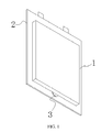
FIG. 1 is an integral structural schematic diagram of an anti-explosion package of a soft-packed secondary battery provided by an embodiment of the present application, in which the anti-explosion area is an inverted trapezoid; -
FIG. 2 is a sectional view ofFIG. 1 ; -
FIG. 3 is an integral structural schematic diagram of the anti-explosion package of the soft-packed secondary battery provided by the embodiments of the present application, in which the anti-explosion area is an inverted circular arc; - 1-
- upper film
- 2-
- lower film
- 3-
- anti-explosion area
31- opening area
311- opening
312- first bottom edge
313- first side wall
32- transition area
321- top edge
322- second bottom edge
323- second side wall
4- packaging area
5- hollow cavity - The drawings are incorporated into the specification and constitute as a part of the specification, showing embodiments of the present application, and are used to explain the theory of the present application together with the specification.
- The present application will be described in further detail through specific embodiments and the accompany drawings. The "front", "back", "left", "right", "up", "down" are referring to the placing state of the anti-explosion package of the soft-packed secondary battery in the drawings.
- As shown in
FIG. 1 andFIG. 2 , the present application provides an anti-explosion package of a soft-packed secondary battery, including: - An
upper film 1, alower film 2, apackaging area 4 and ananti-explosion area 3, an outer edge of theupper film 1 is connected with an outer edge of thelower film 2, the connecting manner can be adhesive connection, thus forming ahollow cavity 5 for accommodating a naked battery core; apackaging area 4 with a certain width is provided on at least one outer edge of theupper film 1 and thelower film 2, inFIG. 2 , all outer edges of the upper film and the lower film are provided withpackaging areas 4. Theanti-explosion area 3 is arranged in thepackaging area 4, thepackaging areas 4 of theupper film 1 and thelower film 2 are all adhered together except the location of the anti-explosion area; theanti-explosion area 3 includes anopening area 31 and a transition area 32, theopening area 31 and the transition area 32 are arranged successively in a direction from an edge of thepackaging area 4 close to thehollow cavity 5 to an edge away from thehollow cavity 5; the portion of theupper film 1 and thelower film 2 located at theopening area 31 is not adhered, the portion of theupper film 1 and thelower film 2 located at the transition area 32 is adhered with an intensity less than that of thepackaging area 4. - It should be noted that: in other embodiments of the present application, the
upper film 1 and thelower film 2 in the embodiment shown inFIG. 1 andFIG. 2 can be arranged as a whole at one outer edge, to form an integral packaging film, the other outer edges of theupper film 1 and thelower film 2 are adhered mutually. Apackaging area 4 with a certain width is provided at the mutually adhered outer edges of the packaging film, that is, folding the integral packaging film in half to form theupper film 1 and thelower film 2, except the outer edge formed by folding, the other outer edges are all provided with thepackaging areas 4. Thus, thepackaging areas 4 of the packaging film are all adhered together except the location of theanti-explosion area 3, which forms thehollow cavity 5 for accommodating the naked battery core. - Due to the existence of the
anti-explosion area 3, thepackaging area 4 will generate a weak area at the location of theanti-explosion area 3. When the battery core of the soft-packed Li-ion battery generates a large amount of heat due to overheating, overcharging, internal short, collision, pressure and so on, at this time, the pressure inside the anti-explosion package increases gradually, when the pressure reaches the pressure limitation of theanti-explosion area 3 of the anti-explosion package of the soft-packed secondary battery, gas and electrolyte can arrive at the weak area of thepackaging area 4 through the guidance of theopening area 31 and the transition area 32, since the width of the weak area is narrower than the other ares of thepackaging area 4, the overall intensity is relatively small, therefore is easy to be broken through by the internal gas with high-pressure and high-temperature, the gas and the electrolyte are ejected from the broken weak area, so as to prevent the continuous increasing of the pressure inside the battery effectively, and prevent the battery from exploding because of the high internal pressure, thereby guaranteeing peoples' life and their property. - Since the
anti-explosion area 3 includes theopening area 31 and the transition area 32 with relative small intensity, when the pressure inside the anti-explosion package increases, the pressure will be gathered at the transition area 32 with relative small intensity first, break through the transition area 32, and then break through thepackaging area 4. However, since the traditional anti-explosion package is not provided with a transition area 32 with relative small intensity, therefore, the high-temperature and high-pressure gas cannot be gathered at theopening 31 and break through thepackaging area 4. - In addition, since the transition area 32 is arranged, the sealing effect of the
opening area 31 can be strengthened, so as to prevent electrolyte leakage of the battery because of the corrosion effect of the electrolyte. - In the embodiment shown in
FIG. 1 andFIG. 2 , theopening area 31 includes anopening 311 connected with thehollow cavity 5, a firstbottom edge 312 connected with the transition area 32 and twofirst side walls 313 connecting theopening 311 and two ends of the firstbottom edge 312; the length of the firstbottom edge 312 is less than that of theopening 311. The twofirst side walls 313 are both bevels, which are arranged symmetrically. - In this way, the pressure due to the heat generated by the battery core can be gathered at the first
bottom edge 312 rapidly, so as to break through the firstbottom edge 312 rapidly. - Of course, the two
first side walls 313 also can be arranged as curved surfaces, in this way, the pressure inside the anti-explosion package can be gathered at the firstbottom edge 312 rapidly, and then break through the firstbottom edge 312 rapidly. - In the embodiment shown in
FIG. 1 andFIG. 2 , the transition area 32 includes atop edge 321 connected with theopening area 31, a secondbottom edge 322 away from theopening area 31 and twosecond side walls 323 connecting thetop edge 321 with two ends of a secondbottom edge 322; the length of the secondbottom edge 322 is less than that of thetop edge 321. The firstbottom edge 312 and thetop edge 321 are overlapped, the extending direction of thesecond side wall 323 is in accordance with that of thefirst side wall 313. - In this way, the bottom edge of the
anti-explosion area 3 can be broken through by the inner high-pressure and high-temperature gas and electrolyte effectively, so as to let the pressure be distributed uniformly and along a single direction, therefore, the weak area can be broke through totally. - In other embodiments of the present application, there can be multiple
anti-explosion areas 3, which are arranged in thepackaging area 4 separately. - In this way, when the pressure in the anti-explosion package is large, multiple
anti-explosion areas 3 can be arranged, the pressure in the anti-explosion package will break through the multipleanti-explosion areas 3, and the gas and the electrolyte are ejected from the brokenanti-explosion area 3. Therefore, multipleanti-explosion areas 3 can facilitate discharging of the gas and electrolyte in the anti-explosion package rapidly. - Preferably, the
anti-explosion area 3 is provided at the middle of thepackaging area 4 located at the outer edge thereof. The energy of the battery core is easy to be released from the middle portion. The length of theanti-explosion area 3 is 1/5-1/10 of the length of thepackaging area 4 located thereof. Arranging like this is because when theanti-explosion area 3 is so large that the leakproofness is poor, which is easy to cause battery leakage; when theanti-explosion area 3 is so small that the weak area cannot be broken through easily by the heat in the battery core, the anti-explosion performance is poor. The size of the transition area 32 in the direction from the side away from theopening area 31 pointing to the opening area 31 (i.e. the size from thetop edge 321 of the transition 32 to the second bottom edge 322) is 1-2 times of the size of theopening area 31 in the same direction. When the width of the transition area 32 is so large that the weak area of thepackaging area 4 cannot be broken through easily by the heat in the battery core, the anti-explosion performance is poor. When the width of the transition area 32 is so small that the leakproofness is poor, which is easy to cause leakage. - The shape of the
anti-explosion area 3 prefers to be inverse trapezoid(refer toFIG. 1 andFIG. 2 ), inverse triangle, inverse circular arc(refer toFIG. 3 ), in this way, the gas is easy to crush into theanti-explosion area 3. - The anti-explosion package of the soft-packed secondary battery according to the present application, on one hand, can prevent the battery explosion effectively, on the other hand, can prevent battery leakage caused by poor leakproofness.
- The above are just the preferred embodiments of the present application, which do not limit the present application, for those skilled in the art, the present application can have various modifications and variations. Any modifications, equivalent replacements and improvements made within the spirit and principle of the present application shall fall into the protect scope of the present application.
Claims (10)
- An anti-explosion package of a soft-packed secondary battery, characterized in that, comprising an upper film, a lower film, a packaging area and an anti-explosion area,
an outer edge of the upper film and an outer edge of the lower film are sealed and connected with each other, so as to form a hollow cavity for accommodating a naked battery core;
wherein, a packaging area with a certain width is provided on at least one outer edge of the upper film and the lower film, the anti-explosion area is arranged in the packaging area, all the packaging areas of the upper film and the lower film are adhered together except the location of the anti-explosion area, so that the upper film and the lower film are sealed at this side,
the anti-explosion area comprises an opening area and a transition area,
the opening area and the transition area are arranged successively in a direction from an edge of the packaging area close to the hollow cavity to an edge away from the hollow cavity;
a portion of the upper film and the lower film located at the opening area is not adhered, a portion of the upper film and the lower film located at the transition area is adhered with an intensity less than that of the packaging area. - The anti-explosion package of the soft-packed secondary battery according to claim 1, characterized in that:the upper film and the lower film are formed by folding an integral structure in half, except the outer edge formed by folding, the other outer edges are all provided with the packaging areas;orall the outer edges of the upper film and the lower film are provided with the packaging areas.
- The anti-explosion package of the soft-packed secondary battery according to claim 1 or 2, characterized in that:the opening area comprises an opening connected with the hollow cavity, a first bottom edge connected with the transition area and two first side walls connecting the opening area and two ends of the first bottom edge;the length of the first bottom edge is less than that of the opening.
- The anti-explosion package of the soft-packed secondary battery according to claim 3, characterized in that:the two first side walls are both curved surfaces or bevels.
- The anti-explosion package of the soft-packed secondary battery according to claim 4, characterized in that:the two first side walls are arranged symmetrically.
- The anti-explosion package of the soft-packed secondary battery according to claim 3, characterized in that:the transition area comprises a top edge connected with the opening area, a second bottom edge away from the opening area and two second side walls connecting the top edge with two ends of the second bottom edge,the length of the second bottom edge is less than that of the top edge.
- The anti-explosion package of the soft-packed secondary battery according to claim 6, characterized in that: the first bottom edge overlaps with the top edge, an extending direction of the second side wall is same as that of the first side wall.
- The anti-explosion package of the soft-packed secondary battery according to claim 1 or 2, characterized in that:there are multiple anti-explosion areas, which are arranged in the packaging area, respectively.
- The anti-explosion package of the soft-packed secondary battery according to claim 1 or 2, characterized in that:the anti-explosion area is located at the middle of the packaging area.
- The anti-explosion package of the soft-packed secondary battery according to claim 1 or 2, characterized in that:the length of the anti-explosion area is 1/5-1/10 of the length of the packaging area; and/orthe size of the transition area in the direction from a side away from the opening area pointing to the opening area is 1-2 times of the size of the opening area in the same direction.
Applications Claiming Priority (1)
| Application Number | Priority Date | Filing Date | Title |
|---|---|---|---|
| CN201620157111.8U CN205406573U (en) | 2016-03-02 | 2016-03-02 | Soft packet of secondary cell casing |
Publications (2)
| Publication Number | Publication Date |
|---|---|
| EP3217448A1 true EP3217448A1 (en) | 2017-09-13 |
| EP3217448B1 EP3217448B1 (en) | 2021-09-29 |
Family
ID=56411496
Family Applications (1)
| Application Number | Title | Priority Date | Filing Date |
|---|---|---|---|
| EP16179345.0A Active EP3217448B1 (en) | 2016-03-02 | 2016-07-13 | Anti-explosion package of soft-packed secondary battery |
Country Status (4)
| Country | Link |
|---|---|
| US (1) | US9911954B2 (en) |
| EP (1) | EP3217448B1 (en) |
| JP (1) | JP2017157545A (en) |
| CN (1) | CN205406573U (en) |
Families Citing this family (10)
| Publication number | Priority date | Publication date | Assignee | Title |
|---|---|---|---|---|
| CN110504392A (en) * | 2018-05-18 | 2019-11-26 | 宁德新能源科技有限公司 | Battery |
| CN112133851A (en) * | 2019-06-25 | 2020-12-25 | 比亚迪股份有限公司 | Battery pack and vehicle with same |
| CN111697168B (en) * | 2020-06-17 | 2023-02-10 | 惠州亿纬锂能股份有限公司 | Lithium battery and cap |
| CN111697169B (en) * | 2020-06-17 | 2023-05-09 | 惠州亿纬锂能股份有限公司 | Lithium battery and cap |
| CN116349064B (en) * | 2020-10-06 | 2024-06-18 | 株式会社Lg新能源 | Soft-pack battery case, molding apparatus thereof, and soft-pack secondary battery |
| DE102020216383A1 (en) * | 2020-12-21 | 2022-06-23 | Volkswagen Aktiengesellschaft | battery cell module and battery |
| CN113921983A (en) * | 2021-09-28 | 2022-01-11 | 浙江锋锂新能源科技有限公司 | A battery module with a directional pressure relief structure |
| CN114865215A (en) * | 2022-04-29 | 2022-08-05 | 远景动力技术(江苏)有限公司 | Laminate polymer battery and electronic equipment with directional blasting function |
| CN114899470B (en) * | 2022-05-13 | 2025-11-04 | 齐鲁中科光物理与工程技术研究院 | A high-safety soft-pack battery and its preparation method |
| CN220627729U (en) | 2022-06-27 | 2024-03-19 | 米沃奇电动工具公司 | Fuses and devices including conductive paths for the passage of electric current |
Citations (6)
| Publication number | Priority date | Publication date | Assignee | Title |
|---|---|---|---|---|
| JPH1055792A (en) * | 1996-08-12 | 1998-02-24 | Yuasa Corp | Thin battery |
| JP2005222872A (en) * | 2004-02-09 | 2005-08-18 | Toyota Motor Corp | Laminated battery |
| US20110104527A1 (en) * | 2007-12-14 | 2011-05-05 | Lg Chem, Ltd. | Secondary battery having sealing portion of novel structure |
| US20110223448A1 (en) * | 2010-03-11 | 2011-09-15 | Jun-Sik Kim | Rechargeable battery |
| KR20120060314A (en) * | 2010-12-02 | 2012-06-12 | 주식회사 엘지화학 | Secondary Battery Having Sealing Portion of Novel Structure |
| KR20140055641A (en) * | 2012-11-01 | 2014-05-09 | 현대모비스 주식회사 | Secondary battery |
Family Cites Families (7)
| Publication number | Priority date | Publication date | Assignee | Title |
|---|---|---|---|---|
| US4842965A (en) * | 1986-09-27 | 1989-06-27 | Hitachi Maxell, Ltd. | Non aqueous electrochemical battery with explosion proof arrangement and a method of the production thereof |
| JP2000100399A (en) * | 1998-09-21 | 2000-04-07 | Toshiba Battery Co Ltd | Method for producing polymer lithium secondary battery |
| JP4232038B2 (en) * | 2004-08-11 | 2009-03-04 | 日本電気株式会社 | Film-clad electrical device and method for manufacturing the same |
| JP2009187889A (en) * | 2008-02-08 | 2009-08-20 | Nissan Motor Co Ltd | Battery case and battery pack |
| JP5129280B2 (en) * | 2010-02-26 | 2013-01-30 | 日立ビークルエナジー株式会社 | Secondary battery |
| US9118061B2 (en) * | 2010-08-13 | 2015-08-25 | Samsung Sdi Co., Ltd. | Secondary battery |
| KR101547403B1 (en) * | 2013-01-11 | 2015-08-25 | 주식회사 엘지화학 | Secondary battery comprising unified positive lead and negative lead and the method for preparing thereof |
-
2016
- 2016-03-02 CN CN201620157111.8U patent/CN205406573U/en not_active Expired - Lifetime
- 2016-07-11 JP JP2016136766A patent/JP2017157545A/en active Pending
- 2016-07-13 EP EP16179345.0A patent/EP3217448B1/en active Active
- 2016-09-06 US US15/257,503 patent/US9911954B2/en active Active
Patent Citations (6)
| Publication number | Priority date | Publication date | Assignee | Title |
|---|---|---|---|---|
| JPH1055792A (en) * | 1996-08-12 | 1998-02-24 | Yuasa Corp | Thin battery |
| JP2005222872A (en) * | 2004-02-09 | 2005-08-18 | Toyota Motor Corp | Laminated battery |
| US20110104527A1 (en) * | 2007-12-14 | 2011-05-05 | Lg Chem, Ltd. | Secondary battery having sealing portion of novel structure |
| US20110223448A1 (en) * | 2010-03-11 | 2011-09-15 | Jun-Sik Kim | Rechargeable battery |
| KR20120060314A (en) * | 2010-12-02 | 2012-06-12 | 주식회사 엘지화학 | Secondary Battery Having Sealing Portion of Novel Structure |
| KR20140055641A (en) * | 2012-11-01 | 2014-05-09 | 현대모비스 주식회사 | Secondary battery |
Also Published As
| Publication number | Publication date |
|---|---|
| US9911954B2 (en) | 2018-03-06 |
| JP2017157545A (en) | 2017-09-07 |
| EP3217448B1 (en) | 2021-09-29 |
| US20170256765A1 (en) | 2017-09-07 |
| CN205406573U (en) | 2016-07-27 |
Similar Documents
| Publication | Publication Date | Title |
|---|---|---|
| US9911954B2 (en) | Anti-explosion package of soft-packed secondary battery | |
| US20230113132A1 (en) | Explosion-proof sheet, top cover assembly of secondary battery, and secondary battery | |
| JP5461610B2 (en) | Battery and battery system | |
| US20190245175A1 (en) | Battery module | |
| US10283753B2 (en) | Cell and electrochemical device | |
| EP3734685B1 (en) | Battery | |
| JP6479345B2 (en) | Secondary battery and secondary battery pack including the same | |
| KR102522705B1 (en) | Secondary Battery | |
| JP3244519U (en) | Battery cover for cylindrical batteries and cylindrical batteries | |
| JP2015526858A (en) | Pouch-type secondary battery with safety vent | |
| CN109920963B (en) | Battery cover assembly, single battery, battery module, power battery and electric vehicle | |
| CN218731600U (en) | Explosion-proof valve, battery cover plate and battery | |
| CN116557596A (en) | Explosion-proof valves, end cap assemblies, batteries and energy storage devices | |
| KR102195733B1 (en) | Curved secondary battery | |
| CN220914389U (en) | Battery cell cover plate, battery cell and battery pack | |
| JP2021517726A (en) | Battery cell and lithium-ion battery | |
| KR100824878B1 (en) | Secondary battery | |
| KR102921543B1 (en) | Electrode assembly and secondary battery comprising the same | |
| KR20240083794A (en) | battery module and battery pack including the same | |
| KR102192993B1 (en) | Pouch for secondary battery and secondary battery having the same | |
| JP2017162570A (en) | Power storage element | |
| CN107615511A (en) | A kind of battery | |
| EP3490036A1 (en) | Secondary battery and method for manufacturing such secondary battery | |
| CN203850387U (en) | Soft-packaged lithium ion secondary battery | |
| KR102823838B1 (en) | Pouch-type secondary battery |
Legal Events
| Date | Code | Title | Description |
|---|---|---|---|
| PUAI | Public reference made under article 153(3) epc to a published international application that has entered the european phase |
Free format text: ORIGINAL CODE: 0009012 |
|
| STAA | Information on the status of an ep patent application or granted ep patent |
Free format text: STATUS: REQUEST FOR EXAMINATION WAS MADE |
|
| 17P | Request for examination filed |
Effective date: 20160713 |
|
| AK | Designated contracting states |
Kind code of ref document: A1 Designated state(s): AL AT BE BG CH CY CZ DE DK EE ES FI FR GB GR HR HU IE IS IT LI LT LU LV MC MK MT NL NO PL PT RO RS SE SI SK SM TR |
|
| AX | Request for extension of the european patent |
Extension state: BA ME |
|
| RBV | Designated contracting states (corrected) |
Designated state(s): AL AT BE BG CH CY CZ DE DK EE ES FI FR GB GR HR HU IE IS IT LI LT LU LV MC MK MT NL NO PL PT RO RS SE SI SK SM TR |
|
| STAA | Information on the status of an ep patent application or granted ep patent |
Free format text: STATUS: EXAMINATION IS IN PROGRESS |
|
| 17Q | First examination report despatched |
Effective date: 20190627 |
|
| REG | Reference to a national code |
Ref country code: DE Ref legal event code: R079 Ref document number: 602016064241 Country of ref document: DE Free format text: PREVIOUS MAIN CLASS: H01M0002020000 Ipc: H01M0050103000 |
|
| GRAP | Despatch of communication of intention to grant a patent |
Free format text: ORIGINAL CODE: EPIDOSNIGR1 |
|
| STAA | Information on the status of an ep patent application or granted ep patent |
Free format text: STATUS: GRANT OF PATENT IS INTENDED |
|
| RIC1 | Information provided on ipc code assigned before grant |
Ipc: H01M 50/557 20210101ALI20210421BHEP Ipc: H01M 50/543 20210101ALI20210421BHEP Ipc: H01M 50/342 20210101ALI20210421BHEP Ipc: H01M 50/124 20210101ALI20210421BHEP Ipc: H01M 50/103 20210101AFI20210421BHEP |
|
| INTG | Intention to grant announced |
Effective date: 20210526 |
|
| GRAS | Grant fee paid |
Free format text: ORIGINAL CODE: EPIDOSNIGR3 |
|
| GRAA | (expected) grant |
Free format text: ORIGINAL CODE: 0009210 |
|
| STAA | Information on the status of an ep patent application or granted ep patent |
Free format text: STATUS: THE PATENT HAS BEEN GRANTED |
|
| AK | Designated contracting states |
Kind code of ref document: B1 Designated state(s): AL AT BE BG CH CY CZ DE DK EE ES FI FR GB GR HR HU IE IS IT LI LT LU LV MC MK MT NL NO PL PT RO RS SE SI SK SM TR |
|
| REG | Reference to a national code |
Ref country code: GB Ref legal event code: FG4D |
|
| REG | Reference to a national code |
Ref country code: DE Ref legal event code: R096 Ref document number: 602016064241 Country of ref document: DE |
|
| REG | Reference to a national code |
Ref country code: CH Ref legal event code: EP Ref country code: AT Ref legal event code: REF Ref document number: 1434995 Country of ref document: AT Kind code of ref document: T Effective date: 20211015 |
|
| REG | Reference to a national code |
Ref country code: IE Ref legal event code: FG4D |
|
| REG | Reference to a national code |
Ref country code: LT Ref legal event code: MG9D |
|
| PG25 | Lapsed in a contracting state [announced via postgrant information from national office to epo] |
Ref country code: FI Free format text: LAPSE BECAUSE OF FAILURE TO SUBMIT A TRANSLATION OF THE DESCRIPTION OR TO PAY THE FEE WITHIN THE PRESCRIBED TIME-LIMIT Effective date: 20210929 Ref country code: NO Free format text: LAPSE BECAUSE OF FAILURE TO SUBMIT A TRANSLATION OF THE DESCRIPTION OR TO PAY THE FEE WITHIN THE PRESCRIBED TIME-LIMIT Effective date: 20211229 Ref country code: LT Free format text: LAPSE BECAUSE OF FAILURE TO SUBMIT A TRANSLATION OF THE DESCRIPTION OR TO PAY THE FEE WITHIN THE PRESCRIBED TIME-LIMIT Effective date: 20210929 Ref country code: BG Free format text: LAPSE BECAUSE OF FAILURE TO SUBMIT A TRANSLATION OF THE DESCRIPTION OR TO PAY THE FEE WITHIN THE PRESCRIBED TIME-LIMIT Effective date: 20211229 Ref country code: SE Free format text: LAPSE BECAUSE OF FAILURE TO SUBMIT A TRANSLATION OF THE DESCRIPTION OR TO PAY THE FEE WITHIN THE PRESCRIBED TIME-LIMIT Effective date: 20210929 Ref country code: RS Free format text: LAPSE BECAUSE OF FAILURE TO SUBMIT A TRANSLATION OF THE DESCRIPTION OR TO PAY THE FEE WITHIN THE PRESCRIBED TIME-LIMIT Effective date: 20210929 Ref country code: HR Free format text: LAPSE BECAUSE OF FAILURE TO SUBMIT A TRANSLATION OF THE DESCRIPTION OR TO PAY THE FEE WITHIN THE PRESCRIBED TIME-LIMIT Effective date: 20210929 |
|
| REG | Reference to a national code |
Ref country code: NL Ref legal event code: MP Effective date: 20210929 |
|
| REG | Reference to a national code |
Ref country code: AT Ref legal event code: MK05 Ref document number: 1434995 Country of ref document: AT Kind code of ref document: T Effective date: 20210929 |
|
| PG25 | Lapsed in a contracting state [announced via postgrant information from national office to epo] |
Ref country code: LV Free format text: LAPSE BECAUSE OF FAILURE TO SUBMIT A TRANSLATION OF THE DESCRIPTION OR TO PAY THE FEE WITHIN THE PRESCRIBED TIME-LIMIT Effective date: 20210929 Ref country code: GR Free format text: LAPSE BECAUSE OF FAILURE TO SUBMIT A TRANSLATION OF THE DESCRIPTION OR TO PAY THE FEE WITHIN THE PRESCRIBED TIME-LIMIT Effective date: 20211230 |
|
| PG25 | Lapsed in a contracting state [announced via postgrant information from national office to epo] |
Ref country code: AT Free format text: LAPSE BECAUSE OF FAILURE TO SUBMIT A TRANSLATION OF THE DESCRIPTION OR TO PAY THE FEE WITHIN THE PRESCRIBED TIME-LIMIT Effective date: 20210929 |
|
| PG25 | Lapsed in a contracting state [announced via postgrant information from national office to epo] |
Ref country code: IS Free format text: LAPSE BECAUSE OF FAILURE TO SUBMIT A TRANSLATION OF THE DESCRIPTION OR TO PAY THE FEE WITHIN THE PRESCRIBED TIME-LIMIT Effective date: 20220129 Ref country code: SK Free format text: LAPSE BECAUSE OF FAILURE TO SUBMIT A TRANSLATION OF THE DESCRIPTION OR TO PAY THE FEE WITHIN THE PRESCRIBED TIME-LIMIT Effective date: 20210929 Ref country code: RO Free format text: LAPSE BECAUSE OF FAILURE TO SUBMIT A TRANSLATION OF THE DESCRIPTION OR TO PAY THE FEE WITHIN THE PRESCRIBED TIME-LIMIT Effective date: 20210929 Ref country code: PT Free format text: LAPSE BECAUSE OF FAILURE TO SUBMIT A TRANSLATION OF THE DESCRIPTION OR TO PAY THE FEE WITHIN THE PRESCRIBED TIME-LIMIT Effective date: 20220131 Ref country code: PL Free format text: LAPSE BECAUSE OF FAILURE TO SUBMIT A TRANSLATION OF THE DESCRIPTION OR TO PAY THE FEE WITHIN THE PRESCRIBED TIME-LIMIT Effective date: 20210929 Ref country code: NL Free format text: LAPSE BECAUSE OF FAILURE TO SUBMIT A TRANSLATION OF THE DESCRIPTION OR TO PAY THE FEE WITHIN THE PRESCRIBED TIME-LIMIT Effective date: 20210929 Ref country code: ES Free format text: LAPSE BECAUSE OF FAILURE TO SUBMIT A TRANSLATION OF THE DESCRIPTION OR TO PAY THE FEE WITHIN THE PRESCRIBED TIME-LIMIT Effective date: 20210929 Ref country code: EE Free format text: LAPSE BECAUSE OF FAILURE TO SUBMIT A TRANSLATION OF THE DESCRIPTION OR TO PAY THE FEE WITHIN THE PRESCRIBED TIME-LIMIT Effective date: 20210929 Ref country code: CZ Free format text: LAPSE BECAUSE OF FAILURE TO SUBMIT A TRANSLATION OF THE DESCRIPTION OR TO PAY THE FEE WITHIN THE PRESCRIBED TIME-LIMIT Effective date: 20210929 Ref country code: AL Free format text: LAPSE BECAUSE OF FAILURE TO SUBMIT A TRANSLATION OF THE DESCRIPTION OR TO PAY THE FEE WITHIN THE PRESCRIBED TIME-LIMIT Effective date: 20210929 |
|
| REG | Reference to a national code |
Ref country code: DE Ref legal event code: R097 Ref document number: 602016064241 Country of ref document: DE |
|
| PG25 | Lapsed in a contracting state [announced via postgrant information from national office to epo] |
Ref country code: DK Free format text: LAPSE BECAUSE OF FAILURE TO SUBMIT A TRANSLATION OF THE DESCRIPTION OR TO PAY THE FEE WITHIN THE PRESCRIBED TIME-LIMIT Effective date: 20210929 |
|
| PLBE | No opposition filed within time limit |
Free format text: ORIGINAL CODE: 0009261 |
|
| STAA | Information on the status of an ep patent application or granted ep patent |
Free format text: STATUS: NO OPPOSITION FILED WITHIN TIME LIMIT |
|
| 26N | No opposition filed |
Effective date: 20220630 |
|
| PG25 | Lapsed in a contracting state [announced via postgrant information from national office to epo] |
Ref country code: SI Free format text: LAPSE BECAUSE OF FAILURE TO SUBMIT A TRANSLATION OF THE DESCRIPTION OR TO PAY THE FEE WITHIN THE PRESCRIBED TIME-LIMIT Effective date: 20210929 |
|
| PG25 | Lapsed in a contracting state [announced via postgrant information from national office to epo] |
Ref country code: IT Free format text: LAPSE BECAUSE OF FAILURE TO SUBMIT A TRANSLATION OF THE DESCRIPTION OR TO PAY THE FEE WITHIN THE PRESCRIBED TIME-LIMIT Effective date: 20210929 |
|
| PG25 | Lapsed in a contracting state [announced via postgrant information from national office to epo] |
Ref country code: MC Free format text: LAPSE BECAUSE OF FAILURE TO SUBMIT A TRANSLATION OF THE DESCRIPTION OR TO PAY THE FEE WITHIN THE PRESCRIBED TIME-LIMIT Effective date: 20210929 |
|
| REG | Reference to a national code |
Ref country code: CH Ref legal event code: PL |
|
| REG | Reference to a national code |
Ref country code: BE Ref legal event code: MM Effective date: 20220731 |
|
| PG25 | Lapsed in a contracting state [announced via postgrant information from national office to epo] |
Ref country code: LU Free format text: LAPSE BECAUSE OF NON-PAYMENT OF DUE FEES Effective date: 20220713 Ref country code: LI Free format text: LAPSE BECAUSE OF NON-PAYMENT OF DUE FEES Effective date: 20220731 Ref country code: CH Free format text: LAPSE BECAUSE OF NON-PAYMENT OF DUE FEES Effective date: 20220731 |
|
| PG25 | Lapsed in a contracting state [announced via postgrant information from national office to epo] |
Ref country code: BE Free format text: LAPSE BECAUSE OF NON-PAYMENT OF DUE FEES Effective date: 20220731 |
|
| P01 | Opt-out of the competence of the unified patent court (upc) registered |
Effective date: 20230516 |
|
| PG25 | Lapsed in a contracting state [announced via postgrant information from national office to epo] |
Ref country code: IE Free format text: LAPSE BECAUSE OF NON-PAYMENT OF DUE FEES Effective date: 20220713 |
|
| PG25 | Lapsed in a contracting state [announced via postgrant information from national office to epo] |
Ref country code: HU Free format text: LAPSE BECAUSE OF FAILURE TO SUBMIT A TRANSLATION OF THE DESCRIPTION OR TO PAY THE FEE WITHIN THE PRESCRIBED TIME-LIMIT; INVALID AB INITIO Effective date: 20160713 |
|
| PG25 | Lapsed in a contracting state [announced via postgrant information from national office to epo] |
Ref country code: SM Free format text: LAPSE BECAUSE OF FAILURE TO SUBMIT A TRANSLATION OF THE DESCRIPTION OR TO PAY THE FEE WITHIN THE PRESCRIBED TIME-LIMIT Effective date: 20210929 Ref country code: MK Free format text: LAPSE BECAUSE OF FAILURE TO SUBMIT A TRANSLATION OF THE DESCRIPTION OR TO PAY THE FEE WITHIN THE PRESCRIBED TIME-LIMIT Effective date: 20210929 Ref country code: CY Free format text: LAPSE BECAUSE OF FAILURE TO SUBMIT A TRANSLATION OF THE DESCRIPTION OR TO PAY THE FEE WITHIN THE PRESCRIBED TIME-LIMIT Effective date: 20210929 |
|
| REG | Reference to a national code |
Ref country code: DE Ref legal event code: R081 Ref document number: 602016064241 Country of ref document: DE Owner name: CONTEMPORARY AMPEREX TECHNOLOGY (HONG KONG) LT, HK Free format text: FORMER OWNER: CONTEMPORARY AMPEREX TECHNOLOGY CO., LIMITED, NINGDE CITY, FUJIAN, CN |
|
| REG | Reference to a national code |
Ref country code: GB Ref legal event code: 732E Free format text: REGISTERED BETWEEN 20240801 AND 20240807 |
|
| PG25 | Lapsed in a contracting state [announced via postgrant information from national office to epo] |
Ref country code: MT Free format text: LAPSE BECAUSE OF FAILURE TO SUBMIT A TRANSLATION OF THE DESCRIPTION OR TO PAY THE FEE WITHIN THE PRESCRIBED TIME-LIMIT Effective date: 20210929 |
|
| PGFP | Annual fee paid to national office [announced via postgrant information from national office to epo] |
Ref country code: GB Payment date: 20250522 Year of fee payment: 10 |
|
| PGFP | Annual fee paid to national office [announced via postgrant information from national office to epo] |
Ref country code: FR Payment date: 20250508 Year of fee payment: 10 |
|
| PGFP | Annual fee paid to national office [announced via postgrant information from national office to epo] |
Ref country code: DE Payment date: 20250521 Year of fee payment: 10 |
|
| PG25 | Lapsed in a contracting state [announced via postgrant information from national office to epo] |
Ref country code: TR Free format text: LAPSE BECAUSE OF FAILURE TO SUBMIT A TRANSLATION OF THE DESCRIPTION OR TO PAY THE FEE WITHIN THE PRESCRIBED TIME-LIMIT Effective date: 20210929 |