EP3217384B1 - Head mounted display and information processing method - Google Patents
Head mounted display and information processing method Download PDFInfo
- Publication number
- EP3217384B1 EP3217384B1 EP15856535.8A EP15856535A EP3217384B1 EP 3217384 B1 EP3217384 B1 EP 3217384B1 EP 15856535 A EP15856535 A EP 15856535A EP 3217384 B1 EP3217384 B1 EP 3217384B1
- Authority
- EP
- European Patent Office
- Prior art keywords
- head
- mounted display
- user
- section
- still object
- Prior art date
- Legal status (The legal status is an assumption and is not a legal conclusion. Google has not performed a legal analysis and makes no representation as to the accuracy of the status listed.)
- Active
Links
- 230000010365 information processing Effects 0.000 title claims description 7
- 238000003672 processing method Methods 0.000 title claims description 4
- 238000005259 measurement Methods 0.000 claims description 61
- 238000001514 detection method Methods 0.000 claims description 22
- 238000000034 method Methods 0.000 claims description 11
- 230000000903 blocking effect Effects 0.000 claims description 4
- 238000010586 diagram Methods 0.000 description 6
- 238000005516 engineering process Methods 0.000 description 5
- 230000000694 effects Effects 0.000 description 4
- 230000008569 process Effects 0.000 description 4
- 230000009471 action Effects 0.000 description 3
- 230000001133 acceleration Effects 0.000 description 2
- 238000004458 analytical method Methods 0.000 description 2
- 230000008859 change Effects 0.000 description 2
- 238000005401 electroluminescence Methods 0.000 description 2
- 210000003128 head Anatomy 0.000 description 2
- 238000007654 immersion Methods 0.000 description 2
- 238000012986 modification Methods 0.000 description 2
- 230000004048 modification Effects 0.000 description 2
- 238000012545 processing Methods 0.000 description 2
- 230000005855 radiation Effects 0.000 description 2
- 230000003213 activating effect Effects 0.000 description 1
- 230000003466 anti-cipated effect Effects 0.000 description 1
- 210000005252 bulbus oculi Anatomy 0.000 description 1
- 238000004364 calculation method Methods 0.000 description 1
- 238000006243 chemical reaction Methods 0.000 description 1
- 238000004891 communication Methods 0.000 description 1
- 238000004590 computer program Methods 0.000 description 1
- 238000011161 development Methods 0.000 description 1
- 230000018109 developmental process Effects 0.000 description 1
- 230000002708 enhancing effect Effects 0.000 description 1
- 238000000605 extraction Methods 0.000 description 1
- 230000006870 function Effects 0.000 description 1
- 230000014509 gene expression Effects 0.000 description 1
- 238000010191 image analysis Methods 0.000 description 1
- 230000010354 integration Effects 0.000 description 1
- 239000004973 liquid crystal related substance Substances 0.000 description 1
- 239000004065 semiconductor Substances 0.000 description 1
- 230000001960 triggered effect Effects 0.000 description 1
Images
Classifications
-
- G—PHYSICS
- G06—COMPUTING; CALCULATING OR COUNTING
- G06F—ELECTRIC DIGITAL DATA PROCESSING
- G06F3/00—Input arrangements for transferring data to be processed into a form capable of being handled by the computer; Output arrangements for transferring data from processing unit to output unit, e.g. interface arrangements
- G06F3/14—Digital output to display device ; Cooperation and interconnection of the display device with other functional units
- G06F3/147—Digital output to display device ; Cooperation and interconnection of the display device with other functional units using display panels
-
- G—PHYSICS
- G02—OPTICS
- G02B—OPTICAL ELEMENTS, SYSTEMS OR APPARATUS
- G02B27/00—Optical systems or apparatus not provided for by any of the groups G02B1/00 - G02B26/00, G02B30/00
- G02B27/01—Head-up displays
- G02B27/0101—Head-up displays characterised by optical features
-
- G—PHYSICS
- G02—OPTICS
- G02B—OPTICAL ELEMENTS, SYSTEMS OR APPARATUS
- G02B27/00—Optical systems or apparatus not provided for by any of the groups G02B1/00 - G02B26/00, G02B30/00
- G02B27/01—Head-up displays
- G02B27/017—Head mounted
-
- G—PHYSICS
- G02—OPTICS
- G02B—OPTICAL ELEMENTS, SYSTEMS OR APPARATUS
- G02B27/00—Optical systems or apparatus not provided for by any of the groups G02B1/00 - G02B26/00, G02B30/00
- G02B27/01—Head-up displays
- G02B27/017—Head mounted
- G02B27/0172—Head mounted characterised by optical features
-
- G—PHYSICS
- G06—COMPUTING; CALCULATING OR COUNTING
- G06F—ELECTRIC DIGITAL DATA PROCESSING
- G06F3/00—Input arrangements for transferring data to be processed into a form capable of being handled by the computer; Output arrangements for transferring data from processing unit to output unit, e.g. interface arrangements
- G06F3/01—Input arrangements or combined input and output arrangements for interaction between user and computer
- G06F3/011—Arrangements for interaction with the human body, e.g. for user immersion in virtual reality
-
- G—PHYSICS
- G06—COMPUTING; CALCULATING OR COUNTING
- G06F—ELECTRIC DIGITAL DATA PROCESSING
- G06F3/00—Input arrangements for transferring data to be processed into a form capable of being handled by the computer; Output arrangements for transferring data from processing unit to output unit, e.g. interface arrangements
- G06F3/01—Input arrangements or combined input and output arrangements for interaction between user and computer
- G06F3/03—Arrangements for converting the position or the displacement of a member into a coded form
- G06F3/033—Pointing devices displaced or positioned by the user, e.g. mice, trackballs, pens or joysticks; Accessories therefor
- G06F3/0346—Pointing devices displaced or positioned by the user, e.g. mice, trackballs, pens or joysticks; Accessories therefor with detection of the device orientation or free movement in a 3D space, e.g. 3D mice, 6-DOF [six degrees of freedom] pointers using gyroscopes, accelerometers or tilt-sensors
-
- G—PHYSICS
- G08—SIGNALLING
- G08B—SIGNALLING OR CALLING SYSTEMS; ORDER TELEGRAPHS; ALARM SYSTEMS
- G08B21/00—Alarms responsive to a single specified undesired or abnormal condition and not otherwise provided for
- G08B21/02—Alarms for ensuring the safety of persons
-
- G—PHYSICS
- G09—EDUCATION; CRYPTOGRAPHY; DISPLAY; ADVERTISING; SEALS
- G09G—ARRANGEMENTS OR CIRCUITS FOR CONTROL OF INDICATING DEVICES USING STATIC MEANS TO PRESENT VARIABLE INFORMATION
- G09G3/00—Control arrangements or circuits, of interest only in connection with visual indicators other than cathode-ray tubes
- G09G3/001—Control arrangements or circuits, of interest only in connection with visual indicators other than cathode-ray tubes using specific devices not provided for in groups G09G3/02 - G09G3/36, e.g. using an intermediate record carrier such as a film slide; Projection systems; Display of non-alphanumerical information, solely or in combination with alphanumerical information, e.g. digital display on projected diapositive as background
- G09G3/002—Control arrangements or circuits, of interest only in connection with visual indicators other than cathode-ray tubes using specific devices not provided for in groups G09G3/02 - G09G3/36, e.g. using an intermediate record carrier such as a film slide; Projection systems; Display of non-alphanumerical information, solely or in combination with alphanumerical information, e.g. digital display on projected diapositive as background to project the image of a two-dimensional display, such as an array of light emitting or modulating elements or a CRT
-
- G—PHYSICS
- G09—EDUCATION; CRYPTOGRAPHY; DISPLAY; ADVERTISING; SEALS
- G09G—ARRANGEMENTS OR CIRCUITS FOR CONTROL OF INDICATING DEVICES USING STATIC MEANS TO PRESENT VARIABLE INFORMATION
- G09G3/00—Control arrangements or circuits, of interest only in connection with visual indicators other than cathode-ray tubes
- G09G3/20—Control arrangements or circuits, of interest only in connection with visual indicators other than cathode-ray tubes for presentation of an assembly of a number of characters, e.g. a page, by composing the assembly by combination of individual elements arranged in a matrix no fixed position being assigned to or needed to be assigned to the individual characters or partial characters
-
- G—PHYSICS
- G09—EDUCATION; CRYPTOGRAPHY; DISPLAY; ADVERTISING; SEALS
- G09G—ARRANGEMENTS OR CIRCUITS FOR CONTROL OF INDICATING DEVICES USING STATIC MEANS TO PRESENT VARIABLE INFORMATION
- G09G5/00—Control arrangements or circuits for visual indicators common to cathode-ray tube indicators and other visual indicators
- G09G5/36—Control arrangements or circuits for visual indicators common to cathode-ray tube indicators and other visual indicators characterised by the display of a graphic pattern, e.g. using an all-points-addressable [APA] memory
- G09G5/37—Details of the operation on graphic patterns
- G09G5/377—Details of the operation on graphic patterns for mixing or overlaying two or more graphic patterns
-
- G—PHYSICS
- G02—OPTICS
- G02B—OPTICAL ELEMENTS, SYSTEMS OR APPARATUS
- G02B27/00—Optical systems or apparatus not provided for by any of the groups G02B1/00 - G02B26/00, G02B30/00
- G02B27/01—Head-up displays
- G02B27/0101—Head-up displays characterised by optical features
- G02B2027/0138—Head-up displays characterised by optical features comprising image capture systems, e.g. camera
-
- G—PHYSICS
- G02—OPTICS
- G02B—OPTICAL ELEMENTS, SYSTEMS OR APPARATUS
- G02B27/00—Optical systems or apparatus not provided for by any of the groups G02B1/00 - G02B26/00, G02B30/00
- G02B27/01—Head-up displays
- G02B27/0101—Head-up displays characterised by optical features
- G02B2027/014—Head-up displays characterised by optical features comprising information/image processing systems
-
- G—PHYSICS
- G02—OPTICS
- G02B—OPTICAL ELEMENTS, SYSTEMS OR APPARATUS
- G02B27/00—Optical systems or apparatus not provided for by any of the groups G02B1/00 - G02B26/00, G02B30/00
- G02B27/01—Head-up displays
- G02B27/0101—Head-up displays characterised by optical features
- G02B2027/0141—Head-up displays characterised by optical features characterised by the informative content of the display
-
- G—PHYSICS
- G02—OPTICS
- G02B—OPTICAL ELEMENTS, SYSTEMS OR APPARATUS
- G02B27/00—Optical systems or apparatus not provided for by any of the groups G02B1/00 - G02B26/00, G02B30/00
- G02B27/01—Head-up displays
- G02B27/0149—Head-up displays characterised by mechanical features
- G02B2027/0167—Emergency system, e.g. to prevent injuries
-
- G—PHYSICS
- G02—OPTICS
- G02B—OPTICAL ELEMENTS, SYSTEMS OR APPARATUS
- G02B27/00—Optical systems or apparatus not provided for by any of the groups G02B1/00 - G02B26/00, G02B30/00
- G02B27/01—Head-up displays
- G02B27/0179—Display position adjusting means not related to the information to be displayed
- G02B2027/0187—Display position adjusting means not related to the information to be displayed slaved to motion of at least a part of the body of the user, e.g. head, eye
-
- G—PHYSICS
- G02—OPTICS
- G02B—OPTICAL ELEMENTS, SYSTEMS OR APPARATUS
- G02B27/00—Optical systems or apparatus not provided for by any of the groups G02B1/00 - G02B26/00, G02B30/00
- G02B27/01—Head-up displays
- G02B2027/0192—Supplementary details
-
- G—PHYSICS
- G09—EDUCATION; CRYPTOGRAPHY; DISPLAY; ADVERTISING; SEALS
- G09G—ARRANGEMENTS OR CIRCUITS FOR CONTROL OF INDICATING DEVICES USING STATIC MEANS TO PRESENT VARIABLE INFORMATION
- G09G2370/00—Aspects of data communication
- G09G2370/16—Use of wireless transmission of display information
-
- H—ELECTRICITY
- H04—ELECTRIC COMMUNICATION TECHNIQUE
- H04N—PICTORIAL COMMUNICATION, e.g. TELEVISION
- H04N13/00—Stereoscopic video systems; Multi-view video systems; Details thereof
- H04N13/20—Image signal generators
- H04N13/204—Image signal generators using stereoscopic image cameras
- H04N13/239—Image signal generators using stereoscopic image cameras using two 2D image sensors having a relative position equal to or related to the interocular distance
-
- H—ELECTRICITY
- H04—ELECTRIC COMMUNICATION TECHNIQUE
- H04N—PICTORIAL COMMUNICATION, e.g. TELEVISION
- H04N5/00—Details of television systems
- H04N5/64—Constructional details of receivers, e.g. cabinets or dust covers
Definitions
- the present invention relates to a head-mounted display and an information processing method carried out by the head-mounted display.
- WO 2013/952855 A2 relates to detecting physical objects near a substantially transparent head-mounted display system and activating a collision-avoidance action to alert a user of the detected objects.
- Detection techniques may include receiving data from distance and/or relative movement sensors and using this data as a basis for determining an appropriate collision-avoidance action.
- Exemplary collision-avoidance actions may include de-emphasizing virtual objects displayed on the HMD to provide a less cluttered view of the physical objects through the substantially transparent display and/or presenting new virtual objects.
- a head-mounted display is worn in such a manner as to cover both eyeballs of the user, an observer.
- Some head-mounted displays are non-see-through ones. Each of these head-mounted displays blocks out an outside world from a user's vision and presents a video when worn by the user. In general, when wearing such a non-see-through head-mounted display, the user has difficulty in viewing a real-world scene in the outside world.
- a non-see-through head-mounted display where the user is allowed to move or play to a limited extent such as at home, it is convenient to present, to the user, the extent to which the user wearing the head-mounted display is allowed to move.
- the present invention has been devised in light of the foregoing, and it is an object of the present invention to provide a technology for notifying an outside world condition to a user wearing a non-see-through head-mounted display.
- a head-mounted display blocks out an outside world from a user's vision and presents a video when worn by the user.
- the head-mounted display includes an outside world measurement section, a notification information detection section, and a notification section.
- the outside world measurement section measures outside world information.
- the notification information detection section detects whether or not the information measured by the outside world measurement section contains any notification information to be notified to the user.
- the notification section notifies the user when the notification information detection section detects notification information.
- Another mode of the present invention is an information processing method carried out by a processor of a head-mounted display for blocking out an outside world from a user's vision when worn by the user to present a video.
- This method includes a step of measuring outside world information.
- This method includes another step of detecting whether or not the measured information contains any notification information to be notified to the user.
- This method includes still another step of notifying the user when notification information is detected.
- Still another mode of the present invention is a program for causing a computer to perform the steps of the above method.
- This program may be supplied as part of firmware built into an apparatus to basically control hardware resources such as video, audio, game apparatus, and head-mounted display.
- This firmware is stored in a semiconductor memory such as read only memory (ROM) or flash memory in the apparatus.
- ROM read only memory
- flash memory in the apparatus.
- a computer-readable recording medium recording this program may be supplied or transmitted via a communication line.
- the present invention provides a technology for notifying an outside world condition to a user wearing a non-see-through head-mounted display.
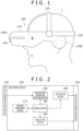
- FIG. 1 is a diagram schematically illustrating an overview of an appearance configuration of a head-mounted display 100 according to an embodiment, and shows that a user 1 is wearing the head-mounted display 100. It is assumed that the head-mounted display 100 according to the embodiment is a non-see-through head-mounted display. Therefore, when the user 1 wears the head-mounted display 100, the head-mounted display 100 blocks out an outside world from a vision of the user 1 as illustrated in FIG. 1 . This allows the user 1 to focus on content videos presented by the head-mounted display 100, thus enhancing so-called "immersion.”
- the head-mounted display 100 includes a housing 110 and a fitting 120.
- the fitting 120 is a member used to fasten the housing 110 to a head of the user 1 and can be implemented, for example, by a tightening or elastic belt.
- the housing 110 accommodates a central processing unit (CPU) which is not shown, a movie presentation section 130a, and an audio presentation section 130b.
- the movie presentation section 130a includes, for example, a liquid crystal display (LCD) or organic electro-luminescence (EL).
- the audio presentation section 130b includes, for example, a speaker and an earphone.
- a "video” includes a "movie,” timely successive images, and "audio” that is played in synchronism with or independently of the movie.
- the head-mounted display 100 further includes an outside world measurement section 140 that measures information on an outside world of the housing 110.
- the outside world measurement section 140 will be described in detail later.
- FIG. 2 is a diagram schematically illustrating a functional configuration of the head-mounted display 100 according to the embodiment.
- the head-mounted display 100 includes an information presentation section 130, the outside world measurement section 140, a notification information detection section 150, a notification section 160, a position measurement section 170, a control section 180, and a video playing section 190.
- FIG. 2 illustrates a functional configuration for enabling the head-mounted display 100 according to the embodiment to notify an outside world condition to the user 1.
- FIG. 2 each of the elements described as a functional block for performing various processing tasks can be formed with a CPU, a main memory, and other large scale integrations (LSIs) in terms of hardware.
- LSIs large scale integrations
- each of the elements is implemented by a program loaded into the main memory. Therefore, it is understood by those skilled in the art that these functional blocks can be implemented in various ways by hardware alone, software alone, or a combination thereof and are not limited to any one of them.
- the video playing section 190 plays the content video presented to the user 1.
- the video playing section 190 plays the content acquired via an unshown memory card slot or universal serial bus (USB) or by wireless means such as wireless fidelity (Wi-Fi) (registered trademark).
- the information presentation section 130 includes the movie presentation section 130a and the audio presentation section 130b described above, presenting the video played by the video playing section 190 to the user 1.
- the information presentation section 130 causes the movie presentation section 130a to present movies, still images, and other information and the audio presentation section 130b to present audio information.
- the information presentation section 130 functions as a user interface for presenting information generated by the head-mounted display 100 to the user 1.
- the outside world measurement section 140 measures information on an outside world of the housing 110.
- the outside world measurement section 140 is provided at a position on the outside of the housing 110 of the head-mounted display 100 that matches the position in which the movie presentation section 130a is accommodated. Therefore, when the head-mounted display 100 is worn by the user 1, the outside world measurement section 140 can measure outside world information in the direction of line of sight of the user 1.
- the outside world measurement section 140 can be implemented, for example, by a camera designed to measure visible radiation or an infrared camera designed to measure infrared radiation. It should be noted that the outside world measurement section 140 may be a stereo camera with at least two cameras. This makes it possible to acquire depth information of a subject by analyzing information measured by the outside world measurement section 140.
- the notification information detection section 150 detects whether or not any notification information to be notified to the user 1 is contained in the information measured by the outside world measurement section 140. "Information to be notified” refers to information used to identify the extent to which the user 1 is allowed to move. More specifically, if the outside world measurement section 140 is a stereo camera, the notification information detection section 150 detects still objects that stand still of all subjects measured by the outside world measurement section 140, a stereo camera, as notification information. This can be implemented by a known 3D image analysis technology.
- the notification section 160 notifies the user 1 when notification information is detected by the notification information detection section 150.
- the notification section 160 may show, on the information presentation section 130, notification information to the effect that a still object exists in the outside world in the form of a message.
- a window showing a video of the still object may be displayed on the information presentation section 130.
- the notification section 160 may cause the information presentation section 130 to play notification information to the effect that a still object exists in the outside world in the form of audio information.
- the notification section 160 may cause the information presentation section 130 to play a warning tone indicating that a still object exists in the outside world. If the head-mounted display 100 has a vibrator (not shown), the user 1 may be notified by vibration.
- the position measurement section 170 detects where the head-mounted display 100 exists. More specifically, the position measurement section 170 measures the position of the head-mounted display 100 in the space where the head-mounted display 100 exists.
- the position measurement section 170 includes, for example, an acceleration sensor and an angular speed sensor, thus detecting a relative position of the head-mounted display 100 with respect to a reference point determined in advance by the user 1.
- the control section 180 comprehensively controls each of the different sections of the head-mounted display 100 described above.
- the control section 180 is implemented as a result of execution of the operating system of the head-mounted display 100 by the CPU (not shown) of the head-mounted display 100.
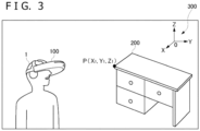
- FIG. 3 is a diagram schematically illustrating a scene in which the head-mounted display 100 according to the embodiment is used.
- the example in FIG. 3 shows that the user 1 is wearing the head-mounted display 100 in a room where a desk 200 exists.
- the user 1 wears the head-mounted display 100 and plays a 3D game.
- the user 1 advances through the game by manipulating a controller of a gaming device (not shown).
- the head-mounted display 100 presents a video that changes in accordance with the progress of the game to the user 1.
- the head-mounted display 100 is a non-see-through head-mounted display that presents 3D videos full of immersion to the user 1. Therefore, what the user 1 perceives from the videos presented by the head-mounted display 100 is a realistic experience. In some cases, the user 1 may move his or her head or body reflexively.
- the head-mounted display 100 can be made easier to use if the extent to which the user 1 is allowed to move, i.e., the area within which the user 1 can enjoy the game, can be presented. This can enhance the usability of the head-mounted display 100.
- the notification information detection section 150 detects a still object
- the notification to the user 1 by the notification section 160 may be triggered by the fact that the distance between the head-mounted display 100 and the still object becomes shorter than a given reference distance.
- the term "given reference distance” refers to a “notification reference distance” that serves as a reference for deciding whether or not the notification section 160 should notify notification information to the user 1.
- the notification reference distance is, for example, one meter.
- the notification section 160 notifies the user 1 accordingly if the distance between the still object and the head-mounted display 100 becomes shorter than one meter. This allows the user 1 to recognize that he or she has come close to the boundary of the movable area.
- the notification information detection section 150 need only identify the still object by analyzing the video measured by the outside world measurement section 140. Further, if the outside world measurement section 140 is a stereo camera, the notification information detection section 150 can estimate the distance to the still object by analyzing the video measured by the outside world measurement section 140.
- the movement of the head-mounted display 100 is not negligible.
- analyzing the video measured by the outside world measurement section 140 alone may lead to low accuracy in identifying the still object.
- the reason for this is that the position of the still object, despite standing still object, changes in the video measured by the outside world measurement section 140 because of the movement of the head-mounted display 100.
- the notification section 160 may acquire the distance between the head-mounted display 100 and the still object based on the position of the head-mounted display 100 detected by the position measurement section 170.
- the user 1 determines a reference point for position measurement in advance before using the head-mounted display 100.
- the user 1 determines a point P, a point in the desk 200, as the reference point P.
- the user 1 establishes a Cartesian coordinate system 300 with its origin set at an arbitrary point in the space where the user 1 and the desk 200 exist.
- the position of the reference point P can be set uniquely as position coordinates of the Cartesian coordinate system 300.
- the coordinates of the reference point P are set at P(X 1 , Y 1 , Z 1 ).
- the user 1 moves the head-mounted display 100 to the position of the reference point P first and then instructs the head-mounted display 100 to start measurement. This can be accomplished, for example, by pressing a measurement start button (not shown) attached to the housing 110.
- the position measurement section 170 includes an acceleration sensor and an angular speed sensor.
- the position measurement section 170 integrates output values of the sensors after being instructed to start measurement by the user 1, thus allowing for calculation of the relative position of the head-mounted display 100 with respect to the reference point P. Further, the position measurement section 170 can acquire the position coordinates of the head-mounted display 100 in the Cartesian coordinate system 300 by merging the relative position of the head-mounted display 100 with the coordinates P(X 1 , Y 1 , Z 1 ) of the reference point P.
- the notification section 160 can calculate the distance between the still object and the head-mounted display 100 without using the coordinates P (X 1 , Y 1 , Z 1 ) of the reference point P.
- the notification information detection section 150 can identify the reason why the subject measured by the outside world measurement section 140 moved in the video. This provides improved accuracy in extraction of still objects by the notification information detection section 150. Further, the distance between the still object and the head-mounted display 100 can be acquired with higher accuracy than by acquiring depth information of the subject through analysis of information shot by the outside world measurement section 140, a stereo camera.
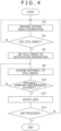
- FIG. 4 is a flowchart describing an information processing flow handled by the head-mounted display 100 according to the embodiment. The processes in this flowchart begin, for example, when the head-mounted display 100 is powered on.
- the outside world measurement section 140 measures outside world information in the direction of line of sight of the user 1 when the head-mounted display 100 is worn by the user 1 (S2). While a still object remains unfound by the notification information detection section 150 through analysis of the video measured by the outside world measurement section 140 (N in S4), the outside world measurement section 140 continues with measurement of the outside world.
- the notification information detection section 150 sets the detected still object as notification information (S6).
- the notification section 160 acquires a distance L from the head-mounted display 100 to the still object (S8) based on the position of the head-mounted display 100 detected by the position measurement section 170.
- the notification section 160 When the distance L from the head-mounted display 100 to the still object is equal to or longer than a given reference distance L T (N in S10), the notification section 160 returns to step S8 to continue with acquisition of the distance L. If the distance L from the head-mounted display 100 to the still object is shorter than the given reference distance L T (Y in S10), the notification section 160 notifies the user via the information presentation section 130 that a still object is close (S12).
- the head-mounted display 100 While the user 1 continues to use the head-mounted display 100 (N in S14), the head-mounted display 100 returns to step S2 to continue with the series of processes described above. When the user 1 stops using the head-mounted display 100 (Y in S14), the processes in this flowchart are terminated.
- the head-mounted display 100 can provide a technology for notifying an outside world condition to the user 1 wearing the non-see-through head-mounted display.
- the head-mounted display 100 worn by the user 1 comes close to a still object in the outside world, information to that effect is presented on the information presentation section 130 of the head-mounted display 100. This allows the user 1 to find out that he or she has come close to the boundary of the area within which the user 1 is allowed to freely move even with the non-see-through head-mounted display 100 on.
- the notification information detection section 150 detected a still object in outside world information measured by the outside world measurement section 140 as notification information.
- the notification information detection section 150 may detect, as notification information, an object moving at a given speed or more in outside world information measured by the outside world measurement section 140.
- the unshown notification information detection section 150 detects a moving object in the outside world information measured by the outside world measurement section 140, notifying the result thereof to the user 1.
- the head-mounted display 100 can adaptively notify the boundary thereof to the user 1.
- Head-mounted display 110 Housing, 120 Fitting, 130 Information presentation section, 130a Movie presentation section, 130b Audio presentation section, 140 Outside world measurement section, 150 Notification information detection section, 160 Notification section, 170 Position measurement section, 180 Control section, 190 Video playing section, 200 Desk, 300 Cartesian coordinate system.
- the present invention is applicable to information processing technologies for head-mounted displays.
Description
- The present invention relates to a head-mounted display and an information processing method carried out by the head-mounted display.
- Recent years have seen advancement in technological developments for presenting stereoscopic videos, contributing to widespread use of head-mounted displays that permit presentation of stereoscopic videos with depth. Capable of presenting videos having depth to users, head-mounted displays are now used as presentation devices of three-dimensional (3D) content such as 3D movies and 3D games.
WO 2013/952855 A2 relates to detecting physical objects near a substantially transparent head-mounted display system and activating a collision-avoidance action to alert a user of the detected objects. Detection techniques may include receiving data from distance and/or relative movement sensors and using this data as a basis for determining an appropriate collision-avoidance action. Exemplary collision-avoidance actions may include de-emphasizing virtual objects displayed on the HMD to provide a less cluttered view of the physical objects through the substantially transparent display and/or presenting new virtual objects. - A head-mounted display is worn in such a manner as to cover both eyeballs of the user, an observer. Some head-mounted displays are non-see-through ones. Each of these head-mounted displays blocks out an outside world from a user's vision and presents a video when worn by the user. In general, when wearing such a non-see-through head-mounted display, the user has difficulty in viewing a real-world scene in the outside world.
- For example, if a non-see-through head-mounted display is used where the user is allowed to move or play to a limited extent such as at home, it is convenient to present, to the user, the extent to which the user wearing the head-mounted display is allowed to move.
- The present invention has been devised in light of the foregoing, and it is an object of the present invention to provide a technology for notifying an outside world condition to a user wearing a non-see-through head-mounted display.
- In order to solve the above problem, a head-mounted display according to a mode of the present invention blocks out an outside world from a user's vision and presents a video when worn by the user. The head-mounted display includes an outside world measurement section, a notification information detection section, and a notification section. The outside world measurement section measures outside world information. The notification information detection section detects whether or not the information measured by the outside world measurement section contains any notification information to be notified to the user. The notification section notifies the user when the notification information detection section detects notification information.
- Another mode of the present invention is an information processing method carried out by a processor of a head-mounted display for blocking out an outside world from a user's vision when worn by the user to present a video. This method includes a step of measuring outside world information. This method includes another step of detecting whether or not the measured information contains any notification information to be notified to the user. This method includes still another step of notifying the user when notification information is detected.
- Still another mode of the present invention is a program for causing a computer to perform the steps of the above method.
- This program may be supplied as part of firmware built into an apparatus to basically control hardware resources such as video, audio, game apparatus, and head-mounted display. This firmware is stored in a semiconductor memory such as read only memory (ROM) or flash memory in the apparatus. In order to supply this firmware or to update part of the firmware, a computer-readable recording medium recording this program may be supplied or transmitted via a communication line.
- It should be noted that arbitrary combinations of the above components and conversions of expressions of the present invention between method, device, system, computer program, data structure, recording medium and so on are also effective as modes of the present invention.
- The present invention provides a technology for notifying an outside world condition to a user wearing a non-see-through head-mounted display.
-
- [
FIG. 1 ]
FIG. 1 is a diagram schematically illustrating an overview of an appearance configuration of a head-mounted display according to an embodiment. - [
FIG. 2 ]
FIG. 2 is a diagram schematically illustrating a functional configuration of the head-mounted display according to the embodiment. - [
FIG. 3 ]
FIG. 3 is a diagram schematically illustrating a scene in which the head-mounted display according to the embodiment is used. - [
FIG. 4 ]
FIG. 4 is a flowchart describing an information processing flow handled by the head-mounted display according to the embodiment. -
FIG. 1 is a diagram schematically illustrating an overview of an appearance configuration of a head-mounteddisplay 100 according to an embodiment, and shows that auser 1 is wearing the head-mounteddisplay 100. It is assumed that the head-mounteddisplay 100 according to the embodiment is a non-see-through head-mounted display. Therefore, when theuser 1 wears the head-mounteddisplay 100, the head-mounteddisplay 100 blocks out an outside world from a vision of theuser 1 as illustrated inFIG. 1 . This allows theuser 1 to focus on content videos presented by the head-mounteddisplay 100, thus enhancing so-called "immersion." - The head-mounted
display 100 includes ahousing 110 and afitting 120. Thefitting 120 is a member used to fasten thehousing 110 to a head of theuser 1 and can be implemented, for example, by a tightening or elastic belt. Thehousing 110 accommodates a central processing unit (CPU) which is not shown, amovie presentation section 130a, and anaudio presentation section 130b. Themovie presentation section 130a includes, for example, a liquid crystal display (LCD) or organic electro-luminescence (EL). Theaudio presentation section 130b includes, for example, a speaker and an earphone. It should be noted that, in the present specification, a "video" includes a "movie," timely successive images, and "audio" that is played in synchronism with or independently of the movie. The head-mounteddisplay 100 further includes an outsideworld measurement section 140 that measures information on an outside world of thehousing 110. The outsideworld measurement section 140 will be described in detail later. -
FIG. 2 is a diagram schematically illustrating a functional configuration of the head-mounteddisplay 100 according to the embodiment. The head-mounteddisplay 100 includes aninformation presentation section 130, the outsideworld measurement section 140, a notificationinformation detection section 150, anotification section 160, aposition measurement section 170, acontrol section 180, and avideo playing section 190. -
FIG. 2 illustrates a functional configuration for enabling the head-mounteddisplay 100 according to the embodiment to notify an outside world condition to theuser 1. Other part of the configuration is not shown. InFIG. 2 , each of the elements described as a functional block for performing various processing tasks can be formed with a CPU, a main memory, and other large scale integrations (LSIs) in terms of hardware. In terms of software, on the other hand, each of the elements is implemented by a program loaded into the main memory. Therefore, it is understood by those skilled in the art that these functional blocks can be implemented in various ways by hardware alone, software alone, or a combination thereof and are not limited to any one of them. - The
video playing section 190 plays the content video presented to theuser 1. Thevideo playing section 190 plays the content acquired via an unshown memory card slot or universal serial bus (USB) or by wireless means such as wireless fidelity (Wi-Fi) (registered trademark). Theinformation presentation section 130 includes themovie presentation section 130a and theaudio presentation section 130b described above, presenting the video played by thevideo playing section 190 to theuser 1. Theinformation presentation section 130 causes themovie presentation section 130a to present movies, still images, and other information and theaudio presentation section 130b to present audio information. Theinformation presentation section 130 functions as a user interface for presenting information generated by the head-mounteddisplay 100 to theuser 1. - The outside
world measurement section 140 measures information on an outside world of thehousing 110. The outsideworld measurement section 140 is provided at a position on the outside of thehousing 110 of the head-mounteddisplay 100 that matches the position in which themovie presentation section 130a is accommodated. Therefore, when the head-mounteddisplay 100 is worn by theuser 1, the outsideworld measurement section 140 can measure outside world information in the direction of line of sight of theuser 1. - The outside
world measurement section 140 can be implemented, for example, by a camera designed to measure visible radiation or an infrared camera designed to measure infrared radiation. It should be noted that the outsideworld measurement section 140 may be a stereo camera with at least two cameras. This makes it possible to acquire depth information of a subject by analyzing information measured by the outsideworld measurement section 140. - The notification
information detection section 150 detects whether or not any notification information to be notified to theuser 1 is contained in the information measured by the outsideworld measurement section 140. "Information to be notified" refers to information used to identify the extent to which theuser 1 is allowed to move. More specifically, if the outsideworld measurement section 140 is a stereo camera, the notificationinformation detection section 150 detects still objects that stand still of all subjects measured by the outsideworld measurement section 140, a stereo camera, as notification information. This can be implemented by a known 3D image analysis technology. - The
notification section 160 notifies theuser 1 when notification information is detected by the notificationinformation detection section 150. For example, thenotification section 160 may show, on theinformation presentation section 130, notification information to the effect that a still object exists in the outside world in the form of a message. Alternatively, a window showing a video of the still object may be displayed on theinformation presentation section 130. Thenotification section 160 may cause theinformation presentation section 130 to play notification information to the effect that a still object exists in the outside world in the form of audio information. Alternatively, thenotification section 160 may cause theinformation presentation section 130 to play a warning tone indicating that a still object exists in the outside world. If the head-mounteddisplay 100 has a vibrator (not shown), theuser 1 may be notified by vibration. - The
position measurement section 170 detects where the head-mounteddisplay 100 exists. More specifically, theposition measurement section 170 measures the position of the head-mounteddisplay 100 in the space where the head-mounteddisplay 100 exists. Theposition measurement section 170 includes, for example, an acceleration sensor and an angular speed sensor, thus detecting a relative position of the head-mounteddisplay 100 with respect to a reference point determined in advance by theuser 1. - The
control section 180 comprehensively controls each of the different sections of the head-mounteddisplay 100 described above. Thecontrol section 180 is implemented as a result of execution of the operating system of the head-mounteddisplay 100 by the CPU (not shown) of the head-mounteddisplay 100. -
FIG. 3 is a diagram schematically illustrating a scene in which the head-mounteddisplay 100 according to the embodiment is used. The example inFIG. 3 shows that theuser 1 is wearing the head-mounteddisplay 100 in a room where adesk 200 exists. - We consider, for example, a case in which the
user 1 wears the head-mounteddisplay 100 and plays a 3D game. In this case, theuser 1 advances through the game by manipulating a controller of a gaming device (not shown). The head-mounteddisplay 100 presents a video that changes in accordance with the progress of the game to theuser 1. - As described above, the head-mounted
display 100 according to the embodiment is a non-see-through head-mounted display that presents 3D videos full of immersion to theuser 1. Therefore, what theuser 1 perceives from the videos presented by the head-mounteddisplay 100 is a realistic experience. In some cases, theuser 1 may move his or her head or body reflexively. When the user uses the head-mounteddisplay 100 in a relatively small space such as a room at home, the head-mounteddisplay 100 can be made easier to use if the extent to which theuser 1 is allowed to move, i.e., the area within which theuser 1 can enjoy the game, can be presented. This can enhance the usability of the head-mounteddisplay 100. - For this reason, when the notification
information detection section 150 detects a still object, the notification to theuser 1 by thenotification section 160 may be triggered by the fact that the distance between the head-mounteddisplay 100 and the still object becomes shorter than a given reference distance. - Here, the term "given reference distance" refers to a "notification reference distance" that serves as a reference for deciding whether or not the
notification section 160 should notify notification information to theuser 1. Although may be determined experimentally in consideration of the anticipated manner in which the head-mounteddisplay 100 is used and so on, the notification reference distance is, for example, one meter. Thenotification section 160 notifies theuser 1 accordingly if the distance between the still object and the head-mounteddisplay 100 becomes shorter than one meter. This allows theuser 1 to recognize that he or she has come close to the boundary of the movable area. - If the movement of the head-mounted
display 100 is negligible, for example, as when theuser 1 uses the head-mounteddisplay 100 seated, the still object is shot as an immobile subject in the video shot by the outsideworld measurement section 140. In such a case, the notificationinformation detection section 150 need only identify the still object by analyzing the video measured by the outsideworld measurement section 140. Further, if the outsideworld measurement section 140 is a stereo camera, the notificationinformation detection section 150 can estimate the distance to the still object by analyzing the video measured by the outsideworld measurement section 140. - In contrast, if the
user 1 uses the head-mounteddisplay 100, for example, while standing and moving, the movement of the head-mounteddisplay 100 is not negligible. In this case, analyzing the video measured by the outsideworld measurement section 140 alone may lead to low accuracy in identifying the still object. The reason for this is that the position of the still object, despite standing still object, changes in the video measured by the outsideworld measurement section 140 because of the movement of the head-mounteddisplay 100. - Therefore, the
notification section 160 may acquire the distance between the head-mounteddisplay 100 and the still object based on the position of the head-mounteddisplay 100 detected by theposition measurement section 170. In this case, theuser 1 determines a reference point for position measurement in advance before using the head-mounteddisplay 100. In the example shown inFIG. 3 , theuser 1 determines a point P, a point in thedesk 200, as the reference point P. - As illustrated in
FIG. 3 , theuser 1 establishes a Cartesian coordinatesystem 300 with its origin set at an arbitrary point in the space where theuser 1 and thedesk 200 exist. The position of the reference point P can be set uniquely as position coordinates of the Cartesian coordinatesystem 300. InFIG. 3 , the coordinates of the reference point P are set at P(X1, Y1, Z1). Theuser 1 moves the head-mounteddisplay 100 to the position of the reference point P first and then instructs the head-mounteddisplay 100 to start measurement. This can be accomplished, for example, by pressing a measurement start button (not shown) attached to thehousing 110. - The
position measurement section 170 includes an acceleration sensor and an angular speed sensor. Theposition measurement section 170 integrates output values of the sensors after being instructed to start measurement by theuser 1, thus allowing for calculation of the relative position of the head-mounteddisplay 100 with respect to the reference point P. Further, theposition measurement section 170 can acquire the position coordinates of the head-mounteddisplay 100 in the Cartesian coordinatesystem 300 by merging the relative position of the head-mounteddisplay 100 with the coordinates P(X1, Y1, Z1) of the reference point P. In particular, if theuser 1 specifies the reference point P as a point on the still object, thenotification section 160 can calculate the distance between the still object and the head-mounteddisplay 100 without using the coordinates P (X1, Y1, Z1) of the reference point P. - By acquiring the position coordinates of the head-mounted
display 100, i.e., the movement of the head-mounteddisplay 100, the notificationinformation detection section 150 can identify the reason why the subject measured by the outsideworld measurement section 140 moved in the video. This provides improved accuracy in extraction of still objects by the notificationinformation detection section 150. Further, the distance between the still object and the head-mounteddisplay 100 can be acquired with higher accuracy than by acquiring depth information of the subject through analysis of information shot by the outsideworld measurement section 140, a stereo camera. -
FIG. 4 is a flowchart describing an information processing flow handled by the head-mounteddisplay 100 according to the embodiment. The processes in this flowchart begin, for example, when the head-mounteddisplay 100 is powered on. - The outside
world measurement section 140 measures outside world information in the direction of line of sight of theuser 1 when the head-mounteddisplay 100 is worn by the user 1 (S2). While a still object remains unfound by the notificationinformation detection section 150 through analysis of the video measured by the outside world measurement section 140 (N in S4), the outsideworld measurement section 140 continues with measurement of the outside world. - When a still object is found in the video measured by the outside world measurement section 140 (Y in S4), the notification
information detection section 150 sets the detected still object as notification information (S6). Thenotification section 160 acquires a distance L from the head-mounteddisplay 100 to the still object (S8) based on the position of the head-mounteddisplay 100 detected by theposition measurement section 170. - When the distance L from the head-mounted
display 100 to the still object is equal to or longer than a given reference distance LT (N in S10), thenotification section 160 returns to step S8 to continue with acquisition of the distance L. If the distance L from the head-mounteddisplay 100 to the still object is shorter than the given reference distance LT (Y in S10), thenotification section 160 notifies the user via theinformation presentation section 130 that a still object is close (S12). - While the
user 1 continues to use the head-mounted display 100 (N in S14), the head-mounteddisplay 100 returns to step S2 to continue with the series of processes described above. When theuser 1 stops using the head-mounted display 100 (Y in S14), the processes in this flowchart are terminated. - As described above, the head-mounted
display 100 according to the embodiment can provide a technology for notifying an outside world condition to theuser 1 wearing the non-see-through head-mounted display. - In particular, if the head-mounted
display 100 worn by theuser 1 comes close to a still object in the outside world, information to that effect is presented on theinformation presentation section 130 of the head-mounteddisplay 100. This allows theuser 1 to find out that he or she has come close to the boundary of the area within which theuser 1 is allowed to freely move even with the non-see-through head-mounteddisplay 100 on. - Thus, the present invention has been described based on the embodiment. It is to be understood by those skilled in the art that the embodiment is illustrative, that combinations of components and processes thereof can be modified in various ways, and that these modification examples also fall within the scope of the present invention.
- In the above description, a case was described in which the notification
information detection section 150 detected a still object in outside world information measured by the outsideworld measurement section 140 as notification information. Instead or in addition thereto, the notificationinformation detection section 150 may detect, as notification information, an object moving at a given speed or more in outside world information measured by the outsideworld measurement section 140. - For example, if the
user 1 uses the head-mounteddisplay 100 according to the embodiment in a room with an inwardly opening door, the area within which theuser 1 is allowed to freely move changes when the door is opened by somebody other than theuser 1. That is, if the inwardly opening door opens, this means that the door enters into the room, thus resulting in a smaller area within which theuser 1 is allowed to move. For this reason, the unshown notificationinformation detection section 150 detects a moving object in the outside world information measured by the outsideworld measurement section 140, notifying the result thereof to theuser 1. - This allows the head-mounted
display 100 according to a modification example to notify any change in the outside world condition to theuser 1 wearing the non-see-through head-mounted display. Even in the event of a change in the area within which theuser 1 is allowed to move, the head-mounteddisplay 100 can adaptively notify the boundary thereof to theuser 1. - 100 Head-mounted display, 110 Housing, 120 Fitting, 130 Information presentation section, 130a Movie presentation section, 130b Audio presentation section, 140 Outside world measurement section, 150 Notification information detection section, 160 Notification section, 170 Position measurement section, 180 Control section, 190 Video playing section, 200 Desk, 300 Cartesian coordinate system.
- The present invention is applicable to information processing technologies for head-mounted displays.
Claims (4)
- A head-mounted display (100) for blocking out an outside world from a user's vision when worn by the user to present a video, the head-mounted display (100) comprising:an outside world measurement section (140), constituted by a camera, which is adapted to measure outside world information;a position measurement section (170), constituted by an accelerometer and a gyroscope, which is adapted to measure whether a position of the head-mounted display (100) in space changes;a notification information detection section (150) adapted to detect whether or not the information measured by the outside world measurement section (140) indicates the presence of a still object (200) and to detect the distance to the still object (200) based either on the video captured by the camera when the position measurement section (170) detects that the position of the head-mounted display (100) in space has not changed, or on the measurements of the accelerometer and the gyroscope of the position measurement section (170) when the position measurement section detects that the position of the head-mounted display (100) in space has changed;
anda notification section (160) adapted to notify the user when the notification information detection section (150) detects presence of a still object (200) at a distance shorter than a given reference distance, whereinthe notification section (160) acquires the distance between the position of the head-mounted display (100) and the still object (200) based on the position of the head-mounted display (100) detected by the position measurement section (170) by making use of a reference point (P) for position measurement determined before the movement of the head mounted display (100), andthe position measurement section (170) is configured to set the reference point (P) on the still object (200) by starting measurement of position changes while the head mounted display is located at the reference point (P) and to calculate the distance between the position of the head-mounted display (100) and the still object (200) by integrating position changes with respect to the reference point (P) on the still object (200). - The head-mounted display (100) of claim 1, whereinthe outside world measurement section (140) is a stereo camera with at least two cameras, andthe notification information detection section (150) detects presence of the still object (200) by using the stereo camera.
- An information processing method carried out by a processor of a head-mounted display (100) for blocking out an outside world from a user's vision when worn by the user to present a video, the method comprising:a step of measuring outside world information by a camera;a step of measuring whether a position of the head-mounted display (100) in space changes by an accelerometer and a gyroscope;a step of detecting whether or not the measured information indicates the presence of a still object (200), and of detecting the distance to the still object (200) based either on the video captured by the camera when it has been detected that the position of the head-mounted display (100) in space has not changed, or on the measurements of the accelerometer and the gyroscope when it has been detected that the position of the head-mounted display (100) in space has changed; anda step of notifying the user when the presence of the still object (200) is detected at a distance shorter than a given reference distance, whereinthe distance between the position of the head-mounted display (100) and the still object (200) are acquired based on the position of the head-mounted display (100) detected by accelerometer and the gyroscope by making use of a reference point (P) for position measurement determined before the movement of the head mounted display (100), andthe reference point (P) is set on the still object (200) by starting a measurement of position changes while the head mounted display is located at the reference point (P) and the distance between the position of the head-mounted display (100) and the still object (200) is calculated by integrating position changes with respect to the reference point (P) on the still object (200).
- A program causing a processor of a head-mounted display (100) for blocking out an outside world from a user's vision when worn by the user to present a video to carry out the method of claim 3.
Priority Applications (1)
| Application Number | Priority Date | Filing Date | Title |
|---|---|---|---|
| EP23192981.1A EP4273672A3 (en) | 2014-11-04 | 2015-10-28 | Head mounted display and information processing method |
Applications Claiming Priority (2)
| Application Number | Priority Date | Filing Date | Title |
|---|---|---|---|
| JP2014224154A JP2016090772A (en) | 2014-11-04 | 2014-11-04 | Head-mounted display and information processing method |
| PCT/JP2015/080383 WO2016072327A1 (en) | 2014-11-04 | 2015-10-28 | Head mounted display and information processing method |
Related Child Applications (2)
| Application Number | Title | Priority Date | Filing Date |
|---|---|---|---|
| EP23192981.1A Division-Into EP4273672A3 (en) | 2014-11-04 | 2015-10-28 | Head mounted display and information processing method |
| EP23192981.1A Division EP4273672A3 (en) | 2014-11-04 | 2015-10-28 | Head mounted display and information processing method |
Publications (3)
| Publication Number | Publication Date |
|---|---|
| EP3217384A1 EP3217384A1 (en) | 2017-09-13 |
| EP3217384A4 EP3217384A4 (en) | 2018-07-04 |
| EP3217384B1 true EP3217384B1 (en) | 2023-10-04 |
Family
ID=55909053
Family Applications (2)
| Application Number | Title | Priority Date | Filing Date |
|---|---|---|---|
| EP15856535.8A Active EP3217384B1 (en) | 2014-11-04 | 2015-10-28 | Head mounted display and information processing method |
| EP23192981.1A Pending EP4273672A3 (en) | 2014-11-04 | 2015-10-28 | Head mounted display and information processing method |
Family Applications After (1)
| Application Number | Title | Priority Date | Filing Date |
|---|---|---|---|
| EP23192981.1A Pending EP4273672A3 (en) | 2014-11-04 | 2015-10-28 | Head mounted display and information processing method |
Country Status (4)
| Country | Link |
|---|---|
| US (4) | US10185146B2 (en) |
| EP (2) | EP3217384B1 (en) |
| JP (1) | JP2016090772A (en) |
| WO (1) | WO2016072327A1 (en) |
Families Citing this family (4)
| Publication number | Priority date | Publication date | Assignee | Title |
|---|---|---|---|---|
| JP2016090772A (en) * | 2014-11-04 | 2016-05-23 | 株式会社ソニー・コンピュータエンタテインメント | Head-mounted display and information processing method |
| US10713848B2 (en) | 2017-04-06 | 2020-07-14 | Htc Corporation | System and method for providing simulated environment |
| KR102521557B1 (en) * | 2018-01-04 | 2023-04-14 | 삼성전자주식회사 | Electronic device controlling image display based on scroll input and method thereof |
| JP2023104609A (en) * | 2022-01-18 | 2023-07-28 | 株式会社ソニー・インタラクティブエンタテインメント | Information processing apparatus and information processing method |
Family Cites Families (11)
| Publication number | Priority date | Publication date | Assignee | Title |
|---|---|---|---|---|
| JP5062626B2 (en) * | 2007-10-23 | 2012-10-31 | 学校法人玉川学園 | Object identification device |
| JP4941265B2 (en) * | 2007-12-07 | 2012-05-30 | トヨタ自動車株式会社 | Obstacle determination device |
| JP2011205358A (en) * | 2010-03-25 | 2011-10-13 | Fujifilm Corp | Head-mounted display device |
| US9081177B2 (en) * | 2011-10-07 | 2015-07-14 | Google Inc. | Wearable computer with nearby object response |
| US9255813B2 (en) * | 2011-10-14 | 2016-02-09 | Microsoft Technology Licensing, Llc | User controlled real object disappearance in a mixed reality display |
| JP2013164737A (en) * | 2012-02-10 | 2013-08-22 | Nec Corp | Obstacle alarm display system, information processor, obstacle alarm display method, and obstacle alarm display program |
| GB2501768A (en) * | 2012-05-04 | 2013-11-06 | Sony Comp Entertainment Europe | Head mounted display |
| JP5580855B2 (en) * | 2012-06-12 | 2014-08-27 | 株式会社ソニー・コンピュータエンタテインメント | Obstacle avoidance device and obstacle avoidance method |
| JP5862785B2 (en) | 2012-09-03 | 2016-02-16 | トヨタ自動車株式会社 | Collision determination device and collision determination method |
| US20140152530A1 (en) * | 2012-12-03 | 2014-06-05 | Honeywell International Inc. | Multimedia near to eye display system |
| JP2016090772A (en) * | 2014-11-04 | 2016-05-23 | 株式会社ソニー・コンピュータエンタテインメント | Head-mounted display and information processing method |
-
2014
- 2014-11-04 JP JP2014224154A patent/JP2016090772A/en active Pending
-
2015
- 2015-10-28 EP EP15856535.8A patent/EP3217384B1/en active Active
- 2015-10-28 US US15/501,372 patent/US10185146B2/en active Active
- 2015-10-28 EP EP23192981.1A patent/EP4273672A3/en active Pending
- 2015-10-28 WO PCT/JP2015/080383 patent/WO2016072327A1/en active Application Filing
-
2018
- 2018-12-13 US US16/218,722 patent/US10914947B2/en active Active
-
2021
- 2021-01-08 US US17/144,206 patent/US20210132378A1/en active Pending
-
2023
- 2023-11-09 US US18/505,185 patent/US20240069339A1/en active Pending
Also Published As
| Publication number | Publication date |
|---|---|
| US20190113749A1 (en) | 2019-04-18 |
| JP2016090772A (en) | 2016-05-23 |
| US20170219822A1 (en) | 2017-08-03 |
| US20240069339A1 (en) | 2024-02-29 |
| US20210132378A1 (en) | 2021-05-06 |
| US10914947B2 (en) | 2021-02-09 |
| US10185146B2 (en) | 2019-01-22 |
| EP4273672A2 (en) | 2023-11-08 |
| EP4273672A3 (en) | 2023-12-27 |
| WO2016072327A1 (en) | 2016-05-12 |
| EP3217384A1 (en) | 2017-09-13 |
| EP3217384A4 (en) | 2018-07-04 |
Similar Documents
| Publication | Publication Date | Title |
|---|---|---|
| US20240069339A1 (en) | Head mounted display and information processing method | |
| EP3241088B1 (en) | Methods and systems for user interaction within virtual or augmented reality scene using head mounted display | |
| CN110647237B (en) | Gesture-based content sharing in an artificial reality environment | |
| JP6422137B2 (en) | Perceptual-based predictive tracking for head-mounted displays | |
| US10908694B2 (en) | Object motion tracking with remote device | |
| US11017257B2 (en) | Information processing device, information processing method, and program | |
| US10438411B2 (en) | Display control method for displaying a virtual reality menu and system for executing the display control method | |
| JP2017090979A (en) | Information processing unit, information process system, and information processing method | |
| EP3389020A1 (en) | Information processing device, information processing method, and program | |
| US20150228118A1 (en) | Motion modeling in visual tracking | |
| JP6675209B2 (en) | Information processing apparatus and user guide presentation method | |
| KR20160032817A (en) | Head-mounted display controlled by tapping, method for controlling the same and computer program for controlling the same | |
| US20220335734A1 (en) | Head-mounted display, display control method, and program | |
| EP3528024B1 (en) | Information processing device, information processing method, and program | |
| JP7085578B2 (en) | Information processing device, user guide presentation method, and head-mounted display | |
| EP3508951B1 (en) | Electronic device for controlling image display based on scroll input | |
| CN112119451A (en) | Information processing apparatus, information processing method, and program | |
| JP6467039B2 (en) | Information processing device |
Legal Events
| Date | Code | Title | Description |
|---|---|---|---|
| STAA | Information on the status of an ep patent application or granted ep patent |
Free format text: STATUS: THE INTERNATIONAL PUBLICATION HAS BEEN MADE |
|
| PUAI | Public reference made under article 153(3) epc to a published international application that has entered the european phase |
Free format text: ORIGINAL CODE: 0009012 |
|
| STAA | Information on the status of an ep patent application or granted ep patent |
Free format text: STATUS: REQUEST FOR EXAMINATION WAS MADE |
|
| 17P | Request for examination filed |
Effective date: 20170113 |
|
| AK | Designated contracting states |
Kind code of ref document: A1 Designated state(s): AL AT BE BG CH CY CZ DE DK EE ES FI FR GB GR HR HU IE IS IT LI LT LU LV MC MK MT NL NO PL PT RO RS SE SI SK SM TR |
|
| AX | Request for extension of the european patent |
Extension state: BA ME |
|
| DAV | Request for validation of the european patent (deleted) | ||
| DAX | Request for extension of the european patent (deleted) | ||
| A4 | Supplementary search report drawn up and despatched |
Effective date: 20180601 |
|
| RIC1 | Information provided on ipc code assigned before grant |
Ipc: G09G 5/00 20060101ALI20180525BHEP Ipc: G06F 3/01 20060101ALI20180525BHEP Ipc: G06T 19/00 20110101ALI20180525BHEP Ipc: H04N 5/64 20060101ALI20180525BHEP Ipc: G09G 3/20 20060101AFI20180525BHEP Ipc: G09G 5/377 20060101ALI20180525BHEP |
|
| STAA | Information on the status of an ep patent application or granted ep patent |
Free format text: STATUS: EXAMINATION IS IN PROGRESS |
|
| 17Q | First examination report despatched |
Effective date: 20190416 |
|
| STAA | Information on the status of an ep patent application or granted ep patent |
Free format text: STATUS: EXAMINATION IS IN PROGRESS |
|
| GRAP | Despatch of communication of intention to grant a patent |
Free format text: ORIGINAL CODE: EPIDOSNIGR1 |
|
| STAA | Information on the status of an ep patent application or granted ep patent |
Free format text: STATUS: GRANT OF PATENT IS INTENDED |
|
| INTG | Intention to grant announced |
Effective date: 20230425 |
|
| GRAS | Grant fee paid |
Free format text: ORIGINAL CODE: EPIDOSNIGR3 |
|
| GRAA | (expected) grant |
Free format text: ORIGINAL CODE: 0009210 |
|
| STAA | Information on the status of an ep patent application or granted ep patent |
Free format text: STATUS: THE PATENT HAS BEEN GRANTED |
|
| AK | Designated contracting states |
Kind code of ref document: B1 Designated state(s): AL AT BE BG CH CY CZ DE DK EE ES FI FR GB GR HR HU IE IS IT LI LT LU LV MC MK MT NL NO PL PT RO RS SE SI SK SM TR |
|
| REG | Reference to a national code |
Ref country code: GB Ref legal event code: FG4D |
|
| REG | Reference to a national code |
Ref country code: CH Ref legal event code: EP |
|
| REG | Reference to a national code |
Ref country code: IE Ref legal event code: FG4D |
|
| REG | Reference to a national code |
Ref country code: DE Ref legal event code: R096 Ref document number: 602015085986 Country of ref document: DE |
|
| PGFP | Annual fee paid to national office [announced via postgrant information from national office to epo] |
Ref country code: GB Payment date: 20231121 Year of fee payment: 9 |
|
| REG | Reference to a national code |
Ref country code: LT Ref legal event code: MG9D |
|
| REG | Reference to a national code |
Ref country code: NL Ref legal event code: MP Effective date: 20231004 |
|
| REG | Reference to a national code |
Ref country code: AT Ref legal event code: MK05 Ref document number: 1618591 Country of ref document: AT Kind code of ref document: T Effective date: 20231004 |
|
| PG25 | Lapsed in a contracting state [announced via postgrant information from national office to epo] |
Ref country code: NL Free format text: LAPSE BECAUSE OF FAILURE TO SUBMIT A TRANSLATION OF THE DESCRIPTION OR TO PAY THE FEE WITHIN THE PRESCRIBED TIME-LIMIT Effective date: 20231004 |
|
| PG25 | Lapsed in a contracting state [announced via postgrant information from national office to epo] |
Ref country code: GR Free format text: LAPSE BECAUSE OF FAILURE TO SUBMIT A TRANSLATION OF THE DESCRIPTION OR TO PAY THE FEE WITHIN THE PRESCRIBED TIME-LIMIT Effective date: 20240105 |
|
| PG25 | Lapsed in a contracting state [announced via postgrant information from national office to epo] |
Ref country code: IS Free format text: LAPSE BECAUSE OF FAILURE TO SUBMIT A TRANSLATION OF THE DESCRIPTION OR TO PAY THE FEE WITHIN THE PRESCRIBED TIME-LIMIT Effective date: 20240204 |