EP3217355A1 - Methods and computer program products for calibrating stereo imaging systems by using a planar mirror - Google Patents
Methods and computer program products for calibrating stereo imaging systems by using a planar mirror Download PDFInfo
- Publication number
- EP3217355A1 EP3217355A1 EP16462003.1A EP16462003A EP3217355A1 EP 3217355 A1 EP3217355 A1 EP 3217355A1 EP 16462003 A EP16462003 A EP 16462003A EP 3217355 A1 EP3217355 A1 EP 3217355A1
- Authority
- EP
- European Patent Office
- Prior art keywords
- camera
- mirror
- image
- coordinate system
- images
- Prior art date
- Legal status (The legal status is an assumption and is not a legal conclusion. Google has not performed a legal analysis and makes no representation as to the accuracy of the status listed.)
- Withdrawn
Links
Images


Classifications
-
- G—PHYSICS
- G06—COMPUTING; CALCULATING OR COUNTING
- G06T—IMAGE DATA PROCESSING OR GENERATION, IN GENERAL
- G06T7/00—Image analysis
- G06T7/80—Analysis of captured images to determine intrinsic or extrinsic camera parameters, i.e. camera calibration
- G06T7/85—Stereo camera calibration
-
- G—PHYSICS
- G06—COMPUTING; CALCULATING OR COUNTING
- G06T—IMAGE DATA PROCESSING OR GENERATION, IN GENERAL
- G06T15/00—3D [Three Dimensional] image rendering
- G06T15/08—Volume rendering
-
- G—PHYSICS
- G06—COMPUTING; CALCULATING OR COUNTING
- G06T—IMAGE DATA PROCESSING OR GENERATION, IN GENERAL
- G06T7/00—Image analysis
- G06T7/50—Depth or shape recovery
- G06T7/55—Depth or shape recovery from multiple images
- G06T7/593—Depth or shape recovery from multiple images from stereo images
-
- G—PHYSICS
- G06—COMPUTING; CALCULATING OR COUNTING
- G06T—IMAGE DATA PROCESSING OR GENERATION, IN GENERAL
- G06T7/00—Image analysis
- G06T7/60—Analysis of geometric attributes
-
- G—PHYSICS
- G06—COMPUTING; CALCULATING OR COUNTING
- G06T—IMAGE DATA PROCESSING OR GENERATION, IN GENERAL
- G06T7/00—Image analysis
- G06T7/70—Determining position or orientation of objects or cameras
-
- H—ELECTRICITY
- H04—ELECTRIC COMMUNICATION TECHNIQUE
- H04N—PICTORIAL COMMUNICATION, e.g. TELEVISION
- H04N13/00—Stereoscopic video systems; Multi-view video systems; Details thereof
- H04N13/20—Image signal generators
- H04N13/204—Image signal generators using stereoscopic image cameras
- H04N13/207—Image signal generators using stereoscopic image cameras using a single 2D image sensor
- H04N13/211—Image signal generators using stereoscopic image cameras using a single 2D image sensor using temporal multiplexing
-
- H—ELECTRICITY
- H04—ELECTRIC COMMUNICATION TECHNIQUE
- H04N—PICTORIAL COMMUNICATION, e.g. TELEVISION
- H04N13/00—Stereoscopic video systems; Multi-view video systems; Details thereof
- H04N13/20—Image signal generators
- H04N13/204—Image signal generators using stereoscopic image cameras
- H04N13/207—Image signal generators using stereoscopic image cameras using a single 2D image sensor
- H04N13/221—Image signal generators using stereoscopic image cameras using a single 2D image sensor using the relative movement between cameras and objects
-
- H—ELECTRICITY
- H04—ELECTRIC COMMUNICATION TECHNIQUE
- H04N—PICTORIAL COMMUNICATION, e.g. TELEVISION
- H04N13/00—Stereoscopic video systems; Multi-view video systems; Details thereof
- H04N13/20—Image signal generators
- H04N13/204—Image signal generators using stereoscopic image cameras
- H04N13/207—Image signal generators using stereoscopic image cameras using a single 2D image sensor
- H04N13/236—Image signal generators using stereoscopic image cameras using a single 2D image sensor using varifocal lenses or mirrors
-
- H—ELECTRICITY
- H04—ELECTRIC COMMUNICATION TECHNIQUE
- H04N—PICTORIAL COMMUNICATION, e.g. TELEVISION
- H04N13/00—Stereoscopic video systems; Multi-view video systems; Details thereof
- H04N13/20—Image signal generators
- H04N13/204—Image signal generators using stereoscopic image cameras
- H04N13/246—Calibration of cameras
-
- H—ELECTRICITY
- H04—ELECTRIC COMMUNICATION TECHNIQUE
- H04N—PICTORIAL COMMUNICATION, e.g. TELEVISION
- H04N13/00—Stereoscopic video systems; Multi-view video systems; Details thereof
- H04N13/20—Image signal generators
- H04N13/282—Image signal generators for generating image signals corresponding to three or more geometrical viewpoints, e.g. multi-view systems
-
- G—PHYSICS
- G06—COMPUTING; CALCULATING OR COUNTING
- G06T—IMAGE DATA PROCESSING OR GENERATION, IN GENERAL
- G06T2207/00—Indexing scheme for image analysis or image enhancement
- G06T2207/10—Image acquisition modality
- G06T2207/10004—Still image; Photographic image
- G06T2207/10012—Stereo images
-
- G—PHYSICS
- G06—COMPUTING; CALCULATING OR COUNTING
- G06T—IMAGE DATA PROCESSING OR GENERATION, IN GENERAL
- G06T2207/00—Indexing scheme for image analysis or image enhancement
- G06T2207/10—Image acquisition modality
- G06T2207/10016—Video; Image sequence
- G06T2207/10021—Stereoscopic video; Stereoscopic image sequence
-
- G—PHYSICS
- G06—COMPUTING; CALCULATING OR COUNTING
- G06T—IMAGE DATA PROCESSING OR GENERATION, IN GENERAL
- G06T2207/00—Indexing scheme for image analysis or image enhancement
- G06T2207/10—Image acquisition modality
- G06T2207/10028—Range image; Depth image; 3D point clouds
-
- G—PHYSICS
- G06—COMPUTING; CALCULATING OR COUNTING
- G06T—IMAGE DATA PROCESSING OR GENERATION, IN GENERAL
- G06T2207/00—Indexing scheme for image analysis or image enhancement
- G06T2207/30—Subject of image; Context of image processing
- G06T2207/30244—Camera pose
Definitions
- the invention generally relates to the production of calibrated stereo images. More particularly, the present invention relates to methods of producing calibrated stereo images by using a planar mirror and computer program products to carry out the methods.
- the distance between a camera and a spatial point in a scene can be determined or well estimated from the position of the point within two or more associated images showing the same point, wherein either the scene is stationary or the associated images are captured simultaneously.
- the distance calculation is still possible if one or more planar mirrors are arranged in the scene, and some of the images are captured in the mirror.
- the three dimensional (3D) position of a point can be computed from basic geometric relationships when the relationship between the spatial position of the image recording device and the spatial position and specific parameters of the reflecting surfaces (e.g. mirrors) are known.
- the challenge in computing an unknown distance from multiple images using reflecting surfaces is called catadioptric stereo vision. In J. Gluckman and S.K.
- Calibrating a stereo (or multi-view) camera system is a difficult task. In general, it requires to find several corresponding points in the captured images, and then to solve a non-linear optimization problem with six to eight parameters (depending on whether or not the focal lengths of the cameras are known). In our proposed method, calibration can be obtained by reducing the aforementioned optimization problem to two independent, much simpler optimization problems, each having three or four parameters (depending on whether or not the focal lengths are known). Due to this decomposition of a more complex computation into two simpler computations, the method of the invention is faster, more reliable and more robust than the prior art calibration methods.
- the key idea of the calibration methods of the present invention is that by using the mirror view of the real camera along with multiple (different) views of an object in one or more captured images, the 3D coordinates of a point in the real space with respect to the mirror coordinate system can be easily determined. Additionally, by selecting two spatial points which both appear in the one or more captured images, the real distance between the two points can be determined on the basis of their corresponding image points.
- a method for calibrating a stereo imaging system by using at least one camera and a planar mirror comprising the steps of:
- the up-vector may be obtained by projecting a gravity vector on the mirror's plane or by selecting corresponding point pairs in the at least one image.
- a method for calibrating a stereo imaging system by using one camera and a planar mirror comprising the steps of:
- the camera is part of a camera device including any one of a mobile phone, a smart phone, a phablet, a tablet computer, a notebook, a digital camera or the like.
- a method of measuring a distance between two points of an object comprising the steps of:
- a method of depth estimation for an object comprising the steps of:
- a computer program product which includes computer-readable instructions that, when running on a computer, carry out the steps of the method according to the first aspect of the present invention.
- a computer program product which includes computer-readable instructions that, when running on a computer, carry out the steps of the method according to the second aspect of the present invention.
- image means the product of image capturing performed by an image recording device, such as an image sensor or a camera
- picture means a visual representation of an object or person within a captured image.
- An image may be a still image or a frame of a video sequence (also referred to as video image).
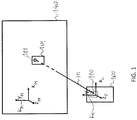
- FIG. 1 illustrates the coordinate systems used in the method of the present invention.
- a real camera device 100 has a Cartesian coordinate system K C having mutually orthogonal axes x C , y C and z C .
- the real camera device 100 comprises a real camera 110.
- the real camera device 100 may be any kind of processor-based device equipped with a camera or any sort of image sensor.
- the camera device 100 may include, for example, a mobile phone, a smart phone, a phablet, a tablet PC, a notebook, a digital camera, or the like, or any kind of other camera device capable for capturing an image.
- a planar mirror 140 also has a Cartesian coordinate system K M having mutually orthogonal axes x M , y M and z M , wherein axes x M and y M , and therefore the origo g of the coordinate system K M are all in the plane of the mirror 140.
- the real camera device 100 has a mirror view, called a virtual camera device 101 appearing behind the mirror.
- the virtual camera device 101 also has a virtual camera 111, which is a mirror view of the real camera 110.
- a vector m is defined to be perpendicular to the mirror 140 and to have a length which is equal to the distance between the mirror 140 and the real camera 110.
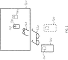
- calibration is based on the camera-mirror setup shown in Figure 2 .
- the real camera 110 captures multiple (at least two) images, each captured image showing only a mirror view (virtual object) 121 of a real object 120 and the virtual camera 111.
- the real object 120 can be within the field of view of the real camera 110 partly or entirely, it has no importance regarding the calibration procedure as only the points of the virtual objects are processed in the method of the invention according to its first aspect. It means that the real object may either be placed in a space volume between the real camera 100 and the mirror 140, or at a location that is farther from the mirror 140 than from the camera 100. In this latter case, the captured images do not contain the views of the real object 120 at all.
- the real camera device 100 has its camera 110 on its side facing the mirror 140 therefore the real camera 110 is depicted by dotted line in those Figures.
- two images I1 and I2 are shown for example, each one being captured at different camera positions.
- the virtual camera device has two pictures D1, D2, respectively, at different positions
- the virtual camera has two pictures C1, C2, respectively, at different positions
- the mirror view of the object i.e. the virtual object
- O1, 02 respectively, also at different positions.
- all of the images are preferably taken at different camera positions, while the relative position between the object and the mirror is assumed to be constant (in case of a stationary arrangement) or substantially constant (in case of a moving arrangement). If the images I1 and I2 are captured by two cameras simultaneously, the scene does not need to be stationary.
- step S200 at least two images are obtained using the aforementioned camera-mirror setup as shown in Figure 2 .
- Each of the images contains a mirror view of the real camera (i.e. the virtual camera) and a mirror view of an object.
- the image processing part of the method has the following four phases:
- the center of the pictures C1, C2 of the virtual cameras is first found in each of the images in step S206.
- M R t 0 0 0 1
- M is a complete homogenous transformation matrix
- R is a 3x3 rotation matrix
- t is a 3x1 translation vector
- n m ⁇ m ⁇
- m the vector pointing from the mirror to the camera and orthogonal to the mirror's plane. Consequently, ⁇ m ⁇ defines the distance between the mirror and the camera.
- the projection of the global vector u * onto the mirror's plane will result in an up-vector u of the mirror coordinate system K M .
- step S210 the distance between the mirror and the camera, i.e. the value of ⁇ m ⁇ is determined by calculating the aspect ratio of the camera in the image. To this end, the capturing focal length f of the camera is to be previously obtained in step S208.
- the focal length f of the camera is either a constant value and thus specified by the manufacturer of the camera or it is set by the user when capturing the images. In both cases, the focal length f of the camera is therefore assumed to be known.
- the above mentioned aspect ratio of the camera is defined as the ratio of the distance d u 1 , u 2 to the distance d U 1 , U 2 , wherein d u 1 , u 2 is the distance between two points u 1 , u 2 of the real camera device 100 and the d U 1 , U 2 is the distance between the respective points U 1 , U 2 of the picture of the virtual camera device (e.g. D1 in Figure 3 ).
- the distance is measured in the captured image in pixels, whereas the distance d U 1 , U 2 can be measured on the real camera device physically, for example in millimetre.
- a relative focal length H is to be obtained for the calculation of the vector m.
- Q be a point in the (either real or virtual) space and let p denote a respective pixel in the captured image.
- the pixel size s is a camera-specific parameter given by the manufacturer of the camera. Its value is typically about 1 micron.
- step S214 an up-vector u is defined for the mirror coordinate system K M in the following way.
- u * be any vector in the space.
- a possible selection for u * may be the gravity vector.
- Another option may be to select two points in the space with known distance from the mirror's plane. In this latter case one need to be able to find the corresponding pixels in the captured images. In fact it is not necessary to actually know this vector, it is only needed to know (or to calculate) its projection to the mirror plane, which vector is denoted by u.
- This projected vector u is regarded as the up-vector of the mirror coordinate system.
- the up-vector allows to define a coordinate transformation M** from the camera coordinate system to the mirror coordinate system in a more determined way, through setting the second column of the rotation matrix R to u. It is noted that at this point the rotation matrix R is entirely defined since the third column is the normalized mirror normal vector and the first column can be acquired from the principle of orthonormality.
- step S216 the origo of the mirror coordinate system K** M is determined. This can be done in several ways which will be introduced hereinafter.
- the origo of the mirror coordinate system is obtained by means of the free selection of a point in the space. Top this end, it is assumed that there is a point p at a known d distance from the mirror and this point is visible each of the at least one captured images. For example, this point may be selected as a mark on the mirror itself.
- the origo of the mirror coordinate system is considered to be the projection of this point p to the mirror's plane. Let the image pixel coordinates of the selected point p in the k-th image be p x k p y k , and let its distance from the mirror be d. Let g k be the base vector of the image ray.
- a second possible way of determining the origo of the mirror coordinate system is to select an arbitrary point in the mirror plane (e.g. the projection of the focal point of the camera), finding the associated image point in one of the captured images, and then finding a few further corresponding points in at least one other captured image.
- the origo of the mirror coordinate system can then be calculated by means of an optimization method (e.g. least mean square or the generalized Hough transform). It is noted that in this scheme, more than one associated point pair is needed for the calculations.
- a third possible way of determining the origo of the mirror coordinate system is to capture images I4, I5 by using two camera devices simultaneously in such a way that at least one of the images (without loss of generality let this be image 14) includes the pictures D1, D2' of the mirror views of both camera devices, while the other image (e.g. image 15) includes only the picture D2 of the mirror view of the second camera, as shown in Figure 9 .
- the images 14, I5 also show the pictures O1, 02 of the mirror view of an object.
- the projected points of the focal points of the cameras on the images are also known.
- the projected focal point of D2 be the common origo. Since the distance of D2 from the mirror and the pixel position of this point in image I4 is known, the translation to the common origo (the projection of D2 to the mirror plane) can be easily calculated for the first image.
- the coordinate transformation from the coordinate system of the image capturing camera into the mirror coordinate system is determined for each image in step S218.
- the advantage of the above described calibration method is that the coordinate transformation matrices M can be determined for each captured image separately, thus the calculation of the fundamental matrix F requires less computational force than in other known methods.
- the fundamental matrix F can be visualized by epipolar lines as shown in Figure 5 , in which the dashed lines of images I1 and I2 with the same letter are mutually corresponding epipolar lines. Accordingly, the corresponding epipolar line pairs in image I1 and image 12 are lines a1 and a2, respectively; lines b1 and b2, respectively; and lines c1 and c2, respectively. It means that any point in one of the images I1, I2 should belong to a real 3D point that has its picture on the other one of the images I1, I2 along the corresponding epipolar line (assuming that the mentioned point is not masked in the other images).
- the multiple views of the object is included within one image, wherein one of the views of the object is the picture of the real object and the other view of the object is its mirror view.
- the image shall also contain the mirror view of the capturing camera.
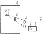
- calibration is based on the camera-mirror setup shown in Figure 6 .
- the real camera 110 captures both of the view and the mirror view of an object 120.
- the mirror view of the capturing camera device 100 with its camera 110 i.e. the virtual camera device 101 with its virtual camera 111
- the real object 120 shall be within the field of view of the real camera 110 at least partly.
- the real camera device 100 has its camera 110 on its side facing the mirror 140 therefore the real camera 110 is depicted by dotted line.
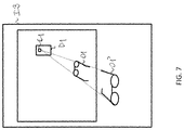
- FIG 7 an image 13 captured in the camera-mirror setup of Figure 6 is shown for example.
- the virtual camera device has a pictures D1
- the virtual camera has a picture C1
- the real object and the mirror view of the object i.e. the virtual object
- step S300 one image is obtained using the aforementioned camera-mirror setup as shown in Figure 6 .
- the captured image contains a picture of the mirror view of the real camera (i.e. the virtual camera), as well as pictures of the real view and the mirror view of an object.
- the image processing part of the method according to the second aspect of the present invention requires the only image processing phase of:
- an arbitrary mirror coordinate system is enough for the calibration of the camera-mirror setup shown in Figure 6 since only one image (i.e. image 13) is captured and consequently, it is not needed to determine a specific mirror coordinate system, which in the first aspect of the present invention was used to determine the coordinate transformations between the different camera coordinate systems.
- steps S306 to S312 correspond to steps S206 to S212 of the first method, respectively.
- step S306 the center of the picture C1 of the virtual camera is found in the image, then in step S308 the capturing focal length f of the camera is obtained, followed by the step S310, in which the distance between the mirror and the camera, i.e. the value of
- the mirror plane equation is obtained in step S312 on the basis of the captured image.
- the center of the picture C1 of the virtual camera is an epipole E of the stereo system defined by the real and virtual views of the object.
- a line v that connects the epipole E with any point V1 of the picture O1 of the real object in the image I3 also contains the corresponding point V2 of the picture 02 of the virtual object.
- ⁇ 1 c ⁇ d m T p 0 .
- ⁇ 2 ⁇ c ⁇ d m T q 0 .
- the coordinate transformation from the coordinate system of the image capturing camera into an arbitrary mirror coordinate system having an origo in the mirror's plane and a z-axis parallel to a normal vector of the mirror's plane can be determined in step S316.
- the distances between these points in the real 3D space can be calculated.
- the methods of the invention allow to determine real 3D coordinates of points which appear in any one of the at least one captured image.
- the methods of the invention can be further used, for example, to measure the distance between two points of an object, which are visible in at least two different views in the at least one captured image.
- the different views of the object may include, for example, two different mirror views in two captured images (cf. first aspect of the invention), or a real view and a mirror view of the object within one image (cf. second aspect of the invention).
- a method of measuring a distance between two points of an object comprising the steps of:
- a depth estimation for a captured object may be performed to generate a depth image of the object. Furthermore, once the stereo imaging system of the invention is calibrated through the above steps, the measurement of any kind of distances between two points becomes possible by finding associated point pairs in the at least one captured image.
- a method of depth estimation for an object comprising the steps of:
- the present invention also relates to a computer program product, which includes computer-readable instructions that, when running on a computer, carry out the above steps of the method according to the first aspect of the present invention.
- the present invention also relates to a computer program product, which includes computer-readable instructions that, when running on a computer, carry out the above steps of the method according to the second aspect of the present invention.
Landscapes
- Engineering & Computer Science (AREA)
- Multimedia (AREA)
- Signal Processing (AREA)
- Physics & Mathematics (AREA)
- General Physics & Mathematics (AREA)
- Theoretical Computer Science (AREA)
- Computer Vision & Pattern Recognition (AREA)
- Geometry (AREA)
- Computer Graphics (AREA)
- Length Measuring Devices By Optical Means (AREA)
- Image Processing (AREA)
- Image Analysis (AREA)
- Stereoscopic And Panoramic Photography (AREA)
Abstract
A method is provided for calibrating a stereo imaging system by using at least one camera and a planar mirror, the method comprising the steps of:
- obtaining at least two images by means of said at least one camera, each of the images being captured from a different camera position and containing the pictures of a mirror view of the image capturing camera and a mirror view of an object, thereby obtaining multiple views of the object,
- fining the center of the picture of the image capturing camera in each of the images,
- obtaining a relative focal length of the at least one camera,
- determining an aspect ratio in each of the images from a distance between two points of the picture of the mirror view of the camera device belonging to the image capturing camera and a distance between the corresponding points of the real camera device belonging to the same image capturing camera,
- determining the mirror plane equation in the coordinate system of the at least one camera by using the aspect ratio and the relative focal length of the camera,
- defining an up-vector in the mirror's plane,
- selecting a reference point in the mirror's plane as the origo of the mirror coordinate system,
- for each image, separately determining the coordinate transformation from the coordinate system of the image capturing camera into the mirror coordinate system, and
- for any pair of images, determining the coordinate transformation from the coordinate system of the camera capturing one image of said image pair into the coordinate system of the camera capturing the other image of said image pair.
Description
- The invention generally relates to the production of calibrated stereo images. More particularly, the present invention relates to methods of producing calibrated stereo images by using a planar mirror and computer program products to carry out the methods.
- The distance between a camera and a spatial point in a scene can be determined or well estimated from the position of the point within two or more associated images showing the same point, wherein either the scene is stationary or the associated images are captured simultaneously. The distance calculation is still possible if one or more planar mirrors are arranged in the scene, and some of the images are captured in the mirror. The three dimensional (3D) position of a point can be computed from basic geometric relationships when the relationship between the spatial position of the image recording device and the spatial position and specific parameters of the reflecting surfaces (e.g. mirrors) are known. The challenge in computing an unknown distance from multiple images using reflecting surfaces is called catadioptric stereo vision. In J. Gluckman and S.K. Nayar: Catadioptric Stereo Using Planar Mirrors (International Journal on Computer Vision, 44(1), pp. 65-79, Aug 2001), the basic theory of catadioptric stereo image generation is described in detail. In this paper an image capturing setup including one camera and one planar mirror is introduced with a known relative position of the camera and the mirror, and hence calibration is not needed This method results in a volumetric 3D representation of an object in the real camera's view.
- In the paper of Hu et al. 'Multiple-view 3-D Reconstruction Using a Mirror' (ftp://ftp.cs.rochester.edu/pub/papers/robotics/05.tr863.Multiple-view_3-d_reconstruction_using_a_mirror.pdf) a stationary camera and a planar mirror are used for multiple-view three dimensional object reconstruction. The distance between the mirror and the camera is obtained by a single object point and a pair of points of the mirrored view of the object. The mirror image of the camera is searched in the captured images and then the epipoles of the virtual camera are used to determine the spatial relationship between the virtual camera and the real camera. This method, however, cannot be used for 3D object reconstruction if the real object is not visible in the captured images.
- The paper of Kumar et al., 'Simple calibration of non-overlapping cameras with a mirror' (http://frahm.web.unc.edu/files/2014/01/Simple-Calibration-of-Non-overlapping-Cameras-with-a-Mirror.pdf), introduces a calibration method for set of cameras. Although this method also uses the mirror images of the cameras, it does not use the images of the real object, and therefore at least five images are required in order to recover the real camera position and orientation.
- Calibrating a stereo (or multi-view) camera system is a difficult task. In general, it requires to find several corresponding points in the captured images, and then to solve a non-linear optimization problem with six to eight parameters (depending on whether or not the focal lengths of the cameras are known). In our proposed method, calibration can be obtained by reducing the aforementioned optimization problem to two independent, much simpler optimization problems, each having three or four parameters (depending on whether or not the focal lengths are known). Due to this decomposition of a more complex computation into two simpler computations, the method of the invention is faster, more reliable and more robust than the prior art calibration methods.
- The key idea of the calibration methods of the present invention is that by using the mirror view of the real camera along with multiple (different) views of an object in one or more captured images, the 3D coordinates of a point in the real space with respect to the mirror coordinate system can be easily determined. Additionally, by selecting two spatial points which both appear in the one or more captured images, the real distance between the two points can be determined on the basis of their corresponding image points.
- In a first aspect of the present invention, it is provided a method for calibrating a stereo imaging system by using at least one camera and a planar mirror, the method comprising the steps of:
- obtaining at least two images by means of said at least one camera, each of the images being captured from a different camera position and containing the pictures of a mirror view of the image capturing camera and a mirror view of an object, thereby obtaining multiple views of the object,
- finding the center of the picture of the image capturing camera in each of the images,
- obtaining a relative focal length of the at least one camera,
- determining an aspect ratio in each of the images from a distance between two points of the picture of the mirror view of the camera device belonging to the image capturing camera and a distance between the corresponding points of the real camera device belonging to the same image capturing camera,
- determining the mirror plane equation in the coordinate system of the at least one camera by using the aspect ratio and the relative focal length of the camera,
- defining an up-vector in the mirror's plane,
- selecting a reference point in the mirror's plane as the origo of the mirror coordinate system,
- for each image, separately determining the coordinate transformation from the coordinate system of the image capturing camera into the mirror coordinate system, and
- for any pair of images, determining the coordinate transformation from the coordinate system of the camera capturing one image of said image pair into the coordinate system of the camera capturing the other image of said image pair.
- The up-vector may be obtained by projecting a gravity vector on the mirror's plane or by selecting corresponding point pairs in the at least one image.
- In a second aspect of the present invention, it is provided a method for calibrating a stereo imaging system by using one camera and a planar mirror, the method comprising the steps of:
- obtaining one image captured by the camera, said image containing the pictures of a real view and a mirror view of the object and a mirror view of the image capturing camera, thereby obtaining multiple views of the object,
- finding the center of the picture of the image capturing camera in the image,
- obtaining a relative focal length of the camera,
- determining an aspect ratio in the image from a distance between two points of the picture of the mirror view of the camera device and a distance between the corresponding points of the real camera device,
- determining the mirror plane equation in the coordinate system of the camera by using the aspect ratio and the relative focal length of the camera,
- determining the real coordinates of the epipole of the image,
- determining the coordinate transformation from the coordinate system of the image capturing camera into an arbitrary mirror coordinate system having an origo in the mirror's plane and a z-axis parallel to a normal vector of the mirror's plane.
- In a particularly preferred embodiment of the above methods, the camera is part of a camera device including any one of a mobile phone, a smart phone, a phablet, a tablet computer, a notebook, a digital camera or the like.
- In a third aspect of the invention, it is provided a method of measuring a distance between two points of an object, wherein the method comprises the steps of:
- capturing at least one image with multiple views of said object by means of a camera-mirror setup including at least one camera and a planar mirror,
- calibrating said camera-mirror setup through the steps of the method according to any one of the first and second aspect of the invention,
- finding an associated point pair in an image view of the object in one of the at least one captured image, and
- calculating the real distance between the two selected points of the object on the basis of acquiring real 3D points from corresponding pixel pairs using the epipolar geometry.
- In a fourth aspect of the invention, it is provided a method of depth estimation for an object, wherein the method comprises the steps of:
- capturing at least one image with multiple views of said object by means of a camera-mirror setup including at least one camera and a planar mirror,
- calibrating said camera-mirror setup through the steps of the method according to any one of the first and second aspect of the invention, and
- generating a depth image of the object from the at least one captured image.
- In a fifth aspect of the invention, it is provided a computer program product, which includes computer-readable instructions that, when running on a computer, carry out the steps of the method according to the first aspect of the present invention.
- In a sixth aspect of the invention, it is provided a computer program product, which includes computer-readable instructions that, when running on a computer, carry out the steps of the method according to the second aspect of the present invention.
- The invention will now be described in detail through preferred embodiments with reference to the accompanying drawings wherein:
-
Figure 1 schematically illustrates the coordinate systems and the geometry of the methods of the present invention. -
Figure 2 schematically illustrates the camera-mirror setup according to a first aspect of the present invention. -
Figure 3 shows two images captured by a camera at different positions in the camera-mirror setup ofFigure 2 . -
Figure 4 is a flow diagram of the major steps of the calibration method according to the first aspect of the present invention. -
Figure 5 illustrates the images ofFigure 3 with epipolar lines. -
Figure 6 schematically illustrates the camera-mirror setup according to a second aspect of the present invention. -
Figure 7 shows an image captured by the camera in the camera-mirror setup ofFigure 6 . -
Figure 8 is a flow diagram of the major steps of the calibration method according to the second aspect of the present invention. -
Figure 9 shows a further pair of exemplary images simultaneously captured by two cameras at different positions in the camera-mirror setup according to the first aspect of the present invention. - Within the context of the present description, the term "image" means the product of image capturing performed by an image recording device, such as an image sensor or a camera, while the term "picture" means a visual representation of an object or person within a captured image. An image may be a still image or a frame of a video sequence (also referred to as video image).
-
Figure 1 illustrates the coordinate systems used in the method of the present invention. Areal camera device 100 has a Cartesian coordinate system KC having mutually orthogonal axes xC, yC and zC. Thereal camera device 100 comprises areal camera 110. Thereal camera device 100 may be any kind of processor-based device equipped with a camera or any sort of image sensor. Thecamera device 100 may include, for example, a mobile phone, a smart phone, a phablet, a tablet PC, a notebook, a digital camera, or the like, or any kind of other camera device capable for capturing an image. - A
planar mirror 140 also has a Cartesian coordinate system KM having mutually orthogonal axes xM, yM and zM, wherein axes xM and yM, and therefore the origo g of the coordinate system KM are all in the plane of themirror 140. Thereal camera device 100 has a mirror view, called avirtual camera device 101 appearing behind the mirror. Thevirtual camera device 101 also has a virtual camera 111, which is a mirror view of thereal camera 110. - A vector m is defined to be perpendicular to the
mirror 140 and to have a length which is equal to the distance between themirror 140 and thereal camera 110. One can calculate the vector m using the point of themirror 140 where the virtual camera 111 appears as it will be described later. - According to a first aspect of the present invention, calibration is based on the camera-mirror setup shown in
Figure 2 . In this setup thereal camera 110 captures multiple (at least two) images, each captured image showing only a mirror view (virtual object) 121 of areal object 120 and the virtual camera 111. Although thereal object 120 can be within the field of view of thereal camera 110 partly or entirely, it has no importance regarding the calibration procedure as only the points of the virtual objects are processed in the method of the invention according to its first aspect. It means that the real object may either be placed in a space volume between thereal camera 100 and themirror 140, or at a location that is farther from themirror 140 than from thecamera 100. In this latter case, the captured images do not contain the views of thereal object 120 at all. - It is noted that in
Figures 1 and2 , thereal camera device 100 has itscamera 110 on its side facing themirror 140 therefore thereal camera 110 is depicted by dotted line in those Figures. - In
Figure 3 , two images I1 and I2 are shown for example, each one being captured at different camera positions. In the images I1 and I2, the virtual camera device has two pictures D1, D2, respectively, at different positions, the virtual camera has two pictures C1, C2, respectively, at different positions, and the mirror view of the object (i.e. the virtual object) has also two pictures O1, 02, respectively, also at different positions. In case more than two images are captured, all of the images are preferably taken at different camera positions, while the relative position between the object and the mirror is assumed to be constant (in case of a stationary arrangement) or substantially constant (in case of a moving arrangement). If the images I1 and I2 are captured by two cameras simultaneously, the scene does not need to be stationary. - The main steps of the calibration method of the present invention according to its first aspect are shown by the flow diagram of
Figure 4 . - In step S200 at least two images are obtained using the aforementioned camera-mirror setup as shown in
Figure 2 . Each of the images contains a mirror view of the real camera (i.e. the virtual camera) and a mirror view of an object. - The image processing part of the method has the following four phases:
- A) Determining a coordinate transformation M*1 from a first camera coordinate system KC1 to an arbitrary mirror coordinate system K*M1 by using a first image, and determining a coordinate transformation M*2 from a second camera coordinate system KC2 to the another arbitrary mirror coordinate system K*M2 by using a second image. The mirror coordinate systems K*M1 and K*M2 are selected so that their origo locates in the mirror's plane and their z-axis is parallel to a normal vector of the mirror's plane.
- B) Using a freely selected global vector, a so called up-vector, that can be detected in relation to all of the initial images, one can define a common y-axis of these mirror coordinate systems K*M1 and K*M2, and hence the transformations M**1 and M**2 from the first and second camera coordinate systems KC1, KC2 to the mirror coordinate system K**M1 and K**M2, respectively.
- C) Determining a global origo g and find the coordinates of this origo g in the mirror coordinate systems K**M1, and K**M2, thereby obtaining a specific mirror coordinate system KM, and then determining the coordinate transformations M1 and M2 from the first and second camera coordinate systems KC1, KC2, respectively, to the common mirror coordinate system KM.
- D) Determining a coordinate transformation F from any camera coordinate system KCk to the first camera coordinate system KC1 by determining the coordinate transformation Mk with respect to a further image Ik , wherein

- The above phases of the calibration method of the present inventions will be now described in detail with reference to
Figure 4 and also toFigure 2 , which illustrates two captured images as an example. It noted that the images I1 and I2 shown inFigure 2 may be recorded either the same camera device subsequently, or by different camera device simultaneously. In the latter case the pictures D1 and D2 belong to different camera devices. - In order to determine a coordinate transformation from a camera coordination system to an arbitrary mirror coordination system, the center of the pictures C1, C2 of the virtual cameras is first found in each of the images in step S206.
- In the calculations we assume that the coordinate transformations have the following general form:

- To calculate the rotation matrix R, first the z-axis of the camera is to be transformed to the normal vector n of the mirror plane. The normal vector is

- The rotation matrix R should transform the y-axis of the camera to the projection of the same global vector to the mirror plane. Hence, it is necessary to define a vector u that is common to all captured images. Based on said vector u, the rotation matrix may be defined as:

- In the camera coordinate system, the mirror plane can be formulated as:

- Note that there exist numerous possible transformations M* from the particular camera coordinate system to an arbitrary mirror coordinate system K*M, since the mirror coordinate system is not completely specified at this stage. The only restrictions for the mirror coordinate system are that the third column of the rotation matrix R in the coordinate transformation M* should be


- In step S210, the distance between the mirror and the camera, i.e. the value of ∥m∥ is determined by calculating the aspect ratio of the camera in the image. To this end, the capturing focal length f of the camera is to be previously obtained in step S208.
- The focal length f of the camera is either a constant value and thus specified by the manufacturer of the camera or it is set by the user when capturing the images. In both cases, the focal length f of the camera is therefore assumed to be known.
- The above mentioned aspect ratio of the camera is defined as the ratio of the distance d u
1 ,u2 to the distance d U1 , U2 , wherein d u1 , u2 is the distance between two points u1, u2 of thereal camera device 100 and the d U1 ,U2 is the distance between the respective points U1, U2 of the picture of the virtual camera device (e.g. D1 inFigure 3 ). The distance is measured in the captured image in pixels, whereas the distance d U1 ,U2 can be measured on the real camera device physically, for example in millimetre. - Next, a relative focal length H is to be obtained for the calculation of the vector m. To obtain it, let Q be a point in the (either real or virtual) space and let p denote a respective pixel in the captured image. The pixel coordinates px ,py of the point p in the image may be defined in the camera coordinate system by the equations:

- For making the following calculations easier, a relative focal length H is defined as the ratio of the focal length f and the pixel size s:

- Accordingly, the mirror's normal vector m can be calculated by the following expression:

- As a result, the mirror plane equation can be obtained in step S212 according to the above mentioned formula:

- Next, in step S214, an up-vector u is defined for the mirror coordinate system KM in the following way.
- Let u* be any vector in the space. A possible selection for u* may be the gravity vector. Another option may be to select two points in the space with known distance from the mirror's plane. In this latter case one need to be able to find the corresponding pixels in the captured images. In fact it is not necessary to actually know this vector, it is only needed to know (or to calculate) its projection to the mirror plane, which vector is denoted by u. This projected vector u is regarded as the up-vector of the mirror coordinate system. The up-vector allows to define a coordinate transformation M** from the camera coordinate system to the mirror coordinate system in a more determined way, through setting the second column of the rotation matrix R to u. It is noted that at this point the rotation matrix R is entirely defined since the third column is the normalized mirror normal vector and the first column can be acquired from the principle of orthonormality.
- In step S216, the origo of the mirror coordinate system K**M is determined. This can be done in several ways which will be introduced hereinafter.
- In a first possible way, the origo of the mirror coordinate system is obtained by means of the free selection of a point in the space. Top this end, it is assumed that there is a point p at a known d distance from the mirror and this point is visible each of the at least one captured images. For example, this point may be selected as a mark on the mirror itself. The origo of the mirror coordinate system is considered to be the projection of this point p to the mirror's plane. Let the image pixel coordinates of the selected point p in the k-th image be


- The 3D real coordinates p = µgk can be easily calculated in the camera coordinate system by noting that it is the cross point of a multiple of the ray vector and the translation of the mirror plane by d, that is

- As a result gk can be calculated by finding a multiplication factor µ for which:

- From the above equation the 3D coordinates of point p in the camera coordinate system is:

- The origo of the mirror coordinate system can be obtained by adding a vector of length d and the direction of the mirror plane normal to p, resulting in the following expression:

- A second possible way of determining the origo of the mirror coordinate system is to select an arbitrary point in the mirror plane (e.g. the projection of the focal point of the camera), finding the associated image point in one of the captured images, and then finding a few further corresponding points in at least one other captured image. The origo of the mirror coordinate system can then be calculated by means of an optimization method (e.g. least mean square or the generalized Hough transform). It is noted that in this scheme, more than one associated point pair is needed for the calculations. The optimization problem comes straightforwardly from the above equations. Let us assume that there are some corresponding pixels in the images


- It is noted that the distance of these points from the mirror's plane is unknown. Let us denote these distance by dk. This results in the following set of equations:

- A third possible way of determining the origo of the mirror coordinate system is to capture images I4, I5 by using two camera devices simultaneously in such a way that at least one of the images (without loss of generality let this be image 14) includes the pictures D1, D2' of the mirror views of both camera devices, while the other image (e.g. image 15) includes only the picture D2 of the mirror view of the second camera, as shown in
Figure 9 . The images 14, I5 also show the pictures O1, 02 of the mirror view of an object. It is noted that once the mirror plane equation is known in both camera coordinate systems, the real distance between the camera devices and the mirror is also known. Furthermore the projected points of the focal points of the cameras on the images are also known. In the above described scheme the projected focal point of D2 be the common origo. Since the distance of D2 from the mirror and the pixel position of this point in image I4 is known, the translation to the common origo (the projection of D2 to the mirror plane) can be easily calculated for the first image. - Based on the above calculations and considerations, the coordinate transformation from the coordinate system of the image capturing camera into the mirror coordinate system is determined for each image in step S218.
- Hence, in step S220, a coordinate transformation between any two camera coordinate systems can be carried out by using the above mentioned fundamental matrix:

- The fundamental matrix F can be visualized by epipolar lines as shown in
Figure 5 , in which the dashed lines of images I1 and I2 with the same letter are mutually corresponding epipolar lines. Accordingly, the corresponding epipolar line pairs in image I1 and image 12 are lines a1 and a2, respectively; lines b1 and b2, respectively; and lines c1 and c2, respectively. It means that any point in one of the images I1, I2 should belong to a real 3D point that has its picture on the other one of the images I1, I2 along the corresponding epipolar line (assuming that the mentioned point is not masked in the other images). - In a second aspect of the present invention, the multiple views of the object is included within one image, wherein one of the views of the object is the picture of the real object and the other view of the object is its mirror view. The image shall also contain the mirror view of the capturing camera.
- According to the second aspect of the present invention, calibration is based on the camera-mirror setup shown in
Figure 6 . In this setup thereal camera 110 captures both of the view and the mirror view of anobject 120. The mirror view of the capturingcamera device 100 with its camera 110 (i.e. thevirtual camera device 101 with its virtual camera 111) is also appearing in themirror 140. In this case, thereal object 120 shall be within the field of view of thereal camera 110 at least partly. - It is noted that in
Figure 6 , thereal camera device 100 has itscamera 110 on its side facing themirror 140 therefore thereal camera 110 is depicted by dotted line. - In
Figure 7 , an image 13 captured in the camera-mirror setup ofFigure 6 is shown for example. In the image I3, the virtual camera device has a pictures D1, the virtual camera has a picture C1, and the real object and the mirror view of the object (i.e. the virtual object) have two pictures O1, O1', respectively, at different positions within the image I3. - The main steps of the calibration method of the present invention according to its second aspect is shown by the flow diagram of
Figure 8 . - In step S300 one image is obtained using the aforementioned camera-mirror setup as shown in
Figure 6 . The captured image contains a picture of the mirror view of the real camera (i.e. the virtual camera), as well as pictures of the real view and the mirror view of an object. - The image processing part of the method according to the second aspect of the present invention requires the only image processing phase of:
- A) Determining a coordinate transformation M* from the camera coordinate system KC to an arbitrary mirror coordinate system K*M by using the image. The mirror coordinate system K*M is selected so that its origo locates in the mirror's plane and its z-axis is parallel to a normal vector of the mirror's plane.
- It is noted that in this aspect of the present invention, an arbitrary mirror coordinate system is enough for the calibration of the camera-mirror setup shown in
Figure 6 since only one image (i.e. image 13) is captured and consequently, it is not needed to determine a specific mirror coordinate system, which in the first aspect of the present invention was used to determine the coordinate transformations between the different camera coordinate systems. - The above phase A) of the image processing is carried out in the same way as in the first aspect, with the difference that only one coordinate transformation is determined between the camera coordinate system and the mirror coordinate system (which may have its origo anywhere in the mirror's plane and its up-vector extending in any direction within the mirror's plane). Accordingly, steps S306 to S312 correspond to steps S206 to S212 of the first method, respectively. In particular, in step S306, the center of the picture C1 of the virtual camera is found in the image, then in step S308 the capturing focal length f of the camera is obtained, followed by the step S310, in which the distance between the mirror and the camera, i.e. the value of ||m||, is determined by calculating the aspect ratio of the camera in the image. As a result, the mirror plane equation is obtained in step S312 on the basis of the captured image.
- In this case the center of the picture C1 of the virtual camera is an epipole E of the stereo system defined by the real and virtual views of the object. This means that a line v that connects the epipole E with any point V1 of the picture O1 of the real object in the image I3 also contains the corresponding point V2 of the
picture 02 of the virtual object. By finding these points V1, V2 in the image I3, the position of the point in the real three dimensional space can be determined in step S314. In this regard let us assume that the pixel coordinates of a point and the mirror view of that point (i.e. the virtual point) are both known, while only the distance between said point and the mirror is unknown. In this case there are two specific constraints, namely: - 1. The distance between the point and the mirror's plane equals to the distance between the virtual point and the mirror.
- 2. The vector that connects the real point and the virtual point is perpendicular to the mirror's plane (and therefore it is also parallel to the normal vector of the mirror's plane).
- From the above two conditions the distance between the point and the mirror can be simply calculated as described below.
- Let (ux,uy ) be the coordinates of the picture u of a real point p in a captured image and (vx,vy ) be the coordinates of the picture v of the mirror view q of the point p within the same image. Once the distance c between the point p and the mirror is determined, the 3D coordinates of the real point p in the camera coordinate system can be easily calculated using the equations as described above.
- Let µ 1 and µ 2 be selected in a way that


- Hence,


- Furthermore it is known that the differential vector p - q is parallel to the vector m, hence p - q = τm. Substituting µ 1 and µ 2 leads to a simple linear equation system for c and τ. By salving the equation system, the 3D coordinates of the point p can be calculated.
- Based on the above calculations and considerations, the coordinate transformation from the coordinate system of the image capturing camera into an arbitrary mirror coordinate system having an origo in the mirror's plane and a z-axis parallel to a normal vector of the mirror's plane can be determined in step S316.
- Upon calculating the positions of further associated point pairs in the image, the distances between these points in the real 3D space can be calculated.
- The methods of the invention allow to determine real 3D coordinates of points which appear in any one of the at least one captured image. Thus the methods of the invention can be further used, for example, to measure the distance between two points of an object, which are visible in at least two different views in the at least one captured image. The different views of the object may include, for example, two different mirror views in two captured images (cf. first aspect of the invention), or a real view and a mirror view of the object within one image (cf. second aspect of the invention).
- Accordingly, in a third aspect of the invention, it is provided a method of measuring a distance between two points of an object, wherein the method comprises the steps of:
- capturing at least one image with multiple views of said object by means of a camera-mirror setup including at least one camera and a planar mirror,
- calibrating said camera-mirror setup through the steps of the method according to the first any one of the first and second aspects of the invention,
- finding an associated point pair in an image view of the object in one of the at least one captured image, and
- calculating the real distance between the two selected points of the object on the basis of acquiring real 3D points from corresponding pixel pairs using the epipolar geometry.
- Once a stereo imaging system described above is calibrated by means of the above steps, a depth estimation for a captured object may be performed to generate a depth image of the object. Furthermore, once the stereo imaging system of the invention is calibrated through the above steps, the measurement of any kind of distances between two points becomes possible by finding associated point pairs in the at least one captured image.
- Accordingly, in a fourth aspect of the invention, it is provided a method of depth estimation for an object, wherein the method comprises the steps of:
- capturing at least one image with multiple views of said object by means of a camera-mirror setup including at least one camera and a planar mirror,
- calibrating said camera-mirror setup through the steps of the method of any one of the first and second aspects of the invention, and
- generating a depth image of the object from the at least one captured image.
- In a fifth aspect, the present invention also relates to a computer program product, which includes computer-readable instructions that, when running on a computer, carry out the above steps of the method according to the first aspect of the present invention.
- In a sixth aspect, the present invention also relates to a computer program product, which includes computer-readable instructions that, when running on a computer, carry out the above steps of the method according to the second aspect of the present invention.
Claims (7)
- A method for calibrating a stereo imaging system by using at least one camera and a planar mirror, the method comprising the steps of:- obtaining at least two images by means of said at least one camera (S200), each of the images being captured from a different camera position and containing the pictures of a mirror view of the image capturing camera and a mirror view of an object, thereby obtaining multiple views of the object,- finding the center of the picture of the image capturing camera in each of the images (S206),- obtaining a relative focal length of the at least one camera (S208),- determining an aspect ratio in each of the images from a distance between two points of the picture of the mirror view of the camera device belonging to the image capturing camera and a distance between the corresponding points of the real camera device belonging to the same image capturing camera (S210),- determining the mirror plane equation in the coordinate system of the at least one camera by using the aspect ratio and the relative focal length of the camera (S212),- defining an up-vector in the mirror's plane (S214),- selecting a reference point in the mirror's plane as the origo of the mirror coordinate system (S216),- for each image, separately determining the coordinate transformation from the coordinate system of the image capturing camera into the mirror coordinate system (S218), and- for any pair of images, determining the coordinate transformation from the coordinate system of the camera capturing one image of said image pair into the coordinate system of the camera capturing the other image of said image pair (S220).
- A method for calibrating a stereo imaging system by using one camera and a planar mirror, the method comprising the steps of:- obtaining one image captured by the camera (S300), said image containing the pictures of a real view and a mirror view of the object and a mirror view of the image capturing camera, thereby obtaining multiple views of the object,- finding the center of the picture of the image capturing camera in the image (S306),- obtaining a relative focal length of the camera (S308),- determining an aspect ratio in the image from a distance between two points of the picture of the mirror view of the camera device and a distance between the corresponding points of the real camera device (S310),- determining the mirror plane equation in the coordinate system of the camera by using the aspect ratio and the relative focal length of the camera (S312),- determining the real coordinates of the epipole of the image (S314),- determining the coordinate transformation from the coordinate system of the image capturing camera into an arbitrary mirror coordinate system having an origo in the mirror's plane and a z-axis parallel to a normal vector of the mirror's plane (S316).
- The method of claim 1, wherein the up-vector is obtained by projecting a gravity vector on the mirror's plane.
- The method of claim 1, wherein the up-vector is obtained by selecting corresponding point pairs in the at least one image.
- The method of claims 1 to 4, wherein the camera is part of a camera device including any one of a mobile phone, a smart phone, a phablet, a tablet computer, a notebook, a digital camera or the like.
- A computer program product, which includes computer-readable instructions that, when running on a computer, carry out the steps of method 1.
- A computer program product, which includes computer-readable instructions that, when running on a computer, carry out the steps of method 2.
Priority Applications (9)
| Application Number | Priority Date | Filing Date | Title |
|---|---|---|---|
| EP16462003.1A EP3217355A1 (en) | 2016-03-07 | 2016-03-07 | Methods and computer program products for calibrating stereo imaging systems by using a planar mirror |
| US15/074,677 US10373337B2 (en) | 2016-03-07 | 2016-03-18 | Methods and computer program products for calibrating stereo imaging systems by using a planar mirror |
| EP17713419.4A EP3427227B1 (en) | 2016-03-07 | 2017-03-07 | Methods and computer program products for calibrating stereo imaging systems by using a planar mirror |
| CN201780028130.8A CN109155070A (en) | 2016-03-07 | 2017-03-07 | Use the method and computer program product of flat mirror calibration stereo imaging system |
| JP2018547935A JP2019510311A (en) | 2016-03-07 | 2017-03-07 | Method and computer program product for calibrating a stereo imaging system using a planar mirror |
| US16/082,573 US10846885B2 (en) | 2016-03-07 | 2017-03-07 | Methods and computer program products for calibrating stereo imaging systems by using a planar mirror |
| PCT/HU2017/050006 WO2017153793A1 (en) | 2016-03-07 | 2017-03-07 | Methods and computer program products for calibrating stereo imaging systems by using a planar mirror |
| ES17713419T ES2805425T3 (en) | 2016-03-07 | 2017-03-07 | Computer program procedures and products for calibrating stereo imaging systems using a flat mirror |
| US16/448,876 US11010925B2 (en) | 2016-03-07 | 2019-06-21 | Methods and computer program products for calibrating stereo imaging systems by using a planar mirror |
Applications Claiming Priority (1)
| Application Number | Priority Date | Filing Date | Title |
|---|---|---|---|
| EP16462003.1A EP3217355A1 (en) | 2016-03-07 | 2016-03-07 | Methods and computer program products for calibrating stereo imaging systems by using a planar mirror |
Publications (1)
| Publication Number | Publication Date |
|---|---|
| EP3217355A1 true EP3217355A1 (en) | 2017-09-13 |
Family
ID=55699597
Family Applications (2)
| Application Number | Title | Priority Date | Filing Date |
|---|---|---|---|
| EP16462003.1A Withdrawn EP3217355A1 (en) | 2016-03-07 | 2016-03-07 | Methods and computer program products for calibrating stereo imaging systems by using a planar mirror |
| EP17713419.4A Not-in-force EP3427227B1 (en) | 2016-03-07 | 2017-03-07 | Methods and computer program products for calibrating stereo imaging systems by using a planar mirror |
Family Applications After (1)
| Application Number | Title | Priority Date | Filing Date |
|---|---|---|---|
| EP17713419.4A Not-in-force EP3427227B1 (en) | 2016-03-07 | 2017-03-07 | Methods and computer program products for calibrating stereo imaging systems by using a planar mirror |
Country Status (6)
| Country | Link |
|---|---|
| US (3) | US10373337B2 (en) |
| EP (2) | EP3217355A1 (en) |
| JP (1) | JP2019510311A (en) |
| CN (1) | CN109155070A (en) |
| ES (1) | ES2805425T3 (en) |
| WO (1) | WO2017153793A1 (en) |
Cited By (1)
| Publication number | Priority date | Publication date | Assignee | Title |
|---|---|---|---|---|
| CN113205555A (en) * | 2021-05-28 | 2021-08-03 | 上海扩博智能技术有限公司 | Method, system, device and storage medium for keeping blade in middle of camera visual field |
Families Citing this family (15)
| Publication number | Priority date | Publication date | Assignee | Title |
|---|---|---|---|---|
| JP2016125956A (en) * | 2015-01-07 | 2016-07-11 | ソニー株式会社 | Information processor, information processing method and information processing system |
| EP3217355A1 (en) * | 2016-03-07 | 2017-09-13 | Lateral Reality Kft. | Methods and computer program products for calibrating stereo imaging systems by using a planar mirror |
| CN109300163B (en) * | 2018-09-14 | 2021-09-24 | 高新兴科技集团股份有限公司 | Space calibration method of indoor panoramic camera, storage medium and electronic equipment |
| CN111275766B (en) * | 2018-12-05 | 2023-09-05 | 杭州海康威视数字技术股份有限公司 | Calibration method and device for image coordinate system and GPS coordinate system and camera |
| CN109886879B (en) * | 2019-02-19 | 2022-11-01 | 广东建星建造第一工程有限公司 | Image processing method, electronic device and storage medium |
| CN109934878B (en) * | 2019-03-25 | 2020-11-27 | 合肥工业大学 | Linear calibration system and method based on camera coordinate system |
| CN112180362B (en) * | 2019-07-05 | 2024-04-23 | 北京地平线机器人技术研发有限公司 | Method and device for determining conversion pose between radar and camera and electronic equipment |
| CN111028299A (en) * | 2020-02-18 | 2020-04-17 | 吴怡锦 | System and method for calculating spatial distance of calibration points based on point attribute data set in image |
| CN111369447B (en) * | 2020-03-09 | 2023-06-16 | 湖南警察学院 | Method for correcting image point in monocular stereoscopic vision image |
| US11282233B1 (en) * | 2020-09-08 | 2022-03-22 | Weta Digital Limited | Motion capture calibration |
| CN112258586B (en) * | 2020-10-16 | 2022-10-21 | 中国石油大学(华东) | Calibration method for stereoscopic vision model parameters of single plane mirror |
| US11546385B1 (en) | 2020-12-31 | 2023-01-03 | Benjamin Slotznick | Method and apparatus for self-selection by participant to display a mirrored or unmirrored video feed of the participant in a videoconferencing platform |
| US11330021B1 (en) * | 2020-12-31 | 2022-05-10 | Benjamin Slotznick | System and method of mirroring a display of multiple video feeds in videoconferencing systems |
| US11621979B1 (en) | 2020-12-31 | 2023-04-04 | Benjamin Slotznick | Method and apparatus for repositioning meeting participants within a virtual space view in an online meeting user interface based on gestures made by the meeting participants |
| CN116051647B (en) * | 2022-08-08 | 2024-06-25 | 荣耀终端有限公司 | Camera calibration method and electronic equipment |
Citations (1)
| Publication number | Priority date | Publication date | Assignee | Title |
|---|---|---|---|---|
| EP2866446A1 (en) * | 2013-10-28 | 2015-04-29 | Lateral Reality Kft. | Method and multi-camera portable device for producing stereo images |
Family Cites Families (24)
| Publication number | Priority date | Publication date | Assignee | Title |
|---|---|---|---|---|
| US8189100B2 (en) * | 2006-07-25 | 2012-05-29 | Qualcomm Incorporated | Mobile device with dual digital camera sensors and methods of using the same |
| US8929645B2 (en) * | 2007-04-24 | 2015-01-06 | 21 Ct, Inc. | Method and system for fast dense stereoscopic ranging |
| CN101796372B (en) * | 2008-07-11 | 2012-11-14 | 松下电器产业株式会社 | Three-dimensional shape measuring device, integrated circuit, and method |
| CN101577002B (en) * | 2009-06-16 | 2011-12-28 | 天津理工大学 | Calibration method of fish-eye lens imaging system applied to target detection |
| US20110007205A1 (en) * | 2009-07-08 | 2011-01-13 | Dechnia, LLC | Rear to forward facing camera adapter |
| KR101055411B1 (en) * | 2010-03-12 | 2011-08-09 | 이상원 | Method and apparatus of generating stereoscopic image |
| US8908015B2 (en) * | 2010-03-24 | 2014-12-09 | Appcessories Llc | Apparatus and method for producing images for stereoscopic viewing |
| CN101923730B (en) * | 2010-09-21 | 2012-05-02 | 北京大学 | Fisheye camera and multiple plane mirror devices-based three-dimensional reconstruction method |
| US8896667B2 (en) * | 2010-10-25 | 2014-11-25 | Aptina Imaging Corporation | Stereoscopic imaging systems with convergence control for reducing conflicts between accomodation and convergence |
| US10200671B2 (en) * | 2010-12-27 | 2019-02-05 | 3Dmedia Corporation | Primary and auxiliary image capture devices for image processing and related methods |
| US9230325B2 (en) * | 2011-08-19 | 2016-01-05 | University Of Rochester | Three-dimensional model acquisition using planar mirrors |
| EP2615580B1 (en) * | 2012-01-13 | 2016-08-17 | Softkinetic Software | Automatic scene calibration |
| CN103177442A (en) * | 2013-03-04 | 2013-06-26 | 北京邮电大学 | Calibrating method for two-dimensional laser and camera without overlapped viewing fields |
| US9749541B2 (en) * | 2013-04-16 | 2017-08-29 | Tout Inc. | Method and apparatus for displaying and recording images using multiple image capturing devices integrated into a single mobile device |
| CA2819956C (en) * | 2013-07-02 | 2022-07-12 | Guy Martin | High accuracy camera modelling and calibration method |
| US20150103146A1 (en) * | 2013-10-16 | 2015-04-16 | Qualcomm Incorporated | Conversion of at least one non-stereo camera into a stereo camera |
| KR102033309B1 (en) | 2013-10-25 | 2019-10-17 | 현대모비스 주식회사 | Apparatus and method for controlling beam forming microphones considering location of driver seat |
| US9615081B2 (en) * | 2013-10-28 | 2017-04-04 | Lateral Reality Kft. | Method and multi-camera portable device for producing stereo images |
| JP2015191186A (en) * | 2014-03-28 | 2015-11-02 | 富士通株式会社 | Stereo adapter and stereo image-capturing device |
| CN104200477B (en) * | 2014-09-11 | 2018-04-06 | 云南大学 | The method that plane catadioptric camera intrinsic parameter is solved based on space parallel circle |
| CN104284177A (en) * | 2014-10-28 | 2015-01-14 | 天津大学 | Convergence stereo image parallax control method |
| CN105321174B (en) * | 2015-09-23 | 2019-03-26 | 浙江大学 | A kind of multiple plane mirror reflection tracking clouds terrace system scaling method |
| EP3217355A1 (en) * | 2016-03-07 | 2017-09-13 | Lateral Reality Kft. | Methods and computer program products for calibrating stereo imaging systems by using a planar mirror |
| US9930320B2 (en) * | 2016-05-04 | 2018-03-27 | Apple Inc. | Resolving three dimensional spatial information using time-shared structured lighting that embeds digital communication |
-
2016
- 2016-03-07 EP EP16462003.1A patent/EP3217355A1/en not_active Withdrawn
- 2016-03-18 US US15/074,677 patent/US10373337B2/en active Active
-
2017
- 2017-03-07 CN CN201780028130.8A patent/CN109155070A/en active Pending
- 2017-03-07 EP EP17713419.4A patent/EP3427227B1/en not_active Not-in-force
- 2017-03-07 JP JP2018547935A patent/JP2019510311A/en active Pending
- 2017-03-07 US US16/082,573 patent/US10846885B2/en active Active
- 2017-03-07 ES ES17713419T patent/ES2805425T3/en active Active
- 2017-03-07 WO PCT/HU2017/050006 patent/WO2017153793A1/en active Application Filing
-
2019
- 2019-06-21 US US16/448,876 patent/US11010925B2/en active Active
Patent Citations (1)
| Publication number | Priority date | Publication date | Assignee | Title |
|---|---|---|---|---|
| EP2866446A1 (en) * | 2013-10-28 | 2015-04-29 | Lateral Reality Kft. | Method and multi-camera portable device for producing stereo images |
Non-Patent Citations (3)
| Title |
|---|
| HU ET AL., MULTIPLE-VIEW 3-D RECONSTRUCTION USING A MIRROR, Retrieved from the Internet <URL:ftp://ftp.cs.rochester.edu/pub/papers/robotics/05.tr863.Multiple-view 3-d reconstruction using a mirror.pdf> |
| J. GLUCKMAN; S.K. NAYAR: "Catadioptric Stereo Using Planar Mirrors", INTERNATIONAL JOURNAL ON COMPUTER VISION, vol. 44, no. 1, August 2001 (2001-08-01), pages 65 - 79, XP055108338, DOI: doi:10.1023/A:1011172403203 |
| RUI YU ET AL: "Real-Time Camera Pose Estimation Based on Multiple Planar Markers", IMAGE AND GRAPHICS, 2009. ICIG '09. FIFTH INTERNATIONAL CONFERENCE ON, IEEE, PISCATAWAY, NJ, USA, 20 September 2009 (2009-09-20), pages 640 - 645, XP031652834, ISBN: 978-1-4244-5237-8 * |
Cited By (2)
| Publication number | Priority date | Publication date | Assignee | Title |
|---|---|---|---|---|
| CN113205555A (en) * | 2021-05-28 | 2021-08-03 | 上海扩博智能技术有限公司 | Method, system, device and storage medium for keeping blade in middle of camera visual field |
| CN113205555B (en) * | 2021-05-28 | 2023-09-19 | 上海扩博智能技术有限公司 | Method, system, apparatus and storage medium for maintaining a blade centered in a camera field of view |
Also Published As
| Publication number | Publication date |
|---|---|
| EP3427227A1 (en) | 2019-01-16 |
| WO2017153793A1 (en) | 2017-09-14 |
| US20170256042A1 (en) | 2017-09-07 |
| US20190043221A1 (en) | 2019-02-07 |
| US10373337B2 (en) | 2019-08-06 |
| US10846885B2 (en) | 2020-11-24 |
| CN109155070A (en) | 2019-01-04 |
| US20190311497A1 (en) | 2019-10-10 |
| JP2019510311A (en) | 2019-04-11 |
| EP3427227B1 (en) | 2020-04-22 |
| US11010925B2 (en) | 2021-05-18 |
| ES2805425T3 (en) | 2021-02-12 |
Similar Documents
| Publication | Publication Date | Title |
|---|---|---|
| US11010925B2 (en) | Methods and computer program products for calibrating stereo imaging systems by using a planar mirror | |
| US9972120B2 (en) | Systems and methods for geometrically mapping two-dimensional images to three-dimensional surfaces | |
| JP2874710B2 (en) | 3D position measuring device | |
| EP2597597A2 (en) | Apparatus and method for calculating three dimensional (3D) positions of feature points | |
| US10853960B2 (en) | Stereo matching method and apparatus | |
| Liu et al. | Epipolar rectification method for a stereovision system with telecentric cameras | |
| Bergström et al. | Virtual projective shape matching in targetless CAD-based close-range photogrammetry for efficient estimation of specific deviations | |
| Lim et al. | Virtual camera rectification with geometrical approach on single-lens stereovision using a biprism | |
| JP7298687B2 (en) | Object recognition device and object recognition method | |
| Pedersini et al. | 3D area matching with arbitrary multiview geometry | |
| EP2866446B1 (en) | Method and multi-camera portable device for producing stereo images | |
| WO2020075213A1 (en) | Measurement apparatus, measurement method, and microscopic system | |
| Iqbal et al. | Real time 3D depth estimation and measurement of un-calibrated stereo and thermal images | |
| Cui et al. | Epipolar geometry for prism-based single-lens stereovision | |
| Cheng et al. | A linear approach for depth and colour camera calibration using hybrid parameters | |
| Bergamini et al. | Fundamental Matrix: Digital camera calibration and Essential Matrix parameters | |
| Godding et al. | 4D Surface matching for high-speed stereo sequences | |
| Woodward et al. | Real-time stereo vision on the visionserver framework for robot guidance | |
| Guerchouche et al. | Accurate camera calibration algorithm using a robust estimation of the perspective projection matrix | |
| Harvent et al. | Shape measurement using a new 3d-dic algorithm that preserves sharp edges | |
| Arnspang et al. | Relating scene depth to image ratios | |
| Leotta et al. | 3D Slit Scanning with Planar Constraints★ | |
| Herráez et al. | Epipolar image rectification through geometric algorithms with unknown parameters | |
| Gubbels | 3-D digital image correlation using a single color-camera | |
| Förstner et al. | Geometry and Orientation of the Image Pair |
Legal Events
| Date | Code | Title | Description |
|---|---|---|---|
| PUAI | Public reference made under article 153(3) epc to a published international application that has entered the european phase |
Free format text: ORIGINAL CODE: 0009012 |
|
| AK | Designated contracting states |
Kind code of ref document: A1 Designated state(s): AL AT BE BG CH CY CZ DE DK EE ES FI FR GB GR HR HU IE IS IT LI LT LU LV MC MK MT NL NO PL PT RO RS SE SI SK SM TR |
|
| AX | Request for extension of the european patent |
Extension state: BA ME |
|
| STAA | Information on the status of an ep patent application or granted ep patent |
Free format text: STATUS: THE APPLICATION IS DEEMED TO BE WITHDRAWN |
|
| 18D | Application deemed to be withdrawn |
Effective date: 20180314 |