EP3217147A1 - Micromechanical detection structure for a mems sensor device, in particular a mems gyroscope, with improved driving features - Google Patents
Micromechanical detection structure for a mems sensor device, in particular a mems gyroscope, with improved driving features Download PDFInfo
- Publication number
- EP3217147A1 EP3217147A1 EP16194684.3A EP16194684A EP3217147A1 EP 3217147 A1 EP3217147 A1 EP 3217147A1 EP 16194684 A EP16194684 A EP 16194684A EP 3217147 A1 EP3217147 A1 EP 3217147A1
- Authority
- EP
- European Patent Office
- Prior art keywords
- driving
- mass
- driven
- substrate
- movement
- Prior art date
- Legal status (The legal status is an assumption and is not a legal conclusion. Google has not performed a legal analysis and makes no representation as to the accuracy of the status listed.)
- Granted
Links
Images


Classifications
-
- G—PHYSICS
- G01—MEASURING; TESTING
- G01C—MEASURING DISTANCES, LEVELS OR BEARINGS; SURVEYING; NAVIGATION; GYROSCOPIC INSTRUMENTS; PHOTOGRAMMETRY OR VIDEOGRAMMETRY
- G01C19/00—Gyroscopes; Turn-sensitive devices using vibrating masses; Turn-sensitive devices without moving masses; Measuring angular rate using gyroscopic effects
- G01C19/56—Turn-sensitive devices using vibrating masses, e.g. vibratory angular rate sensors based on Coriolis forces
- G01C19/5642—Turn-sensitive devices using vibrating masses, e.g. vibratory angular rate sensors based on Coriolis forces using vibrating bars or beams
- G01C19/5656—Turn-sensitive devices using vibrating masses, e.g. vibratory angular rate sensors based on Coriolis forces using vibrating bars or beams the devices involving a micromechanical structure
-
- G—PHYSICS
- G01—MEASURING; TESTING
- G01C—MEASURING DISTANCES, LEVELS OR BEARINGS; SURVEYING; NAVIGATION; GYROSCOPIC INSTRUMENTS; PHOTOGRAMMETRY OR VIDEOGRAMMETRY
- G01C19/00—Gyroscopes; Turn-sensitive devices using vibrating masses; Turn-sensitive devices without moving masses; Measuring angular rate using gyroscopic effects
- G01C19/56—Turn-sensitive devices using vibrating masses, e.g. vibratory angular rate sensors based on Coriolis forces
- G01C19/5705—Turn-sensitive devices using vibrating masses, e.g. vibratory angular rate sensors based on Coriolis forces using masses driven in reciprocating rotary motion about an axis
- G01C19/5712—Turn-sensitive devices using vibrating masses, e.g. vibratory angular rate sensors based on Coriolis forces using masses driven in reciprocating rotary motion about an axis the devices involving a micromechanical structure
-
- G—PHYSICS
- G01—MEASURING; TESTING
- G01C—MEASURING DISTANCES, LEVELS OR BEARINGS; SURVEYING; NAVIGATION; GYROSCOPIC INSTRUMENTS; PHOTOGRAMMETRY OR VIDEOGRAMMETRY
- G01C19/00—Gyroscopes; Turn-sensitive devices using vibrating masses; Turn-sensitive devices without moving masses; Measuring angular rate using gyroscopic effects
- G01C19/56—Turn-sensitive devices using vibrating masses, e.g. vibratory angular rate sensors based on Coriolis forces
- G01C19/5642—Turn-sensitive devices using vibrating masses, e.g. vibratory angular rate sensors based on Coriolis forces using vibrating bars or beams
- G01C19/5663—Manufacturing; Trimming; Mounting; Housings
Definitions
- the present invention relates to a micromechanical detection structure for a MEMS (Micro-Electro-Mechanical System) sensor device, with improved driving features.
- MEMS Micro-Electro-Mechanical System
- the following discussion will make reference, without this implying any loss of generality, to use of the micromechanical detection structure in a MEMS gyroscope.
- micromachining techniques enable manufacturing of micromechanical structures within layers of semiconductor material, which have been deposited (for example, a polycrystalline-silicon layer) or grown (for example, an epitaxial layer) on sacrificial layers, which are removed via chemical etching.
- Inertial sensors for instance, accelerometers and gyroscopes, made with this technology are used successfully, for example, in the automotive field, in inertial navigation, or in the field of portable devices.
- MEMS gyroscopes integrated gyroscopes of semiconductor material made with MEMS technology are known, which are referred to hereinafter as MEMS gyroscopes.
- MEMS gyroscopes operate on the basis of the principle of relative accelerations, exploiting Coriolis acceleration.
- an angular velocity is applied to a mobile mass that is driven in a linear direction
- the mobile mass is subject to an apparent force, or Coriolis force, which determines a displacement thereof in a direction perpendicular to the linear driving direction and to the axis about which the angular velocity is applied.
- the mobile mass is supported above a substrate via elastic elements that enable driving thereof in the driving direction and displacement in the direction of the apparent force, which is directly proportional to the angular velocity.
- the displacement of the mobile mass may, for example, be detected via a capacitive transduction system, determining the variations of capacitance between mobile electrodes, which are fixed with respect to the mobile mass, and fixed electrodes, which are fixed with respect to the substrate.
- Figure 1 is a schematic representation of a micromechanical detection structure of a MEMS gyroscope of a known type, which is designated by 1 and is made in a die of semiconductor material, for example silicon, including a substrate 2.
- the detection structure 1 has a substantially planar configuration with main extension in a horizontal plane xy, defined by a first horizontal axis x and a second horizontal axis y, orthogonal to one another, and substantially parallel to the plane of the substrate 2, and a minor size, with respect to the aforesaid main extension, in a direction parallel to a vertical axis z, which forms, with the first and second horizontal axes x, y, a set of three orthogonal axes.
- the detection structure 1 comprises a first driving mass 4a and a second driving mass 4b, which have extension in the horizontal plane xy (purely by way of example, substantially rectangular), and are connected to respective anchorages 5a, 5b, fixed with respect to the substrate 2, by elastic anchorage elements 6a, 6b.
- the driving masses 4a, 4b are suspended over the substrate 2, parallel to the same substrate 2 in a resting condition.
- a respective set of driving electrodes 7a, 7b is associated to each driving mass 4a, 4b.
- Each set of driving electrodes 7a, 7b comprises: a respective plurality of mobile electrodes 8a, 8b, which are fixed with respect to the respective driving mass 4a, 4b and extend externally to the driving mass 4a, 4b; and a respective plurality of fixed electrodes 9a, 9b, which are fixed with respect to the substrate 2 and are comb-fingered with the mobile electrodes 8a, 8b.
- Suitable electrical biasing signals from an electronic circuit (not illustrated herein) for driving the MEMS gyroscope determine, by mutual and alternating electrostatic attraction of the electrodes, an oscillatory driving movement of the driving masses 4a, 4b in a linear driving direction, in the example along the second horizontal axis y.
- the first and second driving masses 4a, 4b are driven in opposite senses of the driving direction, as indicated by the arrows in Figure 2 described hereinafter.
- the elastic anchorage elements 6a, 6b are thus configured to be compliant with respect to this driving movement.
- the detection structure 1 further comprises a driven mass 10, arranged between the first and second driving masses 4a, 4b (in the direction of the first horizontal axis x), and connected to the driving masses 4a, 4b by elastic connection elements 11a, 11b. Also the driven mass 10 is suspended above the substrate 2, parallel thereto in the resting condition.
- the driven mass 10 has a main extension in the horizontal plane xy, for example with a rectangular shape, and centrally defines an empty space 12, the centre O of which coincides with the centroid and the centre of symmetry of the entire structure.
- a coupling unit 14 is arranged within the empty space 12, configured for elastic coupling and anchoring of the driven mass 10 to the substrate 2.
- the coupling unit 14 comprises a rigid element 15, in the example having a rectilinear extension along the first horizontal axis x, arranged at the centre of the empty space 12, elastically connected to the driven mass 10 by elastic elements (not shown), and further connected, by respective elastic connection elements 16 which have, in the example, a linear extension along the second horizontal axis y, to central anchorage elements 17.
- the coupling unit 14 is configured to enable rotation of the driven mass 10 in the plane of the sensor xy (with respect to the substrate 2) about the vertical axis z, in response to the driving movement in opposite directions of the driving masses 4a, 4b (as represented by the arrows).
- the driven mass 10 is drawn in rotation, in the example in the counterclockwise direction, by the movement of the driving masses 4a, 4b.
- a Coriolis force is generated on the driving masses 4a, 4b directed along the vertical axis z, which causes a respective rotation of the same driving masses 4a, 4b out of the plane of the sensor xy, in the example about the second horizontal axis y.
- Suitable electrodes arranged on the substrate 2, underneath the driving masses 4a, 4b enable, by capacitive coupling with the same driving masses 4a, 4b, detection of a quantity indicative of the value of the angular velocity about the first horizontal axis x (which thus constitutes a first detection axis for the MEMS gyroscope).
- a Coriolis force is generated on the driven mass 10 directed along the vertical axis z, which causes a respective rotation thereof out of the plane of the sensor xy, in the example about the first horizontal axis x.
- suitable electrodes arranged on the substrate 2, underneath the driven mass 10 enable, by capacitive coupling with the same driven mass 10, detection of a quantity indicative of the value of the angular velocity acting about the second horizontal axis y (which thus constitutes a second detection axis for the MEMS gyroscope).
- the present Applicant has found: undesirable cross-talk between detection structures during electrical testing thereof (when they are coupled to a same testing structure); vibrations induced in a corresponding package due to the driving movement; oscillations and instability of the zero level of the MEMS sensor device (the so-called ZRL - Zero-Rate Level); and moreover a non-zero sensitivity to undesirable external stresses and vibrations that lead to rotational accelerations about the vertical axis z.
- the aim of the present solution is to provide a detection structure of a MEMS sensor device, in particular of a MEMS gyroscope, having improved mechanical and electrical characteristics.
- the present solution stems from the realization, by the present Applicant, that the problems highlighted previously are in general due to a non-zero resultant of the forces and of the torques exerted by inertial effect on the substrate (and thus on the corresponding package) by the moving masses (driving masses and driven masses) at the corresponding anchorages, as a result of the driving movement.
- the present Applicant has realized that the aforesaid torque, transmitted to the substrate 2 and to the package, causes, for example, undesirable couplings with other detection structures during electrical-testing operations, or in general undesirable disturbance effects.
- a particular aspect of the present solution thus envisages, as will be described in detail, first with reference to Figure 3 , providing a detection structure, designated by 20, in which the arrangement and configuration of the driving/driven masses and of the corresponding elastic elements for coupling and anchorage to the substrate 2, as well as the direction of the corresponding driving movements, are such as to originate a substantially and ideally zero resultant of the forces and of the torques exerted on the substrate 2 at the corresponding anchorages.
- the detection structure 20 is substantially equivalent to the detection structure 1 of Figure 1 (elements that are similar are thus not described again herein and are designated by the same reference numbers), with the difference that it includes a first coupling element 22a and a second coupling element 22b, which elastically couple the driven mass 10 to the first driving mass 4a and to the second driving mass 4b, respectively.
- These coupling elements 22a, 22b are configured to generate on the substrate 2 a torque such as to substantially compensate the torque due to rotation of the driven mass 10; the resultant of the torques is thus substantially zero as a result of the driving movement.
- These coupling elements 22a, 22b cause in particular reversal of the velocity or driving direction of the driven mass 10, with respect to the traditional solution, described with reference to Figure 2 .
- Each coupling element 22a, 22b is configured to define a rigid connection element 24 having a first end connected to the driven mass 10 and a second end connected to the respective driving mass 4a, 4b, so as to define a respective hinged coupling (via respective elastic hinge elements, not illustrated herein).
- the rigid connection element 24 has a longitudinal extension, in the example along the first horizontal axis x, at rest.
- the aforesaid rigid connection element 24, which may ideally be considered as having infinite stiffness to bending, has, in an intermediate portion thereof between the driven mass 10 and the respective driving mass 4a, 4b, for example at a central portion thereof, a point of constraint to the substrate 2 (which is forced, that is, to remain substantially immobile to translation during movement of the driving masses 4a, 4b).
- the aforesaid intermediate portion is hinged to the substrate 2 of the detection structure 20 at the aforesaid point of constraint, in the example by a pair of respective anchorages 25 to which the aforesaid intermediate portion is connected via respective elastic hinge elements 26.
- the rigid connection element 24 is thus ideally hinged at the centre to the substrate 2, and, at its ends, to the driven mass 10 and to the respective driving mass 4a, 4b, consequently operating substantially as a rocker arm (or as a lever with a central fulcrum).
- the rigid connection element 24 is free to rotate in the horizontal plane xy about the central point of constraint, but not to translate. Consequently, the driving movement of the driving masses 4a, 4b in opposite senses of the driving direction (in the example, along the second horizontal axis y) leads in this case to a rotation in a clockwise direction of the driven mass 10 (i.e., in a direction opposite to that of the known solution of Figure 1 ).
- the coupling elements 22a, 22b are configured to exert on the substrate 2, at the respective central constraint, a total torque (in a counterclockwise direction, in the example) equal and opposite to the torque (in a clockwise direction, in the example) exerted on the same substrate 2 by the coupling unit 14 of the driven mass 10 at the central anchorage elements 17, due to rotation of the same driven mass 10 about the vertical axis z.
- the resultant of the forces exerted on the anchorages 5a, 5b on account of the driving movement of the driving masses 4a, 4b is substantially zero, in so far as the forces exerted by the individual driving masses 4a, 4b are substantially compensated (given that the respective driving movements are opposite to one another in the driving direction).
- both the resultant of the forces and the resultant of the torques that act on the substrate 2 are substantially zero.
- the mechanical characteristics (for example, in terms of the inertial masses and of the stiffnesses of the elastic elements) of the driven mass 10, of the driving masses 4a, 4b, and of the respective elements for coupling and anchorage to the substrate 2 are designed so as to ensure substantial equivalence, and thus mutual compensation, of the forces and torques generated in opposite directions, and substantial cancelling-out of the resultant of forces and torques acting on the substrate 2.
- each of the elastic hinge elements previously defined may comprise a respective pair of springs, which have longitudinal extension (for example, along the second horizontal axis y) and are set as prolongation of one another starting from the respective hinge point.
- the detection structure once again designated by 20, comprises a third driving mass 4c, in the example substantially rectangular, having extension in the horizontal plane xy, and connected to respective anchorages 5c, fixed with respect to the substrate 2, by respective elastic anchorage elements 6c.
- the third driving mass 4c is suspended above the substrate 2, parallel to the same substrate 2 in the resting condition.
- the third driving mass 4c is arranged between the first and second driving masses 4a, 4b along the first horizontal axis x.
- a geometrical centre O of the third driving mass 4c in this case represents the centroid and centre of symmetry of the detection structure 20.
- a respective set of driving electrodes 7c is associated to the third driving mass 4c, comprising a respective plurality of mobile electrodes 8c, fixed with respect to the same third driving mass 4c, as well as a respective plurality of fixed electrodes 9c fixed with respect to the substrate 2 and comb-fingered with the mobile electrodes 8c.
- Appropriate electrical biasing signals from the electronic circuit (not illustrated) for driving the MEMS gyroscope determine, by mutual and alternating electrostatic attraction of the electrodes, a respective driving movement of the third driving mass 4c in a linear driving direction, in the example along the second horizontal axis y.
- the first and second driving masses 4a, 4b are driven in the same sense of the driving direction, whereas the third driving mass 4c is driven in the opposite sense of the same driving direction.
- the detection structure 20 in this case comprises: a pair of driven masses (suspended above the substrate 2, parallel thereto in the resting condition), and in particular: a first driven mass, designated once again by 10, arranged between the first and third driving masses 4a, 4c (in the direction of the first horizontal axis x), and connected to the same driving masses 4a, 4c by elastic connection elements 11a, 11b (for example, of a linear type); and a second driven mass 30, arranged between the second and third driving masses 4b, 4c (in the direction of the first horizontal axis x), and connected to the same driving masses 4b, 4c by respective elastic connection elements 31a, 31b (which are also, for example, of a linear type).
- Each driven mass 10, 30 has a main extension in the horizontal plane xy, with a shape that is for example rectangular, and defines at the centre an empty space 12, 32, arranged inside which is a respective coupling unit 14, 34 configured for elastic coupling and anchorage of the respective driven mass 10, 30 to the substrate 2.
- Each coupling unit 14, 34 comprises a rigid element 15, 35 arranged at the centre of the empty space 12, 32, elastically connected to the respective driven mass 10, 30, and further elastically connected to central anchorage elements 17, 37 by respective elastic connection elements 16, 36, which have, in the example, a linear extension.
- the elastic connection elements 16 associated to the first driven mass 10 have a linear extension along the second horizontal axis y
- the elastic connection elements 36 associated to the second driven mass 30 have a linear extension along the first horizontal axis x (given that they are further configured so as to enable rotations of the same driven masses 10, 30 upon detection of respective angular velocities).
- the rigid element 15 coupled to the first driven mass 10 has a linear extension along the first horizontal axis x
- the rigid element 35 coupled to the second driven mass 30 has a linear extension along the second horizontal axis y.
- the first and second driven masses 10, 30 perform rotations in opposite directions (in the example, the first driven mass 10 in the counterclockwise direction and the second driven mass 30 in the clockwise direction) in the plane of the sensor xy, with respect to the substrate 2 and about the vertical axis z.
- the mechanical characteristics (for example, in terms of inertial masses and stiffnesses) of the driven masses 10, 30 and of the respective coupling units 14, 34 are designed to obtain the aforesaid substantial equivalence of the torques generated in opposite directions, and substantial cancelling-out of the resultant torque on the substrate 2.
- the resultant of the forces exerted on the anchorages 5a, 5b, 5c on account of the driving movement of the driving masses 4a, 4b, 4c is substantially zero, in so far as the forces exerted by the individual driving masses 4a, 4b, 4c (in a first sense of the driving direction for the first and second driving masses 4a, 4b, and in a second sense of the same driving direction for the third driving mass 4c) are substantially compensated, once again thanks to the appropriate sizing of the mechanical characteristics of the driving masses 4a, 4b and 4c and of the corresponding coupling and anchorage elastic elements.
- the detection movements are performed by the first and second driven masses 10, 30, which are able to turn, as a result of the Coriolis forces that are generated due to the driving movement, for example about the first horizontal axis x and the second horizontal axis y, respectively.
- the present solution enables provision of micromechanical detection structures, in particular for MEMS sensor devices, for example MEMS gyroscopes, with a substantially zero resultant of the forces and of the torques acting on the substrate at the anchorages of the moving masses.
- the first embodiment may, however, be more advantageous than the second embodiment ( Figure 5 ), at least in some circumstances, for example owing to the presence of a smaller number of moving masses, a better area occupation, a smaller number of elastic coupling elements, and a greater resulting simplicity of construction and greater insensitivity to manufacturing process spread.
- the detection structure 20 in a MEMS sensor device.
- Figure 7 shows schematically a sensor device 40, for example a MEMS gyroscope, comprising the detection structure 20, designed to generate at least one electrical detection quantity as a function at least one quantity of interest (for example, an angular velocity, in the case of a gyroscope); and an electronic circuit 42 (a so-called ASIC - Application-Specific Integrated Circuit), electrically coupled to the detection structure 20 and designed to supply driving and biasing electrical quantities to the detection structure 20 and further designed to process the electrical quantities detected, for example by amplification and filtering operations.
- a sensor device 40 for example a MEMS gyroscope
- the detection structure 20 designed to generate at least one electrical detection quantity as a function at least one quantity of interest (for example, an angular velocity, in the case of a gyroscope); and an electronic circuit 42 (a so-called ASIC - Application-Specific Integrated Circuit), electrically coupled to the detection structure 20 and designed to supply driving and biasing electrical quantities to the detection structure 20 and further designed to
- the detection structure 20 and the electronic circuit 42 may be made in respective dies of semiconductor material, which are housed in a same package 44, for example in a configuration where they are arranged side-by-side or vertically stacked on top of one another.
- the solution described may find advantageous application in bi-axial or tri-axial micromechanical detection structures, in MEMS gyroscopes, or also in different and further MEMS devices of an inertial type, in which it is desired to cancel out the resultant of the forces and torques acting on the substrate, or in any case to reduce them markedly, for example by at least a factor of ten.
Landscapes
- Engineering & Computer Science (AREA)
- Physics & Mathematics (AREA)
- General Physics & Mathematics (AREA)
- Radar, Positioning & Navigation (AREA)
- Remote Sensing (AREA)
- Manufacturing & Machinery (AREA)
- Gyroscopes (AREA)
Abstract
Description
- The present invention relates to a micromechanical detection structure for a MEMS (Micro-Electro-Mechanical System) sensor device, with improved driving features. In particular, the following discussion will make reference, without this implying any loss of generality, to use of the micromechanical detection structure in a MEMS gyroscope.
- As is known, micromachining techniques enable manufacturing of micromechanical structures within layers of semiconductor material, which have been deposited (for example, a polycrystalline-silicon layer) or grown (for example, an epitaxial layer) on sacrificial layers, which are removed via chemical etching.
- Inertial sensors, for instance, accelerometers and gyroscopes, made with this technology are used successfully, for example, in the automotive field, in inertial navigation, or in the field of portable devices.
- In particular, integrated gyroscopes of semiconductor material made with MEMS technology are known, which are referred to hereinafter as MEMS gyroscopes.
- These MEMS gyroscopes operate on the basis of the principle of relative accelerations, exploiting Coriolis acceleration. When an angular velocity is applied to a mobile mass that is driven in a linear direction, the mobile mass is subject to an apparent force, or Coriolis force, which determines a displacement thereof in a direction perpendicular to the linear driving direction and to the axis about which the angular velocity is applied.
- The mobile mass is supported above a substrate via elastic elements that enable driving thereof in the driving direction and displacement in the direction of the apparent force, which is directly proportional to the angular velocity.
- The displacement of the mobile mass may, for example, be detected via a capacitive transduction system, determining the variations of capacitance between mobile electrodes, which are fixed with respect to the mobile mass, and fixed electrodes, which are fixed with respect to the substrate.
-
Figure 1 is a schematic representation of a micromechanical detection structure of a MEMS gyroscope of a known type, which is designated by 1 and is made in a die of semiconductor material, for example silicon, including asubstrate 2. - The detection structure 1 has a substantially planar configuration with main extension in a horizontal plane xy, defined by a first horizontal axis x and a second horizontal axis y, orthogonal to one another, and substantially parallel to the plane of the
substrate 2, and a minor size, with respect to the aforesaid main extension, in a direction parallel to a vertical axis z, which forms, with the first and second horizontal axes x, y, a set of three orthogonal axes. - The detection structure 1 comprises a
first driving mass 4a and a second drivingmass 4b, which have extension in the horizontal plane xy (purely by way of example, substantially rectangular), and are connected torespective anchorages substrate 2, byelastic anchorage elements masses substrate 2, parallel to thesame substrate 2 in a resting condition. - A respective set of driving
electrodes mass electrodes mobile electrodes driving mass driving mass fixed electrodes substrate 2 and are comb-fingered with themobile electrodes - Suitable electrical biasing signals from an electronic circuit (not illustrated herein) for driving the MEMS gyroscope, determine, by mutual and alternating electrostatic attraction of the electrodes, an oscillatory driving movement of the
driving masses second driving masses Figure 2 described hereinafter. - The
elastic anchorage elements - The detection structure 1 further comprises a driven
mass 10, arranged between the first andsecond driving masses driving masses elastic connection elements mass 10 is suspended above thesubstrate 2, parallel thereto in the resting condition. - The driven
mass 10 has a main extension in the horizontal plane xy, for example with a rectangular shape, and centrally defines anempty space 12, the centre O of which coincides with the centroid and the centre of symmetry of the entire structure. - A
coupling unit 14 is arranged within theempty space 12, configured for elastic coupling and anchoring of the drivenmass 10 to thesubstrate 2. - In particular, the
coupling unit 14 comprises arigid element 15, in the example having a rectilinear extension along the first horizontal axis x, arranged at the centre of theempty space 12, elastically connected to the drivenmass 10 by elastic elements (not shown), and further connected, by respectiveelastic connection elements 16 which have, in the example, a linear extension along the second horizontal axis y, tocentral anchorage elements 17. - In use, and as shown schematically in
Figure 2 (where the detection structure 1 is shown once again schematically for clarity of illustration), thecoupling unit 14 is configured to enable rotation of the drivenmass 10 in the plane of the sensor xy (with respect to the substrate 2) about the vertical axis z, in response to the driving movement in opposite directions of thedriving masses mass 10 is drawn in rotation, in the example in the counterclockwise direction, by the movement of thedriving masses - In response to the driving movement and in the presence of an angular velocity acting about the first horizontal axis x, a Coriolis force is generated on the driving
masses same driving masses substrate 2, underneath the drivingmasses same driving masses - In a substantially similar way, in response once again to the driving movement and in the presence of an angular velocity acting about the second horizontal axis y, a Coriolis force is generated on the driven
mass 10 directed along the vertical axis z, which causes a respective rotation thereof out of the plane of the sensor xy, in the example about the first horizontal axis x. Once again, suitable electrodes arranged on thesubstrate 2, underneath the driven mass 10 (here not illustrated) enable, by capacitive coupling with the same drivenmass 10, detection of a quantity indicative of the value of the angular velocity acting about the second horizontal axis y (which thus constitutes a second detection axis for the MEMS gyroscope). - Albeit advantageous from numerous points of view, the detection structure 1 previously described is not altogether satisfactory.
- In particular, the present Applicant has found: undesirable cross-talk between detection structures during electrical testing thereof (when they are coupled to a same testing structure); vibrations induced in a corresponding package due to the driving movement; oscillations and instability of the zero level of the MEMS sensor device (the so-called ZRL - Zero-Rate Level); and moreover a non-zero sensitivity to undesirable external stresses and vibrations that lead to rotational accelerations about the vertical axis z.
- The aim of the present solution is to provide a detection structure of a MEMS sensor device, in particular of a MEMS gyroscope, having improved mechanical and electrical characteristics.
- According to the present solution, a detection structure and a MEMS sensor device are consequently provided, as defined in the annexed claims.
- For a better understanding of the present solution, preferred embodiments thereof are now described, purely by way of non-limiting example, with reference to the attached drawings, wherein:
-
Figure 1 is a schematic top plan view of a micromechanical detection structure of a MEMS sensor device, of a known type; -
Figure 2 shows the detection structure ofFigure 1 , whose driving movements have been highlighted; -
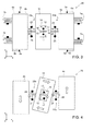
Figure 3 is a schematic top plan view of a micromechanical detection structure of a MEMS sensor device, according to a first embodiment of the present solution; -
Figure 4 shows the detection structure ofFigure 3 , whose driving movements have been highlighted; -
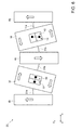
Figure 5 is a schematic top plan view of a micromechanical detection structure of a MEMS sensor device, according to a second embodiment of the present solution; -
Figure 6 shows the detection structure ofFigure 5 , whose driving movements have been highlighted; and -
Figure 7 is an overall block diagram of a MEMS sensor device. - As will be clarified hereinafter, the present solution stems from the realization, by the present Applicant, that the problems highlighted previously are in general due to a non-zero resultant of the forces and of the torques exerted by inertial effect on the substrate (and thus on the corresponding package) by the moving masses (driving masses and driven masses) at the corresponding anchorages, as a result of the driving movement.
- In particular, referring to
Figure 2 , in the detection structure 1 of a known type a torque is generated on thesubstrate 2 at thecoupling unit 14, due to rotation of the drivenmass 10 about the vertical axis z. - The present Applicant has realized that the aforesaid torque, transmitted to the
substrate 2 and to the package, causes, for example, undesirable couplings with other detection structures during electrical-testing operations, or in general undesirable disturbance effects. - A particular aspect of the present solution thus envisages, as will be described in detail, first with reference to
Figure 3 , providing a detection structure, designated by 20, in which the arrangement and configuration of the driving/driven masses and of the corresponding elastic elements for coupling and anchorage to thesubstrate 2, as well as the direction of the corresponding driving movements, are such as to originate a substantially and ideally zero resultant of the forces and of the torques exerted on thesubstrate 2 at the corresponding anchorages. - In other words, the inertial effects of the various mobile masses on the
substrate 2, in terms of forces and torques, are such as to compensate one another. - In detail, in a first embodiment, the
detection structure 20 is substantially equivalent to the detection structure 1 ofFigure 1 (elements that are similar are thus not described again herein and are designated by the same reference numbers), with the difference that it includes afirst coupling element 22a and asecond coupling element 22b, which elastically couple the drivenmass 10 to the first drivingmass 4a and to the second drivingmass 4b, respectively. - These
coupling elements mass 10; the resultant of the torques is thus substantially zero as a result of the driving movement. Thesecoupling elements mass 10, with respect to the traditional solution, described with reference toFigure 2 . - Each
coupling element rigid connection element 24 having a first end connected to the drivenmass 10 and a second end connected to the respectivedriving mass - The
rigid connection element 24 has a longitudinal extension, in the example along the first horizontal axis x, at rest. The aforesaidrigid connection element 24, which may ideally be considered as having infinite stiffness to bending, has, in an intermediate portion thereof between the drivenmass 10 and the respectivedriving mass masses substrate 2 of thedetection structure 20 at the aforesaid point of constraint, in the example by a pair ofrespective anchorages 25 to which the aforesaid intermediate portion is connected via respectiveelastic hinge elements 26. - The
rigid connection element 24 is thus ideally hinged at the centre to thesubstrate 2, and, at its ends, to the drivenmass 10 and to the respectivedriving mass - During operation, as shown schematically in
Figure 4 , therigid connection element 24 is free to rotate in the horizontal plane xy about the central point of constraint, but not to translate. Consequently, the driving movement of thedriving masses Figure 1 ). - In particular, as highlighted in the aforesaid
Figure 4 , thecoupling elements substrate 2, at the respective central constraint, a total torque (in a counterclockwise direction, in the example) equal and opposite to the torque (in a clockwise direction, in the example) exerted on thesame substrate 2 by thecoupling unit 14 of the drivenmass 10 at thecentral anchorage elements 17, due to rotation of the same drivenmass 10 about the vertical axis z. - Furthermore, in this embodiment, the resultant of the forces exerted on the
anchorages masses individual driving masses - Thus, advantageously, both the resultant of the forces and the resultant of the torques that act on the
substrate 2 are substantially zero. - In a way that will be evident from what has been discussed, the mechanical characteristics (for example, in terms of the inertial masses and of the stiffnesses of the elastic elements) of the driven
mass 10, of the drivingmasses substrate 2 are designed so as to ensure substantial equivalence, and thus mutual compensation, of the forces and torques generated in opposite directions, and substantial cancelling-out of the resultant of forces and torques acting on thesubstrate 2. - In a possible embodiment, each of the elastic hinge elements previously defined may comprise a respective pair of springs, which have longitudinal extension (for example, along the second horizontal axis y) and are set as prolongation of one another starting from the respective hinge point.
- With reference to
Figure 5 , a description of a second embodiment of the present solution is now presented, envisaging a different arrangement of the driving/driven masses and of the corresponding elastic elements for coupling and anchorage to thesubstrate 2, such as to originate once again a substantially zero resultant of the forces and torques exerted on thesame substrate 2 at the corresponding anchorages. - In particular, in this second embodiment, the detection structure, once again designated by 20, comprises a third driving
mass 4c, in the example substantially rectangular, having extension in the horizontal plane xy, and connected torespective anchorages 5c, fixed with respect to thesubstrate 2, by respectiveelastic anchorage elements 6c. The third drivingmass 4c is suspended above thesubstrate 2, parallel to thesame substrate 2 in the resting condition. - The third driving
mass 4c is arranged between the first andsecond driving masses mass 4c in this case represents the centroid and centre of symmetry of thedetection structure 20. - A respective set of driving
electrodes 7c is associated to the third drivingmass 4c, comprising a respective plurality ofmobile electrodes 8c, fixed with respect to the same third drivingmass 4c, as well as a respective plurality of fixedelectrodes 9c fixed with respect to thesubstrate 2 and comb-fingered with themobile electrodes 8c. - Appropriate electrical biasing signals from the electronic circuit (not illustrated) for driving the MEMS gyroscope, determine, by mutual and alternating electrostatic attraction of the electrodes, a respective driving movement of the third driving
mass 4c in a linear driving direction, in the example along the second horizontal axis y. - In particular, in this embodiment, as represented by the arrows in the next
Figure 6 , the first andsecond driving masses mass 4c is driven in the opposite sense of the same driving direction. - The
detection structure 20 in this case comprises: a pair of driven masses (suspended above thesubstrate 2, parallel thereto in the resting condition), and in particular: a first driven mass, designated once again by 10, arranged between the first andthird driving masses same driving masses elastic connection elements mass 30, arranged between the second andthird driving masses same driving masses elastic connection elements - Each driven
mass empty space respective coupling unit mass substrate 2. - Each
coupling unit rigid element empty space mass central anchorage elements elastic connection elements - In particular, in the example illustrated in
Figure 5 , theelastic connection elements 16 associated to the first drivenmass 10 have a linear extension along the second horizontal axis y, whereas theelastic connection elements 36 associated to the second drivenmass 30 have a linear extension along the first horizontal axis x (given that they are further configured so as to enable rotations of the same drivenmasses Figure 5 , therigid element 15 coupled to the first drivenmass 10 has a linear extension along the first horizontal axis x, whereas therigid element 35 coupled to the second drivenmass 30 has a linear extension along the second horizontal axis y. - During operation, as shown in
Figure 6 , in response to the driving movement, the first and second drivenmasses mass 10 in the counterclockwise direction and the second drivenmass 30 in the clockwise direction) in the plane of the sensor xy, with respect to thesubstrate 2 and about the vertical axis z. - Consequently, on the substrate 2 a substantially zero resultant torque is generated due to rotation of the driven
masses respective coupling units central anchorage elements - Once again, in fact, the mechanical characteristics (for example, in terms of inertial masses and stiffnesses) of the driven
masses respective coupling units substrate 2. - Also in this case, the resultant of the forces exerted on the
anchorages masses individual driving masses second driving masses mass 4c) are substantially compensated, once again thanks to the appropriate sizing of the mechanical characteristics of the drivingmasses - In this case, the detection movements are performed by the first and second driven
masses - The advantages of the solution proposed are clear from the foregoing description.
- In any case, it is emphasised once again that the present solution enables provision of micromechanical detection structures, in particular for MEMS sensor devices, for example MEMS gyroscopes, with a substantially zero resultant of the forces and of the torques acting on the substrate at the anchorages of the moving masses.
- In this way, it is possible to prevent transmission of undesirable stresses from the micromechanical detection structure to the substrate and the package of the sensor device, thus solving the problems highlighted previously, amongst which: undesirable couplings between detection structures during electrical testing thereof; vibrations induced in the corresponding package following upon the driving movement; oscillations and instability of the zero level; and sensitivity to undesirable external stresses and vibrations that lead to rotational accelerations about the vertical axis z.
- Even though both of the embodiments described previously have the same advantageous characteristics highlighted above, the first embodiment (
Figure 3 ) may, however, be more advantageous than the second embodiment (Figure 5 ), at least in some circumstances, for example owing to the presence of a smaller number of moving masses, a better area occupation, a smaller number of elastic coupling elements, and a greater resulting simplicity of construction and greater insensitivity to manufacturing process spread. - In any case, as mentioned previously, it is advantageous to use the
detection structure 20 in a MEMS sensor device. - In this regard,
Figure 7 shows schematically asensor device 40, for example a MEMS gyroscope, comprising thedetection structure 20, designed to generate at least one electrical detection quantity as a function at least one quantity of interest (for example, an angular velocity, in the case of a gyroscope); and an electronic circuit 42 (a so-called ASIC - Application-Specific Integrated Circuit), electrically coupled to thedetection structure 20 and designed to supply driving and biasing electrical quantities to thedetection structure 20 and further designed to process the electrical quantities detected, for example by amplification and filtering operations. - In particular, the
detection structure 20 and theelectronic circuit 42 may be made in respective dies of semiconductor material, which are housed in asame package 44, for example in a configuration where they are arranged side-by-side or vertically stacked on top of one another. - Finally, it is clear that modifications and variations may be made to what has been described and illustrated herein, without thereby departing from the scope of the present solution, as defined in the annexed claims.
- In this regard, it is emphasised once again that different embodiments may be envisaged, in addition to what has been illustrated previously by way of example, in which, in any case, the configuration and arrangement of the moving masses and of the corresponding elastic elements for coupling and anchorage to the substrate is such as to lead, following upon the appropriate driving movement, to a resultant force and a resultant twisting moment on the substrate that are substantially zero.
- In particular, different kinematic arrangements of the moving masses, and different configurations of the corresponding elements for anchorage to the substrate, may be envisaged.
- Furthermore, it is emphasised that the solution described may find advantageous application in bi-axial or tri-axial micromechanical detection structures, in MEMS gyroscopes, or also in different and further MEMS devices of an inertial type, in which it is desired to cancel out the resultant of the forces and torques acting on the substrate, or in any case to reduce them markedly, for example by at least a factor of ten.
Claims (16)
- A micromechanical detection structure (20), comprising:a substrate (2) including semiconductor material;a driving-mass arrangement (4a-4c), coupled to a set of driving electrodes (7a-7c) and designed to be driven in a driving movement following upon electrical biasing of said set of driving electrodes;a first anchorage unit (6a-6c), coupled to said driving-mass arrangement and configured to elastically couple said driving-mass arrangement to said substrate (2) at first anchorages (5a-5c);a driven-mass arrangement (10, 30), elastically coupled to said driving-mass arrangement (4a-4c) by a coupling unit (22a-22b; 11a-11b, 31a-31b), and designed to be driven in motion by said driving movement; anda second anchorage unit (14, 34), coupled to said driven-mass arrangement and configured to elastically couple said driven-mass arrangement to said substrate (2) at second anchorages (17, 37),characterized in that said driving-mass arrangement (4a-4c) and driven-mass arrangement (10, 30), said first anchorage unit (6a-6c) and second anchorage unit (14, 34), and said coupling unit (22a-22b; 11a-11b, 31a-31b), and said driving movement are jointly configured for cancelling out the resultant of the forces and torques acting on said substrate (2) at said first (5a-5c) and second (17, 37) anchorages.
- The structure according to claim 1, wherein, following upon said driving movement, first forces and torques acting on said substrate (2) at said first (5a-5c) and second (17, 37) anchorages in a first direction or sense are designed to compensate second forces and torques acting on said substrate (2) at said first (5a-5c) and second (17, 37) anchorages in a second direction or sense, opposite to the first direction or sense.
- The structure according to claim 1 or 2, having a planar extension in a horizontal plane (xy) defined by a first horizontal axis (x) and by a second horizontal axis (y); wherein said driving-mass arrangement comprises a first driving mass (4a) and a second driving mass (4b), designed to be driven in opposite directions along said second horizontal axis (y), and said driven-mass arrangement comprises a first driven mass (10), arranged between said first driving mass (4a) and said second driving mass (4b) along said first horizontal axis (x), and driven in a movement of rotation in said horizontal plane (xy) by said driving movement; and wherein said coupling unit (22a-22b) comprises a first coupling element (22a), which elastically couples said first driven mass (10) to the first driving mass (4a), and a second coupling element (22b), which elastically couples said first driven mass (10) to the second driving mass (4b), said first coupling element (22a) and said second coupling element (22b) being constrained to said substrate (2) and being configured to exert on said substrate (2) a torque equal and opposite to a respective torque exerted on said substrate (2) by said second anchorage unit (14) following upon rotation of said driven mass (10).
- The structure according to claim 3, wherein said first coupling element (22a) and said second coupling element (22b) are each configured so as to define a rigid connection element (24) having a first end connected with a hinged coupling to the driven mass (10) and a second end connected with a hinged coupling to the respective first driving mass (4a) or second driving mass (4b).
- The structure according to claim 4, wherein said rigid connection element (24) has, at an intermediate portion thereof between the driven mass (10) and the respective first driving mass (4a) or second driving mass (4b), a point of constraint to said substrate (2), said intermediate portion being hinged to the substrate (2) at said point of constraint.
- The structure according to claim 5, wherein said first coupling element (22a) and said second coupling element (22b) are each configured so as to operate as a rocker arm, or lever with central fulcrum, at said point of constraint.
- The structure according to claim 1 or 2, having planar extension in a horizontal plane (xy) defined by a first horizontal axis (x) and by a second horizontal axis (y); wherein said driving-mass arrangement comprises a first driving mass (4a) and a second driving mass (4b), designed to be driven in a driving movement in a same direction along said second horizontal axis (y), and moreover a third driving mass (4c), arranged between said first driving mass (4a) and said second driving mass (4b) along said first horizontal axis (x) and designed to be driven in an opposite direction along said second horizontal axis; and wherein said driven-mass arrangement comprises a first driven mass (10), arranged between said first driving mass (4a) and said third driving mass (4c) along said first horizontal axis (x), and driven in a first movement of rotation in said horizontal plane (xy) by said driving movement, and a second driven mass (30), arranged between said second driving mass (4b) and said third driving mass (4c) along said first horizontal axis (x), and driven in a second movement of rotation in said horizontal plane (xy) by said driving movement, said second movement of rotation having a direction opposite to said first movement of rotation.
- The structure according to claim 7, wherein said second anchorage unit (14, 34) comprises at least one first central anchorage (17), fixed with respect to said substrate (2), to which said first driven mass (10) is elastically connected, and at least one second central anchorage (37), fixed with respect to said substrate (2), to which said second driven mass (30) is elastically connected; wherein the first and second movements of rotation of said first driven mass (10) and said second driven mass (30) are designed to exert on said substrate (2) equal and opposite torques at said first central anchorage (17) and said second central anchorage (37).
- The structure according to claim 7 or 8, wherein said first driven mass (10) and said second driven mass (30) each have, at the centre, a respective window (12, 32), arranged inside which are said first anchorage unit (14) and said second anchorage unit (34), respectively.
- The structure according to any one of the preceding claims, wherein said driving-mass arrangement (4a-4c) and said driving movement are configured so that the resultant force on said substrate (2) at said first anchorages (5a-5b) is substantially zero.
- A MEMS sensor device (40), comprising the micromechanical detection structure (20) according to any one of the preceding claims.
- The device according to claim 11, further comprising an electronic circuit (42), electrically coupled to the micromechanical detection structure (20) and designed to supply electrical driving and biasing quantities to the micromechanical detection structure (20) and further designed to process at least one electrical quantity detected by said micromechanical detection structure (20).
- The device according to claim 12, wherein said micromechanical detection structure (20) and said electronic circuit (42) are integrated in respective dies, which include semiconductor material and are housed in a same package (44).
- The device according to any one of claims 11-13, defining a biaxial or triaxial MEMS gyroscope.
- A method for manufacturing a micromechanical detection structure (20), comprising the steps of:providing a substrate (2) including semiconductor material;forming a driving-mass arrangement (4a-4c), including coupling a set of driving electrodes (7a-7c) to said driving mass so that the driving mass is driven in a driving movement following upon biasing of said set of driving electrodes;elastically coupling said driving-mass arrangement to said substrate (2) at first anchorages (5a-5c);elastically coupling a driven-mass arrangement (10, 30) to said driving-mass arrangement (4a-4c) by a coupling unit (22a-22b; 11a-11b, 31a-31b), so that it is driven in movement by said driving movement; andelastically coupling said driven-mass arrangement to said substrate (2) at second anchorages (17, 37);characterized in that said steps of forming a driving-mass arrangement (4a-4c) and elastic coupling are jointly configured to cancel out the resultant of the forces and of the torques acting on said substrate (2) at said first anchorages (5a-5c) and said second anchorages (17, 37).
- The method according to claim 15, wherein, following upon said driving movement, the resultant of the forces and of the torques acting on said substrate (2) at said first anchorages (5a-5c) and said second anchorages (17, 37) is substantially zero.
Applications Claiming Priority (1)
| Application Number | Priority Date | Filing Date | Title |
|---|---|---|---|
| ITUA2016A001498A ITUA20161498A1 (en) | 2016-03-09 | 2016-03-09 | MICROMECHANICAL DETECTION STRUCTURE OF A MEMS SENSOR DEVICE, IN PARTICULAR OF A MEMS GYRO, WITH IMPROVED DRIVE CHARACTERISTICS |
Publications (2)
| Publication Number | Publication Date |
|---|---|
| EP3217147A1 true EP3217147A1 (en) | 2017-09-13 |
| EP3217147B1 EP3217147B1 (en) | 2018-12-12 |
Family
ID=56026951
Family Applications (1)
| Application Number | Title | Priority Date | Filing Date |
|---|---|---|---|
| EP16194684.3A Active EP3217147B1 (en) | 2016-03-09 | 2016-10-19 | Micromechanical detection structure for a mems sensor device, in particular a mems gyroscope, with improved driving features |
Country Status (4)
| Country | Link |
|---|---|
| US (2) | US10458794B2 (en) |
| EP (1) | EP3217147B1 (en) |
| CN (2) | CN107179074B (en) |
| IT (1) | ITUA20161498A1 (en) |
Families Citing this family (13)
| Publication number | Priority date | Publication date | Assignee | Title |
|---|---|---|---|---|
| US10330471B2 (en) * | 2014-11-27 | 2019-06-25 | Goertek, Inc. | Triaxial micro-electromechanical gyroscope |
| ITUA20162172A1 (en) * | 2016-03-31 | 2017-10-01 | St Microelectronics Srl | ACCELEROMETRIC SENSOR MADE IN MEMS TECHNOLOGY WITH HIGH ACCURACY AND REDUCED SENSITIVITY TOWARDS TEMPERATURE AND AGING |
| DE102017219933A1 (en) * | 2017-11-09 | 2019-05-09 | Robert Bosch Gmbh | Yaw rate sensor with a main extension plane having a substrate, manufacturing method for a rotation rate sensor |
| JP7188311B2 (en) | 2019-07-31 | 2022-12-13 | セイコーエプソン株式会社 | Gyro sensors, electronic devices, and mobile objects |
| IT201900017546A1 (en) | 2019-09-30 | 2021-03-30 | St Microelectronics Srl | WATER RESISTANT MEMS BUTTON DEVICE, INPUT DEVICE INCLUDING MEMS BUTTON DEVICE AND ELECTRONIC DEVICE |
| CN110926445B (en) * | 2019-12-06 | 2022-03-08 | 深迪半导体(绍兴)有限公司 | Three-axis MEMS gyroscope |
| CN113970324B (en) * | 2020-07-23 | 2023-09-05 | 昇佳电子股份有限公司 | The structure of the gyroscope |
| CN114459453B (en) * | 2021-12-24 | 2025-06-17 | 瑞声开泰科技(武汉)有限公司 | Micromechanical gyroscopes and electronic products |
| CN114858152B (en) * | 2022-03-30 | 2025-06-17 | 瑞声开泰科技(武汉)有限公司 | A MEMS single-axis gyroscope |
| CN115493577B (en) * | 2022-08-16 | 2025-01-17 | 瑞声开泰科技(武汉)有限公司 | Triaxial gyroscope |
| TWI872680B (en) * | 2022-09-02 | 2025-02-11 | 昇佳電子股份有限公司 | Three-axis gyroscope |
| CN115979235B (en) * | 2023-02-14 | 2026-03-20 | 瑞声开泰科技(武汉)有限公司 | A micromechanical gyroscope and electronic product |
| CN116045939A (en) * | 2023-02-15 | 2023-05-02 | 瑞声开泰科技(武汉)有限公司 | A kind of micromechanical gyroscope and electronic product |
Citations (4)
| Publication number | Priority date | Publication date | Assignee | Title |
|---|---|---|---|---|
| US20100024547A1 (en) * | 2008-07-29 | 2010-02-04 | Fujitsu Limited | Angular speed sensor and electronic apparatus |
| US20110041603A1 (en) * | 2009-08-18 | 2011-02-24 | Odd-Axel Pruetz | Yaw rate sensor and method for operating a yaw rate sensor |
| US20130174661A1 (en) * | 2012-01-05 | 2013-07-11 | Burkhard Kuhlmann | Rotation rate sensor and method for operating a rotation rate sensor |
| EP2884229A1 (en) * | 2013-09-30 | 2015-06-17 | InvenSense, Inc. | Micromachined gyroscope including a guided mass system |
Family Cites Families (26)
| Publication number | Priority date | Publication date | Assignee | Title |
|---|---|---|---|---|
| US6189381B1 (en) * | 1999-04-26 | 2001-02-20 | Sitek, Inc. | Angular rate sensor made from a structural wafer of single crystal silicon |
| US7222533B2 (en) * | 2005-06-06 | 2007-05-29 | Bei Technologies, Inc. | Torsional rate sensor with momentum balance and mode decoupling |
| EP1832841B1 (en) * | 2006-03-10 | 2015-12-30 | STMicroelectronics Srl | Microelectromechanical integrated sensor structure with rotary driving motion |
| US8042396B2 (en) * | 2007-09-11 | 2011-10-25 | Stmicroelectronics S.R.L. | Microelectromechanical sensor with improved mechanical decoupling of sensing and driving modes |
| DE102008041757B4 (en) * | 2008-09-02 | 2019-01-03 | Robert Bosch Gmbh | Manufacturing method for a rotation sensor device and rotation sensor device |
| IT1391972B1 (en) * | 2008-11-26 | 2012-02-02 | St Microelectronics Rousset | MICROELETTROMECHANICAL GYROSCOPE WITH ROTARY DRIVE MOVEMENT AND IMPROVED ELECTRICAL CHARACTERISTICS |
| IT1392741B1 (en) * | 2008-12-23 | 2012-03-16 | St Microelectronics Rousset | MICROELETTROMECHANICAL GYROSCOPE WITH IMPROVED REJECTION OF ACCELERATION DISORDERS |
| US8183944B2 (en) * | 2009-04-03 | 2012-05-22 | Invensense, Inc. | Method and system for using a MEMS structure as a timing source |
| DE102009026507A1 (en) * | 2009-05-27 | 2010-12-02 | Robert Bosch Gmbh | Micromechanical component and production method for a micromechanical component |
| DE202009007836U1 (en) * | 2009-06-03 | 2009-08-20 | Sensordynamics Ag | MEMS sensor |
| ITTO20090597A1 (en) * | 2009-07-31 | 2011-02-01 | St Microelectronics Srl | Z AXIS MICROELETTROMECHANICAL DETECTION STRUCTURE WITH REDUCED THERMAL DERIVATIONS |
| FR2962532B1 (en) * | 2010-07-07 | 2013-11-29 | Commissariat Energie Atomique | INERTIAL SENSOR OF OSCILLATING DISC ROTATIONS |
| DE102012200929B4 (en) * | 2012-01-23 | 2020-10-01 | Robert Bosch Gmbh | Micromechanical structure and method for manufacturing a micromechanical structure |
| JP6143430B2 (en) * | 2012-05-08 | 2017-06-07 | 三菱プレシジョン株式会社 | Vibration gyro with bias correction function |
| WO2014120206A1 (en) * | 2013-01-31 | 2014-08-07 | Hewlett-Packard Development Company, L.P. | Sensor having particle barrier |
| US9476711B2 (en) * | 2013-06-24 | 2016-10-25 | Freescale Semiconductor, Inc. | Angular rate sensor with quadrature error compensation |
| DE102013216898B4 (en) * | 2013-08-26 | 2023-02-09 | Robert Bosch Gmbh | Micromechanical component and method for producing a micromechanical component |
| US9404747B2 (en) * | 2013-10-30 | 2016-08-02 | Stmicroelectroncs S.R.L. | Microelectromechanical gyroscope with compensation of quadrature error drift |
| FI20155095A7 (en) * | 2015-02-11 | 2016-08-12 | Murata Manufacturing Co | Micromechanical sensor of angular velocity |
| US20180188028A1 (en) * | 2015-10-26 | 2018-07-05 | Panasonic Corporation | Single-gap shock-stop structure and methods of manufacture for micro-machined mems devices |
| ITUA20162160A1 (en) * | 2016-03-31 | 2017-10-01 | St Microelectronics Srl | MICROMECHANICAL STRUCTURE FOR DETECTION OF A MEMS MULTI-FACTORY GYROSCOPE, HAVING REDUCED DERIVED FROM RELATED ELECTRICAL CHARACTERISTICS |
| DE102016208925B4 (en) * | 2016-05-24 | 2024-11-21 | Robert Bosch Gmbh | Micromechanical sensor and method for producing a micromechanical sensor |
| US20180031603A1 (en) * | 2016-07-27 | 2018-02-01 | Lumedyne Technologies Incorporated | Systems and methods for detecting inertial parameters using a vibratory accelerometer with multiple degrees of freedom |
| IT201700043012A1 (en) * | 2017-04-19 | 2018-10-19 | St Microelectronics Srl | MEMS GYROSCOPE WITH IMPROVED REJECTION OF A SQUARE ERROR |
| IT201700099412A1 (en) * | 2017-09-05 | 2019-03-05 | St Microelectronics Srl | MEMS GYROSCOPE WITH MISMATCH ADJUSTMENT BETWEEN PILOT FREQUENCY AND DETECTION FREQUENCY |
| JP6922961B2 (en) * | 2018-10-18 | 2021-08-18 | 株式会社村田製作所 | Micro electromechanical device for rotational motion detection |
-
2016
- 2016-03-09 IT ITUA2016A001498A patent/ITUA20161498A1/en unknown
- 2016-09-30 CN CN201610877204.2A patent/CN107179074B/en active Active
- 2016-09-30 CN CN201621103727.3U patent/CN206440281U/en active Active
- 2016-10-19 EP EP16194684.3A patent/EP3217147B1/en active Active
-
2017
- 2017-03-09 US US15/454,907 patent/US10458794B2/en active Active
-
2019
- 2019-10-25 US US16/664,041 patent/US11015933B2/en active Active
Patent Citations (4)
| Publication number | Priority date | Publication date | Assignee | Title |
|---|---|---|---|---|
| US20100024547A1 (en) * | 2008-07-29 | 2010-02-04 | Fujitsu Limited | Angular speed sensor and electronic apparatus |
| US20110041603A1 (en) * | 2009-08-18 | 2011-02-24 | Odd-Axel Pruetz | Yaw rate sensor and method for operating a yaw rate sensor |
| US20130174661A1 (en) * | 2012-01-05 | 2013-07-11 | Burkhard Kuhlmann | Rotation rate sensor and method for operating a rotation rate sensor |
| EP2884229A1 (en) * | 2013-09-30 | 2015-06-17 | InvenSense, Inc. | Micromachined gyroscope including a guided mass system |
Also Published As
| Publication number | Publication date |
|---|---|
| US20170261322A1 (en) | 2017-09-14 |
| US10458794B2 (en) | 2019-10-29 |
| CN206440281U (en) | 2017-08-25 |
| US11015933B2 (en) | 2021-05-25 |
| CN107179074B (en) | 2021-06-11 |
| EP3217147B1 (en) | 2018-12-12 |
| ITUA20161498A1 (en) | 2017-09-09 |
| US20200064134A1 (en) | 2020-02-27 |
| CN107179074A (en) | 2017-09-19 |
Similar Documents
| Publication | Publication Date | Title |
|---|---|---|
| EP3217147B1 (en) | Micromechanical detection structure for a mems sensor device, in particular a mems gyroscope, with improved driving features | |
| US11808574B2 (en) | Micromechanical detection structure of a MEMS multi-axis gyroscope, with reduced drifts of corresponding electrical parameters | |
| US12584940B2 (en) | MEMS tri-axial accelerometer with one or more decoupling elements | |
| EP2462408B1 (en) | Micromachined inertial sensor devices | |
| EP3428576B1 (en) | Angular rate sensor with in-phase motion suppression structure | |
| US8739626B2 (en) | Micromachined inertial sensor devices | |
| US10655963B2 (en) | Anchoring structure for a sensor insensitive to anchor movement | |
| CN104094084B (en) | Microelectromechanical system (MEMS) mass with split z-axis sections | |
| CN103221778B (en) | There is single micromechanics one chip three-axis gyroscope driven | |
| EP2713169B1 (en) | Integrated resonant structure for the detection of acceleration and angular velocity, and related MEMS sensor device | |
| EP3607266B1 (en) | Out-of-plane sensing gyroscope robust to external acceleration and rotation | |
| US10551191B2 (en) | Deformation rejection mechanism for offset minimization of out-of-plane sensing MEMS device | |
| JP2021004875A (en) | Capacitance type micro mechanical accelerometer | |
| US7267005B1 (en) | SOI-MEMS gyroscope having three-fold symmetry | |
| EP3347674B1 (en) | An electrode for a microelectromechanical device | |
| CN111316062A (en) | Rotational speed sensor with substrate with main plane of extension, method for producing a rotational speed sensor | |
| EP4718026A2 (en) | Triaxial microelectromechanical gyroscope with improved performances | |
| WO2019209659A1 (en) | Deformation rejection mechanism for offset minimization of out-of-plane sensing mems device |
Legal Events
| Date | Code | Title | Description |
|---|---|---|---|
| PUAI | Public reference made under article 153(3) epc to a published international application that has entered the european phase |
Free format text: ORIGINAL CODE: 0009012 |
|
| STAA | Information on the status of an ep patent application or granted ep patent |
Free format text: STATUS: THE APPLICATION HAS BEEN PUBLISHED |
|
| AK | Designated contracting states |
Kind code of ref document: A1 Designated state(s): AL AT BE BG CH CY CZ DE DK EE ES FI FR GB GR HR HU IE IS IT LI LT LU LV MC MK MT NL NO PL PT RO RS SE SI SK SM TR |
|
| AX | Request for extension of the european patent |
Extension state: BA ME |
|
| STAA | Information on the status of an ep patent application or granted ep patent |
Free format text: STATUS: REQUEST FOR EXAMINATION WAS MADE |
|
| 17P | Request for examination filed |
Effective date: 20180312 |
|
| RBV | Designated contracting states (corrected) |
Designated state(s): AL AT BE BG CH CY CZ DE DK EE ES FI FR GB GR HR HU IE IS IT LI LT LU LV MC MK MT NL NO PL PT RO RS SE SI SK SM TR |
|
| GRAP | Despatch of communication of intention to grant a patent |
Free format text: ORIGINAL CODE: EPIDOSNIGR1 |
|
| STAA | Information on the status of an ep patent application or granted ep patent |
Free format text: STATUS: GRANT OF PATENT IS INTENDED |
|
| INTG | Intention to grant announced |
Effective date: 20180608 |
|
| GRAS | Grant fee paid |
Free format text: ORIGINAL CODE: EPIDOSNIGR3 |
|
| GRAA | (expected) grant |
Free format text: ORIGINAL CODE: 0009210 |
|
| STAA | Information on the status of an ep patent application or granted ep patent |
Free format text: STATUS: THE PATENT HAS BEEN GRANTED |
|
| AK | Designated contracting states |
Kind code of ref document: B1 Designated state(s): AL AT BE BG CH CY CZ DE DK EE ES FI FR GB GR HR HU IE IS IT LI LT LU LV MC MK MT NL NO PL PT RO RS SE SI SK SM TR |
|
| REG | Reference to a national code |
Ref country code: GB Ref legal event code: FG4D |
|
| REG | Reference to a national code |
Ref country code: CH Ref legal event code: EP |
|
| REG | Reference to a national code |
Ref country code: AT Ref legal event code: REF Ref document number: 1076615 Country of ref document: AT Kind code of ref document: T Effective date: 20181215 |
|
| REG | Reference to a national code |
Ref country code: DE Ref legal event code: R096 Ref document number: 602016008101 Country of ref document: DE |
|
| REG | Reference to a national code |
Ref country code: IE Ref legal event code: FG4D |
|
| REG | Reference to a national code |
Ref country code: NL Ref legal event code: MP Effective date: 20181212 |
|
| REG | Reference to a national code |
Ref country code: LT Ref legal event code: MG4D |
|
| PG25 | Lapsed in a contracting state [announced via postgrant information from national office to epo] |
Ref country code: BG Free format text: LAPSE BECAUSE OF FAILURE TO SUBMIT A TRANSLATION OF THE DESCRIPTION OR TO PAY THE FEE WITHIN THE PRESCRIBED TIME-LIMIT Effective date: 20190312 Ref country code: NO Free format text: LAPSE BECAUSE OF FAILURE TO SUBMIT A TRANSLATION OF THE DESCRIPTION OR TO PAY THE FEE WITHIN THE PRESCRIBED TIME-LIMIT Effective date: 20190312 Ref country code: FI Free format text: LAPSE BECAUSE OF FAILURE TO SUBMIT A TRANSLATION OF THE DESCRIPTION OR TO PAY THE FEE WITHIN THE PRESCRIBED TIME-LIMIT Effective date: 20181212 Ref country code: LT Free format text: LAPSE BECAUSE OF FAILURE TO SUBMIT A TRANSLATION OF THE DESCRIPTION OR TO PAY THE FEE WITHIN THE PRESCRIBED TIME-LIMIT Effective date: 20181212 Ref country code: LV Free format text: LAPSE BECAUSE OF FAILURE TO SUBMIT A TRANSLATION OF THE DESCRIPTION OR TO PAY THE FEE WITHIN THE PRESCRIBED TIME-LIMIT Effective date: 20181212 Ref country code: HR Free format text: LAPSE BECAUSE OF FAILURE TO SUBMIT A TRANSLATION OF THE DESCRIPTION OR TO PAY THE FEE WITHIN THE PRESCRIBED TIME-LIMIT Effective date: 20181212 Ref country code: ES Free format text: LAPSE BECAUSE OF FAILURE TO SUBMIT A TRANSLATION OF THE DESCRIPTION OR TO PAY THE FEE WITHIN THE PRESCRIBED TIME-LIMIT Effective date: 20181212 |
|
| REG | Reference to a national code |
Ref country code: AT Ref legal event code: MK05 Ref document number: 1076615 Country of ref document: AT Kind code of ref document: T Effective date: 20181212 |
|
| PG25 | Lapsed in a contracting state [announced via postgrant information from national office to epo] |
Ref country code: GR Free format text: LAPSE BECAUSE OF FAILURE TO SUBMIT A TRANSLATION OF THE DESCRIPTION OR TO PAY THE FEE WITHIN THE PRESCRIBED TIME-LIMIT Effective date: 20190313 Ref country code: RS Free format text: LAPSE BECAUSE OF FAILURE TO SUBMIT A TRANSLATION OF THE DESCRIPTION OR TO PAY THE FEE WITHIN THE PRESCRIBED TIME-LIMIT Effective date: 20181212 Ref country code: SE Free format text: LAPSE BECAUSE OF FAILURE TO SUBMIT A TRANSLATION OF THE DESCRIPTION OR TO PAY THE FEE WITHIN THE PRESCRIBED TIME-LIMIT Effective date: 20181212 Ref country code: AL Free format text: LAPSE BECAUSE OF FAILURE TO SUBMIT A TRANSLATION OF THE DESCRIPTION OR TO PAY THE FEE WITHIN THE PRESCRIBED TIME-LIMIT Effective date: 20181212 |
|
| PG25 | Lapsed in a contracting state [announced via postgrant information from national office to epo] |
Ref country code: NL Free format text: LAPSE BECAUSE OF FAILURE TO SUBMIT A TRANSLATION OF THE DESCRIPTION OR TO PAY THE FEE WITHIN THE PRESCRIBED TIME-LIMIT Effective date: 20181212 |
|
| PG25 | Lapsed in a contracting state [announced via postgrant information from national office to epo] |
Ref country code: IT Free format text: LAPSE BECAUSE OF FAILURE TO SUBMIT A TRANSLATION OF THE DESCRIPTION OR TO PAY THE FEE WITHIN THE PRESCRIBED TIME-LIMIT Effective date: 20181212 Ref country code: PT Free format text: LAPSE BECAUSE OF FAILURE TO SUBMIT A TRANSLATION OF THE DESCRIPTION OR TO PAY THE FEE WITHIN THE PRESCRIBED TIME-LIMIT Effective date: 20190412 Ref country code: CZ Free format text: LAPSE BECAUSE OF FAILURE TO SUBMIT A TRANSLATION OF THE DESCRIPTION OR TO PAY THE FEE WITHIN THE PRESCRIBED TIME-LIMIT Effective date: 20181212 Ref country code: PL Free format text: LAPSE BECAUSE OF FAILURE TO SUBMIT A TRANSLATION OF THE DESCRIPTION OR TO PAY THE FEE WITHIN THE PRESCRIBED TIME-LIMIT Effective date: 20181212 |
|
| PG25 | Lapsed in a contracting state [announced via postgrant information from national office to epo] |
Ref country code: IS Free format text: LAPSE BECAUSE OF FAILURE TO SUBMIT A TRANSLATION OF THE DESCRIPTION OR TO PAY THE FEE WITHIN THE PRESCRIBED TIME-LIMIT Effective date: 20190412 Ref country code: SK Free format text: LAPSE BECAUSE OF FAILURE TO SUBMIT A TRANSLATION OF THE DESCRIPTION OR TO PAY THE FEE WITHIN THE PRESCRIBED TIME-LIMIT Effective date: 20181212 Ref country code: RO Free format text: LAPSE BECAUSE OF FAILURE TO SUBMIT A TRANSLATION OF THE DESCRIPTION OR TO PAY THE FEE WITHIN THE PRESCRIBED TIME-LIMIT Effective date: 20181212 Ref country code: SM Free format text: LAPSE BECAUSE OF FAILURE TO SUBMIT A TRANSLATION OF THE DESCRIPTION OR TO PAY THE FEE WITHIN THE PRESCRIBED TIME-LIMIT Effective date: 20181212 Ref country code: EE Free format text: LAPSE BECAUSE OF FAILURE TO SUBMIT A TRANSLATION OF THE DESCRIPTION OR TO PAY THE FEE WITHIN THE PRESCRIBED TIME-LIMIT Effective date: 20181212 |
|
| REG | Reference to a national code |
Ref country code: DE Ref legal event code: R097 Ref document number: 602016008101 Country of ref document: DE |
|
| PLBE | No opposition filed within time limit |
Free format text: ORIGINAL CODE: 0009261 |
|
| STAA | Information on the status of an ep patent application or granted ep patent |
Free format text: STATUS: NO OPPOSITION FILED WITHIN TIME LIMIT |
|
| PG25 | Lapsed in a contracting state [announced via postgrant information from national office to epo] |
Ref country code: DK Free format text: LAPSE BECAUSE OF FAILURE TO SUBMIT A TRANSLATION OF THE DESCRIPTION OR TO PAY THE FEE WITHIN THE PRESCRIBED TIME-LIMIT Effective date: 20181212 Ref country code: AT Free format text: LAPSE BECAUSE OF FAILURE TO SUBMIT A TRANSLATION OF THE DESCRIPTION OR TO PAY THE FEE WITHIN THE PRESCRIBED TIME-LIMIT Effective date: 20181212 Ref country code: SI Free format text: LAPSE BECAUSE OF FAILURE TO SUBMIT A TRANSLATION OF THE DESCRIPTION OR TO PAY THE FEE WITHIN THE PRESCRIBED TIME-LIMIT Effective date: 20181212 |
|
| 26N | No opposition filed |
Effective date: 20190913 |
|
| PG25 | Lapsed in a contracting state [announced via postgrant information from national office to epo] |
Ref country code: TR Free format text: LAPSE BECAUSE OF FAILURE TO SUBMIT A TRANSLATION OF THE DESCRIPTION OR TO PAY THE FEE WITHIN THE PRESCRIBED TIME-LIMIT Effective date: 20181212 |
|
| PG25 | Lapsed in a contracting state [announced via postgrant information from national office to epo] |
Ref country code: MC Free format text: LAPSE BECAUSE OF FAILURE TO SUBMIT A TRANSLATION OF THE DESCRIPTION OR TO PAY THE FEE WITHIN THE PRESCRIBED TIME-LIMIT Effective date: 20181212 |
|
| REG | Reference to a national code |
Ref country code: CH Ref legal event code: PL |
|
| PG25 | Lapsed in a contracting state [announced via postgrant information from national office to epo] |
Ref country code: LI Free format text: LAPSE BECAUSE OF NON-PAYMENT OF DUE FEES Effective date: 20191031 Ref country code: CH Free format text: LAPSE BECAUSE OF NON-PAYMENT OF DUE FEES Effective date: 20191031 Ref country code: LU Free format text: LAPSE BECAUSE OF NON-PAYMENT OF DUE FEES Effective date: 20191019 |
|
| REG | Reference to a national code |
Ref country code: BE Ref legal event code: MM Effective date: 20191031 |
|
| PG25 | Lapsed in a contracting state [announced via postgrant information from national office to epo] |
Ref country code: BE Free format text: LAPSE BECAUSE OF NON-PAYMENT OF DUE FEES Effective date: 20191031 |
|
| PG25 | Lapsed in a contracting state [announced via postgrant information from national office to epo] |
Ref country code: FR Free format text: LAPSE BECAUSE OF NON-PAYMENT OF DUE FEES Effective date: 20191031 Ref country code: IE Free format text: LAPSE BECAUSE OF NON-PAYMENT OF DUE FEES Effective date: 20191019 |
|
| PG25 | Lapsed in a contracting state [announced via postgrant information from national office to epo] |
Ref country code: CY Free format text: LAPSE BECAUSE OF FAILURE TO SUBMIT A TRANSLATION OF THE DESCRIPTION OR TO PAY THE FEE WITHIN THE PRESCRIBED TIME-LIMIT Effective date: 20181212 |
|
| GBPC | Gb: european patent ceased through non-payment of renewal fee |
Effective date: 20201019 |
|
| PG25 | Lapsed in a contracting state [announced via postgrant information from national office to epo] |
Ref country code: MT Free format text: LAPSE BECAUSE OF FAILURE TO SUBMIT A TRANSLATION OF THE DESCRIPTION OR TO PAY THE FEE WITHIN THE PRESCRIBED TIME-LIMIT Effective date: 20181212 Ref country code: HU Free format text: LAPSE BECAUSE OF FAILURE TO SUBMIT A TRANSLATION OF THE DESCRIPTION OR TO PAY THE FEE WITHIN THE PRESCRIBED TIME-LIMIT; INVALID AB INITIO Effective date: 20161019 |
|
| PG25 | Lapsed in a contracting state [announced via postgrant information from national office to epo] |
Ref country code: GB Free format text: LAPSE BECAUSE OF NON-PAYMENT OF DUE FEES Effective date: 20201019 |
|
| PG25 | Lapsed in a contracting state [announced via postgrant information from national office to epo] |
Ref country code: MK Free format text: LAPSE BECAUSE OF FAILURE TO SUBMIT A TRANSLATION OF THE DESCRIPTION OR TO PAY THE FEE WITHIN THE PRESCRIBED TIME-LIMIT Effective date: 20181212 |
|
| PGFP | Annual fee paid to national office [announced via postgrant information from national office to epo] |
Ref country code: DE Payment date: 20250923 Year of fee payment: 10 |