EP3217012A1 - Discharge acoustic filter, manufacturing process of discharge acoustic filter and hermetic compressor - Google Patents
Discharge acoustic filter, manufacturing process of discharge acoustic filter and hermetic compressor Download PDFInfo
- Publication number
- EP3217012A1 EP3217012A1 EP17160173.5A EP17160173A EP3217012A1 EP 3217012 A1 EP3217012 A1 EP 3217012A1 EP 17160173 A EP17160173 A EP 17160173A EP 3217012 A1 EP3217012 A1 EP 3217012A1
- Authority
- EP
- European Patent Office
- Prior art keywords
- discharge chamber
- discharge
- acoustic filter
- manufacture
- duct
- Prior art date
- Legal status (The legal status is an assumption and is not a legal conclusion. Google has not performed a legal analysis and makes no representation as to the accuracy of the status listed.)
- Withdrawn
Links
- 238000004519 manufacturing process Methods 0.000 title claims description 37
- 239000000463 material Substances 0.000 abstract description 8
- 238000011089 mechanical engineering Methods 0.000 abstract description 2
- 238000005265 energy consumption Methods 0.000 abstract 1
- 239000012530 fluid Substances 0.000 description 9
- 238000003466 welding Methods 0.000 description 4
- 229910000831 Steel Inorganic materials 0.000 description 3
- 239000010959 steel Substances 0.000 description 3
- 238000013475 authorization Methods 0.000 description 2
- 230000005540 biological transmission Effects 0.000 description 2
- 238000005219 brazing Methods 0.000 description 2
- 238000001816 cooling Methods 0.000 description 2
- 230000010354 integration Effects 0.000 description 2
- 239000002184 metal Substances 0.000 description 2
- 229910052751 metal Inorganic materials 0.000 description 2
- 238000000034 method Methods 0.000 description 2
- 229910001018 Cast iron Inorganic materials 0.000 description 1
- RYGMFSIKBFXOCR-UHFFFAOYSA-N Copper Chemical compound [Cu] RYGMFSIKBFXOCR-UHFFFAOYSA-N 0.000 description 1
- 241001644893 Entandrophragma utile Species 0.000 description 1
- 239000000853 adhesive Substances 0.000 description 1
- 238000004026 adhesive bonding Methods 0.000 description 1
- 230000001070 adhesive effect Effects 0.000 description 1
- 229910052802 copper Inorganic materials 0.000 description 1
- 239000010949 copper Substances 0.000 description 1
- 230000008878 coupling Effects 0.000 description 1
- 238000010168 coupling process Methods 0.000 description 1
- 238000005859 coupling reaction Methods 0.000 description 1
- 230000000694 effects Effects 0.000 description 1
- 230000006698 induction Effects 0.000 description 1
- 239000007769 metal material Substances 0.000 description 1
- 238000005192 partition Methods 0.000 description 1
- 230000001737 promoting effect Effects 0.000 description 1
Images


Classifications
-
- F—MECHANICAL ENGINEERING; LIGHTING; HEATING; WEAPONS; BLASTING
- F04—POSITIVE - DISPLACEMENT MACHINES FOR LIQUIDS; PUMPS FOR LIQUIDS OR ELASTIC FLUIDS
- F04B—POSITIVE-DISPLACEMENT MACHINES FOR LIQUIDS; PUMPS
- F04B39/00—Component parts, details, or accessories, of pumps or pumping systems specially adapted for elastic fluids, not otherwise provided for in, or of interest apart from, groups F04B25/00 - F04B37/00
- F04B39/0027—Pulsation and noise damping means
- F04B39/0055—Pulsation and noise damping means with a special shape of fluid passage, e.g. bends, throttles, diameter changes, pipes
-
- F—MECHANICAL ENGINEERING; LIGHTING; HEATING; WEAPONS; BLASTING
- F04—POSITIVE - DISPLACEMENT MACHINES FOR LIQUIDS; PUMPS FOR LIQUIDS OR ELASTIC FLUIDS
- F04B—POSITIVE-DISPLACEMENT MACHINES FOR LIQUIDS; PUMPS
- F04B39/00—Component parts, details, or accessories, of pumps or pumping systems specially adapted for elastic fluids, not otherwise provided for in, or of interest apart from, groups F04B25/00 - F04B37/00
- F04B39/0027—Pulsation and noise damping means
- F04B39/0055—Pulsation and noise damping means with a special shape of fluid passage, e.g. bends, throttles, diameter changes, pipes
- F04B39/0061—Pulsation and noise damping means with a special shape of fluid passage, e.g. bends, throttles, diameter changes, pipes using muffler volumes
-
- F—MECHANICAL ENGINEERING; LIGHTING; HEATING; WEAPONS; BLASTING
- F04—POSITIVE - DISPLACEMENT MACHINES FOR LIQUIDS; PUMPS FOR LIQUIDS OR ELASTIC FLUIDS
- F04B—POSITIVE-DISPLACEMENT MACHINES FOR LIQUIDS; PUMPS
- F04B39/00—Component parts, details, or accessories, of pumps or pumping systems specially adapted for elastic fluids, not otherwise provided for in, or of interest apart from, groups F04B25/00 - F04B37/00
- F04B39/0027—Pulsation and noise damping means
- F04B39/0055—Pulsation and noise damping means with a special shape of fluid passage, e.g. bends, throttles, diameter changes, pipes
- F04B39/0072—Pulsation and noise damping means with a special shape of fluid passage, e.g. bends, throttles, diameter changes, pipes characterised by assembly or mounting
-
- F—MECHANICAL ENGINEERING; LIGHTING; HEATING; WEAPONS; BLASTING
- F04—POSITIVE - DISPLACEMENT MACHINES FOR LIQUIDS; PUMPS FOR LIQUIDS OR ELASTIC FLUIDS
- F04B—POSITIVE-DISPLACEMENT MACHINES FOR LIQUIDS; PUMPS
- F04B39/00—Component parts, details, or accessories, of pumps or pumping systems specially adapted for elastic fluids, not otherwise provided for in, or of interest apart from, groups F04B25/00 - F04B37/00
- F04B39/12—Casings; Cylinders; Cylinder heads; Fluid connections
-
- F—MECHANICAL ENGINEERING; LIGHTING; HEATING; WEAPONS; BLASTING
- F04—POSITIVE - DISPLACEMENT MACHINES FOR LIQUIDS; PUMPS FOR LIQUIDS OR ELASTIC FLUIDS
- F04B—POSITIVE-DISPLACEMENT MACHINES FOR LIQUIDS; PUMPS
- F04B39/00—Component parts, details, or accessories, of pumps or pumping systems specially adapted for elastic fluids, not otherwise provided for in, or of interest apart from, groups F04B25/00 - F04B37/00
- F04B39/12—Casings; Cylinders; Cylinder heads; Fluid connections
- F04B39/125—Cylinder heads
Definitions
- the present invention lies in the field of mechanical engineering. More specifically, the present invention describes a discharge acoustic filter made of polymeric material that has the interconnections of expansion chambers through internal ducts.
- Discharge acoustic filters are already widely used coupled to compressors for reducing pulses generated by the compressors.
- Discharge acoustic filters are generally made of steel, which can be stamped and machined, which have a wide variety of parts, and can be made integrated to the cast iron block.
- discharge acoustic filters made of steel are large, heavy and present a large surface area that increases the heat exchange between the compressor and the hermetic volume.
- Discharge acoustic filters made of steel have a greater complexity of assembly, because the tubes that make the connections between the expansion chambers, the cylinder cover and the remaining of the system are made of copper and are assembled by brazing and must be conformed in specific formats.
- the discharge acoustic filter of the invention is made of polymeric material, which reduces the weight of the assembly.
- it is also provided solutions to reduce the size (compact acoustic filter) and to offer attenuation of pulses with the desired use.
- the US 8,246,320 document discloses an acoustic filter or suction muffler with two expansion chambers and a connecting tube that connects the second chamber to the muffler outlet.
- the technical solution proposed is intended to reduce the loss of suction load, minimize the pulse and improve the cooling capacity of the system.
- the present invention aims to solve the problems found in the state of the art from a compact discharge acoustic filter that integrates the cylinder cover and discharge chambers in a unique device/equipment.
- the inventive concept common to all contexts of protection claimed is the integration of a compact acoustic filter with pipes that connect an expansion chamber to another, where the said pipes are internally arranged in the acoustic filter.
- the acoustic filter of the present invention is, optionally, made entirely of polymeric material.
- the present invention presents an acoustic filter with compact structure and internal pipe.
- the surface area is smaller, reducing the heat exchange with the hermetic volume, a fact that reduces the temperature of the assembly.
- the acoustic filter also increases the efficiency of the cooling system and also reduces the energy expenditure.
- the present invention provides a discharge acoustic filter having lower weight, being entirely of polymeric material, both in chambers and in the internal pipes.
- the structure of acoustic filter does not use or require metal pipes and provides facilitated mounting of assembly. Additionally, it discards the need for extra assembling processes (such as brazing, gluing, welding, interference tec) and tube forming.
- the invention provides a discharge acoustic filter comprising:
- the present invention presents a manufacturing process of a discharge acoustic filter comprising the steps of:
- the invention provides a hermetic compressor comprising discharge acoustic filter which comprises:
- the compressor of the present invention provides greater energy efficiency, lowest temperature in hermetic volume, less weight and greater simplicity of manufacture and/or assembly.
- the reduced weight of the acoustic filter helps in reducing weight imbalances of the assembly, reducing vibrations on the compressor.
- the present invention presents a discharge acoustic filter that is used for pulses attenuation generated by the compressor.
- the acoustic filter of the invention is compact, integrates the cylinder cover and comprises internally disposed ducts/pipes of passage of fluids.
- the acoustic filter of the invention is particularly useful for compressors, hermetic compressors and/or reciprocating hermetic compressors.
- the acoustic filter is entirely made of polymeric material, being formed by a first element (1) associated with the second element (2), in addition to the third element (3), internally disposed in the acoustic filter.
- the association of the first element (1) with the second element (2) forms the discharge chambers, wherein every connection between discharge chambers is internal.
- the discharge acoustic filter of the present invention comprises three elements:
- the first element (1) is formed by a cylinder cover (11) with a first discharge chamber (5).
- discharge chamber means that are hollow volumes between the walls, which provide the gas expansion that passes by it.
- a first duct (8) of passage of fluid connects the first discharge chamber (4) to the second discharge chamber (5).
- the second discharge chamber (5) is also interconnected to third discharge chamber (6), so that both are separated by means of divisional elements, as well as dividers partitions, being both fluidly communicating.
- the second element (2) is formed by a part of a second discharge chamber (5b), the part of a third discharge chamber (6b) and the part of a fourth discharge chamber (7b), so that it comprises a part of a second duct (9b) formed in an internal extension thereof, connecting the third discharge chamber (6) to the fourth discharge chamber (7).
- the second element (2) comprises a part of a third duct (10b) connecting the second discharge chamber (5) to the third discharge chamber (6), wherein when the parts pertinent to the ducts, when associated, the part of the duct of the first element (1) and to the third element (3) form ducts internally disposed in the discharge acoustic filter proposed by the present invention.
- the duct is an element of any material and format that allows integration and passage of fluid between the discharge chambers.
- the third element (3) placed in part of the second duct (9b) in such a way as to form a second duct (9) itself, in which connects the second discharge chambers (5) to the third discharge chambers (6), so that both are fluidly communicating.
- the outlet fluid of the compressor flows through the first discharge chamber (4), and through the first duct (8), the fluid is poured into the second chamber (5), which in turn interconnects to the third chamber (6) through the duct (3) and thus, the fluid is conveyed to the fourth chamber (7) by means of the third duct (10), formed by the association between a first part of a third duct (10a) with a second part of a third duct (10b).
- the discharge acoustic filter of the present invention comprises the interconnection between the discharge chambers through internal ducts to the acoustic filter itself, not requiring external ducts occupying utile area inside the compressor.
- connections between the discharge chambers of the discharge acoustic filter are internally disposed in order to make the acoustic filter more compact, reducing its external surface, consequently reducing the heat exchange with the hermetic volume.
- the discharge acoustic filter comprises an additional discharge chamber, formed by the association of an intermediate region in the first element (1) with an intermediate portion in the second element (2). With that, the pulses attenuation is improved.
- the acoustic filter proposed in the present invention allows to be implemented with different amounts of discharge chambers internally disposed and fluidly communicating.
- the discharge acoustic filter was implemented, as described, with four discharge chambers.
- the said acoustic filter was implemented with three discharge chambers.
- the manufacturing process of the acoustic filter comprises the production of all the elements, separately, and according to its geometry. After the manufacture of all elements, the third element (3) is placed in the extension of the second element (2) and in sequence it occurs the assemble of the first (1) with the second element (2).
- the manufacture of the first element (1) occurs through the steps that are performed simultaneously: the manufacture of a compressor cylinder cover (11), the manufacture of the first discharge chamber (4), the manufacture of a first part of a second discharge chamber (5a), making a first part of a third discharge chamber (6a) and the manufacture of a first part of a fourth discharge chamber (7a), in addition to the manufacture of a first duct (8) connecting the first discharge chamber (4) to the second discharge chamber (5).
- the manufacture of the second element (2) occurs through the steps that are performed simultaneously: the manufacture of a second part of a second discharge chamber (5a), the manufacture of a second part of a third discharge chamber (6a) and the manufacture of a second part of a fourth discharge chamber (7a).
- the first element (1) it is preferably used at least one of the forms, being: ultrasonic welding, by means of adhesive material, induction welding, welding via laser, overinjection, among other methods, not restrictive to the cited ones.
- Another object of the present invention is a hermetic compressor comprising the discharge acoustic filter of the invention.
- the acoustic filter is as described above, comprising: a compressor cylinder cover comprising at least a first discharge chamber; an intermediate region formed by the association of the first element (1) with the second element (2) and the third element (3). Furthermore, the intermediate region is comprised by the association of at least a second discharge chamber (5), at least a third discharge chamber (6) and at least a fourth discharge chamber (7), where the chambers are fluidly communicating.
- the second element (2) comprises a portion of a second duct (9b), so as the third discharge chamber (6) is fluidly communicating with the fourth discharge chamber (7), through a duct (3) of fluid passage, positioned in said part of the second duct (9b), in the second element (2).
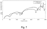
- the proposed acoustic filter provides acoustic performance in similar level of conventional acoustic filter, as shown in figure (7 ) through transmission loss, reduction of the temperature in the suction chamber of 2.4 °C, reduction of the temperature on the cylinder wall of 11.2 °C and increased energy efficiency of at least 1.5%.
- the inventive concept revealed herein and exemplified in one or more forms was treated as industrial secret and was not previously revealed until the time of the deposit of the present patent application.
- Said industrial secret is an intangible asset of the Applicant.
- the possible future publication of the patent application do not constitute authorization of use by third parties, serving only as: (i) notification to the third parties of the existence of said industrial secret at date of filing; (ii) clear indication of its Applicant; and (iii) encouraging the development of new improvements from the concept revealed herein, to prevent the reinvestment in the development of the already held by the Applicant.
- any eventual commercial use requires authorization from the Applicant and that the unauthorized use imposes penalties provided in the Law.
Landscapes
- Engineering & Computer Science (AREA)
- Mechanical Engineering (AREA)
- General Engineering & Computer Science (AREA)
- Compressor (AREA)
Abstract
The present invention lies in the field of mechanical engineering and describes a discharge acoustic filter. Specifically, the present invention comprises a discharge acoustic filter, optionally made of polymeric material in which the connections between the discharge chambers are internally disposed, in order to reduce the surface area of the discharge acoustic filter, reducing heat exchange in relation to the hermetic volume, thus, increasing thermal efficiency and reducing the energy consumption of the system.
Description
- The present invention lies in the field of mechanical engineering. More specifically, the present invention describes a discharge acoustic filter made of polymeric material that has the interconnections of expansion chambers through internal ducts.
- Discharge acoustic filters are already widely used coupled to compressors for reducing pulses generated by the compressors. Discharge acoustic filters are generally made of steel, which can be stamped and machined, which have a wide variety of parts, and can be made integrated to the cast iron block. However, discharge acoustic filters made of steel are large, heavy and present a large surface area that increases the heat exchange between the compressor and the hermetic volume.
- Discharge acoustic filters made of steel have a greater complexity of assembly, because the tubes that make the connections between the expansion chambers, the cylinder cover and the remaining of the system are made of copper and are assembled by brazing and must be conformed in specific formats.
- In the present invention, it was developed a solution to many of these and other technical problems. In one aspect, the discharge acoustic filter of the invention is made of polymeric material, which reduces the weight of the assembly. In other aspects, it is also provided solutions to reduce the size (compact acoustic filter) and to offer attenuation of pulses with the desired use.
- In the search for prior art in patent and scientific literature, only partially relevant documents were found, and described below:
- The
EP 2 725 228 - The
US 8,246,320 document discloses an acoustic filter or suction muffler with two expansion chambers and a connecting tube that connects the second chamber to the muffler outlet. The technical solution proposed is intended to reduce the loss of suction load, minimize the pulse and improve the cooling capacity of the system. - What is clear from the searched literature is that it was not found documents anticipating or suggesting the teachings of the present invention, so that the solution proposed herein, in the eyes of inventors, presents novelty and inventive activity in view of the state of the art.
- In view of all the documents found, there is still the need for a more compact discharge acoustic filter and which has technical features such as pulses attenuation capacity generated by the compressors.
- The present invention aims to solve the problems found in the state of the art from a compact discharge acoustic filter that integrates the cylinder cover and discharge chambers in a unique device/equipment.
- The inventive concept common to all contexts of protection claimed is the integration of a compact acoustic filter with pipes that connect an expansion chamber to another, where the said pipes are internally arranged in the acoustic filter. Additionally, the acoustic filter of the present invention is, optionally, made entirely of polymeric material.
- In a first aspect, the present invention presents an acoustic filter with compact structure and internal pipe. The surface area is smaller, reducing the heat exchange with the hermetic volume, a fact that reduces the temperature of the assembly. The acoustic filter also increases the efficiency of the cooling system and also reduces the energy expenditure.
- In another aspect, the present invention provides a discharge acoustic filter having lower weight, being entirely of polymeric material, both in chambers and in the internal pipes. The structure of acoustic filter does not use or require metal pipes and provides facilitated mounting of assembly. Additionally, it discards the need for extra assembling processes (such as brazing, gluing, welding, interference tec) and tube forming.
- In a first object, the invention provides a discharge acoustic filter comprising:
- a. at least a first element (1), comprising:
- i. at least one first discharge chamber (4);
- ii. a part of a second discharge chamber (5a);
- iii. a part of a third discharge chamber (6a);
- iv. a part of a fourth discharge chamber (7a);
- v. a first duct (8) connecting the first discharge chamber (4) to the second discharge chamber (5); and
- vi. a part of a third duct (10a) connecting the third discharge chamber (6) to the fourth discharge chamber (7);
- b. at least a second element (2), comprising:
- i. a part of a second discharge chamber (5b);
- ii. a part of a third discharge chamber (6b);
- iii. a part of a fourth discharge chamber (7b)
- iv. a part of a third duct (10b) connecting the third discharge chamber (6) to the fourth discharge chamber (7); and
- v. a portion of a second duct (9b) connecting the second discharge chamber (5) to the third discharge chamber (6);
- c. at least a third element (3), being:
- i. associated with the part of the second duct (9b);
- ii. connecting the second discharge chamber (5) to the third discharge chamber (6);
- In a second object, the present invention presents a manufacturing process of a discharge acoustic filter comprising the steps of:
- a. manufacture of a first element (1), by the steps of:
- b. manufacture of a second element (2), by the steps of:
- c. positioning of a third element (3) to the second element; and
- d. assembly of the first element (1) to the second element (2).
- In a third object, the invention provides a hermetic compressor comprising discharge acoustic filter which comprises:
- a. a cylinder cover (11) of compressor comprising at least a first discharge chamber (4);
- b. an intermediate region formed by the association of a first element (1) with a second element (2) and a third element (3); wherein,
- the intermediate region is comprised by the association of at least a second discharge chamber (5), at least a third discharge chamber (6) and at least a fourth discharge chamber (7);
- the discharge chambers of the intermediate region are fluidly communicating with each other.
- In one aspect, the compressor of the present invention provides greater energy efficiency, lowest temperature in hermetic volume, less weight and greater simplicity of manufacture and/or assembly. In addition, the reduced weight of the acoustic filter helps in reducing weight imbalances of the assembly, reducing vibrations on the compressor.
- These and other objects of the invention will be immediately appreciated by those skilled in art and by companies having interests in the segment, and will be described in sufficient details for their reproduction in the following description.
- In order to better define the content of the present invention, the following figures are presented:
-
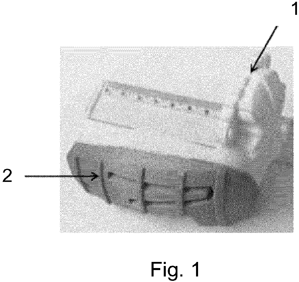
Figure 1 shows an image of an embodiment of a discharge acoustic filter mounted. -
Figure 2 shows an image of the first element (1) of an embodiment of discharge acoustic filter. -
Figure 3 shows an image of the second element (2) of an embodiment of discharge acoustic filter. -
Figure 4 shows an image of the first element (1) of an embodiment of discharge acoustic filter. -
Figure 5 shows an image of an embodiment of hermetic compressor comprising the discharge acoustic filter. -
Figure 6 shows an image of the state of the art compressor, the chambers of the metallic discharge acoustic filter and the metallic tubes, which connects them, being visible. -
Figure 7 compares the acoustic performance of the proposed filter by transmission loss with respect to the state of the art. - The examples shown herein are intended only to illustrate a few among many other ways to achieve the invention, without harming its scope.
- The present invention presents a discharge acoustic filter that is used for pulses attenuation generated by the compressor. The acoustic filter of the invention is compact, integrates the cylinder cover and comprises internally disposed ducts/pipes of passage of fluids. The acoustic filter of the invention is particularly useful for compressors, hermetic compressors and/or reciprocating hermetic compressors.
- In one embodiment, the acoustic filter is entirely made of polymeric material, being formed by a first element (1) associated with the second element (2), in addition to the third element (3), internally disposed in the acoustic filter. The association of the first element (1) with the second element (2) forms the discharge chambers, wherein every connection between discharge chambers is internal.
- In one embodiment, the discharge acoustic filter of the present invention comprises three elements:
- a first element (1) having a cylinder cover (11) of the compressor with a first discharge chamber (4), comprising a part of a second discharge chamber (5a), a part of a third discharge chamber (6a) and part of a fourth discharge chamber (7a);
- a second element (2) having a part of a second discharge chamber (5b), a part of a third discharge chamber (6b) and part of a fourth discharge chamber (7b), where all of them are interconnected, the said element also comprising an internal extension as being a part of a second duct (9b), in the coupling of the mentioned elements, the formed parts coincidentally unite, being formed the discharge chambers; and
- a third element (3) that is a duct for passage of the fluid.
- In one embodiment, the first element (1) is formed by a cylinder cover (11) with a first discharge chamber (5). By discharge chamber means that are hollow volumes between the walls, which provide the gas expansion that passes by it. A first duct (8) of passage of fluid connects the first discharge chamber (4) to the second discharge chamber (5). The second discharge chamber (5) is also interconnected to third discharge chamber (6), so that both are separated by means of divisional elements, as well as dividers partitions, being both fluidly communicating.
- The second element (2) is formed by a part of a second discharge chamber (5b), the part of a third discharge chamber (6b) and the part of a fourth discharge chamber (7b), so that it comprises a part of a second duct (9b) formed in an internal extension thereof, connecting the third discharge chamber (6) to the fourth discharge chamber (7). Moreover, the second element (2) comprises a part of a third duct (10b) connecting the second discharge chamber (5) to the third discharge chamber (6), wherein when the parts pertinent to the ducts, when associated, the part of the duct of the first element (1) and to the third element (3) form ducts internally disposed in the discharge acoustic filter proposed by the present invention. The duct is an element of any material and format that allows integration and passage of fluid between the discharge chambers.
- The third element (3), placed in part of the second duct (9b) in such a way as to form a second duct (9) itself, in which connects the second discharge chambers (5) to the third discharge chambers (6), so that both are fluidly communicating. In this way, the outlet fluid of the compressor flows through the first discharge chamber (4), and through the first duct (8), the fluid is poured into the second chamber (5), which in turn interconnects to the third chamber (6) through the duct (3) and thus, the fluid is conveyed to the fourth chamber (7) by means of the third duct (10), formed by the association between a first part of a third duct (10a) with a second part of a third duct (10b). In this sense, the discharge acoustic filter of the present invention comprises the interconnection between the discharge chambers through internal ducts to the acoustic filter itself, not requiring external ducts occupying utile area inside the compressor.
- The connections between the discharge chambers of the discharge acoustic filter are internally disposed in order to make the acoustic filter more compact, reducing its external surface, consequently reducing the heat exchange with the hermetic volume.
- In another embodiment, the discharge acoustic filter comprises an additional discharge chamber, formed by the association of an intermediate region in the first element (1) with an intermediate portion in the second element (2). With that, the pulses attenuation is improved. In this way, the acoustic filter proposed in the present invention allows to be implemented with different amounts of discharge chambers internally disposed and fluidly communicating. In one example, the discharge acoustic filter was implemented, as described, with four discharge chambers. Furthermore, in another example, the said acoustic filter was implemented with three discharge chambers.
- In one embodiment, the manufacturing process of the acoustic filter comprises the production of all the elements, separately, and according to its geometry. After the manufacture of all elements, the third element (3) is placed in the extension of the second element (2) and in sequence it occurs the assemble of the first (1) with the second element (2).
- The manufacture of the first element (1) occurs through the steps that are performed simultaneously: the manufacture of a compressor cylinder cover (11), the manufacture of the first discharge chamber (4), the manufacture of a first part of a second discharge chamber (5a), making a first part of a third discharge chamber (6a) and the manufacture of a first part of a fourth discharge chamber (7a), in addition to the manufacture of a first duct (8) connecting the first discharge chamber (4) to the second discharge chamber (5).
- The manufacture of the second element (2) occurs through the steps that are performed simultaneously: the manufacture of a second part of a second discharge chamber (5a), the manufacture of a second part of a third discharge chamber (6a) and the manufacture of a second part of a fourth discharge chamber (7a).
- In addition, for fixation of the first element (1) to the second element (2), it is preferably used at least one of the forms, being: ultrasonic welding, by means of adhesive material, induction welding, welding via laser, overinjection, among other methods, not restrictive to the cited ones.
- Another object of the present invention is a hermetic compressor comprising the discharge acoustic filter of the invention. The acoustic filter is as described above, comprising: a compressor cylinder cover comprising at least a first discharge chamber; an intermediate region formed by the association of the first element (1) with the second element (2) and the third element (3). Furthermore, the intermediate region is comprised by the association of at least a second discharge chamber (5), at least a third discharge chamber (6) and at least a fourth discharge chamber (7), where the chambers are fluidly communicating.
- In the discharge acoustic filter of the compressor, the second element (2) comprises a portion of a second duct (9b), so as the third discharge chamber (6) is fluidly communicating with the fourth discharge chamber (7), through a duct (3) of fluid passage, positioned in said part of the second duct (9b), in the second element (2).
- The proposed acoustic filter provides acoustic performance in similar level of conventional acoustic filter, as shown in
figure (7 ) through transmission loss, reduction of the temperature in the suction chamber of 2.4 °C, reduction of the temperature on the cylinder wall of 11.2 °C and increased energy efficiency of at least 1.5%. - The inventive concept revealed herein and exemplified in one or more forms was treated as industrial secret and was not previously revealed until the time of the deposit of the present patent application. Said industrial secret is an intangible asset of the Applicant. The possible future publication of the patent application do not constitute authorization of use by third parties, serving only as: (i) notification to the third parties of the existence of said industrial secret at date of filing; (ii) clear indication of its Applicant; and (iii) encouraging the development of new improvements from the concept revealed herein, to prevent the reinvestment in the development of the already held by the Applicant. Thus, it is advised that any eventual commercial use requires authorization from the Applicant and that the unauthorized use imposes penalties provided in the Law. In this context, it is clarified that from the disclosure of the present inventive concept, those skilled in art may consider other ways of achieving the invention not identical to the merely exemplified above, but in the event of claiming commercial use, such forms can be considered as being within the scope of the attached claims.
Claims (7)
- DISCHARGE ACOUSTIC FILTER FOR HERMETIC COMPRESSORS, characterized by the fact that it comprises:a. at least a first element (1), which comprises:i. at least one first discharge chamber (4);ii. a part of a second discharge chamber (5a);iii. a part of a third discharge chamber (6a);iv. a part of a fourth discharge chamber (7a);v. a first duct (8) connecting the first discharge chamber (4) to the second discharge chamber (5); andvi. a part of a third duct (10a) connecting the third discharge chamber (6) to the fourth discharge chamber (7);b. at least a second element (2) comprising:i. a part of a second discharge chamber (5b);ii. a part of a third discharge chamber (6b);iii. a part of a fourth discharge chamber (7b);iv. a part of a third duct (10b) connecting the third discharge chamber (6) to the fourth discharge chamber (6); andv. a part of a second duct (9b) connecting the second discharge chamber (5) to the third discharge chamber (6);c. at least a third element (3), being:wherein, the first element (1) is associated with the second element (2) and with the third element (3).i. associated in part of the second duct (9b);ii. connecting the second discharge chamber (5) to the third discharge chamber (6);
- ACOUSTIC FILTER, according to claim 1, characterized by the fact that the first element (1) comprises at least one compressor cylinder cover (11).
- MANUFACTURING PROCESS OF DISCHARGE ACOUSTIC FILTER FOR HERMETIC COMPRESSORS, characterized by the fact that it comprises the steps of:a. manufacture of a first element (1);b. manufacture of a second element (2);c. positioning of a third element (3) to the second element (2); andd. assembling the first element (1) to the second element (2).
- MANUFACTURING PROCESS OF DISCHARGE ACOUSTIC FILTER according to claim 3, characterized by the fact that the manufacture of a first element (1) comprises the steps of:a. manufacture of a cylinder cover of compressor (11);b. manufacture of a first discharge chamber (4); andc. manufacture of a first part of a second discharge chamber (5a);d. manufacture of a first part of a third discharge chamber (6a);e. manufacture of a first part of a fourth discharge chamber (7a);f. manufacture of a first duct (8) connecting the first discharge chamber (4) to the second discharge chamber (5).
- MANUFACTURING PROCESS OF DISCHARGE ACOUSTIC FILTER, according to claim 3, characterized by the fact that the manufacture of the second element (2) comprises the steps of:a. manufacture of a second part of a second discharge chamber (5a);b. manufacture of a second part of a third discharge chamber (6a);c. manufacture of a second part of a fourth discharge chamber (7a).
- MANUFACTURING PROCESS OF DISCHARGE ACOUSTIC FILTER, according to any one of claims 3 to 5, characterized by the fact that the steps of manufacture of the first element (1) and/or the steps of manufacture of the second element (2) occur at the same time.
- HERMETIC COMPRESSOR COMPRISING DISCHARGE ACOUSTIC FILTER, characterized by the fact that the said discharge acoustic filter comprises:a. a cylinder cover (11) of compressor comprising at least a first discharge chamber (4);b. an intermediate region formed by the association of a first element (1) with a second element (2) and a third element (3); wherein,- the intermediate region comprises the association of at least a second discharge chamber (5), at least a third discharge chamber (6) and at least a fourth discharge chamber (7);- the discharge chambers of the intermediate region are fluidly communicating.
Applications Claiming Priority (1)
| Application Number | Priority Date | Filing Date | Title |
|---|---|---|---|
| BR102016005387-0A BR102016005387A2 (en) | 2016-03-11 | 2016-03-11 | DISCHARGE ACOUSTIC FILTER, PROCESS OF MANUFACTURE OF ACOUSTIC DISCHARGE FILTER AND HERMETIC COMPRESSOR |
Publications (1)
| Publication Number | Publication Date |
|---|---|
| EP3217012A1 true EP3217012A1 (en) | 2017-09-13 |
Family
ID=58266936
Family Applications (1)
| Application Number | Title | Priority Date | Filing Date |
|---|---|---|---|
| EP17160173.5A Withdrawn EP3217012A1 (en) | 2016-03-11 | 2017-03-09 | Discharge acoustic filter, manufacturing process of discharge acoustic filter and hermetic compressor |
Country Status (5)
| Country | Link |
|---|---|
| US (1) | US20170260974A1 (en) |
| EP (1) | EP3217012A1 (en) |
| JP (1) | JP2017160908A (en) |
| CN (1) | CN107178483A (en) |
| BR (1) | BR102016005387A2 (en) |
Cited By (1)
| Publication number | Priority date | Publication date | Assignee | Title |
|---|---|---|---|---|
| EP4170168A1 (en) * | 2021-10-25 | 2023-04-26 | Secop GmbH | Discharge muffler for a refrigerant compressor |
Families Citing this family (1)
| Publication number | Priority date | Publication date | Assignee | Title |
|---|---|---|---|---|
| WO2021119794A1 (en) * | 2019-12-19 | 2021-06-24 | Embraco Indústria De Compressores E Soluções Em Refrigeração Ltda. | Reciprocating compressor cylinder cover |
Citations (8)
| Publication number | Priority date | Publication date | Assignee | Title |
|---|---|---|---|---|
| US3202344A (en) * | 1962-08-10 | 1965-08-24 | Danfoss Ved Ing M Clausen | Piston compressor, especially for refrigeration |
| US3600110A (en) * | 1968-03-16 | 1971-08-17 | Danfoss As | Hermetically enclosed refrigerating machine |
| GB2224314A (en) * | 1986-07-09 | 1990-05-02 | Danfoss As | A sound dampener for use in a refrigeration compressor |
| KR100681458B1 (en) * | 2005-12-12 | 2007-02-09 | 주식회사 대우일렉트로닉스 | Discharge muffler of compressor |
| US8246320B2 (en) | 2008-03-04 | 2012-08-21 | Lg Electronics Inc. | Muffler for compressor |
| WO2014053040A1 (en) * | 2012-10-03 | 2014-04-10 | Whirlpool S.A. | Thermal insulation system for the discharge of gas in a refrigeration compressor |
| WO2014059504A1 (en) * | 2012-10-18 | 2014-04-24 | Whirlpool S.A . | Expansion chamber for alternative compressor discharge line |
| EP2725228A1 (en) | 2011-09-30 | 2014-04-30 | Huangshi Dongbei Electrical Appliance Co., Ltd. | Discrete heat-insulated exhaust muffler device and refrigeration compressor using same |
-
2016
- 2016-03-11 BR BR102016005387-0A patent/BR102016005387A2/en not_active Application Discontinuation
-
2017
- 2017-03-07 JP JP2017042447A patent/JP2017160908A/en active Pending
- 2017-03-08 US US15/453,344 patent/US20170260974A1/en not_active Abandoned
- 2017-03-09 EP EP17160173.5A patent/EP3217012A1/en not_active Withdrawn
- 2017-03-13 CN CN201710144453.5A patent/CN107178483A/en active Pending
Patent Citations (8)
| Publication number | Priority date | Publication date | Assignee | Title |
|---|---|---|---|---|
| US3202344A (en) * | 1962-08-10 | 1965-08-24 | Danfoss Ved Ing M Clausen | Piston compressor, especially for refrigeration |
| US3600110A (en) * | 1968-03-16 | 1971-08-17 | Danfoss As | Hermetically enclosed refrigerating machine |
| GB2224314A (en) * | 1986-07-09 | 1990-05-02 | Danfoss As | A sound dampener for use in a refrigeration compressor |
| KR100681458B1 (en) * | 2005-12-12 | 2007-02-09 | 주식회사 대우일렉트로닉스 | Discharge muffler of compressor |
| US8246320B2 (en) | 2008-03-04 | 2012-08-21 | Lg Electronics Inc. | Muffler for compressor |
| EP2725228A1 (en) | 2011-09-30 | 2014-04-30 | Huangshi Dongbei Electrical Appliance Co., Ltd. | Discrete heat-insulated exhaust muffler device and refrigeration compressor using same |
| WO2014053040A1 (en) * | 2012-10-03 | 2014-04-10 | Whirlpool S.A. | Thermal insulation system for the discharge of gas in a refrigeration compressor |
| WO2014059504A1 (en) * | 2012-10-18 | 2014-04-24 | Whirlpool S.A . | Expansion chamber for alternative compressor discharge line |
Cited By (1)
| Publication number | Priority date | Publication date | Assignee | Title |
|---|---|---|---|---|
| EP4170168A1 (en) * | 2021-10-25 | 2023-04-26 | Secop GmbH | Discharge muffler for a refrigerant compressor |
Also Published As
| Publication number | Publication date |
|---|---|
| BR102016005387A2 (en) | 2017-09-19 |
| US20170260974A1 (en) | 2017-09-14 |
| JP2017160908A (en) | 2017-09-14 |
| CN107178483A (en) | 2017-09-19 |
Similar Documents
| Publication | Publication Date | Title |
|---|---|---|
| US8573287B2 (en) | Plate heat exchanger | |
| AU656464B2 (en) | High pressure, long life, aluminum heat exchanger construction | |
| CN100540110C (en) | Combined filter-cooler for fluids, in particular for lubricating oils of internal combustion engines of motor vehicles | |
| JP3427526B2 (en) | Oil cooler | |
| CN102971533B (en) | Exhaust muffler for hermetically encapsulated refrigerant compressor | |
| CN108204353B (en) | Closed compressor | |
| IT8267560A1 (en) | HERMETIC COMPRESSOR FOR REFRIGERATION SYSTEMS WITH IMPROVED SILENCER DEVICE | |
| EP3217012A1 (en) | Discharge acoustic filter, manufacturing process of discharge acoustic filter and hermetic compressor | |
| EP3161403A1 (en) | Heat exchanger with reinforced header plate | |
| JPWO2017212743A1 (en) | Laminate heat exchanger | |
| EP3047145B1 (en) | Suction muffler for hermetic compressor | |
| EP4160129A1 (en) | Heat management apparatus and heat management system | |
| CN117366922A (en) | Economizer and refrigerating system with same | |
| CN221881841U (en) | Pipeline integrated module, outdoor unit and air conditioning system | |
| CN210118237U (en) | Noise elimination structure of compressor | |
| KR101940489B1 (en) | Linear compressor | |
| JP2002070778A (en) | Screw compressor | |
| JP2017194230A (en) | Refrigerant flow diverter connection type expansion valve, freezing cycle device using this expansion valve and air conditioner | |
| EP3956621A1 (en) | Support and connection device | |
| EP3336355B1 (en) | Hermetic compressor | |
| EP1771660B1 (en) | A compressor | |
| CN210154388U (en) | a heat exchanger | |
| EP1730402B1 (en) | Compressor with suction muffler | |
| CN112145432A (en) | Pump body structure and compressor having the same | |
| CN109028347B (en) | Compressor and air conditioner using same |
Legal Events
| Date | Code | Title | Description |
|---|---|---|---|
| PUAI | Public reference made under article 153(3) epc to a published international application that has entered the european phase |
Free format text: ORIGINAL CODE: 0009012 |
|
| AK | Designated contracting states |
Kind code of ref document: A1 Designated state(s): AL AT BE BG CH CY CZ DE DK EE ES FI FR GB GR HR HU IE IS IT LI LT LU LV MC MK MT NL NO PL PT RO RS SE SI SK SM TR |
|
| AX | Request for extension of the european patent |
Extension state: BA ME |
|
| STAA | Information on the status of an ep patent application or granted ep patent |
Free format text: STATUS: THE APPLICATION IS DEEMED TO BE WITHDRAWN |
|
| 18D | Application deemed to be withdrawn |
Effective date: 20180314 |