EP3217007A1 - Ventil zur gleichzeitigen regelung von zwei fluidströmen, insbesondere für die dosierung von rückgeführten gasen in einem verbrennungsmotor - Google Patents
Ventil zur gleichzeitigen regelung von zwei fluidströmen, insbesondere für die dosierung von rückgeführten gasen in einem verbrennungsmotor Download PDFInfo
- Publication number
- EP3217007A1 EP3217007A1 EP17150600.9A EP17150600A EP3217007A1 EP 3217007 A1 EP3217007 A1 EP 3217007A1 EP 17150600 A EP17150600 A EP 17150600A EP 3217007 A1 EP3217007 A1 EP 3217007A1
- Authority
- EP
- European Patent Office
- Prior art keywords
- groove
- axis
- plug
- fluid inlet
- inlet
- Prior art date
- Legal status (The legal status is an assumption and is not a legal conclusion. Google has not performed a legal analysis and makes no representation as to the accuracy of the status listed.)
- Granted
Links
- 239000007789 gas Substances 0.000 title claims abstract description 38
- 238000002485 combustion reaction Methods 0.000 title claims abstract description 10
- 239000012530 fluid Substances 0.000 title claims description 90
- 239000003546 flue gas Substances 0.000 claims abstract description 10
- UGFAIRIUMAVXCW-UHFFFAOYSA-N Carbon monoxide Chemical compound [O+]#[C-] UGFAIRIUMAVXCW-UHFFFAOYSA-N 0.000 claims abstract description 8
- 238000011144 upstream manufacturing Methods 0.000 claims abstract description 3
- 238000011084 recovery Methods 0.000 claims description 3
- 230000001105 regulatory effect Effects 0.000 claims description 2
- 238000005553 drilling Methods 0.000 description 8
- 239000000203 mixture Substances 0.000 description 3
- 238000002347 injection Methods 0.000 description 1
- 239000007924 injection Substances 0.000 description 1
- 239000007788 liquid Substances 0.000 description 1
Images
Classifications
-
- F—MECHANICAL ENGINEERING; LIGHTING; HEATING; WEAPONS; BLASTING
- F02—COMBUSTION ENGINES; HOT-GAS OR COMBUSTION-PRODUCT ENGINE PLANTS
- F02M—SUPPLYING COMBUSTION ENGINES IN GENERAL WITH COMBUSTIBLE MIXTURES OR CONSTITUENTS THEREOF
- F02M26/00—Engine-pertinent apparatus for adding exhaust gases to combustion-air, main fuel or fuel-air mixture, e.g. by exhaust gas recirculation [EGR] systems
- F02M26/52—Systems for actuating EGR valves
- F02M26/64—Systems for actuating EGR valves the EGR valve being operated together with an intake air throttle
-
- F—MECHANICAL ENGINEERING; LIGHTING; HEATING; WEAPONS; BLASTING
- F02—COMBUSTION ENGINES; HOT-GAS OR COMBUSTION-PRODUCT ENGINE PLANTS
- F02M—SUPPLYING COMBUSTION ENGINES IN GENERAL WITH COMBUSTIBLE MIXTURES OR CONSTITUENTS THEREOF
- F02M26/00—Engine-pertinent apparatus for adding exhaust gases to combustion-air, main fuel or fuel-air mixture, e.g. by exhaust gas recirculation [EGR] systems
- F02M26/65—Constructional details of EGR valves
- F02M26/70—Flap valves; Rotary valves; Sliding valves; Resilient valves
-
- F—MECHANICAL ENGINEERING; LIGHTING; HEATING; WEAPONS; BLASTING
- F16—ENGINEERING ELEMENTS AND UNITS; GENERAL MEASURES FOR PRODUCING AND MAINTAINING EFFECTIVE FUNCTIONING OF MACHINES OR INSTALLATIONS; THERMAL INSULATION IN GENERAL
- F16K—VALVES; TAPS; COCKS; ACTUATING-FLOATS; DEVICES FOR VENTING OR AERATING
- F16K11/00—Multiple-way valves, e.g. mixing valves; Pipe fittings incorporating such valves
- F16K11/02—Multiple-way valves, e.g. mixing valves; Pipe fittings incorporating such valves with all movable sealing faces moving as one unit
- F16K11/06—Multiple-way valves, e.g. mixing valves; Pipe fittings incorporating such valves with all movable sealing faces moving as one unit comprising only sliding valves, i.e. sliding closure elements
- F16K11/072—Multiple-way valves, e.g. mixing valves; Pipe fittings incorporating such valves with all movable sealing faces moving as one unit comprising only sliding valves, i.e. sliding closure elements with pivoted closure members
- F16K11/076—Multiple-way valves, e.g. mixing valves; Pipe fittings incorporating such valves with all movable sealing faces moving as one unit comprising only sliding valves, i.e. sliding closure elements with pivoted closure members with sealing faces shaped as surfaces of solids of revolution
-
- F—MECHANICAL ENGINEERING; LIGHTING; HEATING; WEAPONS; BLASTING
- F02—COMBUSTION ENGINES; HOT-GAS OR COMBUSTION-PRODUCT ENGINE PLANTS
- F02D—CONTROLLING COMBUSTION ENGINES
- F02D9/00—Controlling engines by throttling air or fuel-and-air induction conduits or exhaust conduits
- F02D9/02—Controlling engines by throttling air or fuel-and-air induction conduits or exhaust conduits concerning induction conduits
- F02D2009/0201—Arrangements; Control features; Details thereof
- F02D2009/0276—Throttle and EGR-valve operated together
-
- F—MECHANICAL ENGINEERING; LIGHTING; HEATING; WEAPONS; BLASTING
- F02—COMBUSTION ENGINES; HOT-GAS OR COMBUSTION-PRODUCT ENGINE PLANTS
- F02D—CONTROLLING COMBUSTION ENGINES
- F02D9/00—Controlling engines by throttling air or fuel-and-air induction conduits or exhaust conduits
- F02D9/08—Throttle valves specially adapted therefor; Arrangements of such valves in conduits
- F02D9/12—Throttle valves specially adapted therefor; Arrangements of such valves in conduits having slidably-mounted valve members; having valve members movable longitudinally of conduit
- F02D9/16—Throttle valves specially adapted therefor; Arrangements of such valves in conduits having slidably-mounted valve members; having valve members movable longitudinally of conduit the members being rotatable
-
- F—MECHANICAL ENGINEERING; LIGHTING; HEATING; WEAPONS; BLASTING
- F02—COMBUSTION ENGINES; HOT-GAS OR COMBUSTION-PRODUCT ENGINE PLANTS
- F02M—SUPPLYING COMBUSTION ENGINES IN GENERAL WITH COMBUSTIBLE MIXTURES OR CONSTITUENTS THEREOF
- F02M26/00—Engine-pertinent apparatus for adding exhaust gases to combustion-air, main fuel or fuel-air mixture, e.g. by exhaust gas recirculation [EGR] systems
- F02M26/51—EGR valves combined with other devices, e.g. with intake valves or compressors
Definitions
- the subject of the invention is the internal combustion engines, and more specifically the internal combustion engines with recirculation of the burnt gases.
- a portion of the burnt gases leaving the engine cylinders can be returned to the engine air manifold to change the combustion conditions of the engine.
- This recirculation system is often referred to by the acronym "EGR" (Exhaust Gas Recirculation), and recirculated gases are often referred to as EGR gases.
- a first valve for example a flap valve
- a second valve may also be used, for example a flapper valve, to regulate the flow of EGR gas.
- Two valves and two actuators are used. At least one of the valves is further subjected to high temperatures because it is traversed by the flue gases.
- a first gas metering system reinjected into the engine is presented in the publication US 6,062,205 A .
- the system presented does not allow a combination of fresh air and reinjected burned gases.
- EP 2 333 289-B1 discloses a mixing valve for fresh air and exhausted exhaust gases.
- the described dosing system only allows two operating positions. This is how when the fresh air butterfly is in open position, the EGR inlet is closed, which does not allow a true continuous mixing of the two gases.
- the invention aims to provide a system for dosing the proportion of recirculated gas returned to the engine, the system being simpler to produce, cheaper and more reliable than existing two-valve systems.
- the fresh air inlet and the flue gas inlet open into the same rotary valve, whose outlet is connected to an intake manifold of the engine, the fresh air inlet and the gas inlet. recirculated being axially offset relative to each other along the axis of rotation of the plug.
- the outlet to the intake manifold and the recirculated gas inlet are offset axially relative to each other along the axis of rotation of the plug.
- the valve preferably comprises only one rotary plug.
- the outlet of the valve can be connected directly or indirectly to the intake manifold through other elements interposed in the fluid path, such as a cooler for example.
- the power plant may include a fluid outlet from the plug valve to the engine intake manifold, the flow direction at the fluid outlet being substantially aligned with the fresh air supply.
- the flow directions at the inlet and at the fluid outlet may be parallel and substantially coaxial.
- the flow directions of the arrival and the fluid outlet can be aligned in the broad sense of the term, the two directions being non-parallel but extending substantially to the same point, inside the valve.
- the rotary plug comprises a groove dug on the surface of the plug to allow simultaneous entry of recirculated flue gas and fresh air into the groove.
- the groove thus disposed contributes to a simultaneous outlet of recirculated burnt gases and fresh air to the intake manifold.
- the plug may comprise for that a control groove connected to the groove and extending at least partly transversely to the axis of rotation of the plug.
- the groove is arranged so that, for at least one angular position of the plug, it is possible to connect the groove simultaneously with the recirculated flue gas inlet and the fresh air inlet.
- the groove may for this purpose extend axially between the fresh air inlet and the recirculated flue gas inlet (or, in an equivalent embodiment, extend axially between the recirculated flue gas inlet and the outlet to the intake manifold).
- valve system further comprising a plug mounted within the housing to be rotatable about an axis of the valve,
- the plug being pierced, transversely to the axis, of a regulating groove placed so as to be successively, as a function of the angular position of the plug around the axis, aligned in varying degrees with the first fluid inlet, so as to provide an effective section of variable passage between the first fluid inlet and the first fluid outlet.
- the second fluid inlet being offset axially with respect to the first fluid inlet and with respect to the control groove, and the surface of the plug being hollowed out with a groove extending parallel to the axis, between the control groove and the axial position of the second fluid inlet, the groove communicating with the control groove, the position and the width angular of the groove being chosen so as to successively, depending on the angular position of the plug around the axis, isolate the second fluid inlet of the groove and the control groove, then cause the second fluid inlet to open variable in the groove.
- the angular width of the groove may be greater than or equal to the angular width of the second fluid inlet.
- the flow axis joining the first fluid inlet and the first fluid outlet may be eccentric relative to the axis of rotation of the plug.
- the control groove is for example obtained by performing a cylindrical bore through the plug.
- the drilling axis is preferably perpendicular to the axis of rotation of the plug.
- the drilling axis is preferably eccentric with respect to the axis of rotation of the plug.
- the drilling axis is disposed obliquely to the axis of rotation of the plug.
- the first fluid inlet and the first fluid outlet are substantially cylindrical. Their diameters may advantageously differ from each other by less than 10% with respect to the throat drilling diameter.
- the central housing of the casing surrounding the outer surface of the plug is substantially cylindrical.
- the groove may have a radial depth less than or equal to one quarter of the diameter of the plug.
- the first fluid inlet is angularly offset about the axis of rotation of the plug relative to the second fluid inlet, of an angular value such as during the rotation of the plug, at the beginning of the partial recovery of the groove with the second fluid inlet, the axis of the control groove is inclined in a first direction with respect to a common axis of the first fluid inlet and the first fluid outlet, and at the end of the total recovery the second fluid inlet by the groove, the axis of the control groove is inclined in a second direction opposite to the first direction, relative to the common axis of the first fluid inlet and the first fluid outlet.
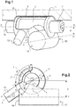
- a fresh air supply line of a motor vehicle engine passes through a valve housing 4, arriving by a first inlet 12 of fluid entering the housing, and out of a first outlet 14 outgoing fluid of the casing, substantially aligned with the first arrival 12.
- the first inlet 12 and the first outlet 14 are substantially aligned, are of cylindrical section, and are substantially of the same diameter. It is possible to envisage variant embodiments with different inlet and outlet sections, as well as a possible angle between the inlet pipe and the outlet pipe leaving the casing 4.
- a second inlet fluid fluid 13 axially offset relative to the first fluid inlet 12 and the first fluid outlet 14.
- the second fluid inlet 13 may serve typically to bring a flow of EGR gas into the valve, and as such connected to a exhaust gas recirculation pipeline.
- the section of the second fluid inlet may be smaller than the section of the first fluid inlet, while remaining of comparable size, for example may be between 0.2 and 1 times the section of the first fluid inlet.
- a cylindrical housing 5 inside which is installed a rotary plug 1, mounted so as to rotate about an axis XX which is subsequently designated as the axis of rotation of the valve.
- the casing 4 is here schematically represented as a massive part including the cylindrical housing 5.
- the casing 4 may have a much lower thickness than that shown, while being designed to define the cylindrical housing 5 accommodating the bushel 1 and its possible bearing system, and to define the first arrival 12, the second arrival 13, and the first exit 14 fluid with the necessary seals.
- the plug 1 is of generally cylindrical shape, and is supported at its two ends by bearings 11 for rotating it relative to the housing 4.
- the housing 4 also opens a second fluid inlet 13 shifted axially along the axis XX 'with respect to the first inlet 12 and the first outlet 14 of fluid.
- the cylindrical housing 5 of the housing 4 typically comprises an inner cylindrical surface 6 facing the plug 1, with a sufficiently small radial deviation with respect to the outer surface 7 corresponding to the cylindrical outer contour of the plug 1, to limit the flow of fluid between the surfaces cylindrical 6 and 7.
- a cylindrical bore forming a control groove 2 passes through the plug 1 in a direction substantially perpendicular to the axis XX 'of rotation of the valve.
- the axis YY 'corresponding to the common central axis of the first fluid inlet 12 and the first fluid outlet 14, is in a plane perpendicular to the axis of rotation XX'. It is possible to envisage variant embodiments in which the axis YY 'is not perpendicular to the axis XX'.
- the axis of the control groove 2 must then be adapted accordingly, for example to remain parallel to the axis YY '.
- the axis YY ' is separated by a distance "d" of eccentricity with respect to the axis XX' of rotation, and the axis of drilling of the groove 2 can also be eccentric with respect to the axis of rotation XX ', for example of a value substantially equal to "d".
- the diameter of drilling the groove 2 may advantageously be substantially equal to the diameter of a pipe formed by the alignment of the first inlet 12 and the first outlet 14, so that, for at least one angular position of the plug 1, the groove 2 is aligned with the fluid passage joining the inlet 12 and the outlet 14, without restricting the passage section of the inlet to the outlet.
- the plug 1 is in a position marked by an inclination ⁇ of the axis of the groove 2 relative to the axis YY 'for the passage of fresh air.
- the edges of the groove 2 of the plug 1 are partly inserted through the fresh air passage joining the inlet 12 to the outlet 14, while leaving more than half of the section of this passage available for the passage fresh air. If the plug 1 is rotated to bring the angle ⁇ to zero, the groove 2 is then aligned with the passage connecting the inlet 12 to the outlet 14, and the available section for the passage of fresh air is maximum . If we continue then to turn the plug 1, always in the same direction of rotation, a portion of the side walls of the groove 2 can come again to interpose in the fresh air passage of the pipe joining the entrance 12 and exit 14.
- a longitudinal groove 3 joining the control groove 2 and extending parallel to the axis XX 'to the second fluid inlet 13, so that a fluid arriving through this second arrival can flow into the groove.
- the groove 3 extends on the surface and on at least a portion of the radial depth of the bushel 1, has an angular width ⁇ (visible on the figure 2 ) and a radial depth "e".
- the angular width ⁇ of the groove is chosen to be greater than the angular width ⁇ of the second fluid inlet, so that, when the groove 3 faces the second fluid inlet 13, the entire section of the inlet 13 is facing a portion of the groove 3 of radial depth "e".
- the valve is evolved to other configurations increasing the available section for the passage of fresh air and allowing a partial passage of EGR gas through the second inlet 13.
- Embodiments with spherical plug shapes may also be envisaged, also comprising a bore perpendicular to the axis of rotation forming a control groove, and a groove parallel to the axis of rotation or extending at least partially to the direction parallel to the axis, and opening into the groove.
- the first fluid inlet, the second fluid inlet, the first fluid outlet are all on the same side of the same plane passing through the axis of rotation XX '.
- the first fluid inlet forms an angle around the axis XX 'with respect to the first fluid outlet, the regulation groove being pierced to form a corresponding angle.
- the arrival of burnt gases and the arrival of fresh air are angularly offset relative to each other about the axis of rotation of the bushel.
- the groove is substantially parallel to the axis of rotation of the plug.
- the groove may however not be parallel to the axis of rotation of the plug, for example may run along a helical portion about the axis of rotation of the plug. The arrival of flue gases and the arrival of fresh air can then possibly lead into the same angular sector of the bushel.
- the depth of the groove e, the diameters of the passageway from the inlet 12 to the outlet 14 and / or the diameter of the bore forming the groove 2 can be adapted to vary the desired relative flow rates between the EGR gas and the 'fresh air.
- the groove may not be strictly parallel to the axis XX '.
- a valve according to the invention makes it possible to regulate using the same valve and a single actuator the mixture of fresh air and EGR that is to be sent to the combustion chambers of the engine.
- a valve system according to the invention can be used to measure on the same principle mixtures of two liquid fluids or preferably gaseous, in other applications than the air supply of an engine.
Landscapes
- Engineering & Computer Science (AREA)
- General Engineering & Computer Science (AREA)
- Mechanical Engineering (AREA)
- Chemical & Material Sciences (AREA)
- Combustion & Propulsion (AREA)
- Exhaust-Gas Circulating Devices (AREA)
Applications Claiming Priority (1)
| Application Number | Priority Date | Filing Date | Title |
|---|---|---|---|
| FR1651918A FR3048732B1 (fr) | 2016-03-08 | 2016-03-08 | Vanne de modulation simultanee de deux flux fluide, notamment pour dosage de gaz recircules dans un moteur a combustion interne. |
Publications (2)
| Publication Number | Publication Date |
|---|---|
| EP3217007A1 true EP3217007A1 (de) | 2017-09-13 |
| EP3217007B1 EP3217007B1 (de) | 2018-08-15 |
Family
ID=55808714
Family Applications (1)
| Application Number | Title | Priority Date | Filing Date |
|---|---|---|---|
| EP17150600.9A Active EP3217007B1 (de) | 2016-03-08 | 2017-01-09 | Ventil zur gleichzeitigen regelung von zwei fluidströmen, insbesondere für die dosierung von rückgeführten gasen in einem verbrennungsmotor |
Country Status (2)
| Country | Link |
|---|---|
| EP (1) | EP3217007B1 (de) |
| FR (1) | FR3048732B1 (de) |
Citations (6)
| Publication number | Priority date | Publication date | Assignee | Title |
|---|---|---|---|---|
| DE19631337A1 (de) * | 1996-08-02 | 1998-02-05 | Audi Ag | Vorrichtung zur Abgasrückführung an einer Brennkraftmaschine |
| EP0887541A2 (de) * | 1997-06-25 | 1998-12-30 | Lucas Industries Public Limited Company | Abgasrückführungsventil |
| WO2008089985A1 (de) * | 2007-01-25 | 2008-07-31 | Edwards Lifesciences Iprm Ag | Multifunktionsventil |
| FR2928704A1 (fr) * | 2008-03-11 | 2009-09-18 | Peugeot Citroen Automobiles Sa | Dispositif repartiteur d'admission d'un moteur |
| EP2333289A2 (de) * | 2009-12-12 | 2011-06-15 | MAHLE International GmbH | Brennkraftmaschinensystem und zugehöriges Betriebsverfahren |
| EP2881571A1 (de) * | 2013-12-03 | 2015-06-10 | Valeo Systemes Thermiques | Vorrichtung zur Kontrolle eines einströmenden Gasflusses und/oder rückgeführten Abgasflusses in einem Zylinder eines Verbrennungsmotors, und entsprechendes Ansaugmodul |
-
2016
- 2016-03-08 FR FR1651918A patent/FR3048732B1/fr not_active Expired - Fee Related
-
2017
- 2017-01-09 EP EP17150600.9A patent/EP3217007B1/de active Active
Patent Citations (8)
| Publication number | Priority date | Publication date | Assignee | Title |
|---|---|---|---|---|
| DE19631337A1 (de) * | 1996-08-02 | 1998-02-05 | Audi Ag | Vorrichtung zur Abgasrückführung an einer Brennkraftmaschine |
| EP0887541A2 (de) * | 1997-06-25 | 1998-12-30 | Lucas Industries Public Limited Company | Abgasrückführungsventil |
| US6062205A (en) | 1997-06-25 | 2000-05-16 | Lucas Industries Plc | Valve assemblies |
| WO2008089985A1 (de) * | 2007-01-25 | 2008-07-31 | Edwards Lifesciences Iprm Ag | Multifunktionsventil |
| FR2928704A1 (fr) * | 2008-03-11 | 2009-09-18 | Peugeot Citroen Automobiles Sa | Dispositif repartiteur d'admission d'un moteur |
| EP2333289A2 (de) * | 2009-12-12 | 2011-06-15 | MAHLE International GmbH | Brennkraftmaschinensystem und zugehöriges Betriebsverfahren |
| EP2333289B1 (de) | 2009-12-12 | 2014-08-20 | MAHLE International GmbH | Brennkraftmaschinensystem und zugehöriges Betriebsverfahren |
| EP2881571A1 (de) * | 2013-12-03 | 2015-06-10 | Valeo Systemes Thermiques | Vorrichtung zur Kontrolle eines einströmenden Gasflusses und/oder rückgeführten Abgasflusses in einem Zylinder eines Verbrennungsmotors, und entsprechendes Ansaugmodul |
Also Published As
| Publication number | Publication date |
|---|---|
| EP3217007B1 (de) | 2018-08-15 |
| FR3048732B1 (fr) | 2018-03-09 |
| FR3048732A1 (fr) | 2017-09-15 |
Similar Documents
| Publication | Publication Date | Title |
|---|---|---|
| FR2990739A1 (fr) | Vanne pour commander la circulation de fluide, a moyen d'obturation rotatif | |
| WO2014122394A1 (fr) | Vanne de decharge et dispositif associe | |
| WO2014122389A1 (fr) | Système de suralimentation des gaz d'admission et de recirculation des gaz d'échappement d'un moteur et procédé de commande associé | |
| EP3217007B1 (de) | Ventil zur gleichzeitigen regelung von zwei fluidströmen, insbesondere für die dosierung von rückgeführten gasen in einem verbrennungsmotor | |
| FR2923886A1 (fr) | Vanne pour circuit d'alimentation en air d'un moteur de vehicule automobile, circuit comportant une telle vanne et procede de commande d'un moteur utilisant un tel circuit | |
| EP2831473B1 (de) | Durchflussventil | |
| EP1972798B1 (de) | Vorrichtung zur Positionssteuerung eines Stellglieds über ein Servoventil mit Positionsspeicher im Fall einer Panne | |
| EP1707781B1 (de) | Brennkraftmaschine mit einem Ventilsystem zur Regelung einer Abgasrückführrate und Kraftfahrzeug mit einer solchen Brennkraftmaschine. | |
| FR2910541A1 (fr) | Systeme d'admission de gaz pour la generation d'ecoulement de rotation energetique de tumble | |
| EP1188912B1 (de) | Luftansaugkanalsystem für eine Brennkraftmaschine | |
| FR3000169A1 (fr) | Vanne, notamment vanne de recirculation de gaz d'echappement | |
| FR3072753B1 (fr) | Vanne pour un circuit de fluide, notamment un circuit de recirculation des gaz d'echappement d'un moteur | |
| EP3601855A1 (de) | Ventil zur regelung der flussrate einer flüssigkeit | |
| FR2806448A1 (fr) | Dispositif d'obturation et de regulation du debit de gaz d'echappement dans une ligne de recyclage de gaz d'echappement connectee a une ligne d'admission d'air d'un moteur a combustion interne | |
| EP1247957A1 (de) | Luftansaugkanalsystem für eine Brennkraftmaschine | |
| WO2013171413A1 (fr) | Doseur deux voies et applications dudit doseur | |
| FR3059051B1 (fr) | Dispositif de conditionnement thermique de fluide pour moteur a combustion | |
| FR3046448A1 (fr) | Vanne de circulation d'un fluide | |
| FR2743111A1 (fr) | Dispositif d'admission pour moteur a combustion interne | |
| FR3102824A1 (fr) | Vanne d’échappement | |
| FR2894287A1 (fr) | Dispositif de variation de l'aerodynamique a obturateur deplacable pour moteur a combustion interne | |
| FR2924780A1 (fr) | Conduit d'ecoulement de gaz avec obturateur pour vehicule automobile | |
| FR2928971A1 (fr) | Dispositif d'admission d'air dans un cylindre d'un moteur a combustion interne | |
| EP3090168A1 (de) | Ventilelement, insbesondere für eine brennkraftmaschine | |
| FR2741669A1 (fr) | Dispositif d'admission pour moteur a combustion interne |
Legal Events
| Date | Code | Title | Description |
|---|---|---|---|
| PUAI | Public reference made under article 153(3) epc to a published international application that has entered the european phase |
Free format text: ORIGINAL CODE: 0009012 |
|
| STAA | Information on the status of an ep patent application or granted ep patent |
Free format text: STATUS: THE APPLICATION HAS BEEN PUBLISHED |
|
| AK | Designated contracting states |
Kind code of ref document: A1 Designated state(s): AL AT BE BG CH CY CZ DE DK EE ES FI FR GB GR HR HU IE IS IT LI LT LU LV MC MK MT NL NO PL PT RO RS SE SI SK SM TR |
|
| AX | Request for extension of the european patent |
Extension state: BA ME |
|
| STAA | Information on the status of an ep patent application or granted ep patent |
Free format text: STATUS: REQUEST FOR EXAMINATION WAS MADE |
|
| 17P | Request for examination filed |
Effective date: 20180110 |
|
| RBV | Designated contracting states (corrected) |
Designated state(s): AL AT BE BG CH CY CZ DE DK EE ES FI FR GB GR HR HU IE IS IT LI LT LU LV MC MK MT NL NO PL PT RO RS SE SI SK SM TR |
|
| GRAP | Despatch of communication of intention to grant a patent |
Free format text: ORIGINAL CODE: EPIDOSNIGR1 |
|
| STAA | Information on the status of an ep patent application or granted ep patent |
Free format text: STATUS: GRANT OF PATENT IS INTENDED |
|
| RIC1 | Information provided on ipc code assigned before grant |
Ipc: F02D 9/16 20060101ALI20180208BHEP Ipc: F16K 11/076 20060101ALI20180208BHEP Ipc: F02M 26/70 20160101ALI20180208BHEP Ipc: F02M 26/64 20160101AFI20180208BHEP |
|
| INTG | Intention to grant announced |
Effective date: 20180314 |
|
| GRAS | Grant fee paid |
Free format text: ORIGINAL CODE: EPIDOSNIGR3 |
|
| GRAA | (expected) grant |
Free format text: ORIGINAL CODE: 0009210 |
|
| STAA | Information on the status of an ep patent application or granted ep patent |
Free format text: STATUS: THE PATENT HAS BEEN GRANTED |
|
| AK | Designated contracting states |
Kind code of ref document: B1 Designated state(s): AL AT BE BG CH CY CZ DE DK EE ES FI FR GB GR HR HU IE IS IT LI LT LU LV MC MK MT NL NO PL PT RO RS SE SI SK SM TR |
|
| REG | Reference to a national code |
Ref country code: AT Ref legal event code: REF Ref document number: 1030065 Country of ref document: AT Kind code of ref document: T Effective date: 20180815 Ref country code: GB Ref legal event code: FG4D Free format text: NOT ENGLISH Ref country code: CH Ref legal event code: EP |
|
| REG | Reference to a national code |
Ref country code: IE Ref legal event code: FG4D Free format text: LANGUAGE OF EP DOCUMENT: FRENCH |
|
| REG | Reference to a national code |
Ref country code: DE Ref legal event code: R096 Ref document number: 602017000229 Country of ref document: DE |
|
| REG | Reference to a national code |
Ref country code: NL Ref legal event code: MP Effective date: 20180815 |
|
| REG | Reference to a national code |
Ref country code: LT Ref legal event code: MG4D |
|
| REG | Reference to a national code |
Ref country code: AT Ref legal event code: MK05 Ref document number: 1030065 Country of ref document: AT Kind code of ref document: T Effective date: 20180815 |
|
| PG25 | Lapsed in a contracting state [announced via postgrant information from national office to epo] |
Ref country code: LT Free format text: LAPSE BECAUSE OF FAILURE TO SUBMIT A TRANSLATION OF THE DESCRIPTION OR TO PAY THE FEE WITHIN THE PRESCRIBED TIME-LIMIT Effective date: 20180815 Ref country code: FI Free format text: LAPSE BECAUSE OF FAILURE TO SUBMIT A TRANSLATION OF THE DESCRIPTION OR TO PAY THE FEE WITHIN THE PRESCRIBED TIME-LIMIT Effective date: 20180815 Ref country code: NO Free format text: LAPSE BECAUSE OF FAILURE TO SUBMIT A TRANSLATION OF THE DESCRIPTION OR TO PAY THE FEE WITHIN THE PRESCRIBED TIME-LIMIT Effective date: 20181115 Ref country code: IS Free format text: LAPSE BECAUSE OF FAILURE TO SUBMIT A TRANSLATION OF THE DESCRIPTION OR TO PAY THE FEE WITHIN THE PRESCRIBED TIME-LIMIT Effective date: 20181215 Ref country code: RS Free format text: LAPSE BECAUSE OF FAILURE TO SUBMIT A TRANSLATION OF THE DESCRIPTION OR TO PAY THE FEE WITHIN THE PRESCRIBED TIME-LIMIT Effective date: 20180815 Ref country code: AT Free format text: LAPSE BECAUSE OF FAILURE TO SUBMIT A TRANSLATION OF THE DESCRIPTION OR TO PAY THE FEE WITHIN THE PRESCRIBED TIME-LIMIT Effective date: 20180815 Ref country code: BG Free format text: LAPSE BECAUSE OF FAILURE TO SUBMIT A TRANSLATION OF THE DESCRIPTION OR TO PAY THE FEE WITHIN THE PRESCRIBED TIME-LIMIT Effective date: 20181115 Ref country code: SE Free format text: LAPSE BECAUSE OF FAILURE TO SUBMIT A TRANSLATION OF THE DESCRIPTION OR TO PAY THE FEE WITHIN THE PRESCRIBED TIME-LIMIT Effective date: 20180815 Ref country code: NL Free format text: LAPSE BECAUSE OF FAILURE TO SUBMIT A TRANSLATION OF THE DESCRIPTION OR TO PAY THE FEE WITHIN THE PRESCRIBED TIME-LIMIT Effective date: 20180815 Ref country code: GR Free format text: LAPSE BECAUSE OF FAILURE TO SUBMIT A TRANSLATION OF THE DESCRIPTION OR TO PAY THE FEE WITHIN THE PRESCRIBED TIME-LIMIT Effective date: 20181116 |
|
| PG25 | Lapsed in a contracting state [announced via postgrant information from national office to epo] |
Ref country code: HR Free format text: LAPSE BECAUSE OF FAILURE TO SUBMIT A TRANSLATION OF THE DESCRIPTION OR TO PAY THE FEE WITHIN THE PRESCRIBED TIME-LIMIT Effective date: 20180815 Ref country code: AL Free format text: LAPSE BECAUSE OF FAILURE TO SUBMIT A TRANSLATION OF THE DESCRIPTION OR TO PAY THE FEE WITHIN THE PRESCRIBED TIME-LIMIT Effective date: 20180815 Ref country code: LV Free format text: LAPSE BECAUSE OF FAILURE TO SUBMIT A TRANSLATION OF THE DESCRIPTION OR TO PAY THE FEE WITHIN THE PRESCRIBED TIME-LIMIT Effective date: 20180815 |
|
| PG25 | Lapsed in a contracting state [announced via postgrant information from national office to epo] |
Ref country code: IT Free format text: LAPSE BECAUSE OF FAILURE TO SUBMIT A TRANSLATION OF THE DESCRIPTION OR TO PAY THE FEE WITHIN THE PRESCRIBED TIME-LIMIT Effective date: 20180815 Ref country code: EE Free format text: LAPSE BECAUSE OF FAILURE TO SUBMIT A TRANSLATION OF THE DESCRIPTION OR TO PAY THE FEE WITHIN THE PRESCRIBED TIME-LIMIT Effective date: 20180815 Ref country code: CZ Free format text: LAPSE BECAUSE OF FAILURE TO SUBMIT A TRANSLATION OF THE DESCRIPTION OR TO PAY THE FEE WITHIN THE PRESCRIBED TIME-LIMIT Effective date: 20180815 Ref country code: ES Free format text: LAPSE BECAUSE OF FAILURE TO SUBMIT A TRANSLATION OF THE DESCRIPTION OR TO PAY THE FEE WITHIN THE PRESCRIBED TIME-LIMIT Effective date: 20180815 Ref country code: PL Free format text: LAPSE BECAUSE OF FAILURE TO SUBMIT A TRANSLATION OF THE DESCRIPTION OR TO PAY THE FEE WITHIN THE PRESCRIBED TIME-LIMIT Effective date: 20180815 Ref country code: RO Free format text: LAPSE BECAUSE OF FAILURE TO SUBMIT A TRANSLATION OF THE DESCRIPTION OR TO PAY THE FEE WITHIN THE PRESCRIBED TIME-LIMIT Effective date: 20180815 |
|
| REG | Reference to a national code |
Ref country code: DE Ref legal event code: R097 Ref document number: 602017000229 Country of ref document: DE |
|
| PG25 | Lapsed in a contracting state [announced via postgrant information from national office to epo] |
Ref country code: DK Free format text: LAPSE BECAUSE OF FAILURE TO SUBMIT A TRANSLATION OF THE DESCRIPTION OR TO PAY THE FEE WITHIN THE PRESCRIBED TIME-LIMIT Effective date: 20180815 Ref country code: SM Free format text: LAPSE BECAUSE OF FAILURE TO SUBMIT A TRANSLATION OF THE DESCRIPTION OR TO PAY THE FEE WITHIN THE PRESCRIBED TIME-LIMIT Effective date: 20180815 Ref country code: SK Free format text: LAPSE BECAUSE OF FAILURE TO SUBMIT A TRANSLATION OF THE DESCRIPTION OR TO PAY THE FEE WITHIN THE PRESCRIBED TIME-LIMIT Effective date: 20180815 |
|
| PLBE | No opposition filed within time limit |
Free format text: ORIGINAL CODE: 0009261 |
|
| STAA | Information on the status of an ep patent application or granted ep patent |
Free format text: STATUS: NO OPPOSITION FILED WITHIN TIME LIMIT |
|
| 26N | No opposition filed |
Effective date: 20190516 |
|
| PG25 | Lapsed in a contracting state [announced via postgrant information from national office to epo] |
Ref country code: SI Free format text: LAPSE BECAUSE OF FAILURE TO SUBMIT A TRANSLATION OF THE DESCRIPTION OR TO PAY THE FEE WITHIN THE PRESCRIBED TIME-LIMIT Effective date: 20180815 Ref country code: MC Free format text: LAPSE BECAUSE OF FAILURE TO SUBMIT A TRANSLATION OF THE DESCRIPTION OR TO PAY THE FEE WITHIN THE PRESCRIBED TIME-LIMIT Effective date: 20180815 |
|
| PG25 | Lapsed in a contracting state [announced via postgrant information from national office to epo] |
Ref country code: LU Free format text: LAPSE BECAUSE OF NON-PAYMENT OF DUE FEES Effective date: 20190109 |
|
| REG | Reference to a national code |
Ref country code: BE Ref legal event code: MM Effective date: 20190131 |
|
| REG | Reference to a national code |
Ref country code: IE Ref legal event code: MM4A |
|
| PG25 | Lapsed in a contracting state [announced via postgrant information from national office to epo] |
Ref country code: BE Free format text: LAPSE BECAUSE OF NON-PAYMENT OF DUE FEES Effective date: 20190131 |
|
| PG25 | Lapsed in a contracting state [announced via postgrant information from national office to epo] |
Ref country code: IE Free format text: LAPSE BECAUSE OF NON-PAYMENT OF DUE FEES Effective date: 20190109 |
|
| PG25 | Lapsed in a contracting state [announced via postgrant information from national office to epo] |
Ref country code: TR Free format text: LAPSE BECAUSE OF FAILURE TO SUBMIT A TRANSLATION OF THE DESCRIPTION OR TO PAY THE FEE WITHIN THE PRESCRIBED TIME-LIMIT Effective date: 20180815 |
|
| PG25 | Lapsed in a contracting state [announced via postgrant information from national office to epo] |
Ref country code: MT Free format text: LAPSE BECAUSE OF FAILURE TO SUBMIT A TRANSLATION OF THE DESCRIPTION OR TO PAY THE FEE WITHIN THE PRESCRIBED TIME-LIMIT Effective date: 20180815 Ref country code: PT Free format text: LAPSE BECAUSE OF FAILURE TO SUBMIT A TRANSLATION OF THE DESCRIPTION OR TO PAY THE FEE WITHIN THE PRESCRIBED TIME-LIMIT Effective date: 20181215 |
|
| REG | Reference to a national code |
Ref country code: CH Ref legal event code: PL |
|
| PG25 | Lapsed in a contracting state [announced via postgrant information from national office to epo] |
Ref country code: LI Free format text: LAPSE BECAUSE OF NON-PAYMENT OF DUE FEES Effective date: 20200131 Ref country code: CH Free format text: LAPSE BECAUSE OF NON-PAYMENT OF DUE FEES Effective date: 20200131 |
|
| PG25 | Lapsed in a contracting state [announced via postgrant information from national office to epo] |
Ref country code: CY Free format text: LAPSE BECAUSE OF FAILURE TO SUBMIT A TRANSLATION OF THE DESCRIPTION OR TO PAY THE FEE WITHIN THE PRESCRIBED TIME-LIMIT Effective date: 20180815 |
|
| PG25 | Lapsed in a contracting state [announced via postgrant information from national office to epo] |
Ref country code: HU Free format text: LAPSE BECAUSE OF FAILURE TO SUBMIT A TRANSLATION OF THE DESCRIPTION OR TO PAY THE FEE WITHIN THE PRESCRIBED TIME-LIMIT; INVALID AB INITIO Effective date: 20170109 |
|
| GBPC | Gb: european patent ceased through non-payment of renewal fee |
Effective date: 20210109 |
|
| PG25 | Lapsed in a contracting state [announced via postgrant information from national office to epo] |
Ref country code: GB Free format text: LAPSE BECAUSE OF NON-PAYMENT OF DUE FEES Effective date: 20210109 |
|
| PG25 | Lapsed in a contracting state [announced via postgrant information from national office to epo] |
Ref country code: MK Free format text: LAPSE BECAUSE OF FAILURE TO SUBMIT A TRANSLATION OF THE DESCRIPTION OR TO PAY THE FEE WITHIN THE PRESCRIBED TIME-LIMIT Effective date: 20180815 |
|
| PGFP | Annual fee paid to national office [announced via postgrant information from national office to epo] |
Ref country code: FR Payment date: 20230124 Year of fee payment: 7 |
|
| P01 | Opt-out of the competence of the unified patent court (upc) registered |
Effective date: 20230608 |
|
| PGFP | Annual fee paid to national office [announced via postgrant information from national office to epo] |
Ref country code: DE Payment date: 20240119 Year of fee payment: 8 |
|
| REG | Reference to a national code |
Ref country code: DE Ref legal event code: R081 Ref document number: 602017000229 Country of ref document: DE Owner name: NEW H POWERTRAIN HOLDING, S.L.U., ES Free format text: FORMER OWNER: RENAULT S.A.S., BOULOGNE BILLANCOURT, FR |