EP3216949A1 - Protective device for cylinder lock - Google Patents
Protective device for cylinder lock Download PDFInfo
- Publication number
- EP3216949A1 EP3216949A1 EP15857688.4A EP15857688A EP3216949A1 EP 3216949 A1 EP3216949 A1 EP 3216949A1 EP 15857688 A EP15857688 A EP 15857688A EP 3216949 A1 EP3216949 A1 EP 3216949A1
- Authority
- EP
- European Patent Office
- Prior art keywords
- shutter plate
- case
- plate
- cylinder lock
- magnet
- Prior art date
- Legal status (The legal status is an assumption and is not a legal conclusion. Google has not performed a legal analysis and makes no representation as to the accuracy of the status listed.)
- Granted
Links
- 230000001681 protective effect Effects 0.000 title claims abstract description 43
- 238000003780 insertion Methods 0.000 claims abstract description 48
- 230000037431 insertion Effects 0.000 claims abstract description 48
- 230000001012 protector Effects 0.000 claims abstract description 15
- 239000002184 metal Substances 0.000 claims abstract description 9
- 229910052751 metal Inorganic materials 0.000 claims abstract description 9
- 229920005989 resin Polymers 0.000 claims abstract description 7
- 239000011347 resin Substances 0.000 claims abstract description 7
- 230000002093 peripheral effect Effects 0.000 description 11
- 230000002708 enhancing effect Effects 0.000 description 2
- 238000000034 method Methods 0.000 description 2
- HCHKCACWOHOZIP-UHFFFAOYSA-N Zinc Chemical compound [Zn] HCHKCACWOHOZIP-UHFFFAOYSA-N 0.000 description 1
- 230000005540 biological transmission Effects 0.000 description 1
- 238000007599 discharging Methods 0.000 description 1
- 230000000694 effects Effects 0.000 description 1
- 230000001747 exhibiting effect Effects 0.000 description 1
- 230000009931 harmful effect Effects 0.000 description 1
- 239000000696 magnetic material Substances 0.000 description 1
- 238000012986 modification Methods 0.000 description 1
- 230000004048 modification Effects 0.000 description 1
- 230000000717 retained effect Effects 0.000 description 1
- 229920003002 synthetic resin Polymers 0.000 description 1
- 239000000057 synthetic resin Substances 0.000 description 1
- XLYOFNOQVPJJNP-UHFFFAOYSA-N water Substances O XLYOFNOQVPJJNP-UHFFFAOYSA-N 0.000 description 1
- 229910052725 zinc Inorganic materials 0.000 description 1
- 239000011701 zinc Substances 0.000 description 1
Images


Classifications
-
- B—PERFORMING OPERATIONS; TRANSPORTING
- B62—LAND VEHICLES FOR TRAVELLING OTHERWISE THAN ON RAILS
- B62H—CYCLE STANDS; SUPPORTS OR HOLDERS FOR PARKING OR STORING CYCLES; APPLIANCES PREVENTING OR INDICATING UNAUTHORIZED USE OR THEFT OF CYCLES; LOCKS INTEGRAL WITH CYCLES; DEVICES FOR LEARNING TO RIDE CYCLES
- B62H5/00—Appliances preventing or indicating unauthorised use or theft of cycles; Locks integral with cycles
- B62H5/02—Appliances preventing or indicating unauthorised use or theft of cycles; Locks integral with cycles for locking the steering mechanism
- B62H5/06—Appliances preventing or indicating unauthorised use or theft of cycles; Locks integral with cycles for locking the steering mechanism acting on the front wheel fork or steering head tube
-
- E—FIXED CONSTRUCTIONS
- E05—LOCKS; KEYS; WINDOW OR DOOR FITTINGS; SAFES
- E05B—LOCKS; ACCESSORIES THEREFOR; HANDCUFFS
- E05B17/00—Accessories in connection with locks
- E05B17/14—Closures or guards for keyholes
- E05B17/18—Closures or guards for keyholes shaped as lids or slides
- E05B17/185—Closures or guards for keyholes shaped as lids or slides pivoting about an axis perpendicular to the lock face
-
- E—FIXED CONSTRUCTIONS
- E05—LOCKS; KEYS; WINDOW OR DOOR FITTINGS; SAFES
- E05B—LOCKS; ACCESSORIES THEREFOR; HANDCUFFS
- E05B17/00—Accessories in connection with locks
- E05B17/14—Closures or guards for keyholes
- E05B17/142—Closures or guards for keyholes with key-operated locks, e.g. padlocks
-
- E—FIXED CONSTRUCTIONS
- E05—LOCKS; KEYS; WINDOW OR DOOR FITTINGS; SAFES
- E05B—LOCKS; ACCESSORIES THEREFOR; HANDCUFFS
- E05B17/00—Accessories in connection with locks
- E05B17/20—Means independent of the locking mechanism for preventing unauthorised opening, e.g. for securing the bolt in the fastening position
- E05B17/2084—Means to prevent forced opening by attack, tampering or jimmying
-
- E—FIXED CONSTRUCTIONS
- E05—LOCKS; KEYS; WINDOW OR DOOR FITTINGS; SAFES
- E05B—LOCKS; ACCESSORIES THEREFOR; HANDCUFFS
- E05B27/00—Cylinder locks or other locks with tumbler pins or balls that are set by pushing the key in
- E05B27/0028—Other locks than cylinder locks with tumbler pins or balls
-
- E—FIXED CONSTRUCTIONS
- E05—LOCKS; KEYS; WINDOW OR DOOR FITTINGS; SAFES
- E05B—LOCKS; ACCESSORIES THEREFOR; HANDCUFFS
- E05B47/00—Operating or controlling locks or other fastening devices by electric or magnetic means
- E05B47/0038—Operating or controlling locks or other fastening devices by electric or magnetic means using permanent magnets
- E05B47/0045—Operating or controlling locks or other fastening devices by electric or magnetic means using permanent magnets keys with permanent magnets
Definitions
- the present invention relates to a protective device for a cylinder lock in which a shutter plate is supported on a casing having a mechanical key insertion hole for a mechanical key to be inserted into a cylinder lock, the shutter plate being covered by a case forming part of the casing and being capable of moving between a closed position in which the shutter plate closes the mechanical key insertion hole and an open position in which the mechanical key insertion hole is opened.
- a protective device for a cylinder lock that includes a shutter plate that opens and closes a key hole of the cylinder lock is known from Patent Document 1.
- Patent Document 1 Japanese Patent No. 3914043
- a case forming part of a casing and covering the shutter plate is formed from a metal such as zinc in order to ensure theft resistance, thus causing the casing to increase in weight and thereby resulting in an increase in weight of a vehicle, etc. on which the cylinder lock is disposed.
- the present invention has been accomplished in light of such circumstances, and it is an object thereof to provide a protective device for a cylinder lock that can lighten the weight of a case forming part of a casing while ensuring the theft resistance.
- a protective device for a cylinder lock in which a shutter plate is supported on a casing having a mechanical key insertion hole for a mechanical key to be inserted into a cylinder lock, the shutter plate being covered by a case forming part of the casing and being capable of moving between a closed position in which the shutter plate closes the mechanical key insertion hole and an open position in which the mechanical key insertion hole is opened,
- the casing comprises a body that is provided so as to be connected to a cylinder body of the cylinder lock, and the case, which is formed so as to cover the shutter plate and is fixed to the body, and the case comprises a case main part, made of a resin, and a protector, made of a metal, that has at least a flat plate portion formed into a flat plate shape so as to cover the shutter plate and that is inserted and joined to the case main part.
- the protector is fixed to the body.
- the case is formed so as to comprise a plurality of side wall portions disposed so as to face mutually different directions, at least two side wall portions being resiliently engaged with the body, and other than these side wall portions one side wall portion being fastened to the body.
- the case main part being made of a resin
- the weight of the case can be lightened
- the protector made of a metal, forming the case together with the case main part being inserted and joined to the case main part it is possible to ensure the theft resistance.
- the case has a plurality of side wall portions disposed so as to face mutually different directions, and since among the side wall portions, at least two side wall portions are resiliently engaged with the body, and another one of the side wall portions is fastened to the body, it is possible to make assembly of the case to the body easy, thus enhancing the ease of assembly.
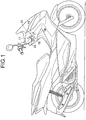
- a cylinder lock 15 that can carry out switching of the switching mode of an ignition switch 14 and switching of steering between a locked state and an unlocked state is disposed in a front part of for example a scooter type two-wheeled motor vehicle.
- a cylinder body 16 of the cylinder lock 15 is disposed so as to be inclined downward to the front, a cylinder lock protective device 17 is mounted on an upper part of the cylinder body 16, and a protective device opening operation restriction device 18 is connectedly provided so as to be adjacent to the cylinder lock protective device 17 from below, the protective device opening operation restriction device 18 having a magnet lock 19 that, when locked, maintains a closed state of the cylinder lock protective device 17.
- the cylinder lock protective device 17 enables a key hole 20 of the cylinder lock 15 to be closed and protected by a shutter plate 36, and the closed state of the cylinder lock protective device 17, that is, a closed position of the shutter plate 36, is maintained by the protective device opening operation restriction device 18 when the magnet lock 19 is locked.
- the magnet lock 19 can be unlocked with a magnet key 22, and due to the magnet lock 19 being unlocked the protective device opening operation restriction device 18 enables an opening operation of the cylinder lock protective device 17, that is, movement of the shutter plate 36 to an open position.
- the magnet key 22 is mounted on a portable case 23 so that it can operate between a projecting position in which it projects from the case 23 (position shown by solid line in FIG. 2 ) and a storage position in which it is stored in the case 23 (position shown by chain line in FIG. 2 ), and a mechanical key 24 for unlocking the cylinder lock 15 is fixed to the case 23 so that it projects toward a direction opposite to the magnet key 22, which is at the projecting position.
- the magnet key 22 is formed by disposing a plurality of, for example three, magnets 26 in a magnet key main body 25, made of a synthetic resin, the magnet key main body 25 being formed lengthwise in the longitudinal direction of the case 23 so that the magnet key main body 25 can be stored in a storage recess portion 28 formed in the case 23 (see FIG. 2 ), one end part of the magnet key main body 25 being pivotably supported on the case 23.
- housing recesses (not illustrated) are disposed along a virtual circle on one face of the other end part of the magnet key main body 25, and in a state in which the magnets 26 are housed in three housing recesses selected from the housing recesses so that either one of the N pole and the S pole faces the outer end of the housing recess, a lid member 27 formed into a ring shape so as to cover all of the housing recesses is glued to the one face of the other end part of the magnet key main body 25, thus forming the magnet key 22.
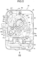
- the cylinder lock protective device 17 includes a casing 35 covering an upper end part of the cylinder body 16 and the shutter plate 36 housed within the casing 35.
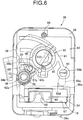
- the casing 35 which has a mechanical key insertion hole 37 (see FIG. 2 ) for the mechanical key 24 to be inserted into the cylinder lock 15, is formed from a body 38 joined to the cylinder body 16, a case 39 secured to the body 38 so as to cover the shutter plate 36 and the body 38 from the side opposite to the cylinder body 16, and an inner cover plate 40 secured to the body 38 so as to be covered with the case 39.
- the mechanical key 24 inserted into the cylinder lock 15 can pivot from a lock (LOCK) position in which the steering is put into a locked state to an on (ON) position via an off (OFF) position, and an engine, which is not illustrated, can be fired up by making the ignition switch 14 conduct at the ON position. Furthermore, the mechanical key 24 can be inserted into or removed from the cylinder lock 15 at either the LOCK position or the OFF position.
- LOCK lock
- OFF off
- a cover sheet 41 is adhered to the surface of the case 39, the cover sheet 41 having an opening 42 corresponding to the mechanical key insertion hole 37, and the cover sheet 41 displaying LOCK, OFF, and ON positions so as to be disposed around the opening 42.
- the shutter plate 36 is housed in the casing 35 so as to be capable of operating between a closed position in which the mechanical key insertion hole 37 is closed and an open position (the position shown in FIG. 5 ) in which the mechanical key insertion hole 37 is open, this shutter plate 36 being disposed between the case 39 and the inner cover plate 40.
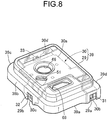
- the case 39 is formed from a case main part 29, made of a resin, and a protector 30, made of a metal, having at least a flat plate portion 30a formed into a flat plate shape so as to cover the shutter plate 36 and being inserted and joined to the case main part 29.
- This case 39 is formed so as to cover the body 38 so that part of the body 38 on the side opposite to the cylinder lock 15 is fitted to the case 39 while having a plurality of side wall portions facing in mutually different directions, and in this embodiment the case 39 is formed into a substantially rectangular bowl shape having four side wall portions 39a, 39b, 39c, and 39d facing in mutually different directions.
- the four side wall portions 39a to 39d of the case 39 at least two side wall portions are resiliently engaged with the body 38, and a side wall portion other than those side wall portions that are resiliently engaged with the body 38 is fastened to the body 38.
- the two side wall portions 39a and 39b are resiliently engaged with the body 38, and another side wall portion 39c is fastened to the body 38.
- the remaining side wall portion 39d may be resiliently engaged with the body 38.
- the protector 30 is formed so as to integrally have, in addition to the flat plate portion 30a, a latching piece 30b, a latching piece 30c, and a mounting piece 30d.
- the latching piece 30b while forming part of the side wall portion 39a of the case 39, is disposed so as to face the outside through a cutout portion 29a formed in the case main part 29 and is connected to the flat plate portion 30a.
- the latching piece 30c while forming part of the side wall portion 39b of the case 39, is disposed so as to face the outside through a cutout portion 29b formed in the case main part 29 and is connected to the flat plate portion 30a.
- the mounting piece 30d while forming part of the side wall portion 39c of the case 39, is disposed so as to face the outside through a cutout portion 29c formed in the case main part 29 and is connected to the flat plate portion 30a.
- the latching pieces 30b and 30c are provided with rectangular latching holes 31 and 32, and a circular insertion hole 33 is provided in the mounting piece 30d.
- engagement projections 38a and 38b are provided integrally with the body 38, the engagement projections 38a and 38b being individually resiliently engaged with the latching holes 31 and 32, and the body 38 is resiliently engaged with the latching pieces 30b and 30c forming part of the side wall portions 39a and 39b.
- the body 38 is provided with a mounting hole 34 corresponding to the insertion hole 33 (see FIG. 4 ); a screw member 43 inserted through the insertion hole 33 is screwed into the mounting hole 34, and the mounting piece 30d forming part of the side wall portion 39c is fastened to the body 38. That is, the protector 30, made of a metal, forming part of the case 39 is mounted on the body 38.
- the inner cover plate 40 is fixed to the body 38 so that the shutter plate 36 is in sliding contact with the inner cover plate 40, and the inner cover plate 40 positioned and engaged with the body 38 at a plurality of locations is secured to the body 38 by means of one screw member 44.
- the mechanical key insertion hole 37 is formed from a circular first hole 45 provided in the inner cover plate 40 and a circular second hole 46 provided in the case 39 so as to correspond to the first hole 45, the shutter plate 36 closing the mechanical key insertion hole 37 by being present between the first hole 45 and the second hole 46.
- the shutter plate 36 is formed so as to integrally have a pivoting base portion 36a formed into a fan shape and having a circular support hole 47 at a position corresponding to the pivot of the fan, a link arm portion 36b extending from the pivoting base portion 36a along the radial direction of the support hole 47, a lid portion 36c connectedly provided on the link arm portion 36b while having a shape that can close the mechanical key insertion hole 37, and a restricting arm portion 36d extending from the lid portion 36c so as to sandwich the mechanical key insertion hole 37 between itself and the pivoting base portion 36a in a state in which the lid portion 36c opens the mechanical key insertion hole 37.
- This shutter plate 36 is pivotably supported by a support shaft 48 inserted into the support hole 47 so that the shutter plate 36 can operate between a closed position in which the mechanical key insertion hole 37 is closed and an open position (the position shown in FIG. 5 ) in which the mechanical key insertion hole 37 is open.
- a latching projection 49 extending in an arc shape with the central axis of the support hole 47 and the support shaft 48 as a center is projectingly provided integrally with a face, on the inner cover plate 40 side, of the pivoting base portion 36a, an operating shaft 50 is projectingly provided integrally with a face, on the case 39 side, of the pivoting base portion 36a, and insertion holes 51 and 52, through which the operating shaft 50 is inserted, are provided in the case 39 and the cover sheet 41 so as to be formed into an arc shape with the central axis of the support hole 47 and the support shaft 48 as a center.
- a latching recess 53 and an inclined face 54 that is inclined so as to go away from the inner cover plate 40 in going from the latching recess 53 toward the extremity of the restricting arm portion 36d.
- closed position restriction means 56 The closed position of the shutter plate 36 is restricted by closed position restriction means 56; this closed position restriction means 56 can switch between a restricted state in which the shutter plate 36 is restricted to the closed position and a restriction release state in which operation of the shutter plate 36 to the open position is allowed, and includes first and second restricting members 57 and 58.
- the first restricting member 57 is formed so as to have a flat-shaped pivoting plate portion 57a disposed between the body 38 and the inner cover plate 40, the support shaft 48, which is standingly provided on the pivoting plate portion 57a so as to extend through a first through hole 59 provided in the inner cover plate 40 and be inserted into the support hole 47 of the shutter plate 36, a first engagement projection portion 57b standingly provided on the pivoting plate portion 57a so as to abut against and engage with one peripheral end portion 49a of the latching projection 49 of the shutter plate 36, a cylindrical portion 57c connectedly provided on the pivoting plate portion 57a at right angles so as to be coaxial with the support shaft 48 and pivotably inserted into the body 38, and a first pressure-receiving projecting portion 57d projecting radially outward from an intermediate part in the axial direction of the cylindrical portion 57c.
- the inner cover plate 40 is provided with an elongated hole 60 through which the first engagement projection portion 57b is inserted so that the first engagement projection portion 57b can pivot around the central axis of the support shaft 48, the elongated hole 60 extending in an arc shape with the central axis of the support shaft 48 as a center.
- the second restricting member 58 is formed so as to have a flat-shaped linking plate portion 58a disposed between the body 38 and the inner cover plate 40, a second engagement projection portion 58b projectingly provided on one end part of the linking plate portion 58a so as to extend through a second through hole 61 provided in the inner cover plate 40 while being capable of engaging with the latching recess 53, a rod-shaped portion 58c inserted into the body 38 via the other end part of the linking plate portion 58a so as to extend in parallel to the support shaft 48, and a second pressure-receiving projecting portion 58d projecting radially outward from the rod-shaped portion 58c.
- the shutter plate 36 is urged toward the open position side by means of a first torsion spring 62; the first torsion spring 62 is disposed between the pivoting base portion 36a of the shutter plate 36 and the inner cover plate 40 so as to surround the support shaft 48, one end portion 62a of the first torsion spring 62 is engaged with the inner cover plate 40, and the other end portion 62b of the first torsion spring 62 abuts against and engages with the other peripheral end portion 49b of the latching projection 49 of the shutter plate 36.
- an urging force toward the closed position side can be exerted on the shutter plate 36 by means of a coil-shaped second torsion spring 63 that exhibits an urging force larger than that of the first torsion spring 62.
- This second torsion spring 63 is provided between the cylindrical portion 57c and the body 38 while having part thereof inserted into the cylindrical portion 57c; one end portion 63a of the second torsion spring 63 is engaged with the body 38, and the other end portion of the second torsion spring 63 is engaged with a groove (not illustrated) formed in an inner face of the cylindrical portion 57c so as to extend in the axial direction.
- the second torsion spring 63 exhibits a spring force that urges the shutter plate 36 toward the closed position side together with the first restricting member 57 as well as an axial spring force that urges the first restricting member 57 in a direction in which the pivoting plate portion 57a of the first restricting member 57 moves toward the inner cover plate 40.
- a first coil spring 64 is provided in a compressed state between the body 38 and the rod-shaped portion 58c of the second restricting member 58; the second restricting member 58 is urged toward the side on which the second engagement projection portion 58b projects from the inner cover plate 40 by means of the spring force exhibited by the first coil spring 64, and the shutter plate 36 is also restricted to the closed position by the second engagement projection portion 58b engaging with the latching recess 53 of the shutter plate 36.
- a state in which the shutter plate 36 is restricted to the closed position by the closed position restriction means 56 can be released by the protective device opening operation restriction device 18;
- this protective device opening operation restriction device 18 includes the magnet lock 19 that can be unlocked by the magnet key 22 and is arranged so as to release the restricted state of the closed position restriction means 56 by operation in response to pushing in the magnet key 22 in an unlocked state of the magnet lock 19.
- the protective device opening operation restriction device 18 shares the casing 35 with the cylinder lock protective device 17, and the body 38 of the casing 35 is provided with a slide recess 67 opening on the case 39 side in a section that is offset from the inner cover plate 40 while having a substantially rectangular box-shaped cross-sectional shape and extending in parallel to the central axis of the support shaft 48. Furthermore, a magnet key insertion hole 69 having a shape corresponding to the cross-sectional shape of the magnet key 22 is provided in a portion, corresponding to the slide recess 67, of the case 39. Moreover, as shown in FIG. 4 , a lid member 70 for closing the magnet key insertion hole 69 is pivotably supported on a reverse face of the case 39 via a pin 71, and the lid member 70 is urged toward the closed side by a spring 72.
- the magnet lock 19 is disposed on the casing 35 so as to face the slide recess 67 and includes a rotor 74 pivotably supported on the body 38.
- the rotor 74 is formed from a non-magnetic material so as to integrally have a disk-shaped portion 74a, a collar portion 74b protruding radially outward from one end of the disk-shaped portion 74a, a link arm portion 74c extending outward from one location in the peripheral direction of the collar portion 74b, and a third engagement projection portion 74d projecting toward the same side as the disk-shaped portion 74a from the outer end of the link arm portion 74c.
- a fitting recess 75 As shown in FIG. 16 , provided in the body 38 of the casing 35 are a fitting recess 75, a circular fitting hole 76, and an elongated hole 77, the fitting recess 75 having the collar portion 74b and the link arm portion 74c of the rotor 74 pivotably fitted thereinto, the fitting hole 76 having the disk-shaped portion 74a of the rotor 74 pivotably fitted thereinto while having its outer end opening in the fitting recess 75 and having its inner end opening on a side face of the slide recess 67, and the elongated hole 77 having its outer end opening in the fitting recess 75 so that the third engagement projection portion 74d is inserted thereinto and having its inner end opening on the side face of the slide recess 67.
- the elongated hole 77 is formed into an arc shape with the pivot axis of the rotor 74 as a center so as to allow pivoting of the rotor 74 within the fitting rece
- the fitting recess 75 is closed by means of a lid member 78 that integrally has a supporting projecting portion 78a fitted into the disk-shaped portion 74a of the rotor 74 and supporting pivoting of the rotor 74, and that is secured to the body 38 by means of one screw member 79, an O ring 80 being disposed between a base part of the supporting projecting portion 78a and the rotor 74.
- a plurality of, for example three, pins 81 which are magnets, are slidably fitted into the extremity of the supporting projecting portion 78a so as to be capable of moving between a position in which they engage with three of four latching recesses 82 provided in one end of the disk-shaped portion 74a of the rotor 74 and a position in which engagement is released, each pin 81 being resiliently urged toward the side on which it engages with the rotor 74 by means of second coil springs 83 individually corresponding thereto.
- the three pins 81 are fitted into the latching recesses 82 so as to be disposed at positions corresponding to the three magnets 31 of the magnet key 22 when the magnet key 22 opposes the other end of the disk-shaped portion 74a of the rotor 74.
- the pins 81 are disposed so that the same pole as the pole, on the magnet lock 19 side, of the magnet 26 of the magnet key 22 is disposed on the inner end side of the latching recess 82, and when a legitimate magnet key 22 is disposed at a position opposing the other end of the disk-shaped portion 74a of the rotor 74 the pin 81 can move to the side that releases engagement with the rotor 74 against the resilient urging force of the second coil spring 83, thereby allowing pivoting of the rotor 74.
- a magnet key follower member 84 is slidably housed in the slide recess 67 of the body 38 of the casing 35, the magnet key follower member 84 moving together with the magnet key 22 in response to the magnet key 22 being inserted into the casing 35.
- the magnet key follower member 84 is formed into a rectangular box shape so as to have a magnet key insertion recess 85 and be slidably housed in the slide recess 67, the magnet key 22 opening the lid member 70 and being inserted into the magnet key insertion recess 85 of the magnet key follower member 84 through the magnet key insertion hole 69 of the case 39.
- a lattice-shaped receiving part 68 is provided integrally with the body 38, the lattice-shaped receiving part 68 being disposed on an end part of the slide recess 67 on the side opposite to the case 39, and a third coil spring 86 is provided in a compressed state between the magnet key follower member 84 and the receiving part 68, the magnet key follower member 84 being spring-biased to the side on which it is moved toward the case 39 by means of the spring force exhibited by the third coil spring 86.
- a window 87 is formed in a side wall, looking out on the magnet lock 19 side, of the magnet key follower member 84 lengthwise along the extending direction of the slide recess 67, the magnet key 22 inserted into the magnet key insertion recess 85 looking out on the magnet lock 19 side via the window 87.
- the magnet key follower member 84 moves together with the magnet key 22 in response to insertion of the magnet key 22 so as to make the magnet key 22 oppose the blocked end outer face of the rotor 74 of the magnet lock 19, thus not only enabling the magnet key 22 to be inserted into an unlocked position in which the magnet lock 19 is unlocked but also enabling the magnet key 22 to be pushed in further from the unlocked position to thus move to a pushed-in position.
- a restriction release member 88 that engages with the third engagement projection portion 74d of the rotor 74, movement of the restriction release member 88 being restricted by the rotor 74 in a state in which the magnet lock 19 is locked.
- a fourth coil spring 89 Provided between the magnet key follower member 84 and the restriction release member 88 is a fourth coil spring 89 exhibiting a resilient force that pushes the restriction release member 88 toward the side that pivots the rotor 74 in response to movement of the magnet key follower member 84 toward the pushed-in position side.
- the restriction release member 88 has a substantially C-shaped form opening toward the link arm portion 74c of the rotor 74 while having a latching groove 90 with which the third engagement arm portion 74d engages.
- a housing hole 91 opening on the second restricting member 58 side and on the third engagement arm portion 74d side of the rotor 74 while having opposite ends in the extending direction of the slide recess 67 blocked.
- the restriction release member 88 is housed within the housing hole 91, and the fourth coil spring 89 housed within the housing hole 91 is provided in a compressed state between the magnet key follower member 84 and the restriction release member 88.
- a first pressing projecting portion 84a is projectingly provided on the magnet key follower member 84, the first pressing projecting portion 84a being capable of engaging, from the pivoting base portion 36a side, with the first pressure-receiving projecting portion 57d provided on the cylindrical portion 57c of the first restricting member 57.
- the restriction release member 88 is provided with a second pressing projecting portion 88a so as to project from the restriction release member 88 on the side opposite to the latching groove 90, the second pressing projecting portion 88a being capable of engaging, from the linking plate portion 58a side, with the second pressure-receiving projecting portion 58d provided on the rod-shaped portion 58c of the second restricting member 58.
- the magnet key follower member 84 is forcibly pushed in using a different type of key or an unauthorized member without the magnet lock 19 being unlocked, although restriction of the shutter plate 36 to the closed position by the first restricting member 57 is released in response to movement of the magnet key follower member 84, since the rotor 74 of the magnet lock 19 will not pivot and movement of the restriction release member 88 is prevented, the magnet key follower member 84 slides while compressing the fourth coil spring 89, restriction of the shutter plate 36 at the closed position by the second restricting member 58 will not be released, and the shutter plate 36 remains restricted to the closed position.
- the protective device opening operation restriction device 18 is formed from the magnet lock 19, the magnet key follower member 84, the restriction release member 88, and the third and fourth coil springs 86 and 89.
- the magnet key follower member 84 is provided with a first discharge hole 92 via which a lower part of the magnet key insertion recess 85 communicates with the outside, and an inclined face 92a is formed on an open end of the first discharge hole 92 that is open to the magnet key insertion recess 85, the inclined face 92a being for smoothly discharging dirt, rainwater, etc. that has entered the magnet key insertion recess 85.
- the body 38 of the casing 35 is provided with a second discharge hole 93 via which a lower part of the slide recess 67 communicates with the outside in order to drain dirt or water that has entered the slide recess 67, this second discharge hole 93 being formed by the lattice-shaped receiving part 68.
- the second discharge hole 93 is provided in the body 38 of the casing 35 so as to communicate with at least part of the first discharge hole 92 when the magnet key follower member 84 reaches the pushed-in position.
- the latching projection 49 of the shutter plate 36 reaches a position where it moves toward and opposes, in a direction along the axis of the support shaft 48, the first engagement projection portion 57b of the first restricting member 57, and even when the pressing force acting on the first pressure-receiving projecting portion 57d from the first pressing projecting portion 84a is released due to the magnet key follower member 84 being returned to the original position by means of the spring force of the third coil spring 86 by pulling the magnet key 22 out of the magnet key follower member 84, the first engagement projection portion 57b abuts against the latching projection 49 of the shutter plate 36 in the axial direction, and the first restricting member 57 remains pushed down. Furthermore, the second restricting member 58 is returned to its original position, due to release of the pressing force acting on the second pressure-receiving projecting portion 58d from the second
- closed position side urging force control means 94 stops the function of the first torsion spring 62 at least when the shutter plate 36 operates from the closed position to the open position and makes the urging force of the second torsion spring 63 act on the shutter plate 36 in response to pulling out of the mechanical key 24 at a predetermined pivoting position from the mechanical key insertion hole 37 in a state in which the shutter plate 36 is at the open position.
- the closed position side urging force control means 94 includes a disk-shaped cam plate 95 pivotably housed between the body 38 and the inner cover plate 40, a lever member 96 disposed outside the cam plate 95 so as to be disposed between the first and second restricting members 57 and 58 in the peripheral direction of the cam plate 95, a push plate 97 fitted into the cam plate 95 so that it can slide in the radial direction of the cam plate 95, a follower 98 abutting against the push plate 97 when the cam plate 95 is at a pivoting position that corresponds to the LOCK position, and a slide member 99 linked to the follower 98.
- the cam plate 95 is relatively non-pivotably linked to an inner cylinder (not illustrated) of the cylinder lock 15 and is formed so as to integrally have a disk portion 95a and a collar portion 95b protruding in the radially outward direction from an end part, on the body 38 side, of the disk portion 95a. Moreover, the pivoting plate portion 57a of the first restricting member 57 is disposed between the collar portion 95b and the inner cover plate 40.
- the lever member 96 is pivotably supported on the body 38 by means of a pin 100 parallel to the support shaft 48 such that one end portion 96a can abut against the outer periphery of the collar portion 95b of the cam plate 95 and the other end portion 96b abuts against the pivoting plate portion 57a of the first restricting member 57, the pin 100 being formed integrally with the lever member 96.
- a recess 101 Formed in the outer periphery of the collar portion 95b is a recess 101 housing the one end part 96a of the lever member 96 when the cam plate 95 is at a pivoting position corresponding to the LOCK position.
- the one end portion 96a of the lever member 96 is disengaged from the recess 101 and pivoted so as to be in sliding contact with the outer periphery of the collar portion 95b.
- the other end portion 96b of the lever member 96 is made to abut against the pivoting plate portion 57a of the first restricting member 57 so as to oppose the pivoting direction of the first restricting member 57 by means of the urging force of the second torsion spring 63.
- a rectangular through hole 102 corresponding to the mechanical key insertion hole 37 is formed in a center part of the cam plate 95 so as to have a rectangular cross-sectional shape, and a fitting groove 103 having its inner end opening in the through hole 102 and its outer end opening on the outer periphery of the disk portion 95a is provided so as to extend in the radial direction of the cam plate 95.
- the push plate 97 is slidably fitted into the fitting groove 103, and a pair of springs 104 are provided between the cam plate 95 and the push plate 97 so as to urge the push plate 97 toward the side on which it closes the through hole 102, that is, in the radially inward direction of the cam plate 95.
- An inner end part of the push plate 97 is formed so that it can block the through hole 102, and an outer end part of the push plate 97 is formed into an arc shape having the same curvature as that of the outer periphery of the disk portion 95a of the cam plate 95.
- the outer end part of the push plate 97 is present at a position further inward than the outer periphery of the disk portion 95a, and when the inner end part of the push plate 97 is at a position where the through hole 102 is opened, the outer end part of the push plate 97 is at a position where it is flush with the outer periphery of the disk portion 95a.
- the follower 98 is disposed on the side opposite to the second restricting member 58 with respect to the cam plate 95, and integrally has a follower main portion 98b extending along the outer periphery of the cam plate 95 while having a link pin 98a in one end part and being capable of having part thereof superimposed on the collar portion 95b of the cam plate 95, a fitting portion 98c extending from the other end part of the follower main portion 98b toward the disk portion 95a of the cam plate 95, and a short columnar portion 98d linked to the other end part of the follower main portion 98b so as to be disposed on the outside of the collar portion 95b.
- a spring latching recess 105 is formed in a side face, on the side opposite to the fitting portion 98c, of the follower main portion 98b.
- the extremity of the fitting portion 98c can abut against the outer periphery of the disk portion 95a of the cam plate 95, and when the cam plate 95 is at the LOCK position, the extremity of the fitting portion 98c abuts against the outer end part of the push plate 97.
- a third torsion spring 107 surrounds a supporting projection 106 provided on the body 38 and having a circular cross section, and has one end portion 107a engaged with the body 38 and the other end portion 107b abutting against and engaging with the short columnar portion 98d on the other end part of the follower 98 so that part of the other end portion 107b can be housed in the spring latching recess 105.
- the spring force exhibited by the third torsion spring 107 acts on the follower 98 in a direction in which the fitting portion 98c of the follower 98 is pushed against the outer periphery of the disk portion 95a of the cam plate 95 and a direction in which the follower 98 is pushed toward the first restricting member 57 side.
- the body 38 In order to guide movement of the follower 98 accompanying movement of the push plate 97 and pivoting of the cam plate 95, the body 38 has a guide recess 109 formed therein, the extremity of the short columnar portion 98d of the follower 98 being fitted into the guide recess 109.
- the slide member 99 is disposed between the follower 98 and the first restricting member 57 and supported on the body 38 so that it can slide in a direction in which it moves toward and away from the first restricting member 57, and a bottomed fitting hole 108 into which the link pin 98a of the follower 98 is pivotably fitted is provided in the slide member 99.
- An abutment portion 99a is provided integrally with an end part, on the first restricting member 57 side, of the slide member 99 so that it can overlap the collar portion 95b of the cam plate 95 in the axial direction, the abutment portion 99a being capable of being made to abut against the pivoting plate portion 57a of the first restricting member 57 from the same direction as the pivotingly urging direction of the first restricting member 57 by means of the second torsion spring 63.
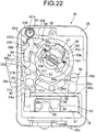
- the lever member 96 pivots to a position in which the one end portion 96a is disengaged from the recess 101 of the collar portion 95b of the cam plate 95 and is in sliding contact with the outer periphery of the collar portion 95b, and the other end portion 96b of the lever member 96 pivots the pivoting plate portion 57a of the first restricting member 57 in the counterclockwise direction in FIG. 22 .
- the first restricting member 57 is thereby pivoted to a position where the first engagement projection portion 57b abuts against and engages with the one peripheral end portion 49a of the latching projection 49 of the shutter plate 36 and where the first pressure-receiving projecting portion 57d is displaced from the first pressing projecting portion 84a of the magnet key follower member 84 in the peripheral direction of the support shaft 48; in response to release of a state in which the first engagement projection portion 57b abuts against the latching projection 49 of the shutter plate 36 at the LOCK position, as shown in FIG.
- the first restricting member 57 moves in a direction in which the pivoting plate portion 57a is made to move toward the shutter plate 36 by means of the axial resilient force of the second torsion spring 63, and the first engagement projection portion 57b is made to move toward and oppose the one peripheral end portion 49a of the first latching projection 49 in the peripheral direction of the support shaft 48 and, furthermore, abut against and engage with the one peripheral end portion of the first latching projection 49 by means of the spring force of the second torsion spring 63.
- the pivoting plate portion 57a pivots so that part thereof passes between the abutment portion 99a at the extremity of the slide member 99 and the collar portion 95b of the cam plate 95, the first restricting member 57 is moved by means of the axial resilient force of the second torsion spring 63 in a direction in which the pivoting plate portion 57a moves toward the shutter plate 36, as shown in FIG. 22 the abutment portion 99a is thereby made to abut against the pivoting plate portion 57a so as to oppose the pivotingly urging direction of the first restricting member 57 by means of the spring force of the second torsion spring 63, and the first restricting member 57 is therefore prevented from pivoting.
- the other end portion 96b of the lever member 96 remains abutting against the pivoting plate portion 57a of the first restricting member 57, and since the one end portion 96a of the lever member 96 abuts against the outer periphery of the collar portion 95b of the cam plate 95, pivoting of the first restricting member 57 is also prevented by the lever member 96.
- the closed position side urging force control means 94 stops the function of the first torsion spring 62 when the shutter plate 36 operates from the closed position to the open position, and makes the urging force of the first torsion spring 62 act on the shutter plate 36 in response to pulling the mechanical key 24 at the LOCK position out of the mechanical key insertion hole 37 in a state in which the shutter plate 36 is at the open position.
- the mechanical key 24 at the OFF position could be pulled out of the mechanical key insertion hole 37, and in this case since the closed position side urging force control means 94 does not make the urging force of the second torsion spring 63 act on the shutter plate 36, at the OFF position the shutter plate 36 does not automatically pivot to the closed position side.
- Pivoting the part of the operating shaft 50 projecting from the casing 35 enables the shutter plate 36 to be pivoted to the closed position, but in this process since the first restricting member 57 is in a state in which pivoting is prevented by means of the slide member 99 and the lever member 96, the shutter plate 36 pivots while leaving behind the first restricting member 57, and the closed position of the shutter plate 36 is restricted by the second engagement projection portion 58b of the second restricting member 58 engaging with the latching recess 53.
- the magnet key 22 when opening the shutter plate 36, the magnet key 22 may be inserted into the magnet key follower member 84 and pushed down, and due to the second restricting member 58 being pushed down the second engagement projection portion 58b is disengaged from the latching recess 53, restriction of the closed position of the shutter plate 36 by means of the second restricting member 58 is released, and since the spring force of the second torsion spring 63 is not acting on the shutter plate 36, the shutter plate 36 is automatically pivoted to the open position by means of the spring force of the first torsion spring 62.
- the protective device opening operation restriction device 18, which has the magnet lock 19 that, when locked, maintains the closed state of the cylinder lock protective device 17 and allows an opening operation by the cylinder lock protective device 17 in response to the magnet lock 19 being unlocked by means of the magnet key 22, includes the casing 35 that has the slide recess 67 and has the magnet lock 19 disposed so as to face the slide recess 67, the magnet key follower member 84 that, while having the magnet key insertion recess into which the magnet key 22 can be inserted, is slidably fitted into the slide recess 67 and not only enables movement to the unlocked position in which the magnet lock 19 is unlocked by pushing in the magnet key 22 but also enables movement to a pushed-in position by pushing in the magnet key 22 further from the unlocked position, and the restriction release member 88 that operates in response to movement of the magnet key follower member 84 from the unlocked position to the pushed-in position and enables an opening operation by the cylinder lock protective device 17, it is
- the magnet key follower member 84 is provided with the first discharge hole 92, via which the lower part of the magnet key insertion recess 85 communicates with the outside, and the casing 35 is provided with the second discharge hole 93, via which the lower part of the slide recess 67 communicates with the outside, even if dirt, rainwater, etc. enters the slide recess 67 of the casing 35 and the magnet key insertion recess 85 of the magnet key follower member 84 from the outside, the dirt, rainwater, etc. can be discharged to the outside, thus enabling any harmful effect due to dirt, rainwater, etc. entering the casing 35 and the magnet key follower member 84 from the outside and accumulating to be eliminated.
- the second discharge hole 93 is provided in the casing 35 so as to communicate with at least part of the first discharge hole 92 when the magnet key follower member 84 reaches the pushed-in position, it is possible to reliably discharge dirt, rainwater, etc.
- the casing 35 of the cylinder lock protective device 17 includes the body 38 provided so as to be connected to the cylinder body 16 of the cylinder lock 15 and the case 39 formed so as to cover the shutter plate 36 and be fixed to the body 38, and the case 39 is formed from the case main part 29, made of a resin, and the protector 30, made of a metal, having at least the flat plate portion 30a formed into a flat plate shape so as to cover the shutter plate 36, and being inserted and joined to the case main part 29, due to the case main part 29 being made of a resin the weight of the case 39 can be lightened, and due to the protector 30 made of a metal forming the case together with the case main part 29 and being inserted and joined to the case main part 29, the theft resistance can be ensured.
- the protector 30 is fixed to the body 38, fixing of the case 39 to the body 38 can be made strong.
- case 39 is formed so as to have the plurality of side wall portions 39a, 39b, 39c, and 39d disposed so as to face mutually different directions, including at least two side wall portions 39a and 39b resiliently engaged with the body 38 and, in addition to the side wall portions 39a and 39b, one side wall portion 39c fastened to the body 38, it is possible to make assembly of the case 39 to the body 38 easy, thus enhancing the ease of assembly.
Abstract
Description
- The present invention relates to a protective device for a cylinder lock in which a shutter plate is supported on a casing having a mechanical key insertion hole for a mechanical key to be inserted into a cylinder lock, the shutter plate being covered by a case forming part of the casing and being capable of moving between a closed position in which the shutter plate closes the mechanical key insertion hole and an open position in which the mechanical key insertion hole is opened.
- A protective device for a cylinder lock that includes a shutter plate that opens and closes a key hole of the cylinder lock is known from Patent Document 1.
- Patent Document 1: Japanese Patent No.
3914043 - In the arrangement disclosed in Patent Document 1 above, a case forming part of a casing and covering the shutter plate is formed from a metal such as zinc in order to ensure theft resistance, thus causing the casing to increase in weight and thereby resulting in an increase in weight of a vehicle, etc. on which the cylinder lock is disposed.
- The present invention has been accomplished in light of such circumstances, and it is an object thereof to provide a protective device for a cylinder lock that can lighten the weight of a case forming part of a casing while ensuring the theft resistance.
- In order to attain the above object, according to a first aspect of the present invention, there is provided a protective device for a cylinder lock in which a shutter plate is supported on a casing having a mechanical key insertion hole for a mechanical key to be inserted into a cylinder lock, the shutter plate being covered by a case forming part of the casing and being capable of moving between a closed position in which the shutter plate closes the mechanical key insertion hole and an open position in which the mechanical key insertion hole is opened, characterized in that the casing comprises a body that is provided so as to be connected to a cylinder body of the cylinder lock, and the case, which is formed so as to cover the shutter plate and is fixed to the body, and the case comprises a case main part, made of a resin, and a protector, made of a metal, that has at least a flat plate portion formed into a flat plate shape so as to cover the shutter plate and that is inserted and joined to the case main part.
- Further, according to a second aspect of the present invention, in addition to the first aspect, the protector is fixed to the body.
- Furthermore, according to a third aspect of the present invention, in addition to the first or second aspect, the case is formed so as to comprise a plurality of side wall portions disposed so as to face mutually different directions, at least two side wall portions being resiliently engaged with the body, and other than these side wall portions one side wall portion being fastened to the body.
- In accordance with the first aspect of the present invention, due to the case main part being made of a resin, the weight of the case can be lightened, and due to the protector, made of a metal, forming the case together with the case main part being inserted and joined to the case main part it is possible to ensure the theft resistance.
- Furthermore, in accordance with the second aspect of the present invention, since the protector is fixed to the body, fixing of the case to the body can be made strong.
- Moreover, in accordance with the third aspect of the present invention, the case has a plurality of side wall portions disposed so as to face mutually different directions, and since among the side wall portions, at least two side wall portions are resiliently engaged with the body, and another one of the side wall portions is fastened to the body, it is possible to make assembly of the case to the body easy, thus enhancing the ease of assembly.
-
- [
FIG. 1] FIG. 1 is a side view of a two-wheeled motor vehicle. (first embodiment) - [
FIG. 2] FIG. 2 is a perspective view of a cylinder lock, a cylinder lock protective device, a protective device opening operation restriction device, and a key unit. (first embodiment) - [
FIG. 3] FIG. 3 is a perspective view of a magnet key. (first embodiment) - [
FIG. 4] FIG. 4 is an exploded perspective view of the cylinder lock protective device and the protective device opening operation restriction device. (first embodiment) - [
FIG. 5] FIG. 5 is a front view of the cylinder lock protective device and the protective device opening operation restriction device showing a state in which a shutter plate is at an open position and a case is omitted. (first embodiment) - [
FIG. 6] FIG. 6 is a front view in a state in which the shutter plate is removed fromFIG. 5 . (first embodiment) - [
FIG. 7] FIG. 7 is a front view in a state in which an inner cover plate is removed fromFIG. 6 . (first embodiment) - [
FIG. 8] FIG. 8 is a perspective view of the case. (first embodiment) - [
FIG. 9] FIG. 9 is a perspective view of a protector. (first embodiment) - [
FIG. 10] FIG. 10 is a perspective view of a casing. (first embodiment) - [
FIG. 11] FIG. 11 is a perspective view of the shutter plate when viewed from the side opposite to the case. (first embodiment) - [
FIG. 12] FIG. 12 is a front view of the cylinder lock protective device and the protective device opening operation restriction device showing a state in which the shutter plate is at a closed position and the case is omitted. (first embodiment) - [
FIG. 13] FIG. 13 is a perspective view of the cylinder lock protective device and the protective device opening operation restriction device showing a state in which the shutter plate is at the closed position and the casing is omitted. (first embodiment) - [
FIG. 14] FIG. 14 is a view in the direction ofarrow 14 inFig. 13 . (first embodiment) - [
FIG. 15] FIG. 15 is a perspective view showing an arrangement in which a magnet lock, a restriction release member, and a second restricting member are linked. (first embodiment) - [
FIG. 16] FIG. 16 is a side view when a body of the casing is viewed from the direction ofarrow 16 inFIG. 5 . (first embodiment) - [
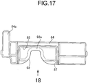
FIG. 17] FIG. 17 is a front view of a magnet key follower member. (first embodiment) - [
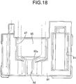
FIG. 18] FIG. 18 is a view in the direction ofarrow 18 inFig. 17 . (first embodiment) - [
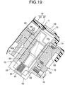
FIG. 19] FIG. 19 is a sectional view along line 19-19 inFIG. 2 . (first embodiment) - [
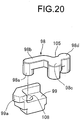
FIG. 20] FIG. 20 is an exploded perspective view of a follower and a slide member. (first embodiment) - [
FIG. 21] FIG. 21 is a front view, corresponding toFIG. 12 , in a state in which a mechanical key is inserted at a LOCK position. (first embodiment) - [
FIG. 22] FIG. 22 is a front view, corresponding toFIG. 12 , in a state in which the mechanical key is pivoted to an OFF position. (first embodiment) - [
FIG. 23] FIG. 23 is a view, corresponding toFIG. 14 , in a state in which the casing is omitted. (first embodiment) - [
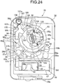
FIG. 24] FIG. 24 is a front view, corresponding toFIG. 12 , in a state in which the mechanical key is pivoted to an ON position. (first embodiment) - [
FIG. 25] FIG. 25 is a front view, corresponding toFIG. 12 , in a state in which the mechanical key is pulled out at the LOCK position. (first embodiment) -
- 15
- Cylinder lock
- 16
- Cylinder body
- 17
- Cylinder lock protective device
- 24
- Mechanical key
- 29
- Case main part
- 30
- Protector
- 30a
- Flat plate portion
- 35
- Casing
- 36
- Shutter plate
- 37
- Mechanical key insertion hole
- 38
- Body
- 39
- Case
- 39a, 39b, 39c, 39d
- Side wall portion
- An embodiment of the present invention is explained below by reference to the attached
FIG. 1 to FIG. 25 . - First, in
FIG. 1 , acylinder lock 15 that can carry out switching of the switching mode of anignition switch 14 and switching of steering between a locked state and an unlocked state is disposed in a front part of for example a scooter type two-wheeled motor vehicle. Acylinder body 16 of thecylinder lock 15 is disposed so as to be inclined downward to the front, a cylinder lockprotective device 17 is mounted on an upper part of thecylinder body 16, and a protective device openingoperation restriction device 18 is connectedly provided so as to be adjacent to the cylinder lockprotective device 17 from below, the protective device openingoperation restriction device 18 having amagnet lock 19 that, when locked, maintains a closed state of the cylinder lockprotective device 17. - In
FIG. 2 , the cylinder lockprotective device 17 enables akey hole 20 of thecylinder lock 15 to be closed and protected by ashutter plate 36, and the closed state of the cylinder lockprotective device 17, that is, a closed position of theshutter plate 36, is maintained by the protective device openingoperation restriction device 18 when themagnet lock 19 is locked. Themagnet lock 19 can be unlocked with amagnet key 22, and due to themagnet lock 19 being unlocked the protective device openingoperation restriction device 18 enables an opening operation of the cylinder lockprotective device 17, that is, movement of theshutter plate 36 to an open position. - The
magnet key 22 is mounted on aportable case 23 so that it can operate between a projecting position in which it projects from the case 23 (position shown by solid line inFIG. 2 ) and a storage position in which it is stored in the case 23 (position shown by chain line inFIG. 2 ), and amechanical key 24 for unlocking thecylinder lock 15 is fixed to thecase 23 so that it projects toward a direction opposite to themagnet key 22, which is at the projecting position. - In
FIG. 3 , themagnet key 22 is formed by disposing a plurality of, for example three,magnets 26 in a magnet keymain body 25, made of a synthetic resin, the magnet keymain body 25 being formed lengthwise in the longitudinal direction of thecase 23 so that the magnet keymain body 25 can be stored in astorage recess portion 28 formed in the case 23 (seeFIG. 2 ), one end part of the magnet keymain body 25 being pivotably supported on thecase 23. - Four housing recesses (not illustrated) are disposed along a virtual circle on one face of the other end part of the magnet key
main body 25, and in a state in which themagnets 26 are housed in three housing recesses selected from the housing recesses so that either one of the N pole and the S pole faces the outer end of the housing recess, alid member 27 formed into a ring shape so as to cover all of the housing recesses is glued to the one face of the other end part of the magnet keymain body 25, thus forming themagnet key 22. - Referring in addition to
FIG. 4 to FIG. 7 , the cylinder lockprotective device 17 includes acasing 35 covering an upper end part of thecylinder body 16 and theshutter plate 36 housed within thecasing 35. - The
casing 35, which has a mechanical key insertion hole 37 (seeFIG. 2 ) for the mechanical key 24 to be inserted into thecylinder lock 15, is formed from abody 38 joined to thecylinder body 16, acase 39 secured to thebody 38 so as to cover theshutter plate 36 and thebody 38 from the side opposite to thecylinder body 16, and aninner cover plate 40 secured to thebody 38 so as to be covered with thecase 39. - The mechanical key 24 inserted into the
cylinder lock 15 can pivot from a lock (LOCK) position in which the steering is put into a locked state to an on (ON) position via an off (OFF) position, and an engine, which is not illustrated, can be fired up by making theignition switch 14 conduct at the ON position. Furthermore, the mechanical key 24 can be inserted into or removed from thecylinder lock 15 at either the LOCK position or the OFF position. - A
cover sheet 41 is adhered to the surface of thecase 39, thecover sheet 41 having anopening 42 corresponding to the mechanicalkey insertion hole 37, and thecover sheet 41 displaying LOCK, OFF, and ON positions so as to be disposed around theopening 42. - The
shutter plate 36 is housed in thecasing 35 so as to be capable of operating between a closed position in which the mechanicalkey insertion hole 37 is closed and an open position (the position shown inFIG. 5 ) in which the mechanicalkey insertion hole 37 is open, thisshutter plate 36 being disposed between thecase 39 and theinner cover plate 40. - In
FIG. 8 , thecase 39 is formed from a casemain part 29, made of a resin, and aprotector 30, made of a metal, having at least aflat plate portion 30a formed into a flat plate shape so as to cover theshutter plate 36 and being inserted and joined to the casemain part 29. Thiscase 39 is formed so as to cover thebody 38 so that part of thebody 38 on the side opposite to thecylinder lock 15 is fitted to thecase 39 while having a plurality of side wall portions facing in mutually different directions, and in this embodiment thecase 39 is formed into a substantially rectangular bowl shape having fourside wall portions - Moreover, among the four
side wall portions 39a to 39d of thecase 39, at least two side wall portions are resiliently engaged with thebody 38, and a side wall portion other than those side wall portions that are resiliently engaged with thebody 38 is fastened to thebody 38. In this embodiment the twoside wall portions body 38, and anotherside wall portion 39c is fastened to thebody 38. The remainingside wall portion 39d may be resiliently engaged with thebody 38. - Referring in addition to
FIG. 9 , theprotector 30 is formed so as to integrally have, in addition to theflat plate portion 30a, alatching piece 30b, a latchingpiece 30c, and a mountingpiece 30d. The latchingpiece 30b, while forming part of theside wall portion 39a of thecase 39, is disposed so as to face the outside through acutout portion 29a formed in the casemain part 29 and is connected to theflat plate portion 30a. The latchingpiece 30c, while forming part of theside wall portion 39b of thecase 39, is disposed so as to face the outside through acutout portion 29b formed in the casemain part 29 and is connected to theflat plate portion 30a. The mountingpiece 30d, while forming part of theside wall portion 39c of thecase 39, is disposed so as to face the outside through acutout portion 29c formed in the casemain part 29 and is connected to theflat plate portion 30a. The latchingpieces circular insertion hole 33 is provided in the mountingpiece 30d. - Referring in addition to
FIG. 10 ,engagement projections body 38, theengagement projections body 38 is resiliently engaged with the latchingpieces side wall portions body 38 is provided with a mountinghole 34 corresponding to the insertion hole 33 (seeFIG. 4 ); ascrew member 43 inserted through theinsertion hole 33 is screwed into the mountinghole 34, and the mountingpiece 30d forming part of theside wall portion 39c is fastened to thebody 38. That is, theprotector 30, made of a metal, forming part of thecase 39 is mounted on thebody 38. - The
inner cover plate 40 is fixed to thebody 38 so that theshutter plate 36 is in sliding contact with theinner cover plate 40, and theinner cover plate 40 positioned and engaged with thebody 38 at a plurality of locations is secured to thebody 38 by means of onescrew member 44. - The mechanical
key insertion hole 37 is formed from a circularfirst hole 45 provided in theinner cover plate 40 and a circularsecond hole 46 provided in thecase 39 so as to correspond to thefirst hole 45, theshutter plate 36 closing the mechanicalkey insertion hole 37 by being present between thefirst hole 45 and thesecond hole 46. - Referring in addition to
FIG. 11 , theshutter plate 36 is formed so as to integrally have apivoting base portion 36a formed into a fan shape and having acircular support hole 47 at a position corresponding to the pivot of the fan, alink arm portion 36b extending from the pivotingbase portion 36a along the radial direction of thesupport hole 47, alid portion 36c connectedly provided on thelink arm portion 36b while having a shape that can close the mechanicalkey insertion hole 37, and a restrictingarm portion 36d extending from thelid portion 36c so as to sandwich the mechanicalkey insertion hole 37 between itself and the pivotingbase portion 36a in a state in which thelid portion 36c opens the mechanicalkey insertion hole 37. - This
shutter plate 36 is pivotably supported by asupport shaft 48 inserted into thesupport hole 47 so that theshutter plate 36 can operate between a closed position in which the mechanicalkey insertion hole 37 is closed and an open position (the position shown inFIG. 5 ) in which the mechanicalkey insertion hole 37 is open. - A latching
projection 49 extending in an arc shape with the central axis of thesupport hole 47 and thesupport shaft 48 as a center is projectingly provided integrally with a face, on theinner cover plate 40 side, of the pivotingbase portion 36a, an operatingshaft 50 is projectingly provided integrally with a face, on thecase 39 side, of the pivotingbase portion 36a, and insertion holes 51 and 52, through which the operatingshaft 50 is inserted, are provided in thecase 39 and thecover sheet 41 so as to be formed into an arc shape with the central axis of thesupport hole 47 and thesupport shaft 48 as a center. - Formed on a face, on the
inner cover plate 40 side, of the extremity of the restrictingarm portion 36d are a latchingrecess 53 and aninclined face 54 that is inclined so as to go away from theinner cover plate 40 in going from the latchingrecess 53 toward the extremity of the restrictingarm portion 36d. - The closed position of the
shutter plate 36 is restricted by closed position restriction means 56; this closed position restriction means 56 can switch between a restricted state in which theshutter plate 36 is restricted to the closed position and a restriction release state in which operation of theshutter plate 36 to the open position is allowed, and includes first and second restrictingmembers - Referring in addition to
FIG. 12 to FIG. 14 , the first restrictingmember 57 is formed so as to have a flat-shapedpivoting plate portion 57a disposed between thebody 38 and theinner cover plate 40, thesupport shaft 48, which is standingly provided on the pivotingplate portion 57a so as to extend through a first throughhole 59 provided in theinner cover plate 40 and be inserted into thesupport hole 47 of theshutter plate 36, a firstengagement projection portion 57b standingly provided on the pivotingplate portion 57a so as to abut against and engage with oneperipheral end portion 49a of the latchingprojection 49 of theshutter plate 36, acylindrical portion 57c connectedly provided on the pivotingplate portion 57a at right angles so as to be coaxial with thesupport shaft 48 and pivotably inserted into thebody 38, and a first pressure-receiving projectingportion 57d projecting radially outward from an intermediate part in the axial direction of thecylindrical portion 57c. Theinner cover plate 40 is provided with anelongated hole 60 through which the firstengagement projection portion 57b is inserted so that the firstengagement projection portion 57b can pivot around the central axis of thesupport shaft 48, theelongated hole 60 extending in an arc shape with the central axis of thesupport shaft 48 as a center. - Furthermore, the second restricting
member 58 is formed so as to have a flat-shapedlinking plate portion 58a disposed between thebody 38 and theinner cover plate 40, a secondengagement projection portion 58b projectingly provided on one end part of the linkingplate portion 58a so as to extend through a second throughhole 61 provided in theinner cover plate 40 while being capable of engaging with the latchingrecess 53, a rod-shapedportion 58c inserted into thebody 38 via the other end part of the linkingplate portion 58a so as to extend in parallel to thesupport shaft 48, and a second pressure-receiving projectingportion 58d projecting radially outward from the rod-shapedportion 58c. - The
shutter plate 36 is urged toward the open position side by means of afirst torsion spring 62; thefirst torsion spring 62 is disposed between the pivotingbase portion 36a of theshutter plate 36 and theinner cover plate 40 so as to surround thesupport shaft 48, oneend portion 62a of thefirst torsion spring 62 is engaged with theinner cover plate 40, and theother end portion 62b of thefirst torsion spring 62 abuts against and engages with the otherperipheral end portion 49b of the latchingprojection 49 of theshutter plate 36. - Furthermore, an urging force toward the closed position side can be exerted on the
shutter plate 36 by means of a coil-shapedsecond torsion spring 63 that exhibits an urging force larger than that of thefirst torsion spring 62. Thissecond torsion spring 63 is provided between thecylindrical portion 57c and thebody 38 while having part thereof inserted into thecylindrical portion 57c; oneend portion 63a of thesecond torsion spring 63 is engaged with thebody 38, and the other end portion of thesecond torsion spring 63 is engaged with a groove (not illustrated) formed in an inner face of thecylindrical portion 57c so as to extend in the axial direction. - In a state in which the first
engagement projection portion 57b of the first restrictingmember 57 abuts against the oneperipheral end portion 49a of the latchingprojection 49 of theshutter plate 36, thesecond torsion spring 63 exhibits a spring force that urges theshutter plate 36 toward the closed position side together with the first restrictingmember 57 as well as an axial spring force that urges the first restrictingmember 57 in a direction in which thepivoting plate portion 57a of the first restrictingmember 57 moves toward theinner cover plate 40. - Since the spring force of the
second torsion spring 63 urging theshutter plate 36 toward the closed position side is larger than the spring force of thefirst torsion spring 62 urging theshutter plate 36 toward the open position side, in a state in which the firstengagement projection portion 57b of the first restrictingmember 57 abuts against the oneperipheral end portion 49a of the latchingprojection 49 of theshutter plate 36, pivoting of theshutter plate 36 at the closed position toward the open position side is restricted, and theshutter plate 36 is restricted to the closed position. - Furthermore, a
first coil spring 64 is provided in a compressed state between thebody 38 and the rod-shapedportion 58c of the second restrictingmember 58; the second restrictingmember 58 is urged toward the side on which the secondengagement projection portion 58b projects from theinner cover plate 40 by means of the spring force exhibited by thefirst coil spring 64, and theshutter plate 36 is also restricted to the closed position by the secondengagement projection portion 58b engaging with the latchingrecess 53 of theshutter plate 36. - A state in which the
shutter plate 36 is restricted to the closed position by the closed position restriction means 56 can be released by the protective device openingoperation restriction device 18; this protective device openingoperation restriction device 18 includes themagnet lock 19 that can be unlocked by themagnet key 22 and is arranged so as to release the restricted state of the closed position restriction means 56 by operation in response to pushing in themagnet key 22 in an unlocked state of themagnet lock 19. - The protective device opening
operation restriction device 18 shares thecasing 35 with the cylinder lockprotective device 17, and thebody 38 of thecasing 35 is provided with aslide recess 67 opening on thecase 39 side in a section that is offset from theinner cover plate 40 while having a substantially rectangular box-shaped cross-sectional shape and extending in parallel to the central axis of thesupport shaft 48. Furthermore, a magnetkey insertion hole 69 having a shape corresponding to the cross-sectional shape of themagnet key 22 is provided in a portion, corresponding to theslide recess 67, of thecase 39. Moreover, as shown inFIG. 4 , alid member 70 for closing the magnetkey insertion hole 69 is pivotably supported on a reverse face of thecase 39 via apin 71, and thelid member 70 is urged toward the closed side by aspring 72. - Referring in addition to
FIG. 15 , themagnet lock 19 is disposed on thecasing 35 so as to face theslide recess 67 and includes arotor 74 pivotably supported on thebody 38. Therotor 74 is formed from a non-magnetic material so as to integrally have a disk-shapedportion 74a, acollar portion 74b protruding radially outward from one end of the disk-shapedportion 74a, alink arm portion 74c extending outward from one location in the peripheral direction of thecollar portion 74b, and a thirdengagement projection portion 74d projecting toward the same side as the disk-shapedportion 74a from the outer end of thelink arm portion 74c. - As shown in
FIG. 16 , provided in thebody 38 of thecasing 35 are afitting recess 75, a circularfitting hole 76, and anelongated hole 77, thefitting recess 75 having thecollar portion 74b and thelink arm portion 74c of therotor 74 pivotably fitted thereinto, thefitting hole 76 having the disk-shapedportion 74a of therotor 74 pivotably fitted thereinto while having its outer end opening in thefitting recess 75 and having its inner end opening on a side face of theslide recess 67, and theelongated hole 77 having its outer end opening in thefitting recess 75 so that the thirdengagement projection portion 74d is inserted thereinto and having its inner end opening on the side face of theslide recess 67. Theelongated hole 77 is formed into an arc shape with the pivot axis of therotor 74 as a center so as to allow pivoting of therotor 74 within thefitting recess 75 and thefitting hole 76. - As shown in
FIG. 4 , thefitting recess 75 is closed by means of alid member 78 that integrally has a supporting projectingportion 78a fitted into the disk-shapedportion 74a of therotor 74 and supporting pivoting of therotor 74, and that is secured to thebody 38 by means of onescrew member 79, anO ring 80 being disposed between a base part of the supporting projectingportion 78a and therotor 74. - A plurality of, for example three, pins 81, which are magnets, are slidably fitted into the extremity of the supporting projecting
portion 78a so as to be capable of moving between a position in which they engage with three of four latchingrecesses 82 provided in one end of the disk-shapedportion 74a of therotor 74 and a position in which engagement is released, eachpin 81 being resiliently urged toward the side on which it engages with therotor 74 by means of second coil springs 83 individually corresponding thereto. - The three
pins 81 are fitted into the latching recesses 82 so as to be disposed at positions corresponding to the threemagnets 31 of themagnet key 22 when themagnet key 22 opposes the other end of the disk-shapedportion 74a of therotor 74. Moreover, thepins 81 are disposed so that the same pole as the pole, on themagnet lock 19 side, of themagnet 26 of themagnet key 22 is disposed on the inner end side of the latchingrecess 82, and when a legitimate magnet key 22 is disposed at a position opposing the other end of the disk-shapedportion 74a of therotor 74 thepin 81 can move to the side that releases engagement with therotor 74 against the resilient urging force of thesecond coil spring 83, thereby allowing pivoting of therotor 74. - A magnet
key follower member 84 is slidably housed in theslide recess 67 of thebody 38 of thecasing 35, the magnetkey follower member 84 moving together with themagnet key 22 in response to themagnet key 22 being inserted into thecasing 35. - Referring in addition to
FIG. 17 to FIG. 19 , the magnetkey follower member 84 is formed into a rectangular box shape so as to have a magnetkey insertion recess 85 and be slidably housed in theslide recess 67, themagnet key 22 opening thelid member 70 and being inserted into the magnetkey insertion recess 85 of the magnetkey follower member 84 through the magnetkey insertion hole 69 of thecase 39. - The extremity of the
magnet key 22, which is inserted into the magnetkey insertion recess 85, abuts against a blocked end wall of the magnetkey insertion recess 85, and pushing in themagnet key 22 makes the magnetkey follower member 84 slide within theslide recess 67. Moreover, a lattice-shaped receivingpart 68 is provided integrally with thebody 38, the lattice-shaped receivingpart 68 being disposed on an end part of theslide recess 67 on the side opposite to thecase 39, and athird coil spring 86 is provided in a compressed state between the magnetkey follower member 84 and the receivingpart 68, the magnetkey follower member 84 being spring-biased to the side on which it is moved toward thecase 39 by means of the spring force exhibited by thethird coil spring 86. - A
window 87 is formed in a side wall, looking out on themagnet lock 19 side, of the magnetkey follower member 84 lengthwise along the extending direction of theslide recess 67, themagnet key 22 inserted into the magnetkey insertion recess 85 looking out on themagnet lock 19 side via thewindow 87. The magnetkey follower member 84 moves together with themagnet key 22 in response to insertion of themagnet key 22 so as to make themagnet key 22 oppose the blocked end outer face of therotor 74 of themagnet lock 19, thus not only enabling themagnet key 22 to be inserted into an unlocked position in which themagnet lock 19 is unlocked but also enabling themagnet key 22 to be pushed in further from the unlocked position to thus move to a pushed-in position. - Retained on the magnet
key follower member 84 is arestriction release member 88 that engages with the thirdengagement projection portion 74d of therotor 74, movement of therestriction release member 88 being restricted by therotor 74 in a state in which themagnet lock 19 is locked. Provided between the magnetkey follower member 84 and therestriction release member 88 is afourth coil spring 89 exhibiting a resilient force that pushes therestriction release member 88 toward the side that pivots therotor 74 in response to movement of the magnetkey follower member 84 toward the pushed-in position side. - The
restriction release member 88 has a substantially C-shaped form opening toward thelink arm portion 74c of therotor 74 while having a latchinggroove 90 with which the thirdengagement arm portion 74d engages. Provided in the magnetkey follower member 84 is ahousing hole 91 opening on the second restrictingmember 58 side and on the thirdengagement arm portion 74d side of therotor 74 while having opposite ends in the extending direction of theslide recess 67 blocked. Therestriction release member 88 is housed within thehousing hole 91, and thefourth coil spring 89 housed within thehousing hole 91 is provided in a compressed state between the magnetkey follower member 84 and therestriction release member 88. - When the
magnet key 22 and the magnetkey follower member 84 are pushed in further from the unlocked position, the pressing force due to movement of the magnetkey follower member 84 is transmitted to thelink arm portion 74c of therotor 74 via thefourth coil spring 89 and therestriction release member 88, and therotor 74 in a state in which it can pivot due to themagnet lock 19 being in an unlocked state pivots in response to movement of therestriction release member 88. - Furthermore, a first pressing projecting
portion 84a is projectingly provided on the magnetkey follower member 84, the first pressing projectingportion 84a being capable of engaging, from the pivotingbase portion 36a side, with the first pressure-receiving projectingportion 57d provided on thecylindrical portion 57c of the first restrictingmember 57. When the magnetkey follower member 84 having the first pressing projectingportion 84a engaged with the first pressure-receiving projectingportion 57d is pushed in further from the unlocked position in response to the magnetkey follower member 84 being pushed in by themagnet key 22, the first restrictingmember 57 is pushed down against the axial resilient force of thesecond torsion spring 63, the firstengagement projection portion 57b of the first restrictingmember 57 is thereby moved to a position where engagement with the latchingprojection 49 of theshutter plate 36 is released, and restriction of theshutter plate 36 to the closed position by means of the first restrictingmember 57 is released. In this process, thesupport shaft 48 of the first restrictingmember 57 will not be disengaged from thesupport hole 47 of theshutter plate 36, and support for pivoting of theshutter plate 36 by means of thesupport shaft 48 is maintained. - Furthermore, the
restriction release member 88 is provided with a second pressing projectingportion 88a so as to project from therestriction release member 88 on the side opposite to the latchinggroove 90, the second pressing projectingportion 88a being capable of engaging, from the linkingplate portion 58a side, with the second pressure-receiving projectingportion 58d provided on the rod-shapedportion 58c of the second restrictingmember 58. When the magnetkey follower member 84 having the second pressing projectingportion 88a engaged with the second pressure-receiving projectingportion 58d is pushed in further from the unlocked position in response to the magnetkey follower member 84 being pushed in by themagnet key 22, the secondengagement projection portion 58b of the second restrictingmember 58 moves to a position where engagement with the latchingrecess 53 of theshutter plate 36 is released, and restriction of theshutter plate 36 to the closed position by means of the second restrictingmember 58 is also released. If the magnetkey follower member 84 is forcibly pushed in using a different type of key or an unauthorized member without themagnet lock 19 being unlocked, although restriction of theshutter plate 36 to the closed position by the first restrictingmember 57 is released in response to movement of the magnetkey follower member 84, since therotor 74 of themagnet lock 19 will not pivot and movement of therestriction release member 88 is prevented, the magnetkey follower member 84 slides while compressing thefourth coil spring 89, restriction of theshutter plate 36 at the closed position by the second restrictingmember 58 will not be released, and theshutter plate 36 remains restricted to the closed position. - That is, the protective device opening
operation restriction device 18 is formed from themagnet lock 19, the magnetkey follower member 84, therestriction release member 88, and the third and fourth coil springs 86 and 89. - In a state in which the restricted state provided by the closed position restriction means 56 in which the
shutter plate 36 is restricted to the closed position is released by the protective device openingoperation restriction device 18, the spring force of thesecond torsion spring 63 does not act on theshutter plate 36, and theshutter plate 36 is automatically pivoted toward the open position side by means of the spring force of thefirst torsion spring 62. - Furthermore, the magnet
key follower member 84 is provided with afirst discharge hole 92 via which a lower part of the magnetkey insertion recess 85 communicates with the outside, and aninclined face 92a is formed on an open end of thefirst discharge hole 92 that is open to the magnetkey insertion recess 85, theinclined face 92a being for smoothly discharging dirt, rainwater, etc. that has entered the magnetkey insertion recess 85. - On the other hand, the
body 38 of thecasing 35 is provided with asecond discharge hole 93 via which a lower part of theslide recess 67 communicates with the outside in order to drain dirt or water that has entered theslide recess 67, thissecond discharge hole 93 being formed by the lattice-shaped receivingpart 68. Moreover, thesecond discharge hole 93 is provided in thebody 38 of thecasing 35 so as to communicate with at least part of thefirst discharge hole 92 when the magnetkey follower member 84 reaches the pushed-in position. - In a state in which the
shutter plate 36 has automatically been pivoted toward the open position by means of the spring force of thefirst torsion spring 62, the latchingprojection 49 of theshutter plate 36 reaches a position where it moves toward and opposes, in a direction along the axis of thesupport shaft 48, the firstengagement projection portion 57b of the first restrictingmember 57, and even when the pressing force acting on the first pressure-receiving projectingportion 57d from the first pressing projectingportion 84a is released due to the magnetkey follower member 84 being returned to the original position by means of the spring force of thethird coil spring 86 by pulling themagnet key 22 out of the magnetkey follower member 84, the firstengagement projection portion 57b abuts against the latchingprojection 49 of theshutter plate 36 in the axial direction, and the first restrictingmember 57 remains pushed down. Furthermore, the second restrictingmember 58 is returned to its original position, due to release of the pressing force acting on the second pressure-receiving projectingportion 58d from the second pressing projectingportion 88a, by means of the spring force of thefirst coil spring 64. - Transmission of the urging force from the
second torsion spring 63 to theshutter plate 36 is controlled by closed position side urging force control means 94; this closed position side urging force control means 94 stops the function of thefirst torsion spring 62 at least when theshutter plate 36 operates from the closed position to the open position and makes the urging force of thesecond torsion spring 63 act on theshutter plate 36 in response to pulling out of the mechanical key 24 at a predetermined pivoting position from the mechanicalkey insertion hole 37 in a state in which theshutter plate 36 is at the open position. - Referring to
FIG. 7 , the closed position side urging force control means 94 includes a disk-shapedcam plate 95 pivotably housed between thebody 38 and theinner cover plate 40, alever member 96 disposed outside thecam plate 95 so as to be disposed between the first and second restrictingmembers cam plate 95, apush plate 97 fitted into thecam plate 95 so that it can slide in the radial direction of thecam plate 95, afollower 98 abutting against thepush plate 97 when thecam plate 95 is at a pivoting position that corresponds to the LOCK position, and aslide member 99 linked to thefollower 98. - The
cam plate 95 is relatively non-pivotably linked to an inner cylinder (not illustrated) of thecylinder lock 15 and is formed so as to integrally have adisk portion 95a and acollar portion 95b protruding in the radially outward direction from an end part, on thebody 38 side, of thedisk portion 95a. Moreover, the pivotingplate portion 57a of the first restrictingmember 57 is disposed between thecollar portion 95b and theinner cover plate 40. - The
lever member 96 is pivotably supported on thebody 38 by means of apin 100 parallel to thesupport shaft 48 such that oneend portion 96a can abut against the outer periphery of thecollar portion 95b of thecam plate 95 and theother end portion 96b abuts against the pivotingplate portion 57a of the first restrictingmember 57, thepin 100 being formed integrally with thelever member 96. Formed in the outer periphery of thecollar portion 95b is arecess 101 housing the oneend part 96a of thelever member 96 when thecam plate 95 is at a pivoting position corresponding to the LOCK position. When thecam plate 95 pivots from the LOCK position to the OFF position or the ON position, the oneend portion 96a of thelever member 96 is disengaged from therecess 101 and pivoted so as to be in sliding contact with the outer periphery of thecollar portion 95b. Theother end portion 96b of thelever member 96 is made to abut against the pivotingplate portion 57a of the first restrictingmember 57 so as to oppose the pivoting direction of the first restrictingmember 57 by means of the urging force of thesecond torsion spring 63. - A rectangular through
hole 102 corresponding to the mechanicalkey insertion hole 37 is formed in a center part of thecam plate 95 so as to have a rectangular cross-sectional shape, and afitting groove 103 having its inner end opening in the throughhole 102 and its outer end opening on the outer periphery of thedisk portion 95a is provided so as to extend in the radial direction of thecam plate 95. Thepush plate 97 is slidably fitted into thefitting groove 103, and a pair ofsprings 104 are provided between thecam plate 95 and thepush plate 97 so as to urge thepush plate 97 toward the side on which it closes the throughhole 102, that is, in the radially inward direction of thecam plate 95. - An inner end part of the
push plate 97 is formed so that it can block the throughhole 102, and an outer end part of thepush plate 97 is formed into an arc shape having the same curvature as that of the outer periphery of thedisk portion 95a of thecam plate 95. When the inner end part of thepush plate 97 is at a position where the throughhole 102 is blocked, the outer end part of thepush plate 97 is present at a position further inward than the outer periphery of thedisk portion 95a, and when the inner end part of thepush plate 97 is at a position where the throughhole 102 is opened, the outer end part of thepush plate 97 is at a position where it is flush with the outer periphery of thedisk portion 95a. - Referring in addition to
FIG. 20 , thefollower 98 is disposed on the side opposite to the second restrictingmember 58 with respect to thecam plate 95, and integrally has a followermain portion 98b extending along the outer periphery of thecam plate 95 while having alink pin 98a in one end part and being capable of having part thereof superimposed on thecollar portion 95b of thecam plate 95, afitting portion 98c extending from the other end part of the followermain portion 98b toward thedisk portion 95a of thecam plate 95, and ashort columnar portion 98d linked to the other end part of the followermain portion 98b so as to be disposed on the outside of thecollar portion 95b. Aspring latching recess 105 is formed in a side face, on the side opposite to thefitting portion 98c, of the followermain portion 98b. - The extremity of the
fitting portion 98c can abut against the outer periphery of thedisk portion 95a of thecam plate 95, and when thecam plate 95 is at the LOCK position, the extremity of thefitting portion 98c abuts against the outer end part of thepush plate 97. - Moreover, a
third torsion spring 107 surrounds a supportingprojection 106 provided on thebody 38 and having a circular cross section, and has oneend portion 107a engaged with thebody 38 and theother end portion 107b abutting against and engaging with theshort columnar portion 98d on the other end part of thefollower 98 so that part of theother end portion 107b can be housed in thespring latching recess 105. The spring force exhibited by thethird torsion spring 107 acts on thefollower 98 in a direction in which thefitting portion 98c of thefollower 98 is pushed against the outer periphery of thedisk portion 95a of thecam plate 95 and a direction in which thefollower 98 is pushed toward the first restrictingmember 57 side. In order to guide movement of thefollower 98 accompanying movement of thepush plate 97 and pivoting of thecam plate 95, thebody 38 has aguide recess 109 formed therein, the extremity of theshort columnar portion 98d of thefollower 98 being fitted into theguide recess 109. - The
slide member 99 is disposed between thefollower 98 and the first restrictingmember 57 and supported on thebody 38 so that it can slide in a direction in which it moves toward and away from the first restrictingmember 57, and a bottomedfitting hole 108 into which thelink pin 98a of thefollower 98 is pivotably fitted is provided in theslide member 99. - An
abutment portion 99a is provided integrally with an end part, on the first restrictingmember 57 side, of theslide member 99 so that it can overlap thecollar portion 95b of thecam plate 95 in the axial direction, theabutment portion 99a being capable of being made to abut against the pivotingplate portion 57a of the first restrictingmember 57 from the same direction as the pivotingly urging direction of the first restrictingmember 57 by means of thesecond torsion spring 63. - As shown in
FIG. 7 , when theshutter plate 36 is at the open position and thecam plate 95 is at the LOCK position, the oneend portion 96a of thelever member 96 is housed in therecess 101 on the outer periphery of thecollar portion 95b of thecam plate 95, thefollower 98 is in a state in which thefitting portion 98c abuts against the outer end part of thepush plate 97 at a position where the throughhole 102 is closed, and the firstengagement projection portion 57b of the first restrictingmember 57 is in a state in which it abuts against the latchingprojection 49 of theshutter plate 36 in a direction along the axis of thesupport shaft 48. In this state, as shown inFIG. 21 , when themechanical key 24 is inserted into the mechanicalkey insertion hole 37 and the throughhole 102, thepush plate 97 and thefollower 98, which has thefitting portion 98c abutting against the outer end part of thepush plate 97, are pushed out in the radially outward direction of thecam plate 95 against the spring force of thespring 104 urging thepush plate 97, and theslide member 99 thus slides to the side on which it moves toward the first restrictingmember 57. - When the
mechanical key 24 is pivoted from the LOCK position to the OFF position, as shown inFIG. 22 , thelever member 96 pivots to a position in which the oneend portion 96a is disengaged from therecess 101 of thecollar portion 95b of thecam plate 95 and is in sliding contact with the outer periphery of thecollar portion 95b, and theother end portion 96b of thelever member 96 pivots the pivotingplate portion 57a of the first restrictingmember 57 in the counterclockwise direction inFIG. 22 . The first restrictingmember 57 is thereby pivoted to a position where the firstengagement projection portion 57b abuts against and engages with the oneperipheral end portion 49a of the latchingprojection 49 of theshutter plate 36 and where the first pressure-receiving projectingportion 57d is displaced from the first pressing projectingportion 84a of the magnetkey follower member 84 in the peripheral direction of thesupport shaft 48; in response to release of a state in which the firstengagement projection portion 57b abuts against the latchingprojection 49 of theshutter plate 36 at the LOCK position, as shown inFIG. 23 , the first restrictingmember 57 moves in a direction in which thepivoting plate portion 57a is made to move toward theshutter plate 36 by means of the axial resilient force of thesecond torsion spring 63, and the firstengagement projection portion 57b is made to move toward and oppose the oneperipheral end portion 49a of thefirst latching projection 49 in the peripheral direction of thesupport shaft 48 and, furthermore, abut against and engage with the one peripheral end portion of thefirst latching projection 49 by means of the spring force of thesecond torsion spring 63. - In this arrangement, if pivoting of the first restricting
member 57 is allowed, due to the spring force of thesecond torsion spring 63 acting on theshutter plate 36 via the first restrictingmember 57, theshutter plate 36 is pivotingly urged toward the closed position side, but pivoting of the first restrictingmember 57 is prevented by thelever member 96 and theslide member 99. That is, when at the OFF position the pivotingplate portion 57a of the first restrictingmember 57 is pivoted in the counterclockwise direction inFIG. 22 by means of thelever member 96, the pivotingplate portion 57a pivots so that part thereof passes between theabutment portion 99a at the extremity of theslide member 99 and thecollar portion 95b of thecam plate 95, the first restrictingmember 57 is moved by means of the axial resilient force of thesecond torsion spring 63 in a direction in which thepivoting plate portion 57a moves toward theshutter plate 36, as shown inFIG. 22 theabutment portion 99a is thereby made to abut against the pivotingplate portion 57a so as to oppose the pivotingly urging direction of the first restrictingmember 57 by means of the spring force of thesecond torsion spring 63, and the first restrictingmember 57 is therefore prevented from pivoting. Furthermore, theother end portion 96b of thelever member 96 remains abutting against the pivotingplate portion 57a of the first restrictingmember 57, and since the oneend portion 96a of thelever member 96 abuts against the outer periphery of thecollar portion 95b of thecam plate 95, pivoting of the first restrictingmember 57 is also prevented by thelever member 96. - When the
mechanical key 24 is pivoted to the ON position, thecam plate 95 pivots to the position shown inFIG. 24 , but thelever member 96, thefollower 98, and theslide member 99 do not change from the state at the OFF position shown inFIG. 22 andFIG. 23 , and the first restrictingmember 57 does not pivot. - When the mechanical key 24 is returned to the LOCK position and the mechanical key 24 is pulled out, as shown in
FIG. 25 , the push plate 97 of the cam plate 95 returns to a position in which the through hole 102 is closed, the slide member 99 returns, via the follower 98, to a position in which engagement with the first restricting member 57 is released, and since the recess 101 on the outer periphery of the collar portion 95b of the cam plate 95 reaches a position corresponding to the one end portion 96a of the lever member 96, the first restricting member 57 can pivot the lever member 96 so that the one end portion 96a is housed in the recess 101, the shutter plate 36 is thereby automatically pivoted to the closed position by means of the spring force obtained by subtracting the spring force of the first torsion spring 62 from the spring force of the second torsion spring 63, and this pivoting of the shutter plate 36 to the closed position makes the inclined face 54 at the extremity of the restricting arm portion 21d of the shutter plate 36 abut against the second engagement projection portion 58b of the second restricting member 58 to thus push down the second restricting member 58 against the urging force of the first coil spring 64, thereby engaging the second engagement projection portion 58b of the second restricting member 58 with the latching recess 53 at the extremity of the restricting arm portion 21d. - That is, the closed position side urging force control means 94 stops the function of the
first torsion spring 62 when theshutter plate 36 operates from the closed position to the open position, and makes the urging force of thefirst torsion spring 62 act on theshutter plate 36 in response to pulling the mechanical key 24 at the LOCK position out of the mechanicalkey insertion hole 37 in a state in which theshutter plate 36 is at the open position. - The mechanical key 24 at the OFF position could be pulled out of the mechanical
key insertion hole 37, and in this case since the closed position side urging force control means 94 does not make the urging force of thesecond torsion spring 63 act on theshutter plate 36, at the OFF position theshutter plate 36 does not automatically pivot to the closed position side. Pivoting the part of the operatingshaft 50 projecting from thecasing 35 enables theshutter plate 36 to be pivoted to the closed position, but in this process since the first restrictingmember 57 is in a state in which pivoting is prevented by means of theslide member 99 and thelever member 96, theshutter plate 36 pivots while leaving behind the first restrictingmember 57, and the closed position of theshutter plate 36 is restricted by the secondengagement projection portion 58b of the second restrictingmember 58 engaging with the latchingrecess 53. Furthermore, when opening theshutter plate 36, themagnet key 22 may be inserted into the magnetkey follower member 84 and pushed down, and due to the second restrictingmember 58 being pushed down the secondengagement projection portion 58b is disengaged from the latchingrecess 53, restriction of the closed position of theshutter plate 36 by means of the second restrictingmember 58 is released, and since the spring force of thesecond torsion spring 63 is not acting on theshutter plate 36, theshutter plate 36 is automatically pivoted to the open position by means of the spring force of thefirst torsion spring 62. - The operation of this embodiment is now explained; since the protective device opening operation restriction device 18, which has the magnet lock 19 that, when locked, maintains the closed state of the cylinder lock protective device 17 and allows an opening operation by the cylinder lock protective device 17 in response to the magnet lock 19 being unlocked by means of the magnet key 22, includes the casing 35 that has the slide recess 67 and has the magnet lock 19 disposed so as to face the slide recess 67, the magnet key follower member 84 that, while having the magnet key insertion recess into which the magnet key 22 can be inserted, is slidably fitted into the slide recess 67 and not only enables movement to the unlocked position in which the magnet lock 19 is unlocked by pushing in the magnet key 22 but also enables movement to a pushed-in position by pushing in the magnet key 22 further from the unlocked position, and the restriction release member 88 that operates in response to movement of the magnet key follower member 84 from the unlocked position to the pushed-in position and enables an opening operation by the cylinder lock protective device 17, it is possible, by merely pushing the magnet key 22 inserted into the magnet key follower member 84 in one direction, to enable an opening operation by the cylinder lock protective device 17, thus making the operation more smooth.
- Furthermore, since the magnet
key follower member 84 is provided with thefirst discharge hole 92, via which the lower part of the magnetkey insertion recess 85 communicates with the outside, and thecasing 35 is provided with thesecond discharge hole 93, via which the lower part of theslide recess 67 communicates with the outside, even if dirt, rainwater, etc. enters theslide recess 67 of thecasing 35 and the magnetkey insertion recess 85 of the magnetkey follower member 84 from the outside, the dirt, rainwater, etc. can be discharged to the outside, thus enabling any harmful effect due to dirt, rainwater, etc. entering thecasing 35 and the magnetkey follower member 84 from the outside and accumulating to be eliminated. - Moreover, since the
second discharge hole 93 is provided in thecasing 35 so as to communicate with at least part of thefirst discharge hole 92 when the magnetkey follower member 84 reaches the pushed-in position, it is possible to reliably discharge dirt, rainwater, etc. - Furthermore, since the
casing 35 of the cylinder lockprotective device 17 includes thebody 38 provided so as to be connected to thecylinder body 16 of thecylinder lock 15 and thecase 39 formed so as to cover theshutter plate 36 and be fixed to thebody 38, and thecase 39 is formed from the casemain part 29, made of a resin, and theprotector 30, made of a metal, having at least theflat plate portion 30a formed into a flat plate shape so as to cover theshutter plate 36, and being inserted and joined to the casemain part 29, due to the casemain part 29 being made of a resin the weight of thecase 39 can be lightened, and due to theprotector 30 made of a metal forming the case together with the casemain part 29 and being inserted and joined to the casemain part 29, the theft resistance can be ensured. - Moreover, since the
protector 30 is fixed to thebody 38, fixing of thecase 39 to thebody 38 can be made strong. - Furthermore, since the
case 39 is formed so as to have the plurality ofside wall portions side wall portions body 38 and, in addition to theside wall portions side wall portion 39c fastened to thebody 38, it is possible to make assembly of thecase 39 to thebody 38 easy, thus enhancing the ease of assembly. - An embodiment of the present invention is explained above, but the present invention is not limited to the above embodiment and may be modified in a variety of ways as long as the modifications do not depart from the spirit and scope thereof.
Claims (3)
- A protective device for a cylinder lock in which a shutter plate (36) is supported on a casing (35) having a mechanical key insertion hole (37) for a mechanical key (24) to be inserted into a cylinder lock (15), the shutter plate (36) being covered by a case (39) forming part of the casing (35) and being capable of moving between a closed position in which the shutter plate (36) closes the mechanical key insertion hole (37) and an open position in which the mechanical key insertion hole (37) is opened, characterized in that the casing (35) comprises a body (38) that is provided so as to be connected to a cylinder body (16) of the cylinder lock (15), and the case (39), which is formed so as to cover the shutter plate (36) and is fixed to the body (38), and the case (39) comprises a case main part (29), made of a resin, and a protector (30), made of a metal, that has at least a flat plate portion (30a) formed into a flat plate shape so as to cover the shutter plate (36) and that is inserted and joined to the case main part (29).
- The protective device for a cylinder lock according to Claim 1, wherein the protector (30) is fixed to the body (38).
- The protective device for a cylinder lock according to Claim 1 or 2, wherein the case (39) is formed so as to comprise a plurality of side wall portions (39a, 39b, 39c, 39d) disposed so as to face mutually different directions, at least two side wall portions (39a, 39b) being resiliently engaged with the body (38), and other than these side wall portions (39a, 39b) one side wall portion (39c) being fastened to the body (38).
Applications Claiming Priority (2)
| Application Number | Priority Date | Filing Date | Title |
|---|---|---|---|
| JP2014226744A JP6348824B2 (en) | 2014-11-07 | 2014-11-07 | Cylinder lock protection device |
| PCT/JP2015/079729 WO2016072268A1 (en) | 2014-11-07 | 2015-10-21 | Protective device for cylinder lock |
Publications (3)
| Publication Number | Publication Date |
|---|---|
| EP3216949A1 true EP3216949A1 (en) | 2017-09-13 |
| EP3216949A4 EP3216949A4 (en) | 2018-07-11 |
| EP3216949B1 EP3216949B1 (en) | 2019-08-07 |
Family
ID=55908995
Family Applications (1)
| Application Number | Title | Priority Date | Filing Date |
|---|---|---|---|
| EP15857688.4A Active EP3216949B1 (en) | 2014-11-07 | 2015-10-21 | Protective device for cylinder lock |
Country Status (5)
| Country | Link |
|---|---|
| EP (1) | EP3216949B1 (en) |
| JP (1) | JP6348824B2 (en) |
| CN (1) | CN107075868B (en) |
| BR (1) | BR112017009403B1 (en) |
| WO (1) | WO2016072268A1 (en) |
Cited By (1)
| Publication number | Priority date | Publication date | Assignee | Title |
|---|---|---|---|---|
| US20200299996A1 (en) * | 2019-03-20 | 2020-09-24 | United States Postal Service | Attack-resistant and weather-resistant lock |
Families Citing this family (1)
| Publication number | Priority date | Publication date | Assignee | Title |
|---|---|---|---|---|
| JP2023183855A (en) * | 2022-06-16 | 2023-12-28 | 朝日電装株式会社 | steering lock device |
Family Cites Families (7)
| Publication number | Priority date | Publication date | Assignee | Title |
|---|---|---|---|---|
| JP3460369B2 (en) * | 1995-04-10 | 2003-10-27 | アイシン精機株式会社 | Door lock device |
| DE102004002358B3 (en) * | 2004-01-15 | 2005-05-19 | Keiper Gmbh & Co. Kg | Releasable locking device for automobile passenger seat has bearing element for pivoted catch and/or security element fitted in insert of harder material than housing of locking device |
| JP4694315B2 (en) * | 2005-08-31 | 2011-06-08 | 川崎重工業株式会社 | Seat lock guard structure |
| JP4994953B2 (en) * | 2007-05-28 | 2012-08-08 | 朝日電装株式会社 | Ignition switch device |
| JP5084035B2 (en) * | 2008-03-14 | 2012-11-28 | 株式会社ニフコ | Latch mechanism |
| JP2011111822A (en) * | 2009-11-27 | 2011-06-09 | Yamaha Motor Co Ltd | Protection device of locking device for vehicle |
| CN105189890B (en) * | 2013-05-09 | 2017-05-31 | 本田制锁有限公司 | The protection device of cylinder lock |
-
2014
- 2014-11-07 JP JP2014226744A patent/JP6348824B2/en active Active
-
2015
- 2015-10-21 CN CN201580059983.9A patent/CN107075868B/en active Active
- 2015-10-21 EP EP15857688.4A patent/EP3216949B1/en active Active
- 2015-10-21 WO PCT/JP2015/079729 patent/WO2016072268A1/en active Application Filing
- 2015-10-21 BR BR112017009403-7A patent/BR112017009403B1/en active IP Right Grant
Cited By (2)
| Publication number | Priority date | Publication date | Assignee | Title |
|---|---|---|---|---|
| US20200299996A1 (en) * | 2019-03-20 | 2020-09-24 | United States Postal Service | Attack-resistant and weather-resistant lock |
| US11761233B2 (en) * | 2019-03-20 | 2023-09-19 | United States Postal Service | Attack-resistant and weather-resistant lock |
Also Published As
| Publication number | Publication date |
|---|---|
| EP3216949A4 (en) | 2018-07-11 |
| JP2016089527A (en) | 2016-05-23 |
| WO2016072268A1 (en) | 2016-05-12 |
| BR112017009403B1 (en) | 2023-02-07 |
| JP6348824B2 (en) | 2018-06-27 |
| BR112017009403A2 (en) | 2017-12-19 |
| CN107075868B (en) | 2019-07-05 |
| CN107075868A (en) | 2017-08-18 |
| EP3216949B1 (en) | 2019-08-07 |
Similar Documents
| Publication | Publication Date | Title |
|---|---|---|
| WO2016098851A1 (en) | Lid opening/closing device | |
| AU2008342209A1 (en) | Safety device, and opening and closing mechanism | |
| EP3216949B1 (en) | Protective device for cylinder lock | |
| EP3216950B1 (en) | Opening operation restriction device for opening/closing device | |
| CN108291412B (en) | Locking device | |
| EP2202369B1 (en) | Protector of cylinder lock | |
| CA2677974A1 (en) | Locker lock | |
| JP2011111822A (en) | Protection device of locking device for vehicle | |
| EP3043010B1 (en) | Protective device for cylinder lock | |
| EP3121352B1 (en) | Cylinder lock protection device | |
| US20060103146A1 (en) | Motor vehicle lock | |
| EP3100919B1 (en) | Vehicle | |
| CN109305123B (en) | Steering lock device | |
| JP6204796B2 (en) | Lock device | |
| CN110936808A (en) | Fueling port door apparatus for vehicle | |
| JP6401847B2 (en) | Cylinder lock protection device | |
| JP6187908B2 (en) | Cylinder lock protector | |
| EP2995752B1 (en) | Cylinder lock protecting device | |
| JP6644041B2 (en) | Door open / close identification device | |
| JP6284416B2 (en) | Cylinder lock protector | |
| JP2008196279A (en) | Lid opening operation apparatus | |
| JP6824661B2 (en) | Switchgear switchgear | |
| JP2023085963A (en) | Package receiving box | |
| JPH08284494A (en) | Key device |
Legal Events
| Date | Code | Title | Description |
|---|---|---|---|
| STAA | Information on the status of an ep patent application or granted ep patent |
Free format text: STATUS: THE INTERNATIONAL PUBLICATION HAS BEEN MADE |
|
| PUAI | Public reference made under article 153(3) epc to a published international application that has entered the european phase |
Free format text: ORIGINAL CODE: 0009012 |
|
| STAA | Information on the status of an ep patent application or granted ep patent |
Free format text: STATUS: REQUEST FOR EXAMINATION WAS MADE |
|
| 17P | Request for examination filed |
Effective date: 20170411 |
|
| AK | Designated contracting states |
Kind code of ref document: A1 Designated state(s): AL AT BE BG CH CY CZ DE DK EE ES FI FR GB GR HR HU IE IS IT LI LT LU LV MC MK MT NL NO PL PT RO RS SE SI SK SM TR |
|
| AX | Request for extension of the european patent |
Extension state: BA ME |
|
| DAV | Request for validation of the european patent (deleted) | ||
| DAX | Request for extension of the european patent (deleted) | ||
| A4 | Supplementary search report drawn up and despatched |
Effective date: 20180611 |
|
| RIC1 | Information provided on ipc code assigned before grant |
Ipc: E05B 85/02 20140101ALI20180605BHEP Ipc: B62H 5/06 20060101ALI20180605BHEP Ipc: E05B 17/20 20060101ALI20180605BHEP Ipc: E05B 83/00 20140101ALI20180605BHEP Ipc: E05B 47/00 20060101ALI20180605BHEP Ipc: E05B 77/44 20140101ALI20180605BHEP Ipc: E05B 17/00 20060101AFI20180605BHEP Ipc: E05B 17/18 20060101ALI20180605BHEP Ipc: E05B 27/00 20060101ALI20180605BHEP Ipc: E05B 17/14 20060101ALI20180605BHEP |
|
| GRAP | Despatch of communication of intention to grant a patent |
Free format text: ORIGINAL CODE: EPIDOSNIGR1 |
|
| STAA | Information on the status of an ep patent application or granted ep patent |
Free format text: STATUS: GRANT OF PATENT IS INTENDED |
|
| INTG | Intention to grant announced |
Effective date: 20190226 |
|
| GRAS | Grant fee paid |
Free format text: ORIGINAL CODE: EPIDOSNIGR3 |
|
| GRAA | (expected) grant |
Free format text: ORIGINAL CODE: 0009210 |
|
| STAA | Information on the status of an ep patent application or granted ep patent |
Free format text: STATUS: THE PATENT HAS BEEN GRANTED |
|
| AK | Designated contracting states |
Kind code of ref document: B1 Designated state(s): AL AT BE BG CH CY CZ DE DK EE ES FI FR GB GR HR HU IE IS IT LI LT LU LV MC MK MT NL NO PL PT RO RS SE SI SK SM TR |
|
| REG | Reference to a national code |
Ref country code: GB Ref legal event code: FG4D |
|
| REG | Reference to a national code |
Ref country code: CH Ref legal event code: EP Ref country code: AT Ref legal event code: REF Ref document number: 1164124 Country of ref document: AT Kind code of ref document: T Effective date: 20190815 |
|
| REG | Reference to a national code |
Ref country code: DE Ref legal event code: R096 Ref document number: 602015035567 Country of ref document: DE |
|
| REG | Reference to a national code |
Ref country code: IE Ref legal event code: FG4D |
|
| REG | Reference to a national code |
Ref country code: NL Ref legal event code: MP Effective date: 20190807 |
|
| REG | Reference to a national code |
Ref country code: LT Ref legal event code: MG4D |
|
| PG25 | Lapsed in a contracting state [announced via postgrant information from national office to epo] |
Ref country code: HR Free format text: LAPSE BECAUSE OF FAILURE TO SUBMIT A TRANSLATION OF THE DESCRIPTION OR TO PAY THE FEE WITHIN THE PRESCRIBED TIME-LIMIT Effective date: 20190807 Ref country code: SE Free format text: LAPSE BECAUSE OF FAILURE TO SUBMIT A TRANSLATION OF THE DESCRIPTION OR TO PAY THE FEE WITHIN THE PRESCRIBED TIME-LIMIT Effective date: 20190807 Ref country code: NO Free format text: LAPSE BECAUSE OF FAILURE TO SUBMIT A TRANSLATION OF THE DESCRIPTION OR TO PAY THE FEE WITHIN THE PRESCRIBED TIME-LIMIT Effective date: 20191107 Ref country code: FI Free format text: LAPSE BECAUSE OF FAILURE TO SUBMIT A TRANSLATION OF THE DESCRIPTION OR TO PAY THE FEE WITHIN THE PRESCRIBED TIME-LIMIT Effective date: 20190807 Ref country code: PT Free format text: LAPSE BECAUSE OF FAILURE TO SUBMIT A TRANSLATION OF THE DESCRIPTION OR TO PAY THE FEE WITHIN THE PRESCRIBED TIME-LIMIT Effective date: 20191209 Ref country code: BG Free format text: LAPSE BECAUSE OF FAILURE TO SUBMIT A TRANSLATION OF THE DESCRIPTION OR TO PAY THE FEE WITHIN THE PRESCRIBED TIME-LIMIT Effective date: 20191107 Ref country code: NL Free format text: LAPSE BECAUSE OF FAILURE TO SUBMIT A TRANSLATION OF THE DESCRIPTION OR TO PAY THE FEE WITHIN THE PRESCRIBED TIME-LIMIT Effective date: 20190807 Ref country code: LT Free format text: LAPSE BECAUSE OF FAILURE TO SUBMIT A TRANSLATION OF THE DESCRIPTION OR TO PAY THE FEE WITHIN THE PRESCRIBED TIME-LIMIT Effective date: 20190807 |
|
| PGFP | Annual fee paid to national office [announced via postgrant information from national office to epo] |
Ref country code: DE Payment date: 20191008 Year of fee payment: 5 |
|
| REG | Reference to a national code |
Ref country code: AT Ref legal event code: MK05 Ref document number: 1164124 Country of ref document: AT Kind code of ref document: T Effective date: 20190807 |
|
| PG25 | Lapsed in a contracting state [announced via postgrant information from national office to epo] |
Ref country code: IS Free format text: LAPSE BECAUSE OF FAILURE TO SUBMIT A TRANSLATION OF THE DESCRIPTION OR TO PAY THE FEE WITHIN THE PRESCRIBED TIME-LIMIT Effective date: 20191207 Ref country code: RS Free format text: LAPSE BECAUSE OF FAILURE TO SUBMIT A TRANSLATION OF THE DESCRIPTION OR TO PAY THE FEE WITHIN THE PRESCRIBED TIME-LIMIT Effective date: 20190807 Ref country code: GR Free format text: LAPSE BECAUSE OF FAILURE TO SUBMIT A TRANSLATION OF THE DESCRIPTION OR TO PAY THE FEE WITHIN THE PRESCRIBED TIME-LIMIT Effective date: 20191108 Ref country code: AL Free format text: LAPSE BECAUSE OF FAILURE TO SUBMIT A TRANSLATION OF THE DESCRIPTION OR TO PAY THE FEE WITHIN THE PRESCRIBED TIME-LIMIT Effective date: 20190807 Ref country code: LV Free format text: LAPSE BECAUSE OF FAILURE TO SUBMIT A TRANSLATION OF THE DESCRIPTION OR TO PAY THE FEE WITHIN THE PRESCRIBED TIME-LIMIT Effective date: 20190807 Ref country code: ES Free format text: LAPSE BECAUSE OF FAILURE TO SUBMIT A TRANSLATION OF THE DESCRIPTION OR TO PAY THE FEE WITHIN THE PRESCRIBED TIME-LIMIT Effective date: 20190807 |
|
| PG25 | Lapsed in a contracting state [announced via postgrant information from national office to epo] |
Ref country code: TR Free format text: LAPSE BECAUSE OF FAILURE TO SUBMIT A TRANSLATION OF THE DESCRIPTION OR TO PAY THE FEE WITHIN THE PRESCRIBED TIME-LIMIT Effective date: 20190807 |
|
| PG25 | Lapsed in a contracting state [announced via postgrant information from national office to epo] |
Ref country code: DK Free format text: LAPSE BECAUSE OF FAILURE TO SUBMIT A TRANSLATION OF THE DESCRIPTION OR TO PAY THE FEE WITHIN THE PRESCRIBED TIME-LIMIT Effective date: 20190807 Ref country code: PL Free format text: LAPSE BECAUSE OF FAILURE TO SUBMIT A TRANSLATION OF THE DESCRIPTION OR TO PAY THE FEE WITHIN THE PRESCRIBED TIME-LIMIT Effective date: 20190807 Ref country code: RO Free format text: LAPSE BECAUSE OF FAILURE TO SUBMIT A TRANSLATION OF THE DESCRIPTION OR TO PAY THE FEE WITHIN THE PRESCRIBED TIME-LIMIT Effective date: 20190807 Ref country code: AT Free format text: LAPSE BECAUSE OF FAILURE TO SUBMIT A TRANSLATION OF THE DESCRIPTION OR TO PAY THE FEE WITHIN THE PRESCRIBED TIME-LIMIT Effective date: 20190807 Ref country code: EE Free format text: LAPSE BECAUSE OF FAILURE TO SUBMIT A TRANSLATION OF THE DESCRIPTION OR TO PAY THE FEE WITHIN THE PRESCRIBED TIME-LIMIT Effective date: 20190807 |
|
| PG25 | Lapsed in a contracting state [announced via postgrant information from national office to epo] |
Ref country code: SM Free format text: LAPSE BECAUSE OF FAILURE TO SUBMIT A TRANSLATION OF THE DESCRIPTION OR TO PAY THE FEE WITHIN THE PRESCRIBED TIME-LIMIT Effective date: 20190807 Ref country code: IS Free format text: LAPSE BECAUSE OF FAILURE TO SUBMIT A TRANSLATION OF THE DESCRIPTION OR TO PAY THE FEE WITHIN THE PRESCRIBED TIME-LIMIT Effective date: 20200224 Ref country code: CZ Free format text: LAPSE BECAUSE OF FAILURE TO SUBMIT A TRANSLATION OF THE DESCRIPTION OR TO PAY THE FEE WITHIN THE PRESCRIBED TIME-LIMIT Effective date: 20190807 Ref country code: SK Free format text: LAPSE BECAUSE OF FAILURE TO SUBMIT A TRANSLATION OF THE DESCRIPTION OR TO PAY THE FEE WITHIN THE PRESCRIBED TIME-LIMIT Effective date: 20190807 Ref country code: MC Free format text: LAPSE BECAUSE OF FAILURE TO SUBMIT A TRANSLATION OF THE DESCRIPTION OR TO PAY THE FEE WITHIN THE PRESCRIBED TIME-LIMIT Effective date: 20190807 |
|
| REG | Reference to a national code |
Ref country code: CH Ref legal event code: PL |
|
| REG | Reference to a national code |
Ref country code: DE Ref legal event code: R097 Ref document number: 602015035567 Country of ref document: DE |
|
| PLBE | No opposition filed within time limit |
Free format text: ORIGINAL CODE: 0009261 |
|
| STAA | Information on the status of an ep patent application or granted ep patent |
Free format text: STATUS: NO OPPOSITION FILED WITHIN TIME LIMIT |
|
| PG2D | Information on lapse in contracting state deleted |
Ref country code: IS |
|
| PG25 | Lapsed in a contracting state [announced via postgrant information from national office to epo] |
Ref country code: LI Free format text: LAPSE BECAUSE OF NON-PAYMENT OF DUE FEES Effective date: 20191031 Ref country code: LU Free format text: LAPSE BECAUSE OF NON-PAYMENT OF DUE FEES Effective date: 20191021 Ref country code: CH Free format text: LAPSE BECAUSE OF NON-PAYMENT OF DUE FEES Effective date: 20191031 |
|
| 26N | No opposition filed |
Effective date: 20200603 |
|
| REG | Reference to a national code |
Ref country code: BE Ref legal event code: MM Effective date: 20191031 |
|
| PG25 | Lapsed in a contracting state [announced via postgrant information from national office to epo] |
Ref country code: SI Free format text: LAPSE BECAUSE OF FAILURE TO SUBMIT A TRANSLATION OF THE DESCRIPTION OR TO PAY THE FEE WITHIN THE PRESCRIBED TIME-LIMIT Effective date: 20190807 Ref country code: BE Free format text: LAPSE BECAUSE OF NON-PAYMENT OF DUE FEES Effective date: 20191031 |
|
| GBPC | Gb: european patent ceased through non-payment of renewal fee |
Effective date: 20191107 |
|
| PG25 | Lapsed in a contracting state [announced via postgrant information from national office to epo] |
Ref country code: IE Free format text: LAPSE BECAUSE OF NON-PAYMENT OF DUE FEES Effective date: 20191021 Ref country code: FR Free format text: LAPSE BECAUSE OF NON-PAYMENT OF DUE FEES Effective date: 20191031 Ref country code: GB Free format text: LAPSE BECAUSE OF NON-PAYMENT OF DUE FEES Effective date: 20191107 |
|
| REG | Reference to a national code |
Ref country code: DE Ref legal event code: R119 Ref document number: 602015035567 Country of ref document: DE |
|
| PG25 | Lapsed in a contracting state [announced via postgrant information from national office to epo] |
Ref country code: CY Free format text: LAPSE BECAUSE OF FAILURE TO SUBMIT A TRANSLATION OF THE DESCRIPTION OR TO PAY THE FEE WITHIN THE PRESCRIBED TIME-LIMIT Effective date: 20190807 |
|
| PG25 | Lapsed in a contracting state [announced via postgrant information from national office to epo] |
Ref country code: DE Free format text: LAPSE BECAUSE OF NON-PAYMENT OF DUE FEES Effective date: 20210501 Ref country code: MT Free format text: LAPSE BECAUSE OF FAILURE TO SUBMIT A TRANSLATION OF THE DESCRIPTION OR TO PAY THE FEE WITHIN THE PRESCRIBED TIME-LIMIT Effective date: 20190807 Ref country code: HU Free format text: LAPSE BECAUSE OF FAILURE TO SUBMIT A TRANSLATION OF THE DESCRIPTION OR TO PAY THE FEE WITHIN THE PRESCRIBED TIME-LIMIT; INVALID AB INITIO Effective date: 20151021 |
|
| PG25 | Lapsed in a contracting state [announced via postgrant information from national office to epo] |
Ref country code: MK Free format text: LAPSE BECAUSE OF FAILURE TO SUBMIT A TRANSLATION OF THE DESCRIPTION OR TO PAY THE FEE WITHIN THE PRESCRIBED TIME-LIMIT Effective date: 20190807 |
|
| PGFP | Annual fee paid to national office [announced via postgrant information from national office to epo] |
Ref country code: IT Payment date: 20231026 Year of fee payment: 9 |