EP3216772A1 - Ceramic matrix composite component,gas turbine seal assembly, and method of forming ceramic matrix composite component - Google Patents
Ceramic matrix composite component,gas turbine seal assembly, and method of forming ceramic matrix composite component Download PDFInfo
- Publication number
- EP3216772A1 EP3216772A1 EP17159330.4A EP17159330A EP3216772A1 EP 3216772 A1 EP3216772 A1 EP 3216772A1 EP 17159330 A EP17159330 A EP 17159330A EP 3216772 A1 EP3216772 A1 EP 3216772A1
- Authority
- EP
- European Patent Office
- Prior art keywords
- matrix composite
- ceramic matrix
- component
- gas turbine
- bond
- Prior art date
- Legal status (The legal status is an assumption and is not a legal conclusion. Google has not performed a legal analysis and makes no representation as to the accuracy of the status listed.)
- Withdrawn
Links
Images

Classifications
-
- F—MECHANICAL ENGINEERING; LIGHTING; HEATING; WEAPONS; BLASTING
- F01—MACHINES OR ENGINES IN GENERAL; ENGINE PLANTS IN GENERAL; STEAM ENGINES
- F01D—NON-POSITIVE DISPLACEMENT MACHINES OR ENGINES, e.g. STEAM TURBINES
- F01D11/00—Preventing or minimising internal leakage of working-fluid, e.g. between stages
-
- C—CHEMISTRY; METALLURGY
- C04—CEMENTS; CONCRETE; ARTIFICIAL STONE; CERAMICS; REFRACTORIES
- C04B—LIME, MAGNESIA; SLAG; CEMENTS; COMPOSITIONS THEREOF, e.g. MORTARS, CONCRETE OR LIKE BUILDING MATERIALS; ARTIFICIAL STONE; CERAMICS; REFRACTORIES; TREATMENT OF NATURAL STONE
- C04B37/00—Joining burned ceramic articles with other burned ceramic articles or other articles by heating
- C04B37/003—Joining burned ceramic articles with other burned ceramic articles or other articles by heating by means of an interlayer consisting of a combination of materials selected from glass, or ceramic material with metals, metal oxides or metal salts
- C04B37/005—Joining burned ceramic articles with other burned ceramic articles or other articles by heating by means of an interlayer consisting of a combination of materials selected from glass, or ceramic material with metals, metal oxides or metal salts consisting of glass or ceramic material
-
- F—MECHANICAL ENGINEERING; LIGHTING; HEATING; WEAPONS; BLASTING
- F01—MACHINES OR ENGINES IN GENERAL; ENGINE PLANTS IN GENERAL; STEAM ENGINES
- F01D—NON-POSITIVE DISPLACEMENT MACHINES OR ENGINES, e.g. STEAM TURBINES
- F01D11/00—Preventing or minimising internal leakage of working-fluid, e.g. between stages
- F01D11/005—Sealing means between non relatively rotating elements
- F01D11/006—Sealing the gap between rotor blades or blades and rotor
-
- F—MECHANICAL ENGINEERING; LIGHTING; HEATING; WEAPONS; BLASTING
- F16—ENGINEERING ELEMENTS AND UNITS; GENERAL MEASURES FOR PRODUCING AND MAINTAINING EFFECTIVE FUNCTIONING OF MACHINES OR INSTALLATIONS; THERMAL INSULATION IN GENERAL
- F16J—PISTONS; CYLINDERS; SEALINGS
- F16J15/00—Sealings
- F16J15/16—Sealings between relatively-moving surfaces
- F16J15/32—Sealings between relatively-moving surfaces with elastic sealings, e.g. O-rings
- F16J15/328—Manufacturing methods specially adapted for elastic sealings
-
- F—MECHANICAL ENGINEERING; LIGHTING; HEATING; WEAPONS; BLASTING
- F16—ENGINEERING ELEMENTS AND UNITS; GENERAL MEASURES FOR PRODUCING AND MAINTAINING EFFECTIVE FUNCTIONING OF MACHINES OR INSTALLATIONS; THERMAL INSULATION IN GENERAL
- F16J—PISTONS; CYLINDERS; SEALINGS
- F16J15/00—Sealings
- F16J15/16—Sealings between relatively-moving surfaces
- F16J15/32—Sealings between relatively-moving surfaces with elastic sealings, e.g. O-rings
- F16J15/3284—Sealings between relatively-moving surfaces with elastic sealings, e.g. O-rings characterised by their structure; Selection of materials
-
- C—CHEMISTRY; METALLURGY
- C04—CEMENTS; CONCRETE; ARTIFICIAL STONE; CERAMICS; REFRACTORIES
- C04B—LIME, MAGNESIA; SLAG; CEMENTS; COMPOSITIONS THEREOF, e.g. MORTARS, CONCRETE OR LIKE BUILDING MATERIALS; ARTIFICIAL STONE; CERAMICS; REFRACTORIES; TREATMENT OF NATURAL STONE
- C04B2237/00—Aspects relating to ceramic laminates or to joining of ceramic articles with other articles by heating
- C04B2237/02—Aspects relating to interlayers, e.g. used to join ceramic articles with other articles by heating
- C04B2237/04—Ceramic interlayers
- C04B2237/08—Non-oxidic interlayers
-
- C—CHEMISTRY; METALLURGY
- C04—CEMENTS; CONCRETE; ARTIFICIAL STONE; CERAMICS; REFRACTORIES
- C04B—LIME, MAGNESIA; SLAG; CEMENTS; COMPOSITIONS THEREOF, e.g. MORTARS, CONCRETE OR LIKE BUILDING MATERIALS; ARTIFICIAL STONE; CERAMICS; REFRACTORIES; TREATMENT OF NATURAL STONE
- C04B2237/00—Aspects relating to ceramic laminates or to joining of ceramic articles with other articles by heating
- C04B2237/30—Composition of layers of ceramic laminates or of ceramic or metallic articles to be joined by heating, e.g. Si substrates
- C04B2237/32—Ceramic
- C04B2237/34—Oxidic
- C04B2237/343—Alumina or aluminates
-
- C—CHEMISTRY; METALLURGY
- C04—CEMENTS; CONCRETE; ARTIFICIAL STONE; CERAMICS; REFRACTORIES
- C04B—LIME, MAGNESIA; SLAG; CEMENTS; COMPOSITIONS THEREOF, e.g. MORTARS, CONCRETE OR LIKE BUILDING MATERIALS; ARTIFICIAL STONE; CERAMICS; REFRACTORIES; TREATMENT OF NATURAL STONE
- C04B2237/00—Aspects relating to ceramic laminates or to joining of ceramic articles with other articles by heating
- C04B2237/30—Composition of layers of ceramic laminates or of ceramic or metallic articles to be joined by heating, e.g. Si substrates
- C04B2237/32—Ceramic
- C04B2237/36—Non-oxidic
- C04B2237/363—Carbon
-
- C—CHEMISTRY; METALLURGY
- C04—CEMENTS; CONCRETE; ARTIFICIAL STONE; CERAMICS; REFRACTORIES
- C04B—LIME, MAGNESIA; SLAG; CEMENTS; COMPOSITIONS THEREOF, e.g. MORTARS, CONCRETE OR LIKE BUILDING MATERIALS; ARTIFICIAL STONE; CERAMICS; REFRACTORIES; TREATMENT OF NATURAL STONE
- C04B2237/00—Aspects relating to ceramic laminates or to joining of ceramic articles with other articles by heating
- C04B2237/30—Composition of layers of ceramic laminates or of ceramic or metallic articles to be joined by heating, e.g. Si substrates
- C04B2237/32—Ceramic
- C04B2237/36—Non-oxidic
- C04B2237/365—Silicon carbide
-
- C—CHEMISTRY; METALLURGY
- C04—CEMENTS; CONCRETE; ARTIFICIAL STONE; CERAMICS; REFRACTORIES
- C04B—LIME, MAGNESIA; SLAG; CEMENTS; COMPOSITIONS THEREOF, e.g. MORTARS, CONCRETE OR LIKE BUILDING MATERIALS; ARTIFICIAL STONE; CERAMICS; REFRACTORIES; TREATMENT OF NATURAL STONE
- C04B2237/00—Aspects relating to ceramic laminates or to joining of ceramic articles with other articles by heating
- C04B2237/30—Composition of layers of ceramic laminates or of ceramic or metallic articles to be joined by heating, e.g. Si substrates
- C04B2237/32—Ceramic
- C04B2237/38—Fiber or whisker reinforced
- C04B2237/385—Carbon or carbon composite
-
- C—CHEMISTRY; METALLURGY
- C04—CEMENTS; CONCRETE; ARTIFICIAL STONE; CERAMICS; REFRACTORIES
- C04B—LIME, MAGNESIA; SLAG; CEMENTS; COMPOSITIONS THEREOF, e.g. MORTARS, CONCRETE OR LIKE BUILDING MATERIALS; ARTIFICIAL STONE; CERAMICS; REFRACTORIES; TREATMENT OF NATURAL STONE
- C04B2237/00—Aspects relating to ceramic laminates or to joining of ceramic articles with other articles by heating
- C04B2237/50—Processing aspects relating to ceramic laminates or to the joining of ceramic articles with other articles by heating
- C04B2237/59—Aspects relating to the structure of the interlayer
- C04B2237/595—Aspects relating to the structure of the interlayer whereby the interlayer is continuous, but heterogeneous on macro-scale, e.g. one part of the interlayer being a joining material, another part being an electrode material
-
- F—MECHANICAL ENGINEERING; LIGHTING; HEATING; WEAPONS; BLASTING
- F05—INDEXING SCHEMES RELATING TO ENGINES OR PUMPS IN VARIOUS SUBCLASSES OF CLASSES F01-F04
- F05D—INDEXING SCHEME FOR ASPECTS RELATING TO NON-POSITIVE-DISPLACEMENT MACHINES OR ENGINES, GAS-TURBINES OR JET-PROPULSION PLANTS
- F05D2220/00—Application
- F05D2220/30—Application in turbines
- F05D2220/32—Application in turbines in gas turbines
-
- F—MECHANICAL ENGINEERING; LIGHTING; HEATING; WEAPONS; BLASTING
- F05—INDEXING SCHEMES RELATING TO ENGINES OR PUMPS IN VARIOUS SUBCLASSES OF CLASSES F01-F04
- F05D—INDEXING SCHEME FOR ASPECTS RELATING TO NON-POSITIVE-DISPLACEMENT MACHINES OR ENGINES, GAS-TURBINES OR JET-PROPULSION PLANTS
- F05D2230/00—Manufacture
- F05D2230/20—Manufacture essentially without removing material
- F05D2230/23—Manufacture essentially without removing material by permanently joining parts together
-
- F—MECHANICAL ENGINEERING; LIGHTING; HEATING; WEAPONS; BLASTING
- F05—INDEXING SCHEMES RELATING TO ENGINES OR PUMPS IN VARIOUS SUBCLASSES OF CLASSES F01-F04
- F05D—INDEXING SCHEME FOR ASPECTS RELATING TO NON-POSITIVE-DISPLACEMENT MACHINES OR ENGINES, GAS-TURBINES OR JET-PROPULSION PLANTS
- F05D2230/00—Manufacture
- F05D2230/90—Coating; Surface treatment
-
- F—MECHANICAL ENGINEERING; LIGHTING; HEATING; WEAPONS; BLASTING
- F05—INDEXING SCHEMES RELATING TO ENGINES OR PUMPS IN VARIOUS SUBCLASSES OF CLASSES F01-F04
- F05D—INDEXING SCHEME FOR ASPECTS RELATING TO NON-POSITIVE-DISPLACEMENT MACHINES OR ENGINES, GAS-TURBINES OR JET-PROPULSION PLANTS
- F05D2240/00—Components
- F05D2240/55—Seals
- F05D2240/57—Leaf seals
-
- F—MECHANICAL ENGINEERING; LIGHTING; HEATING; WEAPONS; BLASTING
- F05—INDEXING SCHEMES RELATING TO ENGINES OR PUMPS IN VARIOUS SUBCLASSES OF CLASSES F01-F04
- F05D—INDEXING SCHEME FOR ASPECTS RELATING TO NON-POSITIVE-DISPLACEMENT MACHINES OR ENGINES, GAS-TURBINES OR JET-PROPULSION PLANTS
- F05D2300/00—Materials; Properties thereof
- F05D2300/50—Intrinsic material properties or characteristics
- F05D2300/501—Elasticity
-
- F—MECHANICAL ENGINEERING; LIGHTING; HEATING; WEAPONS; BLASTING
- F05—INDEXING SCHEMES RELATING TO ENGINES OR PUMPS IN VARIOUS SUBCLASSES OF CLASSES F01-F04
- F05D—INDEXING SCHEME FOR ASPECTS RELATING TO NON-POSITIVE-DISPLACEMENT MACHINES OR ENGINES, GAS-TURBINES OR JET-PROPULSION PLANTS
- F05D2300/00—Materials; Properties thereof
- F05D2300/60—Properties or characteristics given to material by treatment or manufacturing
- F05D2300/603—Composites; e.g. fibre-reinforced
- F05D2300/6033—Ceramic matrix composites [CMC]
Definitions
- the present invention is directed to a component and a method of producing a component. More specifically, the present invention is directed to a ceramic matrix composite component, a gas turbine seal assembly, and a method of forming a ceramic matrix composite component.
- Ceramic matrix composite (CMC) materials include compositions having a ceramic matrix reinforced with coated fibers.
- the composition provides strong, lightweight, and heat-resistant materials with possible applications in a variety of different systems.
- the manufacture of a CMC material typically includes laying up and fixing the fibers in the shape of the desired component, infiltrating the fibers with the matrix material, and any machining or further treatments of the material. Infiltrating the fibers may include depositing the ceramic matrix out of a gas mixture, pyrolyzing a pre-ceramic polymer, chemically reacting elements, sintering, generally in the temperature range of 925 to 1650 °C (1700 to 3000 °F), or electrophoretically depositing a ceramic powder.
- Gas turbine seals may be exposed to highly corrosive operating conditions, including high temperatures and high pressures.
- a ceramic matrix composite component in another embodiment, includes a plurality of ceramic matrix composite plies bonded together to form the ceramic matrix composite component.
- a bond-inhibiting coating on at least one non-bonding portion of at least one first surface of at least one of the plurality of ceramic matrix composite plies prevents bonding between the non-bonding portion of the at least one first surface and a second surface of a neighboring ceramic matrix composite ply of the plurality of ceramic matrix composite plies. At least one bonding portion of the at least one first surface lacking the bond-inhibiting coating is bonded to the second surface.
- a gas turbine seal assembly in another embodiment, includes a gas turbine component and a gas turbine seal component contacting the gas turbine component to form a seal between the gas turbine component and the gas turbine seal component.
- the gas turbine seal component includes a plurality of ceramic matrix composite plies bonded together to form a ceramic matrix composite component.
- a bond-inhibiting coating on at least one non-bonding portion of at least one first surface of at least one of the plurality of ceramic matrix composite plies prevents bonding between the non-bonding portion of the at least one first surface and a second surface of a neighboring ceramic matrix composite ply of the plurality of ceramic matrix composite plies. At least one bonding portion of the at least one first surface lacking the bond-inhibiting coating is bonded to the second surface.
- the CMC plies 12 are preferably unidirectional fiber plies with the direction of orientation of the fibers changing from one layer to the next in the stack of CMC plies 12 of the CMC component 20.
- the change in orientation between layers may be selected to reduce torsional stiffness or to provide a predetermined level of stiffness in the CMC component 20. In some embodiments, the change in orientation is +/- 45 degrees. In other embodiments, the fibers of a CMC ply 12 may be cross-weaved.
- a bond-inhibiting coating 14 may be applied by any suitable apparatus, including, but not limited to, a paint brush or a spray gun. In some embodiments, this is achieved by having one uncoated side and one selectively-coated side for each of the CMC plies 12, except for one of the end CMC plies 12, which may be uncoated on both sides. In other embodiments, this is achieved by having alternating CMC plies 12 with both sides uncoated and CMC plies 12 with both sides selectively coated. In other embodiments, combinations of these two strategies may be used.
Abstract
Description
- This invention was made with Government support under contract number
DE-FE0024006 - The present invention is directed to a component and a method of producing a component. More specifically, the present invention is directed to a ceramic matrix composite component, a gas turbine seal assembly, and a method of forming a ceramic matrix composite component.
- Certain ceramic matrix composite (CMC) materials include compositions having a ceramic matrix reinforced with coated fibers. The composition provides strong, lightweight, and heat-resistant materials with possible applications in a variety of different systems.
- The manufacture of a CMC material typically includes laying up and fixing the fibers in the shape of the desired component, infiltrating the fibers with the matrix material, and any machining or further treatments of the material. Infiltrating the fibers may include depositing the ceramic matrix out of a gas mixture, pyrolyzing a pre-ceramic polymer, chemically reacting elements, sintering, generally in the temperature range of 925 to 1650 °C (1700 to 3000 °F), or electrophoretically depositing a ceramic powder.
- Various kinds of seals in gas turbines control clearances and leakage between moving parts. Gas turbine seals may be exposed to highly corrosive operating conditions, including high temperatures and high pressures.
- Multiple plies of CMC materials, when bound together and having sufficient strength to serve as a gas turbine seal, often lack the flexibility required to form a good seal with the gas turbine component in situations where there is any kind of misalignment between the CMC gas turbine seal and a seal slot of the gas turbine component, thereby leading to leakage.
- In an embodiment, a method of forming a ceramic matrix composite component includes selectively applying a bond-inhibiting coating to at least one non-bonding portion of at least one first surface of at least one of a plurality of ceramic matrix composite plies. The method also includes bonding the plurality of ceramic matrix composite plies together to form the ceramic matrix composite component such that at least one bonding portion of the at least one first surface lacking the bond-inhibiting coating bonds to a second surface of a neighboring ceramic matrix composite ply of the plurality of ceramic matrix composite plies and the bond-inhibiting coating prevents bonding between the non-bonding portion of the at least one first surface and the second surface.
- In another embodiment, a ceramic matrix composite component includes a plurality of ceramic matrix composite plies bonded together to form the ceramic matrix composite component. A bond-inhibiting coating on at least one non-bonding portion of at least one first surface of at least one of the plurality of ceramic matrix composite plies prevents bonding between the non-bonding portion of the at least one first surface and a second surface of a neighboring ceramic matrix composite ply of the plurality of ceramic matrix composite plies. At least one bonding portion of the at least one first surface lacking the bond-inhibiting coating is bonded to the second surface.
- In another embodiment, a gas turbine seal assembly includes a gas turbine component and a gas turbine seal component contacting the gas turbine component to form a seal between the gas turbine component and the gas turbine seal component. The gas turbine seal component includes a plurality of ceramic matrix composite plies bonded together to form a ceramic matrix composite component. A bond-inhibiting coating on at least one non-bonding portion of at least one first surface of at least one of the plurality of ceramic matrix composite plies prevents bonding between the non-bonding portion of the at least one first surface and a second surface of a neighboring ceramic matrix composite ply of the plurality of ceramic matrix composite plies. At least one bonding portion of the at least one first surface lacking the bond-inhibiting coating is bonded to the second surface.
- Other features and advantages of the present invention will be apparent from the following more detailed description, taken in conjunction with the accompanying drawings which illustrate, by way of example, the principles of the invention.
-
-
FIG. 1 is a schematic top view of a ceramic matrix composite ply with a bond-inhibiting coating in an embodiment of the present disclosure. -
FIG. 2 is a schematic top view of a ceramic matrix composite ply with another bond-inhibiting coating in an embodiment of the present disclosure. -
FIG. 3 is a schematic top view of a ceramic matrix composite ply with another bond-inhibiting coating in an embodiment of the present disclosure. -
FIG. 4 is a schematic top view of a ceramic matrix composite ply with another bond-inhibiting coating in an embodiment of the present disclosure. -
FIG. 5 is a schematic side cross sectional view of a ceramic matrix composite component of the bonded ceramic matrix composite plies ofFIG. 1 . -
FIG. 6 is a schematic side cross sectional view of a ceramic matrix composite component with an alternative bonding pattern in an embodiment of the present disclosure. -
FIG. 7 is a schematic side cross sectional view of a ceramic matrix composite component with another alternative bonding pattern in an embodiment of the present disclosure. -
FIG. 8 is a schematic side cross sectional view of a gas turbine seal assembly incorporating the ceramic matrix composite component ofFIG. 5 . - Wherever possible, the same reference numbers will be used throughout the drawings to represent the same parts.
- Provided is a method of forming a ceramic matrix composite (CMC) component, a formed CMC component, and a gas turbine seal assembly, where a bond-inhibiting coating prevents bonding between a non-bonding portion of a CMC ply surface and a neighboring CMC ply surface, while a bonding portion lacking the bond-inhibiting coating is bonded to the neighboring CMC ply surface.
- Embodiments of the present disclosure, for example, in comparison to concepts failing to include one or more of the features disclosed herein, provide a high temperature seal with improved flexibility, provide a high temperature seal that better conforms to misaligned seal slots, provide a high temperature seal with better sealing, provide a high temperature seal with less leakage, provide improved gas turbine performance, or combinations thereof.
- Referring to
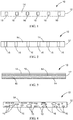
FIG. 1 through FIG. 4 , a ceramic matrixcomposite component layer 10 includes a ceramicmatrix composite ply 12 and a bond-inhibitingcoating 14 on a portion of one surface of the ceramicmatrix composite ply 12. The bond-inhibitingcoating 14 is preferably as thin as possible while still inhibiting bonding between the coated surface of theCMC ply 12 and the neighboringCMC ply 12. In some embodiments, the thickness of the bond-inhibitingcoating 14 is in the range of about 1% to about 10% of the thickness of theCMC ply 12. TheCMC ply 12 preferably has a length and a width that are each at least an order of magnitude greater than the thickness of theCMC ply 12.Bonding surfaces 16 of theCMC component layer 10 are not coated by the bond-inhibitingcoating 14. Thebonding surfaces 16 may have any shape, including, but not limited to, one or more squares or rectangles as shown inFIG. 1 , one or more stripes across the width of theCMC ply 12 as shown inFIG. 2 , one or more stripes across the length of theCMC ply 12 as shown inFIG. 3 , one or more circles or ovals as shown inFIG. 4 , or combinations thereof, and may be regularly, irregularly, or randomly spaced or sized. - As shown in
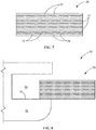
FIG. 5 , a ceramicmatrix composite component 20 is formed when a set of ceramicmatrix composite plies 12 with bond-inhibitingcoatings 14 are bonded together in a stack. When used as a seal, theCMC component 20 preferably has athickness 26 in the range of about 1.25 to about 5 mm (0.050 to 0.200 inches). The average ply thickness and number ofCMC plies 12 in aCMC component 20 may vary depending on the type of fiber being used and the amount of matrix material being used per ply. In some embodiments, the average ply thickness in theCMC component 20 is in the range of about 0.1 to about 0.25 mm (about 4 to about 10 mil) and the number of layers ofCMC plies 12 in theCMC component 20 is in the range of about 5 to about 50. The ceramicmatrix composite component 20 includes areas of bonding 22 between neighboring ceramicmatrix composite plies 12 separated by areas of non-bonding 24 between neighboring ceramicmatrix composite plies 12. - Alternative patterns of
bonded areas 22 and non-bondedarea 24 between neighboring ceramicmatrix composite plies 12 are shown inFIG. 6 andFIG. 7 , but other patterns or irregular arrangements may alternatively be successfully implemented. - Adjustments to the size, spacing, or locations of the areas of bonding 22 on the
CMC plies 12 may be used to tune or optimize the flexibility of aCMC component 20 formed from theCMC plies 12 for a specific application, such as in the gasturbine seal assembly 50 shown inFIG. 8 . The ceramicmatrix composite component 20 may serve as a gas turbine seal component of the gasturbine seal assembly 50 by contacting asealing surface 52 in aseal slot 54 of agas turbine component 56 and forming a seal with thesurface 52 of thegas turbine component 56. - A high-
temperature CMC component 20 preferably includes bondedareas 22 as well as non-bondedareas 24 of neighboring plies to provide flexibility to the seal. The selective bonding increases the flexibility of the seal. A bond-inhibitingcoating 14 between portions ofCMC plies 12 prevents bonding of theCMC plies 12 at the locations of the bond-inhibitingcoating 14. In some embodiments, the bond-inhibitingcoating 14 includes a nitride. In some embodiments, the nitride is boron nitride (BN). - In some embodiments, the nitride is silicon nitride (Si3N4). In some embodiments, the bond-inhibiting
coating 14 is a paste including a nitride powder mixed with a liquid. The gasturbine seal assembly 50 preferably does not include any spacers beyond the bond-inhibitingcoating 14 or large gaps or voids between theCMC plies 12. - Examples of CMC materials include, but are not limited to, carbon-fiber-reinforced carbon (C/C), carbon-fiber-reinforced silicon carbide (C/SiC), silicon-carbide-fiber-reinforced silicon carbide (SiC/SiC), alumina-fiber-reinforced alumina (Al2O3/Al2O3), or combinations thereof. The CMC may have increased elongation, fracture toughness, thermal shock, dynamic load capability, and anisotropic properties as compared to a monolithic ceramic structure.
- The
CMC plies 12 are preferably unidirectional fiber plies with the direction of orientation of the fibers changing from one layer to the next in the stack ofCMC plies 12 of theCMC component 20. The change in orientation between layers may be selected to reduce torsional stiffness or to provide a predetermined level of stiffness in theCMC component 20. In some embodiments, the change in orientation is +/- 45 degrees. In other embodiments, the fibers of aCMC ply 12 may be cross-weaved. - In some embodiments, prior to contacting and selectively bonding the surfaces of each pair of neighboring CMC plies 12, only one of the two contacting surfaces is selectively coated with a bond-inhibiting
coating 14 and the other contacting surface is left uncoated. The bond-inhibitingcoating 14 may be applied by any suitable apparatus, including, but not limited to, a paint brush or a spray gun. In some embodiments, this is achieved by having one uncoated side and one selectively-coated side for each of the CMC plies 12, except for one of the end CMC plies 12, which may be uncoated on both sides. In other embodiments, this is achieved by having alternating CMC plies 12 with both sides uncoated and CMC plies 12 with both sides selectively coated. In other embodiments, combinations of these two strategies may be used. - A selectively-applied bond-inhibiting
coating 14 preferably covers at least 50%, alternatively at least 60%, alternatively at least 70%, alternatively at least 80%, alternatively at least 90%, alternatively in the range of 50 to 90%, alternatively in the range of 60 to 90%, alternatively in the range of 70 to 90%, alternatively in the range of 80 to 90%, or ranges or sub-ranges therebetween, of the area of a selectively-coated surface, with the balance of the surface area preferably serving as the bonding surfaces 16. - The bonding surfaces 16 of the selectively-coated surface are preferably discrete areas separated from each other by the bond-inhibiting
coating 14. The shapes of the bonding surfaces 16 may be any suitable shapes, including, but not limited to, a square, a rectangle, a triangle, a circle, an oval, a straight line, a curved line, or combinations thereof. The sizes and shapes of the bonding surfaces 16 on a surface of aCMC ply 12 may be all the same or some may differ from others. The spacings between the bonding surfaces 16 on a surface of aCMC ply 12 may be regular or irregular. - In some embodiments, a method of forming a
CMC component 20 includes selectively applying a bond-inhibitingcoating 14 to at least one non-bonding portion of at least one of the two main surfaces of at least one of a set of CMC plies 12. The method also includes bonding the set of CMC plies 12 together to form theCMC component 20. The bonding may be done under any conventional CMC bonding conditions, with the bonding portions of the main surfaces bonded to the surfaces of the neighboring CMC ply 12. In some embodiments, the CMC plies 12 are bonding during the infiltration process. The bond-inhibitingcoating 14 prevents bonding between the non-bonding portions of the selectively-coated surface and the neighboring CMC ply 12. Typically, at least a portion of the bond-inhibitingcoating 14 remains between the CMC plies 12 after the bonding of the CMC plies 12. In some embodiments, the method further includes forming the CMC plies 12. In some embodiments, the method further includes inserting a portion of theCMC component 20 into aseal slot 54 of a sealingsurface 52 of a gasturbine seal assembly 50. Thenon-bonded areas 24 of theCMC component 20 preferably provide a flexibility to theCMC component 20 in the thickness direction of theCMC component 20 greater than a flexibility of aCMC component 20 without anynon-bonded areas 24. - While the invention has been described with reference to one or more embodiments, it will be understood by those skilled in the art that various changes may be made and equivalents may be substituted for elements thereof without departing from the scope of the invention. In addition, many modifications may be made to adapt a particular situation or material to the teachings of the invention without departing from the essential scope thereof. Therefore, it is intended that the invention not be limited to the particular embodiment disclosed but that the invention will include all embodiments falling within the scope of the appended claims. In addition, all numerical values identified in the detailed description shall be interpreted as though the precise and approximate values are both expressly identified.
- Various aspects and embodiments of the present invention are defined by the following numbered clauses:
- 1. A method of forming a ceramic matrix composite component comprising:
- selectively applying a bond-inhibiting coating to at least one non-bonding portion of at least one first surface of at least one of a plurality of ceramic matrix composite plies; and
- bonding the plurality of ceramic matrix composite plies together to form the ceramic matrix composite component such that at least one bonding portion of the at least one first surface lacking the bond-inhibiting coating bonds to a second surface of a neighboring ceramic matrix composite ply of the plurality of ceramic matrix composite plies and the bond-inhibiting coating prevents bonding between the non-bonding portion of the at least one first surface and the second surface.
- 2. The method of
clause 1, further comprising forming the plurality of ceramic matrix composite plies. - 3. The method of any preceding clause, wherein the at least one bonding portion comprises a plurality of bonding portions separated by non-bonding portions on the first surface.
- 4. The method of any preceding clause, wherein each pair of neighboring ceramic matrix composite plies comprises the first surface and the second surface.
- 5. The method of any preceding clause, wherein a presence of the at least one non-bonding portion increases a flexibility of the ceramic matrix composite component relative to a ceramic matrix composite component lacking the non-bonding portion.
- 6. The method of any preceding clause, wherein the ceramic matrix composite component has no spacers between the plurality of ceramic matrix composite plies beyond the bond-inhibiting coatings.
- 7. The method of any preceding clause, wherein the ceramic matrix composite plies comprise a ceramic matrix composite selected from the group consisting of carbon-fiber-reinforced carbon, carbon-fiber-reinforced silicon carbide, silicon-carbide-fiber-reinforced silicon carbide, alumina-fiber-reinforced alumina, and any combination thereof.
- 8. The method of any preceding clause, wherein the bond-inhibiting coating comprises a nitride selected from the group consisting of boron nitride and silicon nitride.
- 9. The method of any preceding clause, wherein the ceramic matrix composite component comprises a gas turbine seal component.
- 10. A ceramic matrix composite component comprising:
- a plurality of ceramic matrix composite plies bonded together to form the ceramic matrix composite component, wherein a bond-inhibiting coating on at least one non-bonding portion of at least one first surface of at least one of the plurality of ceramic matrix composite plies prevents bonding between the non-bonding portion of the at least one first surface and a second surface of a neighboring ceramic matrix composite ply of the plurality of ceramic matrix composite plies, and at least one bonding portion of the at least one first surface lacking the bond-inhibiting coating is bonded to the second surface.
- 11. The ceramic matrix composite component of any preceding clause, wherein the at least one bonding portion comprises a plurality of bonding portions on the first surface.
- 12. The ceramic matrix composite component of any preceding clause, wherein each pair of neighboring ceramic matrix composite plies comprises the first surface and the second surface.
- 13. The ceramic matrix composite component of any preceding clause, wherein a presence of the at least one non-bonding portion increases a flexibility of the ceramic matrix composite component relative to a ceramic matrix composite component lacking the non-bonding portion.
- 14. The ceramic matrix composite component of any preceding clause, wherein the ceramic matrix composite component has no spacers between the plurality of ceramic matrix composite plies beyond the bond-inhibiting coatings.
- 15. The ceramic matrix composite component of any preceding clause, wherein the ceramic matrix composite plies comprise a ceramic matrix composite selected from the group consisting of carbon-fiber-reinforced carbon, carbon-fiber-reinforced silicon carbide, silicon-carbide-fiber-reinforced silicon carbide, alumina-fiber-reinforced alumina, and any combination thereof.
- 16. The ceramic matrix composite component of any preceding clause, wherein the bond-inhibiting coating comprises a nitride selected from the group consisting of boron nitride and silicon nitride.
- 17. The ceramic matrix composite component of any preceding clause, wherein the ceramic matrix composite component comprises a gas turbine seal component.
- 18. A gas turbine seal assembly comprising:
- a gas turbine component; and
- a gas turbine seal component contacting the gas turbine component to form a seal between the gas turbine component and the gas turbine seal component, the gas turbine seal component comprising a plurality of ceramic matrix composite plies bonded together to form a ceramic matrix composite component, wherein a bond-inhibiting coating on at least one non-bonding portion of at least one first surface of at least one of the plurality of ceramic matrix composite plies prevents bonding between the non-bonding portion of the at least one first surface and a second surface of a neighboring ceramic matrix composite ply of the plurality of ceramic matrix composite plies, and at least one bonding portion of the at least one first surface lacking the bond-inhibiting coating is bonded to the second surface.
- 19. The gas turbine seal assembly of any preceding clause, wherein each pair of neighboring ceramic matrix composite plies comprises the first surface and the second surface.
- 20. The gas turbine seal assembly of any preceding clause, wherein the gas turbine seal component has no spacers between the plurality of ceramic matrix composite plies beyond the bond-inhibiting coatings.
Claims (10)
- A method of forming a ceramic matrix composite component (20) comprising:selectively applying a bond-inhibiting coating (14) to at least one non-bonding portion (24) of at least one first surface of at least one of a plurality of ceramic matrix composite plies (12); andbonding the plurality of ceramic matrix composite plies (12) together to form the ceramic matrix composite component (20) such that at least one bonding portion (16) of the at least one first surface lacking the bond-inhibiting coating (14) bonds to a second surface of a neighboring ceramic matrix composite ply (12) of the plurality of ceramic matrix composite plies (12) and the bond-inhibiting coating (14) prevents bonding between the non-bonding portion (24) of the at least one first surface and the second surface.
- The method of claim 1, further comprising forming the plurality of ceramic matrix composite plies (12).
- The method of claim 1 or 2, wherein a presence of the at least one non-bonding portion (24) increases a flexibility of the ceramic matrix composite component (20) relative to a ceramic matrix composite component (20) lacking the non-bonding portion (24).
- The method of claim 1, 2 or 3, wherein the ceramic matrix composite component (20) has no spacers between the plurality of ceramic matrix composite plies (12) beyond the bond-inhibiting coatings (14).
- A ceramic matrix composite component (20) comprising:a plurality of ceramic matrix composite plies (12) bonded together to form the ceramic matrix composite component (20), wherein a bond-inhibiting coating (14) on at least one non-bonding portion (24) of at least one first surface of at least one of the plurality of ceramic matrix composite plies (12) prevents bonding between the non-bonding portion (24) of the at least one first surface and a second surface of a neighboring ceramic matrix composite ply (12) of the plurality of ceramic matrix composite plies (12), and at least one bonding portion (16) of the at least one first surface lacking the bond-inhibiting coating (14) is bonded to the second surface.
- The ceramic matrix composite component (20) of claim 5, wherein each pair of neighboring ceramic matrix composite plies (12) comprises the first surface and the second surface.
- The ceramic matrix composite component (20) of claim 5 or 6, wherein the ceramic matrix composite component (20) has no spacers between the plurality of ceramic matrix composite plies (12) beyond the bond-inhibiting coatings (14).
- The ceramic matrix composite component (20) of claim 5, 6 or 7, wherein the bond-inhibiting coating (14) comprises a nitride selected from the group consisting of boron nitride and silicon nitride.
- The ceramic matrix composite component (20) of any of claims 5 to 8, wherein the ceramic matrix composite component (20) comprises a gas turbine seal component (56).
- A gas turbine seal assembly (50) comprising:a gas turbine component (56); anda gas turbine seal component (56) contacting the gas turbine component (50) to form a seal between the gas turbine component (50) and the gas turbine seal component (50), the gas turbine seal component (50) comprising a plurality of ceramic matrix composite plies (12) bonded together to form a ceramic matrix composite component (20), wherein a bond-inhibiting coating (14) on at least one non-bonding portion (24) of at least one first surface of at least one of the plurality of ceramic matrix composite plies (12) prevents bonding between the non-bonding portion (24) of the at least one first surface and a second surface of a neighboring ceramic matrix composite ply (12) of the plurality of ceramic matrix composite plies (12), and at least one bonding portion (16) of the at least one first surface lacking the bond-inhibiting coating (14) is bonded to the second surface.
Applications Claiming Priority (1)
| Application Number | Priority Date | Filing Date | Title |
|---|---|---|---|
| US15/064,801 US20170260867A1 (en) | 2016-03-09 | 2016-03-09 | Ceramic matrix composite component, gas turbine seal assembly, and method of forming ceramic matrix composite component |
Publications (1)
| Publication Number | Publication Date |
|---|---|
| EP3216772A1 true EP3216772A1 (en) | 2017-09-13 |
Family
ID=58264413
Family Applications (1)
| Application Number | Title | Priority Date | Filing Date |
|---|---|---|---|
| EP17159330.4A Withdrawn EP3216772A1 (en) | 2016-03-09 | 2017-03-06 | Ceramic matrix composite component,gas turbine seal assembly, and method of forming ceramic matrix composite component |
Country Status (3)
| Country | Link |
|---|---|
| US (1) | US20170260867A1 (en) |
| EP (1) | EP3216772A1 (en) |
| JP (1) | JP2017200869A (en) |
Families Citing this family (2)
| Publication number | Priority date | Publication date | Assignee | Title |
|---|---|---|---|---|
| US20200095880A1 (en) * | 2018-09-24 | 2020-03-26 | United Technologies Corporation | Featherseal formed of cmc materials |
| US11041399B2 (en) | 2019-11-01 | 2021-06-22 | Raytheon Technologies Corporation | CMC heat shield |
Citations (3)
| Publication number | Priority date | Publication date | Assignee | Title |
|---|---|---|---|---|
| EP1432571A2 (en) * | 2001-09-26 | 2004-06-30 | Siemens Westinghouse Power Corporation | Hybrid ceramic material composed of insulating and structural ceramic layers |
| EP2052853A2 (en) * | 2007-10-26 | 2009-04-29 | Coi Ceramics, Inc. | Flexible ceramic matrix composite structures and methods of forming the same |
| US20100074729A1 (en) * | 2008-09-22 | 2010-03-25 | Siemens Energy, Inc. | Compressible Ceramic Seal |
Family Cites Families (1)
| Publication number | Priority date | Publication date | Assignee | Title |
|---|---|---|---|---|
| US5645673A (en) * | 1995-06-02 | 1997-07-08 | International Business Machines Corporation | Lamination process for producing non-planar substrates |
-
2016
- 2016-03-09 US US15/064,801 patent/US20170260867A1/en not_active Abandoned
-
2017
- 2017-02-24 JP JP2017032756A patent/JP2017200869A/en active Pending
- 2017-03-06 EP EP17159330.4A patent/EP3216772A1/en not_active Withdrawn
Patent Citations (3)
| Publication number | Priority date | Publication date | Assignee | Title |
|---|---|---|---|---|
| EP1432571A2 (en) * | 2001-09-26 | 2004-06-30 | Siemens Westinghouse Power Corporation | Hybrid ceramic material composed of insulating and structural ceramic layers |
| EP2052853A2 (en) * | 2007-10-26 | 2009-04-29 | Coi Ceramics, Inc. | Flexible ceramic matrix composite structures and methods of forming the same |
| US20100074729A1 (en) * | 2008-09-22 | 2010-03-25 | Siemens Energy, Inc. | Compressible Ceramic Seal |
Also Published As
| Publication number | Publication date |
|---|---|
| JP2017200869A (en) | 2017-11-09 |
| US20170260867A1 (en) | 2017-09-14 |
Similar Documents
| Publication | Publication Date | Title |
|---|---|---|
| US10626745B2 (en) | Turbine ring assembly supported by flanges | |
| US8974891B2 (en) | Thermal protection systems comprising flexible regions of inter-bonded lamina of ceramic matrix composite material and methods of forming the same | |
| US7153096B2 (en) | Stacked laminate CMC turbine vane | |
| US9822655B2 (en) | Assembly formed by a turbine nozzle or a compressor diffuser made of CMC for a turbine engine and by an abradable material support ring, and a turbine or a compressor incorporating such an assembly | |
| US10487670B2 (en) | Gas turbine engine component including a compliant layer | |
| CN103206265B (en) | For the grid adhesive layer that the continuous fiber of barrier of environment coat system is strengthened | |
| US9527262B2 (en) | Layered arrangement, hot-gas path component, and process of producing a layered arrangement | |
| US7247002B2 (en) | Lamellate CMC structure with interlock to metallic support structure | |
| US20180029944A1 (en) | Ceramic matrix composite turbine component with engineered surface features retaining a thermal barrier coat | |
| US10294802B2 (en) | Turbine engine components with chemical vapor infiltrated isolation layers | |
| JP2016537548A (en) | Method for producing a silica shaped article having a processed surface that improves creep slip resistance under high temperature loads | |
| EP3216772A1 (en) | Ceramic matrix composite component,gas turbine seal assembly, and method of forming ceramic matrix composite component | |
| RU2770128C2 (en) | Part containing protective coating with gradually changing composition | |
| US11384646B2 (en) | Method for forming hollow ceramic matrix composite article using a mandrel | |
| US10538463B2 (en) | Composite ceramic comprising a corrosion protection layer and production method | |
| EP3266607B1 (en) | Fiber-reinforced resin structure and method for producing fiber-reinforced resin structure | |
| US9290836B2 (en) | Crack-resistant environmental barrier coatings | |
| EP3176532B1 (en) | Heat exchanger | |
| CH711017B1 (en) | Sealing arrangement for turbo machinery. |
Legal Events
| Date | Code | Title | Description |
|---|---|---|---|
| PUAI | Public reference made under article 153(3) epc to a published international application that has entered the european phase |
Free format text: ORIGINAL CODE: 0009012 |
|
| AK | Designated contracting states |
Kind code of ref document: A1 Designated state(s): AL AT BE BG CH CY CZ DE DK EE ES FI FR GB GR HR HU IE IS IT LI LT LU LV MC MK MT NL NO PL PT RO RS SE SI SK SM TR |
|
| AX | Request for extension of the european patent |
Extension state: BA ME |
|
| 17P | Request for examination filed |
Effective date: 20180313 |
|
| RBV | Designated contracting states (corrected) |
Designated state(s): AL AT BE BG CH CY CZ DE DK EE ES FI FR GB GR HR HU IE IS IT LI LT LU LV MC MK MT NL NO PL PT RO RS SE SI SK SM TR |
|
| 17Q | First examination report despatched |
Effective date: 20190218 |
|
| STAA | Information on the status of an ep patent application or granted ep patent |
Free format text: STATUS: THE APPLICATION IS DEEMED TO BE WITHDRAWN |
|
| 18D | Application deemed to be withdrawn |
Effective date: 20190629 |