EP3216636A1 - Refrigeration system and method - Google Patents
Refrigeration system and method Download PDFInfo
- Publication number
- EP3216636A1 EP3216636A1 EP17159931.9A EP17159931A EP3216636A1 EP 3216636 A1 EP3216636 A1 EP 3216636A1 EP 17159931 A EP17159931 A EP 17159931A EP 3216636 A1 EP3216636 A1 EP 3216636A1
- Authority
- EP
- European Patent Office
- Prior art keywords
- refrigeration system
- refrigerant
- control
- pressurised
- controller
- Prior art date
- Legal status (The legal status is an assumption and is not a legal conclusion. Google has not performed a legal analysis and makes no representation as to the accuracy of the status listed.)
- Withdrawn
Links
Images
Classifications
-
- F—MECHANICAL ENGINEERING; LIGHTING; HEATING; WEAPONS; BLASTING
- F25—REFRIGERATION OR COOLING; COMBINED HEATING AND REFRIGERATION SYSTEMS; HEAT PUMP SYSTEMS; MANUFACTURE OR STORAGE OF ICE; LIQUEFACTION SOLIDIFICATION OF GASES
- F25B—REFRIGERATION MACHINES, PLANTS OR SYSTEMS; COMBINED HEATING AND REFRIGERATION SYSTEMS; HEAT PUMP SYSTEMS
- F25B19/00—Machines, plants or systems, using evaporation of a refrigerant but without recovery of the vapour
- F25B19/005—Machines, plants or systems, using evaporation of a refrigerant but without recovery of the vapour the refrigerant being a liquefied gas
-
- B—PERFORMING OPERATIONS; TRANSPORTING
- B60—VEHICLES IN GENERAL
- B60P—VEHICLES ADAPTED FOR LOAD TRANSPORTATION OR TO TRANSPORT, TO CARRY, OR TO COMPRISE SPECIAL LOADS OR OBJECTS
- B60P3/00—Vehicles adapted to transport, to carry or to comprise special loads or objects
- B60P3/20—Refrigerated goods vehicles
-
- B—PERFORMING OPERATIONS; TRANSPORTING
- B60—VEHICLES IN GENERAL
- B60H—ARRANGEMENTS OF HEATING, COOLING, VENTILATING OR OTHER AIR-TREATING DEVICES SPECIALLY ADAPTED FOR PASSENGER OR GOODS SPACES OF VEHICLES
- B60H1/00—Heating, cooling or ventilating devices
- B60H1/00007—Combined heating, ventilating, or cooling devices
- B60H1/00014—Combined heating, ventilating, or cooling devices for load cargos on load transporting vehicles
-
- B—PERFORMING OPERATIONS; TRANSPORTING
- B60—VEHICLES IN GENERAL
- B60H—ARRANGEMENTS OF HEATING, COOLING, VENTILATING OR OTHER AIR-TREATING DEVICES SPECIALLY ADAPTED FOR PASSENGER OR GOODS SPACES OF VEHICLES
- B60H1/00—Heating, cooling or ventilating devices
- B60H1/32—Cooling devices
- B60H1/3202—Cooling devices using evaporation, i.e. not including a compressor, e.g. involving fuel or water evaporation
-
- B—PERFORMING OPERATIONS; TRANSPORTING
- B65—CONVEYING; PACKING; STORING; HANDLING THIN OR FILAMENTARY MATERIAL
- B65D—CONTAINERS FOR STORAGE OR TRANSPORT OF ARTICLES OR MATERIALS, e.g. BAGS, BARRELS, BOTTLES, BOXES, CANS, CARTONS, CRATES, DRUMS, JARS, TANKS, HOPPERS, FORWARDING CONTAINERS; ACCESSORIES, CLOSURES, OR FITTINGS THEREFOR; PACKAGING ELEMENTS; PACKAGES
- B65D88/00—Large containers
- B65D88/74—Large containers having means for heating, cooling, aerating or other conditioning of contents
- B65D88/744—Large containers having means for heating, cooling, aerating or other conditioning of contents heating or cooling through the walls or internal parts of the container, e.g. circulation of fluid inside the walls
-
- F—MECHANICAL ENGINEERING; LIGHTING; HEATING; WEAPONS; BLASTING
- F25—REFRIGERATION OR COOLING; COMBINED HEATING AND REFRIGERATION SYSTEMS; HEAT PUMP SYSTEMS; MANUFACTURE OR STORAGE OF ICE; LIQUEFACTION SOLIDIFICATION OF GASES
- F25D—REFRIGERATORS; COLD ROOMS; ICE-BOXES; COOLING OR FREEZING APPARATUS NOT OTHERWISE PROVIDED FOR
- F25D16/00—Devices using a combination of a cooling mode associated with refrigerating machinery with a cooling mode not associated with refrigerating machinery
-
- F—MECHANICAL ENGINEERING; LIGHTING; HEATING; WEAPONS; BLASTING
- F25—REFRIGERATION OR COOLING; COMBINED HEATING AND REFRIGERATION SYSTEMS; HEAT PUMP SYSTEMS; MANUFACTURE OR STORAGE OF ICE; LIQUEFACTION SOLIDIFICATION OF GASES
- F25D—REFRIGERATORS; COLD ROOMS; ICE-BOXES; COOLING OR FREEZING APPARATUS NOT OTHERWISE PROVIDED FOR
- F25D29/00—Arrangement or mounting of control or safety devices
- F25D29/001—Arrangement or mounting of control or safety devices for cryogenic fluid systems
-
- F—MECHANICAL ENGINEERING; LIGHTING; HEATING; WEAPONS; BLASTING
- F25—REFRIGERATION OR COOLING; COMBINED HEATING AND REFRIGERATION SYSTEMS; HEAT PUMP SYSTEMS; MANUFACTURE OR STORAGE OF ICE; LIQUEFACTION SOLIDIFICATION OF GASES
- F25D—REFRIGERATORS; COLD ROOMS; ICE-BOXES; COOLING OR FREEZING APPARATUS NOT OTHERWISE PROVIDED FOR
- F25D3/00—Devices using other cold materials; Devices using cold-storage bodies
- F25D3/10—Devices using other cold materials; Devices using cold-storage bodies using liquefied gases, e.g. liquid air
- F25D3/105—Movable containers
-
- F—MECHANICAL ENGINEERING; LIGHTING; HEATING; WEAPONS; BLASTING
- F25—REFRIGERATION OR COOLING; COMBINED HEATING AND REFRIGERATION SYSTEMS; HEAT PUMP SYSTEMS; MANUFACTURE OR STORAGE OF ICE; LIQUEFACTION SOLIDIFICATION OF GASES
- F25D—REFRIGERATORS; COLD ROOMS; ICE-BOXES; COOLING OR FREEZING APPARATUS NOT OTHERWISE PROVIDED FOR
- F25D7/00—Devices using evaporation effects without recovery of the vapour
-
- B—PERFORMING OPERATIONS; TRANSPORTING
- B60—VEHICLES IN GENERAL
- B60H—ARRANGEMENTS OF HEATING, COOLING, VENTILATING OR OTHER AIR-TREATING DEVICES SPECIALLY ADAPTED FOR PASSENGER OR GOODS SPACES OF VEHICLES
- B60H1/00—Heating, cooling or ventilating devices
- B60H1/32—Cooling devices
- B60H1/3204—Cooling devices using compression
-
- F—MECHANICAL ENGINEERING; LIGHTING; HEATING; WEAPONS; BLASTING
- F17—STORING OR DISTRIBUTING GASES OR LIQUIDS
- F17C—VESSELS FOR CONTAINING OR STORING COMPRESSED, LIQUEFIED OR SOLIDIFIED GASES; FIXED-CAPACITY GAS-HOLDERS; FILLING VESSELS WITH, OR DISCHARGING FROM VESSELS, COMPRESSED, LIQUEFIED, OR SOLIDIFIED GASES
- F17C2221/00—Handled fluid, in particular type of fluid
- F17C2221/01—Pure fluids
- F17C2221/013—Carbon dioxide
-
- F—MECHANICAL ENGINEERING; LIGHTING; HEATING; WEAPONS; BLASTING
- F17—STORING OR DISTRIBUTING GASES OR LIQUIDS
- F17C—VESSELS FOR CONTAINING OR STORING COMPRESSED, LIQUEFIED OR SOLIDIFIED GASES; FIXED-CAPACITY GAS-HOLDERS; FILLING VESSELS WITH, OR DISCHARGING FROM VESSELS, COMPRESSED, LIQUEFIED, OR SOLIDIFIED GASES
- F17C2250/00—Accessories; Control means; Indicating, measuring or monitoring of parameters
- F17C2250/04—Indicating or measuring of parameters as input values
- F17C2250/0404—Parameters indicated or measured
- F17C2250/0439—Temperature
-
- F—MECHANICAL ENGINEERING; LIGHTING; HEATING; WEAPONS; BLASTING
- F17—STORING OR DISTRIBUTING GASES OR LIQUIDS
- F17C—VESSELS FOR CONTAINING OR STORING COMPRESSED, LIQUEFIED OR SOLIDIFIED GASES; FIXED-CAPACITY GAS-HOLDERS; FILLING VESSELS WITH, OR DISCHARGING FROM VESSELS, COMPRESSED, LIQUEFIED, OR SOLIDIFIED GASES
- F17C2270/00—Applications
- F17C2270/01—Applications for fluid transport or storage
- F17C2270/0165—Applications for fluid transport or storage on the road
- F17C2270/0168—Applications for fluid transport or storage on the road by vehicles
- F17C2270/0171—Trucks
Definitions
- the present invention relates to a refrigeration system and method and in particular one that is particularly suitable for use in vehicular deliveries.
- Deliveries of items needing refrigeration is a common activity. Lorries and vans involved in such deliveries typically include a refrigerated compartment that is cooled by a refrigeration unit mounted on the roof, behind the cab or in some other suitable place.
- a refrigeration unit typically includes a compressor that drives coolant around a closed circuit.
- the refrigeration system is powered by the vehicle's engine or has a dedicated engine to power it.
- a refrigeration system including a refrigerant source, a controller and a heat exchanger, wherein the refrigerant source is arranged to receive a feed of refrigerant and is arranged to vent the refrigerant under control of the controller via the heat exchanger and out of the refrigeration system.
- the refrigerant feed preferably comprises a pressurised vessel.
- the pressurised vessel may comprises a bottle or canister.
- the pressurised vessel is replaceable.
- the pressurised vessel is a user replaceable consumable.
- the refrigerant feed may comprise a plurality of pressurised vessels that may be operable automatically or manually, individually, collectively, selectively and/or under some programmed or controlled sequence.
- each of the plurality of pressurised vessels is controllable separately by the controller and is replaceable independently of the others of the plurality of pressurised vessels.
- the refrigerant comprises carbon dioxide stored under pressure as a liquid.
- the controller may include a first control operable to trigger operation of the refrigeration system.
- the controller may include a second control that controls dispensing and venting of the refrigerant over time.
- the second control may control rate of escape of the refrigerant in dependence on a desired temperature.
- the refrigeration system may further comprise a temperature sensor positioned in an area to be refrigerated by the refrigeration system or around the heat exchanger, the temperature sensor being arranged to communicate with the second control to regulate the rate of escape in dependence on temperature measured by the temperature sensor.
- the refrigeration system is preferably a backup installable in parallel to a primary refrigeration system and is triggerable upon failure of the primary refrigeration system. This may be a manual or automatic action or some combination of the two.
- a refrigeration method comprising:
- the refrigeration system is a "total loss" refrigeration system in which the refrigerant is lost to the atmosphere as it is vented.
- the refrigerant is only used once (although clearly it could be recaptured from the atmosphere).
- the refrigerant feed comprises a pressurised vessel such as a bottle or canister.
- the refrigerant comprises carbon dioxide stored under pressure as a liquid. It will be appreciated that other refrigerants with similar physical properties may be used. Components of the refrigeration system are preferably selected so as to stand high pressures encountered due to use of carbon dioxide as a coolant.
- the controller may include a first control that is operable to trigger operation of the refrigeration system and optionally a second control that controls dispensing and venting of the refrigerant over time.
- the first control may be a valve, handle or push button that opens a valve and allows the liquified carbon dioxide to escape from the pressurised vessel and as it does so boil and impart cooling to the environment via the heat exchanger.
- the second control preferably controls rate of escape of the refrigerant in dependence on a desired temperature.
- a thermostat or other temperature probe may be positioned in the refrigerated area or around the heat exchanger and used to regulate rate of escape (bleed rate) of the refrigerant.
- bleed rate rate of escape
- multiple temperatures may be monitored and the bleed rate controlled to make optimal use of the refrigerant.
- the refrigeration system may provide approximately 2 hours of refrigeration so as to be able to act as an emergency refrigeration source.
- the refrigeration system is installed as a backup in parallel to a primary, for example battery or vehicular powered, refrigeration system.
- the backup refrigeration system can be triggered via the first control in the event of failure of the primary system being detected or reported.
- the first control may be installed in the vehicle cab alongside warning lights or other monitoring systems for the primary system.
- the vessel is user-replaceable.
- the pressurised bottles may be sold as consumables or as refillable and returnable sources of the refrigerant.
- a number of bottles may be stored in a vehicle, cab etc and swapped out as needed.
- the bottles can be kept long-term with the system held in reserve in case the primary system fails.
- the emergency refrigeration provided may be sufficient to get the primary system repaired, get the vehicle to somewhere with a suitable refrigeration unit etc.
- the backup refrigeration system may provide sufficient refrigeration (particularly if there are multiple bottles available to be swapped out) to continue and complete the journey.
- the system is configured such that the refrigerant boils at a temperature a little lower than the temperature to be maintained and the heat exchanger preferably functions such that the last drops of refrigerant boil off just before they leave the heat exchanger. This maximises the energy absorbed from the change of state of the refrigerant i.e. its latent heat of evaporation.
- the heat exchanger is preferably configured to not only take advantage of the latent heat of evaporation of the refrigerant liquid but also to utilise as much as possible the specific heat capacity of the gas as its temperature is brought back up as close as possible to the temperature to be maintained. This means that only a small part of the heat exchanger will be used to boil the refrigerant and the larger part being used to absorb heat directly through the change of temperature of the gas.
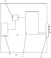
- Figure 1 is a schematic diagram of a refrigeration system according to an embodiment.
- the refrigeration system 10 includes a refrigerant source 20, a controller 30 and a heat exchanger 40.
- the refrigerant source 20 is arranged to receive a feed of refrigerant and is arranged to vent the refrigerant under control of the controller 30 via the heat exchanger 40 and out of the refrigeration system via an exhaust or vent 50.
- the refrigerant source 20 is a user replaceable bottle of pressurised carbon dioxide.
- the refrigeration system is a "total loss" refrigeration system in which the refrigerant is lost to the atmosphere as it is vented.
- the controller 30 When the refrigeration is needed (for example it is expected that the refrigeration system would be installed as a backup in parallel to a primary refrigeration system for situations where the primary refrigeration system fails or is degraded), it is triggered via the controller 30.
- This may be a manual or automatic action or some combination of the two.
- there may be a manual lever, valve, handle or button to open a valve to the pressurised.
- the pressurised (preferably liquefied) carbon dioxide escapes from the pressurised vessel 20 due to pressure differential and as it does so it boils and imparts cooling to the environment via the heat exchanger 40.
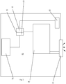
- Figure 2 is a schematic diagram of the refrigeration system of Figure 1 illustrating selected further optional features according to another embodiment.
- the refrigeration system 10 includes a temperature sensor 60 and the controller 30 includes first 31 and second 32 controls.
- the first control 31 operates as described above in connection with Figure 1 to control operation of the refrigeration system 10 by controlling escape of the refrigerant into the refrigeration system 10.
- the second control 32 controls rate of escape of the refrigerant.
- one factor taken into account by the second control 32 is a desired temperature.
- the temperature sensor 60 may be a thermostat or other temperature probe which is positioned in the refrigerated area or around the heat exchanger 40.
- the temperature sensor 60 is arranged to communicate with the second control (for example by a piped wired or wireless link) to provide temperature measurements or some other measure of deviation from the desired temperature.
- the second control 32 uses the received data to regulate rate of escape (bleed rate) of the refrigerant.
- rate of escape bleed rate
- multiple temperatures may be monitored and the bleed rate controlled to make optimal use of the refrigerant.
- the second control 32 may also take into account other factors such as operational tolerances of the refrigeration system 10 and environmental limits on venting refrigerant.
- the second control 32 may operate as a feedback or feed forward controller, may include fuzzy logic control or utilize other control system techniques to regulate refrigerant flow against desired goals.
- the refrigerant source 20 may be a bank of pressurised bottles that can be drawn upon by the controller 30 to provide refrigerant as needed.
- their respective refrigerant could be vented sequentially or under some circumstances they may be drawn upon in parallel or all together.
- the controller may be configurable with a desired run-time (for example the driver may know how long to destination or until a repair team arrives) and in such circumstances the controller may tune bleed rate to optimally provide refrigerant over that period. It may be that a display of estimated run-time is provided that is adjusted by the controller as the refrigeration system operates.
- An associated "desired temperature” control may also be provided such that a user can see the estimated run time based on desired temperature. This may also take into account ambient temperature sensed by the temperature sensor or other sensor(s), capacity of the refrigerated space, estimated cooling capability of the refrigerant (which may be updated once the system actually operates) etc.
Landscapes
- Engineering & Computer Science (AREA)
- Mechanical Engineering (AREA)
- Physics & Mathematics (AREA)
- Thermal Sciences (AREA)
- General Engineering & Computer Science (AREA)
- Chemical & Material Sciences (AREA)
- Combustion & Propulsion (AREA)
- Health & Medical Sciences (AREA)
- Public Health (AREA)
- Transportation (AREA)
- Devices That Are Associated With Refrigeration Equipment (AREA)
Abstract
A refrigeration system (10) and method are disclosed. The refrigeration system (10) includes a refrigerant source (20), a controller (30) and a heat exchanger (40). The refrigerant source (20) is arranged to receive a feed of refrigerant and is arranged to vent the refrigerant under control of the controller (30) via the heat exchanger (40) and out of the refrigeration system (10).
Description
- The present invention relates to a refrigeration system and method and in particular one that is particularly suitable for use in vehicular deliveries.
- Deliveries of items needing refrigeration is a common activity. Lorries and vans involved in such deliveries typically include a refrigerated compartment that is cooled by a refrigeration unit mounted on the roof, behind the cab or in some other suitable place. A refrigeration unit typically includes a compressor that drives coolant around a closed circuit.
- Because of the energy requirements for powering a refrigeration unit are high, it is common that the refrigeration system is powered by the vehicle's engine or has a dedicated engine to power it.
- According to an aspect of the present invention, there is provided a refrigeration system including a refrigerant source, a controller and a heat exchanger, wherein the refrigerant source is arranged to receive a feed of refrigerant and is arranged to vent the refrigerant under control of the controller via the heat exchanger and out of the refrigeration system.
- The refrigerant feed preferably comprises a pressurised vessel. The pressurised vessel may comprises a bottle or canister. Preferably, the pressurised vessel is replaceable. Preferably, the pressurised vessel is a user replaceable consumable.
- The refrigerant feed may comprise a plurality of pressurised vessels that may be operable automatically or manually, individually, collectively, selectively and/or under some programmed or controlled sequence.
- In a preferred embodiment, each of the plurality of pressurised vessels is controllable separately by the controller and is replaceable independently of the others of the plurality of pressurised vessels.
- Preferably, the refrigerant comprises carbon dioxide stored under pressure as a liquid.
- The controller may include a first control operable to trigger operation of the refrigeration system. The controller may include a second control that controls dispensing and venting of the refrigerant over time. The second control may control rate of escape of the refrigerant in dependence on a desired temperature.
- The refrigeration system may further comprise a temperature sensor positioned in an area to be refrigerated by the refrigeration system or around the heat exchanger, the temperature sensor being arranged to communicate with the second control to regulate the rate of escape in dependence on temperature measured by the temperature sensor.
- The refrigeration system is preferably a backup installable in parallel to a primary refrigeration system and is triggerable upon failure of the primary refrigeration system. This may be a manual or automatic action or some combination of the two.
- According to another aspect of the present invention, there is provided a refrigeration method comprising:
- receiving a feed of refrigerant from a user-replaceable pressurised vessel;
- venting the refrigerant under control of a controller via a heat exchanger and out of the refrigeration system.
- In preferred embodiments, the refrigeration system is a "total loss" refrigeration system in which the refrigerant is lost to the atmosphere as it is vented. Preferably, there is no recovery circuit and the refrigerant is only used once (although clearly it could be recaptured from the atmosphere).
- Preferably, the refrigerant feed comprises a pressurised vessel such as a bottle or canister. Preferably, the refrigerant comprises carbon dioxide stored under pressure as a liquid. It will be appreciated that other refrigerants with similar physical properties may be used. Components of the refrigeration system are preferably selected so as to stand high pressures encountered due to use of carbon dioxide as a coolant.
- The controller may include a first control that is operable to trigger operation of the refrigeration system and optionally a second control that controls dispensing and venting of the refrigerant over time. For example, the first control may be a valve, handle or push button that opens a valve and allows the liquified carbon dioxide to escape from the pressurised vessel and as it does so boil and impart cooling to the environment via the heat exchanger.
- The second control preferably controls rate of escape of the refrigerant in dependence on a desired temperature. For example, a thermostat or other temperature probe may be positioned in the refrigerated area or around the heat exchanger and used to regulate rate of escape (bleed rate) of the refrigerant. Optionally, multiple temperatures may be monitored and the bleed rate controlled to make optimal use of the refrigerant.
- In one embodiment, the refrigeration system may provide approximately 2 hours of refrigeration so as to be able to act as an emergency refrigeration source. Preferably, the refrigeration system is installed as a backup in parallel to a primary, for example battery or vehicular powered, refrigeration system. In the event of failure of the primary refrigeration system or its power source, the backup refrigeration system can be triggered via the first control in the event of failure of the primary system being detected or reported. For example, the first control may be installed in the vehicle cab alongside warning lights or other monitoring systems for the primary system.
- Preferably, the vessel is user-replaceable. For example, the pressurised bottles may be sold as consumables or as refillable and returnable sources of the refrigerant. For example, a number of bottles may be stored in a vehicle, cab etc and swapped out as needed. The bottles can be kept long-term with the system held in reserve in case the primary system fails. In the case of refrigeration applications where continued refrigeration is highly important (for example if something being transported may spoil), the emergency refrigeration provided may be sufficient to get the primary system repaired, get the vehicle to somewhere with a suitable refrigeration unit etc. The backup refrigeration system may provide sufficient refrigeration (particularly if there are multiple bottles available to be swapped out) to continue and complete the journey.
- In a typical vapour compression refrigeration cycle the system is configured such that the refrigerant boils at a temperature a little lower than the temperature to be maintained and the heat exchanger preferably functions such that the last drops of refrigerant boil off just before they leave the heat exchanger. This maximises the energy absorbed from the change of state of the refrigerant i.e. its latent heat of evaporation.
- As the boiling point of the refrigerant is typically much lower than the temperature to be maintained (because the CO2 will be discharging effectively to atmospheric pressure and the temperature at which a liquid boils is directly dependent on its pressure), the heat exchanger is preferably configured to not only take advantage of the latent heat of evaporation of the refrigerant liquid but also to utilise as much as possible the specific heat capacity of the gas as its temperature is brought back up as close as possible to the temperature to be maintained. This means that only a small part of the heat exchanger will be used to boil the refrigerant and the larger part being used to absorb heat directly through the change of temperature of the gas.
- Embodiments of the present invention will now be described by way of example only and with reference to the accompanying drawings, in which:
-
Figure 1 is a schematic diagram of a refrigeration system according to an embodiment; and, -
Figure 2 is a schematic diagram of the refrigeration system ofFigure 1 illustrating selected further optional features according to another embodiment. -
Figure 1 is a schematic diagram of a refrigeration system according to an embodiment. - The
refrigeration system 10 includes arefrigerant source 20, acontroller 30 and aheat exchanger 40. Therefrigerant source 20 is arranged to receive a feed of refrigerant and is arranged to vent the refrigerant under control of thecontroller 30 via theheat exchanger 40 and out of the refrigeration system via an exhaust orvent 50. - In this embodiment, the
refrigerant source 20 is a user replaceable bottle of pressurised carbon dioxide. The refrigeration system is a "total loss" refrigeration system in which the refrigerant is lost to the atmosphere as it is vented. - When the refrigeration is needed (for example it is expected that the refrigeration system would be installed as a backup in parallel to a primary refrigeration system for situations where the primary refrigeration system fails or is degraded), it is triggered via the
controller 30. This may be a manual or automatic action or some combination of the two. For example, there may be a manual lever, valve, handle or button to open a valve to the pressurised. - Upon opening of the
vessel 20, the pressurised (preferably liquefied) carbon dioxide escapes from thepressurised vessel 20 due to pressure differential and as it does so it boils and imparts cooling to the environment via theheat exchanger 40. -
Figure 2 is a schematic diagram of the refrigeration system ofFigure 1 illustrating selected further optional features according to another embodiment. - In this embodiment, the
refrigeration system 10 includes atemperature sensor 60 and thecontroller 30 includes first 31 and second 32 controls. Thefirst control 31 operates as described above in connection withFigure 1 to control operation of therefrigeration system 10 by controlling escape of the refrigerant into therefrigeration system 10. Thesecond control 32 controls rate of escape of the refrigerant. In this embodiment, one factor taken into account by thesecond control 32 is a desired temperature. Thetemperature sensor 60 may be a thermostat or other temperature probe which is positioned in the refrigerated area or around theheat exchanger 40. Thetemperature sensor 60 is arranged to communicate with the second control (for example by a piped wired or wireless link) to provide temperature measurements or some other measure of deviation from the desired temperature. Thesecond control 32 uses the received data to regulate rate of escape (bleed rate) of the refrigerant. Optionally, multiple temperatures may be monitored and the bleed rate controlled to make optimal use of the refrigerant. Optionally, thesecond control 32 may also take into account other factors such as operational tolerances of therefrigeration system 10 and environmental limits on venting refrigerant. - The
second control 32 may operate as a feedback or feed forward controller, may include fuzzy logic control or utilize other control system techniques to regulate refrigerant flow against desired goals. - In one embodiment, the
refrigerant source 20 may be a bank of pressurised bottles that can be drawn upon by thecontroller 30 to provide refrigerant as needed. For example, their respective refrigerant could be vented sequentially or under some circumstances they may be drawn upon in parallel or all together. For example, as one bottle empties, another may be drawn upon to provide overlap and consistency of supply. Similarly, the controller may be configurable with a desired run-time (for example the driver may know how long to destination or until a repair team arrives) and in such circumstances the controller may tune bleed rate to optimally provide refrigerant over that period. It may be that a display of estimated run-time is provided that is adjusted by the controller as the refrigeration system operates. An associated "desired temperature" control may also be provided such that a user can see the estimated run time based on desired temperature. This may also take into account ambient temperature sensed by the temperature sensor or other sensor(s), capacity of the refrigerated space, estimated cooling capability of the refrigerant (which may be updated once the system actually operates) etc. - The content of the priority application
GB 1604012.3
Claims (14)
- A refrigeration system including a refrigerant source, a controller and a heat exchanger, characterised in that the refrigerant source is arranged to receive a feed of refrigerant and is arranged to vent the refrigerant under control of the controller via the heat exchanger and out of the refrigeration system.
- The refrigeration system as claimed in claim 1, wherein the refrigerant feed comprises a pressurised vessel.
- The refrigeration system as claimed in claim 2, wherein the pressurised vessel comprises a bottle or canister.
- The refrigeration system as claimed in claim 2 or 3, wherein the pressurised vessel is replaceable.
- The refrigeration system as claimed in claim 4, wherein the pressurised vessel is a user replaceable consumable.
- The refrigeration system as claimed in any of claims 2 to 5, wherein the refrigerant feed comprises a plurality of pressurised vessels.
- The refrigeration system as claimed in claim 6, wherein each of the plurality of pressurised vessels is controllable separately by the controller and is replaceable independently of the others of the plurality of pressurised vessels.
- The refrigeration system as claimed in any of claims 2 to 7 wherein the refrigerant comprises carbon dioxide stored under pressure as a liquid.
- The refrigeration system as claimed in any preceding claim, wherein the controller includes a first control operable to trigger operation of the refrigeration system.
- The refrigeration system as claimed in claim 9, wherein the controller includes a second control that controls dispensing and venting of the refrigerant over time.
- The refrigeration system as claimed in claim 10, wherein the second control controls rate of escape of the refrigerant in dependence on a desired temperature.
- The refrigeration system as claimed in claim 11, further comprising temperature sensor positioned in an area to be refrigerated by the refrigeration system or around the heat exchanger, the temperature sensor being arranged to communicate with the second control to regulate the rate of escape in dependence on temperature measured by the temperature sensor.
- The refrigeration system as claimed in any preceding claim, wherein the refrigeration system is a backup installable in parallel to a primary refrigeration system and is triggerable upon failure of the primary refrigeration system.
- A refrigeration method comprising:receiving a feed of refrigerant from a user-replaceable pressurised vessel;venting the refrigerant under control of a controller via a heat exchanger and out of the refrigeration system.
Applications Claiming Priority (1)
| Application Number | Priority Date | Filing Date | Title |
|---|---|---|---|
| GBGB1604012.3A GB201604012D0 (en) | 2016-03-08 | 2016-03-08 | Refridgeration system and method |
Publications (1)
| Publication Number | Publication Date |
|---|---|
| EP3216636A1 true EP3216636A1 (en) | 2017-09-13 |
Family
ID=55859198
Family Applications (1)
| Application Number | Title | Priority Date | Filing Date |
|---|---|---|---|
| EP17159931.9A Withdrawn EP3216636A1 (en) | 2016-03-08 | 2017-03-08 | Refrigeration system and method |
Country Status (2)
| Country | Link |
|---|---|
| EP (1) | EP3216636A1 (en) |
| GB (2) | GB201604012D0 (en) |
Cited By (4)
| Publication number | Priority date | Publication date | Assignee | Title |
|---|---|---|---|---|
| US20190135159A1 (en) * | 2017-11-07 | 2019-05-09 | Chin Te Jan Co., Ltd. | Cooling apparatus and a vehicle including the same |
| CN110239311A (en) * | 2018-03-08 | 2019-09-17 | 大众汽车有限公司 | Method and cooling device for cooling a traction battery of an electric vehicle |
| CN111707049A (en) * | 2020-06-09 | 2020-09-25 | 西安交通大学 | Refrigerant mass flow control system and method for pump barrel liquid supply refrigeration system |
| US10837685B2 (en) | 2018-06-29 | 2020-11-17 | Johnson Controls Technology Company | HVAC refrigerant charging and relieving systems and methods |
Citations (5)
| Publication number | Priority date | Publication date | Assignee | Title |
|---|---|---|---|---|
| US3633381A (en) * | 1970-01-26 | 1972-01-11 | Peter A Haaf | Open-cycle portable refrigerator |
| US4186562A (en) * | 1976-11-01 | 1980-02-05 | Lewis Tyree Jr | Cryogenic refrigeration for vehicles |
| US4825666A (en) * | 1987-11-12 | 1989-05-02 | Saia Iii Louis P | Portable self-contained cooler/freezer apparatus for use on common carrier type unrefrigerated truck lines and the like |
| US20020174666A1 (en) * | 2001-05-25 | 2002-11-28 | Thermo King Corporation | Hybrid temperature control system |
| US20070144191A1 (en) * | 2005-10-17 | 2007-06-28 | Thermo King Corporation | Method of operating a cryogenic temperature control apparatus |
Family Cites Families (6)
| Publication number | Priority date | Publication date | Assignee | Title |
|---|---|---|---|---|
| FR2915559B1 (en) * | 2007-04-25 | 2012-10-26 | Air Liquide | CO2 COOLING EMERGENCY SYSTEM |
| CN102230683A (en) * | 2011-03-03 | 2011-11-02 | 合肥天鹅制冷科技有限公司 | Carbon dioxide liquid evaporation self-driven refrigerating system |
| CN203067010U (en) * | 2012-11-14 | 2013-07-17 | 合肥天鹅制冷科技有限公司 | Double-cold-source underground air conditioning device |
| US10351042B2 (en) * | 2013-06-18 | 2019-07-16 | Thermo King Corporation | Hybrid temperature control system and method |
| CN203605522U (en) * | 2013-12-03 | 2014-05-21 | 中国矿业大学 | Carbon dioxide refrigerating device used in refuge chamber |
| GB2542603A (en) * | 2015-09-25 | 2017-03-29 | Linde Ag | Refrigeration apparatus |
-
2016
- 2016-03-08 GB GBGB1604012.3A patent/GB201604012D0/en not_active Ceased
-
2017
- 2017-03-08 GB GB1703730.0A patent/GB2549839A/en not_active Withdrawn
- 2017-03-08 EP EP17159931.9A patent/EP3216636A1/en not_active Withdrawn
Patent Citations (5)
| Publication number | Priority date | Publication date | Assignee | Title |
|---|---|---|---|---|
| US3633381A (en) * | 1970-01-26 | 1972-01-11 | Peter A Haaf | Open-cycle portable refrigerator |
| US4186562A (en) * | 1976-11-01 | 1980-02-05 | Lewis Tyree Jr | Cryogenic refrigeration for vehicles |
| US4825666A (en) * | 1987-11-12 | 1989-05-02 | Saia Iii Louis P | Portable self-contained cooler/freezer apparatus for use on common carrier type unrefrigerated truck lines and the like |
| US20020174666A1 (en) * | 2001-05-25 | 2002-11-28 | Thermo King Corporation | Hybrid temperature control system |
| US20070144191A1 (en) * | 2005-10-17 | 2007-06-28 | Thermo King Corporation | Method of operating a cryogenic temperature control apparatus |
Cited By (4)
| Publication number | Priority date | Publication date | Assignee | Title |
|---|---|---|---|---|
| US20190135159A1 (en) * | 2017-11-07 | 2019-05-09 | Chin Te Jan Co., Ltd. | Cooling apparatus and a vehicle including the same |
| CN110239311A (en) * | 2018-03-08 | 2019-09-17 | 大众汽车有限公司 | Method and cooling device for cooling a traction battery of an electric vehicle |
| US10837685B2 (en) | 2018-06-29 | 2020-11-17 | Johnson Controls Technology Company | HVAC refrigerant charging and relieving systems and methods |
| CN111707049A (en) * | 2020-06-09 | 2020-09-25 | 西安交通大学 | Refrigerant mass flow control system and method for pump barrel liquid supply refrigeration system |
Also Published As
| Publication number | Publication date |
|---|---|
| GB201703730D0 (en) | 2017-04-19 |
| GB201604012D0 (en) | 2016-04-20 |
| GB2549839A (en) | 2017-11-01 |
Similar Documents
| Publication | Publication Date | Title |
|---|---|---|
| EP3216636A1 (en) | Refrigeration system and method | |
| EP2782851B1 (en) | Method for in-service testing a climate control system for a container | |
| US20180135994A1 (en) | Method for Optimizing the Cryogenic Pressure Tank Fill Level Which Can Be Achieved During a Refill in a Motor Vehicle | |
| US6679071B1 (en) | Refrigerated container control system | |
| US6698212B2 (en) | Cryogenic temperature control apparatus and method | |
| CA2901317C (en) | Natural gas filling system for a vehicle | |
| EP1685374B1 (en) | Liquid sensing system for an aircraft galley cooler using a two phase working fluid | |
| CN105627643A (en) | Refrigeration system with fill level monitoring | |
| EP3537074B1 (en) | Method and system for controlling use of a portable cooling container | |
| WO2004074750A2 (en) | System and method of refrigerating at least one enclosure | |
| EP3386792B1 (en) | A method and a system for determining time data relating to a non-combustion outlet process of a fuel gas from a gas tank at a vehicle | |
| JP2016503150A (en) | System and method for recondensing boil-off gas | |
| CN105793639A (en) | Method and arrangement for waste cold recovery in a gas-fuelled sea-going vessel | |
| US11300248B2 (en) | Device and process for filling a mobile refrigerant tank with a cryogenic refrigerant | |
| US6076360A (en) | Control method for a cryogenic unit | |
| JP2023024466A (en) | Quality determination device | |
| KR101250307B1 (en) | Controller having temperature saving and printing function for vehicle refrigerator | |
| EP3147600B1 (en) | Refrigeration apparatus | |
| US10663211B2 (en) | Methods and systems for checking proper airflow within a container | |
| DK2711601T3 (en) | Process for filling a refrigerant tank in a refrigerator and refrigerator | |
| JP2018141618A (en) | Cooling method, cooling device and temperature control module thereof | |
| US11686520B2 (en) | System for transport refrigeration control of multiple compartments | |
| EP4311724A1 (en) | Transport refrigeration system | |
| US20250216031A1 (en) | Device and method for filling a container with compressed gaseous hydrogen | |
| Tassou et al. | Carbon dioxide cryogenic transport refrigeration systems |
Legal Events
| Date | Code | Title | Description |
|---|---|---|---|
| PUAI | Public reference made under article 153(3) epc to a published international application that has entered the european phase |
Free format text: ORIGINAL CODE: 0009012 |
|
| STAA | Information on the status of an ep patent application or granted ep patent |
Free format text: STATUS: THE APPLICATION HAS BEEN PUBLISHED |
|
| AK | Designated contracting states |
Kind code of ref document: A1 Designated state(s): AL AT BE BG CH CY CZ DE DK EE ES FI FR GB GR HR HU IE IS IT LI LT LU LV MC MK MT NL NO PL PT RO RS SE SI SK SM TR |
|
| AX | Request for extension of the european patent |
Extension state: BA ME |
|
| STAA | Information on the status of an ep patent application or granted ep patent |
Free format text: STATUS: THE APPLICATION IS DEEMED TO BE WITHDRAWN |
|
| 18D | Application deemed to be withdrawn |
Effective date: 20180314 |