EP3216614A1 - Liquid ejection device, liquid ejection system, and liquid ejection method - Google Patents
Liquid ejection device, liquid ejection system, and liquid ejection method Download PDFInfo
- Publication number
- EP3216614A1 EP3216614A1 EP17159874.1A EP17159874A EP3216614A1 EP 3216614 A1 EP3216614 A1 EP 3216614A1 EP 17159874 A EP17159874 A EP 17159874A EP 3216614 A1 EP3216614 A1 EP 3216614A1
- Authority
- EP
- European Patent Office
- Prior art keywords
- liquid ejection
- print medium
- unit
- ejection head
- image
- Prior art date
- Legal status (The legal status is an assumption and is not a legal conclusion. Google has not performed a legal analysis and makes no representation as to the accuracy of the status listed.)
- Granted
Links
- 239000007788 liquid Substances 0.000 title claims abstract description 292
- 238000000034 method Methods 0.000 title claims description 28
- 238000001514 detection method Methods 0.000 claims abstract description 169
- 230000002093 peripheral effect Effects 0.000 claims abstract description 23
- 238000011144 upstream manufacturing Methods 0.000 claims description 28
- 238000005259 measurement Methods 0.000 claims description 8
- 230000003287 optical effect Effects 0.000 claims description 8
- 238000010586 diagram Methods 0.000 description 57
- 230000032258 transport Effects 0.000 description 54
- 230000008859 change Effects 0.000 description 46
- 238000003384 imaging method Methods 0.000 description 46
- 239000000976 ink Substances 0.000 description 35
- 238000012545 processing Methods 0.000 description 27
- 230000000052 comparative effect Effects 0.000 description 25
- 230000004048 modification Effects 0.000 description 17
- 238000012986 modification Methods 0.000 description 17
- 230000015572 biosynthetic process Effects 0.000 description 15
- 238000013523 data management Methods 0.000 description 10
- 238000003860 storage Methods 0.000 description 10
- 230000007246 mechanism Effects 0.000 description 7
- 238000009434 installation Methods 0.000 description 5
- 230000008569 process Effects 0.000 description 5
- 238000012360 testing method Methods 0.000 description 4
- XUIMIQQOPSSXEZ-UHFFFAOYSA-N Silicon Chemical compound [Si] XUIMIQQOPSSXEZ-UHFFFAOYSA-N 0.000 description 3
- 239000003086 colorant Substances 0.000 description 3
- 238000004891 communication Methods 0.000 description 3
- 238000004519 manufacturing process Methods 0.000 description 3
- 239000000463 material Substances 0.000 description 3
- 230000010355 oscillation Effects 0.000 description 3
- 230000004044 response Effects 0.000 description 3
- 238000005070 sampling Methods 0.000 description 3
- 239000004065 semiconductor Substances 0.000 description 3
- 229910052710 silicon Inorganic materials 0.000 description 3
- 239000010703 silicon Substances 0.000 description 3
- 239000000758 substrate Substances 0.000 description 3
- 230000009471 action Effects 0.000 description 2
- 238000013459 approach Methods 0.000 description 2
- 238000005401 electroluminescence Methods 0.000 description 2
- 239000000284 extract Substances 0.000 description 2
- 230000010365 information processing Effects 0.000 description 2
- 101000615747 Homo sapiens tRNA-splicing endonuclease subunit Sen2 Proteins 0.000 description 1
- 238000009825 accumulation Methods 0.000 description 1
- 206010000496 acne Diseases 0.000 description 1
- 230000008901 benefit Effects 0.000 description 1
- 239000000919 ceramic Substances 0.000 description 1
- 230000000295 complement effect Effects 0.000 description 1
- 150000001875 compounds Chemical class 0.000 description 1
- 238000005314 correlation function Methods 0.000 description 1
- 238000005520 cutting process Methods 0.000 description 1
- 238000013461 design Methods 0.000 description 1
- 238000009826 distribution Methods 0.000 description 1
- 230000008030 elimination Effects 0.000 description 1
- 238000003379 elimination reaction Methods 0.000 description 1
- 239000004744 fabric Substances 0.000 description 1
- 239000000835 fiber Substances 0.000 description 1
- 238000001914 filtration Methods 0.000 description 1
- 230000006870 function Effects 0.000 description 1
- 239000011521 glass Substances 0.000 description 1
- 239000010985 leather Substances 0.000 description 1
- 230000007257 malfunction Effects 0.000 description 1
- 239000011159 matrix material Substances 0.000 description 1
- 239000002184 metal Substances 0.000 description 1
- 229910044991 metal oxide Inorganic materials 0.000 description 1
- 150000004706 metal oxides Chemical class 0.000 description 1
- 239000003921 oil Substances 0.000 description 1
- 230000005693 optoelectronics Effects 0.000 description 1
- 239000003973 paint Substances 0.000 description 1
- 239000004033 plastic Substances 0.000 description 1
- 229920003023 plastic Polymers 0.000 description 1
- 230000000717 retained effect Effects 0.000 description 1
- 102100021774 tRNA-splicing endonuclease subunit Sen2 Human genes 0.000 description 1
- 239000002023 wood Substances 0.000 description 1
Images


Classifications
-
- B—PERFORMING OPERATIONS; TRANSPORTING
- B41—PRINTING; LINING MACHINES; TYPEWRITERS; STAMPS
- B41J—TYPEWRITERS; SELECTIVE PRINTING MECHANISMS, i.e. MECHANISMS PRINTING OTHERWISE THAN FROM A FORME; CORRECTION OF TYPOGRAPHICAL ERRORS
- B41J11/00—Devices or arrangements of selective printing mechanisms, e.g. ink-jet printers or thermal printers, for supporting or handling copy material in sheet or web form
- B41J11/0095—Detecting means for copy material, e.g. for detecting or sensing presence of copy material or its leading or trailing end
-
- B—PERFORMING OPERATIONS; TRANSPORTING
- B41—PRINTING; LINING MACHINES; TYPEWRITERS; STAMPS
- B41J—TYPEWRITERS; SELECTIVE PRINTING MECHANISMS, i.e. MECHANISMS PRINTING OTHERWISE THAN FROM A FORME; CORRECTION OF TYPOGRAPHICAL ERRORS
- B41J2/00—Typewriters or selective printing mechanisms characterised by the printing or marking process for which they are designed
- B41J2/005—Typewriters or selective printing mechanisms characterised by the printing or marking process for which they are designed characterised by bringing liquid or particles selectively into contact with a printing material
- B41J2/01—Ink jet
- B41J2/21—Ink jet for multi-colour printing
- B41J2/2132—Print quality control characterised by dot disposition, e.g. for reducing white stripes or banding
- B41J2/2146—Print quality control characterised by dot disposition, e.g. for reducing white stripes or banding for line print heads
-
- B—PERFORMING OPERATIONS; TRANSPORTING
- B41—PRINTING; LINING MACHINES; TYPEWRITERS; STAMPS
- B41J—TYPEWRITERS; SELECTIVE PRINTING MECHANISMS, i.e. MECHANISMS PRINTING OTHERWISE THAN FROM A FORME; CORRECTION OF TYPOGRAPHICAL ERRORS
- B41J25/00—Actions or mechanisms not otherwise provided for
- B41J25/001—Mechanisms for bodily moving print heads or carriages parallel to the paper surface
Definitions
- the present disclosure relates to a liquid ejection device, a liquid ejection system, and a liquid ejection method.
- an inkjet image formation method which carries out image formation with ink ejected from a print head.
- Approaches for increasing the printing quality of an image printed on a print medium by this image forming method are also known.
- a method for adjusting a position of a print head in order to increase the printing quality of a printed image is known as one of the approaches. Specifically, in this method, a positional change of a lateral direction of a web of print medium passing through a continuous-form printing system is first detected by a sensor, and the position of the print head in the lateral direction is adjusted to compensate for the positional change detected by the sensor.
- a positional change of a lateral direction of a web of print medium passing through a continuous-form printing system is first detected by a sensor, and the position of the print head in the lateral direction is adjusted to compensate for the positional change detected by the sensor.
- the present disclosure provides a liquid ejection device which provides an increased level of accuracy of the impact position of ejected liquid on the print medium in the orthogonal direction.
- the present disclosure provides a liquid ejection device including: a plurality of liquid ejection head units configured to eject liquid to a print medium at different positions on a transport path respectively; a conveying roller configured to transport the print medium on the transport path; a detection unit disposed at a distance of an integral multiple of a peripheral length of the conveying roller away from an impact position where the liquid ejected from each of the plurality of liquid ejection head units reaches the print medium, the detection unit being configured to output a detection result indicating a lateral position of the print medium in a direction orthogonal to a transport direction in which the print medium is transported; and a movement unit configured to move the corresponding one of the plurality of liquid ejection head units based on the detection result from the detection unit.
- FIG. 1 is a diagram illustrating a liquid ejection device according to an embodiment.
- the liquid ejection device is an image forming apparatus 110 as illustrated in FIG. 1 .
- liquid being ejected is a marking liquid, such as aqueous inks or oil-based paints.
- the image forming apparatus 110 which is an example of the liquid ejection device according to the embodiment will be described.
- a medium being transported in the image forming apparatus 110 is a web 120 of continuous-form print medium.
- the web 120 is transported by rollers 130, and the image forming apparatus 110 ejects liquid to the web 120 to perform image formation on the web 120.
- the web 120 may be a continuous-form print medium or the like. Namely, the web 120 may be a rolled-form sheet of paper and such a sheet can be rolled.
- the image forming apparatus 110 may be a production printer.
- the web 120 is transported in a direction indicated by the arrow 10 in FIG. 1 and the rollers 130 position and tension the web 120 as the web 120 travels through the image forming apparatus 110.
- the direction 10 will be referred to as "transport direction”.
- the image forming apparatus 110 may comprise an inkjet printer which ejects color inks, such as yellow (Y), magenta (M), cyan (C), and black (K) inks, so that an image is formed at a predetermined position on the web 120.
- color inks such as yellow (Y), magenta (M), cyan (C), and black (K) inks
- FIG. 2 is a diagram illustrating an overall configuration of the liquid ejection device according to the embodiment.
- the image forming apparatus 110 includes four liquid ejection head units 210Y, 210M, 210C, 210K which are configured to eject four color inks, respectively.
- Each of the four liquid ejection head units is configured to eject a corresponding one of the color inks to the web 120 which is transported in the transport direction 10.
- the web 120 is transported by using two pairs of nip rollers NR1, NR2, and a roller 230.
- first nip rollers NR1 one of the two nip roller pairs disposed upstream of the four liquid ejection head units
- second nip rollers NR2 the other nip roller pair disposed downstream of the first nip rollers NR1 and the four liquid ejection head units.
- each nip roller pair pinches the print medium such as the web 120 between the nip rollers so that the print medium is rotated in the transport direction as illustrated in FIG. 2 .
- the nip roller pairs and the roller 230 constitute a mechanism configured to transport the web 120 in the transport direction.
- the print medium of the web 120 is a continuous-form sheet extending longitudinally in the transport direction. Specifically, it is preferable that a length of the print medium is greater than a distance between the first nip rollers NR1 and the second nip rollers NR2. Furthermore, the print medium is not limited to the web. Namely, the print medium may be fanfold paper (e.g., z-fold paper).
- the four liquid ejection head units are disposed in order of black (K), cyan (C), magenta (M), and yellow (Y) in the direction from the upstream side to the downstream side.
- the liquid ejection head unit disposed on the most upstream side is the black liquid ejection head unit 210K.
- the liquid ejection head unit disposed on the second most upstream side is the cyan liquid ejection head unit 210C.
- the liquid ejection head unit disposed on the second most downstream side is the magenta liquid ejection head 210M.
- the liquid ejection head unit disposed on the most downstream side is the yellow liquid ejection head unit 210Y.
- Each of the four liquid ejection head units is configured to eject the corresponding one of the color inks to a predetermined position on the web 120 in accordance with image data. This position where the liquid ejected from each liquid ejection head unit reaches the print medium of the web 120 (which position will be referred to as "impact position") is located immediately under the liquid ejection head unit concerned.
- the black ink is ejected to an impact position of the black liquid ejection head unit 210K ("black impact position PK”)
- the cyan ink is ejected to an impact position of the cyan liquid ejection head unit 210C (“cyan impact position PC")
- the magenta ink is ejected to an impact position of the magenta liquid ejection head unit 210M (“magenta impact position PM”)
- the yellow ink is ejected to an impact position of the yellow liquid ejection head unit 210Y (“yellow impact position PY”).
- the timing when each liquid ejection head unit ejects the ink is controlled by a controller 520 connected to the liquid ejection head unit.
- a plurality of rollers are provided for each of the four liquid ejection head units. Specifically, it is preferable that, as illustrated in FIG. 2 , the plurality of rollers are disposed at both positions upstream and downstream of each liquid ejection head unit.
- a roller (“first roller”) is disposed in each liquid ejection head unit upstream of the liquid ejection head unit to transport the web 120 to the impact position
- a roller (“second roller”) is disposed downstream of each liquid ejection head unit to transport the web 120 from the impact position to a downstream position.
- first rollers and the second rollers are used to transport the print medium, and these rollers may be driven rollers.
- the first rollers and the second rollers may be rollers rotated by a motor.
- first rollers which implement the first support member and the second rollers which implement the second support member are rollers, such as driven rollers.
- the first rollers and the second rollers may be support members configured to support the print medium.
- the first support member and the second support member may be implemented by pipes or shafts having a round cross section.
- the first support member and the second support member may be implemented by curved plates having a circular portion which comes in contact with the print medium.
- An example in which the first support member and the second support member are disposed is explained. Specifically, an example in which the first support member is implemented by the first rollers and the second support member is implemented by the second rollers is explained.
- a black first roller CR1K for transporting the web 120 to the black impact position PK is disposed in order to eject the black ink to the predetermined position on the web 120.
- a black second roller CR2K for transporting the web 120 from the black impact position PK to the downstream position is disposed.
- a cyan first roller CR1C and a cyan second roller CR2C are disposed with respect to the cyan liquid ejection head unit 210C.
- a magenta first roller CR1M and a magenta second roller CR2M are disposed with respect to the magenta liquid ejection head unit 210M.
- a yellow first roller CR1Y and a yellow second roller CR2Y are disposed with respect to the yellow liquid ejection head unit 210Y.
- FIGS. 3A and 3B are diagrams illustrating an outer configuration of a liquid ejection head unit according to an embodiment.
- FIG. 3A is a plan view illustrating an example of the four liquid ejection head units 210K to 210Y of the image forming apparatus 110 according to the embodiment.
- each liquid ejection head unit 210 is a line-type liquid ejection head unit. Namely, in the image forming apparatus 110, the four liquid ejection head units 210K, 210C, 210M, and 210Y corresponding to black (K), cyan (C), magenta (M), and yellow (Y) are disposed from the upstream side in the transport direction 10 of the print medium.
- the black liquid ejection head unit 210K For instance, in the black liquid ejection head unit 210K, four black heads 210K-1, 210K-2, 210K-3, and 210K-4 are disposed in a zig-zag pattern in the direction orthogonal to the transport direction 10 of the web 120. Thereby, the image forming apparatus 110 is able to form an image that covers an overall width direction of an image formation area (printing area) of the web 120 (which direction corresponds to the orthogonal direction which is orthogonal to the transport direction).
- the configurations of other liquid ejection head units 210C, 210M, and 210Y are the same as the configuration of the black liquid ejection head unit 210K, and a description thereof will be omitted.
- liquid ejection head unit including the four heads has been illustrated, a liquid ejection head unit including a single head may be utilized instead of the above example.
- a sensor configured to detect a lateral position of the print medium in the orthogonal direction (which is an example of a detection unit) is disposed for each of the liquid ejection head units.
- this sensor include an optical sensor utilizing light, such as infrared light, a laser sensor, an air pressure sensor, an optoelectronic sensor, a supersonic wave sensor, etc.
- the optical sensor may be implemented by a charge-coupled-device (CCD) camera.
- the sensor to implement the detection unit may be a sensor configured to detect an edge of the print medium.
- the detection unit may be implemented by the following hardware configuration.
- FIG. 4 is a block diagram illustrating a hardware configuration to implement a detection unit according to an embodiment.
- the detection unit may be implemented by the hardware configuration illustrated in FIG. 4 , which includes a detection device 50, a control device 52, a memory device 53, and a computation device 54.
- FIG. 5 is a diagram illustrating an outer configuration of a detection device according to an embodiment.
- the detection device When a position of a target, such as the web, is detected by the detection device illustrated in FIG. 5 , light from a light source is emitted to the web of print medium and a speckle pattern image generated by the reflected light is captured by an imaging sensor.
- the detection device includes a semiconductor laser light source (LD) and a collimator lens (CL).
- the detection device further includes a CMOS (complementary metal oxide semiconductor) image sensor configured to capture a speckle pattern image, and a telecentric imaging optical system (OL) configured to focus the speckle pattern image onto the CMOS image sensor.
- CMOS complementary metal oxide semiconductor
- the CMOS image sensor captures a speckle pattern image at each of multiple times including time T1 and time T2.
- the computation device such as an FPGA (field-programmable gate array) circuit, is configured to perform correlation computation based on the speckle pattern image captured at time T1 and the speckle pattern image captured at time T2.
- the CMOS image sensor Based on the movement of the position of the correlation peak obtained from the computation result from the computation device, the CMOS image sensor outputs an amount of movement of the print medium in a period from time T1 to time T2.
- the dimensions (width W x depth D x height H) of the detection device are 15 x 60 x 32 mm. The details of the correlation computation will be described later.
- CMOS image sensor is an example of the imaging unit and the FPGA circuit is an example of the computation device.
- the control device 52 is configured to control the detection device 50. Specifically, the control device 52 outputs a trigger signal to the detection device 50 and controls the timing at which the shutter of the CMOS image sensor is caused to fire.
- the control device 52 is configured to control the detection device 50 and receive a two-dimensional image from the detection device 50. Further, the control device 52 is configured to send the two-dimensional image generated by the detection device 50 to the memory device 53.
- the memory device 53 is implemented by a memory. Note that it is desirable that the control device 52 is configured to divide the two-dimensional image received from the detection device 50 into image portions and store the image portions in different storage areas.
- the computation device 54 is implemented by a microcomputer. Namely, the computation device 54 is configured to perform computation using the image data stored in the memory device 53 in order to carry out various processes.
- control device 52 and the computation device 54 are implemented by a CPU (central processing unit) or electronic circuitry.
- control device 52, the memory device 53, and the computation device 54 may not be separate devices.
- control device 52 and the computation device 54 may be implemented by a single CPU.
- FIG. 6 is a block diagram illustrating a functional configuration of a detection unit according to an embodiment.
- the detection unit includes an imaging unit 110F1, an imaging control unit 110F2, a memory unit 110F3, and a velocity computation unit 110F4.
- the imaging unit 110F1 is configured to capture an image of the web 120 transported in the transport direction 10.
- the imaging unit 110F1 is implemented by the detection unit 50 ( FIG. 4 ).
- the imaging control unit 110F2 includes an image acquisition unit 110F21 and a shutter control unit 110F22.
- the imaging control unit 110F2 is implemented by the control device 52 ( FIG. 4 ).
- the image acquisition unit 110F21 is configured to acquire the image captured by the imaging unit 110F1.
- the shutter control unit 110F22 is configured to control the timing at which the image is captured by the imaging unit 110F1.
- the memory unit 110F3 includes a first storage area 110F31, a second storage area 110F32, and an image division unit 110F33.
- the memory unit 110F3 is implemented by the memory device 53 ( FIG. 4 ).
- the image division unit 110F33 is configured to divide the image captured by the imaging unit 110F1 into an image portion indicating position A and an image portion indicating position B. Subsequently, the divided image portions are stored in the first storage area 110F31 and in the second storage area 110F32, respectively.
- the velocity computation unit 110F4 is configured to compute each of a position of the pattern on the web 120, a moving velocity at which the web 120 is transported, and a movement by which the web 120 is transported, based on the image portions stored in the first storage area 110F31 and the second storage area 110F32. Moreover, the velocity computation unit 110F4 is configured to output data of a difference ⁇ t, which indicates a shutter timing, to the shutter control unit 110F22. Namely, the velocity computation unit 110F4 outputs a trigger signal to the shutter control unit 110F22, so that the image portion indicating position A and the image portion indicating position B may be captured with the difference ⁇ t.
- the velocity computation unit 110F4 may be configured to control the motor which transports the web 120 at a velocity consistent with the computed moving velocity. For example, the velocity computation unit 110F4 is implemented by the computation unit 54 ( FIG. 4 ).
- the web 120 is implemented by a member having scattering characteristic on an external surface or an internal surface of the member.
- a laser beam is emitted to the web 120, diffused reflection occurs with the reflected laser beam.
- a pattern is formed on the web 120 by this diffused reflection.
- This pattern is a speckle pattern including spots or speckles.
- the detection unit is configured to detect where the predetermined position of the web 120 is. Note that the laser beam which is emitted to the web 120 is interfered with by projections and depressions formed on the external or internal surface of the web 120, and this pattern is generated by the interference of the laser beam.
- the light source is not limited to a device to emit a laser beam.
- the light source may be implemented by a LED (light emitting diode) or an organic EL (electro-luminescence).
- the pattern may not be a speckle pattern depending on the type of the light source. In the following, a case in which the pattern is a speckle pattern is explained.
- the speckle pattern on the web 120 is also transported together with the web 120.
- a movement of the pattern on the web 120 may be computed by detecting the same speckle pattern at different times.
- the velocity computation unit 110F4 is able to compute the movement of the web 120. Further, if the computed movement is converted into a movement per unit time, the velocity computation unit 110F4 is able to compute the moving velocity at which the web 120 is transported.
- the imaging of the web 120 is performed multiple times at the positions including position A and position B as illustrated.
- the same speckle pattern is included in each captured image.
- the position, the movement, and the moving velocity of the web are computed based on the speckle pattern of each captured image. In this way, based on the speckle pattern, the image forming apparatus 110 is able to determine the detection result indicating the position of the web 120 in the orthogonal direction.
- the detection unit may detect a position of the print medium in the transport direction. Namely, the detection unit may be used in common to detect a position of the print medium in the transport direction and in the orthogonal direction. This will reduce the cost for installing the detection device with respect to each of the transport direction and the orthogonal direction. Further, the number of detection devices may be reduced, which will allow saving of the installation space.
- the sensor disposed on the black liquid ejection head unit 210K will be referred to as “black sensor SENK”.
- the sensor disposed on the cyan liquid ejection head unit 210C will be referred to as “cyan sensor SENK”.
- the sensor disposed on the magenta liquid ejection head unit 210M will be referred to as “magenta sensor SENK”.
- the sensor disposed on the yellow liquid ejection head unit 210Y will be referred to as “yellow sensor SENY”.
- the black sensor SENK, the cyan sensor SENK, the magenta sensor SENK, and the yellow sensor SENY will collectively be called "sensor”.
- the position where the sensor is disposed is the same as the position where the detection is performed. Hence, it is not necessary that all the devices including the detection device be disposed at the positions where the sensors are disposed, and devices other than the sensors which are connected together by a cable or the like may be disposed at other positions.
- the black sensor SENK, the cyan sensor SENK, the magenta sensor SENK, and the yellow sensor SENY, illustrated in FIG. 2 represent an example of the positions where the sensors are disposed.
- the position where the sensor is disposed is a position in a vicinity of each impact position. If the sensor is disposed in a vicinity of each impact position, the distance between each impact position and the sensor becomes small. If the distance between each impact position and the sensor becomes small, it is possible to reduce the error in the detection result. Hence, the image forming apparatus 110 is able to detect the position of the print medium in the orthogonal direction by using the sensor with a good level of accuracy.
- the position in a vicinity of each impact position is a position between the first roller and the second roller.
- the position where the black sensor SENK is disposed is in a range INTK1 between the black first and second rollers CR1K and CR2K.
- the position where the cyan sensor SENK is disposed is in a range INTC1 between the cyan first and second rollers CR1C and CR2C.
- the position where the magenta sensor SENK is disposed is in a range INTM1 between the magenta first and second rollers CR1M and CR2M.
- the position where the yellow sensor SENY is disposed is in a range INTY1 between the yellow first and second rollers CR1Y and CR2Y.
- the sensors are disposed between the first and second rollers, the sensors are able to detect the position of the print medium in the vicinity of each impact position. Moreover, in many cases, the moving velocity of the print medium between the rollers is comparatively stable. Hence, the image forming apparatus 110 is able to detect the position of the print medium in the orthogonal direction with a good level of accuracy.
- the position where the sensor is disposed is an intermediate position between the first and second rollers, the intermediate position being nearer to the first roller than the impact position. Namely, it is preferable that the sensor is disposed at a position upstream of the impact position.
- the position where the black sensor SENK is disposed is in a section (which is called “black upstream section INTK2") between the black impact position PK and the position where the black first roller CR1K is disposed.
- the position where the cyan sensor SENK is disposed is in a section (which is called “cyan upstream section INTC2") between the cyan impact position PC and the position where the cyan first roller CR1C is disposed.
- the position where the magenta sensor SENK is disposed is in a section (which is called “magenta upstream section INTM2") between the magenta impact position PM and the position where the magenta first roller CR1M is disposed.
- the position where the yellow sensor SENY is disposed is in a section (which is called “yellow upstream section INTY2”) between the yellow impact position PY and the position where the yellow first roller CR1Y is disposed.
- the image forming apparatus 110 is able to detect the position of the print medium in the orthogonal direction with a good level of accuracy.
- the image forming apparatus 110 is able to detect the position of the print medium in the orthogonal direction with a good level of accuracy by using the upstream-side sensors, and also able to compute the timing for controlling each liquid ejection head unit to eject the ink. Namely, if the web 12 is transported to the downstream position during the period when the computation is performed, each liquid ejection head unit can be controlled to eject the ink to the web 12 according to the computed timing.
- each sensor is disposed at a position immediately under the corresponding liquid ejection head unit, a color shift may arise due to the delay of the control action. Hence, if each sensor is disposed upstream of the corresponding impact position in order to prevent the color shift, the image forming apparatus 110 is able to provide increased image quality. If each sensor is disposed in a vicinity of the corresponding impact position, the restriction of the installation space for the sensor may arise. Hence, it is preferable that the position where each sensor is disposed is in a section between the corresponding impact position and the corresponding first roller.
- FIGS. 7A and 7B are diagrams illustrating an example in which a lateral position of the print medium in the orthogonal direction is changed.
- the web 120 the print medium
- FIG. 7A the web 120
- FIG. 7B the position of the web 120 in the orthogonal direction perpendicular to the transport direction 10 is changed as illustrated in FIG. 7B .
- the web 120 in this example is snaking along the transport path as illustrated in FIG. 7B .
- the change of the position of the web 120 in the orthogonal direction may arise due to eccentricity or misalignment of the conveying roller or cutting of the web 120 by the blade.
- thermal expansion of the conveying roller or the like may affect the change of the position of the web 120 in the orthogonal direction.
- FIG. 8 is a diagram for explaining the cause of color shift on the print medium.
- the position of the web 120 (the print medium) in the orthogonal direction is changed (or when the snaking movement arises) as illustrated in FIG. 7B , color shift is likely to arise on the web 120 due to the cause illustrated in FIG. 8 .
- the color inks ejected from the liquid ejection head units are overlapped to form a color image on the web 120 as illustrated in FIG. 8 .
- FIG. 2 A hardware configuration of a controller 520 illustrated in FIG. 2 which is an example of a control unit according to an embodiment will be described.
- FIG. 9 is a block diagram illustrating a hardware configuration of the control unit (the controller 520).
- the controller 520 includes a host device 71 which is an information processing apparatus, and a printer 72.
- the controller 520 is configured to control the printer 72 to perform image formation to form an image on the print medium based on image data and control data received from the host device 71.
- the host device 71 is implemented by a personal computer (PC).
- the printer 72 includes a printer controller 72C and a printer engine 72E.
- the printer controller 72C is configured to control operation of the printer engine 72E. Initially, the printer controller 72C transmits a print request to the host device 71 and receives control data from the host device 71 via a control line 70LC. Further, the printer controller 72C transmits and receives the control data to and from the printer engine 72E via control lines 72LC. Various printing conditions indicated by the control data are input to the printer controller 72C through the communication of the control data with the printer engine 72E, and the printing conditions are stored in registers of the printer controller 72C. Subsequently, the printer controller 72C controls the printer engine 72E based on the control data, and performs image formation according to the control data (i.e., print job data).
- the control data i.e., print job data
- the printer controller 72C includes a CPU 72Cp, a print control device 72Cc, and a memory device 72Cm. Note that the CPU 72Cp and the print control device 72Cc are interconnected by a bus 72Cb to communicate with each other.
- the bus 72Cb is connected to the control line 70LC via a communication interface (IF).
- the CPU 72Cp is configured to control the overall operation of the printer 72 by executing a control program stored in the memory device 72Cm. Namely, the CPU 72Cp is provided to implement the computation device and the control device ( FIG. 4 ).
- the print control device 72Cc is configured to transmit and receive commands and status data to and from the printer engine 72E based on the control data received from the host device 71. Thereby, the print control device 72Cc controls the printer engine 72E.
- the memory unit 110F3 of FIG. 6 may be implemented by the memory device 72Cm.
- the velocity computation unit 110F4 of FIG. 6 may be implemented by the CPU 72Cp. Note that the functions of the memory unit 110F3 and the velocity computation unit 110F4 may be implemented by another computation unit and another memory unit.
- the host device 71 and the printer engine 72E are interconnected by four data lines 70LD-C, 70LD-M, 70LD-Y, and 70LD-K (or a plurality of data lines).
- the printer engine 72E receives image data from the host device 71 via these data lines. Subsequently, the printer engine 72E performs image formation of each color on the print medium under the control of the printer controller 72C.
- the printer engine 72E includes four data management devices 72EC, 72EM, 72EY, and 72EK (or a plurality of data management devices), an image output device 72Ei, and a transport control device 72Ec, which will be described below.
- FIG. 10 is a block diagram illustrating a hardware configuration of the data management device included in the control unit according to the embodiment.
- each of the plurality of data management devices has the same configuration. Since these data management units in this example have the same configuration, a description will be given of the configuration of the data management device 72EC as a typical one, and a description of other data management units is omitted.
- the data management device 72EC includes a logic circuit 72EC1 and a memory device 72ECm.
- the logic circuit 72EC1 is connected to the host device 71 via the data line 70LD-C. Further, the logic circuit 72EC1 is connected to the print control device 72Cc via the control line 72LC. Note that the logic circuit 72EC1 may be implemented by an ASIC (application specific integrated circuit) or a PLD (programmable logic device).
- the logic circuit 72EC1 is configured to store the image data received from the host device 71 into the memory device 72ECm based on the control signal received from the printer controller 72C ( FIG. 9 ).
- the logic circuit 72EC1 is configured to read the cyan image data Ic from the memory device 72ECm based on the control signal received from the printer controller 72C. Subsequently, the logic circuit 72EC1 is configured to send the read cyan image data Ic to the image output device 72Ei.
- the memory device 72ECm has a storage capacity to store image data amounting to 3 pages. With the storage capacity of 3-page image data, the memory device 72ECm can store simultaneously image data received from the host device 71, image data for forming an image in the current cycle, and image data for forming an image in the following cycle.
- FIG. 11 is a block diagram illustrating a hardware configuration of the image output device included in the control unit according to the embodiment.
- the image output device 72Ei includes an output control device 72Eic, and includes the cyan liquid ejection head unit 210C, the magenta liquid ejection head unit 210M, the yellow liquid ejection head unit 210Y, and the black liquid ejection head unit 210K, which are the plurality of liquid ejection head units of the color inks connected to the output control device 72Eic.
- the output control device 72Eic is configured to output the image data of each of the color inks to the corresponding one of the liquid ejection head units of the color inks. Namely, the output control device 72Eic is configured to control the corresponding one of the liquid ejection head units of the color inks based on the received image data.
- the output control device 72Eic is configured to control simultaneously or individually the plurality of liquid ejection head units. Namely, the output control device 72Eic receives an input timing signal and performs control for changing the timings to cause the liquid ejection head units to eject the respective inks in response to receiving the input timing signal. Note that the output control device 72Eic may be configured to control any one of the liquid ejection head units in response to receiving a control signal from the printer controller 72C ( FIG. 9 ). Alternatively, the output control device 72Eic may be configured to control any one of the liquid ejection head units in response to receiving instructions from the user.
- the path for inputting image data from the host device 71 and the path for communication between the host device 71 and the printer 72 based on the control data are separate from each other.
- the printer 72 may be configured to perform monochrome image formation with black ink only.
- the printer 72 may be modified to include one data management unit and four black liquid ejection head units.
- each of the black liquid ejection head units is configured to eject the black ink to the print medium.
- the image formation speed of the configuration of the four black liquid ejection head units may be increased from that of the configuration including only one black liquid ejection head unit.
- the transport control device 72Ec ( FIG. 9 ) is implemented by a combination of an actuator, a mechanism, and a driver device which are configured to transport the web 120 in the transport direction.
- the transport control device 72Ec is configured to control the motors engaged with the rollers to transport the web 120 in the transport direction.
- FIG. 12 is a flowchart for explaining overall processing by the liquid ejection device according to the embodiment. For example, suppose that image data indicating an image to be formed on the web 120 ( FIG. 1 ) is initially input to the image forming apparatus 110. Subsequently, the image forming apparatus 110 performs the overall processing illustrated in FIG. 12 based on the image data, so that an image indicated by the image data is formed on the web 120.
- FIG. 12 illustrates the processing related to the black liquid ejection head unit 210K ( FIG. 2 ).
- the processing related to other liquid ejection head units may be performed separately in parallel with, prior to or subsequent to the processing of FIG. 12 .
- step S01 the image forming apparatus 110 detects a lateral position of the print medium in the orthogonal direction. Namely, in step S01, the image forming apparatus 110 detects the lateral position of the web 120 in the orthogonal direction by using the sensor SENK.
- step S02 the image forming apparatus 110 moves the liquid ejection head unit 210K in the orthogonal direction (perpendicular to the transport direction of the web 120) based on the detection result obtained at step S01.
- the liquid ejection head unit 210K is moved to compensate for the change of the position of the web 120 indicated by the detection result obtained at step S01.
- the image forming apparatus 110 moves the liquid ejection head unit 210K in the orthogonal direction and compensates for the change of the orthogonal-direction position of the web 120 detected at step S01.
- FIG. 13 is a block diagram illustrating a hardware configuration for moving the liquid ejection head unit included in the liquid ejection device according to the embodiment.
- the image forming apparatus 110 includes the sensor (SENK, SENC, SENM, SENY), a time shifting device 81, a computation device 82, an LPF (low pass filter) 83, and an actuator controller 84.
- the time shifting device 81 is configured to store the detection result from the sensor and store data indicating a one-cycle preceding position of the print medium. Namely, the time shifting device 81 is implemented by a memory device.
- the computation device 82 is configured to subtract, from the current position of the print medium detected by the sensor, the one-cycle preceding position of the print medium stored in the time shifting device 81 to compute the change of the position of the print medium. Namely, the computation device 82 computes an amount of snaking movement.
- the computation device 82 is implemented by a processor (CPU) or an electronic circuit.
- the LPF 83 is configured to perform a filtering process on the amount of snaking movement computed by the computation device 82. Hence, the LPF 83 reduces steep changes of the amount of snaking movement. A range of the frequency of snaking movement may be determined to some extent depending on the moving velocity of the print medium. Hence, the LPF 83 is configured to attenuate high frequency values (i.e., steep changes) based on a predetermined frequency of snaking movement. In many cases, the steep changes arise due to noise or erroneous detection. If the steep changes of the amount of snaking movement are reduced by the LPF 83, the image forming apparatus 110 is able to reduce malfunction of the actuator.
- the actuator controller 84 is configured to control the actuator for moving the liquid ejection head unit. A configuration of the actuator (movement mechanism) controlled by the actuator controller 84 will be described below.
- FIG. 14 is a diagram illustrating a movement mechanism for moving the liquid ejection head unit included in the liquid ejection device according to the embodiment.
- the actuator controller 84 of FIG. 13 corresponds to the actuator controller CTL of FIG. 14
- the actuator controller CTL is configured to control the actuator ACT (movement mechanism) for moving the cyan liquid ejection head unit 210C as illustrated in FIG. 14 .
- the actuator ACT may be implemented by a linear actuator or a motor, and this actuator ACT is disposed on and configured to move the cyan liquid ejection head unit 210C in the orthogonal direction 20.
- the actuator controller CTL is connected to the actuator ACT and configured to control operation of the actuator ACT
- the actuator ACT may include a control circuit, a power supply circuit, and mechanical parts.
- the actuator controller CTL may be implemented by a driver circuit.
- the actuator controller CTL is configured to control the position of the cyan liquid ejection head unit 210C.
- the detection result obtained at the step S01 of FIG. 12 is input to the actuator controller CTL.
- the actuator controller CTL controls the actuator ACT to move the liquid ejection head unit 210C in the orthogonal direction 20 and compensates for the change of the orthogonal-direction position of the web 120 detected at step S01.
- the detection result corresponds to the difference ⁇ t described above.
- the actuator controller CTL controls the actuator ACT to move the liquid ejection head unit 210C in the orthogonal direction 20 and compensates for the difference ⁇ t.
- the hardware of the controller 520 illustrated in FIG. 2 and the hardware of the mechanism for moving the liquid ejection head unit illustrated in FIGS. 13 and 14 may be constructed as a single piece or as separate pieces.
- FIG. 15 is a timing chart for explaining a method of computing a change of the position of the print medium by the liquid ejection device according to the embodiment.
- the image forming apparatus 110 is configured to compute a change of the position of the print medium by subtracting the one-cycle preceding position of the print medium from the current position of the print medium.
- the image forming apparatus 110 is configured to compute a change "X(0) - X(-1)" of the position of the print medium by subtracting the one-cycle preceding position "X(-1)" of the print medium from the current position "X(0)" of the print medium.
- the one-cycle preceding position of the print medium was detected by the sensor at the "-1"-th cycle and the detected data was stored in the time shifting device 81 ( FIG. 16 ). Then, the image forming apparatus 110 computes the change of the position of the print medium by subtracting "X(-1)" stored in the time shifting device 81 from "X(0)" detected by the sensor at the "0"-th cycle.
- FIG. 16 is a diagram illustrating a test pattern which is used by the liquid ejection device according to the embodiment.
- the image forming apparatus 110 performs test printing with the black ink which is the first color ink, so that a straight line along the transport direction 10 is formed.
- a distance Lk from the web edge in the orthogonal direction is obtained based on the result of the test printing.
- a position (reference position) where the black ink as the first color ink is ejected is determined. Note that the method of determining a position where the black ink is ejected is not limited to this exemplary method.
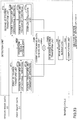
- FIGS. 17A and 17B are diagrams illustrating a processing result of the overall processing by the liquid ejection device according to the embodiment. As illustrated in an upper portion of FIG. 17A , suppose that the liquid ejection device performs image formation in order of black, cyan, magenta, and yellow. A lower portion of FIG. 17A is a plan view of the liquid ejection device when viewed from the top surface of the liquid ejection device.
- the one-cycle preceding position of the print medium is subtracted from the current position of the print medium detected by the sensor as illustrated in the lower portion of FIG. 17A , so that a change of the position of the print medium is computed.
- a difference between the position of the web 120 detected by the black sensor SENK and the position of the web 120 immediately under the black liquid ejection head unit 210K is set to "Pk”.
- a difference between the position of the web 120 detected by the cyan sensor SENC and the position of the web 120 immediately under the cyan liquid ejection head unit 210C is set to "Pc".
- a difference between the position of the web 120 detected by the magenta sensor SENM and the position of the web 120 immediately under the magenta liquid ejection head unit 210M is set to "Pm”. Further, a difference between the position of the web 120 detected by the yellow sensor SENY and the position of the web 120 immediately under the yellow liquid ejection head unit 210Y is set to "Py”.
- the image forming apparatus 110 is able to provide an increased level of accuracy of the impact position of the ejected liquid by moving each liquid ejection head unit in the orthogonal direction to compensate for the change of the position of the web 120. Further, the liquid of each color reaches the web with a good level of accuracy when performing image formation, and the color shift can be reduced and increased image quality of the image formed can be provided.
- the position where each sensor is disposed is a position which indicated by an integral multiple of a peripheral length d of the conveying roller away from the impact position.
- the black sensor SENK for explaining the position where the sensor is disposed is explained. For example, if the integral multiple of the peripheral length d is "d x 0", the black sensor SENK is disposed in a close vicinity of the impact position. If the integral multiple of the peripheral length d is "d x 1 ", the black sensor SENK is disposed at a distance ("first distance d1") from the impact position, which distance is equal to the peripheral length d of the conveying roller. In the case of "d x 1", the black sensor SENK is disposed at a position of the first distance d1 from the impact position as illustrated in FIG. 17A .
- the black sensor SENK is disposed at a distance ("second distance d2") from the impact position, which distance is obtained by doubling the peripheral length d of the conveying roller.
- the black sensor SENK is disposed at a position of the second distance d2 from the impact position as illustrated in FIG. 17A .
- the integral multiple may be 3 or greater.
- a sensor installation error, an impact position error, or a combination of these errors may be added to the distance, such as the first distance d1 and the second distance d2.
- the sensors of other colors may be disposed similarly.
- the position where each sensor is disposed is an intermediate position between the first and second rollers, the intermediate position being nearer to the first roller than the impact position.
- FIG. 18 is a diagram illustrating a position where a sensor is disposed in the liquid ejection device according to the embodiment.
- the black sensor SENK is disposed at an intermediate position between the black first roller CR1K and the black second roller CR2K, and the intermediate position is nearer to the black first roller CR1K than the black impact position PK.
- the distance of the sensor which is put closer to the black first roller CR1K from the black impact position PK may be determined based on the time needed for the control action. For instance, in this example, the distance of the sensor put closer to the black first roller CR1K is set to 20 mm. In this case, the position where the black sensor SENK is disposed is at a distance of 20 mm upstream of the black impact position PK.
- the detection error E1 becomes small. If the detection error E1 is small, the image forming apparatus 110 is able to eject the liquid of each color to the web with a good level of accuracy. Hence, when performing image formation, the image forming apparatus 110 is able to eject the liquid of each color to the web with a good level of accuracy, the color shift can be reduced and increased image quality of the formed image can be provided.
- the image forming apparatus 110 is able to eject the liquid of each color to the web with a good level of accuracy even when the distance between the liquid ejection head units is not consistent with the integral multiple of the peripheral length d of the roller.
- FIG. 19 is a diagram illustrating a hardware configuration of a first comparative example.
- the position of the web 120 is detected, before each liquid ejection head unit reaches the position where the liquid is ejected.
- the position where the sensor is disposed is 200 mm upstream from the position immediately under the liquid ejection head unit.
- the image forming apparatus of the first comparative example moves the liquid ejection head unit based on the detection result to compensate for the change of the position of the print medium.
- FIG. 20 is a diagram illustrating a processing result of overall processing performed by the liquid ejection device according to the first comparative example.
- the liquid ejection head units are disposed so that the distance between the liquid ejection head units is consistent with the integral multiple of the peripheral length d of the roller.
- a difference between the position of the web detected by each sensor and the position of the web immediately under the liquid ejection head unit is set to 0.
- FIG. 21 is a diagram illustrating a processing result of overall processing performed by a liquid ejection device according to a second comparative example.
- the second comparative example has a hardware configuration which is the same as that of the first comparative example.
- the second comparative example differs from the first comparative example in that each of the distance between the liquid ejection head units of black and cyan and the distance between the liquid ejection head units of magenta and yellow is set to 1.75d. Namely, in the second comparative example, the distance between the liquid ejection head units of black and cyan and the distance between the liquid ejection head units of magenta and yellow are not consistent with the integral multiple of the peripheral length d of the roller.
- a difference between the position of the web detected by the black sensor SENK and the position of the web immediately under the black liquid ejection head unit 210K is set to "Pk”.
- a difference between the position of the web detected by the cyan sensor SENK and the position of the web immediately under the cyan liquid ejection head unit 210C is set to "Pc”.
- a difference between the position of the web detected by the magenta sensor SENK and the position of the web 120 immediately under the magenta liquid ejection head unit 210M is set to "Pm".
- FIG. 23 is a block diagram illustrating a correlation computation method according to an embodiment.
- a detection unit having the configuration illustrated is configured to perform correlation computation so that a relative position of the web to the position of the sensor, a movement, a moving velocity, and a combination of these items are computed.
- the detection unit illustrated in FIG. 23 includes a first two-dimensional (2D) Fourier transform unit FT1, a second two-dimensional (2D) Fourier transform unit FT2, a correlation image data generation unit DMK, a peak position search unit SR, a computation unit CAL, and a transform result storage unit MEM.
- FT1 first two-dimensional (2D) Fourier transform unit
- FT2 second two-dimensional (2D) Fourier transform unit
- DMK correlation image data generation unit
- SR peak position search unit
- CAL computation unit CAL
- MEM transform result storage unit
- the first 2D Fourier transform unit FT1 is configured to transform first image data D1. Specifically, the first 2D Fourier transform unit FT1 has a configuration including a Fourier transform unit FT1a for the orthogonal direction and a Fourier transform unit FT1b for the transport direction.
- the Fourier transform unit FT1a for the orthogonal direction is configured to perform a one-dimensional Fourier transform of the first image data D1 in the orthogonal direction.
- the Fourier transform unit FT1b for the transport directions is configured to perform a one-dimensional Fourier transform of the first image data D1 in the transport direction based on the transform result obtained by the Fourier transform unit FT1a for the orthogonal direction.
- the Fourier transform unit FT1a for the orthogonal direction and the Fourier transform unit FT1b for the transport direction perform the one-dimensional Fourier transforms in the orthogonal direction and in the transport direction, respectively.
- the first 2D Fourier transform unit FT1 outputs the obtained transform results to the correlation image data generation unit DMK.
- the second 2D Fourier transform unit FT2 is configured to transform second image data D2.
- the second 2D Fourier transform unit FT2 has a configuration including a Fourier transform unit FT2a for the orthogonal direction, a Fourier transform unit FT2b for the transport direction, and a complex conjugate unit FT2c.
- the Fourier transform unit FT2a for the orthogonal direction is configured to perform a one-dimensional Fourier transform of the second image data D2 in the orthogonal direction.
- the Fourier transform unit FT2b for the transport direction is configured to perform a one-dimensional Fourier transform of the second image data D2 in the transport direction based on the transform result obtained by the Fourier transform unit FT2a for the orthogonal direction. In this way, the Fourier transform unit FT2a for the orthogonal direction and the Fourier transform unit FT2b for the transport direction perform the one-dimensional Fourier transforms in the orthogonal direction and the transport direction, respectively.
- the complex conjugate unit FT2c is configured to compute a complex conjugate of the transform results by the Fourier transform unit FT2a for the orthogonal direction and the Fourier transform unit FT2b for the transport direction.
- the second 2D Fourier transform unit FT2 is configured to output the complex conjugate computed by the complex conjugate unit FT2c to the correlation image data generation unit DMK.
- the correlation image data generation unit DMK is configured to generate correlation image data based on the transform results of the first image data D1 output from the first 2D Fourier transform unit FT1 and the transform results of the second image data D2 output from the second 2D Fourier transform unit FT2.
- the correlation image data generation unit DMK has a configuration including an integral unit DMKa and a 2D inverse Fourier transform unit DMKb.
- the integral unit DMKa is configured to compute an integral of the transform results of the first image data D1 and the transform results of the second image data D2.
- the integral unit DMKa is configured to output the computed integral to the 2D inverse Fourier transform unit DMKb.
- the 2D inverse Fourier transform unit DMKb is configured to perform a 2D inverse Fourier transform of the integral from the integral unit DMKa. After the 2D inverse Fourier transform is performed in this way, correlation image data is generated.
- the 2D inverse Fourier transform unit DMKb is configured to output the correlation image data to the peak position search unit SR.
- the peak position search unit SR is configured to determine a peak position where the luminance becomes the peak (peak value) in the correlation image data.
- the correlation image data input to the peak position search unit SR includes optical intensity values (i.e., values indicating the magnitudes of luminance).
- the values indicating the magnitudes of luminance are input in a matrix form.
- luminance values are arrayed at intervals of a pixel pitch (pixel size) of the area sensor. Hence, it is preferable to perform the peak position search after sub-pixel processing is performed.
- the peak position can be determined with a good level of accuracy.
- the detection unit is able to output the relative position, the movement, and the moving velocity with a good level of accuracy.
- the peak position search unit SR is configured to determine the peak position as follows.
- FIG. 24 is a diagram for explaining a method of determining a peak position in the correlation computation according to the embodiment.
- the horizontal axis indicates a position in the transport direction of the image indicated by the correlation image data
- the vertical axis indicates a luminance of the image indicated by the correlation image data.
- the peak position search unit SR determines a peak position P in a curve k connecting the first data value q1, the second data value q2, and the third data value q3.
- the peak position search unit SR computes a difference between two of the luminance values of the image indicated by the correlation image data.
- the peak position search unit SR extracts a combination of the data values with which the difference is the greatest among the obtained differences.
- the peak position search unit SR extracts a combination of the data values with which the difference is the second greatest among the obtained differences.
- the peak position search unit SR is able to extract three data values such as the first data value q1 and the second data value q2, and the third data value q3 as illustrated in FIG. 24 .
- the peak position search unit SR is able to determine the peak position P in the curve k.
- the peak position search unit SR is able to reduce the computation load of the sub pixel processing and determine the peak position P quickly. Note that the position of the combination of data values where the difference is the greatest corresponds to the steepest portion. Moreover, another sub pixel processing different from the above-described processing may be performed.
- FIG. 25 is a diagram illustrating an example of computation results of the correlation computation according to the embodiment.
- a correlation intensity distribution of a correlation function is illustrated in FIG. 25 .
- the X-axis and the Y-axis indicate the pixel serial numbers.
- a peak position such as a "correlation peak" as indicated in FIG. 25 is determined by the peak position search unit SR ( FIG. 23 ).
- the computation unit CAL is configured to compute a relative position, a movement, and a moving velocity of the web.
- the computation unit CAL is configured to compute a relative position and a movement of the web by computing a difference between the median position of the correlation image data and the peak position obtained by the peak position search unit SR.
- the computation unit CAL is configured to compute a moving velocity of the web by dividing a movement of the web by a time needed for the movement.
- the detection unit is able to determine the relative position, the movement, and the moving velocity by performing the correlation computation.
- the method of determining the relative position, the movement, and the moving velocity is not limited to the above example.
- the detection unit may be configured to determine the relative position, the movement, and the moving velocity as follows.
- the above-described detection unit generates binary values of luminance values of each of a first image data and a second image data. Namely, when a luminance value is less than a predetermined threshold, the detection unit converts the luminance value into "0", and when a luminance value is greater than the threshold, the detection unit converts the luminance value into "1". In this way, the binary values of the first image data and the second image data are compared with each other, and the detection unit is able to determine the relative position.
- the detection unit may be configured to determine the relative position, the movement, and the moving velocity by using another detection method other than described above. For instance, the detection unit may be configured to determine the relative position based on patterns derived from the respective image data by performing a pattern matching process.
- FIG. 26 is a block diagram illustrating a functional configuration of the liquid ejection device according to the embodiment.
- the image forming apparatus 110 includes a detection unit 11F10 for each of the plurality of liquid ejection head units.
- the image forming apparatus 110 further includes a movement unit 110F20.
- the detection units 110F10 are provided for the liquid ejection head units, respectively. Specifically, in the example of FIG. 26 , the four detection units 110F10 are provided. Each detection unit 110F10 is configured to detect a lateral position of the print medium of the web 120 in the orthogonal direction. Note that each detection unit 110F10 is implemented by the configuration illustrated in FIG. 4 .
- the movement unit 110F20 is configured to move the liquid ejection head unit based on the detection result by the detection units 110F10. Note that the movement unit 110F20 is implemented by the configuration illustrated in FIG. 14 .
- the image forming apparatus 110 further includes the conveying roller.
- the conveying roller is the conveying roller 230 illustrated in FIG. 26 .
- the conveying roller 230 is configured to transport the print medium of the web 120 in the transport direction as illustrated in FIG. 26 .
- each sensor is disposed at a distance of the integral multiple of the peripheral length d from the impact position, the change of the position of the print medium can be compensated for, and an increased level of accuracy of the impact position of the ejected liquid can be provided.
- the image forming apparatus 110 is able to correct the color shift.
- the movement unit 110F20 is configured to move the liquid ejection head units based on the detection results obtained by the detection units 110F10, and the image forming apparatus 110 is able to provide an increased level of accuracy of the impact position of the ejected liquid in the orthogonal direction.
- the position where the detection is performed by the detection unit 110F10 is the intermediate position between the rollers upstream of the impact position, such as in the black upstream section INTK2. Namely, if the detection is performed in the black upstream section INTK2, the image forming apparatus 110 is able to detect the position of the print medium in the orthogonal direction with a good level of accuracy.
- the image forming apparatus 110 includes the measurement unit 110F30 illustrated in FIG. 26 .
- the image forming apparatus 110 is able to detect a position of the print medium more reliably. For instance, suppose that a measurement device, such as an encoder, is disposed on the rotary shaft of the roller 230. The measurement unit 110F30 is configured to measure an amount of movement of the print medium by using the encoder. After the measurement result measured by the measurement unit 110F30 is further input, the image forming apparatus 110 is able to detect a position of the print medium in the transport direction more reliably.
- a measurement device such as an encoder
- the liquid ejection device is configured to detect a lateral position of the print medium in the orthogonal direction for each of the plurality of liquid ejection head units in a vicinity of the corresponding liquid ejection head unit. Subsequently, the liquid ejection device is configured to move the liquid ejection head unit based on the detection result.
- the liquid ejection device of this embodiment is able to compensate for the change of the impact position of the liquid in the orthogonal direction with a better level of accuracy than that in the cases of with the first comparative example and the second comparative example illustrated in FIG. 20 and FIG. 21 , respectively.
- the detection unit included in the liquid ejection device is disposed at a distance of an integral multiple of the peripheral length d of the conveying roller away from the impact position. Hence, the liquid ejection device of this embodiment is able to compensate for the change of the impact position of the liquid in the orthogonal direction.
- the liquid ejection device is not required to dispose each liquid ejection head unit at the distance of the integral multiple of the peripheral length of the conveying roller as in the first comparative example, and it is possible to reduce the restriction of the installation of each liquid ejection head unit. Moreover, even if the ejected liquid is the first one of the color inks, it is possible for the liquid ejection device of this embodiment to provide an increased level of accuracy of the impact position of the ejected liquid in the orthogonal direction.
- the liquid ejection device provides an increased level of accuracy of the impact position of the ejected liquid of each color and eliminates the color shift, and it is possible to increase the quality of the image when the image is formed on the print medium by the ejected liquid.
- the detection device 50 illustrated in FIG. 4 may be implemented by the following hardware.
- FIG. 27 is a diagram illustrating a first modification of the hardware configuration to implement the detection unit according to the embodiment.
- a description of the elements which are designated by the same reference numerals and the same as corresponding elements in the above-described embodiment will be omitted.
- the detection device 50 of the first modification differs from that in the previously described hardware configuration in that the detection device 50 of the first modification includes a plurality of optical systems.
- the hardware configuration of the first modification corresponds to a compound eye system and the previously described hardware configuration corresponds to a monocular system.
- each of the first light source 51A and the second light source 51B emits a laser beam to the web 120 as a detection target.
- position A the position to which the laser beam is emitted by the first light source 51A
- position B the position to which the laser beam is emitted by the second light source 51B
- Each of the first light source 51A and the second light source 51B includes a light emitting device to emit a laser beam, and a collimator lens to convert the laser beam emitted from the light emitting device into a collimated laser beam.
- Each of the first light source 51A and the second light source 51B is disposed in the position where the light source emits a laser beam in a slanting direction to the surface of the web 120.
- the detection device 50 includes an area sensor 11, a first imaging lens 12A disposed at a position which counters the "position A”, and a second imaging lens 12B disposed at a position which counters the "position B”.
- the area sensor 11 may be a sensor constructed by forming an image sensor 112 on a silicon substrate 111.
- the image sensor 112 includes an area-A 11A and an area-B 11B, and each of the two areas of the image sensor 112 is configured to capture a 2D image.
- the area sensor 11 may be implemented by any of a CCD sensor, a CMOS sensor, and a photodiode array.
- the area sensor 112 is mounted in a housing 13. Further, the first imaging lens 12A and the second imaging lens 12B are retained in a first lens mirror pipe 13A and a second lens mirror pipe 13B, respectively.
- the optical axis of the first imaging lens 12A is consistent with the center of the area-A 11A.
- the optical axis of the second imaging lens 12B is consistent with the center of the area-B 11B.
- the first imaging lens 12A focuses the incoming light on the area-A 11A and the second imaging lens 12B focuses the incoming light on the area-B 11B so that a 2D image is generated.
- FIG. 28 is a diagram illustrating a second modification of the hardware configuration to implement the detection unit according to the embodiment. In the following, differences between the hardware configuration of the detection device 50 illustrated in FIG. 28 and the configuration illustrated in FIG. 27 will be described.
- the detection device 50 illustrated in FIG. 28 differs from the detection device 50 illustrated in FIG. 27 in that the first imaging lens 12A and the second imaging lens 12B are united into an imaging lens array 12C.
- the area sensor 11 and other elements in the detection device 50 illustrated in FIG. 28 are essentially the same as the corresponding elements in the detection device 50 illustrated in FIG. 27 .
- an aperture 121 such that an image of the first imaging lens 12A and an image of the second imaging lens 12B may not interfere with each other.
- the aperture 121 is used, the focusing area of the image of the first imaging lens 12A and the focusing area of the image of the second imaging lens 12B may be restricted.
- the detection device 50 is able to generate the image for each of the position A and the position B.
- FIGS. 29A and 29B are diagrams illustrating a third modification of the hardware configuration to implement the detection unit according to the embodiment.
- the detection device 50 illustrated in FIG. 29A differs from the detection device 50 illustrated in FIG. 28 in that the area sensor 11 is replaced by a second area sensor 11'.
- the first imaging lens 12A and the second imaging lens 12B in the detection device 50 illustrated in FIG. 29A are the same as the corresponding elements illustrated in FIG. 28 .
- the second area sensor 11' has a configuration as illustrated in FIG. 29B .
- a plurality of image sensors "b" are fabricated on a wafer "a”. Subsequently, such image sensors are cut away from the wafer.
- the first image sensor 112A and the second image sensor 112B are formed on the silicon substrate 111 by using the image sensors.
- the first imaging lens 12A and the second imaging lens 12B are disposed at positions consistent with the positions of the first image sensor 112A and the second image sensor 112B.
- an aspect ratio of an image sensor i.e., the ratio of the X-axis and the Y-axis direction size of the image sensor
- an imaging format such as 1:1, 4:3, or 16:9.
- an image is captured for each of two or more points which are spaced at predetermined intervals.
- an image is captured for each of the points spaced at the predetermined intervals in the X-axis direction which is the transport direction 10 ( FIG. 2 ).
- the image sensor has the aspect ratio consistent with the imaging format.
- the first image sensor 112A and the second image sensor 112B may be formed on the silicon substrate 111.
- the use of the image sensor disposed for capturing an image with respect to the Y-axis direction may become unnecessary. Hence, the use of the unnecessary image sensor is avoided.
- the first image sensor 112A and the second image sensor 112B are formed with a good level of accuracy by the semiconductor fabrication process, and it is possible to increase the level of accuracy of the distance between the first image sensor 112A and the second image sensor 112B.
- FIG. 30 is a diagram illustrating a lens array including a plurality of imaging lenses for use in the detection unit according to the embodiment.
- the lens array illustrated in FIG. 30 may be used to implement the detection unit according to the embodiment.
- the lens array illustrated in FIG. 30 may have a structure in which the imaging lenses are integrated. Specifically, the lens array illustrated in FIG. 30 includes a total of nine imaging lenses A1 to C3 in which the imaging lenses are arrayed in three rows in a longitudinal direction and three columns in a lateral direction. If this lens array is used, an image may be captured for each of nine points spaced in the X-axis and Y-axis directions. In this case, the area sensor including imaging areas of nine points is used.
- the computations for two imaging areas may easily be performed simultaneously or by parallel execution. Subsequently, if the computation results are averaged or the error elimination is performed, the detection device is able to provide an increased level of stability of the computations or accuracy of the computation results when compared with the case in which one computation result is used. Moreover, there is a case in which computation is executed based on the application program in which the computation speed is varied. Even in such a case, the areas to which the correlation computation is applied may be increased and the velocity computation results with an increased level of accuracy may be obtained.
- FIG. 31 is a diagram illustrating a modification of the liquid ejection device according to the embodiment.
- the arrangement of the first support member and the second support member differs from that in the previously described embodiment of FIG. 2 .
- the first support member and the second support member may be implemented by a first member RL1, a second member RL2, a third member RL3, a fourth member RL4, and a fifth member RL5.
- the second support member disposed upstream of each liquid ejection head unit and the first support member disposed downstream of each liquid ejection head unit may be implemented by the common members.
- the first support member and the second support member may be implemented by a number of rollers or a number of curved boards.
- FIG. 32 is a timing chart for explaining a modification of the method of computing an amount of change of a print medium in the liquid ejection device according to the embodiment.
- the amount of change may be computed by the method as illustrated in FIG. 32 .
- the image forming apparatus of this modification is configured to compute the amount of change based on plural detection results.
- the control device CTRL is configured to output a computation result indicating the amount of change based on a first detection result S1 and a second detection result S2.
- the first detection result S1 and the second detection result S2 are detection results indicated by the sensor data output from any two sensors of the plurality of sensors.
- the amount of change is computed for each of the plurality of liquid ejection head units.
- An exemplary method of computing the amount of change using the cyan liquid ejection head unit 210C ( FIG. 2 ) will be described.
- the amount of change is computed based on both the detection result output from the cyan sensor SENC ( FIG. 2 ), and the detection result output from the black sensor SENK ( FIG. 2 ) disposed upstream of the cyan sensor SENC.
- the first detection result S1 is the detection result output from the black sensor SENK
- the second detection result S2 is the detection result output from the cyan sensor SENC.
- T2 denotes a moving time required for the print medium to be transported from the position of the black sensor SENK to the position of the cyan sensor SENC.
- T2 L2/V
- sampling frequency n T2/A.
- ⁇ X denotes the amount of change which is the computation result.
- the amount of change is computed by comparing the first detection result S1 obtained the moving time "T2" before with the second detection result S2 obtained at the detection cycle "0".
- the image forming apparatus is configured to compute an amount of change of the position of the print medium when the print medium is moved to the position of the sensor, and drive the actuator based on the computation result.
- the image forming apparatus controls the actuator and moves the cyan liquid ejection head unit 210C ( FIG. 14 ) in the orthogonal direction to compensate for the amount of change " ⁇ X".
- the image forming apparatus is able to perform image formation with an increased level of accuracy of a printed image on the print medium.
- the amount of change can be computed without accumulating the position information of the sensors. In this way, it is possible to attenuate the accumulation of detection errors of the sensors.
- the computation of the amount of change may be performed by using other liquid ejection head units likewise.
- the amount of change for the cyan liquid ejection head unit 210C ( FIG. 2 ) is computed based on the first detection result S1 output from the black sensor SENK ( FIG. 2 ) and the second detection result S2 output from the cyan sensor SENC ( FIG. 2 ).
- the amount of change for the magenta liquid ejection head unit 210M ( FIG. 2 ) is computed based on the first detection result S1 output from the cyan sensor SENC and the second detection result S2 output from the magenta sensor SENM.
- the amount of change for the yellow liquid ejection head unit 210Y ( FIG.
- the black liquid ejection head unit 210K ( FIG. 2 ) is computed based on the first detection result S1 output from the magenta sensor SENM and the second detection result S2 output from the yellow sensor SENY. Furthermore, the amount of change for the black liquid ejection head unit 210K ( FIG. 2 ) may be computed based on the second detection result S2 output from the black sensor SENK ( FIG. 2 ).
- the detection result used for the first detection result S1 is not limited to the detection result output from the sensor disposed upstream of and adjacent to the liquid ejection head unit being moved.
- the first detection result S1 may be a detection result output from any sensor disposed upstream of the liquid ejection head unit being moved.
- the amount of change for the yellow liquid ejection head units 210Y may be computed based on the first detection result S1 which is a detection result output from any one of the second sensor SEN2, the black sensor SENK, and the cyan sensor SENC.
- the second detection result S2 is a detection result output from the sensor disposed at a position nearest to the liquid ejection head unit being moved.
- the amount of change may be computed based on three or more detection results.
- the amount of change is computed based on the plural detection results, the liquid ejection head unit is moved based on the computed amount of change, and when the liquid is ejected to the web, an image is formed on the print medium.
- the liquid ejection device of the present disclosure may be implemented by a liquid ejection system including one or more liquid ejection devices.
- the liquid ejection device of the present disclosure may be implemented by a liquid ejection system including a first device having a black liquid ejection head unit 210K and a cyan liquid ejection head unit 210C mounted on a housing of the first device, and a second device having a magenta liquid ejection head unit 210M and a yellow liquid ejection head unit 210Y mounted on a housing of the second device.
- the liquid is not limited to ink but may be a recording liquid of any other kind or a fixing process liquid. Namely, the liquid ejection device and the liquid ejection system of the present disclosure may be applied to a liquid ejection device for a recording liquid of another kind different from ink.
- the liquid ejection device and the liquid ejection system of the present disclosure are not limited to image forming apparatuses.
- an object to be formed by the liquid ejection device and the liquid ejection system of the present disclosure may be a three-dimensional fabrication object.
- the medium to be transported therein is not limited to a print medium or recording medium, such as paper.
- the medium to be transported may be provided of a material with liquid adherence.
- the material with liquid adherence may be any material to which liquid adheres temporarily or permanently, such as paper, thread, fibers, cloth, leather, metal, plastics, glass, wood, ceramics, or a combination thereof.
- all or a part of the steps of the liquid ejection method may be implemented by causing a computer incorporated in an image forming apparatus, an information processing apparatus or a combination thereof to execute a program for performing the liquid ejection method.
- the liquid ejection device of the present disclosure it is possible to provide an increased level of accuracy of an impact position of ejected liquid in a direction orthogonal to a direction in which a print medium is transported.
Landscapes
- Engineering & Computer Science (AREA)
- Quality & Reliability (AREA)
- Ink Jet (AREA)
Abstract
Description
- The present disclosure relates to a liquid ejection device, a liquid ejection system, and a liquid ejection method.
- Conventionally, an inkjet image formation method is known which carries out image formation with ink ejected from a print head. Approaches for increasing the printing quality of an image printed on a print medium by this image forming method are also known.
- For example, a method for adjusting a position of a print head in order to increase the printing quality of a printed image is known as one of the approaches. Specifically, in this method, a positional change of a lateral direction of a web of print medium passing through a continuous-form printing system is first detected by a sensor, and the position of the print head in the lateral direction is adjusted to compensate for the positional change detected by the sensor. For details of this method, see Japanese Laid-Open Patent Publication No.
2015-013476 - However, in order to further increase the image quality of a printed image, it is required to increase the level of accuracy of an impact position of ejected liquid on the print medium in a direction (which direction will be referred to as "orthogonal direction") orthogonal to a direction in which the print medium is transported. In this respect, it was difficult for the related art to increase the level of accuracy of the impact position of ejected liquid on the print medium in the orthogonal direction.
- In one aspect, the present disclosure provides a liquid ejection device which provides an increased level of accuracy of the impact position of ejected liquid on the print medium in the orthogonal direction.
- In one embodiment, the present disclosure provides a liquid ejection device including: a plurality of liquid ejection head units configured to eject liquid to a print medium at different positions on a transport path respectively; a conveying roller configured to transport the print medium on the transport path; a detection unit disposed at a distance of an integral multiple of a peripheral length of the conveying roller away from an impact position where the liquid ejected from each of the plurality of liquid ejection head units reaches the print medium, the detection unit being configured to output a detection result indicating a lateral position of the print medium in a direction orthogonal to a transport direction in which the print medium is transported; and a movement unit configured to move the corresponding one of the plurality of liquid ejection head units based on the detection result from the detection unit.
-
-
FIG. 1 is a diagram illustrating a liquid ejection device according to an embodiment. -
FIG. 2 is a diagram illustrating an overall configuration of the liquid ejection device according to the embodiment. -
FIGS. 3A and 3B are diagrams illustrating an outer configuration of a liquid ejection head unit according to an embodiment. -
FIG. 4 is a block diagram illustrating a hardware configuration to implement a detection unit according to an embodiment. -
FIG. 5 is a diagram illustrating an outer configuration of a detection device according to an embodiment. -
FIG. 6 is a block diagram illustrating a functional configuration of the detection unit according to the embodiment. -
FIGS. 7A and 7B are diagrams illustrating an example in which a lateral position of a print medium in an orthogonal direction is changed. -
FIG. 8 is a diagram for explaining the cause of color shift on the print medium. -
FIG. 9 is a block diagram illustrating a hardware configuration of a control unit according to an embodiment. -
FIG. 10 is a block diagram illustrating a hardware configuration of a data management unit included in the control unit according to the embodiment. -
FIG. 11 is a block diagram illustrating a hardware configuration of an image outputting device included in the control unit according to the embodiment. -
FIG. 12 is a flowchart for explaining overall processing performed by the liquid ejection device according to the embodiment. -
FIG. 13 is a block diagram illustrating a hardware configuration for moving the liquid ejection head unit included in the liquid ejection device according to the embodiment. -
FIG. 14 is a diagram illustrating a movement mechanism for moving the liquid ejection head unit included in the liquid ejection device according to the embodiment. -
FIG. 15 is a timing chart for explaining a method of computing a change of the position of the print medium by the liquid ejection device according to the embodiment. -
FIG. 16 is a diagram illustrating a test pattern which is used by the liquid ejection device according to the embodiment. -
FIGS. 17A and17B are diagrams illustrating a processing result of overall processing by the liquid ejection device according to the embodiment. -
FIG. 18 is a diagram illustrating a position where a sensor is disposed in the liquid ejection device according to the embodiment. -
FIG. 19 is a diagram illustrating a hardware configuration of a first comparative example. -
FIG. 20 is a diagram illustrating a processing result of overall processing performed by a liquid ejection device according to the first comparative example. -
FIG. 21 is a diagram illustrating a processing result of overall processing performed by a liquid ejection device according to a second comparative example. -
FIG. 22 is a diagram illustrating a position where a sensor is disposed in a liquid ejection device according to a comparative example. -
FIG. 23 is a diagram for explaining a correlation computation method according to an embodiment. -
FIG. 24 is a diagram for explaining a method of determining a peak position in the correlation computation according to the embodiment. -
FIG. 25 is a diagram illustrating an example of computation results of the correlation computation according to the embodiment. -
FIG. 26 is a block diagram illustrating a functional configuration of the liquid ejection device according to the embodiment. -
FIG. 27 is a diagram illustrating a first modification of the hardware configuration to implement the detection unit according to the embodiment. -
FIG. 28 is a diagram illustrating a second modification of the hardware configuration to implement the detection unit according to the embodiment. -
FIGS. 29A and 29B are diagrams illustrating a third modification of the hardware configuration to implement the detection unit according to the embodiment. -
FIG. 30 is a diagram illustrating a lens array including a plurality of imaging lenses for use in the detection unit according to the embodiment. -
FIG. 31 is a diagram illustrating a modification of the liquid ejection device according to the embodiment. -
FIG. 32 is a timing chart for explaining a modification of the method of computing an amount of change of a lateral position of a print medium in the liquid ejection device according to the embodiment. - Some embodiments of the present disclosure are now described, by way of examples only, and with reference to the accompanying drawings. The same reference number or character represents the same element or the same type of element on all the drawings, and redundant overlapping description will be omitted.
-
FIG. 1 is a diagram illustrating a liquid ejection device according to an embodiment. For example, the liquid ejection device is animage forming apparatus 110 as illustrated inFIG. 1 . In thisimage forming apparatus 110, liquid being ejected is a marking liquid, such as aqueous inks or oil-based paints. In the following, theimage forming apparatus 110 which is an example of the liquid ejection device according to the embodiment will be described. - For example, a medium being transported in the
image forming apparatus 110 is aweb 120 of continuous-form print medium. As illustrated inFIG. 1 , theweb 120 is transported byrollers 130, and theimage forming apparatus 110 ejects liquid to theweb 120 to perform image formation on theweb 120. Theweb 120 may be a continuous-form print medium or the like. Namely, theweb 120 may be a rolled-form sheet of paper and such a sheet can be rolled. Theimage forming apparatus 110 may be a production printer.
In this example, theweb 120 is transported in a direction indicated by thearrow 10 inFIG. 1 and therollers 130 position and tension theweb 120 as theweb 120 travels through theimage forming apparatus 110. Thedirection 10 will be referred to as "transport direction". Further, in this example, a direction indicated by thearrow 20 inFIG. 1 , which is orthogonal to thetransport direction 10, will be referred to as "orthogonal direction". Moreover, in this example, theimage forming apparatus 110 may comprise an inkjet printer which ejects color inks, such as yellow (Y), magenta (M), cyan (C), and black (K) inks, so that an image is formed at a predetermined position on theweb 120. -
FIG. 2 is a diagram illustrating an overall configuration of the liquid ejection device according to the embodiment. As illustrated inFIG. 2 , theimage forming apparatus 110 includes four liquidejection head units - Each of the four liquid ejection head units is configured to eject a corresponding one of the color inks to the
web 120 which is transported in thetransport direction 10. Specifically, theweb 120 is transported by using two pairs of nip rollers NR1, NR2, and aroller 230. In the following, one of the two nip roller pairs disposed upstream of the four liquid ejection head units will be referred to as "first nip rollers NR1", and the other nip roller pair disposed downstream of the first nip rollers NR1 and the four liquid ejection head units will be referred to as "second nip rollers NR2". Note that each nip roller pair pinches the print medium such as theweb 120 between the nip rollers so that the print medium is rotated in the transport direction as illustrated inFIG. 2 . In this way, the nip roller pairs and theroller 230 constitute a mechanism configured to transport theweb 120 in the transport direction. - It is preferable that the print medium of the
web 120 is a continuous-form sheet extending longitudinally in the transport direction. Specifically, it is preferable that a length of the print medium is greater than a distance between the first nip rollers NR1 and the second nip rollers NR2. Furthermore, the print medium is not limited to the web. Namely, the print medium may be fanfold paper (e.g., z-fold paper). - In the configuration illustrated in
FIG. 2 , the four liquid ejection head units are disposed in order of black (K), cyan (C), magenta (M), and yellow (Y) in the direction from the upstream side to the downstream side. Specifically, the liquid ejection head unit disposed on the most upstream side is the black liquidejection head unit 210K. The liquid ejection head unit disposed on the second most upstream side is the cyan liquidejection head unit 210C. The liquid ejection head unit disposed on the second most downstream side is the magentaliquid ejection head 210M. The liquid ejection head unit disposed on the most downstream side is the yellow liquidejection head unit 210Y. - Each of the four liquid ejection head units is configured to eject the corresponding one of the color inks to a predetermined position on the
web 120 in accordance with image data. This position where the liquid ejected from each liquid ejection head unit reaches the print medium of the web 120 (which position will be referred to as "impact position") is located immediately under the liquid ejection head unit concerned. In this example, the black ink is ejected to an impact position of the black liquidejection head unit 210K ("black impact position PK"), the cyan ink is ejected to an impact position of the cyan liquidejection head unit 210C ("cyan impact position PC"), the magenta ink is ejected to an impact position of the magenta liquidejection head unit 210M ("magenta impact position PM"), and the yellow ink is ejected to an impact position of the yellow liquidejection head unit 210Y ("yellow impact position PY"). Note that the timing when each liquid ejection head unit ejects the ink is controlled by acontroller 520 connected to the liquid ejection head unit. - It is preferable that, in the
image forming apparatus 110, a plurality of rollers are provided for each of the four liquid ejection head units. Specifically, it is preferable that, as illustrated inFIG. 2 , the plurality of rollers are disposed at both positions upstream and downstream of each liquid ejection head unit. In the illustrated example, a roller ("first roller") is disposed in each liquid ejection head unit upstream of the liquid ejection head unit to transport theweb 120 to the impact position, and a roller ("second roller") is disposed downstream of each liquid ejection head unit to transport theweb 120 from the impact position to a downstream position. In this way, by disposing the first rollers and the second rollers, it is possible to prevent rattling of theweb 120 at each impact position during the rotation of theweb 120. Note that the first rollers and the second rollers are used to transport the print medium, and these rollers may be driven rollers. Alternatively, the first rollers and the second rollers may be rollers rotated by a motor. - However, it is not necessary that the first rollers which implement the first support member and the second rollers which implement the second support member are rollers, such as driven rollers. Namely, the first rollers and the second rollers may be support members configured to support the print medium. For example, the first support member and the second support member may be implemented by pipes or shafts having a round cross section. Otherwise, the first support member and the second support member may be implemented by curved plates having a circular portion which comes in contact with the print medium. An example in which the first support member and the second support member are disposed is explained. Specifically, an example in which the first support member is implemented by the first rollers and the second support member is implemented by the second rollers is explained.
- In the illustrated example, a black first roller CR1K for transporting the
web 120 to the black impact position PK is disposed in order to eject the black ink to the predetermined position on theweb 120. A black second roller CR2K for transporting theweb 120 from the black impact position PK to the downstream position is disposed. Similarly, a cyan first roller CR1C and a cyan second roller CR2C are disposed with respect to the cyan liquidejection head unit 210C. Furthermore, a magenta first roller CR1M and a magenta second roller CR2M are disposed with respect to the magenta liquidejection head unit 210M. Moreover, a yellow first roller CR1Y and a yellow second roller CR2Y are disposed with respect to the yellow liquidejection head unit 210Y. -
FIGS. 3A and 3B are diagrams illustrating an outer configuration of a liquid ejection head unit according to an embodiment.FIG. 3A is a plan view illustrating an example of the four liquidejection head units 210K to 210Y of theimage forming apparatus 110 according to the embodiment. - As illustrated in
FIG. 3A , each liquidejection head unit 210 is a line-type liquid ejection head unit. Namely, in theimage forming apparatus 110, the four liquidejection head units transport direction 10 of the print medium. - For instance, in the black liquid
ejection head unit 210K, fourblack heads 210K-1, 210K-2, 210K-3, and 210K-4 are disposed in a zig-zag pattern in the direction orthogonal to thetransport direction 10 of theweb 120. Thereby, theimage forming apparatus 110 is able to form an image that covers an overall width direction of an image formation area (printing area) of the web 120 (which direction corresponds to the orthogonal direction which is orthogonal to the transport direction). Note that the configurations of other liquidejection head units ejection head unit 210K, and a description thereof will be omitted. - Although the example of the liquid ejection head unit including the four heads has been illustrated, a liquid ejection head unit including a single head may be utilized instead of the above example.
- A sensor configured to detect a lateral position of the print medium in the orthogonal direction (which is an example of a detection unit) is disposed for each of the liquid ejection head units. Examples of this sensor include an optical sensor utilizing light, such as infrared light, a laser sensor, an air pressure sensor, an optoelectronic sensor, a supersonic wave sensor, etc. For example, the optical sensor may be implemented by a charge-coupled-device (CCD) camera. The sensor to implement the detection unit may be a sensor configured to detect an edge of the print medium. For instance, the detection unit may be implemented by the following hardware configuration.
-
FIG. 4 is a block diagram illustrating a hardware configuration to implement a detection unit according to an embodiment. For instance, the detection unit may be implemented by the hardware configuration illustrated inFIG. 4 , which includes adetection device 50, acontrol device 52, amemory device 53, and acomputation device 54. - Next, the
detection device 50 is explained.FIG. 5 is a diagram illustrating an outer configuration of a detection device according to an embodiment. - When a position of a target, such as the web, is detected by the detection device illustrated in
FIG. 5 , light from a light source is emitted to the web of print medium and a speckle pattern image generated by the reflected light is captured by an imaging sensor. Specifically, the detection device includes a semiconductor laser light source (LD) and a collimator lens (CL). The detection device further includes a CMOS (complementary metal oxide semiconductor) image sensor configured to capture a speckle pattern image, and a telecentric imaging optical system (OL) configured to focus the speckle pattern image onto the CMOS image sensor. - In the configuration illustrated in
FIG. 5 , the CMOS image sensor captures a speckle pattern image at each of multiple times including time T1 and time T2. The computation device, such as an FPGA (field-programmable gate array) circuit, is configured to perform correlation computation based on the speckle pattern image captured at time T1 and the speckle pattern image captured at time T2. Based on the movement of the position of the correlation peak obtained from the computation result from the computation device, the CMOS image sensor outputs an amount of movement of the print medium in a period from time T1 to time T2. Note that, in the illustrated example, the dimensions (width W x depth D x height H) of the detection device are 15 x 60 x 32 mm. The details of the correlation computation will be described later. - Note that the CMOS image sensor is an example of the imaging unit and the FPGA circuit is an example of the computation device.
- As illustrated in
FIG. 4 , thecontrol device 52 is configured to control thedetection device 50. Specifically, thecontrol device 52 outputs a trigger signal to thedetection device 50 and controls the timing at which the shutter of the CMOS image sensor is caused to fire. Thecontrol device 52 is configured to control thedetection device 50 and receive a two-dimensional image from thedetection device 50. Further, thecontrol device 52 is configured to send the two-dimensional image generated by thedetection device 50 to thememory device 53. - The
memory device 53 is implemented by a memory. Note that it is desirable that thecontrol device 52 is configured to divide the two-dimensional image received from thedetection device 50 into image portions and store the image portions in different storage areas. - The
computation device 54 is implemented by a microcomputer. Namely, thecomputation device 54 is configured to perform computation using the image data stored in thememory device 53 in order to carry out various processes. - For example, the
control device 52 and thecomputation device 54 are implemented by a CPU (central processing unit) or electronic circuitry. Note that thecontrol device 52, thememory device 53, and thecomputation device 54 may not be separate devices. For example, thecontrol device 52 and thecomputation device 54 may be implemented by a single CPU. -
FIG. 6 is a block diagram illustrating a functional configuration of a detection unit according to an embodiment. As illustrated inFIG. 6 , the detection unit includes an imaging unit 110F1, an imaging control unit 110F2, a memory unit 110F3, and a velocity computation unit 110F4. - In the following, a case in which an image of the
web 120 transported in thetransport direction 10 is captured by the imaging unit 110F1 twice (namely, two images are generated by the imaging unit 110F1) is explained. A position where the first one of the images is captured by the imaging unit 110F1 is referred to as position A, and a position where the second one of the images is captured by the imaging unit 110F1 is referred to as position B. Suppose that, when the second image is captured, the first image captured at position A is already moved to position B by the transport of the web in thetransport direction 10. - As illustrated in
FIG. 6 , the imaging unit 110F1 is configured to capture an image of theweb 120 transported in thetransport direction 10. For example, the imaging unit 110F1 is implemented by the detection unit 50 (FIG. 4 ). - The imaging control unit 110F2 includes an image acquisition unit 110F21 and a shutter control unit 110F22. For example, the imaging control unit 110F2 is implemented by the control device 52 (
FIG. 4 ). - The image acquisition unit 110F21 is configured to acquire the image captured by the imaging unit 110F1. The shutter control unit 110F22 is configured to control the timing at which the image is captured by the imaging unit 110F1.
- The memory unit 110F3 includes a first storage area 110F31, a second storage area 110F32, and an image division unit 110F33. For example, the memory unit 110F3 is implemented by the memory device 53 (
FIG. 4 ). - The image division unit 110F33 is configured to divide the image captured by the imaging unit 110F1 into an image portion indicating position A and an image portion indicating position B. Subsequently, the divided image portions are stored in the first storage area 110F31 and in the second storage area 110F32, respectively.
- The velocity computation unit 110F4 is configured to compute each of a position of the pattern on the
web 120, a moving velocity at which theweb 120 is transported, and a movement by which theweb 120 is transported, based on the image portions stored in the first storage area 110F31 and the second storage area 110F32. Moreover, the velocity computation unit 110F4 is configured to output data of a difference Δt, which indicates a shutter timing, to the shutter control unit 110F22. Namely, the velocity computation unit 110F4 outputs a trigger signal to the shutter control unit 110F22, so that the image portion indicating position A and the image portion indicating position B may be captured with the difference Δt. The velocity computation unit 110F4 may be configured to control the motor which transports theweb 120 at a velocity consistent with the computed moving velocity. For example, the velocity computation unit 110F4 is implemented by the computation unit 54 (FIG. 4 ). - The
web 120 is implemented by a member having scattering characteristic on an external surface or an internal surface of the member. When a laser beam is emitted to theweb 120, diffused reflection occurs with the reflected laser beam. A pattern is formed on theweb 120 by this diffused reflection. This pattern is a speckle pattern including spots or speckles. Hence, when the image of theweb 120 is captured, a speckle pattern image indicating the speckle pattern is captured. Because the position where a speckle pattern is present is known from this speckle pattern image, the detection unit is configured to detect where the predetermined position of theweb 120 is. Note that the laser beam which is emitted to theweb 120 is interfered with by projections and depressions formed on the external or internal surface of theweb 120, and this pattern is generated by the interference of the laser beam. - The light source is not limited to a device to emit a laser beam. For example, the light source may be implemented by a LED (light emitting diode) or an organic EL (electro-luminescence). The pattern may not be a speckle pattern depending on the type of the light source. In the following, a case in which the pattern is a speckle pattern is explained.
- When the
web 120 is transported, the speckle pattern on theweb 120 is also transported together with theweb 120. Hence, a movement of the pattern on theweb 120 may be computed by detecting the same speckle pattern at different times. After the same speckle pattern is detected and the movement of the pattern is computed, the velocity computation unit 110F4 is able to compute the movement of theweb 120. Further, if the computed movement is converted into a movement per unit time, the velocity computation unit 110F4 is able to compute the moving velocity at which theweb 120 is transported. - As described above, the imaging of the
web 120 is performed multiple times at the positions including position A and position B as illustrated. The same speckle pattern is included in each captured image. The position, the movement, and the moving velocity of the web are computed based on the speckle pattern of each captured image. In this way, based on the speckle pattern, theimage forming apparatus 110 is able to determine the detection result indicating the position of theweb 120 in the orthogonal direction. - Note that the detection unit may detect a position of the print medium in the transport direction. Namely, the detection unit may be used in common to detect a position of the print medium in the transport direction and in the orthogonal direction. This will reduce the cost for installing the detection device with respect to each of the transport direction and the orthogonal direction. Further, the number of detection devices may be reduced, which will allow saving of the installation space.
- Referring back to
FIG. 2 , in the following, the sensor disposed on the black liquidejection head unit 210K will be referred to as "black sensor SENK". Similarly, the sensor disposed on the cyan liquidejection head unit 210C will be referred to as "cyan sensor SENK". Similarly, the sensor disposed on the magenta liquidejection head unit 210M will be referred to as "magenta sensor SENK". Furthermore, the sensor disposed on the yellow liquidejection head unit 210Y will be referred to as "yellow sensor SENY". In the following, the black sensor SENK, the cyan sensor SENK, the magenta sensor SENK, and the yellow sensor SENY will collectively be called "sensor". - Moreover, in the following, the position where the sensor is disposed is the same as the position where the detection is performed. Hence, it is not necessary that all the devices including the detection device be disposed at the positions where the sensors are disposed, and devices other than the sensors which are connected together by a cable or the like may be disposed at other positions. Note that the black sensor SENK, the cyan sensor SENK, the magenta sensor SENK, and the yellow sensor SENY, illustrated in
FIG. 2 , represent an example of the positions where the sensors are disposed. - It is preferable that the position where the sensor is disposed is a position in a vicinity of each impact position. If the sensor is disposed in a vicinity of each impact position, the distance between each impact position and the sensor becomes small. If the distance between each impact position and the sensor becomes small, it is possible to reduce the error in the detection result. Hence, the
image forming apparatus 110 is able to detect the position of the print medium in the orthogonal direction by using the sensor with a good level of accuracy. - Specifically, the position in a vicinity of each impact position is a position between the first roller and the second roller. In the illustrated example, it is preferable that the position where the black sensor SENK is disposed is in a range INTK1 between the black first and second rollers CR1K and CR2K. Similarly, it is preferable that the position where the cyan sensor SENK is disposed is in a range INTC1 between the cyan first and second rollers CR1C and CR2C. Similarly, it is preferable that the position where the magenta sensor SENK is disposed is in a range INTM1 between the magenta first and second rollers CR1M and CR2M. Furthermore, it is preferable that the position where the yellow sensor SENY is disposed is in a range INTY1 between the yellow first and second rollers CR1Y and CR2Y.
- If the sensors are disposed between the first and second rollers, the sensors are able to detect the position of the print medium in the vicinity of each impact position. Moreover, in many cases, the moving velocity of the print medium between the rollers is comparatively stable. Hence, the
image forming apparatus 110 is able to detect the position of the print medium in the orthogonal direction with a good level of accuracy. - It is preferable that the position where the sensor is disposed is an intermediate position between the first and second rollers, the intermediate position being nearer to the first roller than the impact position. Namely, it is preferable that the sensor is disposed at a position upstream of the impact position.
- Specifically, it is preferable that the position where the black sensor SENK is disposed is in a section (which is called "black upstream section INTK2") between the black impact position PK and the position where the black first roller CR1K is disposed. Similarly, it is preferable that the position where the cyan sensor SENK is disposed is in a section (which is called "cyan upstream section INTC2") between the cyan impact position PC and the position where the cyan first roller CR1C is disposed. Similarly, it is preferable that the position where the magenta sensor SENK is disposed is in a section (which is called "magenta upstream section INTM2") between the magenta impact position PM and the position where the magenta first roller CR1M is disposed. Further, it is preferable that the position where the yellow sensor SENY is disposed is in a section (which is called "yellow upstream section INTY2") between the yellow impact position PY and the position where the yellow first roller CR1Y is disposed.
- If the above sensors are disposed in the black upstream section INTK2, the cyan upstream section INTC2, the magenta upstream section INTM2, and the yellow upstream section INTY2, respectively, the
image forming apparatus 110 is able to detect the position of the print medium in the orthogonal direction with a good level of accuracy. - Furthermore, if the above sensors are disposed in this way, the position where each sensor is disposed is located upstream of each impact position. Hence, the
image forming apparatus 110 is able to detect the position of the print medium in the orthogonal direction with a good level of accuracy by using the upstream-side sensors, and also able to compute the timing for controlling each liquid ejection head unit to eject the ink. Namely, if the web 12 is transported to the downstream position during the period when the computation is performed, each liquid ejection head unit can be controlled to eject the ink to the web 12 according to the computed timing. - If each sensor is disposed at a position immediately under the corresponding liquid ejection head unit, a color shift may arise due to the delay of the control action. Hence, if each sensor is disposed upstream of the corresponding impact position in order to prevent the color shift, the
image forming apparatus 110 is able to provide increased image quality. If each sensor is disposed in a vicinity of the corresponding impact position, the restriction of the installation space for the sensor may arise. Hence, it is preferable that the position where each sensor is disposed is in a section between the corresponding impact position and the corresponding first roller. -
FIGS. 7A and 7B are diagrams illustrating an example in which a lateral position of the print medium in the orthogonal direction is changed. In the this example, suppose that the web 120 (the print medium) is transported in thetransport direction 10 as illustrated inFIG. 7A . When theweb 120 is transported by the conveying roller, there may be a case in which the position of theweb 120 in the orthogonal direction perpendicular to thetransport direction 10 is changed as illustrated inFIG. 7B . Namely, theweb 120 in this example is snaking along the transport path as illustrated inFIG. 7B . - For example, the change of the position of the
web 120 in the orthogonal direction (or snaking movement) may arise due to eccentricity or misalignment of the conveying roller or cutting of theweb 120 by the blade. Moreover, when theweb 120 has a too small width in the orthogonal direction, thermal expansion of the conveying roller or the like may affect the change of the position of theweb 120 in the orthogonal direction. -
FIG. 8 is a diagram for explaining the cause of color shift on the print medium. When the position of the web 120 (the print medium) in the orthogonal direction is changed (or when the snaking movement arises) as illustrated inFIG. 7B , color shift is likely to arise on theweb 120 due to the cause illustrated inFIG. 8 . - Specifically, when an image is formed on the print medium using multiple color inks (or when a color image is formed), in the image forming apparatus, the color inks ejected from the liquid ejection head units are overlapped to form a color image on the
web 120 as illustrated inFIG. 8 . - There may be the case in which the change of the position of the web 120 (or the snaking movement) illustrated in
FIG. 7B arises with respect to areference line 320 indicated inFIG. 8 . In this case, the position of theweb 120 in the orthogonal direction is changed due to the snaking movement of theweb 120 relative to the liquid ejection head units, and if each liquid ejection head unit ejects the ink to theweb 120 at the same lateral position, the color shift arises on theweb 120 as indicated bylines 330 inFIG. 8 . Namely, the positions of the lines formed on theweb 120 with the inks ejected from the liquid ejection head units shift in the orthogonal direction, and thecolor shift 330 is caused. If thecolor shift 330 arises, the image quality of the image formed on theweb 120 will deteriorate. - A hardware configuration of a
controller 520 illustrated inFIG. 2 which is an example of a control unit according to an embodiment will be described. -
FIG. 9 is a block diagram illustrating a hardware configuration of the control unit (the controller 520). As illustrated inFIG. 9 , thecontroller 520 includes ahost device 71 which is an information processing apparatus, and aprinter 72. In this embodiment, thecontroller 520 is configured to control theprinter 72 to perform image formation to form an image on the print medium based on image data and control data received from thehost device 71. - For example, the
host device 71 is implemented by a personal computer (PC). Theprinter 72 includes a printer controller 72C and aprinter engine 72E. - The printer controller 72C is configured to control operation of the
printer engine 72E. Initially, the printer controller 72C transmits a print request to thehost device 71 and receives control data from thehost device 71 via a control line 70LC. Further, the printer controller 72C transmits and receives the control data to and from theprinter engine 72E via control lines 72LC. Various printing conditions indicated by the control data are input to the printer controller 72C through the communication of the control data with theprinter engine 72E, and the printing conditions are stored in registers of the printer controller 72C. Subsequently, the printer controller 72C controls theprinter engine 72E based on the control data, and performs image formation according to the control data (i.e., print job data). - The printer controller 72C includes a CPU 72Cp, a print control device 72Cc, and a memory device 72Cm. Note that the CPU 72Cp and the print control device 72Cc are interconnected by a bus 72Cb to communicate with each other. The bus 72Cb is connected to the control line 70LC via a communication interface (IF).
- The CPU 72Cp is configured to control the overall operation of the
printer 72 by executing a control program stored in the memory device 72Cm. Namely, the CPU 72Cp is provided to implement the computation device and the control device (FIG. 4 ). - The print control device 72Cc is configured to transmit and receive commands and status data to and from the
printer engine 72E based on the control data received from thehost device 71. Thereby, the print control device 72Cc controls theprinter engine 72E. The memory unit 110F3 ofFIG. 6 may be implemented by the memory device 72Cm. The velocity computation unit 110F4 ofFIG. 6 may be implemented by the CPU 72Cp. Note that the functions of the memory unit 110F3 and the velocity computation unit 110F4 may be implemented by another computation unit and another memory unit. - The
host device 71 and theprinter engine 72E are interconnected by four data lines 70LD-C, 70LD-M, 70LD-Y, and 70LD-K (or a plurality of data lines). Theprinter engine 72E receives image data from thehost device 71 via these data lines. Subsequently, theprinter engine 72E performs image formation of each color on the print medium under the control of the printer controller 72C. - The
printer engine 72E includes four data management devices 72EC, 72EM, 72EY, and 72EK (or a plurality of data management devices), an image output device 72Ei, and a transport control device 72Ec, which will be described below. -
FIG. 10 is a block diagram illustrating a hardware configuration of the data management device included in the control unit according to the embodiment. For example, each of the plurality of data management devices has the same configuration. Since these data management units in this example have the same configuration, a description will be given of the configuration of the data management device 72EC as a typical one, and a description of other data management units is omitted. - As illustrated in
FIG. 10 , the data management device 72EC includes a logic circuit 72EC1 and a memory device 72ECm. The logic circuit 72EC1 is connected to thehost device 71 via the data line 70LD-C. Further, the logic circuit 72EC1 is connected to the print control device 72Cc via the control line 72LC. Note that the logic circuit 72EC1 may be implemented by an ASIC (application specific integrated circuit) or a PLD (programmable logic device). - The logic circuit 72EC1 is configured to store the image data received from the
host device 71 into the memory device 72ECm based on the control signal received from the printer controller 72C (FIG. 9 ). - The logic circuit 72EC1 is configured to read the cyan image data Ic from the memory device 72ECm based on the control signal received from the printer controller 72C. Subsequently, the logic circuit 72EC1 is configured to send the read cyan image data Ic to the image output device 72Ei.
- It is preferable that the memory device 72ECm has a storage capacity to store image data amounting to 3 pages. With the storage capacity of 3-page image data, the memory device 72ECm can store simultaneously image data received from the
host device 71, image data for forming an image in the current cycle, and image data for forming an image in the following cycle. -
FIG. 11 is a block diagram illustrating a hardware configuration of the image output device included in the control unit according to the embodiment. As illustrated inFIG. 11 , the image output device 72Ei includes an output control device 72Eic, and includes the cyan liquidejection head unit 210C, the magenta liquidejection head unit 210M, the yellow liquidejection head unit 210Y, and the black liquidejection head unit 210K, which are the plurality of liquid ejection head units of the color inks connected to the output control device 72Eic. - The output control device 72Eic is configured to output the image data of each of the color inks to the corresponding one of the liquid ejection head units of the color inks. Namely, the output control device 72Eic is configured to control the corresponding one of the liquid ejection head units of the color inks based on the received image data.
- The output control device 72Eic is configured to control simultaneously or individually the plurality of liquid ejection head units. Namely, the output control device 72Eic receives an input timing signal and performs control for changing the timings to cause the liquid ejection head units to eject the respective inks in response to receiving the input timing signal. Note that the output control device 72Eic may be configured to control any one of the liquid ejection head units in response to receiving a control signal from the printer controller 72C (
FIG. 9 ). Alternatively, the output control device 72Eic may be configured to control any one of the liquid ejection head units in response to receiving instructions from the user. - Note that, in the example of the
printer 72 illustrated inFIG. 9 , the path for inputting image data from thehost device 71 and the path for communication between thehost device 71 and theprinter 72 based on the control data are separate from each other. - Alternatively, the
printer 72 may be configured to perform monochrome image formation with black ink only. For example, in order to increase the image formation speed in the case of the monochrome image formation, theprinter 72 may be modified to include one data management unit and four black liquid ejection head units. In such a case, each of the black liquid ejection head units is configured to eject the black ink to the print medium. Hence, the image formation speed of the configuration of the four black liquid ejection head units may be increased from that of the configuration including only one black liquid ejection head unit. - The transport control device 72Ec (
FIG. 9 ) is implemented by a combination of an actuator, a mechanism, and a driver device which are configured to transport theweb 120 in the transport direction. For instance, the transport control device 72Ec is configured to control the motors engaged with the rollers to transport theweb 120 in the transport direction. -
FIG. 12 is a flowchart for explaining overall processing by the liquid ejection device according to the embodiment. For example, suppose that image data indicating an image to be formed on the web 120 (FIG. 1 ) is initially input to theimage forming apparatus 110. Subsequently, theimage forming apparatus 110 performs the overall processing illustrated inFIG. 12 based on the image data, so that an image indicated by the image data is formed on theweb 120. - Note that the processing of
FIG. 12 is provided for one liquid ejection head unit. Namely,FIG. 12 illustrates the processing related to the black liquidejection head unit 210K (FIG. 2 ). The processing related to other liquid ejection head units may be performed separately in parallel with, prior to or subsequent to the processing ofFIG. 12 . - As illustrated in
FIG. 12 , in step S01, theimage forming apparatus 110 detects a lateral position of the print medium in the orthogonal direction. Namely, in step S01, theimage forming apparatus 110 detects the lateral position of theweb 120 in the orthogonal direction by using the sensor SENK. - In step S02, the
image forming apparatus 110 moves the liquidejection head unit 210K in the orthogonal direction (perpendicular to the transport direction of the web 120) based on the detection result obtained at step S01. In this step S02, the liquidejection head unit 210K is moved to compensate for the change of the position of theweb 120 indicated by the detection result obtained at step S01. For instance, in step S02, theimage forming apparatus 110 moves the liquidejection head unit 210K in the orthogonal direction and compensates for the change of the orthogonal-direction position of theweb 120 detected at step S01. -
FIG. 13 is a block diagram illustrating a hardware configuration for moving the liquid ejection head unit included in the liquid ejection device according to the embodiment. For example, theimage forming apparatus 110 includes the sensor (SENK, SENC, SENM, SENY), atime shifting device 81, acomputation device 82, an LPF (low pass filter) 83, and anactuator controller 84. - The
time shifting device 81 is configured to store the detection result from the sensor and store data indicating a one-cycle preceding position of the print medium. Namely, thetime shifting device 81 is implemented by a memory device. - The
computation device 82 is configured to subtract, from the current position of the print medium detected by the sensor, the one-cycle preceding position of the print medium stored in thetime shifting device 81 to compute the change of the position of the print medium. Namely, thecomputation device 82 computes an amount of snaking movement. Thecomputation device 82 is implemented by a processor (CPU) or an electronic circuit. - The
LPF 83 is configured to perform a filtering process on the amount of snaking movement computed by thecomputation device 82. Hence, theLPF 83 reduces steep changes of the amount of snaking movement. A range of the frequency of snaking movement may be determined to some extent depending on the moving velocity of the print medium. Hence, theLPF 83 is configured to attenuate high frequency values (i.e., steep changes) based on a predetermined frequency of snaking movement. In many cases, the steep changes arise due to noise or erroneous detection. If the steep changes of the amount of snaking movement are reduced by theLPF 83, theimage forming apparatus 110 is able to reduce malfunction of the actuator. - The
actuator controller 84 is configured to control the actuator for moving the liquid ejection head unit. A configuration of the actuator (movement mechanism) controlled by theactuator controller 84 will be described below. -
FIG. 14 is a diagram illustrating a movement mechanism for moving the liquid ejection head unit included in the liquid ejection device according to the embodiment. For instance, theactuator controller 84 ofFIG. 13 corresponds to the actuator controller CTL ofFIG. 14 , and the actuator controller CTL is configured to control the actuator ACT (movement mechanism) for moving the cyan liquidejection head unit 210C as illustrated inFIG. 14 . - In the example illustrated in
FIG. 14 , the actuator ACT may be implemented by a linear actuator or a motor, and this actuator ACT is disposed on and configured to move the cyan liquidejection head unit 210C in theorthogonal direction 20. The actuator controller CTL is connected to the actuator ACT and configured to control operation of the actuator ACT - The actuator ACT may include a control circuit, a power supply circuit, and mechanical parts.
- The actuator controller CTL may be implemented by a driver circuit. The actuator controller CTL is configured to control the position of the cyan liquid
ejection head unit 210C. - The detection result obtained at the step S01 of
FIG. 12 is input to the actuator controller CTL. In the step S02 ofFIG. 12 , the actuator controller CTL controls the actuator ACT to move the liquidejection head unit 210C in theorthogonal direction 20 and compensates for the change of the orthogonal-direction position of theweb 120 detected at step S01. - In the example illustrated in
FIG. 14 , the detection result corresponds to the difference Δt described above. Hence, in this example, the actuator controller CTL controls the actuator ACT to move the liquidejection head unit 210C in theorthogonal direction 20 and compensates for the difference Δt. - Note that the hardware of the
controller 520 illustrated inFIG. 2 and the hardware of the mechanism for moving the liquid ejection head unit illustrated inFIGS. 13 and14 may be constructed as a single piece or as separate pieces. -
FIG. 15 is a timing chart for explaining a method of computing a change of the position of the print medium by the liquid ejection device according to the embodiment. As illustrated inFIG. 15 , theimage forming apparatus 110 is configured to compute a change of the position of the print medium by subtracting the one-cycle preceding position of the print medium from the current position of the print medium. - In the following, an example in which the current detection cycle is the "0"-th cycle is explained. In this example, the
image forming apparatus 110 is configured to compute a change "X(0) - X(-1)" of the position of the print medium by subtracting the one-cycle preceding position "X(-1)" of the print medium from the current position "X(0)" of the print medium. - Note that, in this example, the one-cycle preceding position of the print medium was detected by the sensor at the "-1"-th cycle and the detected data was stored in the time shifting device 81 (
FIG. 16 ). Then, theimage forming apparatus 110 computes the change of the position of the print medium by subtracting "X(-1)" stored in thetime shifting device 81 from "X(0)" detected by the sensor at the "0"-th cycle. - In this way, after the liquid ejection head unit is moved and the liquid is ejected to the print medium, an image is formed on the print medium.
-
FIG. 16 is a diagram illustrating a test pattern which is used by the liquid ejection device according to the embodiment. Initially, theimage forming apparatus 110 performs test printing with the black ink which is the first color ink, so that a straight line along thetransport direction 10 is formed. A distance Lk from the web edge in the orthogonal direction is obtained based on the result of the test printing. In this way, after the distance Lk from the web edge in the orthogonal direction is adjusted manually or by using the device, a position (reference position) where the black ink as the first color ink is ejected is determined. Note that the method of determining a position where the black ink is ejected is not limited to this exemplary method. -
FIGS. 17A and17B are diagrams illustrating a processing result of the overall processing by the liquid ejection device according to the embodiment. As illustrated in an upper portion ofFIG. 17A , suppose that the liquid ejection device performs image formation in order of black, cyan, magenta, and yellow. A lower portion ofFIG. 17A is a plan view of the liquid ejection device when viewed from the top surface of the liquid ejection device. - In the following, an example of the
roller 230 having an eccentricity EC as illustrated inFIG. 17B is explained. When theroller 230 has the eccentricity EC, oscillations OS occur on theroller 230 during the transport of theweb 120. The occurrence of the oscillations OS causes a change of a lateral position POS of theweb 120. Namely, the "snaking movement" arises due to the oscillations OS. - For instance, in order to configured the
image forming apparatus 110 to reduce the color shift with respect to black, the one-cycle preceding position of the print medium is subtracted from the current position of the print medium detected by the sensor as illustrated in the lower portion ofFIG. 17A , so that a change of the position of the print medium is computed. Specifically, a difference between the position of theweb 120 detected by the black sensor SENK and the position of theweb 120 immediately under the black liquidejection head unit 210K is set to "Pk". Similarly, a difference between the position of theweb 120 detected by the cyan sensor SENC and the position of theweb 120 immediately under the cyan liquidejection head unit 210C is set to "Pc". Similarly, a difference between the position of theweb 120 detected by the magenta sensor SENM and the position of theweb 120 immediately under the magenta liquidejection head unit 210M is set to "Pm". Further, a difference between the position of theweb 120 detected by the yellow sensor SENY and the position of theweb 120 immediately under the yellow liquidejection head unit 210Y is set to "Py". - Then, a distance between the position where the liquid from each liquid ejection head unit reaches the
web 120 and the edge of theweb 120 is set to "Lk3", "Lc3", "Lm3", and "Ly3" for the respective colors. In this case, the position of theweb 120 is detected by each sensor, and the equations "Pk=0", "Pc=0", "Pm=0", and "Py=0" are held. Hence, the following formulas (1) can be obtained:
image forming apparatus 110 is able to provide an increased level of accuracy of the impact position of the ejected liquid by moving each liquid ejection head unit in the orthogonal direction to compensate for the change of the position of theweb 120. Further, the liquid of each color reaches the web with a good level of accuracy when performing image formation, and the color shift can be reduced and increased image quality of the image formed can be provided. - The position where each sensor is disposed is a position which indicated by an integral multiple of a peripheral length d of the conveying roller away from the impact position. In the following, an example of the black sensor SENK for explaining the position where the sensor is disposed is explained. For example, if the integral multiple of the peripheral length d is "
d x 0", the black sensor SENK is disposed in a close vicinity of the impact position. If the integral multiple of the peripheral length d is "d x 1 ", the black sensor SENK is disposed at a distance ("first distance d1") from the impact position, which distance is equal to the peripheral length d of the conveying roller. In the case of "d x 1", the black sensor SENK is disposed at a position of the first distance d1 from the impact position as illustrated inFIG. 17A . - Similarly, if the integral multiple of the peripheral length d is "
d x 2", the black sensor SENK is disposed at a distance ("second distance d2") from the impact position, which distance is obtained by doubling the peripheral length d of the conveying roller. In the case of "d x 2", the black sensor SENK is disposed at a position of the second distance d2 from the impact position as illustrated inFIG. 17A . Note that the integral multiple may be 3 or greater. - Note that a sensor installation error, an impact position error, or a combination of these errors may be added to the distance, such as the first distance d1 and the second distance d2. The sensors of other colors may be disposed similarly.
- It is preferable that the position where each sensor is disposed is an intermediate position between the first and second rollers, the intermediate position being nearer to the first roller than the impact position.
-
FIG. 18 is a diagram illustrating a position where a sensor is disposed in the liquid ejection device according to the embodiment. In the following, an example of the black sensor is explained. As illustrated inFIG. 18 , the black sensor SENK is disposed at an intermediate position between the black first roller CR1K and the black second roller CR2K, and the intermediate position is nearer to the black first roller CR1K than the black impact position PK. - Note that the distance of the sensor which is put closer to the black first roller CR1K from the black impact position PK may be determined based on the time needed for the control action. For instance, in this example, the distance of the sensor put closer to the black first roller CR1K is set to 20 mm. In this case, the position where the black sensor SENK is disposed is at a distance of 20 mm upstream of the black impact position PK.
- If the position where the sensor is disposed is near the impact position, the detection error E1 becomes small. If the detection error E1 is small, the
image forming apparatus 110 is able to eject the liquid of each color to the web with a good level of accuracy. Hence, when performing image formation, theimage forming apparatus 110 is able to eject the liquid of each color to the web with a good level of accuracy, the color shift can be reduced and increased image quality of the formed image can be provided. - Further, in such a configuration, no restriction that the distance between the liquid ejection head units must be set to the integral multiple of the peripheral length d of the roller (
FIG. 17A ) is needed, and the position where each liquid ejection head unit is disposed may be freely determined. Namely, theimage forming apparatus 110 is able to eject the liquid of each color to the web with a good level of accuracy even when the distance between the liquid ejection head units is not consistent with the integral multiple of the peripheral length d of the roller. -
FIG. 19 is a diagram illustrating a hardware configuration of a first comparative example. As illustrated inFIG. 19 , in the first comparative example, the position of theweb 120 is detected, before each liquid ejection head unit reaches the position where the liquid is ejected. For instance, in this comparative example, the position where the sensor is disposed is 200 mm upstream from the position immediately under the liquid ejection head unit. In this case, the image forming apparatus of the first comparative example moves the liquid ejection head unit based on the detection result to compensate for the change of the position of the print medium. -
FIG. 20 is a diagram illustrating a processing result of overall processing performed by the liquid ejection device according to the first comparative example. In this comparative example, the liquid ejection head units are disposed so that the distance between the liquid ejection head units is consistent with the integral multiple of the peripheral length d of the roller. A difference between the position of the web detected by each sensor and the position of the web immediately under the liquid ejection head unit is set to 0. In this comparative example, a distance between the impact position of the liquid of each color and the edge of the web is set to "Lk1", "Lk1", "Lm1", and "Ly1" for the respective colors, and the equations "Lk1 = Lc1 = Lm1 =Ly1" are held. In this way, the position shift is compensated for. -
FIG. 21 is a diagram illustrating a processing result of overall processing performed by a liquid ejection device according to a second comparative example. Note that the second comparative example has a hardware configuration which is the same as that of the first comparative example. The second comparative example differs from the first comparative example in that each of the distance between the liquid ejection head units of black and cyan and the distance between the liquid ejection head units of magenta and yellow is set to 1.75d. Namely, in the second comparative example, the distance between the liquid ejection head units of black and cyan and the distance between the liquid ejection head units of magenta and yellow are not consistent with the integral multiple of the peripheral length d of the roller. - Similar to
FIG. 17A , in this second comparative example, a difference between the position of the web detected by the black sensor SENK and the position of the web immediately under the black liquidejection head unit 210K is set to "Pk". Similarly, a difference between the position of the web detected by the cyan sensor SENK and the position of the web immediately under the cyan liquidejection head unit 210C is set to "Pc". Similarly, a difference between the position of the web detected by the magenta sensor SENK and the position of theweb 120 immediately under the magenta liquidejection head unit 210M is set to "Pm". Further, a difference between the position of the web detected by the yellow sensor SENY and the position of theweb 120 immediately under the yellow liquidejection head unit 210Y is set to "Py". Moreover, in the second comparative example, if a distance between the impact position of the liquid of the ink of each color and the edge of the web is set to "Lk2", "Lc2", "Lm2", and "Ly2", the following formulas (2) can be obtained:
ejection head unit 210C shifts by "Pc" and the position of the web immediately under the magenta liquidejection head unit 210M shifts by "Py", which are different from the first comparative example described above. Hence, the change of the position of the web is not compensated for and the color shift is likely to arise. -
FIG. 23 is a block diagram illustrating a correlation computation method according to an embodiment. For instance, a detection unit having the configuration illustrated is configured to perform correlation computation so that a relative position of the web to the position of the sensor, a movement, a moving velocity, and a combination of these items are computed. - Specifically, the detection unit illustrated in
FIG. 23 includes a first two-dimensional (2D) Fourier transform unit FT1, a second two-dimensional (2D) Fourier transform unit FT2, a correlation image data generation unit DMK, a peak position search unit SR, a computation unit CAL, and a transform result storage unit MEM. - The first 2D Fourier transform unit FT1 is configured to transform first image data D1. Specifically, the first 2D Fourier transform unit FT1 has a configuration including a Fourier transform unit FT1a for the orthogonal direction and a Fourier transform unit FT1b for the transport direction.
- The Fourier transform unit FT1a for the orthogonal direction is configured to perform a one-dimensional Fourier transform of the first image data D1 in the orthogonal direction. The Fourier transform unit FT1b for the transport directions is configured to perform a one-dimensional Fourier transform of the first image data D1 in the transport direction based on the transform result obtained by the Fourier transform unit FT1a for the orthogonal direction. In this way, the Fourier transform unit FT1a for the orthogonal direction and the Fourier transform unit FT1b for the transport direction perform the one-dimensional Fourier transforms in the orthogonal direction and in the transport direction, respectively. In this way, the first 2D Fourier transform unit FT1 outputs the obtained transform results to the correlation image data generation unit DMK.
- Similarly, the second 2D Fourier transform unit FT2 is configured to transform second image data D2. Specifically, the second 2D Fourier transform unit FT2 has a configuration including a Fourier transform unit FT2a for the orthogonal direction, a Fourier transform unit FT2b for the transport direction, and a complex conjugate unit FT2c.
- The Fourier transform unit FT2a for the orthogonal direction is configured to perform a one-dimensional Fourier transform of the second image data D2 in the orthogonal direction. The Fourier transform unit FT2b for the transport direction is configured to perform a one-dimensional Fourier transform of the second image data D2 in the transport direction based on the transform result obtained by the Fourier transform unit FT2a for the orthogonal direction. In this way, the Fourier transform unit FT2a for the orthogonal direction and the Fourier transform unit FT2b for the transport direction perform the one-dimensional Fourier transforms in the orthogonal direction and the transport direction, respectively.
- The complex conjugate unit FT2c is configured to compute a complex conjugate of the transform results by the Fourier transform unit FT2a for the orthogonal direction and the Fourier transform unit FT2b for the transport direction. The second 2D Fourier transform unit FT2 is configured to output the complex conjugate computed by the complex conjugate unit FT2c to the correlation image data generation unit DMK.
- The correlation image data generation unit DMK is configured to generate correlation image data based on the transform results of the first image data D1 output from the first 2D Fourier transform unit FT1 and the transform results of the second image data D2 output from the second 2D Fourier transform unit FT2.
- The correlation image data generation unit DMK has a configuration including an integral unit DMKa and a 2D inverse Fourier transform unit DMKb.
- The integral unit DMKa is configured to compute an integral of the transform results of the first image data D1 and the transform results of the second image data D2. The integral unit DMKa is configured to output the computed integral to the 2D inverse Fourier transform unit DMKb.
- The 2D inverse Fourier transform unit DMKb is configured to perform a 2D inverse Fourier transform of the integral from the integral unit DMKa. After the 2D inverse Fourier transform is performed in this way, correlation image data is generated. The 2D inverse Fourier transform unit DMKb is configured to output the correlation image data to the peak position search unit SR.
- The peak position search unit SR is configured to determine a peak position where the luminance becomes the peak (peak value) in the correlation image data. The correlation image data input to the peak position search unit SR includes optical intensity values (i.e., values indicating the magnitudes of luminance). The values indicating the magnitudes of luminance are input in a matrix form.
- Note that, in the correlation image data, luminance values are arrayed at intervals of a pixel pitch (pixel size) of the area sensor. Hence, it is preferable to perform the peak position search after sub-pixel processing is performed.
- After the sub-pixel processing is performed, the peak position can be determined with a good level of accuracy. Hence, the detection unit is able to output the relative position, the movement, and the moving velocity with a good level of accuracy.
- For instance, the peak position search unit SR is configured to determine the peak position as follows.
-
FIG. 24 is a diagram for explaining a method of determining a peak position in the correlation computation according to the embodiment. InFIG. 24 , the horizontal axis indicates a position in the transport direction of the image indicated by the correlation image data, and the vertical axis indicates a luminance of the image indicated by the correlation image data. - In the following, an example of three data values, including a first data value q1, a second data value q2, and a third data value q3, among the luminance values indicated by the correlation image data is explained. In this example, the peak position search unit SR (
FIG. 23 ) determines a peak position P in a curve k connecting the first data value q1, the second data value q2, and the third data value q3. - Initially, the peak position search unit SR computes a difference between two of the luminance values of the image indicated by the correlation image data. The peak position search unit SR extracts a combination of the data values with which the difference is the greatest among the obtained differences. Subsequently, the peak position search unit SR extracts a combination of the data values with which the difference is the second greatest among the obtained differences. In this way, the peak position search unit SR is able to extract three data values such as the first data value q1 and the second data value q2, and the third data value q3 as illustrated in
FIG. 24 . After the curve k is computed by connecting the extracted data values, the peak position search unit SR is able to determine the peak position P in the curve k. In this way, the peak position search unit SR is able to reduce the computation load of the sub pixel processing and determine the peak position P quickly. Note that the position of the combination of data values where the difference is the greatest corresponds to the steepest portion. Moreover, another sub pixel processing different from the above-described processing may be performed. - For instance, after the peak position is determined by the peak position search unit SR in the above manner, the following computation results may be obtained.
-
FIG. 25 is a diagram illustrating an example of computation results of the correlation computation according to the embodiment. A correlation intensity distribution of a correlation function is illustrated inFIG. 25 . InFIG. 25 , the X-axis and the Y-axis indicate the pixel serial numbers. A peak position such as a "correlation peak" as indicated inFIG. 25 is determined by the peak position search unit SR (FIG. 23 ). - Referring back to
FIG. 23 , the computation unit CAL is configured to compute a relative position, a movement, and a moving velocity of the web. For instance, the computation unit CAL is configured to compute a relative position and a movement of the web by computing a difference between the median position of the correlation image data and the peak position obtained by the peak position search unit SR. - For instance, the computation unit CAL is configured to compute a moving velocity of the web by dividing a movement of the web by a time needed for the movement.
- As described above, the detection unit is able to determine the relative position, the movement, and the moving velocity by performing the correlation computation. Note that the method of determining the relative position, the movement, and the moving velocity is not limited to the above example. For instance, the detection unit may be configured to determine the relative position, the movement, and the moving velocity as follows.
- The above-described detection unit generates binary values of luminance values of each of a first image data and a second image data. Namely, when a luminance value is less than a predetermined threshold, the detection unit converts the luminance value into "0", and when a luminance value is greater than the threshold, the detection unit converts the luminance value into "1". In this way, the binary values of the first image data and the second image data are compared with each other, and the detection unit is able to determine the relative position.
- Moreover, the detection unit may be configured to determine the relative position, the movement, and the moving velocity by using another detection method other than described above. For instance, the detection unit may be configured to determine the relative position based on patterns derived from the respective image data by performing a pattern matching process.
-
FIG. 26 is a block diagram illustrating a functional configuration of the liquid ejection device according to the embodiment. As illustrated inFIG. 26 , theimage forming apparatus 110 includes a detection unit 11F10 for each of the plurality of liquid ejection head units. Theimage forming apparatus 110 further includes a movement unit 110F20. - As illustrated in
FIG. 26 , the detection units 110F10 are provided for the liquid ejection head units, respectively. Specifically, in the example ofFIG. 26 , the four detection units 110F10 are provided. Each detection unit 110F10 is configured to detect a lateral position of the print medium of theweb 120 in the orthogonal direction. Note that each detection unit 110F10 is implemented by the configuration illustrated inFIG. 4 . - The movement unit 110F20 is configured to move the liquid ejection head unit based on the detection result by the detection units 110F10. Note that the movement unit 110F20 is implemented by the configuration illustrated in
FIG. 14 . - The
image forming apparatus 110 further includes the conveying roller. For instance, the conveying roller is the conveyingroller 230 illustrated inFIG. 26 . The conveyingroller 230 is configured to transport the print medium of theweb 120 in the transport direction as illustrated inFIG. 26 . - For instance, the black detection unit 110F10 is disposed at a distance of an integral multiple (d x N, where N = 0, 1, 2, 3 ...) of the peripheral length d of the conveying
roller 230 from the black impact position PK. Namely, the detection by the black detection unit 110F10 is performed at a distance of the integral multiple "d x N" of the peripheral length d of the conveyingroller 230 from the black impact position PK. Note that if the detection unit 110F10 is distant from the impact position by "d x N", the detection unit 110F10 may be disposed downstream of the impact position. - For instance, when the distance between the liquid ejection head units (print heads) is not consistent with the integral multiple of the peripheral length d of the conveying roller, the color shift may arise. However, when the distance between the liquid ejection head units (print heads) is not consistent with the integral multiple of the peripheral length d of the conveying roller, flexibility of the design of the print head installation is increased. In the present embodiment, each sensor is disposed at a distance of the integral multiple of the peripheral length d from the impact position, the change of the position of the print medium can be compensated for, and an increased level of accuracy of the impact position of the ejected liquid can be provided. Hence, the
image forming apparatus 110 is able to correct the color shift. - In the present embodiment, the movement unit 110F20 is configured to move the liquid ejection head units based on the detection results obtained by the detection units 110F10, and the
image forming apparatus 110 is able to provide an increased level of accuracy of the impact position of the ejected liquid in the orthogonal direction. - Further, it is preferable that the position where the detection is performed by the detection unit 110F10 (i.e., the position where the sensor is disposed) is the intermediate position between the rollers upstream of the impact position, such as in the black upstream section INTK2. Namely, if the detection is performed in the black upstream section INTK2, the
image forming apparatus 110 is able to detect the position of the print medium in the orthogonal direction with a good level of accuracy. - Further, it is preferable that the
image forming apparatus 110 includes the measurement unit 110F30 illustrated inFIG. 26 . - If the measurement unit 110F30 is used, the
image forming apparatus 110 is able to detect a position of the print medium more reliably. For instance, suppose that a measurement device, such as an encoder, is disposed on the rotary shaft of theroller 230. The measurement unit 110F30 is configured to measure an amount of movement of the print medium by using the encoder. After the measurement result measured by the measurement unit 110F30 is further input, theimage forming apparatus 110 is able to detect a position of the print medium in the transport direction more reliably. - In one embodiment, the liquid ejection device is configured to detect a lateral position of the print medium in the orthogonal direction for each of the plurality of liquid ejection head units in a vicinity of the corresponding liquid ejection head unit. Subsequently, the liquid ejection device is configured to move the liquid ejection head unit based on the detection result. Hence, the liquid ejection device of this embodiment is able to compensate for the change of the impact position of the liquid in the orthogonal direction with a better level of accuracy than that in the cases of with the first comparative example and the second comparative example illustrated in
FIG. 20 andFIG. 21 , respectively. - In one embodiment, the detection unit included in the liquid ejection device is disposed at a distance of an integral multiple of the peripheral length d of the conveying roller away from the impact position. Hence, the liquid ejection device of this embodiment is able to compensate for the change of the impact position of the liquid in the orthogonal direction.
- In one embodiment, the liquid ejection device is not required to dispose each liquid ejection head unit at the distance of the integral multiple of the peripheral length of the conveying roller as in the first comparative example, and it is possible to reduce the restriction of the installation of each liquid ejection head unit. Moreover, even if the ejected liquid is the first one of the color inks, it is possible for the liquid ejection device of this embodiment to provide an increased level of accuracy of the impact position of the ejected liquid in the orthogonal direction.
- In one embodiment, the liquid ejection device provides an increased level of accuracy of the impact position of the ejected liquid of each color and eliminates the color shift, and it is possible to increase the quality of the image when the image is formed on the print medium by the ejected liquid.
- In one embodiment, the
detection device 50 illustrated inFIG. 4 may be implemented by the following hardware. -
FIG. 27 is a diagram illustrating a first modification of the hardware configuration to implement the detection unit according to the embodiment. In the following, a description of the elements which are designated by the same reference numerals and the same as corresponding elements in the above-described embodiment will be omitted. - The
detection device 50 of the first modification differs from that in the previously described hardware configuration in that thedetection device 50 of the first modification includes a plurality of optical systems. The hardware configuration of the first modification corresponds to a compound eye system and the previously described hardware configuration corresponds to a monocular system. - As illustrated in
FIG. 27 , each of the firstlight source 51A and the secondlight source 51B emits a laser beam to theweb 120 as a detection target. Note that the position to which the laser beam is emitted by the firstlight source 51A is referred to as "position A", and the position to which the laser beam is emitted by the secondlight source 51B is referred to as "position B". - Each of the first
light source 51A and the secondlight source 51B includes a light emitting device to emit a laser beam, and a collimator lens to convert the laser beam emitted from the light emitting device into a collimated laser beam. Each of the firstlight source 51A and the secondlight source 51B is disposed in the position where the light source emits a laser beam in a slanting direction to the surface of theweb 120. - The
detection device 50 includes anarea sensor 11, afirst imaging lens 12A disposed at a position which counters the "position A", and asecond imaging lens 12B disposed at a position which counters the "position B". - The
area sensor 11 may be a sensor constructed by forming animage sensor 112 on asilicon substrate 111. Theimage sensor 112 includes an area-A 11A and an area-B 11B, and each of the two areas of theimage sensor 112 is configured to capture a 2D image. For instance, thearea sensor 11 may be implemented by any of a CCD sensor, a CMOS sensor, and a photodiode array. Thearea sensor 112 is mounted in ahousing 13. Further, thefirst imaging lens 12A and thesecond imaging lens 12B are retained in a firstlens mirror pipe 13A and a secondlens mirror pipe 13B, respectively. - In this example, as illustrated in
FIG. 27 , the optical axis of thefirst imaging lens 12A is consistent with the center of the area-A 11A. Similarly, the optical axis of thesecond imaging lens 12B is consistent with the center of the area-B 11B. Thefirst imaging lens 12A focuses the incoming light on the area-A 11A and thesecond imaging lens 12B focuses the incoming light on the area-B 11B so that a 2D image is generated. - Alternatively, the
detection device 50 illustrated inFIG. 4 may be implemented by another hardware configuration.FIG. 28 is a diagram illustrating a second modification of the hardware configuration to implement the detection unit according to the embodiment. In the following, differences between the hardware configuration of thedetection device 50 illustrated inFIG. 28 and the configuration illustrated inFIG. 27 will be described. - The
detection device 50 illustrated inFIG. 28 differs from thedetection device 50 illustrated inFIG. 27 in that thefirst imaging lens 12A and thesecond imaging lens 12B are united into animaging lens array 12C. Thearea sensor 11 and other elements in thedetection device 50 illustrated inFIG. 28 are essentially the same as the corresponding elements in thedetection device 50 illustrated inFIG. 27 . - Further, in this example, it is desirable to use an
aperture 121 such that an image of thefirst imaging lens 12A and an image of thesecond imaging lens 12B may not interfere with each other. When theaperture 121 is used, the focusing area of the image of thefirst imaging lens 12A and the focusing area of the image of thesecond imaging lens 12B may be restricted. Hence, it is possible to prevent the interference of the focusing images and thedetection device 50 is able to generate the image for each of the position A and the position B. -
FIGS. 29A and 29B are diagrams illustrating a third modification of the hardware configuration to implement the detection unit according to the embodiment. Thedetection device 50 illustrated inFIG. 29A differs from thedetection device 50 illustrated inFIG. 28 in that thearea sensor 11 is replaced by a second area sensor 11'. Thefirst imaging lens 12A and thesecond imaging lens 12B in thedetection device 50 illustrated inFIG. 29A are the same as the corresponding elements illustrated inFIG. 28 . - For instance, the second area sensor 11' has a configuration as illustrated in
FIG. 29B . As illustrated inFIG. 29B , a plurality of image sensors "b" are fabricated on a wafer "a". Subsequently, such image sensors are cut away from the wafer. Thefirst image sensor 112A and thesecond image sensor 112B are formed on thesilicon substrate 111 by using the image sensors. On the other hand, thefirst imaging lens 12A and thesecond imaging lens 12B are disposed at positions consistent with the positions of thefirst image sensor 112A and thesecond image sensor 112B. - Generally, image sensors are manufactured for imaging purposes. Hence, in many cases, an aspect ratio of an image sensor (i.e., the ratio of the X-axis and the Y-axis direction size of the image sensor) is set to be consistent with an imaging format, such as 1:1, 4:3, or 16:9. In this embodiment, an image is captured for each of two or more points which are spaced at predetermined intervals. Specifically, in this embodiment, an image is captured for each of the points spaced at the predetermined intervals in the X-axis direction which is the transport direction 10 (
FIG. 2 ). The image sensor has the aspect ratio consistent with the imaging format. Hence, when capturing an image for each of the points spaced at the predetermined intervals in the X-axis direction, there may be a case in which no image sensor is used for capturing an image for each of points spaced in the Y-axis direction. Further, when it is desired to increase the pixel density, an image sensor with an increased pixel density capability has to be disposed for capturing an image with respect to either the X-axis direction or the Y-axis direction, which may raise the cost. - If the configuration as illustrated in
FIG. 29A is used, thefirst image sensor 112A and thesecond image sensor 112B, spaced at a predetermined distance, may be formed on thesilicon substrate 111. The use of the image sensor disposed for capturing an image with respect to the Y-axis direction may become unnecessary. Hence, the use of the unnecessary image sensor is avoided. Furthermore, thefirst image sensor 112A and thesecond image sensor 112B are formed with a good level of accuracy by the semiconductor fabrication process, and it is possible to increase the level of accuracy of the distance between thefirst image sensor 112A and thesecond image sensor 112B. -
FIG. 30 is a diagram illustrating a lens array including a plurality of imaging lenses for use in the detection unit according to the embodiment. The lens array illustrated inFIG. 30 may be used to implement the detection unit according to the embodiment. - The lens array illustrated in
FIG. 30 may have a structure in which the imaging lenses are integrated. Specifically, the lens array illustrated inFIG. 30 includes a total of nine imaging lenses A1 to C3 in which the imaging lenses are arrayed in three rows in a longitudinal direction and three columns in a lateral direction. If this lens array is used, an image may be captured for each of nine points spaced in the X-axis and Y-axis directions.
In this case, the area sensor including imaging areas of nine points is used. - In this example, the computations for two imaging areas may easily be performed simultaneously or by parallel execution. Subsequently, if the computation results are averaged or the error elimination is performed, the detection device is able to provide an increased level of stability of the computations or accuracy of the computation results when compared with the case in which one computation result is used. Moreover, there is a case in which computation is executed based on the application program in which the computation speed is varied. Even in such a case, the areas to which the correlation computation is applied may be increased and the velocity computation results with an increased level of accuracy may be obtained.
-
FIG. 31 is a diagram illustrating a modification of the liquid ejection device according to the embodiment. In the modification illustrated inFIG. 31 , the arrangement of the first support member and the second support member differs from that in the previously described embodiment ofFIG. 2 .
As illustrated, the first support member and the second support member may be implemented by a first member RL1, a second member RL2, a third member RL3, a fourth member RL4, and a fifth member RL5. Namely, the second support member disposed upstream of each liquid ejection head unit and the first support member disposed downstream of each liquid ejection head unit may be implemented by the common members. Note that the first support member and the second support member may be implemented by a number of rollers or a number of curved boards. -
FIG. 32 is a timing chart for explaining a modification of the method of computing an amount of change of a print medium in the liquid ejection device according to the embodiment. The amount of change may be computed by the method as illustrated inFIG. 32 . As described in the foregoing, the image forming apparatus of this modification is configured to compute the amount of change based on plural detection results. Specifically, the control device CTRL is configured to output a computation result indicating the amount of change based on a first detection result S1 and a second detection result S2. Initially, the first detection result S1 and the second detection result S2 are detection results indicated by the sensor data output from any two sensors of the plurality of sensors. - The amount of change is computed for each of the plurality of liquid ejection head units. An exemplary method of computing the amount of change using the cyan liquid
ejection head unit 210C (FIG. 2 ) will be described. In this example, the amount of change is computed based on both the detection result output from the cyan sensor SENC (FIG. 2 ), and the detection result output from the black sensor SENK (FIG. 2 ) disposed upstream of the cyan sensor SENC. On the other hand, in the example ofFIG. 17 , the first detection result S1 is the detection result output from the black sensor SENK, and the second detection result S2 is the detection result output from the cyan sensor SENC. - Suppose that L2 denotes a distance between the black sensor SENK and the cyan sensor SENC (i.e., a distance between sensors) and V denotes a moving velocity detected by the velocity detection circuit SCR. Further, suppose that T2 denotes a moving time required for the print medium to be transported from the position of the black sensor SENK to the position of the cyan sensor SENC. In this case, the moving time T2 is computed by the formula "T2 = L2/V".
- Moreover, suppose that "A" denotes a sampling period of each sensor, and "n" denotes a sampling frequency between the black sensor SENK and the cyan sensor SENC. In this case, the sampling frequency n is computed by the formula "n = T2/A".
- Suppose that ΔX denotes the amount of change which is the computation result. For example, in the example of
FIG. 32 , when the detection cycle is "0", the amount of change is computed by comparing the first detection result S1 obtained the moving time "T2" before with the second detection result S2 obtained at the detection cycle "0". Specifically, the amount of change is computed by the formula "ΔX = X2(0) - X1(n)". When the position of the sensor is a position nearer to the first roller than the impact position, the image forming apparatus is configured to compute an amount of change of the position of the print medium when the print medium is moved to the position of the sensor, and drive the actuator based on the computation result. - Subsequently, the image forming apparatus controls the actuator and moves the cyan liquid
ejection head unit 210C (FIG. 14 ) in the orthogonal direction to compensate for the amount of change "ΔX". In this way, even when the lateral position of the print medium fluctuates, the image forming apparatus is able to perform image formation with an increased level of accuracy of a printed image on the print medium. Moreover, by computing the amount of change based on the two detection results (i.e., the detection results output from the two sensors) as illustrated, the amount of change can be computed without accumulating the position information of the sensors. In this way, it is possible to attenuate the accumulation of detection errors of the sensors. - Note that the computation of the amount of change may be performed by using other liquid ejection head units likewise. For example, the amount of change for the cyan liquid
ejection head unit 210C (FIG. 2 ) is computed based on the first detection result S1 output from the black sensor SENK (FIG. 2 ) and the second detection result S2 output from the cyan sensor SENC (FIG. 2 ). Similarly, the amount of change for the magenta liquidejection head unit 210M (FIG. 2 ) is computed based on the first detection result S1 output from the cyan sensor SENC and the second detection result S2 output from the magenta sensor SENM. Further, the amount of change for the yellow liquidejection head unit 210Y (FIG. 2 ) is computed based on the first detection result S1 output from the magenta sensor SENM and the second detection result S2 output from the yellow sensor SENY. Furthermore, the amount of change for the black liquidejection head unit 210K (FIG. 2 ) may be computed based on the second detection result S2 output from the black sensor SENK (FIG. 2 ). - The detection result used for the first detection result S1 is not limited to the detection result output from the sensor disposed upstream of and adjacent to the liquid ejection head unit being moved. Namely, the first detection result S1 may be a detection result output from any sensor disposed upstream of the liquid ejection head unit being moved. For example, the amount of change for the yellow liquid
ejection head units 210Y may be computed based on the first detection result S1 which is a detection result output from any one of the second sensor SEN2, the black sensor SENK, and the cyan sensor SENC. - On the other hand, it is desirable that the second detection result S2 is a detection result output from the sensor disposed at a position nearest to the liquid ejection head unit being moved.
- Alternatively, the amount of change may be computed based on three or more detection results.
- In the image forming apparatus of this modification, the amount of change is computed based on the plural detection results, the liquid ejection head unit is moved based on the computed amount of change, and when the liquid is ejected to the web, an image is formed on the print medium.
- Note that the liquid ejection device of the present disclosure may be implemented by a liquid ejection system including one or more liquid ejection devices. For example, the liquid ejection device of the present disclosure may be implemented by a liquid ejection system including a first device having a black liquid
ejection head unit 210K and a cyan liquidejection head unit 210C mounted on a housing of the first device, and a second device having a magenta liquidejection head unit 210M and a yellow liquidejection head unit 210Y mounted on a housing of the second device. - Further, in the liquid ejection device and the liquid ejection system of the present disclosure, the liquid is not limited to ink but may be a recording liquid of any other kind or a fixing process liquid. Namely, the liquid ejection device and the liquid ejection system of the present disclosure may be applied to a liquid ejection device for a recording liquid of another kind different from ink.
- Hence, the liquid ejection device and the liquid ejection system of the present disclosure are not limited to image forming apparatuses. For example, an object to be formed by the liquid ejection device and the liquid ejection system of the present disclosure may be a three-dimensional fabrication object.
- Further, the medium to be transported therein is not limited to a print medium or recording medium, such as paper. The medium to be transported may be provided of a material with liquid adherence. For example, the material with liquid adherence may be any material to which liquid adheres temporarily or permanently, such as paper, thread, fibers, cloth, leather, metal, plastics, glass, wood, ceramics, or a combination thereof.
- Furthermore, in one embodiment, all or a part of the steps of the liquid ejection method may be implemented by causing a computer incorporated in an image forming apparatus, an information processing apparatus or a combination thereof to execute a program for performing the liquid ejection method.
- As described in the foregoing, according to the liquid ejection device of the present disclosure, it is possible to provide an increased level of accuracy of an impact position of ejected liquid in a direction orthogonal to a direction in which a print medium is transported.
- The foregoing description and the drawings illustrate specific exemplary embodiments of the present disclosure. It will thus be appreciated that those of ordinary skill in the art will be above to devise various arrangements which, although not explicitly described or shown herein, embody the principles of the present disclosure and are included within the scope of the present disclosure. Further, any examples described herein are intended to aid in understanding the principles of the present disclosure, and are to be construed as being without limitation to such specifically recited examples and conditions. As a result, the present disclosure is not limited to the specific embodiments or examples described above, but by the claims and their equivalents.
- The present application is based on and claims the benefit of priority of Japanese Patent Application No.
2016-048248, filed on March 11, 2016 2017-018113, filed on February 3, 2017
Claims (14)
- A liquid ejection device comprising:a plurality of liquid ejection head units configured to eject liquid to a print medium at different positions on a transport path respectively;a conveying roller configured to transport the print medium on the transport path;a detection unit disposed at a distance of an integral multiple of a peripheral length of the conveying roller away from an impact position where the liquid ejected from each of the plurality of liquid ejection head units reaches the print medium, the detection unit being configured to output a detection result indicating a lateral position of the print medium in a direction orthogonal to a transport direction in which the print medium is transported; anda movement unit configured to move the corresponding one of the plurality of liquid ejection head units based on the detection result from the detection unit.
- The liquid ejection device according to claim 1, further comprising:a first support member disposed on each liquid ejection head unit at a position upstream of the impact position to support the print medium; anda second support member disposed on each liquid ejection head unit at a position downstream of the impact position to support the print medium;wherein the detection unit is disposed at a position between the first support member and the second support component.
- The liquid ejection device according to claim 2, wherein the position of the detection unit is between the impact position and the first support member.
- The liquid ejection device according to any one of claims 1 to 3, wherein the movement unit is configured to move each liquid ejection head unit in the direction orthogonal to the transport direction in which the print medium is transported.
- The liquid ejection device according to any one of claims 1 to 4, wherein the detection unit comprises an optical sensor.
- The liquid ejection device according to claim 5, wherein the detection unit is configured to determine the detection result based on a pattern on the print medium.
- The liquid ejection device according to claim 6, wherein the detection unit is configured to detect a lateral position of the print medium for each of the plurality of liquid ejection head units based on the detection result obtained by detecting the pattern on the print medium at two or more different times.
- The liquid ejection device according to claim 6 or 7, wherein the pattern is generated by interference of light which is emitted to projections and depressions formed on the print medium, and
the detection unit is configured to determine the detection result based on a captured image of the pattern. - The liquid ejection device according to any one of claims 1 to 8, further comprising:a measurement unit configured to measure an amount of movement of the print medium in the transport direction in which the print medium is transported,wherein the liquid ejection device is configured to eject the liquid based on the detection result from the detection unit and the amount of movement from the measurement unit.
- The liquid ejection device according to any one of claims 1 to 9, wherein the print medium is a continuous-form sheet extending longitudinally in the transport direction.
- The liquid ejection device according to any one of claims 1 to 10, wherein an image is formed on the print medium when the plurality of liquid ejection head units eject the liquid to the print medium.
- The liquid ejection device according to any one of claims 1 to 11, wherein a distance between two of the plurality of liquid ejection head units is not consistent with an integral multiple of the peripheral length of the conveying roller.
- A liquid ejection system comprising:the liquid ejection device according to claim 1.
- A liquid ejection method performed by a liquid ejection device, comprising:providing, in the liquid ejection device, a plurality of liquid ejection head units configured to eject liquid to a print medium at different positions on a transport path respectively;providing, in the liquid ejection device, a conveying roller configured to transport the print medium on the transport path;disposing, in the liquid ejection device, a detection unit at a distance of an integral multiple of a peripheral length of the conveying roller away from an impact position where the liquid ejected from each of the plurality of liquid ejection head units reaches the print medium;outputting, by the detection unit, a detection result indicating a lateral position of the print medium in a direction orthogonal to a transport direction in which the print medium is transported; andmoving, by a movement unit, the corresponding one of the plurality of liquid ejection head units based on the detection result from the detection unit.
Applications Claiming Priority (2)
| Application Number | Priority Date | Filing Date | Title |
|---|---|---|---|
| JP2016048248 | 2016-03-11 | ||
| JP2017018113A JP6801479B2 (en) | 2016-03-11 | 2017-02-03 | Liquid discharge device, liquid discharge system and liquid discharge method |
Publications (2)
| Publication Number | Publication Date |
|---|---|
| EP3216614A1 true EP3216614A1 (en) | 2017-09-13 |
| EP3216614B1 EP3216614B1 (en) | 2019-01-30 |
Family
ID=58266900
Family Applications (1)
| Application Number | Title | Priority Date | Filing Date |
|---|---|---|---|
| EP17159874.1A Active EP3216614B1 (en) | 2016-03-11 | 2017-03-08 | Liquid ejection device, liquid ejection system, and liquid ejection method |
Country Status (1)
| Country | Link |
|---|---|
| EP (1) | EP3216614B1 (en) |
Cited By (1)
| Publication number | Priority date | Publication date | Assignee | Title |
|---|---|---|---|---|
| EP3219497B1 (en) * | 2016-03-17 | 2020-06-17 | Ricoh Company, Ltd. | Liquid ejection apparatus and liquid ejection method |
Citations (1)
| Publication number | Priority date | Publication date | Assignee | Title |
|---|---|---|---|---|
| US20150009262A1 (en) * | 2013-07-02 | 2015-01-08 | Ricoh Company, Ltd. | Alignment of printheads in printing systems |
-
2017
- 2017-03-08 EP EP17159874.1A patent/EP3216614B1/en active Active
Patent Citations (2)
| Publication number | Priority date | Publication date | Assignee | Title |
|---|---|---|---|---|
| US20150009262A1 (en) * | 2013-07-02 | 2015-01-08 | Ricoh Company, Ltd. | Alignment of printheads in printing systems |
| JP2015013476A (en) | 2013-07-02 | 2015-01-22 | 株式会社リコー | Alignment of printheads in printing systems |
Cited By (4)
| Publication number | Priority date | Publication date | Assignee | Title |
|---|---|---|---|---|
| EP3219497B1 (en) * | 2016-03-17 | 2020-06-17 | Ricoh Company, Ltd. | Liquid ejection apparatus and liquid ejection method |
| EP3711960A1 (en) * | 2016-03-17 | 2020-09-23 | Ricoh Company, Ltd. | Liquid ejection apparatus |
| US10814622B2 (en) | 2016-03-17 | 2020-10-27 | Ricoh Company, Ltd. | Liquid ejection apparatus, liquid ejection system, and liquid ejection method |
| US11535031B2 (en) | 2016-03-17 | 2022-12-27 | Ricoh Company, Ltd. | Liquid ejection apparatus, liquid ejection system, and liquid ejection method |
Also Published As
| Publication number | Publication date |
|---|---|
| EP3216614B1 (en) | 2019-01-30 |
Similar Documents
| Publication | Publication Date | Title |
|---|---|---|
| EP3219502B1 (en) | Liquid ejection apparatus, liquid ejection system and liquid ejection method | |
| US11535031B2 (en) | Liquid ejection apparatus, liquid ejection system, and liquid ejection method | |
| US11618250B2 (en) | Liquid ejection apparatus, liquid ejection system, and liquid ejection method | |
| US20200171854A1 (en) | Liquid ejection apparatus, liquid ejection system, and liquid ejection method | |
| JP6926701B2 (en) | Object detection device, transport device, processing device, dirt removal method and program | |
| US10040278B2 (en) | Conveyed object detection apparatus, conveyance apparatus, and conveyed object detection method | |
| JP6930257B2 (en) | Items to be transported and liquid discharge device | |
| JP2017167130A (en) | Conveyance target object detection device, conveying device, and conveyance target object detection method | |
| EP3219500B1 (en) | Liquid ejection apparatus, liquid ejection system, and liquid ejection method | |
| JP6801479B2 (en) | Liquid discharge device, liquid discharge system and liquid discharge method | |
| EP3216614B1 (en) | Liquid ejection device, liquid ejection system, and liquid ejection method | |
| JP6977254B2 (en) | Liquid discharge device, liquid discharge system and liquid discharge method | |
| JP7047247B2 (en) | Liquid discharge device, liquid discharge system and liquid discharge method | |
| JP7039873B2 (en) | Liquid discharge device, liquid discharge method and liquid discharge system | |
| JP7040070B2 (en) | Transport equipment, transport system and processing method | |
| JP6911421B2 (en) | Transport equipment, transport system and processing method | |
| JP6705282B2 (en) | Device for ejecting liquid | |
| JP7571503B2 (en) | Conveying device and image forming apparatus | |
| JP2019001045A (en) | Control device, image formation apparatus and processing method | |
| JP2017213793A (en) | Liquid discharge device and liquid discharge method | |
| JP2017211315A (en) | Device for detecting object to be conveyed, device that discharges liquid, method for detecting object to be conveyed, and program |
Legal Events
| Date | Code | Title | Description |
|---|---|---|---|
| PUAI | Public reference made under article 153(3) epc to a published international application that has entered the european phase |
Free format text: ORIGINAL CODE: 0009012 |
|
| STAA | Information on the status of an ep patent application or granted ep patent |
Free format text: STATUS: REQUEST FOR EXAMINATION WAS MADE |
|
| 17P | Request for examination filed |
Effective date: 20170308 |
|
| AK | Designated contracting states |
Kind code of ref document: A1 Designated state(s): AL AT BE BG CH CY CZ DE DK EE ES FI FR GB GR HR HU IE IS IT LI LT LU LV MC MK MT NL NO PL PT RO RS SE SI SK SM TR |
|
| AX | Request for extension of the european patent |
Extension state: BA ME |
|
| GRAP | Despatch of communication of intention to grant a patent |
Free format text: ORIGINAL CODE: EPIDOSNIGR1 |
|
| STAA | Information on the status of an ep patent application or granted ep patent |
Free format text: STATUS: GRANT OF PATENT IS INTENDED |
|
| INTG | Intention to grant announced |
Effective date: 20180828 |
|
| GRAJ | Information related to disapproval of communication of intention to grant by the applicant or resumption of examination proceedings by the epo deleted |
Free format text: ORIGINAL CODE: EPIDOSDIGR1 |
|
| STAA | Information on the status of an ep patent application or granted ep patent |
Free format text: STATUS: REQUEST FOR EXAMINATION WAS MADE |
|
| GRAR | Information related to intention to grant a patent recorded |
Free format text: ORIGINAL CODE: EPIDOSNIGR71 |
|
| GRAS | Grant fee paid |
Free format text: ORIGINAL CODE: EPIDOSNIGR3 |
|
| STAA | Information on the status of an ep patent application or granted ep patent |
Free format text: STATUS: GRANT OF PATENT IS INTENDED |
|
| GRAA | (expected) grant |
Free format text: ORIGINAL CODE: 0009210 |
|
| STAA | Information on the status of an ep patent application or granted ep patent |
Free format text: STATUS: THE PATENT HAS BEEN GRANTED |
|
| INTC | Intention to grant announced (deleted) | ||
| INTG | Intention to grant announced |
Effective date: 20181217 |
|
| AK | Designated contracting states |
Kind code of ref document: B1 Designated state(s): AL AT BE BG CH CY CZ DE DK EE ES FI FR GB GR HR HU IE IS IT LI LT LU LV MC MK MT NL NO PL PT RO RS SE SI SK SM TR |
|
| REG | Reference to a national code |
Ref country code: GB Ref legal event code: FG4D |
|
| REG | Reference to a national code |
Ref country code: CH Ref legal event code: EP |
|
| REG | Reference to a national code |
Ref country code: AT Ref legal event code: REF Ref document number: 1092925 Country of ref document: AT Kind code of ref document: T Effective date: 20190215 |
|
| REG | Reference to a national code |
Ref country code: IE Ref legal event code: FG4D |
|
| REG | Reference to a national code |
Ref country code: DE Ref legal event code: R096 Ref document number: 602017001949 Country of ref document: DE |
|
| REG | Reference to a national code |
Ref country code: LT Ref legal event code: MG4D |
|
| REG | Reference to a national code |
Ref country code: NL Ref legal event code: MP Effective date: 20190130 |
|
| PG25 | Lapsed in a contracting state [announced via postgrant information from national office to epo] |
Ref country code: SE Free format text: LAPSE BECAUSE OF FAILURE TO SUBMIT A TRANSLATION OF THE DESCRIPTION OR TO PAY THE FEE WITHIN THE PRESCRIBED TIME-LIMIT Effective date: 20190130 Ref country code: NL Free format text: LAPSE BECAUSE OF FAILURE TO SUBMIT A TRANSLATION OF THE DESCRIPTION OR TO PAY THE FEE WITHIN THE PRESCRIBED TIME-LIMIT Effective date: 20190130 Ref country code: PT Free format text: LAPSE BECAUSE OF FAILURE TO SUBMIT A TRANSLATION OF THE DESCRIPTION OR TO PAY THE FEE WITHIN THE PRESCRIBED TIME-LIMIT Effective date: 20190530 Ref country code: FI Free format text: LAPSE BECAUSE OF FAILURE TO SUBMIT A TRANSLATION OF THE DESCRIPTION OR TO PAY THE FEE WITHIN THE PRESCRIBED TIME-LIMIT Effective date: 20190130 Ref country code: NO Free format text: LAPSE BECAUSE OF FAILURE TO SUBMIT A TRANSLATION OF THE DESCRIPTION OR TO PAY THE FEE WITHIN THE PRESCRIBED TIME-LIMIT Effective date: 20190430 Ref country code: PL Free format text: LAPSE BECAUSE OF FAILURE TO SUBMIT A TRANSLATION OF THE DESCRIPTION OR TO PAY THE FEE WITHIN THE PRESCRIBED TIME-LIMIT Effective date: 20190130 Ref country code: LT Free format text: LAPSE BECAUSE OF FAILURE TO SUBMIT A TRANSLATION OF THE DESCRIPTION OR TO PAY THE FEE WITHIN THE PRESCRIBED TIME-LIMIT Effective date: 20190130 Ref country code: ES Free format text: LAPSE BECAUSE OF FAILURE TO SUBMIT A TRANSLATION OF THE DESCRIPTION OR TO PAY THE FEE WITHIN THE PRESCRIBED TIME-LIMIT Effective date: 20190130 |
|
| REG | Reference to a national code |
Ref country code: AT Ref legal event code: MK05 Ref document number: 1092925 Country of ref document: AT Kind code of ref document: T Effective date: 20190130 |
|
| PG25 | Lapsed in a contracting state [announced via postgrant information from national office to epo] |
Ref country code: IS Free format text: LAPSE BECAUSE OF FAILURE TO SUBMIT A TRANSLATION OF THE DESCRIPTION OR TO PAY THE FEE WITHIN THE PRESCRIBED TIME-LIMIT Effective date: 20190530 Ref country code: GR Free format text: LAPSE BECAUSE OF FAILURE TO SUBMIT A TRANSLATION OF THE DESCRIPTION OR TO PAY THE FEE WITHIN THE PRESCRIBED TIME-LIMIT Effective date: 20190501 Ref country code: HR Free format text: LAPSE BECAUSE OF FAILURE TO SUBMIT A TRANSLATION OF THE DESCRIPTION OR TO PAY THE FEE WITHIN THE PRESCRIBED TIME-LIMIT Effective date: 20190130 Ref country code: LV Free format text: LAPSE BECAUSE OF FAILURE TO SUBMIT A TRANSLATION OF THE DESCRIPTION OR TO PAY THE FEE WITHIN THE PRESCRIBED TIME-LIMIT Effective date: 20190130 Ref country code: BG Free format text: LAPSE BECAUSE OF FAILURE TO SUBMIT A TRANSLATION OF THE DESCRIPTION OR TO PAY THE FEE WITHIN THE PRESCRIBED TIME-LIMIT Effective date: 20190430 Ref country code: RS Free format text: LAPSE BECAUSE OF FAILURE TO SUBMIT A TRANSLATION OF THE DESCRIPTION OR TO PAY THE FEE WITHIN THE PRESCRIBED TIME-LIMIT Effective date: 20190130 |
|
| PG25 | Lapsed in a contracting state [announced via postgrant information from national office to epo] |
Ref country code: CZ Free format text: LAPSE BECAUSE OF FAILURE TO SUBMIT A TRANSLATION OF THE DESCRIPTION OR TO PAY THE FEE WITHIN THE PRESCRIBED TIME-LIMIT Effective date: 20190130 Ref country code: IT Free format text: LAPSE BECAUSE OF FAILURE TO SUBMIT A TRANSLATION OF THE DESCRIPTION OR TO PAY THE FEE WITHIN THE PRESCRIBED TIME-LIMIT Effective date: 20190130 Ref country code: RO Free format text: LAPSE BECAUSE OF FAILURE TO SUBMIT A TRANSLATION OF THE DESCRIPTION OR TO PAY THE FEE WITHIN THE PRESCRIBED TIME-LIMIT Effective date: 20190130 Ref country code: EE Free format text: LAPSE BECAUSE OF FAILURE TO SUBMIT A TRANSLATION OF THE DESCRIPTION OR TO PAY THE FEE WITHIN THE PRESCRIBED TIME-LIMIT Effective date: 20190130 Ref country code: DK Free format text: LAPSE BECAUSE OF FAILURE TO SUBMIT A TRANSLATION OF THE DESCRIPTION OR TO PAY THE FEE WITHIN THE PRESCRIBED TIME-LIMIT Effective date: 20190130 Ref country code: SK Free format text: LAPSE BECAUSE OF FAILURE TO SUBMIT A TRANSLATION OF THE DESCRIPTION OR TO PAY THE FEE WITHIN THE PRESCRIBED TIME-LIMIT Effective date: 20190130 Ref country code: AL Free format text: LAPSE BECAUSE OF FAILURE TO SUBMIT A TRANSLATION OF THE DESCRIPTION OR TO PAY THE FEE WITHIN THE PRESCRIBED TIME-LIMIT Effective date: 20190130 Ref country code: MC Free format text: LAPSE BECAUSE OF FAILURE TO SUBMIT A TRANSLATION OF THE DESCRIPTION OR TO PAY THE FEE WITHIN THE PRESCRIBED TIME-LIMIT Effective date: 20190130 |
|
| REG | Reference to a national code |
Ref country code: DE Ref legal event code: R097 Ref document number: 602017001949 Country of ref document: DE |
|
| PG25 | Lapsed in a contracting state [announced via postgrant information from national office to epo] |
Ref country code: LU Free format text: LAPSE BECAUSE OF NON-PAYMENT OF DUE FEES Effective date: 20190308 Ref country code: SM Free format text: LAPSE BECAUSE OF FAILURE TO SUBMIT A TRANSLATION OF THE DESCRIPTION OR TO PAY THE FEE WITHIN THE PRESCRIBED TIME-LIMIT Effective date: 20190130 |
|
| PLBE | No opposition filed within time limit |
Free format text: ORIGINAL CODE: 0009261 |
|
| STAA | Information on the status of an ep patent application or granted ep patent |
Free format text: STATUS: NO OPPOSITION FILED WITHIN TIME LIMIT |
|
| REG | Reference to a national code |
Ref country code: BE Ref legal event code: MM Effective date: 20190331 |
|
| PG25 | Lapsed in a contracting state [announced via postgrant information from national office to epo] |
Ref country code: AT Free format text: LAPSE BECAUSE OF FAILURE TO SUBMIT A TRANSLATION OF THE DESCRIPTION OR TO PAY THE FEE WITHIN THE PRESCRIBED TIME-LIMIT Effective date: 20190130 |
|
| 26N | No opposition filed |
Effective date: 20191031 |
|
| PG25 | Lapsed in a contracting state [announced via postgrant information from national office to epo] |
Ref country code: IE Free format text: LAPSE BECAUSE OF NON-PAYMENT OF DUE FEES Effective date: 20190308 |
|
| PG25 | Lapsed in a contracting state [announced via postgrant information from national office to epo] |
Ref country code: SI Free format text: LAPSE BECAUSE OF FAILURE TO SUBMIT A TRANSLATION OF THE DESCRIPTION OR TO PAY THE FEE WITHIN THE PRESCRIBED TIME-LIMIT Effective date: 20190130 Ref country code: BE Free format text: LAPSE BECAUSE OF NON-PAYMENT OF DUE FEES Effective date: 20190331 |
|
| PG25 | Lapsed in a contracting state [announced via postgrant information from national office to epo] |
Ref country code: TR Free format text: LAPSE BECAUSE OF FAILURE TO SUBMIT A TRANSLATION OF THE DESCRIPTION OR TO PAY THE FEE WITHIN THE PRESCRIBED TIME-LIMIT Effective date: 20190130 |
|
| PG25 | Lapsed in a contracting state [announced via postgrant information from national office to epo] |
Ref country code: MT Free format text: LAPSE BECAUSE OF NON-PAYMENT OF DUE FEES Effective date: 20190308 |
|
| REG | Reference to a national code |
Ref country code: CH Ref legal event code: PL |
|
| PG25 | Lapsed in a contracting state [announced via postgrant information from national office to epo] |
Ref country code: LI Free format text: LAPSE BECAUSE OF NON-PAYMENT OF DUE FEES Effective date: 20200331 Ref country code: CH Free format text: LAPSE BECAUSE OF NON-PAYMENT OF DUE FEES Effective date: 20200331 |
|
| PG25 | Lapsed in a contracting state [announced via postgrant information from national office to epo] |
Ref country code: CY Free format text: LAPSE BECAUSE OF FAILURE TO SUBMIT A TRANSLATION OF THE DESCRIPTION OR TO PAY THE FEE WITHIN THE PRESCRIBED TIME-LIMIT Effective date: 20190130 |
|
| PG25 | Lapsed in a contracting state [announced via postgrant information from national office to epo] |
Ref country code: HU Free format text: LAPSE BECAUSE OF FAILURE TO SUBMIT A TRANSLATION OF THE DESCRIPTION OR TO PAY THE FEE WITHIN THE PRESCRIBED TIME-LIMIT; INVALID AB INITIO Effective date: 20170308 |
|
| PG25 | Lapsed in a contracting state [announced via postgrant information from national office to epo] |
Ref country code: MK Free format text: LAPSE BECAUSE OF FAILURE TO SUBMIT A TRANSLATION OF THE DESCRIPTION OR TO PAY THE FEE WITHIN THE PRESCRIBED TIME-LIMIT Effective date: 20190130 |
|
| P01 | Opt-out of the competence of the unified patent court (upc) registered |
Effective date: 20230522 |
|
| PGFP | Annual fee paid to national office [announced via postgrant information from national office to epo] |
Ref country code: DE Payment date: 20240320 Year of fee payment: 8 Ref country code: GB Payment date: 20240320 Year of fee payment: 8 |
|
| PGFP | Annual fee paid to national office [announced via postgrant information from national office to epo] |
Ref country code: FR Payment date: 20240328 Year of fee payment: 8 |