EP3216541A1 - System and method for injecting semisolid aluminum into a mould - Google Patents
System and method for injecting semisolid aluminum into a mould Download PDFInfo
- Publication number
- EP3216541A1 EP3216541A1 EP17166771.0A EP17166771A EP3216541A1 EP 3216541 A1 EP3216541 A1 EP 3216541A1 EP 17166771 A EP17166771 A EP 17166771A EP 3216541 A1 EP3216541 A1 EP 3216541A1
- Authority
- EP
- European Patent Office
- Prior art keywords
- metal
- injection chamber
- mould
- temperature
- cylinder
- Prior art date
- Legal status (The legal status is an assumption and is not a legal conclusion. Google has not performed a legal analysis and makes no representation as to the accuracy of the status listed.)
- Withdrawn
Links
Images




Classifications
-
- B—PERFORMING OPERATIONS; TRANSPORTING
- B22—CASTING; POWDER METALLURGY
- B22D—CASTING OF METALS; CASTING OF OTHER SUBSTANCES BY THE SAME PROCESSES OR DEVICES
- B22D17/00—Pressure die casting or injection die casting, i.e. casting in which the metal is forced into a mould under high pressure
- B22D17/007—Semi-solid pressure die casting
-
- B—PERFORMING OPERATIONS; TRANSPORTING
- B22—CASTING; POWDER METALLURGY
- B22D—CASTING OF METALS; CASTING OF OTHER SUBSTANCES BY THE SAME PROCESSES OR DEVICES
- B22D17/00—Pressure die casting or injection die casting, i.e. casting in which the metal is forced into a mould under high pressure
- B22D17/08—Cold chamber machines, i.e. with unheated press chamber into which molten metal is ladled
- B22D17/12—Cold chamber machines, i.e. with unheated press chamber into which molten metal is ladled with vertical press motion
-
- B—PERFORMING OPERATIONS; TRANSPORTING
- B22—CASTING; POWDER METALLURGY
- B22D—CASTING OF METALS; CASTING OF OTHER SUBSTANCES BY THE SAME PROCESSES OR DEVICES
- B22D17/00—Pressure die casting or injection die casting, i.e. casting in which the metal is forced into a mould under high pressure
- B22D17/20—Accessories: Details
- B22D17/2015—Means for forcing the molten metal into the die
-
- B—PERFORMING OPERATIONS; TRANSPORTING
- B22—CASTING; POWDER METALLURGY
- B22D—CASTING OF METALS; CASTING OF OTHER SUBSTANCES BY THE SAME PROCESSES OR DEVICES
- B22D17/00—Pressure die casting or injection die casting, i.e. casting in which the metal is forced into a mould under high pressure
- B22D17/20—Accessories: Details
- B22D17/30—Accessories for supplying molten metal, e.g. in rations
-
- B—PERFORMING OPERATIONS; TRANSPORTING
- B22—CASTING; POWDER METALLURGY
- B22D—CASTING OF METALS; CASTING OF OTHER SUBSTANCES BY THE SAME PROCESSES OR DEVICES
- B22D17/00—Pressure die casting or injection die casting, i.e. casting in which the metal is forced into a mould under high pressure
- B22D17/20—Accessories: Details
- B22D17/32—Controlling equipment
Definitions
- the present invention relates to a system and a method for injecting metal, for example aluminum, at the semisolid state into a mould.
- Aluminum alloys represent an excellent solution thanks to their low density value, a suitable structural feature and a full recyclability thereof.
- aluminum conversion processes in particular smelting ones, use refined process simulation and control methodologies, actually there are no ultimate solutions to accommodate the component lightness and the high mechanical performance thereof.
- Known solutions, for example for aluminum conversion for example are high pressure die casting, gravity casting and low pressure casting.
- the high pressure die casting allows thin sections in the components, while not ensuring structural features that generally remain achievable only with gravity casting.
- the quality of high pressure due casting does not always achieve the desired levels due to the incorporation of air into the part thus obtained and also due to the shrinkage due to the solidification, which are particularly incident due to the solidification of the casting and the impossibility of further feeding material in the solidification step thereof.
- this solution does not solve the problem of oxide formation and in particular of surface films of the metal that remains still during the partial cooling thereof, films that when injected in the mould bend, forming casting portions having a high structural discontinuity.
- the object of the present invention is to provide a system and a method for injecting semisolid aluminum into a mould which has such structural and functional features as to meet the aforesaid needs and, at the same time, obviate the drawbacks mentioned with reference to the prior art.
- reference numeral 1 globally denotes a system.
- system 1 is a system for the injection of semisolid metal 3 into a mould 2.
- said mould 2 comprises a mould chamber 16 suitable to receive the metal through a mould injection mouth 17.
- said system comprises at least one press device 4 for pressure injecting metal 3 in said mould 2.
- said at least one press device comprises a cylinder 5 having a substantially vertical axis X-X and a mouth 15 for coupling to the injection mouth 17 of said mould 2 as well as a thrust piston 6 accommodated within said cylinder, defining with said cylinder an injection chamber 7 suitable to contain molten metal 10.
- said cylinder 5 has passageways 8 or inner ducts or a circuit of ducts to receive cooling fluid 9 capable of cooling said molten metal 10 poured into said injection chamber 7 converting it into semisolid metal 3.
- a cup 18 for drawing the molten metal 10 is suitable for drawing metal and pour it into said injection chamber 7.
- said system comprises a positioning device 11.
- said positioning device 11 supports a blending device 12, and said blending device 12 has an active portion 14 and is associated with a hood or cover 13 suitable for closing said injection chamber 7.
- said positioning device 11 is arranged to selectively position said blending device 12 with said active portion 14 within said injection chamber 7 and level the temperature of the semisolid metal 3 and simultaneously to position said hood or cover 13 to temporarily close said mouth 15 coupling the press device 4 to mould 2.
- an actuating device 19 selectively acts on said thrust piston 6 to inject said semisolid metal 3 into said mould 2 when the coupling mouth 15 of the injection chamber 7 is opened and connected to the injection mouth 17 of said mould 2.
- said system comprises a metal temperature detecting device 21 having an active portion 22 thereof.
- said metal temperature detecting device 21 is associated with said hood or cover 13 for selectively dipping the active portion 22 thereof into the molten or semisolid metal 10, 3 when the hood or cover 13 is arranged to close the mouth coupling the cylinder to mould 15.
- said metal temperature detecting device 21 is connected to a control device 23 of system 1. According to an embodiment, said metal temperature detecting device 21 is connected to an actuating device 24 that moves the probe during the insertion of the temperature device 21 into the injection chamber 7 and the withdrawal of the temperature device 21 from the injection chamber 7.
- said thrust piston 6 comprises passageways 25 for receiving cooling fluid 9 for cooling said molten metal 10.
- said passageways 8, 25 of said cylinder and said piston are in fluid connection with a cooling circuit connected to a cooling fluid flow adjustment device 9 and to a cooling fluid tank 54.
- said cooling fluid flow adjustment device 9 is operated in a controlled mode.
- said system comprises a temperature detection device 20 for the cooling fluid 9 provided within the cooling passageways 8, 25 of cylinder 5 and/or of the thrust piston 6, preferably but not necessarily downstream of the cylinder and of the piston.
- said cooling fluid temperature detection device 20 is operatively connected to a control device of the system 23.
- said cooling fluid flow adjustment device 9 is operated in a feedback controlled mode with said cooling fluid temperature detection device 20.
- said hood or cover 13 is associated with a feeding device 26 of inert gas 27, such as for example but not necessarily nitrogen, into the injection chamber 7.
- said inert gas feeding device 26 comprises an adjustment device 28 for the gas flow to be injected in the injection chamber 7, preferably but not necessarily operated in a controlled mode.
- said blending device 12 comprises an impeller 29 having a substantially vertical X-X rotary shaft 33 and operated by a controlled actuator 30 operatively connected to a control device of the system 23, preferably though not necessarily in a feedback mode.
- said impeller 29 comprises at least one blade 31, preferably but not necessarily two blades 31.
- each blade 31 comprises an extension 32 substantially radial to shaft 33 and a rounded free end.
- said impeller 29 comprises helical blades.
- said impeller 29 has a surface treatment that reduces the adhesion of the molten metal 10.
- said impeller 29 is made of a material that reduces the adhesion of the molten metal for example though not necessarily of ceramic material.
- said system comprises a filter 35 for impurities or oxides present in the molten metal 10.
- Said filter 35 is arranged between the cup for drawing and pouring the metal 18 and the injection chamber 7.
- said filter 35 comprises an intake duct for the molten metal, for example an intake channel 36, which is arranged such as to receive the molten metal from cup 18 and provided with a pouring end 37 opposite to the injection chamber 7 for the molten metal to be caused to flow into chamber 7.
- said filter 35 has in the proximity of the pouring end 37 thereof a filter portion 38 provided with passageways suitable to retain impurities and/or oxides and cause the molten metal to flow, for example though not necessarily a filter portion 38 made from ceramic material and/or comprising silicon carbides.
- said filter 35 is a disposable component that can be replaced at each pour, or after a limited number thereof, of molten metal 10 into the injection chamber 7.
- said filter is positioned in the proximity of the injection chamber so that the cup can pour the molten metal therein through the same filter from a positioning device 55, for example a robot.
- a controlled actuator 30 for example though not necessarily a feedback actuator with a temperature signal and/or a timer, controls the movements of the blending device 12.
- a controlled actuator 24 for example though not necessarily a feedback actuator with a switch for closing the hood or cover and/or a switch for changing the system operating conditions, controls the movements of the metal temperature detecting device 21.
- a controlled actuator 39 for example though not necessarily a feedback actuator with a switch for closing and opening the hood or cover, controls the inert gas inlet device within the injection chamber 26, for example, though not necessarily, it controls the adjustment of a shut-off solenoid valve 40 of the intake flow of inert gas 27.
- a controlled actuator 41 for example though not necessarily a feedback actuator with a switch or timer of completed-filling of the injection chamber 7 and/or of completed-pour of the molten metal from cup 18 and/or of positioning of the press device 4 in the system, controls the positioning of the hood or cover 13 in order to either close or open the mouth coupling the cylinder to mould 15.
- a controlled actuator 42 for example though not necessarily a feedback actuator with a switch or timer of completed-mixing of the metal within the injection chamber 7 and/or of opening of the hood or cover 13 and/or of positioning of the press device 4 within the system, controls the positioning of the press device 4 with the coupling mouth thereof of cylinder 15 coupled to the injection mouth 17 of mould 2.
- a controlled actuator 42 for example though not necessarily a feedback actuator with a device for detecting the pressure exerted by the thrust piston 44, controls the forward movement of the thrust piston 6 to inject the semisolid metal 3 into the mould chamber 16 and to maintain the pressure until the metal has solidified.
- said mould 2 comprises several opening mould portions 46, 47 to remove the solidified piece 48.
- a controlled actuator 45, 56 controls the closure or opening of the openable mould portions 46, 47 for the closure to form the mould chamber 16 or for the opening to remove the solidified piece 48.
- a controlled actuator 49 for example though not necessarily a feedback actuator with a temperature detection device of the cooling fluid of the cylinder and/or the piston, preferably though not necessarily arranged downstream of the cylinder and/or the thrust piston, controls the splitting of a control solenoid valve 50 of the cooling fluid flow of cylinder 5 and/or piston 6.
- a controlled actuator 30 of the feedback blending device 12 in continuous or sample measurement or upon any change in the operating conditions of the metal temperature system.
- a carousel 52 is comprised for supporting a plurality of press devices 4 with injection chambers 7 thereof formed by the relative cylinders 5 and piston 6.
- said stations are equally spaced and simultaneously allow to load a molten metal load, close hood or cover, cool and mix the metal until it is semisolid and approach the mould to inject the semisolid metal.
- a hood or cover 13 for a system 1 for injecting semisolid metal 3 into a mould 2 wherein said mould 2 comprises a mould chamber 16 suitable for receiving the metal through a mould injection mouth 17 and said system comprises at least one press device 4 for the pressure-injection of metal 3 in said mould 2, wherein said at least one press device 4 comprises a substantially vertical axis X-X cylinder 5 and a mouth 15 for coupling to the injection mouth 17 of said mould 2 and a thrust piston 6 accommodated within said cylinder, defining with said cylinder an injection chamber 7 suitable for containing molten metal 10, said hood or cover 13 being supported by a positioning device 11, wherein said positioning device 11 further supports a blending device 12, said blending device 12 having an active portion 14 and being associated with said hood or cover 13 and wherein said positioning device 11 being arranged for selectively positioning said blending device 12 with said active portion 14 within said injection chamber 7 and levelling the temperature of the semisolid metal 3, simultaneously positions said hood or cover 13 to temporarily close said mouth 15 coupling the press device
- this system is used for processing semisolid metal, for example aluminium or aluminium alloy.
- said system is provided with at least one press device 4 associable with said mould for pressure injecting metal 3 in said mould 2.
- said at least one press device comprising a cylinder 5 having a substantially vertical axis X-X and a mouth 15 for coupling to the injection mouth 17 of said mould 2 and a thrust piston 6 accommodated within said cylinder, defining with said cylinder an injection chamber 7 suitable to contain molten metal 10.
- said method comprises the steps of:
- a further step is provided for detecting the temperature of the metal contained within the injection chamber 7.
- a metal temperature detecting device 21 is used, provided with an active portion 22 and the active portion 22 of the device is dipped into the molten or semisolid metal 10, 3 when the hood or cover 13 is arranged to close the mouth coupling the cylinder to mould 15.
- the temperature detected of the metal contained within the injection chamber 7 is used for checking the operating steps of system 1.
- the temperature measurement of the metal contained within the injection chamber 7 is used to establish, when a predetermined or optimum temperature is achieved, the interruption of the metal blending and injection chamber opening step with the removal of the blending device 12.
- the metal temperature is detected and the temperature is checked in order to reach a predetermined or optimum temperature by detecting the time used to blend and cool the metal to optimum condition and storing the information of the time required to blend and cool such as to be capable of using this information during successive system operating cycles thereby avoiding to use the step of detecting the temperature of the metal contained within the injection chamber at each work cycle.
- a flow is adjusted of cooling fluid 9 provided within passageways 8, 25 provided within the cylinder and/or within the thrust piston. According to an embodiment, said adjustment is carried out in a controlled mode by detecting the temperature of the metal contained within the injection chamber 7. According to an embodiment, the cooling fluid flow is adjusted such that the temperature of the molten metal contained within the injection chamber 7 reaches a predefined or optimum temperature level within a predetermined or limit cycle time.
- the adjustment of the cooling fluid 9 flow is carried out by detecting the temperature of the cooling fluid 9 provided within the cooling passageways 8, 25 of cylinder 5 and/or thrust piston 6.
- the gas flow 28 to be fed into the injection chamber 7 is adjusted, preferably though not necessarily so as to achieve a predetermined or optimum flow.
- a further step is provided for controlling by means of a controlled actuator 30 the blending device 12 comprising an impeller 29 such as to adjust the rotation of said impeller, preferably though not necessarily in a feedback mode for example on the rotation speed of the impeller.
- the molten metal contained within the injection chamber 7 is blended substantially in the circumferential direction using elements transversal to the walls of cylinder 5, preferably though not necessarily by mixing along two circumferential pathways transversal to the cylinder walls and placed at two different heights relative to the bottom of the injection chamber 7 or crown of the thrust piston 6.
- the metal is blended along circumferential pathways substantially transversal to cylinder 5 leaving a predetermined space between said wall of cylinder 5 and the blending device 12, and/or a predetermined space between the blending device 12 and the thrust piston 6.
- the metal temperature; the rotation speed of the blending device 12; the optimum flow of the inert gas injected into the injection chamber 7; the optimum temperature of the cooling fluid cycling within cylinder 5 and optionally of the thrust piston 6; and/or an evaluation of the flow rate of the cooling fluid are measured.
- Said cycle time is set for the system for successive working steps.
- the cycle time of the blending and cooling step is recalculated only when the system parameters are changed, for example though not necessarily, using the metal temperature contained within the injection chamber and consequently by changing the blending device moving speed parameters, of the inert gas flow, of temperature or flow of the cooling fluid contained within the cylinder and/or within the thrust piston.
- the molten metal 10 is filtered to eliminate the impurities and/or oxides that may be present in the metal.
- the metal poured from the cup into the injection chamber is filtered by means of a disposable filter, replacing said filter 35 every one or limited number or pours of the molten metal 10 into the injection chamber 7.
- the molten metal is blended by controlling the blending device 12 in a feedback mode using a temperature signal of the molten metal and/or a time signal of duration of the blending step.
- the hood or cover is moved by operating the positioning device as a function of the operating conditions of the system, for example, though not necessarily, by means of feedback operation as a function of the temperature signal of the metal provided within the injection chamber.
- the feeding of inert gas into the injection chamber is controlled by controlling a splitting device for the inert gas flow by means of a positioning signal of the hood and/or cover.
- a further step is provided for injecting inert gas into the injection chamber closed by the hood or cover.
- a further step is provided for measuring the temperature of the metal contained within the injection chamber.
- the step is provided of rotation and/or translation of the injection chamber at a further station.
- said stations are provided in a carrousel machine and the step is provided of moving said carrousel machine in a controlled mode, preferably though not necessarily in a feedback mode.
- the process is divided into two macro steps:
- the hood or cover for closing the injection chamber during the cooling and blending, it is possible to ensure the exclusion of impurity entrapment.
- the injection or washing of the atmosphere of the injection chamber closed by the cover with inert gas in overpressure allows the exclusion of not only impurities but also of oxides in the semisolid metal and thus in the casting to be even more ensured during the blending of the metal in semisolid metal, also preventing the forming of dangerous films.
- a 22 liter/min rate is optimum for washing an injection chamber having dimensions of 180 mm diameter and 150 mm depth, wherein about 1/3 volume remains as free atmosphere.
- a filter between the cup and the injection chamber for example preferably a disposable filter, it is possible to ensure the absence of oxide films that in the chamber and in the casting would bend on themselves, creating very harmful structural discontinuities.
- the metal temperature measurement in the injection chamber it is possible to check the semisolid metal forming process adjusting the cycle times or other system operating parameters to obtain a metal having optimum conditions.
- controlling the semisolid metal temperature allows the mould cavity to be fully filled allowing this method to be used also for castings with very complex shapes and/or allows the solid fraction provided in the metal to be maximized, for example achieving even 40%-50% by volume and/or allows the semisolid metal blending times to be changed according, for example, to the alloy in any case ensuring a casting with optimum metallurgic quality.
- the aluminum alloy temperature may be set to 590 °C and accordingly the blending cycle times and the cooling fluid flow rate may be calculated, optimizing the cycle times so that they are shorter than a predetermined limit time (for example 12 seconds).
- a predetermined limit time for example 12 seconds
Landscapes
- Engineering & Computer Science (AREA)
- Mechanical Engineering (AREA)
- Casting Support Devices, Ladles, And Melt Control Thereby (AREA)
- Injection Moulding Of Plastics Or The Like (AREA)
- Molds, Cores, And Manufacturing Methods Thereof (AREA)
- Agricultural Chemicals And Associated Chemicals (AREA)
Abstract
- a mould (2) which comprises a mould chamber (16) suitable to receive the metal through a mould injection mouth (17);
- at least one press device (4) for pressure-injecting metal (3) in said mould (2);
- said at least one press device comprises a cylinder (5) having a substantially vertical axis (X-X) and a mouth (15) for coupling to the injection mouth (17) of said mould (2) and a thrust piston (6) accommodated within said cylinder, defining with said cylinder an injection chamber (7) suitable to contain molten metal (10);
- said cylinder (5) having passageways (8) to receive cooling fluid (9) for cooling said molten metal (10) poured into said injection chamber (7) in semisolid metal (3);
- a cup (18) for drawing the molten metal (10) and pouring the latter into said injection chamber (7);
- a positioning device (11);
- said positioning device (11) supporting a blending device (12), said blending device (12) having an active portion (14) and being associated with a hood or cover (13);
- said positioning device (11) being arranged to selectively positioning said blending device (12) with said active portion (14) in said injection chamber (7) and leveling the temperature of the semisolid metal(3) and simultaneously to positioning said hood or cover (13) in order to temporarily close said mouth (15) coupling the press device (4) to the mould (2);
- an actuating device (19) that selectively acts on said thrust piston (6) to inject said semisolid metal (3) into said mould (2) when the coupling mouth (15) of the injection chamber (7) is opened and connected to the injection mouth (17) of said mould (2).
Description
- The present invention relates to a system and a method for injecting metal, for example aluminum, at the semisolid state into a mould.
- As is known, the need of lightening the vehicles is especially felt in the automotive field. This need must be accommodated with the contrasting need of having high quality products at competitive costs. However, the structural lightening of the vehicles is partly made useless by the continuous introduction of components installed on the vehicle for increasing the safety and the comfort thereof.
- As is known, the need of reducing the vehicle consumptions in order to reduce polluting agents is strongly felt. This need is met by improving the efficiency of the engine combustion and also, above all, by introducing light materials for making the main and structural vehicle components.
- Aluminum alloys represent an excellent solution thanks to their low density value, a suitable structural feature and a full recyclability thereof. However, although aluminum conversion processes, in particular smelting ones, use refined process simulation and control methodologies, actually there are no ultimate solutions to accommodate the component lightness and the high mechanical performance thereof. Known solutions, for example for aluminum conversion, for example are high pressure die casting, gravity casting and low pressure casting.
- In particular, the high pressure die casting allows thin sections in the components, while not ensuring structural features that generally remain achievable only with gravity casting. However, the quality of high pressure due casting does not always achieve the desired levels due to the incorporation of air into the part thus obtained and also due to the shrinkage due to the solidification, which are particularly incident due to the solidification of the casting and the impossibility of further feeding material in the solidification step thereof.
- Document
US 3,954,455 , issued to Massachusetts Institute of Technology (M.I.T.), describes a method for having aluminum at the semisolid state wherein a globular microstructure is obtained in the solid phase only if the bath is kept in a vigorous stirring during the solidification, preventing the growth of the dendrites. At temperatures in the solidification range, this globular structure alloy has pseudoplastic and thixotropic properties wherein the viscosity decreases as the stirring and the stirring or mixing time increase. Such solution allows moulding by conventional deformation processes, allowing a reduction of the casting weights and thickness to be obtained. - However, while it is satisfactory under some viewpoints, such solution implies a series of passages of the metal from the smelting furnace to the mixing and cooling crucible, then into the injection container and finally in the mould, causing the forming of oxides also in the form of films, as well as the trapping of impurities that drastically deteriorate the casting quality.
- Document
US 6,808,004 , issued to THT Press Inc., describes the cooling of the molten metal arranged in the injection cylinder, without being stirred, but introducing additives that favor the germination of the solidification cores and thus the forming of globules rather than long dendritic branches. - Also this solution does not solve the problem of oxide formation and in particular of surface films of the metal that remains still during the partial cooling thereof, films that when injected in the mould bend, forming casting portions having a high structural discontinuity.
- Document
US 6,901,991 , issued to THT Press Inc., describes a solution wherein a device is provided which, once inserted into the molten metal, speeds the cooling thereof in the attempt of forming the globules in short times and such as to limit the growth of an oxide film on the metal surface, film that however is unavoidably formed. - Also this solution is particularly complex in its embodiment and unable to completely solve the problem.
- Document
US 7,441,584 issued to THT Press Inc., teaches to arrange the molten metal in a chamber of a piston cylinder unit and for further shortening the semisolid moulding times, to envisage the introduction of a stirrer arranged in the proximity of the cylinder wall and of the piston bottom or crown. - Such solution leads to the introduction of a higher probability of introducing impurities into the molten metal and as clearly indicated in the description, it requires cycle time that are actually very long and unsuited for industrial systems (for example
US 7,441,584 clearly indicates optimal cycle periods of about 25 seconds - see [0019] of this document). DocumentWO 00/05015 - The object of the present invention is to provide a system and a method for injecting semisolid aluminum into a mould which has such structural and functional features as to meet the aforesaid needs and, at the same time, obviate the drawbacks mentioned with reference to the prior art.
- Such problem is solved by a system according to
claim 1 as well as a method according toclaim 11. - Further features and advantages of the system and of the method according to the invention will appear more clearly from the following description of preferred embodiments thereof, given by way of a non-limiting example with reference to the annexed figures, wherein:
-
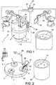
figure 1 schematically shows an axonometric view of a system according to a first embodiment; -
figure 2 shows an axonometric view of a system according to a second embodiment; -
figure 3 shows a partial section view crosswise the injection chamber of a detail of the system offigure 1 ; -
figure 4 shows an axonometric view of a detail of the system offigure 2 , in particular in a use step thereof which envisages the pouring of the molten metal in the injection chamber; -
figure 5 shows an axonometric view of a detail of the system offigure 2 , in particular in the injection chamber closing step; -
figure 6 shows a section view crosswise the injection chamber of a further detail of the system wherein the injection chamber is in a position coupled to a mould for injecting the semisolid metal into a mould chamber; -
figure 7 shows an axonometric view of an enlarged detail of the operating step offigure 4 ; -
figure 8 shows an axonometric view of another operating step of the system offigure 2 , wherein the injection chamber is closed by a cover while dipping a stirrer or mixer; -
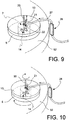
figure 9 shows an axonometric view of a detail of a further operating step of the system offigure 2 , wherein the temperature of the semisolid metal is measured before, during or after the cooling and leveling/mixing thereof; -
figure 10 shows an axonometric view of a detail of a further operating step of the system offigure 2 , wherein the molten metal is mixed, cooled and inert gas is injected; -
figure 11 shows an axonometric view of a detail of a further operating step of the system offigure 2 , wherein the cover is lifted off the injection chamber; -
figure 12 and figure 13 show axonometric side views of some details of the system for mixing the molten or semisolid metal arranged in the injection chamber; -
figure 14 shows an axonometric view of a detail according to a further embodiment of the system for mixing the molten or semisolid metal arranged in the injection chamber and closing of the same; -
figure 15 shows an axonometric view of an even further detail of an operating step of the system offigure 2 , wherein the injection chamber is approached to a mould for injecting the semisolid metal; -
figures 16, 17 and 18 show a section view of some details of the operating steps of injecting the semisolid metal into a mould; -
figure 19 shows in a Cartesian diagram showing the temperature of the semisolid metal on the abscissa and the solid metal fraction on the ordinate, a curve whereon two optimal use conditions of the system are highlighted; -
figures 20 and 21 show microphotographies of the state of the material obtained with the process described herein,figure 20 with globular solidification, and obtained with cooling in a mould according to the prior art,figure 21 with dendritic solidifications. - With reference to the above figures,
reference numeral 1 globally denotes a system. - According to an embodiment,
system 1 is a system for the injection ofsemisolid metal 3 into amould 2. - According to an embodiment, said
mould 2 comprises amould chamber 16 suitable to receive the metal through amould injection mouth 17. - According to an embodiment, said system comprises at least one
press device 4 forpressure injecting metal 3 in saidmould 2. - According to an embodiment, said at least one press device comprises a
cylinder 5 having a substantially vertical axis X-X and amouth 15 for coupling to theinjection mouth 17 of saidmould 2 as well as athrust piston 6 accommodated within said cylinder, defining with said cylinder aninjection chamber 7 suitable to containmolten metal 10. - According to an embodiment, said
cylinder 5 haspassageways 8 or inner ducts or a circuit of ducts to receivecooling fluid 9 capable of cooling saidmolten metal 10 poured into saidinjection chamber 7 converting it intosemisolid metal 3. - According to an embodiment, a
cup 18 for drawing themolten metal 10 is suitable for drawing metal and pour it into saidinjection chamber 7. - According to an embodiment, said system comprises a
positioning device 11. - According to an embodiment, said
positioning device 11 supports ablending device 12, and saidblending device 12 has anactive portion 14 and is associated with a hood orcover 13 suitable for closing saidinjection chamber 7. - According to an embodiment, said
positioning device 11 is arranged to selectively position saidblending device 12 with saidactive portion 14 within saidinjection chamber 7 and level the temperature of thesemisolid metal 3 and simultaneously to position said hood or cover 13 to temporarily close saidmouth 15 coupling thepress device 4 tomould 2. - According to an embodiment, an actuating
device 19 selectively acts on saidthrust piston 6 to inject saidsemisolid metal 3 into saidmould 2 when thecoupling mouth 15 of theinjection chamber 7 is opened and connected to theinjection mouth 17 of saidmould 2. - According to an embodiment, said system comprises a metal
temperature detecting device 21 having anactive portion 22 thereof. According to an embodiment, said metaltemperature detecting device 21 is associated with said hood orcover 13 for selectively dipping theactive portion 22 thereof into the molten orsemisolid metal cover 13 is arranged to close the mouth coupling the cylinder to mould 15. - According to an embodiment, said metal
temperature detecting device 21 is connected to acontrol device 23 ofsystem 1. According to an embodiment, said metaltemperature detecting device 21 is connected to an actuatingdevice 24 that moves the probe during the insertion of thetemperature device 21 into theinjection chamber 7 and the withdrawal of thetemperature device 21 from theinjection chamber 7. - According to an embodiment, said
thrust piston 6 comprisespassageways 25 for receivingcooling fluid 9 for cooling saidmolten metal 10. - According to an embodiment, said
passageways flow adjustment device 9 and to acooling fluid tank 54. - According to an embodiment, said cooling fluid
flow adjustment device 9 is operated in a controlled mode. - According to an embodiment, said system comprises a
temperature detection device 20 for thecooling fluid 9 provided within thecooling passageways cylinder 5 and/or of thethrust piston 6, preferably but not necessarily downstream of the cylinder and of the piston. - According to an embodiment, said cooling fluid
temperature detection device 20 is operatively connected to a control device of thesystem 23. - According to an embodiment, said cooling fluid
flow adjustment device 9 is operated in a feedback controlled mode with said cooling fluidtemperature detection device 20. - According to an embodiment, said hood or
cover 13 is associated with afeeding device 26 ofinert gas 27, such as for example but not necessarily nitrogen, into theinjection chamber 7. - According to an embodiment, said inert
gas feeding device 26 comprises anadjustment device 28 for the gas flow to be injected in theinjection chamber 7, preferably but not necessarily operated in a controlled mode. - According to an embodiment, said blending
device 12 comprises animpeller 29 having a substantially vertical X-Xrotary shaft 33 and operated by a controlledactuator 30 operatively connected to a control device of thesystem 23, preferably though not necessarily in a feedback mode. - According to an embodiment, said
impeller 29 comprises at least oneblade 31, preferably but not necessarily twoblades 31. According to an embodiment, eachblade 31 comprises anextension 32 substantially radial toshaft 33 and a rounded free end. According to an embodiment, saidimpeller 29 comprises helical blades. According to an embodiment, saidimpeller 29 has a surface treatment that reduces the adhesion of themolten metal 10. According to an embodiment, saidimpeller 29 is made of a material that reduces the adhesion of the molten metal for example though not necessarily of ceramic material. - According to an embodiment, said system comprises a
filter 35 for impurities or oxides present in themolten metal 10. Saidfilter 35 is arranged between the cup for drawing and pouring themetal 18 and theinjection chamber 7. According to an embodiment, saidfilter 35 comprises an intake duct for the molten metal, for example anintake channel 36, which is arranged such as to receive the molten metal fromcup 18 and provided with a pouringend 37 opposite to theinjection chamber 7 for the molten metal to be caused to flow intochamber 7. According to an embodiment, saidfilter 35 has in the proximity of the pouringend 37 thereof afilter portion 38 provided with passageways suitable to retain impurities and/or oxides and cause the molten metal to flow, for example though not necessarily afilter portion 38 made from ceramic material and/or comprising silicon carbides. According to an embodiment, saidfilter 35 is a disposable component that can be replaced at each pour, or after a limited number thereof, ofmolten metal 10 into theinjection chamber 7. According to an embodiment, said filter is positioned in the proximity of the injection chamber so that the cup can pour the molten metal therein through the same filter from apositioning device 55, for example a robot. - According to an embodiment, a controlled
actuator 30, for example though not necessarily a feedback actuator with a temperature signal and/or a timer, controls the movements of theblending device 12. - According to an embodiment, a controlled
actuator 24, for example though not necessarily a feedback actuator with a switch for closing the hood or cover and/or a switch for changing the system operating conditions, controls the movements of the metaltemperature detecting device 21. According to an embodiment, a controlledactuator 39, for example though not necessarily a feedback actuator with a switch for closing and opening the hood or cover, controls the inert gas inlet device within theinjection chamber 26, for example, though not necessarily, it controls the adjustment of a shut-off solenoid valve 40 of the intake flow ofinert gas 27. - According to an embodiment, a controlled
actuator 41, for example though not necessarily a feedback actuator with a switch or timer of completed-filling of theinjection chamber 7 and/or of completed-pour of the molten metal fromcup 18 and/or of positioning of thepress device 4 in the system, controls the positioning of the hood or cover 13 in order to either close or open the mouth coupling the cylinder tomould 15. - According to an embodiment, a controlled
actuator 42, for example though not necessarily a feedback actuator with a switch or timer of completed-mixing of the metal within theinjection chamber 7 and/or of opening of the hood or cover 13 and/or of positioning of thepress device 4 within the system, controls the positioning of thepress device 4 with the coupling mouth thereof ofcylinder 15 coupled to theinjection mouth 17 ofmould 2. According to an embodiment, a controlledactuator 42, for example though not necessarily a feedback actuator with a device for detecting the pressure exerted by thethrust piston 44, controls the forward movement of thethrust piston 6 to inject thesemisolid metal 3 into themould chamber 16 and to maintain the pressure until the metal has solidified. According to an embodiment, saidmould 2 comprises severalopening mould portions piece 48. According to an embodiment, a controlledactuator timer 6, controls the closure or opening of theopenable mould portions mould chamber 16 or for the opening to remove the solidifiedpiece 48. According to an embodiment, a controlledactuator 49, for example though not necessarily a feedback actuator with a temperature detection device of the cooling fluid of the cylinder and/or the piston, preferably though not necessarily arranged downstream of the cylinder and/or the thrust piston, controls the splitting of acontrol solenoid valve 50 of the cooling fluid flow ofcylinder 5 and/orpiston 6. According to an embodiment, a controlledactuator 30 of thefeedback blending device 12 in continuous or sample measurement or upon any change in the operating conditions of the metal temperature system. - According to an embodiment, a
carousel 52 is comprised for supporting a plurality ofpress devices 4 withinjection chambers 7 thereof formed by therelative cylinders 5 andpiston 6. According to an embodiment, said stations are equally spaced and simultaneously allow to load a molten metal load, close hood or cover, cool and mix the metal until it is semisolid and approach the mould to inject the semisolid metal. - According to an embodiment, a hood or cover 13 for a
system 1 for injectingsemisolid metal 3 into amould 2, wherein saidmould 2 comprises amould chamber 16 suitable for receiving the metal through amould injection mouth 17 and said system comprises at least onepress device 4 for the pressure-injection ofmetal 3 in saidmould 2, wherein said at least onepress device 4 comprises a substantially verticalaxis X-X cylinder 5 and amouth 15 for coupling to theinjection mouth 17 of saidmould 2 and athrust piston 6 accommodated within said cylinder, defining with said cylinder aninjection chamber 7 suitable for containingmolten metal 10, said hood or cover 13 being supported by apositioning device 11, wherein saidpositioning device 11 further supports ablending device 12, said blendingdevice 12 having anactive portion 14 and being associated with said hood or cover 13 and wherein saidpositioning device 11 being arranged for selectively positioning saidblending device 12 with saidactive portion 14 within saidinjection chamber 7 and levelling the temperature of thesemisolid metal 3, simultaneously positions said hood or cover 13 to temporarily close saidmouth 15 coupling thepress device 4 tomould 2. - A description is given below of some examples of methods for using a system for injecting
semisolid metal 3 in amould 2 wherein saidmould 2 comprises amould chamber 16 suitable for receiving the metal through amould injection mouth 17. - According to a general embodiment, this system is used for processing semisolid metal, for example aluminium or aluminium alloy.
- According to an embodiment, said system is provided with at least one
press device 4 associable with said mould forpressure injecting metal 3 in saidmould 2. - According to an embodiment, said at least one press device comprising a
cylinder 5 having a substantially vertical axis X-X and amouth 15 for coupling to theinjection mouth 17 of saidmould 2 and athrust piston 6 accommodated within said cylinder, defining with said cylinder aninjection chamber 7 suitable to containmolten metal 10. - According to an embodiment, said method comprises the steps of:
- drawing
molten metal 10 using acup 18 and pouring said molten metal into saidinjection chamber 7; - supporting by means of a positioning device 11 a hood or cover 13 and a
blending device 12 associated with said hood, - positioning an
active portion 14 of saidblending device 12 within saidinjection chamber 7 - positioning said hood or cover 13 to temporarily close said
mouth 15 coupling thepress device 4 tomould 2; - cooling said
molten metal 10 placed within said injection chamber by means of cooling fluid 9 provided withinpassageways 8 to receive the cooling fluid provided within said cylinder - mixing said
molten metal 10 poured into saidinjection chamber 7 with saidactive portion 14 of saidblending device 12, while said hood or cover 13 closes saidmouth 15 coupling thepress device 4 - transforming said metal in
semisolid metal 3 and levelling the temperature of thesemisolid metal 3. - Then subsequently
- injecting said
semisolid metal 3 with anactuating device 19 that selectively acts on said thrustpiston 6 into said mould when thecoupling mouth 15 of theinjection chamber 7 is open and connected to theinjection mouth 17 of saidmould 2. - According to an embodiment, a further step is provided for detecting the temperature of the metal contained within the
injection chamber 7. According to an embodiment, a metaltemperature detecting device 21 is used, provided with anactive portion 22 and theactive portion 22 of the device is dipped into the molten orsemisolid metal mould 15. - According to an embodiment, the temperature detected of the metal contained within the
injection chamber 7 is used for checking the operating steps ofsystem 1. According to an embodiment, the temperature measurement of the metal contained within theinjection chamber 7 is used to establish, when a predetermined or optimum temperature is achieved, the interruption of the metal blending and injection chamber opening step with the removal of theblending device 12. - According to an embodiment, the metal temperature is detected and the temperature is checked in order to reach a predetermined or optimum temperature by detecting the time used to blend and cool the metal to optimum condition and storing the information of the time required to blend and cool such as to be capable of using this information during successive system operating cycles thereby avoiding to use the step of detecting the temperature of the metal contained within the injection chamber at each work cycle.
- According to an embodiment, the following further step is provided:
- cooling the
thrust piston 6 which delimits theinjection chamber 7 so as to cool saidmolten metal 10. - According to an embodiment, a flow is adjusted of cooling fluid 9 provided within
passageways injection chamber 7. According to an embodiment, the cooling fluid flow is adjusted such that the temperature of the molten metal contained within theinjection chamber 7 reaches a predefined or optimum temperature level within a predetermined or limit cycle time. - According to an embodiment, the adjustment of the cooling
fluid 9 flow is carried out by detecting the temperature of the coolingfluid 9 provided within the coolingpassageways cylinder 5 and/or thrustpiston 6. - According to an embodiment, the following further step is provided:
- feeding
inert gas 27 into theinjection chamber 7 temporarily closed by the hood or cover. Advantageously, theinert gas 27 fed into theinjection chamber 7 is nitrogen. - According to an embodiment, the
gas flow 28 to be fed into theinjection chamber 7 is adjusted, preferably though not necessarily so as to achieve a predetermined or optimum flow. - According to an embodiment, a further step is provided for controlling by means of a controlled
actuator 30 theblending device 12 comprising animpeller 29 such as to adjust the rotation of said impeller, preferably though not necessarily in a feedback mode for example on the rotation speed of the impeller. According to an embodiment, the molten metal contained within theinjection chamber 7 is blended substantially in the circumferential direction using elements transversal to the walls ofcylinder 5, preferably though not necessarily by mixing along two circumferential pathways transversal to the cylinder walls and placed at two different heights relative to the bottom of theinjection chamber 7 or crown of thethrust piston 6. - According to an embodiment, the metal is blended along circumferential pathways substantially transversal to
cylinder 5 leaving a predetermined space between said wall ofcylinder 5 and theblending device 12, and/or a predetermined space between the blendingdevice 12 and thethrust piston 6. - According to an embodiment, there are provided the further steps of defining an optimum temperature of the
semisolid metal 3 contained within theinjection chamber 7, for example though not necessarily using aluminum at a temperature ranging between 580° and 600 °C, preferably though not necessarily 590 °C, gaugingsystem 1 such as to have a cooling cycle time and uniformity of temperature of thesemisolid metal 3 lower than a limit cycle time. In these conditions, the metal temperature; the rotation speed of theblending device 12; the optimum flow of the inert gas injected into theinjection chamber 7; the optimum temperature of the cooling fluid cycling withincylinder 5 and optionally of thethrust piston 6; and/or an evaluation of the flow rate of the cooling fluid are measured. - Said cycle time is set for the system for successive working steps.
- According to an embodiment, the cycle time of the blending and cooling step is recalculated only when the system parameters are changed, for example though not necessarily, using the metal temperature contained within the injection chamber and consequently by changing the blending device moving speed parameters, of the inert gas flow, of temperature or flow of the cooling fluid contained within the cylinder and/or within the thrust piston.
- According to an embodiment, during the step of pouring the
molten metal 10 fromcup 18 to theinjection chamber 7, themolten metal 10 is filtered to eliminate the impurities and/or oxides that may be present in the metal. - According to an embodiment, the metal poured from the cup into the injection chamber is filtered by means of a disposable filter, replacing said
filter 35 every one or limited number or pours of themolten metal 10 into theinjection chamber 7. - According to an embodiment, the molten metal is blended by controlling the
blending device 12 in a feedback mode using a temperature signal of the molten metal and/or a time signal of duration of the blending step. According to an embodiment, the hood or cover is moved by operating the positioning device as a function of the operating conditions of the system, for example, though not necessarily, by means of feedback operation as a function of the temperature signal of the metal provided within the injection chamber. According to an embodiment, the feeding of inert gas into the injection chamber is controlled by controlling a splitting device for the inert gas flow by means of a positioning signal of the hood and/or cover.
The method, according to anyclaim 11 to 18, wherein a stepped- or station- or phased-movement of the system is provided, wherein: - a first step of loading the molten metal into the injection chamber is provided;
- According to an embodiment:
- a second closing step with the hood or cover of the injection chamber and starting of the simultaneous mixing and cooling of the metal contained within the injection chamber is provided.
- According to an embodiment, a further step is provided for injecting inert gas into the injection chamber closed by the hood or cover.
- According to an embodiment, a further step is provided for measuring the temperature of the metal contained within the injection chamber.
- Subsequently, the step is provided of rotation and/or translation of the injection chamber at a further station.
- the injecting action is then provided by moving the thrust piston of the injection chamber when the latter is coupled to the mould.
- According to an embodiment, said stations are provided in a carrousel machine and the step is provided of moving said carrousel machine in a controlled mode, preferably though not necessarily in a feedback mode.
- Below are some operating modes of the system according to the invention.
- According to an embodiment, the process is divided into two macro steps:
- preparation of the master alloy in a holding
furnace 53 and - moulding of the piece, for example a brake caliper body, by high pressure injection after creation of the semisolid material.
-
- a) The alloy is prepared within a furnace, for example a gas furnace, wherein the chemicals are poured according to predetermined weight proportions according to predetermined procedures (or recipes).
- b) Advantageously though not necessarily, some samples of material are taken from the alloy which are subject to a chemical verification assay.
- c) A certain predetermined amount of material is poured in a furnace, called holding
furnace 53, in the vicinity of the final moulding station; a device is then dropped into said holding furnace which, by blowing inert gas that passes through a metal impeller, favors the separation of the impurities and of the hydrogen bubbles contained within the molten alloy coming from the smelting furnace. - d) The material inside the holding furnace on board of the machine is cleaned using special foundry tools, detaching the surface exposed to the air and therefore dirty with the impurities floated back up to the surface by the previous degassing process.
- e) The material contained into the holding furnace, if deemed suitable for the requirements of control specifications in terms of density and chemical composition, is ready to be used in the next moulding step.
-
- f) The arm of an electronically controlled
hand 57, at the end thereof carrying acup 18 of metal material coated with a protective coating or ceramic material, is approached to the holding furnace mouth, lowered by a predetermined distance and dipped intomaterial 10 contained within the holding furnace. - g) A predetermined amount of metal enters into the cup dipped in the holding furnace.
- h)
Hand 57 is lifted and extending an arm thereof and/or running on a suspended rail, approachesfilter 35 or device for pouring the material into the station for preparing the semisolid material. Such device consists of achannel 36 that allows the passage from the pouring cup to theinjection chamber 7 or use station; a station is created at the final end thereof for seating a filter of a predetermined material, which with its presence intercepts the flow of the liquid material and retains any impurities thereof. The filter seating station is shaped so as to allow an easy replacement of the filter once that, after each cycle or a few cycles, it ends its function and must be changed; the filter may be replaced by an operator or anelectromechanical feeding system 55. - i) Once the metal has been poured from the cup into the intake channel and then in the preparation station, the channel is moved away by a
dedicated mechanism 55. - j) The station for preparing the metal (referred to as injection container or injection chamber 7) consists of a
metal cylinder 5 the walls whereof are cooled by the circulation of heat-regulated water the temperature whereof is displayed by an electronic central unit for any checks. The container bottom consists of the crown of ahydraulic piston 6 that shall be used for moulding the caliper, as shall be described hereinafter; also the injection piston is cooled by a liquid at predetermined and displayed temperature. According to an embodiment, the container is mounted with two more containers on a metal plate (referred to as carousel 52) in positions forming angles of 120°. - k) A
second hand 11 or robot approaches the station for preparing the semisolid metal; the mixing or blendingdevice 12 is mounted at the end of the arm thereof integral with a metal cover orhood 13, with a station wherein aretractable thermocouple 21 is seated. The metal hood is connected to the device for feeding inert gas into theinjection chamber 26, for example a tube, with a flow meter and a second tube up to an inert gas distribution system: during the semisolid metal preparation cycle, the inert gas is injected in the space between the hood and the metal that must be processed. This implies the forming of an inert gas atmosphere that prevents the contact of the alloy contained into the device with the outer environment. - l) The hood is integral with a device for seating a temperature detecting system 21 (referred to as thermocouple) the
end 22 whereof (hot joint) may be dipped into the material contained in the blending station. The thermocouple therefore is retractable and may be dipped in the material every moulding cycle or every given predetermined number of cycles; since it is connected to the centralelectronic station 23, the temperature values are stored for subsequent analyses or checks. - m) The hood is integral to a device for seating a
blending system 12 for the metal contained in the station, operated by arobot 11 that rotates it on itself at a predetermined speed controlled by thecentral unit 23. The mechanical blending action and the cooling induced by the container favor the forming of the semisolid metal layer by the formation of a plurality of solidification cores that grow with a globular morphology also by the effect of the sliding gradient induced by the blending device. - n) The
blending system 14, of pre-coated metal or ceramic material, consists of a cylindrical device orshaft 33 for fixing to the rotary shaft, whereto two flat metal devices are fixed, orblades 31, developed in horizontal direction relative to the container walls, which are vertical. The end of the two horizontal devices (referred to as blades 31) are radiused with a radius equal to half the height of the same; the two blades are integrally connected to the shaft orcentral shaft 33, mounted on the opposite side and at a different height. - o) As an alternative, a helical (propeller) blending device may be used.
- p) Once the semisolid metal has been created,
carousel 52 rotates by 120° and the container with the metal moves underneath the injection machine whereonmould 2 is mounted; an interlocking system lifts the container and the piston integral thereto, ensuring the perfect contact with the bottom portion of the mould. - q) Thereafter, the thrust or
injection piston 6 is activated and lifted by such a distance as to favor the injection of thesemisolid metal 3 intocavity 16 contained withinmould 2; all the operations and the relative physical quantities are controlled and recorded by the electroniccentral unit 23 for subsequent analyses and checks. - r) Once a predetermined period of time has passed, which favors the complete solidification of the metal injected and wherein pressure is kept to the maximum value compatible with the machine potential, the
upper mould 46 is lifted, dragging the caliper thus formed therewith (Figure 18 ). The bottom portion of the casting (the caliper) which connects it to the metal still in the container is designed with such a geometry as to have a minimum section which during the movement of the casting dragged by the mould is torn and allows the separation between caliper and inlet channel ormould injection mouth 17. The metal portion that remains in the container remains attached thanks to the shape of the piston crown: a suitable design provides for the material-piston interface to have a "dovetail" geometry, i.e. has undercut portions that lock the material into the piston. When the piston retracts it drags the "hooked" material, the caliper is integral to the upper mould that lifts and the above minimum section tears apart, separating the caliper from the channel. - s) The casting that is still integral to the upper mould is detached thanks to the action of the mould ejectors; the operator or alternatively a robot system grips the caliper and places it in a previously determined zone.
- t) The final step of the moulding cycle envisages the rotation of
carousel 52 by 120° with the container in the last position of the carousel, where the portion of metal detached from the caliper according to what described in paragraph r) is automatically injected. - u) The moulding cycle resumes from step f).
- Thanks to the proposed system and method it is possible to obtain castings free from oxides and films or impurities that create structural discontinuities.
- Moreover, thanks to the system and method according to any one of the embodiments described above it is possible to obtain castings both with minimum solidification shrinkage (thanks to the moulding in semisolid phase) and free from air entrapment (thanks to the mould filling with laminar movement) so as to allow the execution of heat purification treatments thereon (without the onset of surface blisters) capable of imparting high mechanical features to the same castings.
- In the practice, thanks to the system and method according to any one of the embodiments described above it is possible to obtain structural pieces having a high or very high metallurgic quality.
- In particular, thanks to the provision of the hood or cover for closing the injection chamber during the cooling and blending, it is possible to ensure the exclusion of impurity entrapment. Advantageously, the injection or washing of the atmosphere of the injection chamber closed by the cover with inert gas in overpressure allows the exclusion of not only impurities but also of oxides in the semisolid metal and thus in the casting to be even more ensured during the blending of the metal in semisolid metal, also preventing the forming of dangerous films.
- According to an embodiment, it has been proven that a 22 liter/min rate is optimum for washing an injection chamber having dimensions of 180 mm diameter and 150 mm depth, wherein about 1/3 volume remains as free atmosphere.
- Thanks in particular to the provision of a filter between the cup and the injection chamber, for example preferably a disposable filter, it is possible to ensure the absence of oxide films that in the chamber and in the casting would bend on themselves, creating very harmful structural discontinuities.
- Thanks to the provision of a cover for closing the injection chamber and optionally of the washing of the residual chamber atmosphere with inert gas it is possible to increase the blending speed preventing the entrapment of air into the metal and the forming of oxides and greatly reducing the semisolid forming times and thus the process cycle times. For example, in an injection chamber having dimensions of 180 mm diameter and 150 mm depth wherein about 1/3 volume is left as free atmosphere, cycle times have been obtained of about 10 seconds, maintaining an excellent metallurgic quality of the casting.
- Thanks to the metal temperature measurement in the injection chamber it is possible to check the semisolid metal forming process adjusting the cycle times or other system operating parameters to obtain a metal having optimum conditions.
- For example, controlling the semisolid metal temperature, even occasionally, for example when the system operating conditions change, allows the mould cavity to be fully filled allowing this method to be used also for castings with very complex shapes and/or allows the solid fraction provided in the metal to be maximized, for example achieving even 40%-50% by volume and/or allows the semisolid metal blending times to be changed according, for example, to the alloy in any case ensuring a casting with optimum metallurgic quality.
- For example though not necessarily, the aluminum alloy temperature may be set to 590 °C and accordingly the blending cycle times and the cooling fluid flow rate may be calculated, optimizing the cycle times so that they are shorter than a predetermined limit time (for example 12 seconds).
- Thanks to the systems and methods described above it is advantageously possible to obtain an optimum uniformity of the temperature in the semisolid metal mass provided in the injection chamber, ensuring an optimum casting uniformity.
- Thanks to the systems and methods described above it is advantageously possible to obtain a particular promotion of the solidification cores in the molten metal, making the semisolid metal provided with a larger amount of solidified globules and with more even dimension and smaller dimensions than the known prior art methods.
- It is clear that a man skilled in the art may make several changes and variations in order to meet specific and incidental needs, all falling within the scope of protection of the invention as defined by the following claims.
REFERENCES 1 system 28 gas flow adjustment device 2 mould 29 impeller 3 semisolid metal 30 impeller control actuator 4 press device 31 blade 5 cylinder 32 blade radial extension 6 thrust piston 33 impeller shaft 7 injection chamber 34 impeller surface treatment 8 cooling passageways 35 filter for molten metal impurities 9 cooling fluid 36 molten metal intake channel 10 molten metal 37 pouring end 11 positioning 38 filter portion with passageways for 12 blending 39 controlled actuator for inert gas flow 13 hood or cover 40 solenoid valve 14 active portion of blending 41 controlled cover actuator 15 coupling mouth of cylinder 42 controlled actuator for press device 16 mould chamber 43 controlled piston thrust actuator 17 mould injection mouth 44 piston-exerted pressure sensor 18 metal drawing and 45 mould opening closing actuator 19 thrust piston actuator 46 opening mould portions 20 cooling fluid temperature detection device 47 opening mould portions 21 metal temperature detection device 48 solidified piece 22 temperature probe active portion 49 controlled actuator for cylinder and/or piston cooling fluid flow adjustment solenoid valve 23 system control device 50 cooling fluid flow splitting solenoid 24 device for actuating and moving the temperature probe to and from the 51 cooling fluid intake pump 25 passageways for cooling fluid provided in piston 52 carousel supporting a plurality of press device stations 26 device for feeding inert gas into the injection 53 molten metal holding furnace 27 inert gas to molten metal 54 cooling fluid tank X-X injection chamber vertical axis 55 filter positioning device 56 mould opening closing actuator 57 cup handling device
Claims (15)
- A system (1) for injecting semisolid metal (3) into a mould (2), comprising:- said mould (2) comprising a mould chamber (16) suitable to receive the metal through a mould injection mouth (17);- at least one press device (4) for pressure-injecting metal (3) in said mould (2);- said at least one press device comprising a cylinder (5) having a substantially vertical axis (X-X) and a mouth (15) for coupling to the injection mouth (17) of said mould (2) and a thrust piston (6) accommodated within said cylinder, defining with said cylinder an injection chamber (7) suitable to contain molten metal (10);- said cylinder (5) having passageways (8) to receive cooling fluid (9) of said molten metal (10) poured into said injection chamber (7) in semisolid metal (3);- a cup (18) for drawing the molten metal (10) and pouring the latter into said injection chamber (7);- a positioning device (11);- said positioning device (11) supporting a blending device (12), said blending device (12) having an active portion (14) and being associated with a hood or cover (13);- said positioning device (11) being arranged to selectively positioning said blending device (12) with said active portion (14) in said injection chamber (7) and leveling the temperature of the semisolid metal(3) and simultaneously to positioning said hood or cover (13) in order to temporarily close said mouth (15) coupling the press device (4) to the mould (2);- an actuating device (19) that selectively acts on said thrust piston (6) to inject said semisolid metal (3) into said mould (2) when the coupling mouth (15) of the injection chamber (7) is opened and connected to the injection mouth (17) of said mould (2).
- The system (1), according to claim 1, wherein a metal temperature detecting device (21) is comprised, which has an active portion (22), said metal temperature detecting device (21) being associated with said hood or cover (13) to selectively dip the active portion (22) thereof into the molten or semi-solid metal (10, 3) when the hood or cover (13) is arranged to close the mouth coupling the cylinder to the mould (15) and/or wherein said metal temperature detecting device (21) is connected to a control device (23) of the system (1) and/or wherein said metal temperature detecting device (21) is connected to an actuating device (24) that moves the probe during the insertion of the temperature device (21) into the injection chamber (7) and the withdrawal of the temperature device (21) from the injection chamber (7).
- The system, according to claim 1 or 2, wherein said thrust piston (6) comprises passageways (25) to receive cooling fluid (9) for cooling said molten metal (10) and/or wherein said passageways (8, 25) of said cylinder and said piston are in fluid connection with a cooling circuit connected to a cooling fluid flow adjustment device (9) and/or wherein said cooling fluid flow adjustment device (9) is operated in a controlled mode.
- The system according to any preceding claim, wherein a temperature detection device (20) is comprised for the cooling fluid (9) provided within the cooling passageways (8, 25) of the cylinder (5) and/or thrust piston (6), preferably but not necessarily downstream of the cylinder and piston; and/or wherein said cooling fluid temperature detection device (20) is operatively connected to a control device (23); and/or wherein said cooling fluid flow adjustment device (9) is operated in a feedback controlled mode with said cooling fluid temperature detection device (20).
- The system according to any preceding claim, wherein said hood or cover (13) is associated with a device (26) for feeding inert gas (27) into the injection chamber (7), such as for example though not necessarily nitrogen and/or wherein said inert gas feeding device (26) comprises an adjustment device (28)for the gas flow to be injected into the minjection chamber (7), preferably though not necessarily operated in a controlled mode.
- The system according to any preceding claim, wherein said blending device (12) comprises an impeller (29) having a substantially vertical (X-X) rotary shaft (33) and operated by a controlled actuator (30) being operatively connected to a control device of the system (23) preferably though not necessarily in a feedback mode; and/or wherein said impeller (29) comprises at least one blade (31), preferably though not necessarily two blades (31), and/or wherein each blade (31) comprises an extension (32) substantially radial to the shaft (33) and a rounded free end; and/or wherein said impeller (29) comprises helical blades; and/or wherein said impeller (29) has a surface treatment (34) that reduces the adhesion of the molten metal (10); and/or wherein said impeller (29) is made of a material that reduces the adhesion of the molten metal for example though not necessarily of ceramic material.
- The system according to any preceding claim, wherein a filter (35) is comprised for the impurities or oxides present in the molten metal (10), which is arranged between the cup for drawing and pouring the metal (18) and the injection chamber (7); and/or wherein said filter (35) comprises an intake duct for the molten metal, for example an intake channel (36), which is arranged such as to receive the molten metal from the cup (18) and provided with a pouring end (37) opposite to the injection chamber (7) for the molten metal to be caused to flow into the chamber (7); and/or wherein said filter (35) has at the pouring end (37) thereof a filter portion (38) provided with passageways that are suitable to retain impurities and/or oxides and cause the molten metal to flow, for example though not necessarily a filter portion (38) made from ceramic material and/or comprising silicon carbides; and/or wherein said filter (35) is a disposable component that can be replaced at each pour, or after a limited number thereof, of molten metal (10) into the injection chamber(7).
- The system according to any preceding claim, wherein a controlled actuator (30), for example but not necessarily a feedback actuator with a temperature signal and/or a timer, controls the movements of the blending device (12); and/or wherein a controlled actuator (24), for example though not necessarily a feedback actuator with a closing switch for the hood or cover and/or a switch for changing the system operating conditions, controls the movements of the metal temperature detecting device (21); and/or wherein a controlled actuator (39), for example though not necessarily a feedback actuator with a switch for closing and opening the hood or cover, controls the inert gas inlet device within the injection chamber (26) for example, though not necessarily, it controls the adjustment of a shut-off solenoid valve (40) of the intake flow of inert gas (27); and/or wherein a controlled actuator (41), for example though not necessarily a feedback actuator with a switch or timer of completed-filling of the injection chamber (7) and/or of completed-pour of the cup (18) and/or of positioning of the press device (4) in the system, controls the positioning of the cap or cover (13) in order to either close or open the mouth coupling the cylinder to the mould (15); and/or wherein a controlled actuator (42), for example though not necessarily a feedback actuator with a switch or timer of completed-mixing of the metal within the injection chamber (7) and/or of opening of the hood or cover (13) and/or of positioning of the press device (4) within the system, controls the positioning of the press device (4) with the coupling mouth of the cylinder (15) being coupled to the injection mouth (17) of the mould (2); and/or wherein a controlled actuator (43), for example though not necessarily a feedback actuator with a device for detecting the pressure exerted by the thrust piston (44), controls the forward movement of the thrust piston (6) to inject the semisolid metal (3) into the mould chamber (16) and to maintain the pressure until the metal has solidified, and/or wherein said mould (2) comprises several openable mould portions (46, 47) to remove the solidified piece (48) and/or wherein a controlled actuator (45), for example though not necessarily a feedback actuator with a piston end-of-thrust switch or timer (6), controls the closure or opening of the openable mould portions (46, 47) for the closure to form the mould chamber (16) or for the opening to remove the solidified piece (48); and/or wherein a controlled actuator (49), for example though not necessarily a feedback actuator with a temperature detection device of the cooling fluid of the cylinder and/or the piston preferably though not necessarily arranged downstream of the cylinder and/or the thrust piston, controls the slicing of a control solenoid valve (50) of the cooling fluid flow of cylinder (5) and/or piston (6), and/or controls an intake pump (51) of the cooling fluid flow of cylinder (5) and/or piston (6); and/or wherein the controlled actuator (30) of the feedback blending device (12) in continuous or sample measurement or upon any change in the operating conditions of the metal temperature system.
- The system according to any preceding claim, wherein a carousel (52) is comprised supporting a plurality of press devices (4) with injection chambers (7) thereof being formed from the relevant cylinders (5) piston (6); and/or wherein said stations are equally spaced and simultaneously allow to load molten metal load, close hood or cover, cooling and mixing metal until it is semi-solid and approach mould to inject semisolid metal.
- A method for the injection of semisolid metal (3) into a mould (2), wherein:- said mould (2) comprises a mould chamber (16) suitable to receive the metal through a mould injection mouth (17);- at least one press device (4) is provided which can be associated with said mould for the press-injection of metal (3) into said mould (2);- said at least one press device comprising a cylinder (5) having a substantially vertical axis (X-X) and a coupling mouth (15) at the injection mouth (17) of said mould (2) and a thrust piston (6) accommodated within said cylinder, defining with said cylinder an injection chamber (7) suitable to contain molten metal (10);said method comprising the steps of:- drawing molten metal (10) using a cup (18) and pouring said molten metal into said injection chamber (7);supporting by means of a positioning device (11) a hood or cover (13) and a blending device (12) associated with said hood,- positioning an active portion (14) of said blending device (12) within said injection chamber (7)and simultaneously- positioning said hood or cover (13) to temporarily close said mouth (15) coupling the press device (4) to the mould (2);- and simultaneously cooling said molten metal (10) placed within said injection chamber by means of cooling fluid (9) provided within passageways (8) to receive the cooling fluid provided within said cylinder (5) and simultaneously- mixing said molten metal (10) poured into said injection chamber (7) with said active portion (14) of said blending device (12), while said hood or cover (13) closes said mouth (15) coupling the press device (4)- transforming said metal in semisolid metal (3) and leveling the temperature of the semisolid metal (3) then subsequently- injecting said semisolid metal (3) with an actuating device (19) that selectively acts on said thrust piston (6) into said mould (2) when the coupling mouth (15) of the injection chamber (7) is open and connected to the injection mouth (17) of said mould (2).
- The method, according to claim 10, wherein the further step is comprised of:- detecting the temperature of the metal contained within the injection chamber (7); and/or wherein the use of a metal temperature detecting device (21) is provided, which is provided with an active portion (22) and the active portion (22) of the device is dipped into the molten or semisolid metal (10, 3) while the hood or cover (13) is placed to close the mouth coupling the cylinder to the mould (15); and/or wherein the temperature detected of the metal contained within the injection chamber (7) is used to check the operating steps of the system (1); and/or wherein the temperature measurement of the metal contained within the injection chamber (7) is used to establish, when a predetermined or optimum temperature is achieved, the interruption of the metal blending and injection chamber opening step with the removal of the blending device (12) and/or wherein the metal temperature is detected and the temperature is checked in order to reach a predetermined or optimum temperature by detecting the time used to blend and cool the metal to optimum condition and storing the information of the time required to blend and cool such as to be capable of using this information during successive system operating cycles thereby avoiding to use the step of detecting the temperature of the metal contained within the injection chamber at each work cycle; and/orwherein the further step is provided of:- cooling the thrust piston (6) that defines the injection chamber (7), such as to cool said molten metal (10); and/or wherein a flow is adjusted of cooling fluid (9) provided within passageways (8, 25) provided within the cylinder and within the thrust piston; and/or wherein said adjustment is carried out in a controlled mode by detecting the temperature of the metal contained within the injection chamber (7); and/or wherein the cooling fluid flow is adjusted such that the temperature of the molten metal contained within the injection chamber (7) reaches a predefined or optimum temperature level within a predetermined or limit cycle time; and/or wherein the adjustment of the cooling fluid (9) flow is carried out by detecting the temperature of the cooling fluid (9) provided within the cooling passageways (8, 25) of the cylinder (5) and/or thrust piston (6); and/orwherein the further step is provided of:- feeding inert gas (27) into the injection chamber (7) temporarily closed by the hood or cover (13), such as for example though not necessarily nitrogen; and/or wherein the gas flow (28) to be fed into the injection chamber (7) is adjusted, preferably though not necessarily, such as to achieve a predetermined or optimum flow.
- The method, according to any claim 10 to 11, wherein the further step is provided of:- controlling by means of a controlled actuator (30) the blending device (12) comprising an impeller (29) such as to adjust the rotation of said impeller, preferably though not necessarily in a feedback mode for example on the rotation speed of the impeller and/or wherein the molten metal contained within the injection chamber (7) is blended substantially in the circumferential direction using elements transversal to the walls of the cylinder (5), preferably though not necessarily by mixing along two circumferential pathways transversal to the cylinder walls and placed at two different heights relative to the bottom of the injection chamber (7) or crown of the thrust piston (6); and/or wherein the metal is blended along circumferential pathways substantially transversal to the cylinder (5) leaving a predetermined space between said wall of the cylinder (5) and the blending device (12), and/or a predetermined space between the blending device (12) and the thrust piston (6); and/orwherein the further steps are provided of:- defining an optimum temperature of the semisolid metal (3) contained within the injection chamber (7), for example though not necessarily using aluminum at a temperature ranging between 580° and 600°C, preferably though not necessarily 590°C,- gauging the system (1) such as to have a cooling cycle time and uniformity of temperature of the semisolid metal (3) lower than a limit cycle time;- in these conditions, the metal temperature; the rotation speed of the blending device (12); the optimum flow of the inert gas injected into the injection chamber (7); the optimum temperature of the cooling fluid cycling within the cylinder (5) and optionally of the thrust piston (6); and/or an evaluation of the flow rate of the cooling fluid are measured;- this cycle time is set for the system for successive working steps;and/or wherein the cycle time of the blending and cooling step is recalculated only when the system parameters are changed, for example though not necessarily, using the metal temperature contained within the injection chamber and consequently by changing the blending device moving speed parameters, of the inert gas flow, of temperature or flow of the cooling fluid contained within the cylinder and/or within the thrust piston.
- The method according to any claim 10 to 12, wherein during the step of pouring the molten metal (10) from the cup (18) to the injection chamber (7), the molten metal (10) is filtered to eliminate the impurities and/or oxides that may be present in the metal; and/or wherein the metal poured from the cup into the injection chamber is filtered by means of a disposable filter, by replacing said filter (35) every one or limited number or pours of the molten metal (10) into the injection chamber (7).
- The method according to any claim 10 to 13, wherein:- the molten metal is blended by controlling the blending device (12) in a feedback mode using a temperature signal of the molten metal and/or a time signal of duration of the blending step; and/or wherein the hood or cover is moved by operating the positioning device as a function of the operating conditions of the system for example, though not necessarily, by means of feedback operation as a function of the temperature signal of the metal provided within the injection chamber; and/or wherein the feeding of inert gas into the injection chamber is controlled by controlling a splitting device for the inert gas flow by means of a positioning signal of the hood and/or cover.
- The method, according to any claim 10 to 14, wherein a stepped- or station- or phased-movement of the system is provided, wherein:- a first step of loading the molten metal into the injection chamber is provided;- a rotation and/or translation which shifts the injection chamber to a second station is provided;- a second closing step with the hood cover or cover of the injection chamber and starting of the simultaneous mixing and cooling of the metal contained within the injection chamber is provided;and/or wherein the further step is provided of injecting the inert gas into the injection chamber closed by the hood and/or lid and/or measuring the temperature of the metal contained within the injection chamber;- subsequently, the step is provided of rotation and/or translation of the injection chamber at a further station;- the injecting action is then provided by moving the thrust piston of the injection chamber when the latter is coupled to the mould;and/or wherein said stations are provided in a carrousel machine and the step is provided of moving said carrousel machine in a controlled mode, preferably though not necessarily in a feedback mode.
Applications Claiming Priority (2)
| Application Number | Priority Date | Filing Date | Title |
|---|---|---|---|
| IT000903A ITMI20110903A1 (en) | 2011-05-20 | 2011-05-20 | PLANT AND METHOD FOR INJECTION IN SEMISOLID ALUMINUM MOLD |
| EP12731688.3A EP2709781B1 (en) | 2011-05-20 | 2012-05-15 | System and method for injecting semisolid aluminium into a mould |
Related Parent Applications (2)
| Application Number | Title | Priority Date | Filing Date |
|---|---|---|---|
| EP12731688.3A Division-Into EP2709781B1 (en) | 2011-05-20 | 2012-05-15 | System and method for injecting semisolid aluminium into a mould |
| EP12731688.3A Division EP2709781B1 (en) | 2011-05-20 | 2012-05-15 | System and method for injecting semisolid aluminium into a mould |
Publications (1)
| Publication Number | Publication Date |
|---|---|
| EP3216541A1 true EP3216541A1 (en) | 2017-09-13 |
Family
ID=44555086
Family Applications (2)
| Application Number | Title | Priority Date | Filing Date |
|---|---|---|---|
| EP12731688.3A Active EP2709781B1 (en) | 2011-05-20 | 2012-05-15 | System and method for injecting semisolid aluminium into a mould |
| EP17166771.0A Withdrawn EP3216541A1 (en) | 2011-05-20 | 2012-05-15 | System and method for injecting semisolid aluminum into a mould |
Family Applications Before (1)
| Application Number | Title | Priority Date | Filing Date |
|---|---|---|---|
| EP12731688.3A Active EP2709781B1 (en) | 2011-05-20 | 2012-05-15 | System and method for injecting semisolid aluminium into a mould |
Country Status (5)
| Country | Link |
|---|---|
| US (1) | US9724753B2 (en) |
| EP (2) | EP2709781B1 (en) |
| CN (1) | CN103717327B (en) |
| IT (1) | ITMI20110903A1 (en) |
| WO (1) | WO2012160479A1 (en) |
Families Citing this family (16)
| Publication number | Priority date | Publication date | Assignee | Title |
|---|---|---|---|---|
| US10029366B2 (en) * | 2014-11-21 | 2018-07-24 | Canon Kabushiki Kaisha | Control device for motor drive device, control device for multi-axial motor, and control method for motor drive device |
| EP3268983A4 (en) * | 2015-03-10 | 2018-07-25 | Honeywell International Inc. | Method of purifying and casting materials |
| CN104785786B (en) * | 2015-04-24 | 2017-04-05 | 江苏科技大学 | One kind send paddle metal parts increasing material manufacturing method and device |
| CN104907527A (en) * | 2015-06-17 | 2015-09-16 | 深圳领威科技有限公司 | Semi-solid pulping equipment, semi-solid pulping system and semi-solid pulping method |
| CN105127398B (en) * | 2015-09-09 | 2018-02-23 | 东莞市隆盛智能装备有限公司 | Multi-station full-automatic feeding device |
| WO2018068526A1 (en) * | 2016-10-12 | 2018-04-19 | 福建省瑞奥麦特轻金属有限责任公司 | Aluminum alloy semi-solid forming method and device |
| IT201700008841A1 (en) | 2017-01-27 | 2018-07-27 | Fonderia Gattelli S R L | MACHINE AND METHOD OF PRESSOCOLATE IN SEMISOLIDO |
| CN107457382B (en) * | 2017-08-28 | 2023-04-28 | 广东工业大学 | A semi-solid rheological die-casting production device |
| WO2019123223A1 (en) * | 2017-12-20 | 2019-06-27 | Freni Brembo S.P.A. | Method of making a porous preform in silicon carbide with controlled porosity and silicon carbide porous preform |
| CN109865812B (en) * | 2019-03-29 | 2020-10-27 | 东北大学 | A metal rheological purification pressure forming equipment |
| KR102571748B1 (en) * | 2021-05-04 | 2023-08-25 | 세메스 주식회사 | Apparatus and method for treating substrate |
| CN113352519B (en) * | 2021-05-26 | 2022-06-28 | 深圳市旭龙光电有限公司 | Pouring equipment for production of organic glass pouring plate |
| CN114309524A (en) * | 2021-11-26 | 2022-04-12 | 深圳南科强正轻合金技术有限公司 | Quality online monitoring system and method for semi-solid slurry |
| CN118385522B (en) * | 2023-12-21 | 2024-12-13 | 江苏华阀科技有限公司 | Die-casting forming die capable of reducing air holes in valve body |
| WO2026083113A1 (en) * | 2024-10-18 | 2026-04-23 | Gissco Company Limited | Apparatus and method for casting metal parts |
| CN121026942B (en) * | 2025-10-29 | 2026-01-30 | 重庆哈丁环境试验技术股份有限公司 | A composite fluid contamination testing device |
Citations (5)
| Publication number | Priority date | Publication date | Assignee | Title |
|---|---|---|---|---|
| US3954455A (en) | 1973-07-17 | 1976-05-04 | Massachusetts Institute Of Technology | Liquid-solid alloy composition |
| WO2000005015A1 (en) | 1998-07-24 | 2000-02-03 | Gibbs Die Casting Aluminum Corporation | Semi-solid casting apparatus and method |
| US6808004B2 (en) | 2002-01-31 | 2004-10-26 | Tht Presses Inc. | Semi-solid molding method |
| US6901991B2 (en) | 2002-01-31 | 2005-06-07 | Tht Presses Inc. | Semi-solid molding apparatus and method |
| US7441584B2 (en) | 2006-03-02 | 2008-10-28 | T.H.T Presses, Inc. | Semi-solid molding method and apparatus |
Family Cites Families (4)
| Publication number | Priority date | Publication date | Assignee | Title |
|---|---|---|---|---|
| EP0937524A1 (en) * | 1998-02-19 | 1999-08-25 | Fondarex S.A. | Method for de-aerating of die casting moulds and valve apparatus for carrying out the process |
| US6742567B2 (en) * | 2001-08-17 | 2004-06-01 | Brunswick Corporation | Apparatus for and method of producing slurry material without stirring for application in semi-solid forming |
| JP3549055B2 (en) * | 2002-09-25 | 2004-08-04 | 俊杓 洪 | Die casting method for metal material molding in solid-liquid coexistence state, apparatus therefor, die casting method for semi-solid molding and apparatus therefor |
| US20110049197A1 (en) * | 2009-08-06 | 2011-03-03 | Paul Anthony Withey | Liquid device having filter |
-
2011
- 2011-05-20 IT IT000903A patent/ITMI20110903A1/en unknown
-
2012
- 2012-05-15 WO PCT/IB2012/052422 patent/WO2012160479A1/en not_active Ceased
- 2012-05-15 EP EP12731688.3A patent/EP2709781B1/en active Active
- 2012-05-15 EP EP17166771.0A patent/EP3216541A1/en not_active Withdrawn
- 2012-05-15 US US14/118,253 patent/US9724753B2/en active Active
- 2012-05-15 CN CN201280035682.9A patent/CN103717327B/en active Active
Patent Citations (5)
| Publication number | Priority date | Publication date | Assignee | Title |
|---|---|---|---|---|
| US3954455A (en) | 1973-07-17 | 1976-05-04 | Massachusetts Institute Of Technology | Liquid-solid alloy composition |
| WO2000005015A1 (en) | 1998-07-24 | 2000-02-03 | Gibbs Die Casting Aluminum Corporation | Semi-solid casting apparatus and method |
| US6808004B2 (en) | 2002-01-31 | 2004-10-26 | Tht Presses Inc. | Semi-solid molding method |
| US6901991B2 (en) | 2002-01-31 | 2005-06-07 | Tht Presses Inc. | Semi-solid molding apparatus and method |
| US7441584B2 (en) | 2006-03-02 | 2008-10-28 | T.H.T Presses, Inc. | Semi-solid molding method and apparatus |
Also Published As
| Publication number | Publication date |
|---|---|
| EP2709781B1 (en) | 2017-07-05 |
| US9724753B2 (en) | 2017-08-08 |
| WO2012160479A1 (en) | 2012-11-29 |
| CN103717327B (en) | 2016-12-28 |
| EP2709781A1 (en) | 2014-03-26 |
| US20140182806A1 (en) | 2014-07-03 |
| ITMI20110903A1 (en) | 2012-11-21 |
| CN103717327A (en) | 2014-04-09 |
Similar Documents
| Publication | Publication Date | Title |
|---|---|---|
| EP2709781B1 (en) | System and method for injecting semisolid aluminium into a mould | |
| US20080202644A1 (en) | Quiescent transfer of melts | |
| CN1733394B (en) | Metal automatic casting device and method | |
| US8302659B2 (en) | Method and device for casting a cast part from a metal melt | |
| EP0645206A1 (en) | Method and system for semiliquid die casting high performance mechanical components from rheocast ingots | |
| US20140251572A1 (en) | Vacuum or air casting using induction hot topping | |
| US8245759B2 (en) | Ladle for molten metal | |
| CN207703001U (en) | A kind of anti-splashing aluminum alloy smelting furnace feeding equipment | |
| KR101992836B1 (en) | Injection molding apparatus | |
| CN119779027B (en) | Nickel-based alloy casting equipment and casting method | |
| DE19821946A1 (en) | Automatic casting of components by filling a measured volume with metal melt | |
| US8418745B2 (en) | Pour ladle for molten metal | |
| CN106834762B (en) | A kind of vacuum melting device of intermetallic Ni-Al compound | |
| RU120026U1 (en) | DEVICE FOR CENTRIFUGAL CASTING OF RING CASTINGS IN AN INERT GAS | |
| CN109913711A (en) | Cast aluminium alloy gold molding machine and forming method | |
| US4436142A (en) | Method and apparatus for making ductile iron castings | |
| JP4239160B2 (en) | Low pressure casting system | |
| JPH07509664A (en) | Casting method and equipment for parts | |
| CN215237671U (en) | Blank casting alloy filling device | |
| CN113263168B (en) | Pouring method of ladle | |
| WO2021044111A1 (en) | Casting apparatus | |
| CN206356563U (en) | A kind of diecasting alloys Duplex melting device | |
| JPH0428467B2 (en) | ||
| JPH06269920A (en) | Trough type molten metal supplying method and its device | |
| JPH02241650A (en) | Apparatus for pouring molten metal |
Legal Events
| Date | Code | Title | Description |
|---|---|---|---|
| PUAI | Public reference made under article 153(3) epc to a published international application that has entered the european phase |
Free format text: ORIGINAL CODE: 0009012 |
|
| AC | Divisional application: reference to earlier application |
Ref document number: 2709781 Country of ref document: EP Kind code of ref document: P |
|
| AK | Designated contracting states |
Kind code of ref document: A1 Designated state(s): AL AT BE BG CH CY CZ DE DK EE ES FI FR GB GR HR HU IE IS IT LI LT LU LV MC MK MT NL NO PL PT RO RS SE SI SK SM TR |
|
| 17P | Request for examination filed |
Effective date: 20180219 |
|
| RBV | Designated contracting states (corrected) |
Designated state(s): AL AT BE BG CH CY CZ DE DK EE ES FI FR GB GR HR HU IE IS IT LI LT LU LV MC MK MT NL NO PL PT RO RS SE SI SK SM TR |
|
| STAA | Information on the status of an ep patent application or granted ep patent |
Free format text: STATUS: THE APPLICATION IS DEEMED TO BE WITHDRAWN |
|
| 18D | Application deemed to be withdrawn |
Effective date: 20180314 |