EP3216487A1 - System and method for creating sterile connections using ultraviolet light - Google Patents
System and method for creating sterile connections using ultraviolet light Download PDFInfo
- Publication number
- EP3216487A1 EP3216487A1 EP17159027.6A EP17159027A EP3216487A1 EP 3216487 A1 EP3216487 A1 EP 3216487A1 EP 17159027 A EP17159027 A EP 17159027A EP 3216487 A1 EP3216487 A1 EP 3216487A1
- Authority
- EP
- European Patent Office
- Prior art keywords
- coupler
- connectors
- connector
- holder
- housing
- Prior art date
- Legal status (The legal status is an assumption and is not a legal conclusion. Google has not performed a legal analysis and makes no representation as to the accuracy of the status listed.)
- Granted
Links
- 238000000034 method Methods 0.000 title claims description 27
- 239000012530 fluid Substances 0.000 claims abstract description 58
- 230000007704 transition Effects 0.000 claims abstract description 4
- 230000001678 irradiating effect Effects 0.000 claims description 5
- 238000004891 communication Methods 0.000 claims description 3
- 230000008878 coupling Effects 0.000 claims description 3
- 238000010168 coupling process Methods 0.000 claims description 3
- 238000005859 coupling reaction Methods 0.000 claims description 3
- 238000007789 sealing Methods 0.000 claims description 2
- 239000000463 material Substances 0.000 description 10
- 230000007246 mechanism Effects 0.000 description 9
- 238000012545 processing Methods 0.000 description 9
- 230000008569 process Effects 0.000 description 4
- 230000001954 sterilising effect Effects 0.000 description 4
- 238000004659 sterilization and disinfection Methods 0.000 description 4
- 238000013461 design Methods 0.000 description 3
- 238000010586 diagram Methods 0.000 description 3
- 229920000089 Cyclic olefin copolymer Polymers 0.000 description 2
- 239000004713 Cyclic olefin copolymer Substances 0.000 description 2
- 230000008901 benefit Effects 0.000 description 2
- 239000008280 blood Substances 0.000 description 2
- 210000004369 blood Anatomy 0.000 description 2
- 238000010276 construction Methods 0.000 description 2
- 239000003814 drug Substances 0.000 description 2
- 230000036512 infertility Effects 0.000 description 2
- 239000007788 liquid Substances 0.000 description 2
- 230000013011 mating Effects 0.000 description 2
- 244000005700 microbiome Species 0.000 description 2
- 229920002493 poly(chlorotrifluoroethylene) Polymers 0.000 description 2
- 239000005023 polychlorotrifluoroethylene (PCTFE) polymer Substances 0.000 description 2
- 238000012546 transfer Methods 0.000 description 2
- 238000011144 upstream manufacturing Methods 0.000 description 2
- 208000012266 Needlestick injury Diseases 0.000 description 1
- VYPSYNLAJGMNEJ-UHFFFAOYSA-N Silicium dioxide Chemical compound O=[Si]=O VYPSYNLAJGMNEJ-UHFFFAOYSA-N 0.000 description 1
- XUIMIQQOPSSXEZ-UHFFFAOYSA-N Silicon Chemical compound [Si] XUIMIQQOPSSXEZ-UHFFFAOYSA-N 0.000 description 1
- XAGFODPZIPBFFR-UHFFFAOYSA-N aluminium Chemical compound [Al] XAGFODPZIPBFFR-UHFFFAOYSA-N 0.000 description 1
- 229910052782 aluminium Inorganic materials 0.000 description 1
- 230000000844 anti-bacterial effect Effects 0.000 description 1
- 230000002421 anti-septic effect Effects 0.000 description 1
- 230000005540 biological transmission Effects 0.000 description 1
- 239000011248 coating agent Substances 0.000 description 1
- 238000000576 coating method Methods 0.000 description 1
- 239000000356 contaminant Substances 0.000 description 1
- 238000011109 contamination Methods 0.000 description 1
- 230000005611 electricity Effects 0.000 description 1
- 238000009472 formulation Methods 0.000 description 1
- 238000003780 insertion Methods 0.000 description 1
- 230000037431 insertion Effects 0.000 description 1
- 239000000203 mixture Substances 0.000 description 1
- 238000012986 modification Methods 0.000 description 1
- 230000004048 modification Effects 0.000 description 1
- 238000012544 monitoring process Methods 0.000 description 1
- 230000037361 pathway Effects 0.000 description 1
- 239000004033 plastic Substances 0.000 description 1
- 229920003023 plastic Polymers 0.000 description 1
- 229920003229 poly(methyl methacrylate) Polymers 0.000 description 1
- -1 polychlorotrifluoroethylene Polymers 0.000 description 1
- 229920000642 polymer Polymers 0.000 description 1
- 239000004926 polymethyl methacrylate Substances 0.000 description 1
- 230000004044 response Effects 0.000 description 1
- 229910052710 silicon Inorganic materials 0.000 description 1
- 239000010703 silicon Substances 0.000 description 1
- 239000000126 substance Substances 0.000 description 1
- 238000012549 training Methods 0.000 description 1
- 239000012780 transparent material Substances 0.000 description 1
- 238000009281 ultraviolet germicidal irradiation Methods 0.000 description 1
- 235000012431 wafers Nutrition 0.000 description 1
Images


Classifications
-
- A—HUMAN NECESSITIES
- A61—MEDICAL OR VETERINARY SCIENCE; HYGIENE
- A61M—DEVICES FOR INTRODUCING MEDIA INTO, OR ONTO, THE BODY; DEVICES FOR TRANSDUCING BODY MEDIA OR FOR TAKING MEDIA FROM THE BODY; DEVICES FOR PRODUCING OR ENDING SLEEP OR STUPOR
- A61M39/00—Tubes, tube connectors, tube couplings, valves, access sites or the like, specially adapted for medical use
- A61M39/10—Tube connectors; Tube couplings
- A61M39/16—Tube connectors; Tube couplings having provision for disinfection or sterilisation
-
- A—HUMAN NECESSITIES
- A61—MEDICAL OR VETERINARY SCIENCE; HYGIENE
- A61L—METHODS OR APPARATUS FOR STERILISING MATERIALS OR OBJECTS IN GENERAL; DISINFECTION, STERILISATION OR DEODORISATION OF AIR; CHEMICAL ASPECTS OF BANDAGES, DRESSINGS, ABSORBENT PADS OR SURGICAL ARTICLES; MATERIALS FOR BANDAGES, DRESSINGS, ABSORBENT PADS OR SURGICAL ARTICLES
- A61L2/00—Methods or apparatus for disinfecting or sterilising materials or objects other than foodstuffs or contact lenses; Accessories therefor
- A61L2/02—Methods or apparatus for disinfecting or sterilising materials or objects other than foodstuffs or contact lenses; Accessories therefor using physical phenomena
- A61L2/08—Radiation
- A61L2/10—Ultraviolet radiation
-
- A—HUMAN NECESSITIES
- A61—MEDICAL OR VETERINARY SCIENCE; HYGIENE
- A61M—DEVICES FOR INTRODUCING MEDIA INTO, OR ONTO, THE BODY; DEVICES FOR TRANSDUCING BODY MEDIA OR FOR TAKING MEDIA FROM THE BODY; DEVICES FOR PRODUCING OR ENDING SLEEP OR STUPOR
- A61M39/00—Tubes, tube connectors, tube couplings, valves, access sites or the like, specially adapted for medical use
- A61M39/10—Tube connectors; Tube couplings
- A61M39/16—Tube connectors; Tube couplings having provision for disinfection or sterilisation
- A61M39/18—Methods or apparatus for making the connection under sterile conditions, i.e. sterile docking
-
- F—MECHANICAL ENGINEERING; LIGHTING; HEATING; WEAPONS; BLASTING
- F16—ENGINEERING ELEMENTS AND UNITS; GENERAL MEASURES FOR PRODUCING AND MAINTAINING EFFECTIVE FUNCTIONING OF MACHINES OR INSTALLATIONS; THERMAL INSULATION IN GENERAL
- F16K—VALVES; TAPS; COCKS; ACTUATING-FLOATS; DEVICES FOR VENTING OR AERATING
- F16K7/00—Diaphragm valves or cut-off apparatus, e.g. with a member deformed, but not moved bodily, to close the passage ; Pinch valves
- F16K7/02—Diaphragm valves or cut-off apparatus, e.g. with a member deformed, but not moved bodily, to close the passage ; Pinch valves with tubular diaphragm
- F16K7/04—Diaphragm valves or cut-off apparatus, e.g. with a member deformed, but not moved bodily, to close the passage ; Pinch valves with tubular diaphragm constrictable by external radial force
- F16K7/045—Diaphragm valves or cut-off apparatus, e.g. with a member deformed, but not moved bodily, to close the passage ; Pinch valves with tubular diaphragm constrictable by external radial force by electric or magnetic means
-
- F—MECHANICAL ENGINEERING; LIGHTING; HEATING; WEAPONS; BLASTING
- F16—ENGINEERING ELEMENTS AND UNITS; GENERAL MEASURES FOR PRODUCING AND MAINTAINING EFFECTIVE FUNCTIONING OF MACHINES OR INSTALLATIONS; THERMAL INSULATION IN GENERAL
- F16L—PIPES; JOINTS OR FITTINGS FOR PIPES; SUPPORTS FOR PIPES, CABLES OR PROTECTIVE TUBING; MEANS FOR THERMAL INSULATION IN GENERAL
- F16L33/00—Arrangements for connecting hoses to rigid members; Rigid hose connectors, i.e. single members engaging both hoses
- F16L33/28—Arrangements for connecting hoses to rigid members; Rigid hose connectors, i.e. single members engaging both hoses for hoses with one end terminating in a radial flange or collar
-
- A—HUMAN NECESSITIES
- A61—MEDICAL OR VETERINARY SCIENCE; HYGIENE
- A61M—DEVICES FOR INTRODUCING MEDIA INTO, OR ONTO, THE BODY; DEVICES FOR TRANSDUCING BODY MEDIA OR FOR TAKING MEDIA FROM THE BODY; DEVICES FOR PRODUCING OR ENDING SLEEP OR STUPOR
- A61M39/00—Tubes, tube connectors, tube couplings, valves, access sites or the like, specially adapted for medical use
- A61M39/10—Tube connectors; Tube couplings
- A61M2039/1072—Tube connectors; Tube couplings with a septum present in the connector
-
- A—HUMAN NECESSITIES
- A61—MEDICAL OR VETERINARY SCIENCE; HYGIENE
- A61M—DEVICES FOR INTRODUCING MEDIA INTO, OR ONTO, THE BODY; DEVICES FOR TRANSDUCING BODY MEDIA OR FOR TAKING MEDIA FROM THE BODY; DEVICES FOR PRODUCING OR ENDING SLEEP OR STUPOR
- A61M39/00—Tubes, tube connectors, tube couplings, valves, access sites or the like, specially adapted for medical use
- A61M39/10—Tube connectors; Tube couplings
- A61M2039/1077—Adapters, e.g. couplings adapting a connector to one or several other connectors
-
- A—HUMAN NECESSITIES
- A61—MEDICAL OR VETERINARY SCIENCE; HYGIENE
- A61M—DEVICES FOR INTRODUCING MEDIA INTO, OR ONTO, THE BODY; DEVICES FOR TRANSDUCING BODY MEDIA OR FOR TAKING MEDIA FROM THE BODY; DEVICES FOR PRODUCING OR ENDING SLEEP OR STUPOR
- A61M39/00—Tubes, tube connectors, tube couplings, valves, access sites or the like, specially adapted for medical use
- A61M39/10—Tube connectors; Tube couplings
- A61M2039/1088—Tube connectors; Tube couplings having a plurality of male connectors, e.g. Luer connectors
-
- A—HUMAN NECESSITIES
- A61—MEDICAL OR VETERINARY SCIENCE; HYGIENE
- A61M—DEVICES FOR INTRODUCING MEDIA INTO, OR ONTO, THE BODY; DEVICES FOR TRANSDUCING BODY MEDIA OR FOR TAKING MEDIA FROM THE BODY; DEVICES FOR PRODUCING OR ENDING SLEEP OR STUPOR
- A61M39/00—Tubes, tube connectors, tube couplings, valves, access sites or the like, specially adapted for medical use
- A61M39/10—Tube connectors; Tube couplings
- A61M39/16—Tube connectors; Tube couplings having provision for disinfection or sterilisation
- A61M2039/167—Tube connectors; Tube couplings having provision for disinfection or sterilisation with energizing means, e.g. light, vibration, electricity
Definitions
- the present disclosure relates generally to needleless connectors for medical fluid flow systems and, in particular, to a system and method for creating sterile connections using such connectors.
- the female half of two mating connectors typically has a septum or silicon valve that covers, or is positioned within, a Luer tapered opening that communicates with a fluid flow path.
- the male connector features a tapered member having a Luer taper that corresponds to the Luer taper of the female connector with a fluid flow passage therein that communicates with an opening at the tip or distal end of the tapered male member.
- sterile connection systems for joining fluid flow tubing with specialized connector systems or relatively expensive disposable components.
- a tubing connector that employs heated wafers is known as the SCD® IIB sterile tubing welder available from Terumo BCT of Lakewood, Colorado, and is described in U.S. Patent No. 4,753,697 .
- Other sterile connection systems may be found in U.S. Patent Application Publication No. US 2014/0077488 ; U.S. Patent No. 4,157,723 ; and U.S. Patent No. 5,009,446 .
- a device for connecting first and second medical fluid flow systems, where each includes, respectively, first and second connectors connectable to a coupler.
- the device includes a housing that is substantially non-transmissive of ultraviolet light.
- a linear movement carriage system is positioned within the housing and includes a first connector holder configured to hold the first connector, a second connector holder configured to hold the second connector and a coupler holder configured to hold the coupler.
- the coupler holder is positioned substantially between the first and second connector holders.
- the first and second connector holders and the coupler holder are relatively moveable between separated and joined configurations.
- first and second connector holders and the coupler holder are located in relatively spaced apart positions so that first and second connectors held by the first and second connector holders are spaced apart from a coupler held by the coupler holder.
- first and second connector holders are positioned more closely to the coupler holder than when in the separated configuration so that the first and second connectors held by the first and second connector holders engage the coupler held by the coupler holder.
- An ultraviolet light source is positioned in the housing so as to irradiate first and second connectors held by the first and second connector holders and a coupler held by the coupler holder when the carriage system is in the separated configuration.
- a drive system includes a first motor operatively connected to at least one of the first and second connector holders so as to transition the first and second connector holders and the coupler holder between the separated and the joined configurations.
- a method for connecting first and second medical fluid flow systems, each of which includes, respectively, first and second connectors connectable to a coupler.
- the method includes positioning the coupler between the first and second connectors in a spaced-apart position within a substantially ultraviolet non-transmissive housing.
- the coupler and the first and second connectors are irradiated with ultraviolet light.
- the first and second connectors and the coupler are relatively moved so that the first and second connectors connectably engage the coupler.
- the connected first and second connectors and the coupler are removed from the housing.
- a coupler for coupling together first and second needleless connectors associated with first and second medical fluid flow systems, where each of the needleless connectors includes a housing with a fluid flow path there through terminating at an end opening in a female Luer taper.
- a resilient valve is disposed within the opening and seals the opening in a first closed position and is compressible to a second open position.
- the coupler includes an ultraviolet light transmissive housing including opposed male Luer connectors.
- a fluid flow path extends through the housing and terminates in an end port of each of the male Luer connectors.
- Each of the opposed male Luer connectors can be connected to the female Luer taper of one of the needleless connectors so as to compress the resilient valve therein to open a flow path between the first and second fluid flow systems through the respective needleless connectors and the coupler.
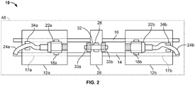
- a linear movement carriage system includes a pair of connector holders 18a and 18b located on carriages 12a and 12b.
- Carriages 12a and 12b are slidably mounted on a guide, such as guide rails 14 and 16. More specifically, each carriage includes a pair of bores, illustrated in phantom at 17a and 17b in Fig. 2 , through which the rails 14 and 16 pass.
- the guide may alternatively take the form of a channel formed in a base that supports the components of the device. The channel may be sized to slidably receive the carriages.
- the guide may take the form of a pair of rails that engage the sides of the carriages as they slide.
- the guide may be a track positioned on the base. Any other guide arrangement known in the art may alternatively be used.
- the carriages are provided with holders, such as, for example, clamps 18a and 18b that, as explained in greater detail below, are configured to removably receive a first needleless connector 22a and a second needleless connector 22b.
- Clamps 18a and 18b may be of any suitable construction but preferably are constructed from substantially rigid material with each including a pair of opposing, curved jaws that can flex so that a connector is received there between in a snap fit fashion.
- the clamps 18a and 18b may each include a pair of jaws or other gripping members that are motorized so as to spread apart and/or move together, to hold a connector, as a motor is energized. Any other clamping or holding arrangement known in the art could alternatively be used.
- tubing 24a and 24b are each part of, respectively, first and second medical fluid flow systems. Each is attached to one of the connectors 22a and 22b, respectively. The other ends of the tubing (not shown) may each terminate in a container for holding blood, medicine or other chemical, a disposal system, a processing system or any other component of a medical fluid flow system.
- a coupler holder 26 is positioned between the sliding carriages, preferably, but not exclusively, in a fixed fashion. Similar to carriages 12a and 12b, the coupler holder 26 may include a clamp 28 or other structure for holding a coupler, indicated in general at 32. Illustrated clamp 28 preferably is constructed from substantially rigid but somewhat flexible material and includes a pair of opposing, curved jaws or other gripping members so that the coupler is received there between in a snap fit fashion. Alternatively, the clamp 28 may include a pair of jaws that are motorized so as to spread apart and/or move together to hold the coupler as a motor is energized. Any other clamping or holding arrangement known in the art could alternatively be used.
- a tubing clamp 34a is provided on carriage 12a and a tubing claim 34b is provided on carriage 12b.
- the tubing clamps may be mounted in alternative locations, as long as they are capable of receiving tubing 24a and 24b and accommodating movement of the carriages.
- the tubing clamps 34a and 34b include facing jaws that are articulated by an actuator to engage or pinch and close off tubing 24a and 24b, respectively to fluid flow.
- the tubing clamp actuator may optionally include a solenoid so as to be electronically actuated. Examples of suitable tubing clamp actuators are provided in U.S. Patent Nos. 2,645,245 to Maisch ; 3,075,551 to Smith et al. ; 4,524,802 to Lawrence et al.
- coupler 32 preferably includes a body or housing having a middle portion 36 and opposite ends terminating in male Luer taper connectors 38a and 38b.
- a fluid flow path illustrated in phantom at 42 in Fig. 1 , extends through the coupler body and communicates with end ports at the end of each male Luer connector.
- the coupler may be of rigid plastic material and transparent to ultraviolet light, allowing ultraviolet exposure to sterilize the inner fluid flow path 42.
- Needleless connectors 22a and 22b each preferably includes a housing with a fluid flow path passing through it that communicates with the fluid flow path of the corresponding tubing.
- the fluid flow path of each connector preferably terminates at an end opening in a female Luer taper with a resilient valve positioned therein.
- the resilient valve seals the opening in a closed position and is compressible to an open position.
- suitable connectors include, but are not limited to, the connectors disclosed in U.S. Patent Nos. 5,047,021 to Utterberg ; 5,700,248 to Lopez ; 5,820,601 to Mayer ; 6,113,068 to Ryan ; 6,569,125 to Jepson et al. ; 7,998,122 to Lynn et al. ; 8,152,790 to Lopez et al. and 8,277,424 to Pan and U.S. Patent Application Publication No. US 2012/0089086 to Hokanson , the contents of each of which is hereby incorporated by reference
- the above components are mounted within a housing of any suitable shape, as indicated at 48 in Figs. 1-3 .
- the housing is constructed from a material that is substantially non-transmissive of ultraviolet light.
- the housing may have a lid or door 52 that covers an opening that provides access to the interior of the housing, and thus enables the connectors (22a and 22b of Figs. 1 and 2 ) and coupler (32 of Figs. 1 and 2 ) to be inserted and removed.
- the tubing attached to the connectors may be accommodated by slits or holes formed in opposite ends of the door or housing.
- the housing door may be pivotally mounted to the housing by a hinge 54 ( Fig. 3 ) or the door or lid may simply lift off of the housing or otherwise be secured to the housing in a removable or opening fashion using arrangements known in the art.
- the housing preferably includes an ultraviolet light reflecting interior surface which may, for example, be provided by an ultraviolet light reflective coating formed from, for example, aluminum.
- Tubing clamps 34a and 34b may optionally be positioned external to the housing 48.
- UV-C ultraviolet C
- UVGI ultraviolet germicidal irradiation
- the light source is used to irradiate the connectors and the coupler to sterilize them as they are connected.
- the slots or openings at the ends of the housing or door are preferably adapted to engage or optically seal around the tubes to prevent the escape of UV-C light. Examples of suitable ultraviolet housing designs are provided in the aforementioned U.S. Patent Nos. 4,500,788 to Kulin et al. ; 4,503,333 to Kulin et al. and 4,882,496 Bellotti et al. , the contents of each of which is hereby incorporated by reference.
- the coupler 32 ( Figs. 1 and 2 ) is made of ultraviolet light transparent or transmissive material to enable the flow path of the coupler (42 in Fig. 1 ) to be irradiated with the UV-C light.
- any rigid or at least semi-rigid UV-C light transparent material known in the art may be used to construct the coupler.
- suitable materials include polychlorotrifluoroethylene (PCTFE), quartz glass, cyclic olefin copolymer (COC polymer) or a formulation of polymethylmethacrylate.
- the ultraviolet light source intensity, the proximity of the light source to the coupler and connectors and the ultraviolet transmission capability of the coupler material all may be chosen to dose the interior surfaces of the coupler with about 5mJ/cm2 of UV-C light or greater.
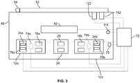
- FIG. 3 An example of a control system for operating the device 10 of Fig. 1 is presented in Fig. 3 .
- the carriages 12a and 12b are each provided with a drive system that includes a motor 74a and 74b, respectively.
- a controller 72 which may be a microprocessor or other electronic control device known in the art, electrically communicates with the light source 62, carriage motors 74a and 74b, a "Start" switch 75 and mechanisms 76a and 76b for actuating tubing clamps 34a and 34b, respectively.
- the user pushes the Start button (75 of Fig. 3 ).
- the controller (72 of Fig. 3 ) closes the tubing clamps 34a and 34b so that the flow paths of the tubing 24a and 24b upstream and downstream of the connectors are pinched closed. This reduces the risk of substantial leakage during the mating of the Luer connectors.
- the controller then activates the UV-C light source.
- the external vertical surfaces of the connector valves illustrated at 88a and 88b, are irradiated with UV-C light from light source 62. Since the needleless female Luer connectors 22a and 22b maintain sterility of the upstream and downstream connector and tubing fluid paths, only the connector valve exterior surfaces require UV-C light dosing.
- coupler 32 is irradiated with UV-C light.
- both the exterior surfaces of the coupler and the interior surface of the fluid flow path 42 therethrough are irradiated with the UV-C light. This results in assembly where the surfaces involved in making the connections, i.e. the exterior surface of the female Luer connectors and the exterior and interior surfaces of the coupler are reliably sterile without the need for meticulous manual swabbing.
- the connectors and coupler are irradiated for a period of time prior to being joined to ensure that enough dosage of UV-C light is delivered to adequately sterilize the inner and outer surfaces of the coupler and the exterior surfaces of the connector valves.
- the controller 72 activates the motors 74a and 74b of the carriages 12a and 12b so that the connectors 22a and 22b are moved towards the coupler 32. This movement continues until the connectors connectively engage or are joined to the coupler 32. As this occurs, the male Luer tapers of the coupler (38a and 38b of Fig. 1 ) move into the female Luer tapers and open the valves of the connectors 22a and 22b so that fluid flow paths of the connectors are in communication with the fluid flow path of the coupler. This step is indicated by block 102 of Fig. 4 and is illustrated in Fig. 5B . The movement continues until the male Luer surfaces are in tight engagement with the matching female Luer taper.
- carriage motors 74a and 74b may take the form of piezoelectric motors that are mounted to the carriages and that engage guide rails 14 and 16 ( Fig. 2 ) so as to move the carriages towards the coupler holder when energized.
- the motors 74a and 74b may be electric motors that are mounted to the housing or a base of the device independent of the carriages.
- a leadscrew may be attached to the driveshaft of each motor, with the leadscrew oriented with its longitudinal axis parallel to the direction of carriage travel, and each leadscrew may engage a threaded bore of a corresponding carriage so that the carriages are slid towards the coupler when each motor is energized.
- dosing or irradiation of the connectors and coupler by the UV-C light source 62 continues as the connectors 22a and 22b are joined to the coupler 32 to ensure a contamination-free connection.
- tubing 24a and/or 24b may be attached to a bag or other container holding blood, medicine or other fluid flow system component.
- Such containers may be pressurized or elevated so that liquid will flow through a corresponding connector 22a and/or 22b when the connector valve is opened.
- the closed configuration of the tubing clamps 34a and 34b prevents such liquid flow from occurring and prevents significant leakage from between the pinched portion of the tubing and a corresponding connector when the connector valve is opened by the coupler during the joining step.
- the UV-C light source 62 is deactivated by the system controller (see step 104 of Fig. 4 ).
- the intensity of the UV-C light source is preferably at a level that an irradiation time (including both prior to and after joining of the components) of 20 seconds or less is necessary to obtain satisfactory sterilization. Even more preferable is an irradiation time of less than 10 seconds.
- the controller next activates tubing clamp actuators (76a and 76b of Fig. 3 ) to open the tubing pinch clamps so that fluid flow through the fluid paths of the tubing, connectors and coupler occurs.
- the housing door may then be opened, and the connected coupler 32 and connectors 22a and 22b removed from the holders and housing, as illustrated in Fig. 5D .
- the joined coupler and connectors may remain in the housing (with the housing door closed) until the fluid transfer is complete.
- the tubing clamps 34a and 34b may again be closed and the UV-C light source 62 reactivated.
- the carriage drive system may then be activated by the controller so as to move the connector carriages away from the coupler holder towards the positions illustrated in Fig. 5A .
- the UV-C light source may then be deactivated.
- controller 72 may also communicate with a proximity sensor 112 as well as a warning light 114 that is positioned on, or close to, the device housing 48.
- Proximity sensor 112 is configured to detect the proximity of the housing door 52 when in the closed position (illustrated in Fig. 3 ) and to send a signal to the controller when the door is open.
- the controller performs the processing illustrated in Fig. 6 . More specifically, as indicated by step 116, the controller checks if the door of the housing is closed by monitoring the proximity sensor. If the proximity sensor indicates that the door is open, the controller deactivates the UV-C light source, as indicated by step 118. In addition, as indicated by step 120 the controller may illuminate the warning light (114 of Fig. 3 ) to further indicate that the door is ajar.
- the controller 72 may communicate with a locking mechanism 122 that prevents the housing door from being opened.
- the controller performs the processing illustrated in Fig. 7 .
- This processing is identical to the processing of Fig. 4 with the exception of the addition of steps 124 and 126.
- the user presses the "Start" button (75 of Fig. 3 ).
- the controller then activates the door locking mechanism (122 of Fig. 3 ), as indicated by step 124 of Fig. 7 .
- the device then continues to operate as described above until the tubing clamps are opened after the sterilization and connecting or joining steps.
- the controller deactivates the door locking mechanism so that the user may open the housing door and remove the joined connectors and coupler.
- the device may be provided with both the proximity sensor 112 and the door locking mechanism 122 of Fig. 3 so that the processing of both Figs. 6 and 7 is performed by the controller.
- the ultraviolet light bulb 62 (of Figs. 1 and 5A-5D ) may be replaced with light emitting diode emitters 132.
- the light emitting diode emitters 132 of Fig. 8 irradiate the ultraviolet transparent coupler 32 and connectors 22a and 22b with UV-C light in the manner described above with reference to Figs. 5A-5D .
- Such light emitting diode emitters offer advantages over the UV-C light bulb of Figs. 5A-5D in that some versions may be battery powered.
- the exterior surfaces of the distal ends of connectors 22a and 22b may be provided with threads 134a and 134b.
- ultraviolet light transparent coupler 32 may be provided with collars 136a and 136b that define annular spaces surrounding the ends of the coupler. The inner surfaces of the collar are provided with threads that mate with the threads 134a and 134b of the respective connectors.
- coupler holder 26 is preferably provided with a motor 138 and the coupler holder 140 is preferably adapted to rotate the coupler about an axis, indicated at 142, so that the coupler and connector threads engage.
- a drive mechanism 144 joins the motor 138 to the coupler holder 140 so that the coupler is rotated about the axis 142 when the motor is energized or activated. Suitable motors, holders and drive mechanisms are known in the art.
- the coupler may be provided with a pair of resilient lever arms, indicated in general at 154 and 156.
- the lever arms are joined to the housing 158 of the coupler by supports 162 and 164 that bisect elongated members 166 and 168.
- Elongated member 166 terminates in hooked ends 170a and 170b
- elongated member 168 terminates in hooked ends 172a and 172b.
- the two resilient lever arms may be constructed of the same material as the coupler and integrally formed with the coupler. While two resilient lever arms are illustrated, the coupler may alternatively feature a single resilient lever arm or more than two lever arms.
- connector 22b is provided with a collar 182
- connector 22a ( Fig. 1 ) is provided with a similar collar.
- the coupler may be provided with collars (similar as those illustrated in Fig. 8 ) and the connectors may each be provided with resilient lever arms that engage the coupler collars during the joining step ( Fig. 5B , block 102 of Fig. 4 ).
- the collars of the coupler do not need to be threaded.
- An example of a suitable connector is presented in U.S. Patent No. 5,688,254 to Lopez et al. , the contents of which are hereby incorporated by reference.
- the term "motor” as used to describe the above embodiments may be a mechanism that is manually actuated by the user, as opposed to a motor that is powered, for example, by electricity.
- the motor could include a crank and gears where the user turns the crank to rotate the gears so that the connector carriages 12a and 12b of Figs. 5A-5D are moved towards the coupler holder. Examples of such mechanisms are presented in the aforementioned U.S. Patent Nos. 4,500,788 to Kulin et al. and 4,882,496 Bellotti et al.
- the carriage system described above where both of the connector holders are moved towards the fixed coupler holder, is presented as an example only. Other arrangements where the connector and coupler holders are movable relative to each other may be used.
- one of the connector holders could be fixed with respect to the coupler holder and other connector holder movable towards the coupler holder.
- the coupler holder could simply be free to slide along the device guide (such as rails 14 and 16 of Fig. 2 ) with the movable connector holder contacting and pushing the coupler holder towards the fixed connector holder.
Landscapes
- Health & Medical Sciences (AREA)
- Engineering & Computer Science (AREA)
- Heart & Thoracic Surgery (AREA)
- General Engineering & Computer Science (AREA)
- Life Sciences & Earth Sciences (AREA)
- General Health & Medical Sciences (AREA)
- Epidemiology (AREA)
- Veterinary Medicine (AREA)
- Public Health (AREA)
- Animal Behavior & Ethology (AREA)
- Pulmonology (AREA)
- Anesthesiology (AREA)
- Hematology (AREA)
- Biomedical Technology (AREA)
- Mechanical Engineering (AREA)
- Apparatus For Disinfection Or Sterilisation (AREA)
- Physical Water Treatments (AREA)
- Infusion, Injection, And Reservoir Apparatuses (AREA)
Abstract
Description
- This application claims the benefit of
U.S. Provisional Application No 62/304,423, filed March 7, 2016 - The present disclosure relates generally to needleless connectors for medical fluid flow systems and, in particular, to a system and method for creating sterile connections using such connectors.
- Medical fluid flow tubing systems often employ needleless connectors, such as Luer connectors, to reduce the risk of needle stick for employees and to ensure that sealed connections are made. The female half of two mating connectors typically has a septum or silicon valve that covers, or is positioned within, a Luer tapered opening that communicates with a fluid flow path. The male connector features a tapered member having a Luer taper that corresponds to the Luer taper of the female connector with a fluid flow passage therein that communicates with an opening at the tip or distal end of the tapered male member.
- Current common practice for making fluid flow connections using needleless connectors is an aseptic process where the exterior surface of the valve, diaphragm or septum of the female connector is manually swabbed with antiseptic prior to insertion of the male connector (which compresses and opens the valve). Manual swabbing requires increased vigilance and discipline by the healthcare professionals attending to a patient or carrying out the process in question. Failure to follow rigorous procedures can potentially result in microorganisms or other contaminants being inadvertently introduced into the fluid path. Even for specialized care in controlled environments, training and existing connector design cannot completely eliminate the possibility of human error for contamination when such a process is used.
- Other solutions for connecting medical fluid flow tubing recognize that irradiation of connectors with ultraviolet light provides an antibacterial effect on, or sterilization of, the irradiated connector surfaces. Examples of such systems and devices are presented in
U.S. Patent Nos. to 4,500,788 to Kulin et al. ;4,503,333 to Kulin et al. and4,883,496 to Bellotti et al. The systems and devices of these references, however, are intended for use in specialized settings with connectors of special design. - There are a variety of other sterile connection systems for joining fluid flow tubing with specialized connector systems or relatively expensive disposable components. For example, a tubing connector that employs heated wafers is known as the SCD® IIB sterile tubing welder available from Terumo BCT of Lakewood, Colorado, and is described in
U.S. Patent No. 4,753,697 . Other sterile connection systems may be found in U.S. Patent Application Publication No.US 2014/0077488 ;U.S. Patent No. 4,157,723 ; andU.S. Patent No. 5,009,446 . - Accordingly, there continues to be a desire to develop advanced systems and methods for creating sterile connections.
- There are several aspects of the present subject matter which may be embodied separately or together in the devices and systems described and claimed below. These aspects may be employed alone or in combination with other aspects of the subject matter described herein, and the description of these aspects together is not intended to preclude the use of these aspects separately or the claiming of such aspects separately or in different combinations as set forth in the claims appended hereto.
- In one aspect, a device is provided for connecting first and second medical fluid flow systems, where each includes, respectively, first and second connectors connectable to a coupler. The device includes a housing that is substantially non-transmissive of ultraviolet light. A linear movement carriage system is positioned within the housing and includes a first connector holder configured to hold the first connector, a second connector holder configured to hold the second connector and a coupler holder configured to hold the coupler. The coupler holder is positioned substantially between the first and second connector holders. The first and second connector holders and the coupler holder are relatively moveable between separated and joined configurations. In the separated configuration, the first and second connector holders and the coupler holder are located in relatively spaced apart positions so that first and second connectors held by the first and second connector holders are spaced apart from a coupler held by the coupler holder. In the joined configuration, the first and second connector holders are positioned more closely to the coupler holder than when in the separated configuration so that the first and second connectors held by the first and second connector holders engage the coupler held by the coupler holder. An ultraviolet light source is positioned in the housing so as to irradiate first and second connectors held by the first and second connector holders and a coupler held by the coupler holder when the carriage system is in the separated configuration. A drive system includes a first motor operatively connected to at least one of the first and second connector holders so as to transition the first and second connector holders and the coupler holder between the separated and the joined configurations.
- In another aspect, a method is provided for connecting first and second medical fluid flow systems, each of which includes, respectively, first and second connectors connectable to a coupler. The method includes positioning the coupler between the first and second connectors in a spaced-apart position within a substantially ultraviolet non-transmissive housing. The coupler and the first and second connectors are irradiated with ultraviolet light. The first and second connectors and the coupler are relatively moved so that the first and second connectors connectably engage the coupler. The connected first and second connectors and the coupler are removed from the housing.
- In yet another aspect, a coupler is provided for coupling together first and second needleless connectors associated with first and second medical fluid flow systems, where each of the needleless connectors includes a housing with a fluid flow path there through terminating at an end opening in a female Luer taper. A resilient valve is disposed within the opening and seals the opening in a first closed position and is compressible to a second open position. The coupler includes an ultraviolet light transmissive housing including opposed male Luer connectors. A fluid flow path extends through the housing and terminates in an end port of each of the male Luer connectors. Each of the opposed male Luer connectors can be connected to the female Luer taper of one of the needleless connectors so as to compress the resilient valve therein to open a flow path between the first and second fluid flow systems through the respective needleless connectors and the coupler.
-
-
Fig. 1 is a side elevational view of an embodiment of the system of the disclosure with the two connectors and coupler just prior to loading; -
Fig. 2 is a top plan view of the system ofFig. 1 with the ultraviolet light source omitted for clarity; -
Fig. 3 is a schematic of the components and the control system of an embodiment of the system of the disclosure; -
Fig. 4 is a flow diagram illustrating processing performed by the control system ofFig. 3 in accordance with an embodiment of the method of the disclosure; -
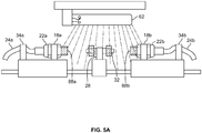
Fig. 5A shows the system ofFig. 3 prior to connecting or joining the two loaded connectors to the loaded coupler and during irradiation by ultraviolet light; -
Fig. 5B shows the system ofFig. 5A after the two connectors have been joined to the coupler and during continued irradiation by ultraviolet light; -
Fig. 5C shows the system ofFig. 5B after the irradiation by ultraviolet light has been ceased; -
Fig. 5D shows the system ofFig. 5C with the joined connectors and coupler being removed; -
Fig. 6 is a flow diagram illustrating processing performed by the control system ofFig. 3 to monitor the configuration of the housing door; -
Fig. 7 is a flow diagram illustrating processing performed by the control system ofFig. 3 in accordance with another embodiment of the method of the disclosure; -
Fig. 8 is a side elevational view of an alternative embodiment of the system of the disclosure where ultraviolet light emitting diode emitters are used; -
Fig. 9A is an enlarged perspective view of an alternative embodiment of the coupler and one of the connectors prior to being joined; -
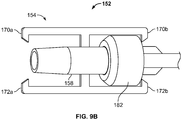
Fig. 9B is a perspective view of the coupler and connector ofFig. 9A after being joined. - One embodiment of the device or system of the disclosure is indicated in general at 10 in
Figs. 1 and2 . A linear movement carriage system includes a pair ofconnector holders carriages Carriages guide rails Fig. 2 , through which therails - The carriages are provided with holders, such as, for example, clamps 18a and 18b that, as explained in greater detail below, are configured to removably receive a first
needleless connector 22a and a secondneedleless connector 22b.Clamps clamps - As illustrated,
tubing connectors - A
coupler holder 26 is positioned between the sliding carriages, preferably, but not exclusively, in a fixed fashion. Similar tocarriages coupler holder 26 may include aclamp 28 or other structure for holding a coupler, indicated in general at 32. Illustratedclamp 28 preferably is constructed from substantially rigid but somewhat flexible material and includes a pair of opposing, curved jaws or other gripping members so that the coupler is received there between in a snap fit fashion. Alternatively, theclamp 28 may include a pair of jaws that are motorized so as to spread apart and/or move together to hold the coupler as a motor is energized. Any other clamping or holding arrangement known in the art could alternatively be used. - A
tubing clamp 34a is provided oncarriage 12a and atubing claim 34b is provided oncarriage 12b. The tubing clamps may be mounted in alternative locations, as long as they are capable of receivingtubing tubing U.S. Patent Nos. 2,645,245 to Maisch ;3,075,551 to Smith et al. ;4,524,802 to Lawrence et al. ;5,188,334 to Yoshii et al. ; and9,022,344 to Manzella Jr. et al. - With reference to
Fig. 1 ,coupler 32 preferably includes a body or housing having amiddle portion 36 and opposite ends terminating in maleLuer taper connectors Fig. 1 , extends through the coupler body and communicates with end ports at the end of each male Luer connector. The coupler may be of rigid plastic material and transparent to ultraviolet light, allowing ultraviolet exposure to sterilize the innerfluid flow path 42. -
Needleless connectors U.S. Patent Nos. 5,047,021 to Utterberg ;5,700,248 to Lopez ;5,820,601 to Mayer ;6,113,068 to Ryan ;6,569,125 to Jepson et al. ;7,998,122 to Lynn et al. ;8,152,790 to Lopez et al. and8,277,424 to Pan and U.S. Patent Application Publication No.US 2012/0089086 to Hokanson , the contents of each of which is hereby incorporated by reference. - The above components are mounted within a housing of any suitable shape, as indicated at 48 in
Figs. 1-3 . The housing is constructed from a material that is substantially non-transmissive of ultraviolet light. As illustrated inFig. 3 , the housing may have a lid ordoor 52 that covers an opening that provides access to the interior of the housing, and thus enables the connectors (22a and 22b ofFigs. 1 and2 ) and coupler (32 ofFigs. 1 and2 ) to be inserted and removed. The tubing attached to the connectors may be accommodated by slits or holes formed in opposite ends of the door or housing. The housing door may be pivotally mounted to the housing by a hinge 54 (Fig. 3 ) or the door or lid may simply lift off of the housing or otherwise be secured to the housing in a removable or opening fashion using arrangements known in the art. - The housing preferably includes an ultraviolet light reflecting interior surface which may, for example, be provided by an ultraviolet light reflective coating formed from, for example, aluminum.
- Tubing clamps 34a and 34b may optionally be positioned external to the
housing 48. - An ultraviolet light source in the form of an
ultraviolet light bulb 62 is also positioned within the housing, as illustrated inFigs. 1 and3 . The ultraviolet light source preferably provides ultraviolet C (UV-C) light, which is known for use in ultraviolet germicidal irradiation (UVGI) systems to provide short-wavelength ultraviolet light that kills or inactivates microorganisms. As an example only, the light source preferably emits ultraviolet light with wavelengths in the range of 250-280 nm. - As will be described in greater detail below, the light source is used to irradiate the connectors and the coupler to sterilize them as they are connected. In addition to the housing being made from a material that is substantially non-transmissive of ultraviolet light, the slots or openings at the ends of the housing or door are preferably adapted to engage or optically seal around the tubes to prevent the escape of UV-C light. Examples of suitable ultraviolet housing designs are provided in the aforementioned
U.S. Patent Nos. 4,500,788 to Kulin et al. ;4,503,333 to Kulin et al. and4,882,496 Bellotti et al. , the contents of each of which is hereby incorporated by reference. - The coupler 32 (
Figs. 1 and2 ) is made of ultraviolet light transparent or transmissive material to enable the flow path of the coupler (42 inFig. 1 ) to be irradiated with the UV-C light. Basically any rigid or at least semi-rigid UV-C light transparent material known in the art may be used to construct the coupler. Examples of suitable materials include polychlorotrifluoroethylene (PCTFE), quartz glass, cyclic olefin copolymer (COC polymer) or a formulation of polymethylmethacrylate. - The ultraviolet light source intensity, the proximity of the light source to the coupler and connectors and the ultraviolet transmission capability of the coupler material all may be chosen to dose the interior surfaces of the coupler with about 5mJ/cm2 of UV-C light or greater.
- An example of a control system for operating the
device 10 ofFig. 1 is presented inFig. 3 . Thecarriages motor controller 72, which may be a microprocessor or other electronic control device known in the art, electrically communicates with thelight source 62,carriage motors switch 75 andmechanisms - Operation of the device will now be described with reference to
Figs. 3 ,4 and5A-5D . After the housing door is opened, theconnectors C transmissive coupler 32 is placed incoupler holder clamp 28, as illustrated inFig. 5A . In addition,tubing - To initiate the sterilization and connection process, as indicated by
block 82 ofFig. 4 , the user pushes the Start button (75 ofFig. 3 ). In response, as indicated byblock 84 ofFig. 4 , the controller (72 ofFig. 3 ) closes the tubing clamps 34a and 34b so that the flow paths of thetubing - As indicated at
step 86 ofFig. 4 , the controller then activates the UV-C light source. As a result, with reference toFig. 5A , the external vertical surfaces of the connector valves, illustrated at 88a and 88b, are irradiated with UV-C light fromlight source 62. Since the needlelessfemale Luer connectors - Furthermore, as illustrated in
Fig. 5A ,coupler 32 is irradiated with UV-C light. As a result of the construction of the coupler from UV-C light transmissive material, both the exterior surfaces of the coupler and the interior surface of thefluid flow path 42 therethrough are irradiated with the UV-C light. This results in assembly where the surfaces involved in making the connections, i.e. the exterior surface of the female Luer connectors and the exterior and interior surfaces of the coupler are reliably sterile without the need for meticulous manual swabbing. - The connectors and coupler are irradiated for a period of time prior to being joined to ensure that enough dosage of UV-C light is delivered to adequately sterilize the inner and outer surfaces of the coupler and the exterior surfaces of the connector valves.
- Next, with reference to
Fig. 3 , thecontroller 72 activates themotors carriages connectors coupler 32. This movement continues until the connectors connectively engage or are joined to thecoupler 32. As this occurs, the male Luer tapers of the coupler (38a and 38b ofFig. 1 ) move into the female Luer tapers and open the valves of theconnectors block 102 ofFig. 4 and is illustrated inFig. 5B . The movement continues until the male Luer surfaces are in tight engagement with the matching female Luer taper. - A variety of electromechanical systems known in the art may be used to move the
carriages carriage motors guide rails 14 and 16 (Fig. 2 ) so as to move the carriages towards the coupler holder when energized. As another example, themotors - As illustrated in
Fig. 5B , dosing or irradiation of the connectors and coupler by the UV-C light source 62 continues as theconnectors coupler 32 to ensure a contamination-free connection. - As noted above,
tubing 24a and/or 24b may be attached to a bag or other container holding blood, medicine or other fluid flow system component. Such containers may be pressurized or elevated so that liquid will flow through acorresponding connector 22a and/or 22b when the connector valve is opened. The closed configuration of the tubing clamps 34a and 34b prevents such liquid flow from occurring and prevents significant leakage from between the pinched portion of the tubing and a corresponding connector when the connector valve is opened by the coupler during the joining step. - Turning to
Fig. 5C , after theconnectors coupler 32, the UV-C light source 62 is deactivated by the system controller (seestep 104 ofFig. 4 ). The intensity of the UV-C light source is preferably at a level that an irradiation time (including both prior to and after joining of the components) of 20 seconds or less is necessary to obtain satisfactory sterilization. Even more preferable is an irradiation time of less than 10 seconds. - As illustrated at
step 106 ofFig. 4 , the controller next activates tubing clamp actuators (76a and 76b ofFig. 3 ) to open the tubing pinch clamps so that fluid flow through the fluid paths of the tubing, connectors and coupler occurs. - The housing door may then be opened, and the
connected coupler 32 andconnectors Fig. 5D . - Alternatively, for connections between the coupler and connectors that may be temporary, the joined coupler and connectors may remain in the housing (with the housing door closed) until the fluid transfer is complete. In the event that the user wishes to preserve the sterility of the connector and coupler components and the associated fluid pathway for further use, after fluid transfer is complete, the tubing clamps 34a and 34b may again be closed and the UV-
C light source 62 reactivated. The carriage drive system may then be activated by the controller so as to move the connector carriages away from the coupler holder towards the positions illustrated inFig. 5A . The UV-C light source may then be deactivated. Such a procedure and embodiment enables reconnecton of the components at a later time so as to make the coupler and connectors available for multiple uses. - As illustrated in
Fig. 3 ,controller 72 may also communicate with aproximity sensor 112 as well as awarning light 114 that is positioned on, or close to, thedevice housing 48.Proximity sensor 112 is configured to detect the proximity of thehousing door 52 when in the closed position (illustrated inFig. 3 ) and to send a signal to the controller when the door is open. In this regard, the controller performs the processing illustrated inFig. 6 . More specifically, as indicated bystep 116, the controller checks if the door of the housing is closed by monitoring the proximity sensor. If the proximity sensor indicates that the door is open, the controller deactivates the UV-C light source, as indicated bystep 118. In addition, as indicated bystep 120 the controller may illuminate the warning light (114 ofFig. 3 ) to further indicate that the door is ajar. - In an alternative embodiment, with reference to
Fig. 3 , thecontroller 72 may communicate with alocking mechanism 122 that prevents the housing door from being opened. In such an embodiment, the controller performs the processing illustrated inFig. 7 . This processing is identical to the processing ofFig. 4 with the exception of the addition ofsteps Fig. 4 , after the two connectors and coupler have been loaded into the holders within the device housing, and the door closed, the user presses the "Start" button (75 ofFig. 3 ). The controller then activates the door locking mechanism (122 ofFig. 3 ), as indicated bystep 124 ofFig. 7 . The device then continues to operate as described above until the tubing clamps are opened after the sterilization and connecting or joining steps. After the tubing clamps are opened, as indicated atstep 126 inFig. 7 , the controller deactivates the door locking mechanism so that the user may open the housing door and remove the joined connectors and coupler. - In still another embodiment, the device may be provided with both the
proximity sensor 112 and thedoor locking mechanism 122 ofFig. 3 so that the processing of bothFigs. 6 and7 is performed by the controller. - In a further alternative embodiment, illustrated in
Fig. 8 , the ultraviolet light bulb 62 (ofFigs. 1 and5A-5D ) may be replaced with light emittingdiode emitters 132. The light emittingdiode emitters 132 ofFig. 8 irradiate the ultraviolettransparent coupler 32 andconnectors Figs. 5A-5D . Such light emitting diode emitters offer advantages over the UV-C light bulb ofFigs. 5A-5D in that some versions may be battery powered. - With continued reference to
Fig. 8 , the exterior surfaces of the distal ends ofconnectors threads transparent coupler 32 may be provided withcollars threads coupler holder 26 is preferably provided with amotor 138 and thecoupler holder 140 is preferably adapted to rotate the coupler about an axis, indicated at 142, so that the coupler and connector threads engage. Adrive mechanism 144 joins themotor 138 to thecoupler holder 140 so that the coupler is rotated about theaxis 142 when the motor is energized or activated. Suitable motors, holders and drive mechanisms are known in the art. - In an alternative embodiment, with reference to
Figs. 9A and9B , the coupler, indicated in general at 152, may be provided with a pair of resilient lever arms, indicated in general at 154 and 156. The lever arms are joined to thehousing 158 of the coupler bysupports elongated members Elongated member 166 terminates in hooked ends 170a and 170b, whileelongated member 168 terminates in hooked ends 172a and 172b. As an example only, the two resilient lever arms may be constructed of the same material as the coupler and integrally formed with the coupler. While two resilient lever arms are illustrated, the coupler may alternatively feature a single resilient lever arm or more than two lever arms. With reference toFigs. 9A and9B ,connector 22b is provided with acollar 182, whileconnector 22a (Fig. 1 ) is provided with a similar collar. - As illustrated in
Figs. 9A and9B , during the joining step (Fig. 5B , block 102 ofFig. 4 ), thecollar 182 ofconnector 22b is received and engaged by the hooked ends 170b and 172b of the resilient lever arms. The hooked ends 170a and 172a receive and engage the collar ofconnector 22a (Fig. 1 ) in a similar fashion. As a result, the connectors and coupler are joined in a more robust fashion so as to prevent decoupling if the joined components are removed from the device housing. - In another alternative embodiment, the coupler may be provided with collars (similar as those illustrated in
Fig. 8 ) and the connectors may each be provided with resilient lever arms that engage the coupler collars during the joining step (Fig. 5B , block 102 ofFig. 4 ). In such an embodiment, the collars of the coupler do not need to be threaded. An example of a suitable connector is presented inU.S. Patent No. 5,688,254 to Lopez et al. , the contents of which are hereby incorporated by reference. - It should be noted that the term "motor" as used to describe the above embodiments may be a mechanism that is manually actuated by the user, as opposed to a motor that is powered, for example, by electricity. For example, the motor could include a crank and gears where the user turns the crank to rotate the gears so that the
connector carriages Figs. 5A-5D are moved towards the coupler holder. Examples of such mechanisms are presented in the aforementionedU.S. Patent Nos. 4,500,788 to Kulin et al. and4,882,496 Bellotti et al. - It should be further noted that the carriage system described above, where both of the connector holders are moved towards the fixed coupler holder, is presented as an example only. Other arrangements where the connector and coupler holders are movable relative to each other may be used. In an alternative embodiment, for example, one of the connector holders could be fixed with respect to the coupler holder and other connector holder movable towards the coupler holder. In such an arrangement, the coupler holder could simply be free to slide along the device guide (such as
rails Fig. 2 ) with the movable connector holder contacting and pushing the coupler holder towards the fixed connector holder. - The present subject includes various aspects, which may be in addition to those set forth above, such as:
- Aspect 1. A device for connecting first and second medical fluid flow systems, each of which includes, respectively, first and second connectors connectable to a coupler, the device comprising: a housing that is substantially non-transmissive of ultraviolet light; a linear movement carriage system positioned within the housing and including a first connector holder configured to hold the first connector, a second connector holder configured to hold the second connector and a coupler holder configured to hold the coupler, the coupler holder positioned substantially between the first and second connector holders, the first and second connector holders and the coupler holder being relatively moveable between: a separated configuration where the first and second connector holders and the coupler holder are located in relatively spaced apart positions so that first and second connectors held by the first and second connector holders are spaced apart from a coupler held by the coupler holder; and a joined configuration where the first and second connector holders are positioned more closely to the coupler holder than when in the separated configuration so that the first and second connectors held by the first and second connector holders engage the coupler held by the coupler holder; an ultraviolet light source positioned in the housing so as to irradiate first and second connectors held by the first and second connector holders and a coupler held by the coupler holder when the carriage system is in the separated configuration; and a drive system including a first motor operatively connected to at least one of the first and second connector holders so as to transition the first and second connector holders and the coupler holder between the separated and the joined configurations.
- Aspect 2. The device of Aspect 1, wherein the drive system is electromechanical.
- Aspect 3. The device of Aspect 1 or 2, wherein the carriage system includes a guide with respect to which the first connector holder is moveably positioned and the first motor is operatively associated with the first connector holder and the guide so as to move the first connector holder along the guide as the carriage system is transitioned between the separated and joined configurations when the first motor is actuated.
- Aspect 4. The device of any one of Aspects 1-3, further comprising a leadscrew attached to the first motor so that the leadscrew is rotated about a longitudinal axis when the first motor is actuated, said leadscrew engaging the first connector holder so that the first connector holder is moved when the first motor rotates the leadscrew.
- Aspect 5. The device of any one of Aspects 1-4 further comprising a first tubing clamp adapted to receive a first tubing communicating with the first connector, said first tubing clamp being operable to block fluid flow through the first tubing in a closed configuration and to allow fluid flow through the first tubing when in an open configuration.
- Aspect 6. The device of Aspect 5 further comprising a first tubing clamp actuator operatively associated with the first tubing clamp to move the first tubing clamp between the closed and open configurations.
- Aspect 7. The device of Aspects 5 or 6 further comprising a second tubing clamp adapted to receive a second tubing communicating with the second connector, said second tubing clamp being operable to block fluid flow through the second tubing in a closed configuration and to allow fluid flow through the second tubing when in an open configuration.
- Aspect 8. The device of Aspect 7 further comprising a second clamp actuator operatively associated with the second tubing clamp to move the second tubing clamp between the closed and open configurations.
- Aspect 9. The device of Aspect 1 wherein the housing defines an interior and further comprising a door moveable between an open configuration, where the interior of the housing may be accessed, and a closed configuration, where the interior of the housing cannot be accessed.
-
Aspect 10. The device of Aspect 9 further comprising a proximity sensor operable to detect whether the door is in the closed configuration and a controller in communication with the proximity sensor and the ultraviolet light source, said controller adapted to allow power from a power source to the ultraviolet light source when the proximity sensor indicates that the door is in the closed configuration and to prevent power to the light source when the door is in the open configuration. - Aspect 11. The device of any one of Aspects 1-10 wherein the drive system further includes a second motor operatively connected to the second connector holder so as to move the second connector holder as the carriage system is transitioned between the separated and the joined configurations.
- Aspect 12. The device of Aspect 11 wherein the coupler holder is in a fixed position with respect to the moveable first and second connector holders.
- Aspect 13. A method for connecting first and second medical fluid flow systems, each of which includes, respectively, first and second connectors connectable to a coupler, the method comprising the steps of: positioning the coupler between the first and second connectors in a spaced-apart position within a substantially ultraviolet non-transmissive housing; irradiating the coupler and the first and second connectors with ultraviolet light; relatively moving the first and second connectors and the coupler so that the first and second connectors connectably engage the coupler; and removing the connected first and second connectors and coupler from the housing.
-
Aspect 14. The method of Aspect 13 wherein the step of relatively moving includes rotating the coupler relative to the first and second connectors. - Aspect 15. The method of
Aspect 13 or 14 further comprising closing a first tubing communicating with the first connector and closing a second tubing communicating with the second connector so that no fluid is able to flow through the tubing prior to irradiating and opening the first and second tubing so that fluid is able to flow through each after the first and second connectors are connectably engaged with the coupler. -
Aspect 16. The method of any one of Aspects 13-15 wherein the relatively moving includes moving the first and second connector holders toward the coupler holder. - Aspect 17. The method of any one of Aspects 13-16 wherein the coupler has an interior passage and is substantially transmissive of ultraviolet light so that the interior passage of the coupler is irradiated with ultraviolet light during the irradiating
- Aspect 18. The method of any one of Aspects 13-16 wherein the ultraviolet light is ultraviolet C.
- Aspect 19. A coupler for coupling together first and second needleless connectors associated with first and second medical fluid flow systems, each of which needleless connectors comprises a housing with a fluid flow path there through terminating at an end opening in a female Luer taper and a resilient valve disposed within and sealing the opening in a first closed position and being compressible to a second open position, the coupler comprising: an ultraviolet light transmissive housing including opposed male Luer connectors, and a fluid flow path extending through the housing and terminating in an end port of each of the male Luer connectors, whereby each of the opposed male Luer connectors can be connected to the female Luer taper of one of the needleless connectors so as to compress the resilient valve therein to open a flow path between the first and second fluid flow systems through the respective needleless connectors and the coupler.
- Aspect 20. The coupler of Aspect 19 including a threaded collar associated with each male Luer connector for threadedly engaging a respective needleless connector connected thereto.
- Aspect 21. The coupler of Aspect 19 including a resilient lever arm connected to the housing and having a pair of hooked ends for engaging collars of needleless connectors connected to the male Luer connectors.
- While the preferred embodiments of the disclosure have been shown and described, it will be apparent to those skilled in the art that changes and modifications may be made therein without departing from the spirit of the disclosure, the scope of which is defined by the following claims.
Claims (15)
- A device for connecting first and second medical fluid flow systems, each of which includes, respectively, first and second connectors connectable to a coupler, the device comprising:a. a housing that is substantially non-transmissive of ultraviolet light;b. a linear movement carriage system positioned within the housing and including a first connector holder configured to hold the first connector, a second connector holder configured to hold the second connector and a coupler holder configured to hold the coupler, said coupler holder positioned substantially between the first and second connector holders, the first and second connector holders and the coupler holder being relatively moveable between:i) a separated configuration where the first and second connector holders and the coupler holder are located in relatively spaced apart positions so that first and second connectors held by the first and second connector holders are spaced apart from a coupler held by the coupler holder; andii) a joined configuration where the first and second connector holders are positioned more closely to the coupler holder than when in the separated configuration so that the first and second connectors held by the first and second connector holders engage the coupler held by the coupler holder;c. an ultraviolet light source positioned in the housing so as to irradiate first and second connectors held by the first and second connector holders and a coupler held by the coupler holder when the carriage system is in the separated configuration; andd. a drive system including a first motor operatively connected to at least one of the first and second connector holders so as to transition the first and second connector holders and the coupler holder between the separated and the joined configurations.
- The device of claim 1 wherein the carriage system includes a guide with respect to which the first connector holder is moveably positioned and the first motor is operatively associated with the first connector holder and the guide so as to move the first connector holder along the guide as the carriage system is transitioned between the separated and joined configurations when the first motor is actuated.
- The device of claim 1 or 2 further comprising a leadscrew attached to the first motor so that the leadscrew is rotated about a longitudinal axis when the first motor is actuated, said leadscrew engaging the first connector holder so that the first connector holder is moved when the first motor rotates the leadscrew.
- The device of any one of claims 1-3 further comprising:e. a first tubing clamp adapted to receive a first tubing communicating with the first connector, said first tubing clamp being operable to block fluid flow through the first tubing in a closed configuration and to allow fluid flow through the first tubing when in an open configuration; andf. a second tubing clamp adapted to receive a second tubing communicating with the second connector, said second tubing clamp being operable to block fluid flow through the second tubing in a closed configuration and to allow fluid flow through the second tubing when in an open configuration.
- The device of any one of claims 1-4 wherein the housing defines an interior and further comprising a door moveable between an open configuration, where the interior of the housing may be accessed, and a closed configuration, where the interior of the housing cannot be accessed, a proximity sensor operable to detect whether the door is in the closed configuration and a controller in communication with the proximity sensor and the ultraviolet light source, said controller adapted to allow power from a power source to the ultraviolet light source when the proximity sensor indicates that the door is in the closed configuration and to prevent power to the light source when the door is in the open configuration.
- The device of any one of claims 1-10 wherein the drive system further includes a second motor operatively connected to the second connector holder so as to move the second connector holder as the carriage system is transitioned between the separated and the joined configurations.
- The device of claim 6 wherein the coupler holder is in a fixed position with respect to the moveable first and second connector holders.
- A method for connecting first and second medical fluid flow systems, each of which includes, respectively, first and second connectors connectable to a coupler, the method comprising the steps of:a. positioning the coupler between the first and second connectors in a spaced-apart position within a substantially ultraviolet non-transmissive housing;b. irradiating the coupler and the first and second connectors with ultraviolet light;c. relatively moving the first and second connectors and the coupler so that the first and second connectors connectably engage the coupler; andd. removing the connected first and second connectors and coupler from the housing.
- The method of claim 8 wherein the step of relatively moving includes rotating the coupler relative to the first and second connectors.
- The method of claim 8 or 9 further comprising closing a first tubing communicating with the first connector and closing a second tubing communicating with the second connector so that no fluid is able to flow through the tubing prior to irradiating and opening the first and second tubing so that fluid is able to flow through each after the first and second connectors are connectably engaged with the coupler.
- The method of any one of claims 8-10 wherein the relatively moving includes moving the first and second connector holders toward the coupler holder.
- The method of any one of claims 8-11 wherein the ultraviolet light is ultraviolet C.
- A coupler for coupling together first and second needleless connectors associated with first and second medical fluid flow systems, each of which needleless connectors comprises a housing with a fluid flow path there through terminating at an end opening in a female Luer taper and a resilient valve disposed within and sealing the opening in a first closed position and being compressible to a second open position, the coupler comprising:a. an ultraviolet light transmissive housing including opposed male Luer connectors, and a fluid flow path extending through the housing and terminating in an end port of each of the male Luer connectors,b. whereby each of the opposed male Luer connectors can be connected to the female Luer taper of one of the needleless connectors so as to compress the resilient valve therein to open a flow path between the first and second fluid flow systems through the respective needleless connectors and the coupler.
- The coupler of claim 13 including a threaded collar associated with each male Luer connector for threadedly engaging a respective needleless connector connected thereto.
- The coupler of claim 13 including a resilient lever arm connected to the housing and having a pair of hooked ends for engaging collars of needleless connectors connected to the male Luer connectors.
Applications Claiming Priority (1)
| Application Number | Priority Date | Filing Date | Title |
|---|---|---|---|
| US201662304423P | 2016-03-07 | 2016-03-07 |
Publications (2)
| Publication Number | Publication Date |
|---|---|
| EP3216487A1 true EP3216487A1 (en) | 2017-09-13 |
| EP3216487B1 EP3216487B1 (en) | 2020-05-06 |
Family
ID=58227963
Family Applications (1)
| Application Number | Title | Priority Date | Filing Date |
|---|---|---|---|
| EP17159027.6A Active EP3216487B1 (en) | 2016-03-07 | 2017-03-03 | System and method for creating sterile connections using ultraviolet light |
Country Status (2)
| Country | Link |
|---|---|
| US (1) | US10525249B2 (en) |
| EP (1) | EP3216487B1 (en) |
Cited By (1)
| Publication number | Priority date | Publication date | Assignee | Title |
|---|---|---|---|---|
| EP3501594A3 (en) * | 2017-12-21 | 2019-07-31 | Fenwal, Inc. | System and method of sterilely connecting fluid pathways |
Families Citing this family (7)
| Publication number | Priority date | Publication date | Assignee | Title |
|---|---|---|---|---|
| JP7190044B2 (en) * | 2018-12-03 | 2022-12-14 | セクレタリー・デパートメント・オブ・バイオテクノロジー | Devices for preventing catheter-related urinary tract infections |
| EP3888734A1 (en) | 2020-04-02 | 2021-10-06 | Fenwal, Inc. | Reversible sterile connection system |
| WO2022047023A1 (en) | 2020-08-27 | 2022-03-03 | Colder Products Company | Fluid couplings |
| JP2022041240A (en) * | 2020-08-31 | 2022-03-11 | トヨタ自動車株式会社 | Sterilization device for boarding handrail |
| US20240252805A1 (en) * | 2021-06-02 | 2024-08-01 | Geoffrey L. Hodge | Connection interface for sterile connection and fluid transfer |
| AU2022325789A1 (en) * | 2021-08-11 | 2024-01-04 | Geoffrey L. Hodge | Systems and methods for manufacturing cells |
| AU2023228673A1 (en) * | 2022-03-02 | 2024-09-12 | University Of Washington | Medical tubing breakaway device and methods of use |
Citations (27)
| Publication number | Priority date | Publication date | Assignee | Title |
|---|---|---|---|---|
| US2645245A (en) | 1951-08-29 | 1953-07-14 | Maisch Oliver | Pipette control means |
| US3075551A (en) | 1957-03-11 | 1963-01-29 | Gorman Rupp Ind Inc | Control valve for fluid flow system |
| US4157723A (en) | 1977-10-19 | 1979-06-12 | Baxter Travenol Laboratories, Inc. | Method of forming a connection between two sealed conduits using radiant energy |
| US4214586A (en) * | 1978-11-30 | 1980-07-29 | Ethicon, Inc. | Anastomotic coupling device |
| US4500788A (en) | 1983-08-19 | 1985-02-19 | Baxter Travenol Laboratories, Inc. | Device for providing antibacterial radiation |
| US4503333A (en) | 1981-06-05 | 1985-03-05 | Baxter Travenol Laboratories | Antimicrobial ultraviolet irradiation of connector for continuous ambulatory peritoneal dialysis |
| WO1985000979A1 (en) * | 1983-08-19 | 1985-03-14 | Baxter Travenol Laboratories, Inc. | Device for providing antibacterial radiation |
| US4524802A (en) | 1984-10-01 | 1985-06-25 | Bio-Chem Valve Corp. | Pinch valve |
| US4753697A (en) | 1987-02-24 | 1988-06-28 | Denco, Inc. | Total-containment sterile process and system |
| US4882496A (en) | 1988-04-29 | 1989-11-21 | Baxter International Inc. | Apparatus for exchanging and irradiating tubing connections |
| US4883496A (en) | 1988-02-14 | 1989-11-28 | E. I. Du Pont De Nemours And Company | Process for dyeing crystalline aromatic polyamide fibers with water-insoluble dyes |
| US5009446A (en) | 1989-03-03 | 1991-04-23 | Davis Darrel B | Self aligning coupling apparatus |
| US5047021A (en) | 1989-08-29 | 1991-09-10 | Utterberg David S | Male luer lock medical fitting |
| US5188334A (en) | 1990-11-24 | 1993-02-23 | Horiba, Ltd. | Pinch valve assembly with a storage mode |
| US5688254A (en) | 1983-01-24 | 1997-11-18 | Icu Medical, Inc. | Medical connector |
| US5700248A (en) | 1995-12-15 | 1997-12-23 | Icu Medical, Inc. | Medical valve with tire seal |
| US5820601A (en) | 1994-06-20 | 1998-10-13 | Critical Device Corporation | Needleless injection site |
| US6113068A (en) | 1998-10-05 | 2000-09-05 | Rymed Technologies | Swabbable needleless injection port system having low reflux |
| US6569125B2 (en) | 1988-01-25 | 2003-05-27 | Baxter International Inc | Pre-slit injection site and tapered cannula |
| US7998122B2 (en) | 1998-05-29 | 2011-08-16 | Becton, Dickinson & Company | Luer receiver and method for fluid transfer |
| US8152790B2 (en) | 2005-12-05 | 2012-04-10 | Cair Lgl | Connector for medical use |
| US20120089086A1 (en) | 2010-10-12 | 2012-04-12 | Charles Hokanson | Medical valve assembly |
| US20120209168A1 (en) * | 2007-07-05 | 2012-08-16 | Baxter Healthcare S.A. | Peritoneal dialysis patient connection system |
| US8277424B2 (en) | 2009-07-17 | 2012-10-02 | Pan Hsiu-Feng | Needle-less syringe adapter |
| US20140077488A1 (en) | 2011-12-21 | 2014-03-20 | Fenwal, Inc. | Fluid flow conduits and apparatus and methods for making and joining fluid conduits |
| US9022344B2 (en) | 2011-02-28 | 2015-05-05 | Fenwal, Inc. | Clamping systems and apparatus |
| WO2015157662A1 (en) * | 2014-04-11 | 2015-10-15 | Puracath Medical, Inc. | Connector disinfection system |
Family Cites Families (15)
| Publication number | Priority date | Publication date | Assignee | Title |
|---|---|---|---|---|
| US4242310A (en) * | 1978-11-13 | 1980-12-30 | Baxter Travenol Laboratories, Inc. | Sterile connection apparatus |
| US4336223A (en) * | 1980-04-18 | 1982-06-22 | Leon Hillman | Ultraviolet method for disinfection and sterilization of fluids |
| US4655762A (en) * | 1980-06-09 | 1987-04-07 | Rogers Phillip P | Ambulatory dialysis system and connector |
| US4356394A (en) * | 1981-01-30 | 1982-10-26 | Baxter Travenol Laboratories, Inc. | Apparatus for applying radiant beam |
| US4475900A (en) * | 1981-06-05 | 1984-10-09 | Popovich Robert P | Method of peritoneal dialysis involving ultraviolet radiation of dialysis apparatus |
| US4473369A (en) * | 1982-01-11 | 1984-09-25 | Baxter Travenol Laboratories, Inc. | Continuous ambulatory peritoneal dialysis clamping system |
| US4433244A (en) * | 1982-03-19 | 1984-02-21 | Baxter Travenol Laboratories, Inc. | Apparatus for irradiating tubing connections |
| US4541829A (en) * | 1982-09-10 | 1985-09-17 | Baxter Travenol Laboratories, Inc. | Automatic connection and disconnection |
| DE3601893A1 (en) * | 1986-01-23 | 1987-07-30 | Fresenius Ag | DEVICE FOR STERILIZING A CLOSED HOSE COUPLING |
| US4840621A (en) * | 1988-01-19 | 1989-06-20 | Abbott Laboratories | Piercing pin transfer device |
| JP3303094B2 (en) * | 1991-05-08 | 2002-07-15 | バクスター、インターナショナル、インコーポレイテッド | Containers for irradiation of blood products |
| AU2002344752A1 (en) * | 2001-06-15 | 2003-01-02 | Uv-Solutions, Llc. | Method and apparatus for sterilizing or disinfecting a region through a bandage |
| US20050209563A1 (en) * | 2004-03-19 | 2005-09-22 | Peter Hopping | Cassette-based dialysis medical fluid therapy systems, apparatuses and methods |
| US20090257910A1 (en) * | 2008-04-10 | 2009-10-15 | Segal Jeremy P | Intravenous catheter connection point disinfection |
| WO2014120620A1 (en) * | 2013-01-29 | 2014-08-07 | Puracath Medical, Inc. | Apparatus and method for disinfecting a catheter |
-
2017
- 2017-03-03 EP EP17159027.6A patent/EP3216487B1/en active Active
- 2017-03-03 US US15/448,751 patent/US10525249B2/en active Active
Patent Citations (28)
| Publication number | Priority date | Publication date | Assignee | Title |
|---|---|---|---|---|
| US2645245A (en) | 1951-08-29 | 1953-07-14 | Maisch Oliver | Pipette control means |
| US3075551A (en) | 1957-03-11 | 1963-01-29 | Gorman Rupp Ind Inc | Control valve for fluid flow system |
| US4157723A (en) | 1977-10-19 | 1979-06-12 | Baxter Travenol Laboratories, Inc. | Method of forming a connection between two sealed conduits using radiant energy |
| US4214586A (en) * | 1978-11-30 | 1980-07-29 | Ethicon, Inc. | Anastomotic coupling device |
| US4503333A (en) | 1981-06-05 | 1985-03-05 | Baxter Travenol Laboratories | Antimicrobial ultraviolet irradiation of connector for continuous ambulatory peritoneal dialysis |
| US5688254A (en) | 1983-01-24 | 1997-11-18 | Icu Medical, Inc. | Medical connector |
| US4500788A (en) | 1983-08-19 | 1985-02-19 | Baxter Travenol Laboratories, Inc. | Device for providing antibacterial radiation |
| WO1985000979A1 (en) * | 1983-08-19 | 1985-03-14 | Baxter Travenol Laboratories, Inc. | Device for providing antibacterial radiation |
| US4524802A (en) | 1984-10-01 | 1985-06-25 | Bio-Chem Valve Corp. | Pinch valve |
| US4753697A (en) | 1987-02-24 | 1988-06-28 | Denco, Inc. | Total-containment sterile process and system |
| US6569125B2 (en) | 1988-01-25 | 2003-05-27 | Baxter International Inc | Pre-slit injection site and tapered cannula |
| US4883496A (en) | 1988-02-14 | 1989-11-28 | E. I. Du Pont De Nemours And Company | Process for dyeing crystalline aromatic polyamide fibers with water-insoluble dyes |
| EP0459599A1 (en) * | 1988-04-29 | 1991-12-04 | Baxter International Inc. | Apparatus for exchanging and irradiating tubing connections |
| US4882496A (en) | 1988-04-29 | 1989-11-21 | Baxter International Inc. | Apparatus for exchanging and irradiating tubing connections |
| US5009446A (en) | 1989-03-03 | 1991-04-23 | Davis Darrel B | Self aligning coupling apparatus |
| US5047021A (en) | 1989-08-29 | 1991-09-10 | Utterberg David S | Male luer lock medical fitting |
| US5188334A (en) | 1990-11-24 | 1993-02-23 | Horiba, Ltd. | Pinch valve assembly with a storage mode |
| US5820601A (en) | 1994-06-20 | 1998-10-13 | Critical Device Corporation | Needleless injection site |
| US5700248A (en) | 1995-12-15 | 1997-12-23 | Icu Medical, Inc. | Medical valve with tire seal |
| US7998122B2 (en) | 1998-05-29 | 2011-08-16 | Becton, Dickinson & Company | Luer receiver and method for fluid transfer |
| US6113068A (en) | 1998-10-05 | 2000-09-05 | Rymed Technologies | Swabbable needleless injection port system having low reflux |
| US8152790B2 (en) | 2005-12-05 | 2012-04-10 | Cair Lgl | Connector for medical use |
| US20120209168A1 (en) * | 2007-07-05 | 2012-08-16 | Baxter Healthcare S.A. | Peritoneal dialysis patient connection system |
| US8277424B2 (en) | 2009-07-17 | 2012-10-02 | Pan Hsiu-Feng | Needle-less syringe adapter |
| US20120089086A1 (en) | 2010-10-12 | 2012-04-12 | Charles Hokanson | Medical valve assembly |
| US9022344B2 (en) | 2011-02-28 | 2015-05-05 | Fenwal, Inc. | Clamping systems and apparatus |
| US20140077488A1 (en) | 2011-12-21 | 2014-03-20 | Fenwal, Inc. | Fluid flow conduits and apparatus and methods for making and joining fluid conduits |
| WO2015157662A1 (en) * | 2014-04-11 | 2015-10-15 | Puracath Medical, Inc. | Connector disinfection system |
Cited By (2)
| Publication number | Priority date | Publication date | Assignee | Title |
|---|---|---|---|---|
| EP3501594A3 (en) * | 2017-12-21 | 2019-07-31 | Fenwal, Inc. | System and method of sterilely connecting fluid pathways |
| US11090478B2 (en) | 2017-12-21 | 2021-08-17 | Fenwal, Inc. | System and method of sterilely connecting fluid pathways |
Also Published As
| Publication number | Publication date |
|---|---|
| US10525249B2 (en) | 2020-01-07 |
| EP3216487B1 (en) | 2020-05-06 |
| US20170252550A1 (en) | 2017-09-07 |
Similar Documents
| Publication | Publication Date | Title |
|---|---|---|
| EP3216487B1 (en) | System and method for creating sterile connections using ultraviolet light | |
| US20210292024A1 (en) | Controlled non-classified filling device and method | |
| EP0116921B1 (en) | Microwave sterilizer | |
| US11724085B2 (en) | Catheter connection system for ultraviolet light disinfection | |
| AU615549B2 (en) | Apparatus for exchanging and irradiating tubing connections | |
| DK161801B (en) | Antimicrobial, ultraviolet irradiation of coupling for continuous, outpatient peritoneal dialysis | |
| US11185603B2 (en) | Catheter connection system for ultraviolet light disinfection | |
| US11351350B2 (en) | Apparatus for connecting a tube connector to a fitting and to fasten or unfasten closure caps | |
| US20230285734A1 (en) | Reversible sterile connection system | |
| KR20080039327A (en) | Recipient equipped with an aseptic transfer system | |
| US11731371B2 (en) | Sterile connection of tubing | |
| JPH01171565A (en) | Connecting tool of tube for conveying liquid | |
| JPH01238871A (en) | Connecting method for liquid conveying pipes and device thereof | |
| US8357143B2 (en) | Medical product, and a method of sterilizing a medical product | |
| TW202120134A (en) | Medical connector with automatic sealing on disconnection | |
| JP2023553665A (en) | Modular irradiation device and irradiation method |
Legal Events
| Date | Code | Title | Description |
|---|---|---|---|
| PUAI | Public reference made under article 153(3) epc to a published international application that has entered the european phase |
Free format text: ORIGINAL CODE: 0009012 |
|
| STAA | Information on the status of an ep patent application or granted ep patent |
Free format text: STATUS: THE APPLICATION HAS BEEN PUBLISHED |
|
| AK | Designated contracting states |
Kind code of ref document: A1 Designated state(s): AL AT BE BG CH CY CZ DE DK EE ES FI FR GB GR HR HU IE IS IT LI LT LU LV MC MK MT NL NO PL PT RO RS SE SI SK SM TR |
|
| AX | Request for extension of the european patent |
Extension state: BA ME |
|
| STAA | Information on the status of an ep patent application or granted ep patent |
Free format text: STATUS: REQUEST FOR EXAMINATION WAS MADE |
|
| 17P | Request for examination filed |
Effective date: 20180312 |
|
| RBV | Designated contracting states (corrected) |
Designated state(s): AL AT BE BG CH CY CZ DE DK EE ES FI FR GB GR HR HU IE IS IT LI LT LU LV MC MK MT NL NO PL PT RO RS SE SI SK SM TR |
|
| STAA | Information on the status of an ep patent application or granted ep patent |
Free format text: STATUS: EXAMINATION IS IN PROGRESS |
|
| 17Q | First examination report despatched |
Effective date: 20181025 |
|
| GRAP | Despatch of communication of intention to grant a patent |
Free format text: ORIGINAL CODE: EPIDOSNIGR1 |
|
| STAA | Information on the status of an ep patent application or granted ep patent |
Free format text: STATUS: GRANT OF PATENT IS INTENDED |
|
| INTG | Intention to grant announced |
Effective date: 20191127 |
|
| RIN1 | Information on inventor provided before grant (corrected) |
Inventor name: MIN, KYUNGYOON Inventor name: WEGENER, CHRISTOPHER J. |
|
| GRAS | Grant fee paid |
Free format text: ORIGINAL CODE: EPIDOSNIGR3 |
|
| GRAA | (expected) grant |
Free format text: ORIGINAL CODE: 0009210 |
|
| STAA | Information on the status of an ep patent application or granted ep patent |
Free format text: STATUS: THE PATENT HAS BEEN GRANTED |
|
| AK | Designated contracting states |
Kind code of ref document: B1 Designated state(s): AL AT BE BG CH CY CZ DE DK EE ES FI FR GB GR HR HU IE IS IT LI LT LU LV MC MK MT NL NO PL PT RO RS SE SI SK SM TR |
|
| REG | Reference to a national code |
Ref country code: GB Ref legal event code: FG4D |
|
| REG | Reference to a national code |
Ref country code: CH Ref legal event code: EP Ref country code: AT Ref legal event code: REF Ref document number: 1265808 Country of ref document: AT Kind code of ref document: T Effective date: 20200515 |
|
| REG | Reference to a national code |
Ref country code: IE Ref legal event code: FG4D |
|
| REG | Reference to a national code |
Ref country code: DE Ref legal event code: R096 Ref document number: 602017015936 Country of ref document: DE |
|
| REG | Reference to a national code |
Ref country code: LT Ref legal event code: MG4D |
|
| REG | Reference to a national code |
Ref country code: NL Ref legal event code: MP Effective date: 20200506 |
|
| PG25 | Lapsed in a contracting state [announced via postgrant information from national office to epo] |
Ref country code: IS Free format text: LAPSE BECAUSE OF FAILURE TO SUBMIT A TRANSLATION OF THE DESCRIPTION OR TO PAY THE FEE WITHIN THE PRESCRIBED TIME-LIMIT Effective date: 20200906 Ref country code: LT Free format text: LAPSE BECAUSE OF FAILURE TO SUBMIT A TRANSLATION OF THE DESCRIPTION OR TO PAY THE FEE WITHIN THE PRESCRIBED TIME-LIMIT Effective date: 20200506 Ref country code: GR Free format text: LAPSE BECAUSE OF FAILURE TO SUBMIT A TRANSLATION OF THE DESCRIPTION OR TO PAY THE FEE WITHIN THE PRESCRIBED TIME-LIMIT Effective date: 20200807 Ref country code: NO Free format text: LAPSE BECAUSE OF FAILURE TO SUBMIT A TRANSLATION OF THE DESCRIPTION OR TO PAY THE FEE WITHIN THE PRESCRIBED TIME-LIMIT Effective date: 20200806 Ref country code: SE Free format text: LAPSE BECAUSE OF FAILURE TO SUBMIT A TRANSLATION OF THE DESCRIPTION OR TO PAY THE FEE WITHIN THE PRESCRIBED TIME-LIMIT Effective date: 20200506 Ref country code: PT Free format text: LAPSE BECAUSE OF FAILURE TO SUBMIT A TRANSLATION OF THE DESCRIPTION OR TO PAY THE FEE WITHIN THE PRESCRIBED TIME-LIMIT Effective date: 20200907 Ref country code: FI Free format text: LAPSE BECAUSE OF FAILURE TO SUBMIT A TRANSLATION OF THE DESCRIPTION OR TO PAY THE FEE WITHIN THE PRESCRIBED TIME-LIMIT Effective date: 20200506 |
|
| PG25 | Lapsed in a contracting state [announced via postgrant information from national office to epo] |
Ref country code: LV Free format text: LAPSE BECAUSE OF FAILURE TO SUBMIT A TRANSLATION OF THE DESCRIPTION OR TO PAY THE FEE WITHIN THE PRESCRIBED TIME-LIMIT Effective date: 20200506 Ref country code: HR Free format text: LAPSE BECAUSE OF FAILURE TO SUBMIT A TRANSLATION OF THE DESCRIPTION OR TO PAY THE FEE WITHIN THE PRESCRIBED TIME-LIMIT Effective date: 20200506 Ref country code: BG Free format text: LAPSE BECAUSE OF FAILURE TO SUBMIT A TRANSLATION OF THE DESCRIPTION OR TO PAY THE FEE WITHIN THE PRESCRIBED TIME-LIMIT Effective date: 20200806 Ref country code: RS Free format text: LAPSE BECAUSE OF FAILURE TO SUBMIT A TRANSLATION OF THE DESCRIPTION OR TO PAY THE FEE WITHIN THE PRESCRIBED TIME-LIMIT Effective date: 20200506 |
|
| REG | Reference to a national code |
Ref country code: AT Ref legal event code: MK05 Ref document number: 1265808 Country of ref document: AT Kind code of ref document: T Effective date: 20200506 |
|
| PG25 | Lapsed in a contracting state [announced via postgrant information from national office to epo] |
Ref country code: AL Free format text: LAPSE BECAUSE OF FAILURE TO SUBMIT A TRANSLATION OF THE DESCRIPTION OR TO PAY THE FEE WITHIN THE PRESCRIBED TIME-LIMIT Effective date: 20200506 Ref country code: NL Free format text: LAPSE BECAUSE OF FAILURE TO SUBMIT A TRANSLATION OF THE DESCRIPTION OR TO PAY THE FEE WITHIN THE PRESCRIBED TIME-LIMIT Effective date: 20200506 |
|
| PG25 | Lapsed in a contracting state [announced via postgrant information from national office to epo] |
Ref country code: EE Free format text: LAPSE BECAUSE OF FAILURE TO SUBMIT A TRANSLATION OF THE DESCRIPTION OR TO PAY THE FEE WITHIN THE PRESCRIBED TIME-LIMIT Effective date: 20200506 Ref country code: SM Free format text: LAPSE BECAUSE OF FAILURE TO SUBMIT A TRANSLATION OF THE DESCRIPTION OR TO PAY THE FEE WITHIN THE PRESCRIBED TIME-LIMIT Effective date: 20200506 Ref country code: AT Free format text: LAPSE BECAUSE OF FAILURE TO SUBMIT A TRANSLATION OF THE DESCRIPTION OR TO PAY THE FEE WITHIN THE PRESCRIBED TIME-LIMIT Effective date: 20200506 Ref country code: ES Free format text: LAPSE BECAUSE OF FAILURE TO SUBMIT A TRANSLATION OF THE DESCRIPTION OR TO PAY THE FEE WITHIN THE PRESCRIBED TIME-LIMIT Effective date: 20200506 Ref country code: CZ Free format text: LAPSE BECAUSE OF FAILURE TO SUBMIT A TRANSLATION OF THE DESCRIPTION OR TO PAY THE FEE WITHIN THE PRESCRIBED TIME-LIMIT Effective date: 20200506 Ref country code: RO Free format text: LAPSE BECAUSE OF FAILURE TO SUBMIT A TRANSLATION OF THE DESCRIPTION OR TO PAY THE FEE WITHIN THE PRESCRIBED TIME-LIMIT Effective date: 20200506 Ref country code: IT Free format text: LAPSE BECAUSE OF FAILURE TO SUBMIT A TRANSLATION OF THE DESCRIPTION OR TO PAY THE FEE WITHIN THE PRESCRIBED TIME-LIMIT Effective date: 20200506 Ref country code: DK Free format text: LAPSE BECAUSE OF FAILURE TO SUBMIT A TRANSLATION OF THE DESCRIPTION OR TO PAY THE FEE WITHIN THE PRESCRIBED TIME-LIMIT Effective date: 20200506 |
|
| REG | Reference to a national code |
Ref country code: DE Ref legal event code: R097 Ref document number: 602017015936 Country of ref document: DE |
|
| PG25 | Lapsed in a contracting state [announced via postgrant information from national office to epo] |
Ref country code: SK Free format text: LAPSE BECAUSE OF FAILURE TO SUBMIT A TRANSLATION OF THE DESCRIPTION OR TO PAY THE FEE WITHIN THE PRESCRIBED TIME-LIMIT Effective date: 20200506 Ref country code: PL Free format text: LAPSE BECAUSE OF FAILURE TO SUBMIT A TRANSLATION OF THE DESCRIPTION OR TO PAY THE FEE WITHIN THE PRESCRIBED TIME-LIMIT Effective date: 20200506 |
|
| PLBE | No opposition filed within time limit |
Free format text: ORIGINAL CODE: 0009261 |
|
| STAA | Information on the status of an ep patent application or granted ep patent |
Free format text: STATUS: NO OPPOSITION FILED WITHIN TIME LIMIT |
|
| 26N | No opposition filed |
Effective date: 20210209 |
|
| PG25 | Lapsed in a contracting state [announced via postgrant information from national office to epo] |
Ref country code: SI Free format text: LAPSE BECAUSE OF FAILURE TO SUBMIT A TRANSLATION OF THE DESCRIPTION OR TO PAY THE FEE WITHIN THE PRESCRIBED TIME-LIMIT Effective date: 20200506 |
|
| PG25 | Lapsed in a contracting state [announced via postgrant information from national office to epo] |
Ref country code: MC Free format text: LAPSE BECAUSE OF FAILURE TO SUBMIT A TRANSLATION OF THE DESCRIPTION OR TO PAY THE FEE WITHIN THE PRESCRIBED TIME-LIMIT Effective date: 20200506 |
|
| REG | Reference to a national code |
Ref country code: CH Ref legal event code: PL |
|
| REG | Reference to a national code |
Ref country code: BE Ref legal event code: MM Effective date: 20210331 |
|
| PG25 | Lapsed in a contracting state [announced via postgrant information from national office to epo] |
Ref country code: CH Free format text: LAPSE BECAUSE OF NON-PAYMENT OF DUE FEES Effective date: 20210331 Ref country code: LU Free format text: LAPSE BECAUSE OF NON-PAYMENT OF DUE FEES Effective date: 20210303 Ref country code: LI Free format text: LAPSE BECAUSE OF NON-PAYMENT OF DUE FEES Effective date: 20210331 Ref country code: IE Free format text: LAPSE BECAUSE OF NON-PAYMENT OF DUE FEES Effective date: 20210303 |
|
| PG25 | Lapsed in a contracting state [announced via postgrant information from national office to epo] |
Ref country code: BE Free format text: LAPSE BECAUSE OF NON-PAYMENT OF DUE FEES Effective date: 20210331 |
|
| PG25 | Lapsed in a contracting state [announced via postgrant information from national office to epo] |
Ref country code: HU Free format text: LAPSE BECAUSE OF FAILURE TO SUBMIT A TRANSLATION OF THE DESCRIPTION OR TO PAY THE FEE WITHIN THE PRESCRIBED TIME-LIMIT; INVALID AB INITIO Effective date: 20170303 |
|
| P01 | Opt-out of the competence of the unified patent court (upc) registered |
Effective date: 20230515 |
|
| PG25 | Lapsed in a contracting state [announced via postgrant information from national office to epo] |
Ref country code: CY Free format text: LAPSE BECAUSE OF FAILURE TO SUBMIT A TRANSLATION OF THE DESCRIPTION OR TO PAY THE FEE WITHIN THE PRESCRIBED TIME-LIMIT Effective date: 20200506 |
|
| PG25 | Lapsed in a contracting state [announced via postgrant information from national office to epo] |
Ref country code: MK Free format text: LAPSE BECAUSE OF FAILURE TO SUBMIT A TRANSLATION OF THE DESCRIPTION OR TO PAY THE FEE WITHIN THE PRESCRIBED TIME-LIMIT Effective date: 20200506 |
|
| PGFP | Annual fee paid to national office [announced via postgrant information from national office to epo] |
Ref country code: DE Payment date: 20240327 Year of fee payment: 8 Ref country code: GB Payment date: 20240327 Year of fee payment: 8 |
|
| PGFP | Annual fee paid to national office [announced via postgrant information from national office to epo] |
Ref country code: FR Payment date: 20240325 Year of fee payment: 8 |
|
| PG25 | Lapsed in a contracting state [announced via postgrant information from national office to epo] |
Ref country code: TR Free format text: LAPSE BECAUSE OF FAILURE TO SUBMIT A TRANSLATION OF THE DESCRIPTION OR TO PAY THE FEE WITHIN THE PRESCRIBED TIME-LIMIT Effective date: 20200506 |
|
| PG25 | Lapsed in a contracting state [announced via postgrant information from national office to epo] |
Ref country code: MT Free format text: LAPSE BECAUSE OF FAILURE TO SUBMIT A TRANSLATION OF THE DESCRIPTION OR TO PAY THE FEE WITHIN THE PRESCRIBED TIME-LIMIT Effective date: 20200506 |