EP3216482B1 - Transdermal delivery device and method for manufacturing transdermal delivery device - Google Patents
Transdermal delivery device and method for manufacturing transdermal delivery device Download PDFInfo
- Publication number
- EP3216482B1 EP3216482B1 EP15856264.5A EP15856264A EP3216482B1 EP 3216482 B1 EP3216482 B1 EP 3216482B1 EP 15856264 A EP15856264 A EP 15856264A EP 3216482 B1 EP3216482 B1 EP 3216482B1
- Authority
- EP
- European Patent Office
- Prior art keywords
- projection
- transdermal administration
- administration device
- intaglio plate
- lateral
- Prior art date
- Legal status (The legal status is an assumption and is not a legal conclusion. Google has not performed a legal analysis and makes no representation as to the accuracy of the status listed.)
- Not-in-force
Links
- 238000000034 method Methods 0.000 title claims description 48
- 238000004519 manufacturing process Methods 0.000 title description 71
- 230000037317 transdermal delivery Effects 0.000 title 2
- 239000000463 material Substances 0.000 claims description 116
- 239000000758 substrate Substances 0.000 claims description 101
- 239000000853 adhesive Substances 0.000 claims description 86
- 230000001070 adhesive effect Effects 0.000 claims description 86
- 230000001154 acute effect Effects 0.000 claims description 26
- 238000011049 filling Methods 0.000 claims description 7
- 210000003491 skin Anatomy 0.000 description 91
- 230000001681 protective effect Effects 0.000 description 41
- 229940079593 drug Drugs 0.000 description 33
- 239000003814 drug Substances 0.000 description 33
- 239000011344 liquid material Substances 0.000 description 30
- 229920005989 resin Polymers 0.000 description 29
- 239000011347 resin Substances 0.000 description 29
- 230000000694 effects Effects 0.000 description 18
- XLYOFNOQVPJJNP-UHFFFAOYSA-N water Substances O XLYOFNOQVPJJNP-UHFFFAOYSA-N 0.000 description 18
- 229910001868 water Inorganic materials 0.000 description 16
- 230000008569 process Effects 0.000 description 14
- -1 polyethylene Polymers 0.000 description 12
- 229920001661 Chitosan Polymers 0.000 description 11
- 239000000203 mixture Substances 0.000 description 11
- 239000002195 soluble material Substances 0.000 description 11
- 238000012546 transfer Methods 0.000 description 11
- 238000001647 drug administration Methods 0.000 description 10
- 239000007924 injection Substances 0.000 description 9
- 238000002347 injection Methods 0.000 description 9
- 229920005992 thermoplastic resin Polymers 0.000 description 9
- PXHVJJICTQNCMI-UHFFFAOYSA-N Nickel Chemical compound [Ni] PXHVJJICTQNCMI-UHFFFAOYSA-N 0.000 description 8
- 238000005459 micromachining Methods 0.000 description 8
- 238000012986 modification Methods 0.000 description 8
- 230000004048 modification Effects 0.000 description 8
- 238000003825 pressing Methods 0.000 description 8
- 238000012545 processing Methods 0.000 description 8
- SNCZNSNPXMPCGN-UHFFFAOYSA-N butanediamide Chemical compound NC(=O)CCC(N)=O SNCZNSNPXMPCGN-UHFFFAOYSA-N 0.000 description 7
- 229920002050 silicone resin Polymers 0.000 description 7
- 239000007864 aqueous solution Substances 0.000 description 6
- 239000002537 cosmetic Substances 0.000 description 6
- 238000004080 punching Methods 0.000 description 6
- VYPSYNLAJGMNEJ-UHFFFAOYSA-N silicon dioxide Inorganic materials O=[Si]=O VYPSYNLAJGMNEJ-UHFFFAOYSA-N 0.000 description 6
- 239000000126 substance Substances 0.000 description 6
- 229920002153 Hydroxypropyl cellulose Polymers 0.000 description 5
- 239000013543 active substance Substances 0.000 description 5
- 239000012790 adhesive layer Substances 0.000 description 5
- 239000001863 hydroxypropyl cellulose Substances 0.000 description 5
- 235000010977 hydroxypropyl cellulose Nutrition 0.000 description 5
- 238000000465 moulding Methods 0.000 description 5
- 239000002904 solvent Substances 0.000 description 5
- 229920003169 water-soluble polymer Polymers 0.000 description 5
- HDTRYLNUVZCQOY-UHFFFAOYSA-N α-D-glucopyranosyl-α-D-glucopyranoside Natural products OC1C(O)C(O)C(CO)OC1OC1C(O)C(O)C(O)C(CO)O1 HDTRYLNUVZCQOY-UHFFFAOYSA-N 0.000 description 4
- HSHXDCVZWHOWCS-UHFFFAOYSA-N N'-hexadecylthiophene-2-carbohydrazide Chemical compound CCCCCCCCCCCCCCCCNNC(=O)c1cccs1 HSHXDCVZWHOWCS-UHFFFAOYSA-N 0.000 description 4
- HDTRYLNUVZCQOY-WSWWMNSNSA-N Trehalose Natural products O[C@@H]1[C@@H](O)[C@@H](O)[C@@H](CO)O[C@@H]1O[C@@H]1[C@H](O)[C@@H](O)[C@@H](O)[C@@H](CO)O1 HDTRYLNUVZCQOY-WSWWMNSNSA-N 0.000 description 4
- HDTRYLNUVZCQOY-LIZSDCNHSA-N alpha,alpha-trehalose Chemical compound O[C@@H]1[C@@H](O)[C@H](O)[C@@H](CO)O[C@@H]1O[C@@H]1[C@H](O)[C@@H](O)[C@H](O)[C@@H](CO)O1 HDTRYLNUVZCQOY-LIZSDCNHSA-N 0.000 description 4
- 238000000748 compression moulding Methods 0.000 description 4
- 238000005520 cutting process Methods 0.000 description 4
- 150000002016 disaccharides Chemical class 0.000 description 4
- 239000007789 gas Substances 0.000 description 4
- 239000001866 hydroxypropyl methyl cellulose Substances 0.000 description 4
- 235000010979 hydroxypropyl methyl cellulose Nutrition 0.000 description 4
- 229920003088 hydroxypropyl methyl cellulose Polymers 0.000 description 4
- 239000011159 matrix material Substances 0.000 description 4
- 229910052759 nickel Inorganic materials 0.000 description 4
- 229920000642 polymer Polymers 0.000 description 4
- 229910052710 silicon Inorganic materials 0.000 description 4
- 239000010703 silicon Substances 0.000 description 4
- 230000001954 sterilising effect Effects 0.000 description 4
- 238000004659 sterilization and disinfection Methods 0.000 description 4
- 229920002307 Dextran Polymers 0.000 description 3
- 229910052782 aluminium Inorganic materials 0.000 description 3
- XAGFODPZIPBFFR-UHFFFAOYSA-N aluminium Chemical compound [Al] XAGFODPZIPBFFR-UHFFFAOYSA-N 0.000 description 3
- 239000000919 ceramic Substances 0.000 description 3
- 229920000139 polyethylene terephthalate Polymers 0.000 description 3
- 239000005020 polyethylene terephthalate Substances 0.000 description 3
- 238000007639 printing Methods 0.000 description 3
- 108090000623 proteins and genes Proteins 0.000 description 3
- 102000004169 proteins and genes Human genes 0.000 description 3
- 230000005855 radiation Effects 0.000 description 3
- 229920002134 Carboxymethyl cellulose Polymers 0.000 description 2
- LFQSCWFLJHTTHZ-UHFFFAOYSA-N Ethanol Chemical compound CCO LFQSCWFLJHTTHZ-UHFFFAOYSA-N 0.000 description 2
- 229920000219 Ethylene vinyl alcohol Polymers 0.000 description 2
- DHMQDGOQFOQNFH-UHFFFAOYSA-N Glycine Chemical compound NCC(O)=O DHMQDGOQFOQNFH-UHFFFAOYSA-N 0.000 description 2
- MHAJPDPJQMAIIY-UHFFFAOYSA-N Hydrogen peroxide Chemical compound OO MHAJPDPJQMAIIY-UHFFFAOYSA-N 0.000 description 2
- 229920003171 Poly (ethylene oxide) Polymers 0.000 description 2
- 239000004698 Polyethylene Substances 0.000 description 2
- 229920000954 Polyglycolide Polymers 0.000 description 2
- 239000004743 Polypropylene Substances 0.000 description 2
- 239000004372 Polyvinyl alcohol Substances 0.000 description 2
- XUIMIQQOPSSXEZ-UHFFFAOYSA-N Silicon Chemical compound [Si] XUIMIQQOPSSXEZ-UHFFFAOYSA-N 0.000 description 2
- RTAQQCXQSZGOHL-UHFFFAOYSA-N Titanium Chemical compound [Ti] RTAQQCXQSZGOHL-UHFFFAOYSA-N 0.000 description 2
- NIXOWILDQLNWCW-UHFFFAOYSA-N acrylic acid group Chemical group C(C=C)(=O)O NIXOWILDQLNWCW-UHFFFAOYSA-N 0.000 description 2
- 239000000654 additive Substances 0.000 description 2
- 230000000996 additive effect Effects 0.000 description 2
- PNEYBMLMFCGWSK-UHFFFAOYSA-N aluminium oxide Inorganic materials [O-2].[O-2].[O-2].[Al+3].[Al+3] PNEYBMLMFCGWSK-UHFFFAOYSA-N 0.000 description 2
- 125000003118 aryl group Chemical group 0.000 description 2
- 230000003796 beauty Effects 0.000 description 2
- 230000015572 biosynthetic process Effects 0.000 description 2
- 238000005266 casting Methods 0.000 description 2
- 230000008859 change Effects 0.000 description 2
- 239000003795 chemical substances by application Substances 0.000 description 2
- 238000007796 conventional method Methods 0.000 description 2
- 239000004205 dimethyl polysiloxane Substances 0.000 description 2
- 235000013870 dimethyl polysiloxane Nutrition 0.000 description 2
- 238000001312 dry etching Methods 0.000 description 2
- 238000010894 electron beam technology Methods 0.000 description 2
- 210000002615 epidermis Anatomy 0.000 description 2
- 239000003205 fragrance Substances 0.000 description 2
- 239000011521 glass Substances 0.000 description 2
- 229910021397 glassy carbon Inorganic materials 0.000 description 2
- 230000006872 improvement Effects 0.000 description 2
- 238000001746 injection moulding Methods 0.000 description 2
- NOESYZHRGYRDHS-UHFFFAOYSA-N insulin Chemical compound N1C(=O)C(NC(=O)C(CCC(N)=O)NC(=O)C(CCC(O)=O)NC(=O)C(C(C)C)NC(=O)C(NC(=O)CN)C(C)CC)CSSCC(C(NC(CO)C(=O)NC(CC(C)C)C(=O)NC(CC=2C=CC(O)=CC=2)C(=O)NC(CCC(N)=O)C(=O)NC(CC(C)C)C(=O)NC(CCC(O)=O)C(=O)NC(CC(N)=O)C(=O)NC(CC=2C=CC(O)=CC=2)C(=O)NC(CSSCC(NC(=O)C(C(C)C)NC(=O)C(CC(C)C)NC(=O)C(CC=2C=CC(O)=CC=2)NC(=O)C(CC(C)C)NC(=O)C(C)NC(=O)C(CCC(O)=O)NC(=O)C(C(C)C)NC(=O)C(CC(C)C)NC(=O)C(CC=2NC=NC=2)NC(=O)C(CO)NC(=O)CNC2=O)C(=O)NCC(=O)NC(CCC(O)=O)C(=O)NC(CCCNC(N)=N)C(=O)NCC(=O)NC(CC=3C=CC=CC=3)C(=O)NC(CC=3C=CC=CC=3)C(=O)NC(CC=3C=CC(O)=CC=3)C(=O)NC(C(C)O)C(=O)N3C(CCC3)C(=O)NC(CCCCN)C(=O)NC(C)C(O)=O)C(=O)NC(CC(N)=O)C(O)=O)=O)NC(=O)C(C(C)CC)NC(=O)C(CO)NC(=O)C(C(C)O)NC(=O)C1CSSCC2NC(=O)C(CC(C)C)NC(=O)C(NC(=O)C(CCC(N)=O)NC(=O)C(CC(N)=O)NC(=O)C(NC(=O)C(N)CC=1C=CC=CC=1)C(C)C)CC1=CN=CN1 NOESYZHRGYRDHS-UHFFFAOYSA-N 0.000 description 2
- 239000010410 layer Substances 0.000 description 2
- 239000007788 liquid Substances 0.000 description 2
- 238000001459 lithography Methods 0.000 description 2
- 239000007769 metal material Substances 0.000 description 2
- 229920000609 methyl cellulose Polymers 0.000 description 2
- 239000001923 methylcellulose Substances 0.000 description 2
- 238000001000 micrograph Methods 0.000 description 2
- 229940126701 oral medication Drugs 0.000 description 2
- 229920000435 poly(dimethylsiloxane) Polymers 0.000 description 2
- 239000004417 polycarbonate Substances 0.000 description 2
- 229920000515 polycarbonate Polymers 0.000 description 2
- 229920000573 polyethylene Polymers 0.000 description 2
- 239000004633 polyglycolic acid Substances 0.000 description 2
- 229920001155 polypropylene Polymers 0.000 description 2
- 229920001296 polysiloxane Polymers 0.000 description 2
- 229920002451 polyvinyl alcohol Polymers 0.000 description 2
- 239000010453 quartz Substances 0.000 description 2
- 238000005488 sandblasting Methods 0.000 description 2
- HBMJWWWQQXIZIP-UHFFFAOYSA-N silicon carbide Chemical compound [Si+]#[C-] HBMJWWWQQXIZIP-UHFFFAOYSA-N 0.000 description 2
- 229910010271 silicon carbide Inorganic materials 0.000 description 2
- 239000000377 silicon dioxide Substances 0.000 description 2
- 239000007787 solid Substances 0.000 description 2
- 239000003381 stabilizer Substances 0.000 description 2
- 229910001220 stainless steel Inorganic materials 0.000 description 2
- 239000010935 stainless steel Substances 0.000 description 2
- 210000000434 stratum corneum Anatomy 0.000 description 2
- 239000002344 surface layer Substances 0.000 description 2
- 229910052715 tantalum Inorganic materials 0.000 description 2
- GUVRBAGPIYLISA-UHFFFAOYSA-N tantalum atom Chemical compound [Ta] GUVRBAGPIYLISA-UHFFFAOYSA-N 0.000 description 2
- 239000010936 titanium Substances 0.000 description 2
- 229910052719 titanium Inorganic materials 0.000 description 2
- 238000001721 transfer moulding Methods 0.000 description 2
- 229960005486 vaccine Drugs 0.000 description 2
- 238000001039 wet etching Methods 0.000 description 2
- OWEGMIWEEQEYGQ-UHFFFAOYSA-N 100676-05-9 Natural products OC1C(O)C(O)C(CO)OC1OCC1C(O)C(O)C(O)C(OC2C(OC(O)C(O)C2O)CO)O1 OWEGMIWEEQEYGQ-UHFFFAOYSA-N 0.000 description 1
- KXGFMDJXCMQABM-UHFFFAOYSA-N 2-methoxy-6-methylphenol Chemical compound [CH]OC1=CC=CC([CH])=C1O KXGFMDJXCMQABM-UHFFFAOYSA-N 0.000 description 1
- FHVDTGUDJYJELY-UHFFFAOYSA-N 6-{[2-carboxy-4,5-dihydroxy-6-(phosphanyloxy)oxan-3-yl]oxy}-4,5-dihydroxy-3-phosphanyloxane-2-carboxylic acid Chemical compound O1C(C(O)=O)C(P)C(O)C(O)C1OC1C(C(O)=O)OC(OP)C(O)C1O FHVDTGUDJYJELY-UHFFFAOYSA-N 0.000 description 1
- 208000002874 Acne Vulgaris Diseases 0.000 description 1
- 229920000178 Acrylic resin Polymers 0.000 description 1
- 239000004925 Acrylic resin Substances 0.000 description 1
- 201000004384 Alopecia Diseases 0.000 description 1
- WWWWUCVVHGYHOG-GNWGEPSPSA-N C1[C@@]23C4=C=CC[C@@H]2C2C1C3C4C2 Chemical compound C1[C@@]23C4=C=CC[C@@H]2C2C1C3C4C2 WWWWUCVVHGYHOG-GNWGEPSPSA-N 0.000 description 1
- 229920000089 Cyclic olefin copolymer Polymers 0.000 description 1
- 239000004713 Cyclic olefin copolymer Substances 0.000 description 1
- 239000004593 Epoxy Substances 0.000 description 1
- JOYRKODLDBILNP-UHFFFAOYSA-N Ethyl urethane Chemical compound CCOC(N)=O JOYRKODLDBILNP-UHFFFAOYSA-N 0.000 description 1
- IAYPIBMASNFSPL-UHFFFAOYSA-N Ethylene oxide Chemical compound C1CO1 IAYPIBMASNFSPL-UHFFFAOYSA-N 0.000 description 1
- 206010073753 Fear of injection Diseases 0.000 description 1
- 239000004471 Glycine Substances 0.000 description 1
- 102000004877 Insulin Human genes 0.000 description 1
- 108090001061 Insulin Proteins 0.000 description 1
- 229920000106 Liquid crystal polymer Polymers 0.000 description 1
- 239000004977 Liquid-crystal polymers (LCPs) Substances 0.000 description 1
- GUBGYTABKSRVRQ-PICCSMPSSA-N Maltose Natural products O[C@@H]1[C@@H](O)[C@H](O)[C@@H](CO)O[C@@H]1O[C@@H]1[C@@H](CO)OC(O)[C@H](O)[C@H]1O GUBGYTABKSRVRQ-PICCSMPSSA-N 0.000 description 1
- PWHULOQIROXLJO-UHFFFAOYSA-N Manganese Chemical compound [Mn] PWHULOQIROXLJO-UHFFFAOYSA-N 0.000 description 1
- 206010028980 Neoplasm Diseases 0.000 description 1
- 239000004677 Nylon Substances 0.000 description 1
- 229920002845 Poly(methacrylic acid) Polymers 0.000 description 1
- 229930182556 Polyacetal Natural products 0.000 description 1
- 239000004793 Polystyrene Substances 0.000 description 1
- 229920001218 Pullulan Polymers 0.000 description 1
- 239000004373 Pullulan Substances 0.000 description 1
- 206010040925 Skin striae Diseases 0.000 description 1
- 206010040954 Skin wrinkling Diseases 0.000 description 1
- 229920002125 Sokalan® Polymers 0.000 description 1
- 208000031439 Striae Distensae Diseases 0.000 description 1
- 229920006311 Urethane elastomer Polymers 0.000 description 1
- 206010000496 acne Diseases 0.000 description 1
- 239000003522 acrylic cement Substances 0.000 description 1
- 229940072056 alginate Drugs 0.000 description 1
- 235000010443 alginic acid Nutrition 0.000 description 1
- 229920000615 alginic acid Polymers 0.000 description 1
- 150000001408 amides Chemical class 0.000 description 1
- 230000004888 barrier function Effects 0.000 description 1
- GUBGYTABKSRVRQ-QUYVBRFLSA-N beta-maltose Chemical compound OC[C@H]1O[C@H](O[C@H]2[C@H](O)[C@@H](O)[C@H](O)O[C@@H]2CO)[C@H](O)[C@@H](O)[C@@H]1O GUBGYTABKSRVRQ-QUYVBRFLSA-N 0.000 description 1
- 239000000560 biocompatible material Substances 0.000 description 1
- 229960000074 biopharmaceutical Drugs 0.000 description 1
- 201000011510 cancer Diseases 0.000 description 1
- UBAZGMLMVVQSCD-UHFFFAOYSA-N carbon dioxide;molecular oxygen Chemical compound O=O.O=C=O UBAZGMLMVVQSCD-UHFFFAOYSA-N 0.000 description 1
- 229920002678 cellulose Polymers 0.000 description 1
- 239000001913 cellulose Substances 0.000 description 1
- 229910010293 ceramic material Inorganic materials 0.000 description 1
- 239000003086 colorant Substances 0.000 description 1
- 238000004040 coloring Methods 0.000 description 1
- PMHQVHHXPFUNSP-UHFFFAOYSA-M copper(1+);methylsulfanylmethane;bromide Chemical compound Br[Cu].CSC PMHQVHHXPFUNSP-UHFFFAOYSA-M 0.000 description 1
- 239000013078 crystal Substances 0.000 description 1
- 230000007850 degeneration Effects 0.000 description 1
- 239000007933 dermal patch Substances 0.000 description 1
- 210000004207 dermis Anatomy 0.000 description 1
- 238000011161 development Methods 0.000 description 1
- 239000012153 distilled water Substances 0.000 description 1
- 238000012377 drug delivery Methods 0.000 description 1
- 238000005323 electroforming Methods 0.000 description 1
- 238000004049 embossing Methods 0.000 description 1
- 230000007613 environmental effect Effects 0.000 description 1
- 239000003822 epoxy resin Substances 0.000 description 1
- 238000005530 etching Methods 0.000 description 1
- 235000019441 ethanol Nutrition 0.000 description 1
- 230000001747 exhibiting effect Effects 0.000 description 1
- 238000001125 extrusion Methods 0.000 description 1
- 238000001415 gene therapy Methods 0.000 description 1
- 238000000227 grinding Methods 0.000 description 1
- 208000024963 hair loss Diseases 0.000 description 1
- 230000003676 hair loss Effects 0.000 description 1
- 239000003906 humectant Substances 0.000 description 1
- 230000028993 immune response Effects 0.000 description 1
- 229960003971 influenza vaccine Drugs 0.000 description 1
- 238000007641 inkjet printing Methods 0.000 description 1
- 229910010272 inorganic material Inorganic materials 0.000 description 1
- 239000011147 inorganic material Substances 0.000 description 1
- 229940125396 insulin Drugs 0.000 description 1
- 229910052748 manganese Inorganic materials 0.000 description 1
- 239000011572 manganese Substances 0.000 description 1
- 229920002529 medical grade silicone Polymers 0.000 description 1
- 229910052751 metal Inorganic materials 0.000 description 1
- 239000002184 metal Substances 0.000 description 1
- 125000002496 methyl group Chemical group [H]C([H])([H])* 0.000 description 1
- 239000006082 mold release agent Substances 0.000 description 1
- 210000005036 nerve Anatomy 0.000 description 1
- JFNLZVQOOSMTJK-KNVOCYPGSA-N norbornene Chemical compound C1[C@@H]2CC[C@H]1C=C2 JFNLZVQOOSMTJK-KNVOCYPGSA-N 0.000 description 1
- 229920001778 nylon Polymers 0.000 description 1
- 235000019645 odor Nutrition 0.000 description 1
- 230000003287 optical effect Effects 0.000 description 1
- 239000011368 organic material Substances 0.000 description 1
- 229940124641 pain reliever Drugs 0.000 description 1
- 239000001814 pectin Substances 0.000 description 1
- 229920001277 pectin Polymers 0.000 description 1
- 235000010987 pectin Nutrition 0.000 description 1
- 229920001568 phenolic resin Polymers 0.000 description 1
- 239000005011 phenolic resin Substances 0.000 description 1
- 229920001643 poly(ether ketone) Polymers 0.000 description 1
- 229920000747 poly(lactic acid) Polymers 0.000 description 1
- 229920006122 polyamide resin Polymers 0.000 description 1
- 229920001610 polycaprolactone Polymers 0.000 description 1
- 239000004632 polycaprolactone Substances 0.000 description 1
- 229920000647 polyepoxide Polymers 0.000 description 1
- 239000004848 polyfunctional curative Substances 0.000 description 1
- 239000004626 polylactic acid Substances 0.000 description 1
- 229920006324 polyoxymethylene Polymers 0.000 description 1
- 229920002223 polystyrene Polymers 0.000 description 1
- 229920005990 polystyrene resin Polymers 0.000 description 1
- 239000004800 polyvinyl chloride Substances 0.000 description 1
- 229920000915 polyvinyl chloride Polymers 0.000 description 1
- 238000002360 preparation method Methods 0.000 description 1
- 235000019423 pullulan Nutrition 0.000 description 1
- 239000008213 purified water Substances 0.000 description 1
- 238000011084 recovery Methods 0.000 description 1
- 239000011342 resin composition Substances 0.000 description 1
- 238000007789 sealing Methods 0.000 description 1
- 239000004065 semiconductor Substances 0.000 description 1
- 238000000926 separation method Methods 0.000 description 1
- 239000000243 solution Substances 0.000 description 1
- 238000004528 spin coating Methods 0.000 description 1
- 230000003319 supportive effect Effects 0.000 description 1
- 238000004381 surface treatment Methods 0.000 description 1
- 229920002803 thermoplastic polyurethane Polymers 0.000 description 1
- 229920001187 thermosetting polymer Polymers 0.000 description 1
- 238000012795 verification Methods 0.000 description 1
- 238000011179 visual inspection Methods 0.000 description 1
- 230000037303 wrinkles Effects 0.000 description 1
Images


Classifications
-
- A—HUMAN NECESSITIES
- A61—MEDICAL OR VETERINARY SCIENCE; HYGIENE
- A61M—DEVICES FOR INTRODUCING MEDIA INTO, OR ONTO, THE BODY; DEVICES FOR TRANSDUCING BODY MEDIA OR FOR TAKING MEDIA FROM THE BODY; DEVICES FOR PRODUCING OR ENDING SLEEP OR STUPOR
- A61M37/00—Other apparatus for introducing media into the body; Percutany, i.e. introducing medicines into the body by diffusion through the skin
- A61M37/0015—Other apparatus for introducing media into the body; Percutany, i.e. introducing medicines into the body by diffusion through the skin by using microneedles
-
- A—HUMAN NECESSITIES
- A61—MEDICAL OR VETERINARY SCIENCE; HYGIENE
- A61M—DEVICES FOR INTRODUCING MEDIA INTO, OR ONTO, THE BODY; DEVICES FOR TRANSDUCING BODY MEDIA OR FOR TAKING MEDIA FROM THE BODY; DEVICES FOR PRODUCING OR ENDING SLEEP OR STUPOR
- A61M5/00—Devices for bringing media into the body in a subcutaneous, intra-vascular or intramuscular way; Accessories therefor, e.g. filling or cleaning devices, arm-rests
- A61M5/002—Packages specially adapted therefor, e.g. for syringes or needles, kits for diabetics
-
- B—PERFORMING OPERATIONS; TRANSPORTING
- B29—WORKING OF PLASTICS; WORKING OF SUBSTANCES IN A PLASTIC STATE IN GENERAL
- B29C—SHAPING OR JOINING OF PLASTICS; SHAPING OF MATERIAL IN A PLASTIC STATE, NOT OTHERWISE PROVIDED FOR; AFTER-TREATMENT OF THE SHAPED PRODUCTS, e.g. REPAIRING
- B29C33/00—Moulds or cores; Details thereof or accessories therefor
- B29C33/0022—Multi-cavity moulds
-
- B—PERFORMING OPERATIONS; TRANSPORTING
- B29—WORKING OF PLASTICS; WORKING OF SUBSTANCES IN A PLASTIC STATE IN GENERAL
- B29C—SHAPING OR JOINING OF PLASTICS; SHAPING OF MATERIAL IN A PLASTIC STATE, NOT OTHERWISE PROVIDED FOR; AFTER-TREATMENT OF THE SHAPED PRODUCTS, e.g. REPAIRING
- B29C33/00—Moulds or cores; Details thereof or accessories therefor
- B29C33/44—Moulds or cores; Details thereof or accessories therefor with means for, or specially constructed to facilitate, the removal of articles, e.g. of undercut articles
-
- B—PERFORMING OPERATIONS; TRANSPORTING
- B29—WORKING OF PLASTICS; WORKING OF SUBSTANCES IN A PLASTIC STATE IN GENERAL
- B29C—SHAPING OR JOINING OF PLASTICS; SHAPING OF MATERIAL IN A PLASTIC STATE, NOT OTHERWISE PROVIDED FOR; AFTER-TREATMENT OF THE SHAPED PRODUCTS, e.g. REPAIRING
- B29C59/00—Surface shaping of articles, e.g. embossing; Apparatus therefor
- B29C59/02—Surface shaping of articles, e.g. embossing; Apparatus therefor by mechanical means, e.g. pressing
- B29C59/04—Surface shaping of articles, e.g. embossing; Apparatus therefor by mechanical means, e.g. pressing using rollers or endless belts
-
- B—PERFORMING OPERATIONS; TRANSPORTING
- B65—CONVEYING; PACKING; STORING; HANDLING THIN OR FILAMENTARY MATERIAL
- B65B—MACHINES, APPARATUS OR DEVICES FOR, OR METHODS OF, PACKAGING ARTICLES OR MATERIALS; UNPACKING
- B65B9/00—Enclosing successive articles, or quantities of material, e.g. liquids or semiliquids, in flat, folded, or tubular webs of flexible sheet material; Subdividing filled flexible tubes to form packages
- B65B9/02—Enclosing successive articles, or quantities of material between opposed webs
- B65B9/04—Enclosing successive articles, or quantities of material between opposed webs one or both webs being formed with pockets for the reception of the articles, or of the quantities of material
-
- A—HUMAN NECESSITIES
- A61—MEDICAL OR VETERINARY SCIENCE; HYGIENE
- A61M—DEVICES FOR INTRODUCING MEDIA INTO, OR ONTO, THE BODY; DEVICES FOR TRANSDUCING BODY MEDIA OR FOR TAKING MEDIA FROM THE BODY; DEVICES FOR PRODUCING OR ENDING SLEEP OR STUPOR
- A61M37/00—Other apparatus for introducing media into the body; Percutany, i.e. introducing medicines into the body by diffusion through the skin
- A61M37/0015—Other apparatus for introducing media into the body; Percutany, i.e. introducing medicines into the body by diffusion through the skin by using microneedles
- A61M2037/0023—Drug applicators using microneedles
-
- A—HUMAN NECESSITIES
- A61—MEDICAL OR VETERINARY SCIENCE; HYGIENE
- A61M—DEVICES FOR INTRODUCING MEDIA INTO, OR ONTO, THE BODY; DEVICES FOR TRANSDUCING BODY MEDIA OR FOR TAKING MEDIA FROM THE BODY; DEVICES FOR PRODUCING OR ENDING SLEEP OR STUPOR
- A61M37/00—Other apparatus for introducing media into the body; Percutany, i.e. introducing medicines into the body by diffusion through the skin
- A61M37/0015—Other apparatus for introducing media into the body; Percutany, i.e. introducing medicines into the body by diffusion through the skin by using microneedles
- A61M2037/0046—Solid microneedles
-
- A—HUMAN NECESSITIES
- A61—MEDICAL OR VETERINARY SCIENCE; HYGIENE
- A61M—DEVICES FOR INTRODUCING MEDIA INTO, OR ONTO, THE BODY; DEVICES FOR TRANSDUCING BODY MEDIA OR FOR TAKING MEDIA FROM THE BODY; DEVICES FOR PRODUCING OR ENDING SLEEP OR STUPOR
- A61M37/00—Other apparatus for introducing media into the body; Percutany, i.e. introducing medicines into the body by diffusion through the skin
- A61M37/0015—Other apparatus for introducing media into the body; Percutany, i.e. introducing medicines into the body by diffusion through the skin by using microneedles
- A61M2037/0053—Methods for producing microneedles
-
- B—PERFORMING OPERATIONS; TRANSPORTING
- B29—WORKING OF PLASTICS; WORKING OF SUBSTANCES IN A PLASTIC STATE IN GENERAL
- B29L—INDEXING SCHEME ASSOCIATED WITH SUBCLASS B29C, RELATING TO PARTICULAR ARTICLES
- B29L2031/00—Other particular articles
- B29L2031/753—Medical equipment; Accessories therefor
- B29L2031/7544—Injection needles, syringes
-
- B—PERFORMING OPERATIONS; TRANSPORTING
- B29—WORKING OF PLASTICS; WORKING OF SUBSTANCES IN A PLASTIC STATE IN GENERAL
- B29L—INDEXING SCHEME ASSOCIATED WITH SUBCLASS B29C, RELATING TO PARTICULAR ARTICLES
- B29L2031/00—Other particular articles
- B29L2031/756—Microarticles, nanoarticles
Definitions
- the present invention relates to transdermal administration devices and methods for producing transdermal administration devices.
- Intradermal sites which are located inside the skin have a high immune response in the body. Since intradermal drug administration is expected to reduce the drug dosage required to achieve an administration effect compared with hypodermic administration by which a drug is delivered to a site under the skin, technical development for intradermal drug administration has been conducted.
- intradermal drug administration includes a Mantoux method by which a drug is delivered into an upper site in the skin by using an injection needle, and iontophoresis by which an ionized drug is intradermally infiltrated by applying a weak electric current to the skin.
- Other examples include jet injection by which a drug is intradermally delivered by means of hydraulic pressure, and a drug delivery method by which a drug is intradermally delivered via a hole created by a microneedle having a fine needle.
- a needle-shaped projection of a microneedle is so small that patients would not feel pain or fear, and a method using a microneedle can perform drug administration without using a large device (for example, see PTLs 1 to 3).
- US2004/087992 A1 discloses a closest prior art document with regard to the subject-matter of the independent claims.
- US202/115957 A1 shows another example of a prior art device and JP 2014113318 A describes a known method of producing such a device.
- a needle-shaped projection of a microneedle since a needle-shaped projection of a microneedle has an elongated shape extending from a surface of a plate-shaped substrate, it does not have a sufficient strength against a force in the lateral direction which is parallel to the surface of the substrate.
- force in the lateral direction is inevitably applied to the projection since the surface of the skin is not flat. Accordingly, if lateral force is excessively applied to the projection, the projection is bent or collapsed, leading to decrease in piercing properties of the projection.
- transdermal administration devices such as microneedles having a fine projection to create a passage for intradermal drug administration
- a device having a projection which is not easily deformed compared with that of the microneedle there is a need for a device having a projection which is not easily deformed compared with that of the microneedle.
- the present invention has an object of providing a transdermal administration device that reduces deformation of a projection and a method for producing the transdermal administration device.
- a transdermal administration device that solves the above problem includes an administration section including a substrate having a first surface and a second surface which is a surface opposite from the first surface, and a projection which protrudes from the first surface, wherein the projection has a shape extending along the first surface, and includes: one linear top edge which is located away from the first surface, the top edge having a first end and a second end; two main lateral faces which have the top edge in common with each other, the two main lateral faces having lateral edges, each lateral edge individually connecting the first end of the top edge and the first surface; and an auxiliary lateral face which has the lateral edges in common with the respective main lateral faces and forms one corner together with the two main lateral faces, an angle made between the lateral edge and the top edge on the main lateral face is an obtuse angle, and an angle made between the two lateral edges on the auxiliary lateral face is an acute angle.
- a corner of the projection formed by the two main lateral faces and the auxiliary lateral face is first pierced into the target.
- the corner is subject to an external force having a large component directed in the first direction, which is an extending direction of the projection. Since an angle formed between the top edge and the lateral edge on the main lateral face is an obtuse angle, the corner has high strength against the external force acting on the corner, compared with a case where the angle is a right angle or an acute angle.
- the corner since the angle made between the two lateral edges on the auxiliary lateral face is an acute angle, the corner has a sharp shape when viewed in the first direction compared with a case where the angle is a right angle or an acute angle.
- the sharpness of the corner viewed in the first direction is prevented from being excessively reduced and the strength of the corner against the external force in the first direction can be enhanced, deformation of the projection can be reduced.
- the auxiliary lateral face may include a base side located within the first surface, and an aspect ratio which is a ratio of a height of the auxiliary lateral face to a length between both ends of the base side may be larger than 1.
- the aspect ratio of the auxiliary lateral face is larger than 1. Accordingly, the auxiliary lateral face has a sharp shape compared with a case where the aspect ratio of the auxiliary lateral face is not more than 1. As a result, the corner has higher sharpness, which facilitates piercing of the projection.
- the auxiliary lateral face may be a triangular flat surface having an apex made by the first end of the top edge.
- the auxiliary lateral face is a triangular flat surface, and accordingly, designing of an angle made between the top edge and the lateral edge and designing of an angle of the corner viewed in the first direction are facilitated.
- the auxiliary lateral face may be a curved surface which curves inward to the projection.
- the auxiliary lateral face which constitutes the corner is pierced into the target by digging into the target. Accordingly, the projection can be easily pierced into the skin compared with a case where the auxiliary lateral face is a flat surface.
- the auxiliary lateral face may be a first auxiliary lateral face
- the lateral edge may be a first lateral edge
- the two main lateral faces may have lateral edges, each lateral edge individually connecting the second end of the top edge and the first surface
- the transdermal administration device may further includes a second auxiliary lateral face which has the second lateral edges in common with the respective main lateral faces and forms one corner together with the two main lateral faces.
- a direction along which the projection extends may be a first direction
- the top edge may extend along the first direction
- the substrate may have a shape extending along the first direction when viewed in a direction perpendicular to the first surface
- the transdermal administration device may include a plurality of the projections
- the plurality of projections may include the plurality of the projections disposed at different positions in the first direction on the first surface.
- the direction in which a user of the transdermal administration device can easily press the substrate against the target matches the direction in which the projection should be pressed against the target. Therefore, the projection can be easily pierced into the target.
- a direction along which the projection extends may be the first direction, the top edge may extend along the first direction, the transdermal administration device may include the plurality of the projections, the plurality of projections may include the plurality of the projections disposed at different positions in the first direction on the first surface, the transdermal administration device may further include an adhesive sheet having an adhesive surface, the adhesive surface may be bonded to the second surface, and the adhesive surface may have a shape extending along the first direction when viewed in the direction perpendicular to the first surface and protrude outward from the substrate.
- the direction in which a user of the transdermal administration device can easily press the adhesive surface against the target matches the direction in which the projection of the administration section bonded to the adhesive surface should be pressed against the skin. Therefore, the projection can be easily pierced into the target.
- the substrate may have a shape extending along the first direction when viewed in the direction perpendicular to the first surface.
- both the direction in which a user of the transdermal administration device can easily press the substrate against the target and the direction in which a user can easily press the adhesive surface against the target match the direction in which the projection should be pressed against the target. Therefore, the projection can be easily pierced into the target.
- a method of producing a transdermal administration device that solves the above problem includes the steps of: forming a molded product by filling a recess of an intaglio plate with a forming material of the administration section, the recess being formed to conform with a shape of the projection; and removing the molded product from the intaglio plate so that removal is carried out in an extending direction of the recess when viewed in a direction perpendicular to a surface of the intaglio plate.
- the above transdermal administration device can be produced.
- This transdermal administration device can reduce deformation of the projection as described above.
- an administration section is produced by transfer molding using an intaglio plate.
- the intaglio plate is filled with thermoplastic resin to produce a molded product, and the molded product is removed from the intaglio plate to form an administration section.
- these production methods may have a phenomenon that the resin is adhered to the intaglio plate during removal of the molded product from the intaglio plate. If this phenomenon occurs, the precision of shape-transfer from the intaglio plate to the removed molded product is reduced.
- the forming material may be partially adhered to the intaglio plate during removal of the molded product from the intaglio plate, which may decrease the precision of shape-transfer from the intaglio plate to the removed molded product.
- the molded product is easily removed from the intaglio plate since the molded product is removed from the intaglio plate in the extending direction of the recess when viewed in the direction perpendicular to the surface of the intaglio plate.
- the forming material is prevented from being partially adhered to the intaglio plate. Accordingly, the precision of shape-transfer from the intaglio plate to the removed molded product is improved.
- deformation of the projection can be reduced.
- a transdermal administration device is described as a first embodiment.
- a transdermal administration device With reference to Fig. 1 , an overall configuration of a transdermal administration device will be described.
- a transdermal administration device 10 includes an administration section 20 and an adhesive sheet 30.
- the administration section 20 includes a plate-shaped substrate 21 and a plurality of projections 22 which protrude from the substrate 21.
- the substrate 21 has a first surface 21S on which the projections 22 are formed and a second surface 21T which is a surface opposite from the first surface 21S.
- the first surface 21S supports base ends of the projections 22.
- the adhesive sheet 30 includes a base sheet 31 and an adhesive layer 32 which covers one of two surfaces of the base sheet 31.
- the second surface 21T of the substrate 21 is bonded to a portion of the adhesive surface of the adhesive layer 32.
- a projection 22 is a filled solid made up of two main lateral faces 23A which are trapezoidal flat surfaces, two auxiliary lateral faces 23B which are triangular flat surfaces, and one base 23C which is a rectangular flat surface.
- the base 23C is a defined surface located inside the first surface 21S of the substrate 21.
- the base 23C is defined by four sides, of which two long sides 24a extend in a first direction and two short sides 24b, which are shorter than the long side 24a, extend in a second direction.
- the first direction and the second direction are directions parallel to the first surface 21S, and the first direction and the second direction are perpendicular to each other. Further, a direction perpendicular to the first surface 21S, that is, a direction perpendicular to the first direction and the second direction is a third direction.
- the two main lateral faces 23A have identical isosceles trapezoid shapes, and one of the two main lateral faces 23A intersects the base 23C at a long side 24a, and the other of the two main lateral faces 23A intersects the base 23C at the other long side 24a.
- the main lateral faces 23A are each inclined relative to the third direction such that the two main lateral faces 23A intersect each other at their top edges 24c, which are opposite sides parallel to the corresponding long sides 24a of the main lateral faces 23A. That is, the two main lateral faces 23A have the common top edge 24c and separate lateral edges 24d.
- the top edge 24c has two ends, one of which is referred to as a first end, and the other is referred to as a second end. Two lateral edges 24d extend from the first end of the top edge 24c, which are referred to as first lateral edges, and another two lateral edges 24d extend from the second end of the top edge 24c, which are referred to as second lateral edges
- the two auxiliary lateral faces 23B have the identical isosceles triangular shapes.
- One of the auxiliary lateral faces 23B which is a first auxiliary lateral face, intersects the base 23C at its short side 24b
- the other of the auxiliary lateral faces 23B which is a second auxiliary lateral face, intersects the base 23C at its short side 24b.
- the auxiliary lateral faces 23B are each inclined relative to the third direction.
- Each auxiliary lateral face 23B intersects one of the two main lateral faces 23A at one of the two lateral edges 24d, which are equal sides of the isosceles triangle, and intersects the other of the two main lateral faces 23A at the other of the two lateral edges 24d.
- the auxiliary lateral face 23B and each of the two main lateral faces 23A have the common lateral edges 24d.
- the first auxiliary lateral face and each of the two main lateral faces 23A have the common first lateral edge
- the second auxiliary lateral face and each of the two main lateral faces 23A have the common second lateral edge.
- two main lateral faces 23A and one auxiliary lateral face 23B interposed between the two main lateral faces 23A form a corner. That is, the projection 22 has a corner formed by the two main lateral faces 23A and the first auxiliary lateral face, and another corner formed by the two main lateral faces 23A and the second auxiliary lateral face.
- the top edge 24c is a tip. That is, the tip of the projection 22 is formed in a linear shape extending along the first direction.
- the projection 22 has a blade shape extending along the first direction.
- the projection 22 has a height H which extends from the first surface 21S of the substrate 21 to the tip of the projection 22 in the third direction.
- the height H is preferably in the range of 10 ⁇ m or more and 1000 ⁇ m or less, and is determined within this range depending on the depth required for a hole to be created by the projection 22 into the administration target, that is, a passage through which a drug is administered into the skin.
- the length H is preferably in the range of 10 ⁇ m or more and 300 ⁇ m or less, more preferably in the range of 30 ⁇ m or more and 200 ⁇ m or less.
- the height H is preferably in the range of 200 ⁇ m or more and 700 ⁇ m or less, more preferably in the range of 200 ⁇ m or more and 500 ⁇ m or less, and further more preferably in the range of 200 ⁇ m or more and 300 ⁇ m or less.
- the height H is preferably in the range of 200 ⁇ m or more and 500 ⁇ m or less.
- the height H is preferably in the range of 200 ⁇ m or more and 300 ⁇ m or less.
- the projection 22 has a width D1 in the first direction, which is a maximum length of the projection 22 in the first direction. Further, the projection 22 has a width D2 in the second direction, which is a maximum length of the projection 22 in the second direction. That is, the width D1 is a length of the long side 24a and the width D2 is a length of the short side 24b, and the width D1 is larger than the width D2. Specifically, the width D1 is preferably in the range of 200 ⁇ m or more and 2000 ⁇ m or less, and the width D2 is preferably in the range of 1 ⁇ m or more and 1000 ⁇ m or less.
- the projection 22 has a length L of the tip, which is a length of a linear portion of the projection 22 farthest from the first surface 21S of the substrate 21, that is, a length of the top edge 24c.
- the length L of the tip is smaller than the width D1 and larger than the width D2.
- the length L of the tip is preferably in the range of 100 ⁇ m or more and 1000 ⁇ m or less.
- the main lateral face 23A has an angle ⁇ 1 of a main apex angle made by the top edge 24c, which constitutes the tip of the projection 22, and the lateral edge 24d, which is a side connecting the end of the top edge 24c and the first surface 21S of the substrate 21.
- the angle ⁇ 1 is an obtuse angle which is larger than 90 degrees and smaller than 180 degrees.
- the angle ⁇ 1 of the main apex angle is preferably in the range of 110 degrees or more and 150 degrees or less.
- the main lateral face 23A has a height Hs which is a height of the isosceles trapezoid, that is, a minimum length from the long side 24a to the top edge 24c.
- the aspect ratio As is preferably smaller than 1, more preferably in the range of 0.05 or more and 0.8 or less.
- the auxiliary lateral face 23B has an angle ⁇ 2 of an auxiliary apex angle, which is an apex of the isosceles triangle, that is, an angle formed between the two lateral edges 24d.
- the angle ⁇ 2 is an acute angle which is smaller than 90 degrees.
- the angle ⁇ 2 of the auxiliary apex angle is preferably in the range of 10 degrees or more and 60 degrees or less.
- the auxiliary lateral face 23B has a height Hf which is a height of the isosceles triangle, that is, a minimum length from the short side 24b to the apex of the auxiliary lateral face 23B.
- the aspect ratio Af is preferably larger than 1, more preferably in the range of 1.2 or more and 4.6 or less.
- an angle between the side that constitutes the tip of the projection 22 and the side that connects the tip of the projection 22 and the first surface 21S of the substrate 21 of the projection 22 is an obtuse angle larger than the angle ⁇ 1.
- an angle between two sides that connect the tip of the projection 22 and the first surface 21S of the substrate 21 is preferably an acute angle larger than the angle ⁇ 2.
- transdermal administration device With reference to Fig. 4 , a detailed configuration of the transdermal administration device will be described, focusing on the array of projections.
- the substrate 21 when viewed in the direction perpendicular to the first surface 21S of the substrate 21, the substrate 21 has an outer shape having a longer dimension in the first direction than in the second direction.
- the substrate 21 has a rectangular shape or an ellipse shape which is longer in the first direction than in the second direction.
- the adhesive sheet 30 When viewed in the direction perpendicular to the first surface 21S of the substrate 21, the adhesive sheet 30 has an outer shape larger than the substrate 21 and having a longer dimension in the first direction than in the second direction substrate 21.
- the adhesive sheet 30 has a rectangular shape or an ellipse shape which is similar to the shape of the substrate 21.
- the adhesive sheet 30 When viewed in the direction perpendicular to the first surface 21S of the substrate 21, the adhesive sheet 30 extends outward from the substrate 21 such that the adhesive surface of the adhesive layer 32 is exposed.
- an extending direction of the projection 22 when viewed in the direction perpendicular to the first surface 21S of the substrate 21, an extending direction of the projection 22, an extending direction of the substrate 21, and an extending direction of the adhesive sheet 30 are aligned.
- an extending direction of the tip of the projection 22 when viewed in the direction perpendicular to the first surface 21S of the substrate 21, an extending direction of the tip of the projection 22, a longitudinal direction of the substrate 21 along which the long side or longer diameter of the substrate 21 extends, and a longitudinal direction of the adhesive sheet 30 along which the long side or longer diameter of the adhesive sheet 30 extends are aligned.
- the number of projections 22 is not specifically limited, but is one or more.
- the administration section 20 includes a plurality of projections 22, the plurality of projections 22 are arranged with the extending direction of the tips of the projections 22 being aligned as shown in Fig. 4 .
- the plurality of projections 22 may be regularly or irregularly arranged on the first surface 21S of the substrate 21 as long as the extending direction of the tips of the respective projections 22 are aligned with each other and the plurality of projections 22 includes the projections 22 that are disposed at different positions in the extending direction of the substrate 21.
- the projections 22 are only required to be positioned such that the extending direction of the tip of the projection 22, the longitudinal direction of the substrate 21, and the longitudinal direction of the adhesive sheet 30 are aligned, and, the projections 22 are located at different positions in the longitudinal direction.
- the plurality of projections 22 are arranged in a grid pattern in the first direction and the second direction.
- the administration section 20 can be made of silicon, metal, ceramic, resin, or a material that dissolves in water contained in the skin.
- the forming material of the administration section 20 is preferably a biocompatible material.
- a metal material used as a forming material of the administration section 20 may be stainless steel, titanium, manganese or the like, and a ceramic material used as a forming material of the administration section 20 may be glass, alumina or the like.
- the forming material of the administration section 20 is not limited to these materials.
- a resin used for forming the administration section 20 may be a medical grade silicone resin, polylactic acid, polyglycolic acid, polycarbonate, polyethylene, polypropylene, epoxy resin, polyamide resin, phenolic resin, polystyrene resin, polycaprolactone, acrylic resin, urethane resin, aromatic polyether ketone, cyclic olefin copolymer or the like.
- the forming material of the administration section 20 is not limited to these materials.
- the projection 22 dissolves in the skin after it is pierced into the skin.
- a material that dissolves in water contained in the skin that is, a water soluble material
- examples of a material that dissolves in water contained in the skin include a water soluble polymer and disaccharide.
- water soluble polymer examples include carboxymethyl cellulose (CMC), methylcellulose (MC), hydroxylpropyl cellulose (HPC), hydroxypropyl methylcellulose (HPMC), polyvinyl alcohol (PVA), polyacrylic acid polymer, polyacrylic amide (PAM), polyethylene oxide (PEO), pullulan, alginate, pectin, chitosan, chitosan succinamide, and oligochitosan.
- chitosan, oligochitosan, chitosan succinamide, carboxymethyl cellulose (CMC), hydroxypropyl cellulose (HPC), and hydroxypropyl methylcellulose (HPMC) are particularly desirable as a material for the projection 22 since they have high biological safety.
- the forming material of the administration section 20 is not limited to these materials.
- the disaccharide is preferably trehalose or maltose.
- trehalose serves to protect and stabilize the protein since trehalose, among others, has a crystal structure close to that of water.
- the forming material of the administration section 20 is not limited to these materials.
- the projection 22 may also include an additive such as stabilizer in addition to a water soluble polymer and disaccharide.
- a drug administered by the administration section 20 may be any kind of drug as long as it works when administered into the skin.
- a drug may be applied on the surface of the projection 22 and delivered into the skin as the projection 22 creates a hole in the skin.
- a drug may be contained inside the projection 22 and delivered into the skin as the projection 22 dissolves.
- a liquid drug may be applied on the skin before or after the projection 22 is pierced into the skin so that the drug is delivered into the skin through a hole created by the projection 22.
- a drug may be applied by combinations of these techniques.
- a water soluble polymer that constitutes the projection 22 may serve as a drug.
- a drug may be, for example, various types of proteins, pharmacologically active agents, or cosmetic compositions, and is appropriately selected depending on the purpose.
- transdermal administration using the administration section 20 examples include vaccines such as influenza vaccine, pain relievers for cancer patients, insulin, biologics, gene therapy agents, injections, oral agents, skin application preparations and the like.
- a drug is administered into a hole created in the skin. Therefore, transdermal administration using the administration section 20 can be applied to not only administration of the pharmacologically active agents used in the conventional transdermal administration, but also administration of pharmacologically active agents that requires hypodermic injection.
- transdermal administration using the administration section 20 does not cause pain by administration, it is suitable for administration of an injection drug such as vaccines for children.
- transdermal administration using the administration section 20 does not require oral administration of a drug, it is suitable for administration of an oral drug for children who have difficulty in taking an oral drug.
- Cosmetic compositions are compositions for use as cosmetics or beauty products.
- a cosmetic composition include humectants, colorants, fragrance, and physiologically active agents exhibiting cosmetic effects such as improvement effect on wrinkles, acne, stretch marks or the like, and improvement effect on hair loss or the like.
- humectants such as humectants, colorants, fragrance, and physiologically active agents exhibiting cosmetic effects such as improvement effect on wrinkles, acne, stretch marks or the like, and improvement effect on hair loss or the like.
- a fragrance can be imparted to the administration section 20. Accordingly, the transdermal administration device 10 suitable for use as a beauty product can be obtained.
- the substrate 21 and the projection 22 may be made of a material having the same composition, or materials having different compositions. In the configuration in which the substrate 21 and the projection 22 are made of a material having the same composition, the substrate 21 and the projection 22 can be easily integrally formed. Moreover, when the substrate 21 is made of a soluble material, a drug may also be contained in the substrate 21. As the substrate 21 dissolves in a surface layer of the skin, the drug contained in the substrate 21 is introduced into the surface layer of the skin.
- the base sheet 31 is formed of, for example, a resin film made of polyethylene terephthalate or the like, and the adhesive layer 32 is formed of, for example, an epoxy or acrylic adhesive.
- An adhesive is preferably made of a material having properties suitable for a skin patch, and more preferably, a material that withstands a sterilization process.
- the projection 22 is oriented to the skin of administration target, the substrate 21 is pressed against the skin, and the adhesive sheet 30 exposed outside the substrate 21 is affixed to the skin.
- the substrate 21 it is difficult to place the substrate 21 parallel to the skin surface and press the entire surface of the first surface 21S against the skin at a time, since the substrate 21 and the adhesive sheet 30 have a certain amount of surface area and the surface of the skin of administration target is not a completely flat surface. Usually, edges of the adhesive sheet 30 and the substrate 21 are first pressed against the skin.
- the projection 22 is pierced into the skin while the substrate 21 is in an inclined position to a skin surface S. Accordingly, a corner G formed by two main lateral faces 23A and the auxiliary lateral face 23B between the two main lateral faces 23A of the projection 22 is first pierced into the skin. At this time, due to resistance from the skin, the corner G is subject to a force which presses the corner G in a direction away from the skin surface S. In particular, the auxiliary lateral face 23B of the corner G is subject to a reactive force F which presses the corner G in the first direction.
- the corner G since the main apex angle of the main lateral face 23A is an obtuse angle, the corner G has a high strength compared with a case where the main apex angle is a right angle or an acute angle. As a result, the corner G is prevented from being bent or collapsed.
- the corner G has sharpness compared with a case where the auxiliary apex angle is a right angle or an acute angle. Accordingly, even if the main apex angle is an obtuse angle, the sharpness of the corner G as a whole is prevented from being excessively reduced.
- the tip of the projection 22 adjacent to the corner G is gradually inserted into the skin.
- the projection 22 is then advanced into the skin to be entirely inserted into the skin.
- the main apex angle of the main lateral face 23A is an obtuse angle
- a hole which is first incised by the corner G is large compared with a case where the main apex angle is a right angle or an acute angle. Accordingly, the tip of the projection 22 is easily inserted into the skin by using a hole incised by the corner G as a starting point. As a result, the entire projection 22 can be easily inserted into the skin.
- a user of the transdermal administration device 10 it is easier for a user of the transdermal administration device 10 to press the substrate 21 against the skin via the adhesive sheet 30 along the longitudinal direction of the adhesive sheet 30 and the substrate 21 than to press the substrate 21 against the skin along other directions.
- the projection 22 needs to be pressed against the skin along the direction in which the tip extends.
- the extending direction of the tip of the projection 22, the longitudinal direction of the substrate 21, and the longitudinal direction of the adhesive sheet 30 are aligned. Accordingly, the direction in which a user of the transdermal administration device 10 can easily press the substrate 21 against the skin matches the direction in which the projection 22 should be pressed against the skin. Therefore, the projection 22 can be easily pierced into the skin.
- the substrate 21 is pressed from the edge against the skin with a user's finger pressing the adhesive sheet 30 from the edge along the longitudinal direction of the adhesive sheet 30, that is, the first direction.
- the projection 22 is pressed against the skin along the extending direction of the tip, and is pierced into the skin from the corner G as previously shown in Figs. 5 and 6 .
- the projection 22 of the first embodiment can ensure a large volume and a large surface area, and thus a large amount of drug capable of being contained in the projection 22 and a large amount of drug capable of being applied on the surface of the projection 22. Further, compared with the above projection of the conventional microneedles, the projection 22 of the first embodiment can ensure a large area of the base which is defined within the first surface 21S of the substrate 21. As a result, in a production process of the administration section in which an intaglio plate is filled with a material for the administration section, which will be described later, a recess that corresponds to an administration section can be easily filled with the material.
- the projection 22 is preferably made of a water soluble material or made of both a water soluble material and a drug from among the above materials. In this configuration, deformation of the projection 22 can be prevented, and furthermore, at least one of the amount of a substance delivered into the skin by the projection 22, that is, the amount of a water soluble material and the amount of a drug can be increased.
- the conventional projection often has a cone or pyramid shape as described above, which is a conical shape elongated in a direction perpendicular to the first surface 21S of the substrate 21. Since a projection of a conical shape does not have sufficient volume, the amount of substance delivered into the skin by the conical shape projection may be insufficient.
- the projection 22 of the transdermal administration device 10 according to the present embodiment has a large volume for the projection, compared with that of the conical shape projection. Accordingly, the amount of substance delivered into the skin can be increased by the projection.
- the projection 22 is preferably made of a water soluble material or made of both a water soluble material and a drug, the projection 22 may also include an additive such as stabilizer in addition to these materials.
- the transdermal administration device 10 of the first embodiment can reduce occurrence of pain or fear in a patient by using fine projections similar to the conventional microneedle, and can perform drug administration without using a large device. Furthermore, the projection 22 can be prevented from being deformed.
- the inventors of the present application have focused on the function of the projection 22 to form a passage for drug administration by piercing the skin, in particular, focused on at what orientation the projection 22 is inserted and advanced into the skin, and arrived at the idea of the shape of the projection 22 in the present embodiment.
- FIG. 8 and 9 another embodiment of a transdermal administration device is described as a second embodiment.
- the second embodiment differs from the first embodiment in that the auxiliary lateral face of the projection is a curved surface.
- the second embodiment will be described focusing on differences from the first embodiment. Configurations the same as those of the first embodiment will be referred to by the same reference numbers, and the description thereof will be omitted.
- a projection 25 of the second embodiment is a filled solid made up of two main lateral faces 23D which are flat surfaces, two auxiliary lateral faces 23E which are curved surfaces, and one base 23C.
- the two main lateral faces 23D have the identical shape, and each main lateral face 23D is surrounded by the long side 24a and the top edge 24c which are parallel to each other, and two curved lateral edges 24e which connect the long side 24a and the top edge 24c.
- the main lateral faces 23D are each inclined relative to the third direction such that the two main lateral faces 23D intersect each other at their top edges 24c.
- the top edge 24c constitutes the tip of the projection 25, and tip of the projection 25 is formed in a linear shape extending along the first direction.
- each main lateral face 23D has an axisymmetric shape to a perpendicular bisector of the long side 24a.
- the two auxiliary lateral faces 23E have the identical shape, and each auxiliary lateral face 23E is a curved surface surrounded by the short side 24b and two lateral edges 24e and having a curvature which curves inward to the projection 25.
- the auxiliary lateral faces 23E are each inclined relative to the third direction.
- Each auxiliary lateral face 23E intersects one of the two main lateral faces 23D at one of the two lateral edges 24e and intersects the other of the two main lateral faces 23D at the other of the two lateral edges 24e.
- the lateral edge 24d of the projection 22 in the first embodiment has a linear shape
- the lateral edge 24e of the projection 25 in the second embodiment has a curved shape
- one plane formed by connecting three apexes on the auxiliary lateral face 23E that is, one plane having an apex P1 which is an intersection between two lateral edges 24e and the short side 24b is defined as a virtual plane N.
- a direction perpendicular to the virtual plane N is a normal direction M, which is indicated by the arrow in Fig. 8 .
- the height H, the width D1 in the first direction, the width D2 in the second direction, and the length L of the tip of the projection 25 are preferably in the range described previously for the height H, the width D1 in the first direction, the width D2 in the second direction, and the length L of the tip of the projection 22 of the first embodiment.
- auxiliary lateral face 23E is shown projected onto the virtual plane N.
- the main lateral face 23D has an angle ⁇ 3 of a main apex angle made by the top edge 24c, which constitutes the tip of the projection 25, and the lateral edge 24e, which is a side connecting the end of the top edge 24c and the first surface 21S of the substrate 21.
- the angle ⁇ 3 is an obtuse angle which is larger than 90 degrees and smaller than 180 degrees.
- the angle ⁇ 3 of the main apex angle is preferably in the range more than 90 degrees and 135 degrees or less.
- the main apex angle is an angle formed between a tangent Ta and the top edge 24c.
- the tangent Ta is a line extends from the apex P2, which is an intersection between the top edge 24c of the main lateral face 23D and the lateral edge 24e, to be tangent to the lateral edge 24e.
- the main lateral face 23D has the height Hs which is a minimum length from the long side 24a to the top edge 24c.
- the aspect ratio As is preferably smaller than 1, more preferably in the range of 0.05 or more and 0.8 or less.
- the auxiliary lateral face 23E has an angle ⁇ 4 of an auxiliary apex angle, which is an angle formed between the two lateral edges 24e.
- the angle ⁇ 4 is an acute angle which is smaller than 90 degrees.
- the angle ⁇ 4 of the auxiliary apex angle is preferably in the range of 10 degrees or more and 60 degrees or less.
- the auxiliary apex angle is an angle formed between each of the lateral edges 24e, that is, an angle formed between two tangents Tb which extend from the apex P1, which is an intersection between the two lateral edges 24e, to be tangent to each of the lateral edges 24e.
- the auxiliary lateral face 23E has the height Hf which is a minimum length from the short side 24b when the auxiliary lateral face 23E is projected onto the virtual plane N to the apex P1 of the auxiliary lateral face 23E.
- the aspect ratio Af is preferably larger than 1, more preferably in the range of 1.2 or more and 4.6 or less.
- an angle between the side that constitutes the tip of the projection 25 and the side that connects the tip of the projection 25 and the first surface 21S of the substrate 21 of the projection 25 is an obtuse angle. Further, when the projection 25 is viewed in a direction along the first direction, an angle between two sides that connect the apex of the projection 25 and the first surface 21S of the substrate 21 is an acute angle.
- the administration section 20 and the adhesive sheet 30 are disposed such that the extending direction of the projection 25, the extending direction of the substrate 21, and the extending direction of the adhesive sheet 30 are aligned when viewed in the direction perpendicular to the first surface 21S of the substrate 21.
- the transdermal administration device of the second embodiment is also made of a material described as an example of the forming material of the transdermal administration device in the first embodiment.
- the transdermal administration device of the second embodiment also has the main apex angle of the main lateral face 23D which is an obtuse angle, and the auxiliary apex angle of the auxiliary lateral face 23E which is an acute angle. Accordingly, the sharpness of the corner formed by two main lateral faces 23D and one auxiliary lateral face 23E is prevented from being excessively reduced and the strength of the corner can be enhanced. Therefore, deformation of the projection 22 can be reduced.
- the auxiliary lateral face 23E is a curved surface. As previously shown in Figs. 5 and 6 , once the corner of the projection 25 formed by the two main lateral faces 23D and the one auxiliary lateral face 23E is pierced into the skin, the tip of the projection 25 adjacent to the corner is gradually inserted into the skin. The projection 25 is then advanced into the skin to be inserted into the skin. At this time, the auxiliary lateral face 23E which constitutes the corner is pierced into the target by digging into the target.
- the projection 25 can be easily pierced into the skin in the configuration in which the auxiliary lateral face 23E is a curved surface having a curvature that curves inward to the projection 25, compared with a case where the auxiliary lateral face 23E is a flat surface.
- the following effects can be obtained in addition to the effect (1), (2), and (4) of the first embodiment.
- the auxiliary lateral face 23E is a curved surface having a curvature that curves inward to the projection 25, the projection 25 can be further easily pierced into the skin.
- the first and second embodiments can be implemented with modifications as described below.
- main lateral face is a curved surface
- virtual planes including both ends of the top edge and both ends of the lateral edges are each defined as a projection surface
- the main apex angle is defined on the basis of an image of the main lateral face projected on the projection surface in the normal direction to the projection surface.
- the virtual plane N which includes both ends of the two lateral edges is defined as a projection surface as with the second embodiment
- the auxiliary apex angle is defined on the basis of an image of the auxiliary lateral face projected on the projection surface in the normal direction to the projection surface.
- the aspect ratio Af may be determined by a ratio of the height of the auxiliary lateral face to the length between both ends of the short side of the auxiliary lateral face projected onto the virtual plane N.
- the effect of the above (1) is achieved by the projection 22, 25 which pierces the skin with the corner formed of the main apex angle which is an obtuse angle and the auxiliary apex angle which is an acute angle.
- the instructions for the pressing direction of the substrate 21 should be presented to a user, for example by printing on the adhesive sheet 30, so that the user can pierce the projection 22, 25 into the skin with the corner formed of the main apex angle which is an obtuse angle and the auxiliary apex angle which is an acute angle.
- the two lateral edges 24g which form one main lateral face 23F have different lengths.
- the angle formed between the top edge 24f and one of the two lateral edges 24g and the angle formed between the top edge 24f and the other of the two lateral edges 24g are both obtuse angle, but their angles are different from each other.
- the two auxiliary lateral faces 23G have different shapes from each other.
- the auxiliary apex angles in each of the auxiliary lateral faces 23G are acute angle.
- the extending direction of the top edge is not necessarily the first direction, and may be any direction different from the third direction.
- the top edge is required only to be a side having a linear shape and located away from the first surface 21S.
- the projection 27 includes two main lateral faces 23H having the common top edge 24h, and an auxiliary lateral face 23I having the lateral edges 24i in common with the respective main lateral faces 23H, and does not necessarily have an auxiliary lateral face at a position opposed to the auxiliary lateral face 231 in the first direction.
- the main lateral face 23H has a shape made up of trapezoids and triangles connected to the top of the trapezoids, and an inclined angle of the triangular portion in the third direction is larger than an inclined angle of the trapezoidal portion in the third direction.
- the main apex angle formed by the top edge 24h and the lateral edge 24i on the main lateral face 23H is an obtuse angle.
- the auxiliary lateral face 231 also has a shape made up of trapezoids and triangles connected to the top of the trapezoids, and an inclined angle of the triangular portion in the third direction is larger than an inclined angle of the trapezoidal portion in the third direction.
- An auxiliary apex angle of the auxiliary lateral face 231, which is an angle formed between the two lateral edges 24i is an acute angle.
- the lateral edge 24i is the first lateral edge that connects the first end of the top edge 24h and the first surface 21S of the substrate 21, and is a polygonal line.
- the second end of the top edge 24h and the first surface 21S of the substrate 21 are connected to each other by a lateral edge 24j which is one of the second lateral edges. That is, the two main lateral faces 23H have the common lateral edge 24j.
- a base 23J of the projection 27 has a triangular shape.
- the effect of the above (1) is achieved by the projection 27 which pierces the skin with the corner formed by the main apex angle which is an obtuse angle and the auxiliary apex angle which is an acute angle.
- the transdermal administration device includes the projection 27, instructions for the pressing direction of the substrate 21 should be presented to a user, for example by printing on the adhesive sheet 30, so that the user can pierce the projection 27 into the skin with the above corner.
- the extending direction of the tip of the projection 22, 25 is not necessarily aligned with the longitudinal direction of the adhesive sheet 30.
- a configuration is also possible in which the extending direction of the tip of the projection 22, 25 is not aligned with the longitudinal direction of the adhesive sheet 30, and the extending direction of the tip of the projection 22, 25 is aligned with the longitudinal direction of the substrate 21.
- the user of the transdermal administration device can easily press the substrate 21 against the skin in a direction in which the projection 22 should be pressed against the skin. Accordingly, the effect similar to the above (4) is also achieved.
- the extending direction of the tip of the projection 22, 25 is not necessarily aligned with either of the longitudinal direction of the substrate 21 and the longitudinal direction of the adhesive sheet 30.
- instructions for the pressing direction of the substrate 21 should be presented to a user, for example by printing on the adhesive sheet 30, so that the user can pierce the projection 22, 25 into the skin with the corner formed of the main apex angle which is an obtuse angle and the auxiliary apex angle which is an acute angle.
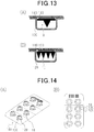
- transdermal administration device package With reference to Figs. 13 and 14 , an embodiment of a transdermal administration device package will be described as a third embodiment.
- Fig. 13 is a schematic cross sectional view which shows a cross section of an example of a transdermal administration device package in a direction perpendicular to the extending direction of the projection, that is, in the second direction.
- Fig. 14 is a schematic view which shows a perspective structure and a plan structure of an example of the transdermal administration device package.
- the transdermal administration device package includes the transdermal administration device 10 according to any one of the first embodiment, the second embodiment, and modifications thereof, a supportive casing 120, an adhesive holder 130, and a protective film 140.
- a supportive casing 120 As shown in Fig. 13 , the transdermal administration device package includes the transdermal administration device 10 according to any one of the first embodiment, the second embodiment, and modifications thereof, a supportive casing 120, an adhesive holder 130, and a protective film 140.
- a supportive casing 120 As shown in Fig. 13 , the transdermal administration device package includes the transdermal administration device 10 according to any one of the first embodiment, the second embodiment, and modifications thereof, a supportive casing 120, an adhesive holder 130, and a protective film 140.
- Detailed configuration of the support casing 120, the adhesive holder 130, and the protective film 140 will be described in the fourth embodiment.
- Fig. 13 shows an example of the transdermal administration device package including the transdermal administration device 10 which is not provided with the adhesive sheet 30. Further, Fig. 13(A) shows an example of the transdermal administration device 10 having one projection, and Fig. 13(B) shows an example of the transdermal administration device 10 having a plurality of projections.
- an adhesive holder 130 is disposed to support the substrate 21.
- the transdermal administration device 10 is temporarily fixed to the protective film 140 via the adhesive holder 130 attached on the protective film 140.
- the transdermal administration device 10 may be temporarily fixed to the support casing 120 instead of the protective film 140.
- Fig. 14 shows the transdermal administration device package in which eight transdermal administration devices 10 are fixed to the support casing 120.
- the eight transdermal administration devices 10 are arranged in two rows and four columns.
- Fig. 14(A) is a perspective view of the transdermal administration device package
- Fig. 14(B) is a plan view of the transdermal administration device package.
- the transdermal administration device package may include a plurality of transdermal administration devices 10 and the adhesive holder 130 provided for the respective transdermal administration devices 10.
- the transdermal administration device 10 is prevented from being impacted by other objects or being directly touched by the user's hand since the transdermal administration device 10 is packaged. As a result, deformation of the transdermal administration device 10 is prevented.
- FIG. 15 to 29 an embodiment of a production method of a transdermal administration device and a production method of a transdermal administration device package are described as a fourth embodiment.
- a method for producing the transdermal administration device 10 includes the steps of forming a molded product by filling a recess of an intaglio plate with a forming material of the administration section 20, and removing the molded product from the intaglio plate.
- the forming material of the administration section 20 may be provided to the intaglio plate singularly or in the form of liquid having the forming material dissolved or dispersed therein.
- the intaglio plate for use in production of the transdermal administration device includes a recess having a shape in conformity with the shape of the projection of the transdermal administration device 10.
- the recess is formed to have the longitudinal direction which is an extending direction of the recess when viewed in the direction perpendicular to the surface of the intaglio plate corresponds to a removal proceeding direction, which is a direction in which the molded product made of the forming material of the administration section 20 is removed from the intaglio plate.
- Fig. 15 shows that recesses 51 of an intaglio plate 50 which is a roll-shaped mold are filled with the forming material of the administration section 20, and a molded product after being formed is removed from the intaglio plate 50.
- the plan shape of the respective recesses 51 viewed in the direction perpendicular to the surface of the intaglio plate 50 extends in the removal proceeding direction, that is, the circumferential direction of the intaglio plate 50.
- the longitudinal direction of the recess 51 viewed in the direction perpendicular to the surface of the intaglio plate 50 corresponds to the removal proceeding direction.
- the above arrangement of the recesses 51 facilitates removal of the molded product from the intaglio plate 50. Accordingly, the precision of shape-transfer from the intaglio plate 50 to the forming material of the administration section 20 is improved.
- the intaglio plate may have a plate-shape as long as the recesses are arranged such that the plan shape of the recesses viewed in the direction perpendicular to the surface of the intaglio plate extends in the removal proceeding direction.
- a step of fabricating an original plate is a step of preparing a forming material of the original plate and fabricating an original plate by using a micromachining technique.
- the forming material of the original plate is not specifically limited, and is preferably selected considering processing suitability or availability of the material.
- the forming material of the original plate include metal materials such as stainless steel (SUS), aluminum and titanium, ceramics such as alumina, aluminum nitride, and machinable ceramics, hard brittle materials such as silicon and glass, and organic materials such as acryl and polyacetal.
- the fabrication method of the original plate is not specifically limited, and a known method may be used depending on the shape of the original plate to be fabricated.
- the original plate may be fabricated by using a micromachining technique or a machine processing technique used for production of semiconductor devices.
- micromachining technique used for fabrication of original plate includes, for example, lithography, wet etching, dry etching, sand blasting, laser processing, and micromachining.
- a surface shape processing or chemical surface modification may be applied on the original plate. Specifically, grinding, boring, or grooving by machine processing, surface treatment and surface modification by using an etching process, or application of a mold release agent may be advantageously used.
- the original plate thus obtained is used as a plate for fabrication of the intaglio plate.
- a forming material of the intaglio plate is supplied onto the surface of the original plate. After curing of the forming material of the intaglio plate, the original plate is separated from the forming material to fabricate the intaglio plate having a shape of the original plate reproduced as a recessed shape.
- the intaglio plate thus fabricated allows for production of a large number of transdermal administration devices 10 from the same intaglio plate. Accordingly, the production cost of the transdermal administration device 10 can be reduced, thereby improving the productivity.
- the forming material of the intaglio plate examples include inorganic materials such as nickel, silicon, silicon carbide, tantalum, glassy carbon, quartz, and silica, and resin compositions such as silicone resin, urethane rubber, norbornene resin, polycarbonate, polyethylene terephthalate, polystyrene, polymethacrylic acid methyl, acryl, and liquid crystal polymer.
- the forming material is preferably silicone resin, nickel, silicon, silicon carbide, tantalum, glassy carbon, quartz and silica, more preferably silicone resin, and particularly preferably silicone resin containing polydimethyl siloxane.
- silicone resin containing polydimethyl siloxane with a hardener added thereto can be used.
- Use of the silicone resin having high mold releasability improves the releasability of cured forming material of the intaglio plate, thereby preventing deformation of the intaglio plate when being removed from the mold.
- the production method of the intaglio plate is not limited to the above-mentioned methods, and the intaglio plate can be produced by a known shape-transfer technique.
- an intaglio plate made of nickel may be produced by nickel electroforming.
- the production method of the intaglio plate in the above description includes producing an original plate, and producing an intaglio plate from the original plate.
- the intaglio plate may also be produced by directly processing the forming material of the intaglio plate.
- the administration section 20 is produced as a molded product by molding the thermally melted forming material by using an intaglio plate.
- an intaglio plate For transfer forming from the intaglio plate to the forming material, a known technique may be used.
- the forming material of the administration section 20 is a material that dissolves in water contained in the skin, such as a water soluble polymer or disaccharide
- a liquid material having the forming material dissolved or dispersed in a solvent such as water is first prepared. Then, the liquid material is introduced into the recess of the intaglio plate, and is dried to remove the solvent in the liquid material to thereby form a molded product, which is the administration section 20.
- a known technique may be used for transfer forming from the intaglio plate to the forming material.
- the production method of the transdermal administration device is only required to include the steps of forming a molded product by filling the recess of the intaglio plate with the forming material of the administration section 20 and removing the molded product from the intaglio plate so that removal is carried out in the extending direction of the recess when viewed in the direction perpendicular to the surface of the intaglio plate, and the details of these steps may be different from the description below.
- a production method of the transdermal administration device which uses a thermoplastic resin as a forming material of the administration section 20 will be described.
- an intaglio plate 60 fabricated by the above production method is prepared.
- the intaglio plate 60 includes a recess 61 having a shape in conformity with the shape of the projection of the administration section 20 of the production target.
- the plurality of recesses 61 includes the recesses 61 arranged in the extending direction of the recess 61.
- the intaglio plate is not limited to the plate-shaped intaglio plate 60 shown in Fig. 16 , but may be a roll-shaped intaglio plate shown in Fig. 15 .
- a resin material 70 which is a thermoplastic resin is then disposed on the surface of the intaglio plate 60 as a forming material of the administration section 20.
- the resin material 70 may be supplied onto the intaglio plate 60 in a heated state.
- Fig. 18 shows an example of press operation by using a plate-shaped press material 80, press operation may be performed by using a roll-shaped press material.
- the arrow in Fig. 18 shows a press direction.
- the molded product 71 is then removed from the intaglio plate 60.
- the direction in which the molded product 71 made of the forming material of the administration section 20 is removed from the intaglio plate 60 corresponds to the extending direction of the recess 61 viewed in the direction perpendicular to the intaglio plate 60.
- the removed molded product 71 is the administration section 20.
- the administration section 20 is formed.
- the administration section 20 may be produced not only by thermal compression molding as described in Figs. 16 to 20 , but also by injection molding or the like.
- the obtained administration section 20 is provided as the transdermal administration device 10 by itself or together with other member bonded thereto such as the adhesive sheet 30.
- the administration section 20 and the adhesive sheet 30 can be bonded to each other by a conventional technique.
- the molded product 71 and the adhesive sheet 30 may be bonded after the molded product 71 is formed on the intaglio plate 60, and then removed from the intaglio plate 60 to obtain a structure made up of the administration section 20 and the adhesive sheet 30.
- the outer shape of the molded product 71 or the combination of the molded product 71 and the adhesive sheet 30 or the like may be adjusted as necessary by cutting the outer portion of the substrate 21 by punching or the like using a Thomson blade or the like.
- a production method of the transdermal administration device which uses a material that dissolves in water contained in the skin as a forming material of the administration section 20 will be described.
- an intaglio plate 62 fabricated by the above production method is prepared.
- the intaglio plate 62 includes a recess 63 having a shape in conformity with the shape of the projection of the administration section 20 of the production target, and a recess 64 having an outer shape in conformity with the outer shape of the substrate of the administration section 20 of the production target.
- the recess 63 communicates with the recess 64, and the recess 63 is located closer to the bottom of the intaglio plate 62 than the recess 64 is.
- the intaglio plate 62 includes a plurality of recesses 63
- the plurality of recesses 63 includes the recesses 63 arranged in the extending direction of the recess 63.
- the intaglio plate is not limited to the plate-shaped intaglio plate 62 shown in Fig. 21 , but may be a roll-shaped intaglio plate shown in Fig. 15 .
- a liquid material LQ having the forming material of the administration section 20 dissolved or dispersed in a solvent is prepared, and the liquid material LQ is filled into the recesses 63 and 64 of the intaglio plate 62.
- the flowability of the liquid material LQ is preferably adjusted to an extent such that the liquid material LQ is smoothly filled into the recesses 63 and 64 by adjusting the amount of the solvent or the like as appropriate.
- the liquid material LQ can be supplied to the intaglio plate 62 by methods such as spin coating, use of dispenser, casting, and ink jetting.
- Supplying of the liquid material LQ to the intaglio plate 62 may be performed under normal pressure, but preferably under reduced pressure or vacuum in order to smoothly supply the liquid material LQ into the recesses 63 and 64.
- the supply amount of the liquid material LQ to the intaglio plate 62 is an extent that the liquid material LQ covers at least the entire recess 63.
- the liquid material LQ may be pressurized toward the bottom of the intaglio plate 62 so as to facilitate filling of the liquid material LQ into the recesses 63 and 64.
- liquid materials which contain forming materials of different compositions may be sequentially filled into the recesses 63 and 64.
- the liquid material LQ filled in the recesses 63 and 64 of the intaglio plate 62 is dried to remove the solvent. As a result, the molded product 72 is formed.
- the molded product 72 is then removed from the intaglio plate 62.
- the direction in which the molded product 72 made of the forming material of the administration section 20 is removed from the intaglio plate 62 corresponds to the extending direction of the recess 63 viewed in the direction perpendicular to the intaglio plate 62.
- the removed molded product 72 is the administration section 20.
- the administration section 20 is formed.
- the obtained administration section 20 is provided as the transdermal administration device 10 by itself or together with other member bonded thereto such as the adhesive sheet 30.
- the administration section 20 and the adhesive sheet 30 can be bonded to each other by a conventional technique.
- the molded product 72 and the adhesive sheet 30 may be bonded after the molded product 72 is formed on the intaglio plate 62, and then removed from the intaglio plate 62 to obtain a structure made up of the administration section 20 and the adhesive sheet 30.
- the outer shape of the molded product 72 or the combination of the molded product 72 and the adhesive sheet 30 or the like may be adjusted as necessary by cutting the outer portion of the substrate 21 by punching or the like using a Thomson blade or the like.
- the molded product of the administration section 20 may also be formed by applying pressure onto a sheet made of the forming material of the substrate 21 which is placed on the forming material of the projection filled in the recess 63 of the intaglio plate 62.
- the conventional production methods of a microneedle which has been proposed include fabricating an original plate of a projection by cutting work, producing an intaglio plate having an inverted pattern of bumps and dents of the original plate, and manufacturing an administration section having a projection made of resin by transfer molding using the intaglio plate.
- these production methods may have a phenomenon, so-called torare in Japanese, that the resin is adhered to the intaglio plate during removal of the molded product from the intaglio plate. If this phenomenon occurs, the precision of shape-transfer from the intaglio plate to the removed molded product is reduced.
- the forming material may be partially adhered to the intaglio plate during removal of the molded product from the intaglio plate, which may decrease the precision of shape-transfer from the intaglio plate to the removed molded product.
- the projection which is the production target has a shape extending along the first surface 21S of the substrate 21, and thus the recess of the intaglio plate for producing the projection has a shape extending in one direction when viewed in the direction perpendicular to the surface of the intaglio plate.
- the molded product is removed from the intaglio plate in the extending direction of the recess when viewed in the direction perpendicular to the surface of the intaglio plate, the molded product is easily removed from the intaglio plate compared with the case where the molded product is removed from the intaglio plate in the direction different from the extending direction of the recess such as that extending perpendicular to the extending direction of the recess.
- the forming material is prevented from being partially adhered to the intaglio plate during removal of the molded product. Accordingly, the precision of shape-transfer from the intaglio plate to the removed molded product is improved.
- This production method of the transdermal administration device package includes the above steps of fabricating the transdermal administration device 10, and the steps of bonding a protective sheet having easy adhesiveness to a surface of the substrate of the transdermal administration device 10 opposite from the tip of the projection via a detachable adhesive material, bonding a casing sheet to the protective sheet so as to cover the tip of the projection on the transdermal administration device 10 and house the transdermal administration device 10, and cutting the protective sheet and the casing sheet bonded to each other.
- Fig. 26 is a flow chart which shows a production process of the transdermal administration device package when the administration section 20 of the transdermal administration device 10 is made of a thermoplastic resin.
- Step S1 shown in Fig. 26 is a step of providing a thermoplastic resin which is the forming material of the administration section 20 onto the intaglio plate.
- Step S2 shown in Fig. 26 is a step of forming a molded product by thermal compression molding by filling the recess of the intaglio plate with the resin and removing the molded product from the intaglio plate to obtain the administration section 20.
- the transdermal administration device 10 is fabricated by Steps S1 and S2. Subsequent to Step S2, the protective sheet is bonded to the transdermal administration device 10 via the adhesive material in Step S3. Subsequent to Step S4, the protective sheet and the casing sheet are punched out after the casing sheet and the protective sheet are bonded to each other.
- Fig. 27 is a schematic view which shows a production process of the transdermal administration device package.
- Fig. 28 is a schematic view which shows part of the process shown in Fig. 27 by which the transdermal administration device 10 fixed to the protective sheet is produced.
- Fig. 29 is a schematic view which shows part of the process shown in Fig. 27 by which the transdermal administration device 10 fixed to the protective sheet is packed with the casing sheet and the protective sheet and the casing sheet are punched out to produce the transdermal administration device package.
- a sheet made of resin which is the forming material of the administration section 20 is fed out.
- the resin sheet is heated and pressed against the intaglio plate to produce the projection.
- the protective sheet is bonded via the adhesive material to a surface of the resin sheet opposite from the surface on which the projection is formed.
- the resin sheet and the adhesive material are punched out to produce the administration section 20 and the adhesive holder 130 on the protective sheet.
- the part remaining after the resin sheet and the adhesive material are punched out that is, the part other than the administration section 20 and the adhesive holder 130 located between the administration section 20 and the protective sheet is separated from the protective sheet, taken up and recovered.
- the transdermal administration device 10 fixed to the protective sheet via the adhesive holder 130 is produced.
- a sheet made of resin which is the forming material of the support casing 120 is fed out.
- the resin sheet is molded into a shape of the array of the plurality of recesses of the support casing 120.
- a casing sheet is formed.
- the bonding process the casing sheet and the protective sheet are bonded to each other so that the transdermal administration device 10 fixed to the protective sheet is covered by the recess.
- the punching process the casing sheet and the protective sheet are punched out to produce the transdermal administration device package.
- the transdermal administration device package thus produced includes, as shown in Fig. 13 , the transdermal administration device 10, the support casing 120 formed by punching the casing sheet, the protective film 140 formed by punching the protective sheet, and the adhesive holder 130 disposed between the transdermal administration device 10 and the protective film 140.
- a space in the transdermal administration device package that houses the transdermal administration device 10 is sealed by the protective film 140 which covers an opening of the support casing 120.
- the adhesive holder 130 is made of a material having adhesiveness at least capable of holding the transdermal administration device 10, and may be designed as appropriate depending on the specification of the transdermal administration device 10.
- the adhesive holder 130 may be formed by a resin having viscoelasticity, an adhesive or the like.
- the adhesive holder 130 is preferably detachable to an adhesion target, and is preferably made of a gel polymer.
- the adhesive holder 130 made of a gel polymer has high adhesiveness, and can be repeatedly attached and removed from the adhesion target.
- the adhesive holder 130 made of a gel polymer can be repeatedly used since the adhesiveness can be restored by cleansing with distilled water, purified water, ethyl alcohol or the like.
- examples of gel polymer include silicone gel, urethane gel and the like.
- the support casing 120 can be formed by thermal pressing.
- a number of recesses, each having a size capable of housing the transdermal administration device 10 are formed by vacuum molding, vacuum pressure molding or the like so as to be arrayed in a matrix on a sheet material having an elongated strip shape.
- the sheet material is cut off into eight recesses arranged in two rows and four columns to form the support casing 120.
- the shape of the recess can be designed as appropriate depending on the shape of the transdermal administration device 10, and may be, for example, a circle, ellipse, oblong circle, or a rectangle in plan view. Further, the number of recesses included in one support casing 120 may be arbitrarily determined depending on the number of the transdermal administration devices 10 housed in the support casing 120.
- the sheet material used for formation of the support casing 120 may be a sheet material made of a known synthesized resin material such as polyvinyl chloride, polyethylene terephthalate, polypropylene, polyethylene, nylon, or ethylene-vinyl alcohol copolymer resin.
- the sheet material is preferably a transparent synthesized resin material since it has high gas barrier properties and transparency which allows for visual inspection of the transdermal administration device 10 from the outside of the support casing 120 to easily check a foreign substance in the recess.
- the forming material of the sheet material is preferably an ethylene-vinyl alcohol copolymer.
- the transdermal administration device 10 is fixed to the protective film 140 by positioning the adhesive holder 130 on one surface of the protective film 140 so that the adhesive holder 130 holds the transdermal administration device 10. Since the transdermal administration device 10 is prevented from being moved in the recess of the support casing 120 during transportation of the transdermal administration device package or the like, the transdermal administration device 10 can be advantageously stored or transported. In particular, when the plurality of transdermal administration devices 10 are housed in one support casing 120, collision between each of the transdermal administration devices 10 can be reduced.
- the support casing 120 can be sealed with the protective film 140 by using a heat sealer. That is, the protective sheet which is the protective film 140 is disposed to cover the opening of the support casing 120, and is thermally shrunk by applying heat to the protective sheet to thereby seal the recess in which the transdermal administration device 10 is housed. Sealing of the recess can prevent degeneration of the transdermal administration device 10 due to environmental change.
- the protective film 140 is preferably a resin film that has strong adhesiveness to the support casing 120 when being bonded to the support casing 120, and easy openness when being peeled from the support casing 120 to open the transdermal administration device package.
- the user peels the protective film 140 from the support casing 120 and takes out the transdermal administration device 10 which is detachably attached to the protective film 140. Then, the user pierces the projection of the transdermal administration device 10 into the skin. Since the transdermal administration device 10 is packaged, it is prevented from being impacted by other objects or being directly touched by the user's hand. As a result, deformation of the transdermal administration device 10 is prevented.
- the transdermal administration device 10 housed in the transdermal administration device package is preferably sterilized.
- the transdermal administration device 10 can be sterilized by dried heated air, hydrogen peroxide gas, ethylene oxide gas, electron beam radiation, or ⁇ beam radiation.
- use of low energy electron beam is widely adopted since the method can be conducted at low temperature and does not leave a residue in the sterilized object, and the handling is safe and easy.
- high temperature processing cannot be performed.
- sterilization must be performed not only on the outer surface of the projection but also on the inner area where the drug is filled. Accordingly, sterilization by ⁇ beam radiation is preferably performed.
- sterilization performed on the transdermal administration device 10 can maintain the inside of the support casing 120 of the transdermal administration device package to have an aseptic state over a long period of time.
- the fourth embodiment can be implemented with modifications as described below.
- the administration section 20 can be produced by various known techniques depending on the forming material of the administration section 20.
- the administration section 20 may also be produced without using the intaglio plate.
- the administration section 20 when the administration section 20 is made of resin, the administration section 20 can be produced by molding techniques such as injection molding, extrusion molding, imprinting, hot embossing, and casting.
- the administration section 20 can also be produced by micromachining techniques such as lithography, wet etching, dry etching, sand blasting, and laser processing.
- the original plate may be produced by these techniques.
- the original plate of the administration section was produced from an acrylic plate by micromachining.
- the projection had the same shape as that of the projection 22 of the first embodiment, and the auxiliary lateral face is a flat surface.
- the height H of the projection was approximately 500 ⁇ m
- the width D1 of the projection was approximately 770 ⁇ m
- the width D2 of the projection was approximately 280 ⁇ m
- the length L of the tip was approximately 500 ⁇ m
- the height Hs of the main lateral face was approximately 520 ⁇ m
- the height Hf of the auxiliary lateral face was approximately 520 ⁇ m
- the angle ⁇ 1 of the main apex angle was approximately 105 degrees
- the angle ⁇ 2 of the auxiliary apex angle was approximately 30 degrees.
- the 36 projections were arrayed on the substrate in a matrix of six rows and six columns with a pitch of 1 mm.
- thermosetting silicone resin was applied on the surface of the projection of the original plate formed of an acrylic plate, and was removed after being thermally cured to obtain the intaglio plate made of silicone.
- the recesses which correspond to the 36 projections were formed on the intaglio plate.
- the liquid material containing the forming material of the administration section which was 0.1% Evans Blue/5% chitosan succinamide aqueous solution, was filled into the intaglio plate.
- the intaglio plate was heated at 90°C for 10 minutes so as to dry and solidify the liquid material.
- the solidified molded product was punched into a circle shape, and removed from the intaglio plate to obtain the administration section.
- the original plate of the administration section was produced from an aluminum plate by micromachining.
- the projection had the same shape as that of the projection 25 of the second embodiment, and the auxiliary lateral face is a curved surface.
- the height H of the projection was approximately 500 ⁇ m
- the width D1 of the projection was approximately 1500 ⁇ m
- the width D2 of the projection was approximately 340 ⁇ m
- the length L of the tip was approximately 500 ⁇ m
- the height Hs of the main lateral face was approximately 530 ⁇ m
- the height Hf of the auxiliary lateral face was approximately 707 ⁇ m
- the angle ⁇ 3 of the main apex angle was approximately 135 degrees
- the angle ⁇ 4 of the auxiliary apex angle was approximately 27 degrees.
- the 36 projections were arrayed on the substrate in a matrix of six rows and six columns with a pitch of 1 mm.
- the intaglio plate was fabricated by the same procedure as that of Example 1, the liquid material was filled into the intaglio plate to fabricate the administration section, and the adhesive sheet was bonded to the administration section to obtain the transdermal administration device of Example 2.
- the liquid material containing the forming material of the administration section which was 2% dextran/10% glycine/10% trehalose aqueous solution, was filled into the intaglio plate obtained in Example 2 by an ink jet method.
- the liquid material of 100nl was filled into the respective recesses which correspond to the projections, and then, chitosan succinamide 5% aqueous solution was further filled into the recesses.
- the dextran was fluorescent-labeled dextran. Thereafter, the intaglio plate was heated at 90°C for 10 minutes so as to dry and solidify the liquid material.
- the solidified molded product was punched into a circle shape, and removed from the intaglio plate to obtain the administration section having the fluorescent substance concentrated at the tip end of the projection.
- the adhesive sheet was bonded to the obtained administration section by the same procedure as that of Example 1 to obtain the transdermal administration device of Example 3.
- the transdermal administration device of Examples 1 to 3 was observed by using a stereoscopic microscope. As a result of observation, it was found that the formation rate of the projections, that is, the rate of the projections of the same shape as those of the original plate were formed on the administration section to the total number of the projections on the original plate was 100% for each of Examples 1 to 3.
- the transdermal administration device of Examples 1 to 3 was applied to a mouse.
- Example 3 a skin slice sample of the mouse to which the transdermal administration device was applied was prepared, and was observed by using a fluorescence microscope.
- the transdermal administration device was applied to the mouse by pressing the projection against the skin along the extending direction of the projection.
- the original plate of the administration section was produced from an aluminum plate by micromachining.
- the projection had the same shape as that of the projection 25 of the second embodiment, and the auxiliary lateral face is a curved surface.
- the height H of the projection was approximately 470 ⁇ m
- the width D1 of the projection was approximately 770 ⁇ m
- the length L of the tip was approximately 500 ⁇ m
- the height Hs of the main lateral face was approximately 500 ⁇ m
- the angle ⁇ 3 of the main apex angle was approximately 105 degrees
- an angle ⁇ 4 of the auxiliary apex angle was approximately 60 degrees.
- the 36 projections were arrayed on the substrate in a matrix of six rows and six columns with a pitch of 1 mm.
- the intaglio plate was fabricated in the same procedure as that of Example 1.
- the liquid material containing the forming material of the administration section which was hydroxypropyl cellulose aqueous solution, was filled into the intaglio plate.
- the intaglio plate was then heated at 90°C for 10 minutes so as to dry and solidify the liquid material.
- the solidified molded product was removed from the intaglio plate.
- the direction in which the molded product is removed from the intaglio plate corresponded to the extending direction of the recess viewed in the direction perpendicular to the intaglio plate.
- transdermal administration device of Example 4 formed of the administration section was obtained.
- the transdermal administration device of Example 4 was observed by using a scanning electron microscope. The result was that the height H of the projection was 471 ⁇ m, the width D1 of the projection was 769 ⁇ m, and the angle ⁇ 4 of the auxiliary apex angle was 59 degrees.
- Figs. 30(A) and (B) show the scanning electron microscope images of the transdermal administration device of Example 4.
- the liquid material containing the forming material of the administration section which was 0.1% Evans Blue/5% chitosan succinamide aqueous solution, was filled into the recess having a shape in conformity with the shape of the projection of the intaglio plate obtained in Example 4. Then, the intaglio plate was heated at 90°C for 10 minutes so as to dry and solidify the liquid material. Then, the liquid material containing the forming material of the administration section, which was 30% hydroxypropyl cellulose aqueous solution, was filled on the liquid material filled and solidified in the intaglio plate. The intaglio plate was heated at 90°C for 20 minutes so as to dry and solidify the liquid material.
- the solidified molded product was removed from the intaglio plate.
- the direction in which the molded product is removed from the intaglio plate corresponded to the extending direction of the recess viewed in the direction perpendicular to the intaglio plate.
- the transdermal administration device of Example 5 formed of the administration section was obtained.
- an upper layer that is, the projection is made of chitosan succinamide and Evans Blue
- a lower layer that is, substrate is made of hydroxypropyl cellulose.
- the transdermal administration device of Example 5 was observed by using an optical microscope. It was confirmed that the projection was blue and the substrate was transparent. That is, it was confirmed that the transdermal administration device of Example 5 had a two-layered structure in which the projection was formed of chitosan succinamide and Evans Blue, and the substrate was formed of hydroxypropyl cellulose.
- Figs. 31(A) to (D) show the microscopic images of the transdermal administration device of Example 5.
- the original plate which included the projection having the width D1 of approximately 800 ⁇ m, the width D2 of approximately 400 ⁇ m, and the height H of approximately 700 ⁇ m was fabricated, and a roll-shaped intaglio plate was fabricated by inverting the bumps and dents of the original plate.
- the recess which extends in the circumferential direction of the intaglio plate was formed on the intaglio plate.
- the long side of the recess that is, the side having the length of 800 ⁇ m which corresponds to the above width D1 extends in the circumferential direction of the intaglio plate
- the short side of the recess that is, the side having the length of 400 ⁇ m which corresponds to the above width D2 extends in the width direction of the intaglio plate.
- Polyglycolic acid was used as the forming material of the administration section, and the bumps and dents of the intaglio plate were inverted by thermal compression molding to thereby fabricate the transdermal administration device.
- the plurality of projections were formed on the transdermal administration device, and 95% or more of the projections were formed without being bent.
- 10...transdermal administration device 20...administration section, 21...substrate, 21S...first surface, 21T...second surface, 22,25,26,27...projection, 23A,23D,23F,23H...main lateral face, 23B,23E,23G,23I...auxiliary lateral face, 23C,23J...base, 24a...long side, 24b...short side, 24c,24f,24h...top edge, 24d,24e,24g,24i,24j...lateral edge, 30...adhesive sheet, 31...base sheet, 32...adhesive layer, 50,60,62...intaglio plate, 51,61,63...recess, 120...support casing, 130...adhesive holder, 140...protective film
Description
- The present invention relates to transdermal administration devices and methods for producing transdermal administration devices.
- Intradermal sites which are located inside the skin have a high immune response in the body. Since intradermal drug administration is expected to reduce the drug dosage required to achieve an administration effect compared with hypodermic administration by which a drug is delivered to a site under the skin, technical development for intradermal drug administration has been conducted.
- For example, intradermal drug administration includes a Mantoux method by which a drug is delivered into an upper site in the skin by using an injection needle, and iontophoresis by which an ionized drug is intradermally infiltrated by applying a weak electric current to the skin. Other examples include jet injection by which a drug is intradermally delivered by means of hydraulic pressure, and a drug delivery method by which a drug is intradermally delivered via a hole created by a microneedle having a fine needle.
- In the Mantoux method, which uses an injection needle for drug administration, many patients feel fear of injection needles in addition to pain caused by piercing using an injection needle. Further, iontophoresis and jet injection, which do not involve pain or fear caused by injection needles, require a large device for drug administration.
- On the other hand, a needle-shaped projection of a microneedle is so small that patients would not feel pain or fear, and a method using a microneedle can perform drug administration without using a large device (for example, see PTLs 1 to 3).
-
- [PTL 1]
WO2008/013282 - [PTL 2]
WO2008/004597 - [PTL 3]
WO2008/020632 - Further,
US2004/087992 A1 discloses a closest prior art document with regard to the subject-matter of the independent claims.US202/115957 A1 shows another example of a prior art device andJP 2014113318 A - However, since a needle-shaped projection of a microneedle has an elongated shape extending from a surface of a plate-shaped substrate, it does not have a sufficient strength against a force in the lateral direction which is parallel to the surface of the substrate. When the projection pierces the skin, force in the lateral direction is inevitably applied to the projection since the surface of the skin is not flat. Accordingly, if lateral force is excessively applied to the projection, the projection is bent or collapsed, leading to decrease in piercing properties of the projection.
- Therefore, in transdermal administration devices such as microneedles having a fine projection to create a passage for intradermal drug administration, there is a need for a device having a projection which is not easily deformed compared with that of the microneedle.
- The present invention has an object of providing a transdermal administration device that reduces deformation of a projection and a method for producing the transdermal administration device.
- A transdermal administration device that solves the above problem includes an administration section including a substrate having a first surface and a second surface which is a surface opposite from the first surface, and a projection which protrudes from the first surface, wherein the projection has a shape extending along the first surface, and includes: one linear top edge which is located away from the first surface, the top edge having a first end and a second end; two main lateral faces which have the top edge in common with each other, the two main lateral faces having lateral edges, each lateral edge individually connecting the first end of the top edge and the first surface; and an auxiliary lateral face which has the lateral edges in common with the respective main lateral faces and forms one corner together with the two main lateral faces, an angle made between the lateral edge and the top edge on the main lateral face is an obtuse angle, and an angle made between the two lateral edges on the auxiliary lateral face is an acute angle.
- According to the above configuration, in piercing of the projection into the target, a corner of the projection formed by the two main lateral faces and the auxiliary lateral face is first pierced into the target. At this time, the corner is subject to an external force having a large component directed in the first direction, which is an extending direction of the projection. Since an angle formed between the top edge and the lateral edge on the main lateral face is an obtuse angle, the corner has high strength against the external force acting on the corner, compared with a case where the angle is a right angle or an acute angle. On the other hand, since the angle made between the two lateral edges on the auxiliary lateral face is an acute angle, the corner has a sharp shape when viewed in the first direction compared with a case where the angle is a right angle or an acute angle. As a result, since the sharpness of the corner viewed in the first direction is prevented from being excessively reduced and the strength of the corner against the external force in the first direction can be enhanced, deformation of the projection can be reduced.
- In the above transdermal administration device, the auxiliary lateral face may include a base side located within the first surface, and an aspect ratio which is a ratio of a height of the auxiliary lateral face to a length between both ends of the base side may be larger than 1.
- According to the above configuration, the aspect ratio of the auxiliary lateral face is larger than 1. Accordingly, the auxiliary lateral face has a sharp shape compared with a case where the aspect ratio of the auxiliary lateral face is not more than 1. As a result, the corner has higher sharpness, which facilitates piercing of the projection.
- In the above transdermal administration device, the auxiliary lateral face may be a triangular flat surface having an apex made by the first end of the top edge.
- According to the above configuration, the auxiliary lateral face is a triangular flat surface, and accordingly, designing of an angle made between the top edge and the lateral edge and designing of an angle of the corner viewed in the first direction are facilitated.
- In the above transdermal administration device, the auxiliary lateral face may be a curved surface which curves inward to the projection.
- According to the above configuration, the auxiliary lateral face which constitutes the corner is pierced into the target by digging into the target. Accordingly, the projection can be easily pierced into the skin compared with a case where the auxiliary lateral face is a flat surface.
- In the above transdermal administration device, the auxiliary lateral face may be a first auxiliary lateral face, the lateral edge may be a first lateral edge, the two main lateral faces may have lateral edges, each lateral edge individually connecting the second end of the top edge and the first surface, and the transdermal administration device may further includes a second auxiliary lateral face which has the second lateral edges in common with the respective main lateral faces and forms one corner together with the two main lateral faces.
- In the above transdermal administration device, a direction along which the projection extends may be a first direction, the top edge may extend along the first direction, the substrate may have a shape extending along the first direction when viewed in a direction perpendicular to the first surface, the transdermal administration device may include a plurality of the projections, and the plurality of projections may include the plurality of the projections disposed at different positions in the first direction on the first surface.
- According to the above configuration, the direction in which a user of the transdermal administration device can easily press the substrate against the target matches the direction in which the projection should be pressed against the target. Therefore, the projection can be easily pierced into the target.
- In the above transdermal administration device, a direction along which the projection extends may be the first direction, the top edge may extend along the first direction, the transdermal administration device may include the plurality of the projections, the plurality of projections may include the plurality of the projections disposed at different positions in the first direction on the first surface, the transdermal administration device may further include an adhesive sheet having an adhesive surface, the adhesive surface may be bonded to the second surface, and the adhesive surface may have a shape extending along the first direction when viewed in the direction perpendicular to the first surface and protrude outward from the substrate.
- According to the above configuration, the direction in which a user of the transdermal administration device can easily press the adhesive surface against the target matches the direction in which the projection of the administration section bonded to the adhesive surface should be pressed against the skin. Therefore, the projection can be easily pierced into the target.
- In the above transdermal administration device, the substrate may have a shape extending along the first direction when viewed in the direction perpendicular to the first surface.
- According to the above configuration, both the direction in which a user of the transdermal administration device can easily press the substrate against the target and the direction in which a user can easily press the adhesive surface against the target match the direction in which the projection should be pressed against the target. Therefore, the projection can be easily pierced into the target.
- A method of producing a transdermal administration device that solves the above problem includes the steps of: forming a molded product by filling a recess of an intaglio plate with a forming material of the administration section, the recess being formed to conform with a shape of the projection; and removing the molded product from the intaglio plate so that removal is carried out in an extending direction of the recess when viewed in a direction perpendicular to a surface of the intaglio plate.
- According to the above method, the above transdermal administration device can be produced. This transdermal administration device can reduce deformation of the projection as described above.
- Further, methods for producing a microneedle have been proposed in which an administration section is produced by transfer molding using an intaglio plate. For example, the intaglio plate is filled with thermoplastic resin to produce a molded product, and the molded product is removed from the intaglio plate to form an administration section. However, these production methods may have a phenomenon that the resin is adhered to the intaglio plate during removal of the molded product from the intaglio plate. If this phenomenon occurs, the precision of shape-transfer from the intaglio plate to the removed molded product is reduced. Moreover, even if a material other than a thermoplastic resin is used as a forming material of the administration section, the forming material may be partially adhered to the intaglio plate during removal of the molded product from the intaglio plate, which may decrease the precision of shape-transfer from the intaglio plate to the removed molded product.
- On the other hand, according to the above method for producing a transdermal administration device, the molded product is easily removed from the intaglio plate since the molded product is removed from the intaglio plate in the extending direction of the recess when viewed in the direction perpendicular to the surface of the intaglio plate. As a result, the forming material is prevented from being partially adhered to the intaglio plate. Accordingly, the precision of shape-transfer from the intaglio plate to the removed molded product is improved.
- According to the present invention, deformation of the projection can be reduced.
-
-
Fig. 1 is a perspective view which shows a perspective structure of a transdermal administration device of a first embodiment. -
Fig. 2 is a perspective view which shows a perspective structure of a projection of the first embodiment. -
Fig. 3 is a view which shows each structure of a main lateral face and an auxiliary lateral face of a projection of the first embodiment when viewed in a direction perpendicular to each surface. -
Fig. 4 is a plan view which shows a plan structure of a transdermal administration device of the first embodiment. -
Fig. 5 is a view which schematically shows a position of the projection along with a skin surface immediately before the transdermal administration device of the first embodiment is pierced into the skin of an administration target. -
Fig. 6 is a view which schematically shows a position of the projection along with a skin surface when the transdermal administration device of the first embodiment is being pierced into the skin of an administration target. -
Fig. 7 is a view which schematically shows a relationship between an array of a plurality of projections and change in position where a pressing force is applied while the transdermal administration device of the first embodiment is pressed against the skin. -
Fig. 8 is a perspective view which shows a perspective structure of a projection of a second embodiment. -
Fig. 9 is a view which shows each structure of a main lateral face and an auxiliary lateral face of a projection of the second embodiment when viewed in a direction perpendicular to each surface. -
Fig. 10 is a perspective view which shows a perspective structure of a projection of a modified example. -
Fig. 11 is a view which shows each structure of a main lateral face and an auxiliary lateral face of a projection of the modified example when viewed in a direction perpendicular to each surface. -
Fig. 12 is a perspective view which shows a perspective structure of a projection of a modified example. -
Fig. 13 is a cross sectional view which shows a cross sectional structure of a transdermal administration device package of a third embodiment, and includes (A) which shows a cross sectional structure of a transdermal administration device package which includes a transdermal administration device having one projection, and (B) which shows a cross sectional structure of a transdermal administration device package which includes a transdermal administration device having a plurality of projections. -
Fig. 14 includes (A) which is a perspective view that shows a perspective structure of the transdermal administration device package of the third embodiment, and (B) which is a plan view that shows a plan structure of the transdermal administration device package of the third embodiment. -
Fig. 15 is a schematic view which shows an intaglio plate used in a method for producing a transdermal administration device of a fourth embodiment and a molded product removed from the intaglio plate. -
Fig. 16 is a view which shows part of a production process of the transdermal administration device of the fourth embodiment, and shows the intaglio plate. -
Fig. 17 is a view which shows part of the production process of the transdermal administration device of the fourth embodiment, and shows that the forming material of the administration section is provided into the intaglio plate. -
Fig. 18 is a view which shows part of the production process of the transdermal administration device of the fourth embodiment, and shows that the forming material of the administration section is filled into the intaglio plate to produce the molded product. -
Fig. 19 is a view which shows part of the production process of the transdermal administration device of the fourth embodiment, and shows that the molded product is removed from the intaglio plate. -
Fig. 20 is a view which shows part of the production process of the transdermal administration device of the fourth embodiment, and shows the administration section which is the removed molded product. -
Fig. 21 is a view which shows part of the production process of the transdermal administration device of the fourth embodiment, and shows the intaglio plate. -
Fig. 22 is a view which shows part of the production process of the transdermal administration device of the fourth embodiment, and shows that the forming material of the administration section is supplied into the intaglio plate. -
Fig. 23 is a view which shows part of the production process of the transdermal administration device of the fourth embodiment, and shows that the forming material of the administration section is filled into the intaglio plate to produce the molded product. -
Fig. 24 is a view which shows part of the production process of the transdermal administration device of the fourth embodiment, and shows that the molded product is removed from the intaglio plate. -
Fig. 25 is a view which shows part of the production process of the transdermal administration device of the fourth embodiment, and shows the administration section which is the removed molded product. -
Fig. 26 is a view which shows a flow of a production process of a transdermal administration device package of the fourth embodiment. -
Fig. 27 is a view which schematically shows the production process of the transdermal administration device package of the fourth embodiment. -
Fig. 28 is a view which schematically shows a process in which the transdermal administration device fixed to a protective sheet is formed in the production process of the transdermal administration device package of the fourth embodiment. -
Fig. 29 is a view which schematically shows a process in which the transdermal administration device fixed to the protective sheet is covered with a casing sheet and the protective sheet and the casing sheet are punched to form the transdermal administration device package in the production process of the transdermal administration device package of the fourth embodiment. -
Fig. 30 includes (A) and (B) which are scanning electron microscope images of the transdermal administration device of Example 4. -
Fig. 31 includes (A) to (D) which are microscopic images of the transdermal administration device of Example 5. - With reference to
Figs. 1 to 7 , an embodiment of a transdermal administration device is described as a first embodiment. - With reference to
Fig. 1 , an overall configuration of a transdermal administration device will be described. - As shown in
Fig. 1 , atransdermal administration device 10 includes anadministration section 20 and anadhesive sheet 30. - The
administration section 20 includes a plate-shapedsubstrate 21 and a plurality ofprojections 22 which protrude from thesubstrate 21. Thesubstrate 21 has afirst surface 21S on which theprojections 22 are formed and asecond surface 21T which is a surface opposite from thefirst surface 21S. Thefirst surface 21S supports base ends of theprojections 22. - The
adhesive sheet 30 includes abase sheet 31 and anadhesive layer 32 which covers one of two surfaces of thebase sheet 31. Thesecond surface 21T of thesubstrate 21 is bonded to a portion of the adhesive surface of theadhesive layer 32. - With reference to
Figs. 2 and 3 , a detailed structure of a projection will be described. - As shown in
Fig. 2 , aprojection 22 is a filled solid made up of two main lateral faces 23A which are trapezoidal flat surfaces, two auxiliary lateral faces 23B which are triangular flat surfaces, and onebase 23C which is a rectangular flat surface. - The
base 23C is a defined surface located inside thefirst surface 21S of thesubstrate 21. Thebase 23C is defined by four sides, of which twolong sides 24a extend in a first direction and twoshort sides 24b, which are shorter than thelong side 24a, extend in a second direction. The first direction and the second direction are directions parallel to thefirst surface 21S, and the first direction and the second direction are perpendicular to each other. Further, a direction perpendicular to thefirst surface 21S, that is, a direction perpendicular to the first direction and the second direction is a third direction. - The two main lateral faces 23A have identical isosceles trapezoid shapes, and one of the two main lateral faces 23A intersects the
base 23C at along side 24a, and the other of the two main lateral faces 23A intersects thebase 23C at the otherlong side 24a. The main lateral faces 23A are each inclined relative to the third direction such that the two main lateral faces 23A intersect each other at theirtop edges 24c, which are opposite sides parallel to the correspondinglong sides 24a of the main lateral faces 23A. That is, the two main lateral faces 23A have the commontop edge 24c and separatelateral edges 24d. Thetop edge 24c has two ends, one of which is referred to as a first end, and the other is referred to as a second end. Twolateral edges 24d extend from the first end of thetop edge 24c, which are referred to as first lateral edges, and another twolateral edges 24d extend from the second end of thetop edge 24c, which are referred to as second lateral edges. - The two auxiliary lateral faces 23B have the identical isosceles triangular shapes. One of the auxiliary lateral faces 23B, which is a first auxiliary lateral face, intersects the
base 23C at itsshort side 24b, and the other of the auxiliary lateral faces 23B, which is a second auxiliary lateral face, intersects thebase 23C at itsshort side 24b. The auxiliary lateral faces 23B are each inclined relative to the third direction. Each auxiliarylateral face 23B intersects one of the two main lateral faces 23A at one of the twolateral edges 24d, which are equal sides of the isosceles triangle, and intersects the other of the two main lateral faces 23A at the other of the twolateral edges 24d. That is, the auxiliarylateral face 23B and each of the two main lateral faces 23A have thecommon lateral edges 24d. In other words, the first auxiliary lateral face and each of the two main lateral faces 23A have the common first lateral edge, and the second auxiliary lateral face and each of the two main lateral faces 23A have the common second lateral edge. Further, two main lateral faces 23A and one auxiliarylateral face 23B interposed between the two main lateral faces 23A form a corner. That is, theprojection 22 has a corner formed by the two main lateral faces 23A and the first auxiliary lateral face, and another corner formed by the two main lateral faces 23A and the second auxiliary lateral face. - In the
projection 22, thetop edge 24c is a tip. That is, the tip of theprojection 22 is formed in a linear shape extending along the first direction. - Thus, the
projection 22 has a blade shape extending along the first direction. - The
projection 22 has a height H which extends from thefirst surface 21S of thesubstrate 21 to the tip of theprojection 22 in the third direction. The height H is preferably in the range of 10 µm or more and 1000 µm or less, and is determined within this range depending on the depth required for a hole to be created by theprojection 22 into the administration target, that is, a passage through which a drug is administered into the skin. - When the administration target is the human skin and the depth of the hole is designed to be in the stratum corneum, the length H is preferably in the range of 10 µm or more and 300 µm or less, more preferably in the range of 30 µm or more and 200 µm or less. When the depth of the hole is designed to penetrate through the stratum corneum and not to reach the nerve, the height H is preferably in the range of 200 µm or more and 700 µm or less, more preferably in the range of 200 µm or more and 500 µm or less, and further more preferably in the range of 200 µm or more and 300 µm or less. When the depth of the hole is designed to reach the dermis, the height H is preferably in the range of 200 µm or more and 500 µm or less. When the depth of the hole is designed to reach the epidermis, the height H is preferably in the range of 200 µm or more and 300 µm or less.
- The
projection 22 has a width D1 in the first direction, which is a maximum length of theprojection 22 in the first direction. Further, theprojection 22 has a width D2 in the second direction, which is a maximum length of theprojection 22 in the second direction. That is, the width D1 is a length of thelong side 24a and the width D2 is a length of theshort side 24b, and the width D1 is larger than the width D2. Specifically, the width D1 is preferably in the range of 200 µm or more and 2000 µm or less, and the width D2 is preferably in the range of 1 µm or more and 1000 µm or less. - The
projection 22 has a length L of the tip, which is a length of a linear portion of theprojection 22 farthest from thefirst surface 21S of thesubstrate 21, that is, a length of thetop edge 24c. The length L of the tip is smaller than the width D1 and larger than the width D2. Specifically, the length L of the tip is preferably in the range of 100 µm or more and 1000 µm or less. - With reference to
Fig. 3 , the shape of the mainlateral face 23A and the auxiliarylateral face 23B will be described in detail. - As shown in
Fig. 3 , the mainlateral face 23A has an angle θ1 of a main apex angle made by thetop edge 24c, which constitutes the tip of theprojection 22, and thelateral edge 24d, which is a side connecting the end of thetop edge 24c and thefirst surface 21S of thesubstrate 21. The angle θ1 is an obtuse angle which is larger than 90 degrees and smaller than 180 degrees. Specifically, the angle θ1 of the main apex angle is preferably in the range of 110 degrees or more and 150 degrees or less. - The main
lateral face 23A has a height Hs which is a height of the isosceles trapezoid, that is, a minimum length from thelong side 24a to thetop edge 24c. An aspect ratio As of the mainlateral face 23A is a ratio of the height Hs to the length of thelong side 24a, that is, the width D1 of the projection 22 (As = Hs/D1). The aspect ratio As is preferably smaller than 1, more preferably in the range of 0.05 or more and 0.8 or less. - The auxiliary
lateral face 23B has an angle θ2 of an auxiliary apex angle, which is an apex of the isosceles triangle, that is, an angle formed between the twolateral edges 24d. The angle θ2 is an acute angle which is smaller than 90 degrees. Specifically, the angle θ2 of the auxiliary apex angle is preferably in the range of 10 degrees or more and 60 degrees or less. - The auxiliary
lateral face 23B has a height Hf which is a height of the isosceles triangle, that is, a minimum length from theshort side 24b to the apex of the auxiliarylateral face 23B. An aspect ratio Af of the auxiliarylateral face 23B is a ratio of the height Hf to the length of theshort side 24b which is a base side of the isosceles triangle, that is, the width D2 of the projection 22 (As = Hf/D2). The aspect ratio Af is preferably larger than 1, more preferably in the range of 1.2 or more and 4.6 or less. - Further, when the
projection 22 having the above configuration is viewed in a direction along the second direction, an angle between the side that constitutes the tip of theprojection 22 and the side that connects the tip of theprojection 22 and thefirst surface 21S of thesubstrate 21 of theprojection 22 is an obtuse angle larger than the angle θ1. In addition, when theprojection 22 is viewed in a direction along the first direction, an angle between two sides that connect the tip of theprojection 22 and thefirst surface 21S of thesubstrate 21 is preferably an acute angle larger than the angle θ2. - With reference to
Fig. 4 , a detailed configuration of the transdermal administration device will be described, focusing on the array of projections. - As shown in
Fig. 4 , when viewed in the direction perpendicular to thefirst surface 21S of thesubstrate 21, thesubstrate 21 has an outer shape having a longer dimension in the first direction than in the second direction. For example, thesubstrate 21 has a rectangular shape or an ellipse shape which is longer in the first direction than in the second direction. - When viewed in the direction perpendicular to the
first surface 21S of thesubstrate 21, theadhesive sheet 30 has an outer shape larger than thesubstrate 21 and having a longer dimension in the first direction than in thesecond direction substrate 21. For example, theadhesive sheet 30 has a rectangular shape or an ellipse shape which is similar to the shape of thesubstrate 21. When viewed in the direction perpendicular to thefirst surface 21S of thesubstrate 21, theadhesive sheet 30 extends outward from thesubstrate 21 such that the adhesive surface of theadhesive layer 32 is exposed. - In the above configuration, when viewed in the direction perpendicular to the
first surface 21S of thesubstrate 21, an extending direction of theprojection 22, an extending direction of thesubstrate 21, and an extending direction of theadhesive sheet 30 are aligned. In other words, when viewed in the direction perpendicular to thefirst surface 21S of thesubstrate 21, an extending direction of the tip of theprojection 22, a longitudinal direction of thesubstrate 21 along which the long side or longer diameter of thesubstrate 21 extends, and a longitudinal direction of theadhesive sheet 30 along which the long side or longer diameter of theadhesive sheet 30 extends are aligned. - The number of
projections 22 is not specifically limited, but is one or more. When theadministration section 20 includes a plurality ofprojections 22, the plurality ofprojections 22 are arranged with the extending direction of the tips of theprojections 22 being aligned as shown inFig. 4 . The plurality ofprojections 22 may be regularly or irregularly arranged on thefirst surface 21S of thesubstrate 21 as long as the extending direction of the tips of therespective projections 22 are aligned with each other and the plurality ofprojections 22 includes theprojections 22 that are disposed at different positions in the extending direction of thesubstrate 21. In other words, theprojections 22 are only required to be positioned such that the extending direction of the tip of theprojection 22, the longitudinal direction of thesubstrate 21, and the longitudinal direction of theadhesive sheet 30 are aligned, and, theprojections 22 are located at different positions in the longitudinal direction. For example, in the example shown inFig. 4 , the plurality ofprojections 22 are arranged in a grid pattern in the first direction and the second direction. - Forming materials of the
transdermal administration device 10 in the first embodiment will be described. - The
administration section 20 can be made of silicon, metal, ceramic, resin, or a material that dissolves in water contained in the skin. The forming material of theadministration section 20 is preferably a biocompatible material. A metal material used as a forming material of theadministration section 20 may be stainless steel, titanium, manganese or the like, and a ceramic material used as a forming material of theadministration section 20 may be glass, alumina or the like. However, the forming material of theadministration section 20 is not limited to these materials. A resin used for forming theadministration section 20 may be a medical grade silicone resin, polylactic acid, polyglycolic acid, polycarbonate, polyethylene, polypropylene, epoxy resin, polyamide resin, phenolic resin, polystyrene resin, polycaprolactone, acrylic resin, urethane resin, aromatic polyether ketone, cyclic olefin copolymer or the like. However, the forming material of theadministration section 20 is not limited to these materials. - In the configuration in which the
administration section 20 is made of a material that dissolves in water contained in the skin, theprojection 22 dissolves in the skin after it is pierced into the skin. Examples of a material that dissolves in water contained in the skin, that is, a water soluble material, include a water soluble polymer and disaccharide. - Examples of water soluble polymer include carboxymethyl cellulose (CMC), methylcellulose (MC), hydroxylpropyl cellulose (HPC), hydroxypropyl methylcellulose (HPMC), polyvinyl alcohol (PVA), polyacrylic acid polymer, polyacrylic amide (PAM), polyethylene oxide (PEO), pullulan, alginate, pectin, chitosan, chitosan succinamide, and oligochitosan. Among these materials, chitosan, oligochitosan, chitosan succinamide, carboxymethyl cellulose (CMC), hydroxypropyl cellulose (HPC), and hydroxypropyl methylcellulose (HPMC) are particularly desirable as a material for the
projection 22 since they have high biological safety. However, the forming material of theadministration section 20 is not limited to these materials. - The disaccharide is preferably trehalose or maltose. In particular, when the
projection 22 includes protein as a drug, trehalose serves to protect and stabilize the protein since trehalose, among others, has a crystal structure close to that of water. However, the forming material of theadministration section 20 is not limited to these materials. - Further, the
projection 22 may also include an additive such as stabilizer in addition to a water soluble polymer and disaccharide. - A drug administered by the
administration section 20 may be any kind of drug as long as it works when administered into the skin. A drug may be applied on the surface of theprojection 22 and delivered into the skin as theprojection 22 creates a hole in the skin. Alternatively, when theprojection 22 is made of a soluble material as described above, a drug may be contained inside theprojection 22 and delivered into the skin as theprojection 22 dissolves. Further, a liquid drug may be applied on the skin before or after theprojection 22 is pierced into the skin so that the drug is delivered into the skin through a hole created by theprojection 22. Moreover, a drug may be applied by combinations of these techniques. When theprojection 22 is made of a soluble material, a water soluble polymer that constitutes theprojection 22 may serve as a drug. - A drug may be, for example, various types of proteins, pharmacologically active agents, or cosmetic compositions, and is appropriately selected depending on the purpose.
- Examples of a pharmacologically active agent include vaccines such as influenza vaccine, pain relievers for cancer patients, insulin, biologics, gene therapy agents, injections, oral agents, skin application preparations and the like. In transdermal administration using the
administration section 20, a drug is administered into a hole created in the skin. Therefore, transdermal administration using theadministration section 20 can be applied to not only administration of the pharmacologically active agents used in the conventional transdermal administration, but also administration of pharmacologically active agents that requires hypodermic injection. In particular, since transdermal administration using theadministration section 20 does not cause pain by administration, it is suitable for administration of an injection drug such as vaccines for children. Further, since transdermal administration using theadministration section 20 does not require oral administration of a drug, it is suitable for administration of an oral drug for children who have difficulty in taking an oral drug. - Cosmetic compositions are compositions for use as cosmetics or beauty products. Examples of a cosmetic composition include humectants, colorants, fragrance, and physiologically active agents exhibiting cosmetic effects such as improvement effect on wrinkles, acne, stretch marks or the like, and improvement effect on hair loss or the like. When an aromatic material is used as a cosmetic composition, a fragrance can be imparted to the
administration section 20. Accordingly, thetransdermal administration device 10 suitable for use as a beauty product can be obtained. - In addition, the
substrate 21 and theprojection 22 may be made of a material having the same composition, or materials having different compositions. In the configuration in which thesubstrate 21 and theprojection 22 are made of a material having the same composition, thesubstrate 21 and theprojection 22 can be easily integrally formed. Moreover, when thesubstrate 21 is made of a soluble material, a drug may also be contained in thesubstrate 21. As thesubstrate 21 dissolves in a surface layer of the skin, the drug contained in thesubstrate 21 is introduced into the surface layer of the skin. - Although materials for the
adhesive sheet 30 are not specifically limited, thebase sheet 31 is formed of, for example, a resin film made of polyethylene terephthalate or the like, and theadhesive layer 32 is formed of, for example, an epoxy or acrylic adhesive. An adhesive is preferably made of a material having properties suitable for a skin patch, and more preferably, a material that withstands a sterilization process. - With reference to
Figs. 5 to 7 , effects of thetransdermal administration device 10 will be described while describing the steps of drug administration to the skin by thetransdermal administration device 10. - In use of the
transdermal administration device 10, theprojection 22 is oriented to the skin of administration target, thesubstrate 21 is pressed against the skin, and theadhesive sheet 30 exposed outside thesubstrate 21 is affixed to the skin. - Here, it is difficult to place the
substrate 21 parallel to the skin surface and press the entire surface of thefirst surface 21S against the skin at a time, since thesubstrate 21 and theadhesive sheet 30 have a certain amount of surface area and the surface of the skin of administration target is not a completely flat surface. Usually, edges of theadhesive sheet 30 and thesubstrate 21 are first pressed against the skin. - As a result, as shown in
Fig. 5 , theprojection 22 is pierced into the skin while thesubstrate 21 is in an inclined position to a skin surface S. Accordingly, a corner G formed by two main lateral faces 23A and the auxiliarylateral face 23B between the two main lateral faces 23A of theprojection 22 is first pierced into the skin. At this time, due to resistance from the skin, the corner G is subject to a force which presses the corner G in a direction away from the skin surface S. In particular, the auxiliarylateral face 23B of the corner G is subject to a reactive force F which presses the corner G in the first direction. - In the first embodiment, since the main apex angle of the main
lateral face 23A is an obtuse angle, the corner G has a high strength compared with a case where the main apex angle is a right angle or an acute angle. As a result, the corner G is prevented from being bent or collapsed. - On the other hand, since the auxiliary apex angle of the auxiliary
lateral face 23B is an acute angle, the corner G has sharpness compared with a case where the auxiliary apex angle is a right angle or an acute angle. Accordingly, even if the main apex angle is an obtuse angle, the sharpness of the corner G as a whole is prevented from being excessively reduced. - Further, as shown in
Fig. 6 , once the corner G is pierced into the skin, the tip of theprojection 22 adjacent to the corner G is gradually inserted into the skin. Theprojection 22 is then advanced into the skin to be entirely inserted into the skin. Here, since the main apex angle of the mainlateral face 23A is an obtuse angle, a hole which is first incised by the corner G is large compared with a case where the main apex angle is a right angle or an acute angle. Accordingly, the tip of theprojection 22 is easily inserted into the skin by using a hole incised by the corner G as a starting point. As a result, theentire projection 22 can be easily inserted into the skin. - Further, as shown in
Fig. 7 , it is easier for a user of thetransdermal administration device 10 to press thesubstrate 21 against the skin via theadhesive sheet 30 along the longitudinal direction of theadhesive sheet 30 and thesubstrate 21 than to press thesubstrate 21 against the skin along other directions. - On the other hand, in piercing of the
projection 22 into the skin, theprojection 22 needs to be pressed against the skin along the direction in which the tip extends. - In the first embodiment, the extending direction of the tip of the
projection 22, the longitudinal direction of thesubstrate 21, and the longitudinal direction of theadhesive sheet 30 are aligned. Accordingly, the direction in which a user of thetransdermal administration device 10 can easily press thesubstrate 21 against the skin matches the direction in which theprojection 22 should be pressed against the skin. Therefore, theprojection 22 can be easily pierced into the skin. - For example, in
Fig. 7 , thesubstrate 21 is pressed from the edge against the skin with a user's finger pressing theadhesive sheet 30 from the edge along the longitudinal direction of theadhesive sheet 30, that is, the first direction. As a result, theprojection 22 is pressed against the skin along the extending direction of the tip, and is pierced into the skin from the corner G as previously shown inFigs. 5 and 6 . - In addition, compared with a needle-shaped projection of the conventional microneedles, the
projection 22 of the first embodiment can ensure a large volume and a large surface area, and thus a large amount of drug capable of being contained in theprojection 22 and a large amount of drug capable of being applied on the surface of theprojection 22. Further, compared with the above projection of the conventional microneedles, theprojection 22 of the first embodiment can ensure a large area of the base which is defined within thefirst surface 21S of thesubstrate 21. As a result, in a production process of the administration section in which an intaglio plate is filled with a material for the administration section, which will be described later, a recess that corresponds to an administration section can be easily filled with the material. - From these points of view, the
projection 22 is preferably made of a water soluble material or made of both a water soluble material and a drug from among the above materials. In this configuration, deformation of theprojection 22 can be prevented, and furthermore, at least one of the amount of a substance delivered into the skin by theprojection 22, that is, the amount of a water soluble material and the amount of a drug can be increased. The conventional projection often has a cone or pyramid shape as described above, which is a conical shape elongated in a direction perpendicular to thefirst surface 21S of thesubstrate 21. Since a projection of a conical shape does not have sufficient volume, the amount of substance delivered into the skin by the conical shape projection may be insufficient. In contrast, theprojection 22 of thetransdermal administration device 10 according to the present embodiment has a large volume for the projection, compared with that of the conical shape projection. Accordingly, the amount of substance delivered into the skin can be increased by the projection. - Although the
projection 22 is preferably made of a water soluble material or made of both a water soluble material and a drug, theprojection 22 may also include an additive such as stabilizer in addition to these materials. - As described above, the
transdermal administration device 10 of the first embodiment can reduce occurrence of pain or fear in a patient by using fine projections similar to the conventional microneedle, and can perform drug administration without using a large device. Furthermore, theprojection 22 can be prevented from being deformed. The inventors of the present application have focused on the function of theprojection 22 to form a passage for drug administration by piercing the skin, in particular, focused on at what orientation theprojection 22 is inserted and advanced into the skin, and arrived at the idea of the shape of theprojection 22 in the present embodiment. - As described above, according to the transdermal administration device of the first embodiment, the following effects can be obtained.
- (1) Since the angle θ1 of the main apex angle of the main
lateral face 23A is an obtuse angle and the angle θ2 of the auxiliary apex angle of the auxiliarylateral face 23B is an acute angle, the sharpness of the corner G formed by the main lateral faces 23A and the auxiliarylateral face 23B viewed in the first direction is prevented from being excessively reduced and the strength of the corner G against an external force in the first direction can be enhanced. Therefore, deformation of theprojection 22 can be reduced. - (2) Since the aspect ratio Af of the auxiliary
lateral face 23B is larger than 1, the auxiliarylateral face 23B has a sharper shape than the auxiliarylateral face 23B with the aspect ratio Af of not more than 1. As a result, the corner G has higher sharpness, which facilitates piercing of theprojection 22. - (3) Since the auxiliary
lateral face 23B is a triangular flat surface having an apex made by an end of thetop edge 24c, designing of an angle of the main apex angle or the auxiliary apex angle is facilitated, and further, production of theprojection 22 is also facilitated. - (4) Since the extending direction of the tip of the
projection 22, the extending direction of thesubstrate 21, and the extending direction of theadhesive sheet 30 are aligned, the direction in which a user of thetransdermal administration device 10 can easily press thesubstrate 21 against the skin matches the direction in which theprojection 22 should be pressed against the skin. Therefore, theprojection 22 can be easily pierced into the skin. - With reference to
Figs. 8 and 9 , another embodiment of a transdermal administration device is described as a second embodiment. The second embodiment differs from the first embodiment in that the auxiliary lateral face of the projection is a curved surface. The second embodiment will be described focusing on differences from the first embodiment. Configurations the same as those of the first embodiment will be referred to by the same reference numbers, and the description thereof will be omitted. - As shown in
Fig. 8 , a projection 25 of the second embodiment is a filled solid made up of two main lateral faces 23D which are flat surfaces, two auxiliary lateral faces 23E which are curved surfaces, and onebase 23C. - The two main lateral faces 23D have the identical shape, and each main
lateral face 23D is surrounded by thelong side 24a and thetop edge 24c which are parallel to each other, and two curvedlateral edges 24e which connect thelong side 24a and thetop edge 24c. The main lateral faces 23D are each inclined relative to the third direction such that the two main lateral faces 23D intersect each other at theirtop edges 24c. Thetop edge 24c constitutes the tip of the projection 25, and tip of the projection 25 is formed in a linear shape extending along the first direction. Further, each mainlateral face 23D has an axisymmetric shape to a perpendicular bisector of thelong side 24a. - The two auxiliary lateral faces 23E have the identical shape, and each auxiliary
lateral face 23E is a curved surface surrounded by theshort side 24b and twolateral edges 24e and having a curvature which curves inward to the projection 25. The auxiliary lateral faces 23E are each inclined relative to the third direction. Each auxiliarylateral face 23E intersects one of the two main lateral faces 23D at one of the twolateral edges 24e and intersects the other of the two main lateral faces 23D at the other of the twolateral edges 24e. - That is, the
lateral edge 24d of theprojection 22 in the first embodiment has a linear shape, while thelateral edge 24e of the projection 25 in the second embodiment has a curved shape. Here, one plane formed by connecting three apexes on the auxiliarylateral face 23E, that is, one plane having an apex P1 which is an intersection between twolateral edges 24e and theshort side 24b is defined as a virtual plane N. A direction perpendicular to the virtual plane N is a normal direction M, which is indicated by the arrow inFig. 8 . - The height H, the width D1 in the first direction, the width D2 in the second direction, and the length L of the tip of the projection 25 are preferably in the range described previously for the height H, the width D1 in the first direction, the width D2 in the second direction, and the length L of the tip of the
projection 22 of the first embodiment. - With reference to
Fig. 9 , the shape of the mainlateral face 23D and the auxiliarylateral face 23E will be described in detail. InFig. 9 , the auxiliarylateral face 23E is shown projected onto the virtual plane N. - As shown in
Fig. 9 , the mainlateral face 23D has an angle θ3 of a main apex angle made by thetop edge 24c, which constitutes the tip of the projection 25, and thelateral edge 24e, which is a side connecting the end of thetop edge 24c and thefirst surface 21S of thesubstrate 21. The angle θ3 is an obtuse angle which is larger than 90 degrees and smaller than 180 degrees. Specifically, the angle θ3 of the main apex angle is preferably in the range more than 90 degrees and 135 degrees or less. - The main apex angle is an angle formed between a tangent Ta and the
top edge 24c. The tangent Ta is a line extends from the apex P2, which is an intersection between thetop edge 24c of the mainlateral face 23D and thelateral edge 24e, to be tangent to thelateral edge 24e. - The main
lateral face 23D has the height Hs which is a minimum length from thelong side 24a to thetop edge 24c. An aspect ratio As of the mainlateral face 23D is a ratio of the height Hs to the width D1 of the projection 22 (As = Hs/D1). The aspect ratio As is preferably smaller than 1, more preferably in the range of 0.05 or more and 0.8 or less. - The auxiliary
lateral face 23E has an angle θ4 of an auxiliary apex angle, which is an angle formed between the twolateral edges 24e. The angle θ4 is an acute angle which is smaller than 90 degrees. Specifically, the angle θ4 of the auxiliary apex angle is preferably in the range of 10 degrees or more and 60 degrees or less. - When the auxiliary
lateral face 23E is viewed in the normal direction M perpendicular to the virtual plane N, that is, when the auxiliarylateral face 23E is projected onto the virtual plane N, the auxiliary apex angle is an angle formed between each of thelateral edges 24e, that is, an angle formed between two tangents Tb which extend from the apex P1, which is an intersection between the twolateral edges 24e, to be tangent to each of thelateral edges 24e. - The auxiliary
lateral face 23E has the height Hf which is a minimum length from theshort side 24b when the auxiliarylateral face 23E is projected onto the virtual plane N to the apex P1 of the auxiliarylateral face 23E. An aspect ratio Af of the auxiliarylateral face 23E is a ratio of the height Hf to the width D2 of the projection 22 (Af = Hf/D2). The aspect ratio Af is preferably larger than 1, more preferably in the range of 1.2 or more and 4.6 or less. - When the projection 25 having the above configuration is viewed in a direction along the second direction, an angle between the side that constitutes the tip of the projection 25 and the side that connects the tip of the projection 25 and the
first surface 21S of thesubstrate 21 of the projection 25 is an obtuse angle. Further, when the projection 25 is viewed in a direction along the first direction, an angle between two sides that connect the apex of the projection 25 and thefirst surface 21S of thesubstrate 21 is an acute angle. - As with the first embodiment, in the transdermal administration device of the second embodiment, the
administration section 20 and theadhesive sheet 30 are disposed such that the extending direction of the projection 25, the extending direction of thesubstrate 21, and the extending direction of theadhesive sheet 30 are aligned when viewed in the direction perpendicular to thefirst surface 21S of thesubstrate 21. The transdermal administration device of the second embodiment is also made of a material described as an example of the forming material of the transdermal administration device in the first embodiment. - Effects of the transdermal administration device of the second embodiment will be described.
- As with the first embodiment, the transdermal administration device of the second embodiment also has the main apex angle of the main
lateral face 23D which is an obtuse angle, and the auxiliary apex angle of the auxiliarylateral face 23E which is an acute angle. Accordingly, the sharpness of the corner formed by two main lateral faces 23D and one auxiliarylateral face 23E is prevented from being excessively reduced and the strength of the corner can be enhanced. Therefore, deformation of theprojection 22 can be reduced. - Further, in the second embodiment, the auxiliary
lateral face 23E is a curved surface. As previously shown inFigs. 5 and 6 , once the corner of the projection 25 formed by the two main lateral faces 23D and the one auxiliarylateral face 23E is pierced into the skin, the tip of the projection 25 adjacent to the corner is gradually inserted into the skin. The projection 25 is then advanced into the skin to be inserted into the skin. At this time, the auxiliarylateral face 23E which constitutes the corner is pierced into the target by digging into the target. Accordingly, the projection 25 can be easily pierced into the skin in the configuration in which the auxiliarylateral face 23E is a curved surface having a curvature that curves inward to the projection 25, compared with a case where the auxiliarylateral face 23E is a flat surface. - As described above, according to the transdermal administration device of the second embodiment, the following effects can be obtained in addition to the effect (1), (2), and (4) of the first embodiment.
(5) Since the auxiliarylateral face 23E is a curved surface having a curvature that curves inward to the projection 25, the projection 25 can be further easily pierced into the skin. - The first and second embodiments can be implemented with modifications as described below.
- In the first and second embodiments, the main lateral faces 23A, 23D, and the auxiliary lateral faces 23B, 23E may have a ridge, groove, or hole. A hole may penetrate through or may not penetrate through the
projection 22, 25 and thesubstrate 21 in the third direction. Further, a groove or hole may be filled with a drug. - The main lateral faces 23A and 23D may be curved surfaces, and the
base 23C may not be a rectangular shape. In other words, the shape of each face is not specifically limited as far as the projection has a shape extending along one direction parallel to thefirst surface 21S, the main apex angle of each of the two main lateral faces that have the common top edge in the form of a linear tip is an obtuse angle, and the auxiliary apex angle of the auxiliary lateral face that is connected to each of the main lateral faces is an acute angle. - Further, when the main lateral face is a curved surface, virtual planes including both ends of the top edge and both ends of the lateral edges are each defined as a projection surface, and the main apex angle is defined on the basis of an image of the main lateral face projected on the projection surface in the normal direction to the projection surface.
- In addition, when the short side has a curved shape, the virtual plane N which includes both ends of the two lateral edges is defined as a projection surface as with the second embodiment, the auxiliary apex angle is defined on the basis of an image of the auxiliary lateral face projected on the projection surface in the normal direction to the projection surface. Further, the aspect ratio Af may be determined by a ratio of the height of the auxiliary lateral face to the length between both ends of the short side of the auxiliary lateral face projected onto the virtual plane N.
- In the above embodiments, the main lateral faces 23A and 23D are described as being axisymmetric to the perpendicular bisector of the
long side 24a. However, the main lateral faces 23A and 23D may not necessarily have an axisymmetric shape. That is, in each of the two main lateral faces, an angle formed between the top edge and one of the two lateral edges and an angle formed between the top edge and the other of the two lateral edges may be different from each other. The only requirement for the two main lateral faces is that at least one of the angles formed between the top edge and each of the two lateral edges serves as the main apex angle which is an obtuse angle, and the lateral edge which forms the main apex angle of an obtuse angle on one main lateral face and the lateral edge which forms the main apex angle of an obtuse angle on the other main lateral face forms the auxiliary lateral face, forming the auxiliary apex angle which is an acute angle. That is, the angle formed between the first lateral edge and the top edge on each main lateral face is required to be an obtuse angle, and the angle formed between the two first lateral edges on the first auxiliary lateral face is required to be an acute angle. - According to this configuration, the effect of the above (1) is achieved by the
projection 22, 25 which pierces the skin with the corner formed of the main apex angle which is an obtuse angle and the auxiliary apex angle which is an acute angle. When one of the angles formed by the top edge and each of the two lateral edges on each of the main lateral faces is an acute angle, instructions for the pressing direction of thesubstrate 21 should be presented to a user, for example by printing on theadhesive sheet 30, so that the user can pierce theprojection 22, 25 into the skin with the corner formed of the main apex angle which is an obtuse angle and the auxiliary apex angle which is an acute angle. - As long as the projection has a shape extending along the
first surface 21S of thesubstrate 21, that is, a shape longer in the first direction than in the third direction, the top edge may extend along a direction other than the first direction. For example, as shown inFig. 10 , thetop edge 24f of theprojection 26 may be inclined relative to thefirst surface 21S. - In this case, as shown in
Fig. 11 , the twolateral edges 24g which form one mainlateral face 23F have different lengths. In the mainlateral face 23F, the angle formed between thetop edge 24f and one of the twolateral edges 24g and the angle formed between thetop edge 24f and the other of the twolateral edges 24g are both obtuse angle, but their angles are different from each other. In addition, the two auxiliary lateral faces 23G have different shapes from each other. However, the auxiliary apex angles in each of the auxiliary lateral faces 23G are acute angle. - In other words, the extending direction of the top edge is not necessarily the first direction, and may be any direction different from the third direction. The top edge is required only to be a side having a linear shape and located away from the
first surface 21S. - The projection does not necessarily include the second auxiliary lateral face as long as it has two main lateral faces having the common top edge which is a linear-shaped tip and the separate first lateral edges, and the first auxiliary lateral face having the first lateral edges in common with the respective main lateral faces and forming one corner together with the two main lateral faces. Further, the angle formed between the first lateral edge and the top edge on each main lateral face is required to be an obtuse angle, and the angle formed between the two first lateral edges on the first auxiliary lateral face is required to be an acute angle.
- For example, as shown in
Fig. 12 , theprojection 27 includes two main lateral faces 23H having the commontop edge 24h, and an auxiliary lateral face 23I having the lateral edges 24i in common with the respective main lateral faces 23H, and does not necessarily have an auxiliary lateral face at a position opposed to the auxiliarylateral face 231 in the first direction. - The main
lateral face 23H has a shape made up of trapezoids and triangles connected to the top of the trapezoids, and an inclined angle of the triangular portion in the third direction is larger than an inclined angle of the trapezoidal portion in the third direction. The main apex angle formed by thetop edge 24h and the lateral edge 24i on the mainlateral face 23H is an obtuse angle. The auxiliarylateral face 231 also has a shape made up of trapezoids and triangles connected to the top of the trapezoids, and an inclined angle of the triangular portion in the third direction is larger than an inclined angle of the trapezoidal portion in the third direction. An auxiliary apex angle of the auxiliarylateral face 231, which is an angle formed between the two lateral edges 24i is an acute angle. - The lateral edge 24i is the first lateral edge that connects the first end of the
top edge 24h and thefirst surface 21S of thesubstrate 21, and is a polygonal line. The second end of thetop edge 24h and thefirst surface 21S of thesubstrate 21 are connected to each other by alateral edge 24j which is one of the second lateral edges. That is, the two main lateral faces 23H have thecommon lateral edge 24j. Further, abase 23J of theprojection 27 has a triangular shape. - In this configuration as well, the effect of the above (1) is achieved by the
projection 27 which pierces the skin with the corner formed by the main apex angle which is an obtuse angle and the auxiliary apex angle which is an acute angle. When the transdermal administration device includes theprojection 27, instructions for the pressing direction of thesubstrate 21 should be presented to a user, for example by printing on theadhesive sheet 30, so that the user can pierce theprojection 27 into the skin with the above corner. - The extending direction of the tip of the
projection 22, 25 is not necessarily aligned with the longitudinal direction of thesubstrate 21. Even if the extending direction of the tip of theprojection 22, 25 is not aligned with the longitudinal direction of thesubstrate 21, the direction in which the user of the transdermal administration device can easily press theadhesive sheet 30 against the skin matches the direction in which theprojection 22 should be pressed against the skin as long as the extending direction of the tip of theprojection 22, 25 is aligned with the longitudinal direction of theadhesive sheet 30. Since thesubstrate 21 is pressed against the skin along theadhesive sheet 30, the effect similar to the above (4) is achieved. - The extending direction of the tip of the
projection 22, 25 is not necessarily aligned with the longitudinal direction of theadhesive sheet 30. For example, a configuration is also possible in which the extending direction of the tip of theprojection 22, 25 is not aligned with the longitudinal direction of theadhesive sheet 30, and the extending direction of the tip of theprojection 22, 25 is aligned with the longitudinal direction of thesubstrate 21. In this configuration as well, in a portion of theadhesive sheet 30 to which thesubstrate 21 is attached, the user of the transdermal administration device can easily press thesubstrate 21 against the skin in a direction in which theprojection 22 should be pressed against the skin. Accordingly, the effect similar to the above (4) is also achieved. - Further, the extending direction of the tip of the
projection 22, 25 is not necessarily aligned with either of the longitudinal direction of thesubstrate 21 and the longitudinal direction of theadhesive sheet 30. In this configuration, for example, instructions for the pressing direction of thesubstrate 21 should be presented to a user, for example by printing on theadhesive sheet 30, so that the user can pierce theprojection 22, 25 into the skin with the corner formed of the main apex angle which is an obtuse angle and the auxiliary apex angle which is an acute angle. - The
transdermal administration device 10 is only required to include at least theadministration section 20, and does not necessarily include theadhesive sheet 30. - With reference to
Figs. 13 and 14 , an embodiment of a transdermal administration device package will be described as a third embodiment. -
Fig. 13 is a schematic cross sectional view which shows a cross section of an example of a transdermal administration device package in a direction perpendicular to the extending direction of the projection, that is, in the second direction.Fig. 14 is a schematic view which shows a perspective structure and a plan structure of an example of the transdermal administration device package. - As shown in
Fig. 13 , the transdermal administration device package includes thetransdermal administration device 10 according to any one of the first embodiment, the second embodiment, and modifications thereof, asupportive casing 120, anadhesive holder 130, and aprotective film 140. Detailed configuration of thesupport casing 120, theadhesive holder 130, and theprotective film 140 will be described in the fourth embodiment. -
Fig. 13 shows an example of the transdermal administration device package including thetransdermal administration device 10 which is not provided with theadhesive sheet 30. Further,Fig. 13(A) shows an example of thetransdermal administration device 10 having one projection, andFig. 13(B) shows an example of thetransdermal administration device 10 having a plurality of projections. - On the surface of substrate of the
transdermal administration device 10 opposite from the tip of the projection, that is, on thesecond surface 21T of thesubstrate 21 in the configuration in which thetransdermal administration device 10 only includes theadministration section 20, anadhesive holder 130 is disposed to support thesubstrate 21. Thetransdermal administration device 10 is temporarily fixed to theprotective film 140 via theadhesive holder 130 attached on theprotective film 140. In addition, thetransdermal administration device 10 may be temporarily fixed to thesupport casing 120 instead of theprotective film 140. -
Fig. 14 shows the transdermal administration device package in which eighttransdermal administration devices 10 are fixed to thesupport casing 120. The eighttransdermal administration devices 10 are arranged in two rows and four columns.Fig. 14(A) is a perspective view of the transdermal administration device package, andFig. 14(B) is a plan view of the transdermal administration device package. As such, the transdermal administration device package may include a plurality oftransdermal administration devices 10 and theadhesive holder 130 provided for the respectivetransdermal administration devices 10. - According to this transdermal administration device package, the
transdermal administration device 10 is prevented from being impacted by other objects or being directly touched by the user's hand since thetransdermal administration device 10 is packaged. As a result, deformation of thetransdermal administration device 10 is prevented. - With reference to
Figs. 15 to 29 , an embodiment of a production method of a transdermal administration device and a production method of a transdermal administration device package are described as a fourth embodiment. - In the fourth embodiment, an example of a production method of the
transdermal administration device 10 according to any one of the first embodiment, the second embodiment, and modifications thereof will be described. - A method for producing the
transdermal administration device 10 includes the steps of forming a molded product by filling a recess of an intaglio plate with a forming material of theadministration section 20, and removing the molded product from the intaglio plate. The forming material of theadministration section 20 may be provided to the intaglio plate singularly or in the form of liquid having the forming material dissolved or dispersed therein. - With reference to
Fig. 15 , an intaglio plate for use in production of thetransdermal administration device 10 will be described. - The intaglio plate for use in production of the transdermal administration device includes a recess having a shape in conformity with the shape of the projection of the
transdermal administration device 10. The recess is formed to have the longitudinal direction which is an extending direction of the recess when viewed in the direction perpendicular to the surface of the intaglio plate corresponds to a removal proceeding direction, which is a direction in which the molded product made of the forming material of theadministration section 20 is removed from the intaglio plate. -
Fig. 15 shows that recesses 51 of anintaglio plate 50 which is a roll-shaped mold are filled with the forming material of theadministration section 20, and a molded product after being formed is removed from theintaglio plate 50. - As shown in
Fig. 15 , the plan shape of therespective recesses 51 viewed in the direction perpendicular to the surface of theintaglio plate 50 extends in the removal proceeding direction, that is, the circumferential direction of theintaglio plate 50. In other words, the longitudinal direction of therecess 51 viewed in the direction perpendicular to the surface of theintaglio plate 50 corresponds to the removal proceeding direction. - The above arrangement of the
recesses 51 facilitates removal of the molded product from theintaglio plate 50. Accordingly, the precision of shape-transfer from theintaglio plate 50 to the forming material of theadministration section 20 is improved. - In addition, the intaglio plate may have a plate-shape as long as the recesses are arranged such that the plan shape of the recesses viewed in the direction perpendicular to the surface of the intaglio plate extends in the removal proceeding direction.
- As an example of the production method of the above intaglio plate, description will be provided below for the production method of an intaglio plate using a projection having substantially the same shape as that of the projection of the
transdermal administration device 10 and a substrate that supports the projection. - <<Production of Original Plate>>
- A step of fabricating an original plate is a step of preparing a forming material of the original plate and fabricating an original plate by using a micromachining technique.
- The forming material of the original plate is not specifically limited, and is preferably selected considering processing suitability or availability of the material. Examples of the forming material of the original plate include metal materials such as stainless steel (SUS), aluminum and titanium, ceramics such as alumina, aluminum nitride, and machinable ceramics, hard brittle materials such as silicon and glass, and organic materials such as acryl and polyacetal.
- The fabrication method of the original plate is not specifically limited, and a known method may be used depending on the shape of the original plate to be fabricated. For example, the original plate may be fabricated by using a micromachining technique or a machine processing technique used for production of semiconductor devices. Specifically, micromachining technique used for fabrication of original plate includes, for example, lithography, wet etching, dry etching, sand blasting, laser processing, and micromachining.
- In order to improve the mold releasability of the intaglio plate from the original plate, a surface shape processing or chemical surface modification may be applied on the original plate. Specifically, grinding, boring, or grooving by machine processing, surface treatment and surface modification by using an etching process, or application of a mold release agent may be advantageously used.
- The original plate thus obtained is used as a plate for fabrication of the intaglio plate.
- In production of the intaglio plate, a forming material of the intaglio plate is supplied onto the surface of the original plate. After curing of the forming material of the intaglio plate, the original plate is separated from the forming material to fabricate the intaglio plate having a shape of the original plate reproduced as a recessed shape. The intaglio plate thus fabricated allows for production of a large number of
transdermal administration devices 10 from the same intaglio plate. Accordingly, the production cost of thetransdermal administration device 10 can be reduced, thereby improving the productivity. - Examples of the forming material of the intaglio plate include inorganic materials such as nickel, silicon, silicon carbide, tantalum, glassy carbon, quartz, and silica, and resin compositions such as silicone resin, urethane rubber, norbornene resin, polycarbonate, polyethylene terephthalate, polystyrene, polymethacrylic acid methyl, acryl, and liquid crystal polymer. Of these materials, considering high formability, conformity with the microshapes, and mold releasability, the forming material is preferably silicone resin, nickel, silicon, silicon carbide, tantalum, glassy carbon, quartz and silica, more preferably silicone resin, and particularly preferably silicone resin containing polydimethyl siloxane. For example, silicone resin containing polydimethyl siloxane with a hardener added thereto can be used. Use of the silicone resin having high mold releasability improves the releasability of cured forming material of the intaglio plate, thereby preventing deformation of the intaglio plate when being removed from the mold.
- Further, the production method of the intaglio plate is not limited to the above-mentioned methods, and the intaglio plate can be produced by a known shape-transfer technique. For example, an intaglio plate made of nickel may be produced by nickel electroforming.
- The production method of the intaglio plate in the above description includes producing an original plate, and producing an intaglio plate from the original plate. However, the intaglio plate may also be produced by directly processing the forming material of the intaglio plate.
- With reference to
Figs. 16 to 25 , a detailed production method of the transdermal administration device will be described. - When the forming material of the
administration section 20 is a thermoplastic resin, theadministration section 20 is produced as a molded product by molding the thermally melted forming material by using an intaglio plate. For transfer forming from the intaglio plate to the forming material, a known technique may be used. - When the forming material of the
administration section 20 is a material that dissolves in water contained in the skin, such as a water soluble polymer or disaccharide, a liquid material having the forming material dissolved or dispersed in a solvent such as water is first prepared. Then, the liquid material is introduced into the recess of the intaglio plate, and is dried to remove the solvent in the liquid material to thereby form a molded product, which is theadministration section 20. For transfer forming from the intaglio plate to the forming material, a known technique may be used. - In the following description, examples of the production method of the transdermal administration device will be described for each of the case which uses a thermoplastic resin and the case which uses a water soluble material as a forming material of the
administration section 20. - The production method of the transdermal administration device is only required to include the steps of forming a molded product by filling the recess of the intaglio plate with the forming material of the
administration section 20 and removing the molded product from the intaglio plate so that removal is carried out in the extending direction of the recess when viewed in the direction perpendicular to the surface of the intaglio plate, and the details of these steps may be different from the description below. - With reference to
Figs. 16 to 20 , a production method of the transdermal administration device which uses a thermoplastic resin as a forming material of theadministration section 20 will be described. - As shown in
Fig. 16 , anintaglio plate 60 fabricated by the above production method is prepared. Theintaglio plate 60 includes arecess 61 having a shape in conformity with the shape of the projection of theadministration section 20 of the production target. When theintaglio plate 60 includes a plurality ofrecesses 61, the plurality ofrecesses 61 includes therecesses 61 arranged in the extending direction of therecess 61. Further, the intaglio plate is not limited to the plate-shapedintaglio plate 60 shown inFig. 16 , but may be a roll-shaped intaglio plate shown inFig. 15 . - As shown in
Fig. 17 , aresin material 70 which is a thermoplastic resin is then disposed on the surface of theintaglio plate 60 as a forming material of theadministration section 20. Theresin material 70 may be supplied onto theintaglio plate 60 in a heated state. - As shown in
Fig. 18 , theresin material 70 on theintaglio plate 60 is then heated and melted. Theresin material 70 is thermally pressed so that therecess 61 is filled with theresin material 70. As a result, a moldedproduct 71 is formed. AlthoughFig. 18 shows an example of press operation by using a plate-shapedpress material 80, press operation may be performed by using a roll-shaped press material. The arrow inFig. 18 shows a press direction. - As shown in
Fig. 19 , the moldedproduct 71 is then removed from theintaglio plate 60. Here, the direction in which the moldedproduct 71 made of the forming material of theadministration section 20 is removed from theintaglio plate 60 corresponds to the extending direction of therecess 61 viewed in the direction perpendicular to theintaglio plate 60. - As shown in
Fig. 20 , the removed moldedproduct 71 is theadministration section 20. Thus, theadministration section 20 is formed. In addition, when a resin is used for the forming material of theadministration section 20, theadministration section 20 may be produced not only by thermal compression molding as described inFigs. 16 to 20 , but also by injection molding or the like. - The obtained
administration section 20 is provided as thetransdermal administration device 10 by itself or together with other member bonded thereto such as theadhesive sheet 30. Theadministration section 20 and theadhesive sheet 30 can be bonded to each other by a conventional technique. Further, the moldedproduct 71 and theadhesive sheet 30 may be bonded after the moldedproduct 71 is formed on theintaglio plate 60, and then removed from theintaglio plate 60 to obtain a structure made up of theadministration section 20 and theadhesive sheet 30. Moreover, the outer shape of the moldedproduct 71 or the combination of the moldedproduct 71 and theadhesive sheet 30 or the like may be adjusted as necessary by cutting the outer portion of thesubstrate 21 by punching or the like using a Thomson blade or the like. - With reference to
Figs. 21 to 25 , a production method of the transdermal administration device which uses a material that dissolves in water contained in the skin as a forming material of theadministration section 20 will be described. - As shown in
Fig. 21 , anintaglio plate 62 fabricated by the above production method is prepared. Theintaglio plate 62 includes arecess 63 having a shape in conformity with the shape of the projection of theadministration section 20 of the production target, and arecess 64 having an outer shape in conformity with the outer shape of the substrate of theadministration section 20 of the production target. Therecess 63 communicates with therecess 64, and therecess 63 is located closer to the bottom of theintaglio plate 62 than therecess 64 is. When theintaglio plate 62 includes a plurality ofrecesses 63, the plurality ofrecesses 63 includes therecesses 63 arranged in the extending direction of therecess 63. Further, the intaglio plate is not limited to the plate-shapedintaglio plate 62 shown inFig. 21 , but may be a roll-shaped intaglio plate shown inFig. 15 . - As shown in
Fig. 22 , a liquid material LQ having the forming material of theadministration section 20 dissolved or dispersed in a solvent is prepared, and the liquid material LQ is filled into therecesses intaglio plate 62. The flowability of the liquid material LQ is preferably adjusted to an extent such that the liquid material LQ is smoothly filled into therecesses intaglio plate 62 by methods such as spin coating, use of dispenser, casting, and ink jetting. Supplying of the liquid material LQ to theintaglio plate 62 may be performed under normal pressure, but preferably under reduced pressure or vacuum in order to smoothly supply the liquid material LQ into therecesses intaglio plate 62 is an extent that the liquid material LQ covers at least theentire recess 63. In filling of the liquid material LQ, the liquid material LQ may be pressurized toward the bottom of theintaglio plate 62 so as to facilitate filling of the liquid material LQ into therecesses - Further, in the case where the compositions of the projection and the substrate are different from each other or the compositions of the tip and the base of the projection are different from each other in the
administration section 20 which is the production target, liquid materials which contain forming materials of different compositions may be sequentially filled into therecesses - As shown in
Fig. 23 , the liquid material LQ filled in therecesses intaglio plate 62 is dried to remove the solvent. As a result, the moldedproduct 72 is formed. - As shown in
Fig. 24 , the moldedproduct 72 is then removed from theintaglio plate 62. Here, the direction in which the moldedproduct 72 made of the forming material of theadministration section 20 is removed from theintaglio plate 62 corresponds to the extending direction of therecess 63 viewed in the direction perpendicular to theintaglio plate 62. - As shown in
Fig. 25 , the removed moldedproduct 72 is theadministration section 20. Thus, theadministration section 20 is formed. The obtainedadministration section 20 is provided as thetransdermal administration device 10 by itself or together with other member bonded thereto such as theadhesive sheet 30. Theadministration section 20 and theadhesive sheet 30 can be bonded to each other by a conventional technique. Further, the moldedproduct 72 and theadhesive sheet 30 may be bonded after the moldedproduct 72 is formed on theintaglio plate 62, and then removed from theintaglio plate 62 to obtain a structure made up of theadministration section 20 and theadhesive sheet 30. Moreover, the outer shape of the moldedproduct 72 or the combination of the moldedproduct 72 and theadhesive sheet 30 or the like may be adjusted as necessary by cutting the outer portion of thesubstrate 21 by punching or the like using a Thomson blade or the like. - The molded product of the
administration section 20 may also be formed by applying pressure onto a sheet made of the forming material of thesubstrate 21 which is placed on the forming material of the projection filled in therecess 63 of theintaglio plate 62. - Advantageous effects of the production method of the transdermal administration device of the present embodiment will be described.
- The conventional production methods of a microneedle which has been proposed include fabricating an original plate of a projection by cutting work, producing an intaglio plate having an inverted pattern of bumps and dents of the original plate, and manufacturing an administration section having a projection made of resin by transfer molding using the intaglio plate. However, these production methods may have a phenomenon, so-called torare in Japanese, that the resin is adhered to the intaglio plate during removal of the molded product from the intaglio plate. If this phenomenon occurs, the precision of shape-transfer from the intaglio plate to the removed molded product is reduced.
- Moreover, even if a material other than a thermoplastic resin is used as a forming material of the
administration section 20, the forming material may be partially adhered to the intaglio plate during removal of the molded product from the intaglio plate, which may decrease the precision of shape-transfer from the intaglio plate to the removed molded product. - In contrast, according to the production method of the transdermal administration device of the present embodiment, the projection which is the production target has a shape extending along the
first surface 21S of thesubstrate 21, and thus the recess of the intaglio plate for producing the projection has a shape extending in one direction when viewed in the direction perpendicular to the surface of the intaglio plate. Since the molded product is removed from the intaglio plate in the extending direction of the recess when viewed in the direction perpendicular to the surface of the intaglio plate, the molded product is easily removed from the intaglio plate compared with the case where the molded product is removed from the intaglio plate in the direction different from the extending direction of the recess such as that extending perpendicular to the extending direction of the recess. As a result, the forming material is prevented from being partially adhered to the intaglio plate during removal of the molded product. Accordingly, the precision of shape-transfer from the intaglio plate to the removed molded product is improved. - Next, as an example of the production method of the transdermal administration device package of the third embodiment, a production method of the transdermal administration device package having a configuration in which the
transdermal administration device 10 is temporarily fixed to theprotective film 140 will be described. - This production method of the transdermal administration device package includes the above steps of fabricating the
transdermal administration device 10, and the steps of bonding a protective sheet having easy adhesiveness to a surface of the substrate of thetransdermal administration device 10 opposite from the tip of the projection via a detachable adhesive material, bonding a casing sheet to the protective sheet so as to cover the tip of the projection on thetransdermal administration device 10 and house thetransdermal administration device 10, and cutting the protective sheet and the casing sheet bonded to each other. -
Fig. 26 is a flow chart which shows a production process of the transdermal administration device package when theadministration section 20 of thetransdermal administration device 10 is made of a thermoplastic resin. Step S1 shown inFig. 26 is a step of providing a thermoplastic resin which is the forming material of theadministration section 20 onto the intaglio plate. Step S2 shown inFig. 26 is a step of forming a molded product by thermal compression molding by filling the recess of the intaglio plate with the resin and removing the molded product from the intaglio plate to obtain theadministration section 20. - That is, the
transdermal administration device 10 is fabricated by Steps S1 and S2. Subsequent to Step S2, the protective sheet is bonded to thetransdermal administration device 10 via the adhesive material in Step S3. Subsequent to Step S4, the protective sheet and the casing sheet are punched out after the casing sheet and the protective sheet are bonded to each other. -
Fig. 27 is a schematic view which shows a production process of the transdermal administration device package.Fig. 28 is a schematic view which shows part of the process shown inFig. 27 by which thetransdermal administration device 10 fixed to the protective sheet is produced.Fig. 29 is a schematic view which shows part of the process shown inFig. 27 by which thetransdermal administration device 10 fixed to the protective sheet is packed with the casing sheet and the protective sheet and the casing sheet are punched out to produce the transdermal administration device package. - In a feeding-out process shown in
Fig. 28 , a sheet made of resin which is the forming material of theadministration section 20 is fed out. In the thermal compression molding process, the resin sheet is heated and pressed against the intaglio plate to produce the projection. Subsequently, in the bonding process, the protective sheet is bonded via the adhesive material to a surface of the resin sheet opposite from the surface on which the projection is formed. Subsequently, in a punching process, the resin sheet and the adhesive material are punched out to produce theadministration section 20 and theadhesive holder 130 on the protective sheet. In a separation/take-up/recovery process, the part remaining after the resin sheet and the adhesive material are punched out, that is, the part other than theadministration section 20 and theadhesive holder 130 located between theadministration section 20 and the protective sheet is separated from the protective sheet, taken up and recovered. As a result, thetransdermal administration device 10 fixed to the protective sheet via theadhesive holder 130 is produced. - In the feeding-out process shown in
Fig. 29 , a sheet made of resin which is the forming material of thesupport casing 120 is fed out. In the molding process, the resin sheet is molded into a shape of the array of the plurality of recesses of thesupport casing 120. As a result, a casing sheet is formed. Subsequently, in the bonding process, the casing sheet and the protective sheet are bonded to each other so that thetransdermal administration device 10 fixed to the protective sheet is covered by the recess. Subsequently, in the punching process, the casing sheet and the protective sheet are punched out to produce the transdermal administration device package. - The transdermal administration device package thus produced includes, as shown in
Fig. 13 , thetransdermal administration device 10, thesupport casing 120 formed by punching the casing sheet, theprotective film 140 formed by punching the protective sheet, and theadhesive holder 130 disposed between thetransdermal administration device 10 and theprotective film 140. A space in the transdermal administration device package that houses thetransdermal administration device 10 is sealed by theprotective film 140 which covers an opening of thesupport casing 120. - Detailed configuration of the members of the transdermal administration device package will be described.
- The
adhesive holder 130 is made of a material having adhesiveness at least capable of holding thetransdermal administration device 10, and may be designed as appropriate depending on the specification of thetransdermal administration device 10. For example, theadhesive holder 130 may be formed by a resin having viscoelasticity, an adhesive or the like. - Further, the
adhesive holder 130 is preferably detachable to an adhesion target, and is preferably made of a gel polymer. Theadhesive holder 130 made of a gel polymer has high adhesiveness, and can be repeatedly attached and removed from the adhesion target. Moreover, theadhesive holder 130 made of a gel polymer can be repeatedly used since the adhesiveness can be restored by cleansing with distilled water, purified water, ethyl alcohol or the like. Specifically, examples of gel polymer include silicone gel, urethane gel and the like. - The
support casing 120 can be formed by thermal pressing. For example, as described above, a number of recesses, each having a size capable of housing thetransdermal administration device 10, are formed by vacuum molding, vacuum pressure molding or the like so as to be arrayed in a matrix on a sheet material having an elongated strip shape. For example, as shown inFig. 14 , the sheet material is cut off into eight recesses arranged in two rows and four columns to form thesupport casing 120. - The shape of the recess can be designed as appropriate depending on the shape of the
transdermal administration device 10, and may be, for example, a circle, ellipse, oblong circle, or a rectangle in plan view. Further, the number of recesses included in onesupport casing 120 may be arbitrarily determined depending on the number of thetransdermal administration devices 10 housed in thesupport casing 120. - The sheet material used for formation of the
support casing 120 may be a sheet material made of a known synthesized resin material such as polyvinyl chloride, polyethylene terephthalate, polypropylene, polyethylene, nylon, or ethylene-vinyl alcohol copolymer resin. Further, the sheet material is preferably a transparent synthesized resin material since it has high gas barrier properties and transparency which allows for visual inspection of thetransdermal administration device 10 from the outside of thesupport casing 120 to easily check a foreign substance in the recess. Specifically, the forming material of the sheet material is preferably an ethylene-vinyl alcohol copolymer. - The
transdermal administration device 10 is fixed to theprotective film 140 by positioning theadhesive holder 130 on one surface of theprotective film 140 so that theadhesive holder 130 holds thetransdermal administration device 10. Since thetransdermal administration device 10 is prevented from being moved in the recess of thesupport casing 120 during transportation of the transdermal administration device package or the like, thetransdermal administration device 10 can be advantageously stored or transported. In particular, when the plurality oftransdermal administration devices 10 are housed in onesupport casing 120, collision between each of thetransdermal administration devices 10 can be reduced. - The
support casing 120 can be sealed with theprotective film 140 by using a heat sealer. That is, the protective sheet which is theprotective film 140 is disposed to cover the opening of thesupport casing 120, and is thermally shrunk by applying heat to the protective sheet to thereby seal the recess in which thetransdermal administration device 10 is housed. Sealing of the recess can prevent degeneration of thetransdermal administration device 10 due to environmental change. - The
protective film 140 is preferably a resin film that has strong adhesiveness to thesupport casing 120 when being bonded to thesupport casing 120, and easy openness when being peeled from thesupport casing 120 to open the transdermal administration device package. - In use of the transdermal administration device package, the user peels the
protective film 140 from thesupport casing 120 and takes out thetransdermal administration device 10 which is detachably attached to theprotective film 140. Then, the user pierces the projection of thetransdermal administration device 10 into the skin. Since thetransdermal administration device 10 is packaged, it is prevented from being impacted by other objects or being directly touched by the user's hand. As a result, deformation of thetransdermal administration device 10 is prevented. - Further, the
transdermal administration device 10 housed in the transdermal administration device package is preferably sterilized. For example, thetransdermal administration device 10 can be sterilized by dried heated air, hydrogen peroxide gas, ethylene oxide gas, electron beam radiation, or γ beam radiation. Of these techniques, use of low energy electron beam is widely adopted since the method can be conducted at low temperature and does not leave a residue in the sterilized object, and the handling is safe and easy. When the drug is applied on thetransdermal administration device 10, high temperature processing cannot be performed. In addition, especially when the drug is filled in the groove or hole formed on the projection, sterilization must be performed not only on the outer surface of the projection but also on the inner area where the drug is filled. Accordingly, sterilization by γ beam radiation is preferably performed. As described above, sterilization performed on thetransdermal administration device 10 can maintain the inside of thesupport casing 120 of the transdermal administration device package to have an aseptic state over a long period of time. - The fourth embodiment can be implemented with modifications as described below.
- The
transdermal administration device 10 included in the transdermal administration device package may not necessarily be thetransdermal administration device 10 produced by the production method of the transdermal administration device according to the fourth embodiment, but may be thetransdermal administration device 10 according to any one of the first embodiment, the second embodiment, and modifications thereof. Since thetransdermal administration device 10 is packaged as the transdermal administration device package, thetransdermal administration device 10 is prevented from being in contact with water, oxygen, carbon dioxide, odors or the like. Accordingly, thetransdermal administration device 10 storing a drug which should not be in contact with these gases can be advantageously stored. - The
transdermal administration device 10 according to any one of the first embodiment, the second embodiment, and modifications thereof may be produced by a method different from that of the fourth embodiment. For example, when the molded product is removed from the intaglio plate, the molded product may be removed in the direction different from the extending direction of the recess. - Moreover, the
administration section 20 can be produced by various known techniques depending on the forming material of theadministration section 20. Theadministration section 20 may also be produced without using the intaglio plate. For example, when theadministration section 20 is made of resin, theadministration section 20 can be produced by molding techniques such as injection molding, extrusion molding, imprinting, hot embossing, and casting. Further, theadministration section 20 can also be produced by micromachining techniques such as lithography, wet etching, dry etching, sand blasting, and laser processing. In addition, the original plate may be produced by these techniques. - The above transdermal administration device will be described by using specific examples.
- The original plate of the administration section was produced from an acrylic plate by micromachining. The projection had the same shape as that of the
projection 22 of the first embodiment, and the auxiliary lateral face is a flat surface. The height H of the projection was approximately 500 µm, the width D1 of the projection was approximately 770 µm, and the width D2 of the projection was approximately 280 µm, the length L of the tip was approximately 500 µm, the height Hs of the main lateral face was approximately 520 µm, the height Hf of the auxiliary lateral face was approximately 520 µm, the angle θ1 of the main apex angle was approximately 105 degrees, and the angle θ2 of the auxiliary apex angle was approximately 30 degrees. The 36 projections were arrayed on the substrate in a matrix of six rows and six columns with a pitch of 1 mm. - Then, a thermosetting silicone resin was applied on the surface of the projection of the original plate formed of an acrylic plate, and was removed after being thermally cured to obtain the intaglio plate made of silicone. The recesses which correspond to the 36 projections were formed on the intaglio plate.
- The liquid material containing the forming material of the administration section, which was 0.1% Evans Blue/5% chitosan succinamide aqueous solution, was filled into the intaglio plate. The intaglio plate was heated at 90°C for 10 minutes so as to dry and solidify the liquid material. The solidified molded product was punched into a circle shape, and removed from the intaglio plate to obtain the administration section.
- An adhesive surface of an adhesive sheet which is larger than the substrate was bonded to the second surface of the substrate of the obtained administration section to obtain the transdermal administration device of Example 1.
- The original plate of the administration section was produced from an aluminum plate by micromachining. The projection had the same shape as that of the projection 25 of the second embodiment, and the auxiliary lateral face is a curved surface. The height H of the projection was approximately 500 µm, the width D1 of the projection was approximately 1500 µm, and the width D2 of the projection was approximately 340 µm, the length L of the tip was approximately 500 µm, the height Hs of the main lateral face was approximately 530 µm, the height Hf of the auxiliary lateral face was approximately 707 µm, the angle θ3 of the main apex angle was approximately 135 degrees, and the angle θ4 of the auxiliary apex angle was approximately 27 degrees. The 36 projections were arrayed on the substrate in a matrix of six rows and six columns with a pitch of 1 mm.
- Subsequently, the intaglio plate was fabricated by the same procedure as that of Example 1, the liquid material was filled into the intaglio plate to fabricate the administration section, and the adhesive sheet was bonded to the administration section to obtain the transdermal administration device of Example 2.
- The liquid material containing the forming material of the administration section, which was 2% dextran/10% glycine/10% trehalose aqueous solution, was filled into the intaglio plate obtained in Example 2 by an ink jet method. The liquid material of 100nl was filled into the respective recesses which correspond to the projections, and then, chitosan succinamide 5% aqueous solution was further filled into the recesses. The dextran was fluorescent-labeled dextran. Thereafter, the intaglio plate was heated at 90°C for 10 minutes so as to dry and solidify the liquid material. The solidified molded product was punched into a circle shape, and removed from the intaglio plate to obtain the administration section having the fluorescent substance concentrated at the tip end of the projection.
- The adhesive sheet was bonded to the obtained administration section by the same procedure as that of Example 1 to obtain the transdermal administration device of Example 3.
- The transdermal administration device of Examples 1 to 3 was observed by using a stereoscopic microscope. As a result of observation, it was found that the formation rate of the projections, that is, the rate of the projections of the same shape as those of the original plate were formed on the administration section to the total number of the projections on the original plate was 100% for each of Examples 1 to 3.
- The transdermal administration device of Examples 1 to 3 was applied to a mouse. In Example 3, a skin slice sample of the mouse to which the transdermal administration device was applied was prepared, and was observed by using a fluorescence microscope.
- The transdermal administration device was applied to the mouse by pressing the projection against the skin along the extending direction of the projection.
- In the skin of mouse, blue coloring was observed at a position where the transdermal administration device of Examples 1 and 2 was applied. Further, fluorescence emission was observed from the skin slice of the mouse to which the transdermal administration device of Example 3 was applied. The fluorescence emission was observed at a position in the epidermis or deeper than that. Accordingly, it was found that the drug can be transdermally absorbed by using the transdermal administration device.
- The original plate of the administration section was produced from an aluminum plate by micromachining. The projection had the same shape as that of the projection 25 of the second embodiment, and the auxiliary lateral face is a curved surface. The height H of the projection was approximately 470 µm, the width D1 of the projection was approximately 770 µm, the length L of the tip was approximately 500 µm, the height Hs of the main lateral face was approximately 500 µm, the angle θ3 of the main apex angle was approximately 105 degrees, and an angle θ4 of the auxiliary apex angle was approximately 60 degrees. The 36 projections were arrayed on the substrate in a matrix of six rows and six columns with a pitch of 1 mm.
- Then, the intaglio plate was fabricated in the same procedure as that of Example 1. The liquid material containing the forming material of the administration section, which was hydroxypropyl cellulose aqueous solution, was filled into the intaglio plate. The intaglio plate was then heated at 90°C for 10 minutes so as to dry and solidify the liquid material. Subsequently, the solidified molded product was removed from the intaglio plate. Here, the direction in which the molded product is removed from the intaglio plate corresponded to the extending direction of the recess viewed in the direction perpendicular to the intaglio plate.
- Thus, the transdermal administration device of Example 4 formed of the administration section was obtained.
- The transdermal administration device of Example 4 was observed by using a scanning electron microscope. The result was that the height H of the projection was 471 µm, the width D1 of the projection was 769 µm, and the angle θ4 of the auxiliary apex angle was 59 degrees.
Figs. 30(A) and (B) show the scanning electron microscope images of the transdermal administration device of Example 4. - The liquid material containing the forming material of the administration section, which was 0.1% Evans Blue/5% chitosan succinamide aqueous solution, was filled into the recess having a shape in conformity with the shape of the projection of the intaglio plate obtained in Example 4. Then, the intaglio plate was heated at 90°C for 10 minutes so as to dry and solidify the liquid material. Then, the liquid material containing the forming material of the administration section, which was 30% hydroxypropyl cellulose aqueous solution, was filled on the liquid material filled and solidified in the intaglio plate. The intaglio plate was heated at 90°C for 20 minutes so as to dry and solidify the liquid material. Subsequently, the solidified molded product was removed from the intaglio plate. Here, the direction in which the molded product is removed from the intaglio plate corresponded to the extending direction of the recess viewed in the direction perpendicular to the intaglio plate.
- Thus, the transdermal administration device of Example 5 formed of the administration section was obtained. In the administration section, an upper layer, that is, the projection is made of chitosan succinamide and Evans Blue, and a lower layer, that is, substrate is made of hydroxypropyl cellulose.
- The transdermal administration device of Example 5 was observed by using an optical microscope. It was confirmed that the projection was blue and the substrate was transparent. That is, it was confirmed that the transdermal administration device of Example 5 had a two-layered structure in which the projection was formed of chitosan succinamide and Evans Blue, and the substrate was formed of hydroxypropyl cellulose.
Figs. 31(A) to (D) show the microscopic images of the transdermal administration device of Example 5. - The original plate which included the projection having the width D1 of approximately 800 µm, the width D2 of approximately 400 µm, and the height H of approximately 700 µm was fabricated, and a roll-shaped intaglio plate was fabricated by inverting the bumps and dents of the original plate. The recess which extends in the circumferential direction of the intaglio plate was formed on the intaglio plate. In other words, when viewed in the direction perpendicular to the surface of the intaglio plate, the long side of the recess, that is, the side having the length of 800 µm which corresponds to the above width D1 extends in the circumferential direction of the intaglio plate, and the short side of the recess, that is, the side having the length of 400 µm which corresponds to the above width D2 extends in the width direction of the intaglio plate.
- Polyglycolic acid was used as the forming material of the administration section, and the bumps and dents of the intaglio plate were inverted by thermal compression molding to thereby fabricate the transdermal administration device. As a result, the plurality of projections were formed on the transdermal administration device, and 95% or more of the projections were formed without being bent.
- From the above results, it was found that the precision of shape-transfer from the intaglio plate to the molded product was improved when the molded product, which is formed as the administration section, was removed from the intaglio plate so that removal is carried out in the extending direction of the recess when viewed in the direction perpendicular to the surface of the intaglio plate.
- 10...transdermal administration device, 20...administration section, 21...substrate, 21S...first surface, 21T...second surface, 22,25,26,27...projection, 23A,23D,23F,23H...main lateral face, 23B,23E,23G,23I...auxiliary lateral face, 23C,23J...base, 24a...long side, 24b...short side, 24c,24f,24h...top edge, 24d,24e,24g,24i,24j...lateral edge, 30...adhesive sheet, 31...base sheet, 32...adhesive layer, 50,60,62...intaglio plate, 51,61,63...recess, 120...support casing, 130...adhesive holder, 140...protective film
Claims (9)
- A transdermal administration device (10) comprising:an administration section (20) includinga substrate (21) having a first surface (21S) and a second surface (21T) which is a surface opposite from the first surface, anda projection (22) which protrudes from the first surface, whereinthe projection has a shape extending along the first surface, and includes:one linear top edge (24C) which is located away from the first surface, the top edge having a first end and a second end;two main lateral faces (23A) which have the top edge in common with each other, the two main lateral faces having lateral edges (24d), each lateral edge individually connecting the first end of the top edge and the first surface; andan auxiliary lateral face (23B) which has the lateral edges in common with the respective main lateral faces and forms one corner together with the two main lateral faces,an angle made between the two lateral edges on the auxiliary lateral face being an acute angle,
characterized in that an angle made between the lateral edge (24d) and the top edge (24c) on the main lateral face (23A) is an obtuse angle. - The transdermal administration device according to claim 1, wherein the auxiliary lateral face includes a base side (24b) located within the first surface, and an aspect ratio which is a ratio of a height of the auxiliary lateral face to a length between both ends of the base side is larger than 1.
- The transdermal administration device according to claim 1 or 2, wherein the auxiliary lateral face is a triangular flat surface having an apex which is the first end of the top edge.
- The transdermal administration device according to claim 1 or 2, wherein the auxiliary lateral face is a curved surface which curves inward to the projection.
- The transdermal administration device according to any one of claims 1 to 4, wherein
the auxiliary lateral face is a first auxiliary lateral face,
the lateral edge is a first lateral edge,
the two main lateral faces have lateral edges, each lateral edge individually connecting the second end of the top edge and the first surface, and
the transdermal administration device further includes a second auxiliary lateral face which has the second lateral edges in common with the respective main lateral faces and forms one corner together with the two main lateral faces. - The transdermal administration device according to any one of claims 1 to 5, wherein
a direction along which the projection extends is a first direction, the top edge extends along the first direction,
the substrate has a shape extending along the first direction when viewed in a direction perpendicular to the first surface,
the transdermal administration device includes a plurality of the projections, and
the plurality of projections include the plurality of the projections disposed at different positions in the first direction on the first surface. - The transdermal administration device according to any one of claims 1 to 5, wherein
a direction along which the projection extends is the first direction,
the top edge extends along the first direction,
the transdermal administration device includes the plurality of the projections,
the plurality of projections include the plurality of the projections disposed at different positions in the first direction on the first surface,
the transdermal administration device further includes an adhesive sheet having an adhesive surface,
the adhesive surface is bonded to the second surface, and
the adhesive surface has a shape extending along the first direction when viewed in the direction perpendicular to the first surface and protrudes outward from the substrate. - The transdermal administration device according to claim 7, wherein the substrate has a shape extending along the first direction when viewed in the direction perpendicular to the first surface.
- A method of producing the transdermal administration device according to claim 1, comprising the steps of: forming a molded product by filling a recess (51) of an intaglio plate (50) with a forming material of the administration section (20), the recess being formed to follow a shape of the projection; and removing the molded product from the intaglio plate so that removal is carried out in an extending direction of the recess when viewed in a direction perpendicular to a surface of the intaglio plate.
Applications Claiming Priority (3)
| Application Number | Priority Date | Filing Date | Title |
|---|---|---|---|
| JP2014226366 | 2014-11-06 | ||
| JP2015004382 | 2015-01-13 | ||
| PCT/JP2015/081320 WO2016072493A1 (en) | 2014-11-06 | 2015-11-06 | Transdermal delivery device and method for manufacturing transdermal delivery device |
Publications (3)
| Publication Number | Publication Date |
|---|---|
| EP3216482A1 EP3216482A1 (en) | 2017-09-13 |
| EP3216482A4 EP3216482A4 (en) | 2018-07-18 |
| EP3216482B1 true EP3216482B1 (en) | 2019-03-20 |
Family
ID=55909216
Family Applications (1)
| Application Number | Title | Priority Date | Filing Date |
|---|---|---|---|
| EP15856264.5A Not-in-force EP3216482B1 (en) | 2014-11-06 | 2015-11-06 | Transdermal delivery device and method for manufacturing transdermal delivery device |
Country Status (4)
| Country | Link |
|---|---|
| US (1) | US20170239458A1 (en) |
| EP (1) | EP3216482B1 (en) |
| JP (2) | JP6020771B2 (en) |
| WO (1) | WO2016072493A1 (en) |
Families Citing this family (8)
| Publication number | Priority date | Publication date | Assignee | Title |
|---|---|---|---|---|
| GB0402131D0 (en) | 2004-01-30 | 2004-03-03 | Isis Innovation | Delivery method |
| EP3881781B1 (en) | 2011-10-12 | 2023-03-29 | Vaxxas Pty Limited | Delivery device |
| WO2017045031A1 (en) * | 2015-09-18 | 2017-03-23 | Vaxxas Pty Limited | Microprojection arrays with microprojections having large surface area profiles |
| CN110709250B (en) | 2017-03-31 | 2022-10-11 | 瓦克萨斯私人有限公司 | Apparatus and method for coating a surface |
| WO2018227246A1 (en) | 2017-06-13 | 2018-12-20 | Vaxxas Pty Limited | Quality control of substrate coatings |
| EP4218893A1 (en) | 2017-08-04 | 2023-08-02 | Vaxxas Pty Limited | Compact high mechanical energy storage and low trigger force actuator for the delivery of microprojection array patches (map) |
| KR102499227B1 (en) * | 2018-07-19 | 2023-02-10 | 히사미쓰 세이야꾸 가부시키가이샤 | Manufacturing method of microneedle sheet, and microneedle sheet |
| JPWO2020250770A1 (en) * | 2019-06-11 | 2020-12-17 |
Family Cites Families (13)
| Publication number | Priority date | Publication date | Assignee | Title |
|---|---|---|---|---|
| JP2002523195A (en) * | 1998-08-31 | 2002-07-30 | ジョンソン・アンド・ジョンソン・コンシューマー・カンパニーズ・インコーポレイテッド | Electronic transport device with blade |
| US7108681B2 (en) * | 2000-10-16 | 2006-09-19 | Corium International, Inc. | Microstructures for delivering a composition cutaneously to skin |
| US20040087992A1 (en) * | 2002-08-09 | 2004-05-06 | Vladimir Gartstein | Microstructures for delivering a composition cutaneously to skin using rotatable structures |
| WO2005044364A1 (en) * | 2003-11-10 | 2005-05-19 | Agency For Science, Technology And Research | Microneedles and microneedle fabrication |
| US7785459B2 (en) * | 2004-10-22 | 2010-08-31 | Hewlett-Packard Development Company, L.P. | Microneedles and methods of fabricating |
| US20070078414A1 (en) * | 2005-08-05 | 2007-04-05 | Mcallister Devin V | Methods and devices for delivering agents across biological barriers |
| WO2007075614A1 (en) * | 2005-12-21 | 2007-07-05 | 3M Innovative Properties Company | Microneedle devices |
| US8858807B2 (en) * | 2006-03-24 | 2014-10-14 | 3M Innovative Properties Company | Process for making microneedles, microneedle arrays, masters, and replication tools |
| JP2013111104A (en) * | 2011-11-25 | 2013-06-10 | Dainippon Printing Co Ltd | Method for manufacturing microneedle device |
| CN104080506B (en) * | 2011-11-30 | 2017-03-08 | 3M创新有限公司 | The microneedle devices comprising peptide therapeutics and aminoacid and preparation and use its method |
| CN103301092B (en) * | 2012-03-06 | 2014-12-03 | 中国科学院理化技术研究所 | Polymer micro-needle array chip, and preparation method and application thereof |
| JP6111634B2 (en) * | 2012-12-10 | 2017-04-12 | 凸版印刷株式会社 | Needle-like structure manufacturing equipment |
| JP6269111B2 (en) * | 2013-01-31 | 2018-01-31 | 生化学工業株式会社 | Microneedle and microneedle array |
-
2015
- 2015-11-06 EP EP15856264.5A patent/EP3216482B1/en not_active Not-in-force
- 2015-11-06 JP JP2016515569A patent/JP6020771B2/en not_active Expired - Fee Related
- 2015-11-06 WO PCT/JP2015/081320 patent/WO2016072493A1/en active Application Filing
-
2016
- 2016-10-06 JP JP2016198257A patent/JP2016221412A/en active Pending
-
2017
- 2017-05-08 US US15/589,453 patent/US20170239458A1/en not_active Abandoned
Non-Patent Citations (1)
| Title |
|---|
| None * |
Also Published As
| Publication number | Publication date |
|---|---|
| WO2016072493A1 (en) | 2016-05-12 |
| EP3216482A4 (en) | 2018-07-18 |
| US20170239458A1 (en) | 2017-08-24 |
| EP3216482A1 (en) | 2017-09-13 |
| JPWO2016072493A1 (en) | 2017-04-27 |
| JP6020771B2 (en) | 2016-11-02 |
| JP2016221412A (en) | 2016-12-28 |
Similar Documents
| Publication | Publication Date | Title |
|---|---|---|
| EP3216482B1 (en) | Transdermal delivery device and method for manufacturing transdermal delivery device | |
| KR102140553B1 (en) | Needle-shaped body and manufacturing method for needle-shaped body | |
| JP6402714B2 (en) | Microneedle unit | |
| CN105916543B (en) | Microneedle unit and microneedle assembly | |
| EP2921201B1 (en) | Molding compact, and manufacturing method for transdermal absorption sheet | |
| EP3246066B1 (en) | Transdermal-administration-device accommodating body | |
| US10918845B2 (en) | Transdermal administration device | |
| EP3006078A1 (en) | Needle body manufacturing method and manufacturing device | |
| JP6074889B2 (en) | Micro needle tip | |
| EP2990072B1 (en) | Production method for acicular body | |
| EP2296557A1 (en) | Method of manufacturing solid solution peforator patches and uses thereof | |
| CN109310854B (en) | Microneedle array | |
| US10596040B2 (en) | Transdermal administration device | |
| JP6003338B2 (en) | Acicular package | |
| US20180200495A1 (en) | Administration device | |
| Stoeber et al. | Microneedling in Clinical Practice | |
| JP6809013B2 (en) | Transdermal administration device | |
| JPWO2019059265A1 (en) | Microneedle sheet and method for manufacturing microneedle sheet | |
| On | The Journal of Pharmaceutical Sciences and Medicinal Research | |
| JP2018121842A (en) | Method for manufacturing needle-like body |
Legal Events
| Date | Code | Title | Description |
|---|---|---|---|
| STAA | Information on the status of an ep patent application or granted ep patent |
Free format text: STATUS: THE INTERNATIONAL PUBLICATION HAS BEEN MADE |
|
| PUAI | Public reference made under article 153(3) epc to a published international application that has entered the european phase |
Free format text: ORIGINAL CODE: 0009012 |
|
| STAA | Information on the status of an ep patent application or granted ep patent |
Free format text: STATUS: REQUEST FOR EXAMINATION WAS MADE |
|
| 17P | Request for examination filed |
Effective date: 20170502 |
|
| AK | Designated contracting states |
Kind code of ref document: A1 Designated state(s): AL AT BE BG CH CY CZ DE DK EE ES FI FR GB GR HR HU IE IS IT LI LT LU LV MC MK MT NL NO PL PT RO RS SE SI SK SM TR |
|
| AX | Request for extension of the european patent |
Extension state: BA ME |
|
| DAV | Request for validation of the european patent (deleted) | ||
| DAX | Request for extension of the european patent (deleted) | ||
| A4 | Supplementary search report drawn up and despatched |
Effective date: 20180619 |
|
| RIC1 | Information provided on ipc code assigned before grant |
Ipc: B29C 33/38 20060101ALI20180611BHEP Ipc: B29C 59/02 20060101ALI20180611BHEP Ipc: B29C 59/04 20060101ALI20180611BHEP Ipc: B29C 33/44 20060101ALI20180611BHEP Ipc: A61M 37/00 20060101AFI20180611BHEP Ipc: B29L 31/00 20060101ALN20180611BHEP Ipc: B29C 33/00 20060101ALI20180611BHEP |
|
| GRAP | Despatch of communication of intention to grant a patent |
Free format text: ORIGINAL CODE: EPIDOSNIGR1 |
|
| STAA | Information on the status of an ep patent application or granted ep patent |
Free format text: STATUS: GRANT OF PATENT IS INTENDED |
|
| RIC1 | Information provided on ipc code assigned before grant |
Ipc: B29C 59/02 20060101ALI20181015BHEP Ipc: B29L 31/00 20060101ALN20181015BHEP Ipc: B29C 33/44 20060101ALI20181015BHEP Ipc: B29C 33/00 20060101ALI20181015BHEP Ipc: B29C 33/38 20060101ALI20181015BHEP Ipc: A61M 37/00 20060101AFI20181015BHEP Ipc: B29C 59/04 20060101ALI20181015BHEP |
|
| INTG | Intention to grant announced |
Effective date: 20181031 |
|
| GRAS | Grant fee paid |
Free format text: ORIGINAL CODE: EPIDOSNIGR3 |
|
| GRAA | (expected) grant |
Free format text: ORIGINAL CODE: 0009210 |
|
| STAA | Information on the status of an ep patent application or granted ep patent |
Free format text: STATUS: THE PATENT HAS BEEN GRANTED |
|
| AK | Designated contracting states |
Kind code of ref document: B1 Designated state(s): AL AT BE BG CH CY CZ DE DK EE ES FI FR GB GR HR HU IE IS IT LI LT LU LV MC MK MT NL NO PL PT RO RS SE SI SK SM TR |
|
| REG | Reference to a national code |
Ref country code: GB Ref legal event code: FG4D |
|
| REG | Reference to a national code |
Ref country code: CH Ref legal event code: EP |
|
| REG | Reference to a national code |
Ref country code: AT Ref legal event code: REF Ref document number: 1109897 Country of ref document: AT Kind code of ref document: T Effective date: 20190415 |
|
| REG | Reference to a national code |
Ref country code: IE Ref legal event code: FG4D |
|
| REG | Reference to a national code |
Ref country code: DE Ref legal event code: R096 Ref document number: 602015026943 Country of ref document: DE |
|
| REG | Reference to a national code |
Ref country code: NL Ref legal event code: MP Effective date: 20190320 |
|
| PG25 | Lapsed in a contracting state [announced via postgrant information from national office to epo] |
Ref country code: LT Free format text: LAPSE BECAUSE OF FAILURE TO SUBMIT A TRANSLATION OF THE DESCRIPTION OR TO PAY THE FEE WITHIN THE PRESCRIBED TIME-LIMIT Effective date: 20190320 Ref country code: FI Free format text: LAPSE BECAUSE OF FAILURE TO SUBMIT A TRANSLATION OF THE DESCRIPTION OR TO PAY THE FEE WITHIN THE PRESCRIBED TIME-LIMIT Effective date: 20190320 Ref country code: SE Free format text: LAPSE BECAUSE OF FAILURE TO SUBMIT A TRANSLATION OF THE DESCRIPTION OR TO PAY THE FEE WITHIN THE PRESCRIBED TIME-LIMIT Effective date: 20190320 Ref country code: NO Free format text: LAPSE BECAUSE OF FAILURE TO SUBMIT A TRANSLATION OF THE DESCRIPTION OR TO PAY THE FEE WITHIN THE PRESCRIBED TIME-LIMIT Effective date: 20190620 |
|
| REG | Reference to a national code |
Ref country code: LT Ref legal event code: MG4D |
|
| PG25 | Lapsed in a contracting state [announced via postgrant information from national office to epo] |
Ref country code: GR Free format text: LAPSE BECAUSE OF FAILURE TO SUBMIT A TRANSLATION OF THE DESCRIPTION OR TO PAY THE FEE WITHIN THE PRESCRIBED TIME-LIMIT Effective date: 20190621 Ref country code: BG Free format text: LAPSE BECAUSE OF FAILURE TO SUBMIT A TRANSLATION OF THE DESCRIPTION OR TO PAY THE FEE WITHIN THE PRESCRIBED TIME-LIMIT Effective date: 20190620 Ref country code: RS Free format text: LAPSE BECAUSE OF FAILURE TO SUBMIT A TRANSLATION OF THE DESCRIPTION OR TO PAY THE FEE WITHIN THE PRESCRIBED TIME-LIMIT Effective date: 20190320 Ref country code: HR Free format text: LAPSE BECAUSE OF FAILURE TO SUBMIT A TRANSLATION OF THE DESCRIPTION OR TO PAY THE FEE WITHIN THE PRESCRIBED TIME-LIMIT Effective date: 20190320 Ref country code: LV Free format text: LAPSE BECAUSE OF FAILURE TO SUBMIT A TRANSLATION OF THE DESCRIPTION OR TO PAY THE FEE WITHIN THE PRESCRIBED TIME-LIMIT Effective date: 20190320 Ref country code: NL Free format text: LAPSE BECAUSE OF FAILURE TO SUBMIT A TRANSLATION OF THE DESCRIPTION OR TO PAY THE FEE WITHIN THE PRESCRIBED TIME-LIMIT Effective date: 20190320 |
|
| REG | Reference to a national code |
Ref country code: AT Ref legal event code: MK05 Ref document number: 1109897 Country of ref document: AT Kind code of ref document: T Effective date: 20190320 |
|
| PG25 | Lapsed in a contracting state [announced via postgrant information from national office to epo] |
Ref country code: RO Free format text: LAPSE BECAUSE OF FAILURE TO SUBMIT A TRANSLATION OF THE DESCRIPTION OR TO PAY THE FEE WITHIN THE PRESCRIBED TIME-LIMIT Effective date: 20190320 Ref country code: SK Free format text: LAPSE BECAUSE OF FAILURE TO SUBMIT A TRANSLATION OF THE DESCRIPTION OR TO PAY THE FEE WITHIN THE PRESCRIBED TIME-LIMIT Effective date: 20190320 Ref country code: IT Free format text: LAPSE BECAUSE OF FAILURE TO SUBMIT A TRANSLATION OF THE DESCRIPTION OR TO PAY THE FEE WITHIN THE PRESCRIBED TIME-LIMIT Effective date: 20190320 Ref country code: CZ Free format text: LAPSE BECAUSE OF FAILURE TO SUBMIT A TRANSLATION OF THE DESCRIPTION OR TO PAY THE FEE WITHIN THE PRESCRIBED TIME-LIMIT Effective date: 20190320 Ref country code: ES Free format text: LAPSE BECAUSE OF FAILURE TO SUBMIT A TRANSLATION OF THE DESCRIPTION OR TO PAY THE FEE WITHIN THE PRESCRIBED TIME-LIMIT Effective date: 20190320 Ref country code: PT Free format text: LAPSE BECAUSE OF FAILURE TO SUBMIT A TRANSLATION OF THE DESCRIPTION OR TO PAY THE FEE WITHIN THE PRESCRIBED TIME-LIMIT Effective date: 20190720 Ref country code: AL Free format text: LAPSE BECAUSE OF FAILURE TO SUBMIT A TRANSLATION OF THE DESCRIPTION OR TO PAY THE FEE WITHIN THE PRESCRIBED TIME-LIMIT Effective date: 20190320 Ref country code: EE Free format text: LAPSE BECAUSE OF FAILURE TO SUBMIT A TRANSLATION OF THE DESCRIPTION OR TO PAY THE FEE WITHIN THE PRESCRIBED TIME-LIMIT Effective date: 20190320 |
|
| PG25 | Lapsed in a contracting state [announced via postgrant information from national office to epo] |
Ref country code: SM Free format text: LAPSE BECAUSE OF FAILURE TO SUBMIT A TRANSLATION OF THE DESCRIPTION OR TO PAY THE FEE WITHIN THE PRESCRIBED TIME-LIMIT Effective date: 20190320 Ref country code: PL Free format text: LAPSE BECAUSE OF FAILURE TO SUBMIT A TRANSLATION OF THE DESCRIPTION OR TO PAY THE FEE WITHIN THE PRESCRIBED TIME-LIMIT Effective date: 20190320 |
|
| PG25 | Lapsed in a contracting state [announced via postgrant information from national office to epo] |
Ref country code: AT Free format text: LAPSE BECAUSE OF FAILURE TO SUBMIT A TRANSLATION OF THE DESCRIPTION OR TO PAY THE FEE WITHIN THE PRESCRIBED TIME-LIMIT Effective date: 20190320 Ref country code: IS Free format text: LAPSE BECAUSE OF FAILURE TO SUBMIT A TRANSLATION OF THE DESCRIPTION OR TO PAY THE FEE WITHIN THE PRESCRIBED TIME-LIMIT Effective date: 20190720 |
|
| REG | Reference to a national code |
Ref country code: DE Ref legal event code: R097 Ref document number: 602015026943 Country of ref document: DE |
|
| PLBE | No opposition filed within time limit |
Free format text: ORIGINAL CODE: 0009261 |
|
| STAA | Information on the status of an ep patent application or granted ep patent |
Free format text: STATUS: NO OPPOSITION FILED WITHIN TIME LIMIT |
|
| PG25 | Lapsed in a contracting state [announced via postgrant information from national office to epo] |
Ref country code: DK Free format text: LAPSE BECAUSE OF FAILURE TO SUBMIT A TRANSLATION OF THE DESCRIPTION OR TO PAY THE FEE WITHIN THE PRESCRIBED TIME-LIMIT Effective date: 20190320 |
|
| PGFP | Annual fee paid to national office [announced via postgrant information from national office to epo] |
Ref country code: DE Payment date: 20191115 Year of fee payment: 5 |
|
| 26N | No opposition filed |
Effective date: 20200102 |
|
| PG25 | Lapsed in a contracting state [announced via postgrant information from national office to epo] |
Ref country code: SI Free format text: LAPSE BECAUSE OF FAILURE TO SUBMIT A TRANSLATION OF THE DESCRIPTION OR TO PAY THE FEE WITHIN THE PRESCRIBED TIME-LIMIT Effective date: 20190320 |
|
| PG25 | Lapsed in a contracting state [announced via postgrant information from national office to epo] |
Ref country code: TR Free format text: LAPSE BECAUSE OF FAILURE TO SUBMIT A TRANSLATION OF THE DESCRIPTION OR TO PAY THE FEE WITHIN THE PRESCRIBED TIME-LIMIT Effective date: 20190320 |
|
| REG | Reference to a national code |
Ref country code: CH Ref legal event code: PL |
|
| PG25 | Lapsed in a contracting state [announced via postgrant information from national office to epo] |
Ref country code: MC Free format text: LAPSE BECAUSE OF FAILURE TO SUBMIT A TRANSLATION OF THE DESCRIPTION OR TO PAY THE FEE WITHIN THE PRESCRIBED TIME-LIMIT Effective date: 20190320 Ref country code: LU Free format text: LAPSE BECAUSE OF NON-PAYMENT OF DUE FEES Effective date: 20191106 Ref country code: LI Free format text: LAPSE BECAUSE OF NON-PAYMENT OF DUE FEES Effective date: 20191130 Ref country code: CH Free format text: LAPSE BECAUSE OF NON-PAYMENT OF DUE FEES Effective date: 20191130 |
|
| REG | Reference to a national code |
Ref country code: BE Ref legal event code: MM Effective date: 20191130 |
|
| GBPC | Gb: european patent ceased through non-payment of renewal fee |
Effective date: 20191106 |
|
| PG25 | Lapsed in a contracting state [announced via postgrant information from national office to epo] |
Ref country code: GB Free format text: LAPSE BECAUSE OF NON-PAYMENT OF DUE FEES Effective date: 20191106 Ref country code: IE Free format text: LAPSE BECAUSE OF NON-PAYMENT OF DUE FEES Effective date: 20191106 Ref country code: FR Free format text: LAPSE BECAUSE OF NON-PAYMENT OF DUE FEES Effective date: 20191130 |
|
| PG25 | Lapsed in a contracting state [announced via postgrant information from national office to epo] |
Ref country code: BE Free format text: LAPSE BECAUSE OF NON-PAYMENT OF DUE FEES Effective date: 20191130 |
|
| PG25 | Lapsed in a contracting state [announced via postgrant information from national office to epo] |
Ref country code: CY Free format text: LAPSE BECAUSE OF FAILURE TO SUBMIT A TRANSLATION OF THE DESCRIPTION OR TO PAY THE FEE WITHIN THE PRESCRIBED TIME-LIMIT Effective date: 20190320 |
|
| REG | Reference to a national code |
Ref country code: DE Ref legal event code: R119 Ref document number: 602015026943 Country of ref document: DE |
|
| PG25 | Lapsed in a contracting state [announced via postgrant information from national office to epo] |
Ref country code: HU Free format text: LAPSE BECAUSE OF FAILURE TO SUBMIT A TRANSLATION OF THE DESCRIPTION OR TO PAY THE FEE WITHIN THE PRESCRIBED TIME-LIMIT; INVALID AB INITIO Effective date: 20151106 Ref country code: MT Free format text: LAPSE BECAUSE OF FAILURE TO SUBMIT A TRANSLATION OF THE DESCRIPTION OR TO PAY THE FEE WITHIN THE PRESCRIBED TIME-LIMIT Effective date: 20190320 |
|
| PG25 | Lapsed in a contracting state [announced via postgrant information from national office to epo] |
Ref country code: DE Free format text: LAPSE BECAUSE OF NON-PAYMENT OF DUE FEES Effective date: 20210601 |
|
| PG25 | Lapsed in a contracting state [announced via postgrant information from national office to epo] |
Ref country code: MK Free format text: LAPSE BECAUSE OF FAILURE TO SUBMIT A TRANSLATION OF THE DESCRIPTION OR TO PAY THE FEE WITHIN THE PRESCRIBED TIME-LIMIT Effective date: 20190320 |