EP3216411A1 - Medical device - Google Patents
Medical device Download PDFInfo
- Publication number
- EP3216411A1 EP3216411A1 EP16783088.4A EP16783088A EP3216411A1 EP 3216411 A1 EP3216411 A1 EP 3216411A1 EP 16783088 A EP16783088 A EP 16783088A EP 3216411 A1 EP3216411 A1 EP 3216411A1
- Authority
- EP
- European Patent Office
- Prior art keywords
- clamp portion
- pivot shaft
- clearance
- jaw
- medical apparatus
- Prior art date
- Legal status (The legal status is an assumption and is not a legal conclusion. Google has not performed a legal analysis and makes no representation as to the accuracy of the status listed.)
- Withdrawn
Links
- 230000007423 decrease Effects 0.000 claims description 11
- 230000005540 biological transmission Effects 0.000 claims description 2
- 238000009751 slip forming Methods 0.000 claims description 2
- 230000001105 regulatory effect Effects 0.000 claims 2
- 210000004204 blood vessel Anatomy 0.000 description 59
- 238000010586 diagram Methods 0.000 description 19
- 239000000523 sample Substances 0.000 description 13
- 230000004048 modification Effects 0.000 description 11
- 238000012986 modification Methods 0.000 description 11
- 238000007789 sealing Methods 0.000 description 10
- 230000007246 mechanism Effects 0.000 description 7
- 230000015271 coagulation Effects 0.000 description 6
- 238000005345 coagulation Methods 0.000 description 6
- 230000003247 decreasing effect Effects 0.000 description 4
- 239000008280 blood Substances 0.000 description 2
- 210000004369 blood Anatomy 0.000 description 2
- 239000000463 material Substances 0.000 description 2
- 229910001069 Ti alloy Inorganic materials 0.000 description 1
- 238000005299 abrasion Methods 0.000 description 1
- 239000012636 effector Substances 0.000 description 1
- 238000009413 insulation Methods 0.000 description 1
- 238000000034 method Methods 0.000 description 1
Images






Classifications
-
- A—HUMAN NECESSITIES
- A61—MEDICAL OR VETERINARY SCIENCE; HYGIENE
- A61B—DIAGNOSIS; SURGERY; IDENTIFICATION
- A61B18/00—Surgical instruments, devices or methods for transferring non-mechanical forms of energy to or from the body
- A61B18/04—Surgical instruments, devices or methods for transferring non-mechanical forms of energy to or from the body by heating
- A61B18/12—Surgical instruments, devices or methods for transferring non-mechanical forms of energy to or from the body by heating by passing a current through the tissue to be heated, e.g. high-frequency current
- A61B18/14—Probes or electrodes therefor
- A61B18/1442—Probes having pivoting end effectors, e.g. forceps
- A61B18/1445—Probes having pivoting end effectors, e.g. forceps at the distal end of a shaft, e.g. forceps or scissors at the end of a rigid rod
-
- A—HUMAN NECESSITIES
- A61—MEDICAL OR VETERINARY SCIENCE; HYGIENE
- A61B—DIAGNOSIS; SURGERY; IDENTIFICATION
- A61B17/00—Surgical instruments, devices or methods
- A61B17/32—Surgical cutting instruments
- A61B17/320068—Surgical cutting instruments using mechanical vibrations, e.g. ultrasonic
-
- A—HUMAN NECESSITIES
- A61—MEDICAL OR VETERINARY SCIENCE; HYGIENE
- A61B—DIAGNOSIS; SURGERY; IDENTIFICATION
- A61B17/00—Surgical instruments, devices or methods
- A61B17/32—Surgical cutting instruments
- A61B17/320068—Surgical cutting instruments using mechanical vibrations, e.g. ultrasonic
- A61B2017/320069—Surgical cutting instruments using mechanical vibrations, e.g. ultrasonic for ablating tissue
-
- A—HUMAN NECESSITIES
- A61—MEDICAL OR VETERINARY SCIENCE; HYGIENE
- A61B—DIAGNOSIS; SURGERY; IDENTIFICATION
- A61B17/00—Surgical instruments, devices or methods
- A61B17/32—Surgical cutting instruments
- A61B17/320068—Surgical cutting instruments using mechanical vibrations, e.g. ultrasonic
- A61B2017/320082—Surgical cutting instruments using mechanical vibrations, e.g. ultrasonic for incising tissue
-
- A—HUMAN NECESSITIES
- A61—MEDICAL OR VETERINARY SCIENCE; HYGIENE
- A61B—DIAGNOSIS; SURGERY; IDENTIFICATION
- A61B18/00—Surgical instruments, devices or methods for transferring non-mechanical forms of energy to or from the body
- A61B2018/00315—Surgical instruments, devices or methods for transferring non-mechanical forms of energy to or from the body for treatment of particular body parts
- A61B2018/00345—Vascular system
- A61B2018/00404—Blood vessels other than those in or around the heart
-
- A—HUMAN NECESSITIES
- A61—MEDICAL OR VETERINARY SCIENCE; HYGIENE
- A61B—DIAGNOSIS; SURGERY; IDENTIFICATION
- A61B18/00—Surgical instruments, devices or methods for transferring non-mechanical forms of energy to or from the body
- A61B2018/00571—Surgical instruments, devices or methods for transferring non-mechanical forms of energy to or from the body for achieving a particular surgical effect
- A61B2018/00589—Coagulation
-
- A—HUMAN NECESSITIES
- A61—MEDICAL OR VETERINARY SCIENCE; HYGIENE
- A61B—DIAGNOSIS; SURGERY; IDENTIFICATION
- A61B18/00—Surgical instruments, devices or methods for transferring non-mechanical forms of energy to or from the body
- A61B2018/00571—Surgical instruments, devices or methods for transferring non-mechanical forms of energy to or from the body for achieving a particular surgical effect
- A61B2018/00601—Cutting
-
- A—HUMAN NECESSITIES
- A61—MEDICAL OR VETERINARY SCIENCE; HYGIENE
- A61B—DIAGNOSIS; SURGERY; IDENTIFICATION
- A61B18/00—Surgical instruments, devices or methods for transferring non-mechanical forms of energy to or from the body
- A61B2018/00571—Surgical instruments, devices or methods for transferring non-mechanical forms of energy to or from the body for achieving a particular surgical effect
- A61B2018/00607—Coagulation and cutting with the same instrument
-
- A—HUMAN NECESSITIES
- A61—MEDICAL OR VETERINARY SCIENCE; HYGIENE
- A61B—DIAGNOSIS; SURGERY; IDENTIFICATION
- A61B18/00—Surgical instruments, devices or methods for transferring non-mechanical forms of energy to or from the body
- A61B2018/00571—Surgical instruments, devices or methods for transferring non-mechanical forms of energy to or from the body for achieving a particular surgical effect
- A61B2018/0063—Sealing
Definitions
- the present invention relates to a medical apparatus holding a living tissue to perform treatment.
- a medical apparatus is disclosed with a structure in which a second clamp portion movable with respect to a first clamp portion is rotated with a pivot shaft serving as a fulcrum, to apply a load pressure to a living tissue of various types and hold the living tissue.
- the load pressure of the second clamp portion is gradually decreased as the distance from the pivot shaft increases, due to deflection of the second clamp portion and the like. For this reason, for example, when a blood vessel is held, the crush degree of the blood vessel may differ between the side adjacent to the pivot shaft and the side distant from the pivot shaft. In such a state, for example, when treatment is performed using high-frequency energy, unevenness in treatment may occur, for example, the side distant from the pivot shaft may require more time for treatment to coagulate and seal the living tissue than the time required by the side adjacent to the pivot shaft.
- the first and second clamp portions may be required to adjust the holding force regardless of the load pressure, in accordance with the position along the longitudinal direction.
- An object of the present invention is to provide a medical apparatus capable of adjusting the holding force in accordance with the position with respect to the pivot shaft, and performing desired treatment.
- a medical apparatus includes a first clamp portion; a pivot shaft; a second clamp portion rotatable around the pivot shaft, and movable between an opened position in which the second clamp portion is distant from the first clamp portion, and a closed position in which the second clamp portion is adjacent to the first clamp portion; and an electrode member provided on the second clamp portion, and opposed to the first clamp portion, the electrode member forming a clearance in cooperation with the first clamp portion in the closed position, the clearance in a second position distant from the pivot shaft being smaller than the clearance in a first position adjacent to the pivot shaft, to adjust holding pressure.
- a treatment unit 10 includes a treatment instrument (medical apparatus) 12, and a controller 14 including a power supply.
- the treatment instrument 12 and the controller 14 are preferably detachable.
- the treatment instrument 12 includes a treatment instrument main body 22, and a treatment section (end effector) 24.
- the treatment instrument 12 further includes an ultrasonic transducer 26 that is preferably attachable to and detachable from the treatment instrument main body 22.
- the ultrasonic transducer 26 is connected with an ultrasonic probe (vibration transmission member) 28 capable of transmitting ultrasonic vibration generated in the ultrasonic transducer 26.
- the ultrasonic probe 28 is formed of a material having conductivity, such as titanium alloy and the like.
- the distal end portion (probe distal end portion) of the ultrasonic probe 28 projects from the distal end of the treatment instrument main body 22, and is used as a stationary jaw 32 described later.
- the treatment section 24 includes the stationary jaw (first clamp portion) 32 and a movable jaw (second clamp portion) 34.
- the movable jaw 34 is movable between an opened position in which the movable jaw 34 is distant from the stationary jaw 32, and a closed position in which the movable jaw 34 is adjacent to the stationary jaw 32.
- the movable jaw 34 is supported by the treatment instrument main body 22. More specially, the movable jaw 34 is supported by a pivot shaft 36 at the distal end of a sheath 22a.
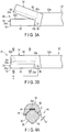
- the movable jaw 34 is rotatable around the pivot shaft 36, and movable between the position (opened position) illustrated in FIG. 3A in which the movable jaw 24 is distant from the stationary jaw 32, and the position (closed position) illustrated in FIG. 3B in which the movable jaw 24 is adjacent to the stationary jaw 32.
- the treatment section 24 also includes a first electrode (electrode member) 42 formed as the probe distal end portion (first clamp portion) 32 connected with the ultrasonic transducer 26, and a second electrode (second electrode member) 44 provided on the movable jaw 34.
- the treatment instrument main body 22 includes a switch 50.
- the first electrode 42, the second electrode 44, the ultrasonic transducer 26 and the switch 50 are electrically connected with the controller 14.
- the first electrode 42 and the second electrode 44 have different potentials.
- the switch 50 includes a first switch 52 and a second switch 54.
- the first switch 52 When the first switch 52 is pressed, a signal is input from the first switch 52 to the controller 14.
- the controller 14 controls the first and second electrodes 42 and 44 to perform bipolar high-frequency output in a seal mode. For this reason, when the first switch 52 is pressed, coagulation of the living tissue (seal of the blood vessel when the living tissue is the blood vessel) can be performed.
- the second switch 54 is pressed, a signal is input from the second switch 54 to the controller 14.
- the controller 14 performs ultrasonic output and bipolar high-frequency output in a seal & cut mode. For this reason, when the second switch 54 is pressed, coagulation and incision of the living tissue (seal and incision of the blood vessel when the living tissue is the blood vessel) .
- the treatment instrument main body 22 includes a stationary handle 23a and a movable handle 23b.
- the treatment section 24 of the treatment instrument 12 according to the present embodiment is formed in a single-swinging type.
- the movable jaw 34 is opened with respect to the stationary jaw 32, in linkage with an operation of moving the movable handle 23d of the treatment instrument main body 22 to be distant from the stationary handle 23a.
- the movable jaw 34 is closed with respect to the stationary jaw 32, in linkage with an operation of moving the movable handle 23d of the treatment instrument main body 22 to be adjacent to the stationary handle 23a.
- the movable jaw 34 is openable and closable with respect to the stationary jaw 32.
- the cross section of the stationary jaw (probe distal end portion) 32 is formed in a substantially octagonal shape.
- the stationary jaw 32 is used as the first electrode 42 to perform high-frequency output to the living tissue in cooperation with the second electrode 44.
- the movable jaw 34 includes a movable jaw main body 62 and a pressure pad (stopper) 64.
- the movable jaw main body 62 is provided with the second electrode 44 in a position opposed to the first electrode 42.
- the second electrode 44 is formed in a state of holding the pressure pad 64 therebetween.
- the movable jaw main body 62 is also preferably formed in one unitary piece with the second electrode 44.
- the pressure pad 64 is formed of a material having electric insulation property, heat resistance, and abrasion resistance.
- the pressure pad 64 is in a position that can contact a holding surface 32a of the stationary jaw 32.
- the second electrode 44 of the movable jaw 34 can be adjacent to the stationary jaw 32, that is, the first electrode 42, with clearance C.
- the stationary jaw 32 and the movable jaw 34 include distal end portions (one end portions) 33a and 35a, and proximal end portions (the other end portions) 33b and 35b, respectively.
- the proximal end portions (the other end portions) 33b and 35b are adjacent to the pivot shaft 36, and disposed in the vicinity of the most proximal end of the position in which the living tissue can be held.
- the clearance C is continuously formed from the distal end portions (one end portions) 33a and 35a of the stationary jaw 32 and the movable jaw 34 to the proximal end portions (the other end portions) 33b and 35b.
- the first and second electrodes 42 and 44 are distant from each other from the distal end portions (one end portions) 33a and 35a of the stationary jaw 32 and the movable jaw 34 to the proximal end portions (the other end portions) 33b and 35b.
- a portion between the distal end portion (one end portion) 33a and the proximal end portion (the other end portion) 33b may be straight or curved.
- a portion between the distal end portion (one end portion) 35a and the proximal end portion (the other end portion) 35b may be straight or curved.
- the explanation illustrates the case where the stationary jaw 32 and the movable jaw 34 are straight.
- the movable jaw 34 When the movable handle 23b is moved to be relatively adjacent to the stationary handle 23a of the treatment instrument main body 22, the movable jaw 34 is rotated around the pivot shaft 36 at the distal end of the treatment instrument main body 22 in linkage with the operation of the movable handle 23b, and the movable jaw 34 is moved adjacent to the stationary jaw 32.
- the movable handle 23b When the movable handle 23b is moved to be relatively distant from the stationary handle 23a, the movable jaw 34 is rotated around the pivot shaft 36 in linkage with the operation of the movable handle 23b, and the movable jaw 34 is moved distant from the stationary jaw 32.
- the stationary jaw 32 and the movable jaw 34 are formed to have a larger size in the longitudinal direction than that in the width direction.
- the maximum widths of the stationary jaw 32 and the movable jaw 34 are determined based on, for example, the internal diameter of the trocar.
- the X-axis is determined with the pivot shaft 36 as the origin O.
- the X-axis is determined toward the extending direction opposite to the treatment instrument main body 22, from the pivot shaft 36 of the movable jaw 34.
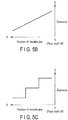
- pressure (load pressure) F applicable to the living tissue by the pressure pad 64 of the movable jaw 34 along its longitudinal direction (X-axis direction) is schematically distributed in a state illustrated in FIG. 5A .
- the load pressure F applicable to the living tissue held between the movable jaw 34 and the stationary jaw 32, that is, the load pressure F in the closed position decreases as the distance from the pivot axis 36 increases. This is considered to be caused by deflection of the movable jaw 34 and the stationary jaw 32.
- the movable jaw 34 is capable of applying a large pressure as the position becomes adjacent to the pivot shaft 36, and a small pressure as the position becomes distant from the pivot shaft 36, to the living tissue held between the movable jaw 34 and the stationary jaw 32, as illustrated in FIG. 5A .
- the treatment section 24 illustrated in FIG. 3B holds no living tissue.
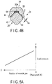
- the gap (clearance) Ca between the second electrode 44 of the movable jaw 34 illustrated in FIG. 4A and the stationary jaw 32 serving as the first electrode 42 is larger than the gap (clearance) Cb illustrated in FIG. 4B .
- the clearance C between the second electrode 44 of the movable jaw 34 and the stationary jaw 32 serving as the first electrode 42 increases as the position becomes adjacent to the pivot shaft 36, and decreases as the position becomes distant from the pivot shaft 36 along the X-axis.
- the clearance C between the second electrode 44 of the movable jaw 34 and the stationary jaw 32 serving as the first electrode 42 is formed to satisfy "Ca>Cb" .
- the clearance C is linearly (in a straight line manner) reduced from the position adjacent to the pivot shaft 36 toward the position distant from the pivot shaft 36 along the X-axis.
- the clearance Ca is, for example, substantially 0.2 mm in the position illustrated in FIG. 4A
- the clearance Cb is, for example, substantially 0.1 mm in the position illustrated in FIG. 4B .
- the clearance C (>0) larger than 0 is maintained along the X-axis, between the second electrode 44 of the movable jaw 34 and the stationary jaw 32 serving as the first electrode 42.
- the clearance C may be formed by adjusting the width in the width direction orthogonal to the X-axis in each position in the direction along the X-axis in the stationary jaw 32 serving as the first electrode 42, or adjusting the shape of the second electrode 44 of the movable jaw 34 orthogonal to the X-axis in each position in the direction along the X-axis.
- the operator properly holds the treatment instrument 12, and properly operates the movable handle 23b with respect to the stationary handle 23a, to hold the living tissue (such as a blood vessel) between the stationary jaw 32 and the movable jaw 34.
- the load pressure by the movable jaw 34 of the treatment section 24 substantially linearly decreases as the position becomes distant from the position adjacent to the pivot shaft 36 along the X-axis, as illustrated in FIG. 5A .
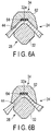
- the clearance C between the first electrode 42 of the stationary jaw 32 and the second electrode 44 of the movable jaw 34 increases as the position becomes adjacent to the pivot shaft 36, and decreases as the position becomes distant from the position adjacent to the pivot shaft 36 along the X-axis. More specifically, as illustrated in FIG. 5B , the clearance C between the stationary jaw 32 and the movable jaw 34 is formed to be narrowed from the pivot shaft 36 toward the distal end along the X-axis.
- the load pressure F of the movable jaw 34 decreases as the position becomes distant from the pivot shaft 36 along the X-axis.
- the clearance C between the first electrode 42 of the stationary jaw 32 and the second electrode 44 of the movable jaw 34 is reduced, to compensate the load pressure F to crush the living tissue.
- the clearance C in the second position distant from the pivot shaft 36 is formed smaller than that in the first position adjacent to the pivot shaft 36, to adjust the holding pressure of the stationary jaw 32 and the movable jaw 34.
- the treatment section 24 holds, for example, a blood vessel having a longitudinal direction in a direction orthogonal to the X-axis.
- the blood vessel illustrated in FIG. 6A illustrating the cross section (cross section in the first position) along line 4A-4A in FIG. 3B and the blood vessel illustrated in FIG. 6B illustrating the cross section (cross section in the second position) along line 4B-4B in FIG. 3B is crushed in the same manner.
- the crush amounts of the blood vessel illustrated in FIG. 6A and FIG. 6B are substantially the same, and the clearance C is substantially the same in the positions illustrated in FIG. 6A and FIG. 6B .
- the blood vessel When the operator presses, for example, the first switch 52, the blood vessel is sealed with high-frequency output.
- the blood vessel is held with a substantially uniform thickness as illustrated in FIG. 6A and FIG. 6B . For this reason, the blood vessel is substantially uniformly sealed from the side adjacent to the pivot shaft 36 to the side distant from the pivot shaft 36.
- the blood vessel is cut with ultrasonic output, while being sealed with high-frequency output.
- the high-frequency output and the ultrasonic output are simultaneously output to cut the blood vessel while sealing the blood vessel, the blood vessel is substantially uniformly sealed as described above. For this reason, the blood vessel is cut in a state where miss of seal hardly occurs.
- the load pressure F of the movable jaw 34 decreases along the longitudinal direction (X-axis) in the direction distant from the pivot shaft 36.
- the crushing pressure of the living tissue can be compensated by adjusting, gradually reducing in this example, the clearance C between the first electrode 42 of the stationary jaw 32 and the second electrode 44 of the movable jaw 34.
- This structure substantially equalizes the crush amount between the crush amount with which the living tissue is crushed in the position adjacent to the pivot shaft 36 and the crush amount with which the living tissue is crushed in the position distant from the pivot shaft 36 along the X-axis.
- the living tissue can be held with substantially uniform force through the whole length of the region of the held living tissue, by adjusting the clearance C.
- This structure enables exertion of substantially uniform force, regardless of the position along the X-axis, in the stationary jaw 32 and the movable jaw 34.
- This structure enables uniform input of energy between the side adjacent to the pivot shaft 36 and the side distant from the pivot shaft 36, when the high-frequency energy is output to the living tissue.
- This structure substantially equalizes the sealing capability of the living tissue such as a blood vessel, from the side adjacent to the pivot shaft 36 to the side distant from the pivot shaft along the X-axis.
- the sealing capability is substantially equalized. This structure more securely prevents occurrence of miss of seal of the blood vessel when the blood vessel is cut, and leakage of the blood.
- the living tissue when the living tissue is coagulated using high-frequency output, the living tissue can be substantially uniformly coagulated in the same manner as the blood vessel.
- the sealing capability is substantially equalized when the living tissue is cut. This structure more securely prevents occurrence of miss of coagulation of the living tissue when the living tissue is cut.
- the present embodiment illustrates the example of forming the clearance C as illustrated in FIG. 5B .
- the clearance C may preferably be reduced in a stepped manner, as the position becomes distant from the pivot shaft 36 along the X-axis.
- the holding force to the living tissue can be adjusted in accordance with the position apart from the pivot shaft 36, that is, the position with respect to the pivot shaft 36.
- the treatment section 24 is capable of changing the holding force to the living tissue in accordance with the position along the longitudinal direction.
- the method of reducing the clearance C as the position becomes distant from the pivot shaft 36 is not limited to the state illustrated in FIG. 5B or the state illustrated in FIG. 5C , but may be reduced, for example, in a parabolic manner, or in a quadric curve manner.
- the treatment instrument main body 22 illustrated in FIG. 7A and FIG. 7B includes double sheaths 22a and 22b that are concentrically arranged.
- the movable jaw 34 is supported with the pivot shaft 36 at the distal end of the inner sheath 22a of the treatment instrument main body 22.
- the movable handle 23b is operated with respect to the stationary handle 23a, the inner sheath 22a and the outer sheath 22b are relatively moved along the axial direction of the sheaths 22a and 22b. For this reason, the stationary jaw 32 and the movable jaw 34 are opened and closed as illustrated in FIG. 7A and FIG. 7B .
- the distal end of the outer sheath 22b and the proximal end of the movable jaw 34 are provided with contact sections (stoppers) 82a and 82b, respectively.
- the contact sections 82a and 82b can be separated from each other as illustrated in FIG. 7A , and can contact each other as illustrated in FIG. 7B .
- the contact sections (stoppers) 82a and 82b regulate the range in which the movable jaw 34 is rotated around the pivot shaft 36, and regulates the clearance C of the electrode 44 with respect to the electrode 42 of the stationary jaw 32.
- the clearances Ca and Cb illustrated in FIG. 4A and FIG. 4B can be adjusted by controlling the pivot amount of the movable jaw 34 with respect to the stationary jaw 32.
- the clearance C is formed along the opening/closing direction of the movable jaw 34.
- the clearance C according to the modification is preferably adjusted together with the clearance C explained in the first embodiment.
- a Y-axis is set in a direction orthogonal to a proper position along the X-axis between the pivot shaft 36 and the distal end portions 33a and 35a of the stationary jaw 32 and the movable jaw 32 in FIG. 3B .
- the pressure (load pressure) F applicable to the living tissue by the pressure pad 64 of the movable jaw 34 along a direction orthogonal to its longitudinal direction schematically distributes in a state illustrated in FIG. 9A .
- the load pressure F applicable to the living tissue held between the movable jaw 34 and the stationary jaw 32 that is, the load pressure F in the closed position decreases from the substantial center in the width direction of the stationary jaw 32 and the movable jaw 34, as it goes away from the center along the Y direction. This is considered to be caused by deflection of the movable jaw 34 and the stationary jaw 32.
- the movable jaw 34 is capable of applying a large pressure gradually increasing toward the substantial center in the width direction of the stationary jaw 32 and the movable jaw 34, and a small pressure gradually decreasing in a direction of going away from the center, to the living tissue held between the movable jaw 34 and the stationary jaw 32.
- the portion with a fixed applied pressure in the center in FIG. 9A corresponds to a portion in which the holding surface 32a of the stationary jaw 32 (first electrode 42) contacts the pressure pad 64 of the movable jaw 34 in FIG. 8 , and the portion includes the middle point M of the movable jaw 34 and the stationary jaw 32.
- the treatment section 24 illustrated in FIG. 3B holds no living tissue.
- C is the gap (clearance) between the second electrode 44 of the movable jaw 34 and the stationary jaw 32 serving as the first electrode 42 illustrated in FIG. 8 .
- C is the gap (clearance) between the second electrode 44 of the movable jaw 34 and the stationary jaw 32 serving as the first electrode 42 illustrated in FIG. 8 .
- the clearance C between the second electrode 44 of the movable jaw 34 and the stationary jaw 32 serving as the first electrode 42 is larger in a position closer to the substantial center in the width direction of the stationary jaw 32 and the movable jaw 34, and smaller in a position more distant from the substantial center in the width direction of the stationary jaw 32 and the movable jaw 34 along the Y-axis, except for the position in which the stationary jaw 32 contacts the pressure pad 64 of the movable jaw 34.
- the clearance C between the first electrode 42 of the stationary jaw 32 and the second electrode 44 of the movable jaw 34 is set to be smaller in a position more distant from the substantial center in the width direction of the stationary jaw 32 and the movable jaw 34, the load pressure F to crush the living tissue is compensated.
- substantially fixed holding force to the living tissue can be exhibited, regardless of the position along the X direction, in the stationary jaw 32 and the movable jaw 34.
- the blood vessel is substantially uniformly sealed from the substantial center to the distant sides of the stationary jaw 32 and the movable jaw 34.
- This structure substantially equalizes the sealing capability of the living tissue such as a blood vessel, from the side adjacent to the pivot shaft 36 to the side distant from the pivot shaft along the X-axis, and substantially equalizes the sealing capability from the substantial center in the width direction of the stationary jaw 32 and the movable jaw 34 to the sides distant from the center in the Y direction.
- the width of the second electrode 44 is narrowed with respect to the probe distal end portion 32, with respect to the direction along the Y-axis orthogonal to the X-axis, to reduce the clearance C from the substantial center in the width direction of the stationary jaw 32 and the movable jaw 34 gradually toward the edge portions.
- the width of the probe distal end portion is broadened with respect to the second electrode 44, with respect to the direction along the Y-axis orthogonal to the X-axis, to gradually decrease the clearance C from the substantial center in the width direction of the stationary jaw 32 and the movable jaw 34 toward the edge portions.
- the present embodiment is a modification of the first embodiment.
- Members that are the same, or having the same functions, as the members explained in the first embodiment are denoted by the same reference numerals, and detailed explanation is omitted.
- This embodiment illustrates the example of including a treatment section 24 of a double-swinging type, unlike the treatment section 24 of a single-swinging type explained in the first embodiment.
- the first embodiment illustrates the case where treatment instrument 12 is capable of performing treatment of the living tissue with ultrasonic vibration, in addition to treatment of the living tissue with high-frequency energy.
- the present embodiment illustrates the treatment instrument 12 treating the living tissue only with a high-frequency output.
- the treatment unit 10 according to the present embodiment is not provided with ultrasonic transducer 26 illustrated in FIG. 1 .
- the treatment unit 10 according to the present embodiment includes a foot switch 16 instead of the switch 50.
- the controller 14 and the foot switch 16 are detachable from each other.
- the treatment section 24 is provided in the distal end portion of the treatment instrument main body 22.
- the treatment section 24 includes a first jaw (first clamp portion) 132, and a second jaw (second clamp portion) 134 movable between a position (closed position) adjacent to the first jaw 132 and a position (opened position) distant from the first jaw 132.
- the first and the second jaws 132 and 134 are supported by a pivot shaft 136 in the vicinity of the distal end portion of the treatment instrument main body 22.
- the first and the second jaws 132 and 134 move substantially symmetrically with respect to the pivot shaft 136.
- FIG. 11A and FIG. 11B One pivot shaft 136 is illustrated in FIG. 11A and FIG. 11B in the present embodiment, but the jaws 132 and 134 may preferably be configured to rotate around respective pivot shafts (not illustrated).
- the first jaw 132 is provided with the first electrode 42
- the second jaw 134 is provided with the second electrode 44.
- the first electrode 42 and the second electrode 44 are formed in a shape of flat plates that are substantially parallel in the closed position.
- the first and the second electrodes 42 and 44 are adjacent to each other, but separated from each other.
- the distance between the first and the second electrodes 42 and 44 in the closed position gradually increases toward the pivot shaft 136, and gradually decreases in a direction of going away from the pivot shaft 136.
- the first and the second electrodes 42 and 44 are separated from each other with an electric insulating stopper 182 provided on the first electrode 42.
- the stopper 182 regulates the clearance C of the electrode 44 of the second jaw 134 with respect to the electrode 42 of the first jaw 132, in the closed position. Accordingly, the stopper 182 regulates the range in which the first and the second jaws 132 and 134 are rotated around the pivot shaft 136.
- the treatment section 24 illustrated in FIG. 11B holds no living tissue.
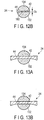
- the gap (clearance) Ca between the second electrode 44 of the second jaw 134 and the first jaw 132 serving as the first electrode 42 illustrated in FIG. 12A is larger than the gap (clearance) Cb illustrated in FIG. 12B .
- the clearance C between the first electrode 42 of the first jaw 132 and the second electrode 44 of the second jaw 134 becomes larger toward the pivot shaft 136, and smaller in a direction of going away from the pivot shaft 136 along the X-axis.
- the clearance C between the first electrode 42 of the first jaw 132 and the second electrode 44 of the second jaw 134 is formed to satisfy "Ca>Cb".
- the treatment section 24 holds, for example, blood vessels having a longitudinal direction in a direction orthogonal to the X-axis.
- the treatment section 24 crushes the blood vessel illustrated in FIG. 13A illustrating a cross section (cross section in the first position) taken along line 12A-12A in FIG. 11B
- the blood vessel illustrated in FIG. 13B illustrating a cross section (cross section in the second position) taken along line 12B-12B in FIG. 11B , in the same manner.
- the crush amounts of the blood vessels illustrated in FIG. 13A and FIG. 13B are substantially equal, and the clearances C in the positions illustrated in FIG. 13A and FIG. 13B are substantially equal in the positions.
- the blood vessels are sealed with high-frequency output.
- the blood vessels are held with a substantially uniform thickness as illustrated in FIG. 13A and FIG. 13B . For this reason, the blood vessels are substantially uniformly sealed from the side adjacent to the pivot shaft 136 to the side distant from the pivot shaft 136.
- the load pressure F between the first and the second jaws 132 and 134 reduces along the longitudinal direction (X-axis) in a direction of going away from the pivot shaft 136.
- This can be compensated, in particular, the crushing pressure of the living tissue in a position distant from the pivot shaft 136 is compensated, by adjusting the clearance C between the first and the second electrodes 42 and 44 of the first and the second jaws 132 and 134, that is, by gradually decreasing the clearance C herein.
- This structure substantially equalize the crushing amount to crush the living tissue in a position adjacent to the pivot shaft 136, and the crushing amount to crush the living tissue in a position distant from the pivot shaft 136 along the X-axis.
- the treatment instrument 12 is capable of holding the living tissue by substantially uniform force over the whole length of the region of the held living tissue, by adjusting the clearance C.
- This structure enables exhibition of substantially fixed holding force to the living tissue, regardless of the position along the X-axis, in the first jaw 132 and the second jaw 134. Accordingly, when high-frequency energy is output to the living tissue, the energy can be uniformly input between the side adjacent to the pivot shaft 136 and the side distant from the pivot shaft 136.
- This structure substantially equalize the sealing capability of the living tissue such as a blood vessel, from the side adjacent to the pivot shaft 136 to the side distant from the pivot shaft 136 along the X-axis.
- this structure enables substantially uniform coagulation, in the same manner as blood vessels.
- the present embodiment illustrates the case where the treatment section 24 is of a double-swinging type.
- the treatment section 24 may be of a single-swinging type.
- the insulating stopper 182 is provided on at least one of the first and the second electrodes 42 and 44.
- the stoppers 82a may be formed between the first jaw 132 and the treatment instrument main body 22, and between the second jaw 134 and the treatment instrument main body 22.
- the treatment instrument 12 is explained as a treatment instrument capable of outputting high-frequency output and ultrasonic output, in the same manner as explained in the first embodiment.
- the treatment instrument 12 may be configured to be capable of outputting only high-frequency output, as a matter of course.
- the treatment section 24 includes the stationary jaw (first clamp portion) 32, a movable jaw 234, and a pivot member (second clamp portion) 236.
- the movable jaw 234 is supported by the treatment instrument main body 22, more specifically, the pivot shaft (second pivot shaft) 36 at the distal end of the sheath 22a, in the same manner as the movable jaw 34 explained in the first embodiment.
- the pivot member 236 is supported by the movable jaw 234 with a pivot shaft (first pivot shaft) 238 as a fulcrum.
- the pivot member 236 is located in a position more adjacent to the fix jaw 32 beyond the movable jaw 234.
- the pivot shafts 236 and 238 are preferably parallel with each other.
- the movable jaw 234 and the pivot member 236 move in linkage with each other, and are referred to as seesaw jaws or wiper jaws.
- the movable jaw 234 is provided between the two pivot shafts 36 and 238, and capable of rotating the pivot member 236 with its pivot around the pivot shaft 36, and moving the pivot member 236 between the opened position and the closed position.
- the pivot member 236 is movable between the position (opened position) illustrated in FIG. 14A in which the pivot member 236 is distant from the stationary jaw 32, and the position (closed position) illustrated in FIG. 14B in which the pivot member 236 is adjacent to the stationary jaw 32, with pivot of the movable jaw 234.
- the pivot member 236 includes a pivot member main body 262, and the pressure pad (stopper) 64.
- the pivot member main body 262 is provided with the second electrode 44 in a position opposed to the first electrode 42 (stationary jaw 32).
- the second electrode 44 is formed in a state of holding the pressure pad 64 therebetween.
- the pivot member main body 262 may preferably be formed as one unitary piece with the second electrode 44.
- the pressure pad 64 is located in a position contacting the stationary jaw 32.
- the second electrode 44 of the pivot member 236 can be disposed adjacent to the stationary jaw 32, that is, the first electrode 42, with the clearance C.
- the stationary jaw 32 and the pivot member 262 include distal end portions (one end portions) 33a and 236a and proximal end portions (other end portions) 33b and 236b, respectively.
- the proximal end portions (the other end portions) 33b and 236b are located adjacent to the pivot shaft 36, and in the vicinity of the most proximal end in the position where the living tissue can be held.
- the clearance C is formed in a state of continuously extending from the distal end portions (one end portions) 33a and 236a of the stationary jaw 32 and the pivot member 236 to the proximal end portions (the other end portions) 33b and 236b.
- first and the second electrodes 42 and 44 are separated from each other from the distal end portions (one end portions) 33a and 236a of the stationary jaw 32 and the pivot member 236 to the proximal end portions (the other end portions) 33b and 236b, in the state where the pivot member 236 is in the closed position with respect to the stationary jaw 32.
- the movable jaw 234 When the movable handle 23b is relatively positioned adjacent to the stationary handle 23a of the treatment instrument main body 22, the movable jaw 234 is rotated around the pivot shaft 36 at the distal end of the treatment instrument main body 22, in linkage with the operation of the movable handle 23b, and the pivot member 236 supported by the movable jaw 234 is positioned adjacent to the stationary jaw 32.
- the movable handle 23b When the movable handle 23b is relatively positioned distant from the stationary handle 23a, the movable jaw 234 is rotated around the pivot shaft 36, in linkage with the operation of the movable handle 23b, and the pivot member 236 supported by the movable jaw 234 is positioned distant from the stationary jaw 32, together with the movable jaw 234.
- the stationary jaw 32, the movable jaw 234, and the pivot member 236 have longitudinal sizes larger than their sizes in the width direction.
- the maximum widths of the stationary jaw 32, the movable jaw 234, and the pivot member 236 are determined, for example, based on relation with the internal diameter of the trocar.
- an X-axis is set with the pivot shaft 36 serving as the origin O.
- the X-axis is set to extend from the pivot shaft 36 of the movable jaw 234 in an extending direction opposite to the treatment instrument main body 22.
- the pressure (load pressure) F applicable to the living tissue by the pivot member 236 of the movable jaw 34 along its longitudinal direction (X-axis direction) schematically distributes in a state illustrated in FIG. 16A .
- the pivot member 236 supported by the movable jaw 234 is closed with respect to the stationary jaw 32, as illustrated in FIG.
- the pivot member 236 supported by the movable jaw 234 is capable of applying larger pressure to the living tissue held between it and the stationary jaw 32, in a position more adjacent to the pivot shaft 238. For this reason, the pivot member 236 supported by the movable jaw 234 decreases the force applied to the living tissue held between it and the stationary jaw 32, as the position becomes distant from the pivot shaft 238.
- the treatment section 24 illustrated in FIG. 14B holds no living tissue.
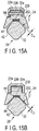
- the gap (clearance) C ⁇ between the second electrode 44 of the pivot member 236 supported by the movable jaw 34 and the stationary jaw 32 serving as the first electrode 42 illustrated in FIG. 15A is larger than the gap (clearance) C ⁇ illustrated in FIG. 15B , and the gap (clearance) C ⁇ illustrated in FIG. 15C .
- the gap (clearance) C ⁇ illustrated in FIG. 15C As illustrated in FIG.
- the clearance C between the second electrode 44 of the pivot member 236 according to the present embodiment and the stationary jaw 32 serving as the first electrode 42 is larger in a position closer to the pivot shaft 238 of the pivot member 236, and smaller in a position more distant from the pivot shaft 238 along the X-axis.
- the clearance C between the second electrode 44 of the pivot member 236 and the stationary jaw 32 serving as the first electrode 42 is formed to satisfy "C ⁇ >C ⁇ " and "C ⁇ >C ⁇ ".
- the clearance C is set to be linearly (in a straight line manner) smaller from the position adjacent to the pivot shaft 238 toward the position distant from the pivot shaft 238 along the X-axis.
- the clearance C ⁇ is approximately 0.2 mm in the position illustrated in FIG. 15A
- the clearance C ⁇ is approximately 0.1 mm in the position illustrated in FIG. 15B
- the clearance C ⁇ is approximately 0.1 mm in the position illustrated in FIG. 15C .
- the clearance C larger than 0 (C>0) is maintained along the X-axis between the second electrode 44 of the movable jaw 234 and the stationary jaw 32 serving as the first electrode 42.
- the treatment section 24 holds, for example, blood vessels having a longitudinal direction in a direction orthogonal to the X-axis.
- the treatment section 24 crushes the blood vessel illustrated in FIG. 17A illustrating a cross section (cross section in the first position) taken along line 15A-15A in FIG. 14B
- the blood vessel illustrated in FIG. 17B illustrating a cross section (cross section in the second position) taken along line 15B-15B in FIG. 14B
- the blood vessel illustrated in FIG. 17C illustrating a cross section (cross section in the third position) taken along line 15C-15C in FIG. 14B , in the same manner.
- the crush amounts of the blood vessels illustrated in FIG. 17A to FIG. 17C are substantially equal
- the clearance C is substantially equal in the positions illustrated in FIG. 17A to FIG. 17C .
- the blood vessels are sealed with high-frequency output.
- the blood vessels are held with a substantially uniform thickness as illustrated in FIG. 17A to FIG. 17C .
- the blood vessels are substantially uniformly sealed in any position from the distal end portion 236a to the proximal end portion 236b of the pivot member 236.
- the blood vessels are cut by ultrasonic output, while being sealed by high-frequency output.
- the high-frequency output and the ultrasonic output are simultaneously output to cut the blood vessels while the blood vessels are sealed, the blood vessels are substantially uniformly sealed as described above. For this reason, the blood vessels are cut in a state in which miss of seal hardly occurs.
- the load pressure F of the pivot member 236 reduces along the longitudinal direction (X-axis) in a direction of going away from the pivot shaft 238.
- the crushing pressure of the living tissue is compensated, by adjusting the clearance C between the first electrode 42 of the stationary jaw 32 and the second electrode 44 of the pivot member 236, that is, by gradually decreasing the clearance C herein.
- This structure substantially equalize the crushing amount to crush the living tissue in a position adjacent to the pivot shaft 238, and the crushing amount to crush the living tissue in a position distant from the pivot shaft 238 along the X-axis.
- the treatment instrument 12 is capable of holding the living tissue by substantially uniform force over the whole length of the region of the held living tissue, by adjusting the clearance C.
- This structure enables exhibition of substantially fixed holding force to the living tissue, regardless of the position along the X-axis, in the first jaw 32 and the pivot member 236. Accordingly, when high-frequency energy is output to the living tissue, the energy can be uniformly input between the side adjacent to the pivot shaft 238 and the side distant from the pivot shaft 238.
- This structure substantially equalize the sealing capability of the living tissue such as a blood vessel, from the side adjacent to the pivot shaft 238 to the side distant from the pivot shaft 238 along the X-axis.
- the sealing capability is substantially made uniform. This structure more securely prevents occurrence of miss of seal for a blood vessel in cutting the blood vessel, and prevents discharge of the blood.
- this structure enables substantially uniform coagulation, in the same manner as blood vessels.
- the sealing capability is substantially made uniform. This structure more securely prevents occurrence of miss of coagulation for a living tissue in cutting the living tissue.
- the present embodiment illustrates the example of forming the clearance C as illustrated in FIG. 16B .
- the clearance C may be preferably reduced in a stepped manner, as the position becomes distant from the pivot shaft 238 along the X-axis.
- the holding force to the living tissue can be adjusted in accordance with the position separated from the pivot shaft 238, that is, the position with respect to the pivot shaft 238.
- This structure enables the treatment section 24 to change the holding force to the living tissue in accordance with the position along the longitudinal direction.
- the clearance C may be formed by adjusting the width between the probe distal end portion 32 and the second electrode 44 along the Y-axis direction orthogonal to the X-axis, or may be formed by adjusting the width of the probe distal end portion 32 along the Y-axis direction orthogonal to the X-axis with respect to the second electrode 44.
- the width of the second electrode 44 is narrowed with respect to the probe distal end portion 32 with respect to the direction along the Y-axis direction orthogonal to the X-axis, to reduce the clearance C gradually from the center side toward the edge portion sides.
- the width of the probe distal end portion 32 is broadened with respect to the second electrode 44 with respect to the direction along the Y-axis direction orthogonal to the X-axis, to reduce the clearance C gradually from the center side toward the edge portion sides.
- the reducing mechanism of the clearance C as the position becomes more distant from the pivot shaft 238 is not limited to the state illustrated in FIG. 16B or the state illustrated in FIG. 16C .
- the double-swinging type first jaw 132 illustrated in FIG. 11A and FIG. 11B explained in the second embodiment can be provided with the pivot shaft 238 to rotatably support the pivot member 236, and the second jaw 134 can be provided with the pivot shaft 238 to rotatably support the pivot member 236.
- the pivot members 236 are opposed to each other.
Landscapes
- Health & Medical Sciences (AREA)
- Life Sciences & Earth Sciences (AREA)
- Engineering & Computer Science (AREA)
- Surgery (AREA)
- Animal Behavior & Ethology (AREA)
- Veterinary Medicine (AREA)
- Nuclear Medicine, Radiotherapy & Molecular Imaging (AREA)
- Public Health (AREA)
- Biomedical Technology (AREA)
- General Health & Medical Sciences (AREA)
- Medical Informatics (AREA)
- Molecular Biology (AREA)
- Heart & Thoracic Surgery (AREA)
- Physics & Mathematics (AREA)
- Otolaryngology (AREA)
- Plasma & Fusion (AREA)
- Dentistry (AREA)
- Mechanical Engineering (AREA)
- Surgical Instruments (AREA)
- Oral & Maxillofacial Surgery (AREA)
- Pathology (AREA)
- Radiology & Medical Imaging (AREA)
Abstract

Description
- The present invention relates to a medical apparatus holding a living tissue to perform treatment.
- For example, as disclosed in
US 2009/088667 A1 , a medical apparatus is disclosed with a structure in which a second clamp portion movable with respect to a first clamp portion is rotated with a pivot shaft serving as a fulcrum, to apply a load pressure to a living tissue of various types and hold the living tissue. - The load pressure of the second clamp portion is gradually decreased as the distance from the pivot shaft increases, due to deflection of the second clamp portion and the like. For this reason, for example, when a blood vessel is held, the crush degree of the blood vessel may differ between the side adjacent to the pivot shaft and the side distant from the pivot shaft. In such a state, for example, when treatment is performed using high-frequency energy, unevenness in treatment may occur, for example, the side distant from the pivot shaft may require more time for treatment to coagulate and seal the living tissue than the time required by the side adjacent to the pivot shaft.
- The first and second clamp portions may be required to adjust the holding force regardless of the load pressure, in accordance with the position along the longitudinal direction.
- An object of the present invention is to provide a medical apparatus capable of adjusting the holding force in accordance with the position with respect to the pivot shaft, and performing desired treatment.
- According to one aspect of the present invention, a medical apparatus includes a first clamp portion; a pivot shaft; a second clamp portion rotatable around the pivot shaft, and movable between an opened position in which the second clamp portion is distant from the first clamp portion, and a closed position in which the second clamp portion is adjacent to the first clamp portion; and an electrode member provided on the second clamp portion, and opposed to the first clamp portion, the electrode member forming a clearance in cooperation with the first clamp portion in the closed position, the clearance in a second position distant from the pivot shaft being smaller than the clearance in a first position adjacent to the pivot shaft, to adjust holding pressure.
-
-
FIG. 1 is a schematic block diagram illustrating a medical apparatus unit according to a first embodiment; -
FIG. 2 is a schematic diagram illustrating a treatment instrument (medical apparatus) of the medical apparatus unit according to the first embodiment; -
FIG. 3A is a schematic diagram illustrating a state of an opened position in which a movable jaw (clamp portion) is opened with respect to a stationary jaw (clamp portion) of the treatment instrument of the medical apparatus unit according to the first embodiment; -
FIG. 3B is a schematic diagram illustrating a state of a closed position in which the movable jaw is closed with respect to the stationary jaw of the treatment instrument of the medical apparatus unit according to the first embodiment; -
FIG. 4A is a schematic lateral cross-sectional view in a position alongline 4A-4A inFIG. 3B ; -
FIG. 4B is a schematic lateral cross-sectional view in a position alongline 4B-4B inFIG. 3B ; -
FIG. 5A is a schematic diagram illustrating load pressure with respect to the position of the movable jaw at the time when the load pressure is to be applied to the living tissue, in a state where the movable jaw is rotated to the closed position with the pivot shaft of the treatment instrument according to the first embodiment serving as the fulcrum; -
FIG. 5B is a schematic diagram illustrating a size of clearance from the stationary jaw with respect to the position of the movable jaw, in the state where the movable jaw is rotated to the closed position with the pivot shaft of the treatment instrument according to the first embodiment serving as the fulcrum; -
FIG. 5C is a schematic diagram illustrating a size of clearance from the stationary jaw with respect to the position of the movable jaw, in the state where the movable jaw is rotated to the closed position with the pivot shaft of the treatment instrument according to a modification of the first embodiment serving as the fulcrum; -
FIG. 6A is a schematic lateral cross-sectional view illustrating a state where the living tissue is held in the position alongline 4A-4A inFIG. 3B ; -
FIG. 6B is a schematic lateral cross-sectional view illustrating a state where the living tissue is held in the position alongline 4B-4B inFIG. 3B ; -
FIG. 7A is a schematic diagram illustrating a state of the opened position in which the movable jaw is opened with respect to the stationary jaw of the treatment instrument of the medical apparatus unit according to a first modification of the first embodiment; -
FIG. 7B is a schematic diagram illustrating a state of the closed position in which the movable jaw is closed with respect to the stationary jaw of the treatment instrument of the medical apparatus unit according to the first modification of the first embodiment; -
FIG. 8 is a schematic lateral cross-sectional view in the position alongline 4A-4A inFIG. 3B ; -
FIG. 9A is a schematic diagram illustrating load pressure with respect to the position of the movable jaw at the time when the load pressure is to be applied to the living tissue, in a state where the movable jaw is rotated to the closed position with the pivot shaft of the treatment instrument according to the first modification of the first embodiment serving as the fulcrum; -
FIG. 9B is a schematic diagram illustrating a size of clearance from the stationary jaw with respect to the position of the movable jaw, in the state where the movable jaw is rotated to the closed position with the pivot shaft of the treatment instrument according to the first modification of the first embodiment serving as the fulcrum; -
FIG. 10 is a schematic block diagram illustrating a medical apparatus unit according to a second embodiment; -
FIG. 11A is a schematic diagram illustrating a state of an opened position in which first and second jaws (clamp portions) of a treatment instrument of the medical apparatus unit according to the second embodiment are opened; -
FIG. 11B is a schematic diagram illustrating a state of an closed position in which the first and second jaws of the treatment instrument of the medical apparatus unit according to the second embodiment are closed; -
FIG. 12A is a schematic lateral cross-sectional view in a position alongline 12A-12A inFIG. 11B ; -
FIG. 12B is a schematic lateral cross-sectional view in a position alongline 12B-12B inFIG. 11B ; -
FIG. 13A is a schematic lateral cross-sectional view illustrating a state where the living tissue is held in the position alongline 12A-12A inFIG. 11B ; -
FIG. 13B is a schematic lateral cross-sectional view illustrating a state where the living tissue is held in the position alongline 12B-12B inFIG. 11B ; -
FIG. 14A is a schematic diagram illustrating a state of an opened position in which a movable jaw of a treatment instrument of a medical apparatus unit according to a third embodiment is opened, to open a pivotal member (clamp portion) linked with the movable jaw with respect to the stationary jaw; -
FIG. 14B is a schematic diagram illustrating a state of an closed position in which the movable jaw of the treatment instrument of the medical apparatus unit according to the third embodiment is closed, to close the pivotal member linked with the movable jaw with respect to the stationary jaw; -
FIG. 15A is a schematic lateral cross-sectional view in a position alongline 15A-15A inFIG. 14B ; -
FIG. 15B is a schematic lateral cross-sectional view in a position alongline 15B-15B inFIG. 14B ; -
FIG. 15C is a schematic lateral cross-sectional view in a position alongline 15C-15C inFIG. 14B ; -
FIG. 16A is a schematic diagram illustrating load pressure with respect to the position of the pivotal member at the time when the load pressure is to be applied to the living tissue, in a state where the pivotal member (clamp portion) of the treatment instrument according to the third embodiment is rotated to the closed position; -
FIG. 16B is a schematic diagram illustrating a size of clearance from the stationary jaw with respect to the position of the pivotal member, in the state where the pivotal member of the treatment instrument according to the third embodiment is rotated to the closed position; -
FIG. 16C is a schematic diagram illustrating a size of clearance from the stationary jaw with respect to the position of the pivotal member, in the state where the pivotal member of the treatment instrument according to a modification of the third embodiment is rotated to the closed position; -
FIG. 17A is a schematic lateral cross-sectional view illustrating a state where the living tissue is held in the position alongline 15A-15A inFIG. 14B ; -
FIG. 17B is a schematic lateral cross-sectional view illustrating a state where the living tissue is held in the position alongline 15B-15B inFIG. 14B ; and -
FIG. 17C is a schematic lateral cross-sectional view illustrating a state where the living tissue is held in the position alongline 15C-15C inFIG. 14B . - Embodiments of the present invention will be explained hereinafter with reference to drawings.
- A first embodiment will be explained hereinafter with reference to
FIG. 1 to FIG. 6B . - As illustrated in
FIG. 1 , atreatment unit 10 according to the present embodiment includes a treatment instrument (medical apparatus) 12, and acontroller 14 including a power supply. Thetreatment instrument 12 and thecontroller 14 are preferably detachable. - As illustrated in
FIG. 2 , thetreatment instrument 12 includes a treatment instrumentmain body 22, and a treatment section (end effector) 24. Thetreatment instrument 12 further includes anultrasonic transducer 26 that is preferably attachable to and detachable from the treatment instrumentmain body 22. Theultrasonic transducer 26 is connected with an ultrasonic probe (vibration transmission member) 28 capable of transmitting ultrasonic vibration generated in theultrasonic transducer 26. Theultrasonic probe 28 is formed of a material having conductivity, such as titanium alloy and the like. The distal end portion (probe distal end portion) of theultrasonic probe 28 projects from the distal end of the treatment instrumentmain body 22, and is used as astationary jaw 32 described later. - As illustrated in
FIG. 3A and FIG. 3B , thetreatment section 24 includes the stationary jaw (first clamp portion) 32 and a movable jaw (second clamp portion) 34. Themovable jaw 34 is movable between an opened position in which themovable jaw 34 is distant from thestationary jaw 32, and a closed position in which themovable jaw 34 is adjacent to thestationary jaw 32. - The
movable jaw 34 is supported by the treatment instrumentmain body 22. More specially, themovable jaw 34 is supported by apivot shaft 36 at the distal end of asheath 22a. Themovable jaw 34 is rotatable around thepivot shaft 36, and movable between the position (opened position) illustrated inFIG. 3A in which themovable jaw 24 is distant from thestationary jaw 32, and the position (closed position) illustrated inFIG. 3B in which themovable jaw 24 is adjacent to thestationary jaw 32. Thetreatment section 24 also includes a first electrode (electrode member) 42 formed as the probe distal end portion (first clamp portion) 32 connected with theultrasonic transducer 26, and a second electrode (second electrode member) 44 provided on themovable jaw 34. As illustrated inFIG. 1 , the treatment instrumentmain body 22 includes aswitch 50. Thefirst electrode 42, thesecond electrode 44, theultrasonic transducer 26 and theswitch 50 are electrically connected with thecontroller 14. Thefirst electrode 42 and thesecond electrode 44 have different potentials. - As illustrated in
FIG. 2 , in the present embodiment, theswitch 50 includes afirst switch 52 and asecond switch 54. When thefirst switch 52 is pressed, a signal is input from thefirst switch 52 to thecontroller 14. At the time, thecontroller 14 controls the first andsecond electrodes first switch 52 is pressed, coagulation of the living tissue (seal of the blood vessel when the living tissue is the blood vessel) can be performed. When thesecond switch 54 is pressed, a signal is input from thesecond switch 54 to thecontroller 14. At the time, thecontroller 14 performs ultrasonic output and bipolar high-frequency output in a seal & cut mode. For this reason, when thesecond switch 54 is pressed, coagulation and incision of the living tissue (seal and incision of the blood vessel when the living tissue is the blood vessel) . - As illustrated in
FIG. 2 , the treatment instrumentmain body 22 includes astationary handle 23a and amovable handle 23b. Thetreatment section 24 of thetreatment instrument 12 according to the present embodiment is formed in a single-swinging type. Themovable jaw 34 is opened with respect to thestationary jaw 32, in linkage with an operation of moving the movable handle 23d of the treatment instrumentmain body 22 to be distant from thestationary handle 23a. Themovable jaw 34 is closed with respect to thestationary jaw 32, in linkage with an operation of moving the movable handle 23d of the treatment instrumentmain body 22 to be adjacent to thestationary handle 23a. Specifically, in thetreatment section 24, themovable jaw 34 is openable and closable with respect to thestationary jaw 32. By closing themovable jaw 34 with respect to thestationary jaw 32, the living tissue is held between thestationary jaw 32 and themovable jaw 34. A publicly-known mechanism of various types may be properly used as the mechanism to open and close themovable jaw 34 with respect to thestationary jaw 32, and explanation thereof is omitted herein. - As illustrated in
FIG. 4A andFIG. 4B , the cross section of the stationary jaw (probe distal end portion) 32 is formed in a substantially octagonal shape. Thestationary jaw 32 is used as thefirst electrode 42 to perform high-frequency output to the living tissue in cooperation with thesecond electrode 44. - The
movable jaw 34 includes a movable jawmain body 62 and a pressure pad (stopper) 64. The movable jawmain body 62 is provided with thesecond electrode 44 in a position opposed to thefirst electrode 42. Thesecond electrode 44 is formed in a state of holding thepressure pad 64 therebetween. The movable jawmain body 62 is also preferably formed in one unitary piece with thesecond electrode 44. Thepressure pad 64 is formed of a material having electric insulation property, heat resistance, and abrasion resistance. Thepressure pad 64 is in a position that can contact a holdingsurface 32a of thestationary jaw 32. By contrast, thesecond electrode 44 of themovable jaw 34 can be adjacent to thestationary jaw 32, that is, thefirst electrode 42, with clearance C. - The
stationary jaw 32 and themovable jaw 34 include distal end portions (one end portions) 33a and 35a, and proximal end portions (the other end portions) 33b and 35b, respectively. The proximal end portions (the other end portions) 33b and 35b are adjacent to thepivot shaft 36, and disposed in the vicinity of the most proximal end of the position in which the living tissue can be held. The clearance C is continuously formed from the distal end portions (one end portions) 33a and 35a of thestationary jaw 32 and themovable jaw 34 to the proximal end portions (the other end portions) 33b and 35b. Specifically, in the state where themovable jaw 34 is in the closed position with respect to thestationary jaw 32, the first andsecond electrodes stationary jaw 32 and themovable jaw 34 to the proximal end portions (the other end portions) 33b and 35b. In thestationary jaw 32, a portion between the distal end portion (one end portion) 33a and the proximal end portion (the other end portion) 33b may be straight or curved. In themovable jaw 34, a portion between the distal end portion (one end portion) 35a and the proximal end portion (the other end portion) 35b may be straight or curved. In this example, to simplify the explanation, the explanation illustrates the case where thestationary jaw 32 and themovable jaw 34 are straight. - When the
movable handle 23b is moved to be relatively adjacent to thestationary handle 23a of the treatment instrumentmain body 22, themovable jaw 34 is rotated around thepivot shaft 36 at the distal end of the treatment instrumentmain body 22 in linkage with the operation of themovable handle 23b, and themovable jaw 34 is moved adjacent to thestationary jaw 32. When themovable handle 23b is moved to be relatively distant from thestationary handle 23a, themovable jaw 34 is rotated around thepivot shaft 36 in linkage with the operation of themovable handle 23b, and themovable jaw 34 is moved distant from thestationary jaw 32. - The
stationary jaw 32 and themovable jaw 34 are formed to have a larger size in the longitudinal direction than that in the width direction. The maximum widths of thestationary jaw 32 and themovable jaw 34 are determined based on, for example, the internal diameter of the trocar. - As illustrated in
FIG. 3B , the X-axis is determined with thepivot shaft 36 as the origin O. In particular, the X-axis is determined toward the extending direction opposite to the treatment instrumentmain body 22, from thepivot shaft 36 of themovable jaw 34. - In the state of the closed position in which the
movable jaw 34 is adjacent to thestationary jaw 32, pressure (load pressure) F applicable to the living tissue by thepressure pad 64 of themovable jaw 34 along its longitudinal direction (X-axis direction) is schematically distributed in a state illustrated inFIG. 5A . The load pressure F applicable to the living tissue held between themovable jaw 34 and thestationary jaw 32, that is, the load pressure F in the closed position decreases as the distance from thepivot axis 36 increases. This is considered to be caused by deflection of themovable jaw 34 and thestationary jaw 32. For this reason, in the state where themovable jaw 34 is closed with respect to thestationary jaw 32, themovable jaw 34 is capable of applying a large pressure as the position becomes adjacent to thepivot shaft 36, and a small pressure as the position becomes distant from thepivot shaft 36, to the living tissue held between themovable jaw 34 and thestationary jaw 32, as illustrated inFIG. 5A . - The
treatment section 24 illustrated inFIG. 3B holds no living tissue. In this state, in the state where themovable jaw 34 is closed with respect to thestationary jaw 32, the gap (clearance) Ca between thesecond electrode 44 of themovable jaw 34 illustrated inFIG. 4A and thestationary jaw 32 serving as thefirst electrode 42 is larger than the gap (clearance) Cb illustrated inFIG. 4B . As illustrated inFIG. 5B , the clearance C between thesecond electrode 44 of themovable jaw 34 and thestationary jaw 32 serving as thefirst electrode 42 according to the present embodiment increases as the position becomes adjacent to thepivot shaft 36, and decreases as the position becomes distant from thepivot shaft 36 along the X-axis. Specifically, the clearance C between thesecond electrode 44 of themovable jaw 34 and thestationary jaw 32 serving as thefirst electrode 42 is formed to satisfy "Ca>Cb" . - As illustrated in
FIG. 5B , the clearance C is linearly (in a straight line manner) reduced from the position adjacent to thepivot shaft 36 toward the position distant from thepivot shaft 36 along the X-axis. For example, the clearance Ca is, for example, substantially 0.2 mm in the position illustrated inFIG. 4A , and the clearance Cb is, for example, substantially 0.1 mm in the position illustrated inFIG. 4B . The clearance C (>0) larger than 0 is maintained along the X-axis, between thesecond electrode 44 of themovable jaw 34 and thestationary jaw 32 serving as thefirst electrode 42. - The clearance C may be formed by adjusting the width in the width direction orthogonal to the X-axis in each position in the direction along the X-axis in the
stationary jaw 32 serving as thefirst electrode 42, or adjusting the shape of thesecond electrode 44 of themovable jaw 34 orthogonal to the X-axis in each position in the direction along the X-axis. - The following is explanation of operations of the
treatment instrument 12 according to the present embodiment. - The operator properly holds the
treatment instrument 12, and properly operates themovable handle 23b with respect to thestationary handle 23a, to hold the living tissue (such as a blood vessel) between thestationary jaw 32 and themovable jaw 34. - In this state, the load pressure by the
movable jaw 34 of thetreatment section 24 substantially linearly decreases as the position becomes distant from the position adjacent to thepivot shaft 36 along the X-axis, as illustrated inFIG. 5A . As illustrated inFIG. 4A ,FIG. 4B , andFIG. 5B , the clearance C between thefirst electrode 42 of thestationary jaw 32 and thesecond electrode 44 of themovable jaw 34 increases as the position becomes adjacent to thepivot shaft 36, and decreases as the position becomes distant from the position adjacent to thepivot shaft 36 along the X-axis. More specifically, as illustrated inFIG. 5B , the clearance C between thestationary jaw 32 and themovable jaw 34 is formed to be narrowed from thepivot shaft 36 toward the distal end along the X-axis. For this reason, the load pressure F of themovable jaw 34 decreases as the position becomes distant from thepivot shaft 36 along the X-axis. However, the clearance C between thefirst electrode 42 of thestationary jaw 32 and thesecond electrode 44 of themovable jaw 34 is reduced, to compensate the load pressure F to crush the living tissue. For this reason, the clearance C in the second position distant from thepivot shaft 36 is formed smaller than that in the first position adjacent to thepivot shaft 36, to adjust the holding pressure of thestationary jaw 32 and themovable jaw 34. - The
treatment section 24 holds, for example, a blood vessel having a longitudinal direction in a direction orthogonal to the X-axis. In this state, the blood vessel illustrated inFIG. 6A illustrating the cross section (cross section in the first position) alongline 4A-4A inFIG. 3B and the blood vessel illustrated inFIG. 6B illustrating the cross section (cross section in the second position) alongline 4B-4B inFIG. 3B is crushed in the same manner. In this state, the crush amounts of the blood vessel illustrated inFIG. 6A and FIG. 6B are substantially the same, and the clearance C is substantially the same in the positions illustrated inFIG. 6A and FIG. 6B . - When the operator presses, for example, the
first switch 52, the blood vessel is sealed with high-frequency output. When the blood vessel is sealed with high-frequency output, the blood vessel is held with a substantially uniform thickness as illustrated inFIG. 6A and FIG. 6B . For this reason, the blood vessel is substantially uniformly sealed from the side adjacent to thepivot shaft 36 to the side distant from thepivot shaft 36. - By contrast, when the operator presses, for example, the
second switch 54, the blood vessel is cut with ultrasonic output, while being sealed with high-frequency output. When the high-frequency output and the ultrasonic output are simultaneously output to cut the blood vessel while sealing the blood vessel, the blood vessel is substantially uniformly sealed as described above. For this reason, the blood vessel is cut in a state where miss of seal hardly occurs. - As described above, the following can be said with the
treatment instrument 12 according to the present embodiment. - The load pressure F of the
movable jaw 34 decreases along the longitudinal direction (X-axis) in the direction distant from thepivot shaft 36. The crushing pressure of the living tissue can be compensated by adjusting, gradually reducing in this example, the clearance C between thefirst electrode 42 of thestationary jaw 32 and thesecond electrode 44 of themovable jaw 34. This structure substantially equalizes the crush amount between the crush amount with which the living tissue is crushed in the position adjacent to thepivot shaft 36 and the crush amount with which the living tissue is crushed in the position distant from thepivot shaft 36 along the X-axis. Specifically, even when the load pressure F applied to the living tissue held between thestationary jaw 32 and themovable jaw 34 differs along the X-axis, the living tissue can be held with substantially uniform force through the whole length of the region of the held living tissue, by adjusting the clearance C. This structure enables exertion of substantially uniform force, regardless of the position along the X-axis, in thestationary jaw 32 and themovable jaw 34. This structure enables uniform input of energy between the side adjacent to thepivot shaft 36 and the side distant from thepivot shaft 36, when the high-frequency energy is output to the living tissue. This structure substantially equalizes the sealing capability of the living tissue such as a blood vessel, from the side adjacent to thepivot shaft 36 to the side distant from the pivot shaft along the X-axis. - In addition, when the living tissue such as a blood vessel is cut, the sealing capability is substantially equalized. This structure more securely prevents occurrence of miss of seal of the blood vessel when the blood vessel is cut, and leakage of the blood.
- Also when the living tissue is coagulated using high-frequency output, the living tissue can be substantially uniformly coagulated in the same manner as the blood vessel. In addition, the sealing capability is substantially equalized when the living tissue is cut. This structure more securely prevents occurrence of miss of coagulation of the living tissue when the living tissue is cut.
- The present embodiment illustrates the example of forming the clearance C as illustrated in
FIG. 5B . As another example, as illustrated inFIG. 5C , the clearance C may preferably be reduced in a stepped manner, as the position becomes distant from thepivot shaft 36 along the X-axis. - In this case, the holding force to the living tissue can be adjusted in accordance with the position apart from the
pivot shaft 36, that is, the position with respect to thepivot shaft 36. For this reason, thetreatment section 24 is capable of changing the holding force to the living tissue in accordance with the position along the longitudinal direction. - The method of reducing the clearance C as the position becomes distant from the
pivot shaft 36 is not limited to the state illustrated inFIG. 5B or the state illustrated inFIG. 5C , but may be reduced, for example, in a parabolic manner, or in a quadric curve manner. - The following is explanation of a first modification of the first embodiment with reference to
FIG. 7A and FIG. 7B . - The treatment instrument
main body 22 illustrated inFIG. 7A and FIG. 7B includesdouble sheaths movable jaw 34 is supported with thepivot shaft 36 at the distal end of theinner sheath 22a of the treatment instrumentmain body 22. By themovable handle 23b is operated with respect to thestationary handle 23a, theinner sheath 22a and theouter sheath 22b are relatively moved along the axial direction of thesheaths stationary jaw 32 and themovable jaw 34 are opened and closed as illustrated inFIG. 7A and FIG. 7B . - The distal end of the
outer sheath 22b and the proximal end of themovable jaw 34 are provided with contact sections (stoppers) 82a and 82b, respectively. Thecontact sections FIG. 7A , and can contact each other as illustrated inFIG. 7B . The contact sections (stoppers) 82a and 82b regulate the range in which themovable jaw 34 is rotated around thepivot shaft 36, and regulates the clearance C of theelectrode 44 with respect to theelectrode 42 of thestationary jaw 32. - For this reason, in the closed state illustrated in
FIG. 7B , the clearances Ca and Cb illustrated inFIG. 4A andFIG. 4B can be adjusted by controlling the pivot amount of themovable jaw 34 with respect to thestationary jaw 32. - When the
stationary jaw 32 is not used as theultrasonic probe 28 but used as the high-frequency electrode 42, the clearance C is formed along the opening/closing direction of themovable jaw 34. This structure removes the necessity for providing theelectrodes electrodes - The following is explanation of a second modification of the first embodiment, with reference to
FIG. 8 to FIG. 9B . The clearance C according to the modification is preferably adjusted together with the clearance C explained in the first embodiment. - As illustrated in
FIG. 8 , a Y-axis is set in a direction orthogonal to a proper position along the X-axis between thepivot shaft 36 and thedistal end portions stationary jaw 32 and themovable jaw 32 inFIG. 3B . - In a state of the closed position in which the movable jaw is adjacent to the
stationary jaw 32, the pressure (load pressure) F applicable to the living tissue by thepressure pad 64 of themovable jaw 34 along a direction orthogonal to its longitudinal direction schematically distributes in a state illustrated inFIG. 9A . The load pressure F applicable to the living tissue held between themovable jaw 34 and thestationary jaw 32, that is, the load pressure F in the closed position decreases from the substantial center in the width direction of thestationary jaw 32 and themovable jaw 34, as it goes away from the center along the Y direction. This is considered to be caused by deflection of themovable jaw 34 and thestationary jaw 32. For this reason, in the state where themovable jaw 34 is closed with respect to thestationary jaw 32, as illustrated inFIG. 9A , themovable jaw 34 is capable of applying a large pressure gradually increasing toward the substantial center in the width direction of thestationary jaw 32 and themovable jaw 34, and a small pressure gradually decreasing in a direction of going away from the center, to the living tissue held between themovable jaw 34 and thestationary jaw 32. The portion with a fixed applied pressure in the center inFIG. 9A corresponds to a portion in which the holdingsurface 32a of the stationary jaw 32 (first electrode 42) contacts thepressure pad 64 of themovable jaw 34 inFIG. 8 , and the portion includes the middle point M of themovable jaw 34 and thestationary jaw 32. - The
treatment section 24 illustrated inFIG. 3B holds no living tissue. In this state, in the state where themovable jaw 34 is closed with respect to thestationary jaw 32, C is the gap (clearance) between thesecond electrode 44 of themovable jaw 34 and thestationary jaw 32 serving as thefirst electrode 42 illustrated inFIG. 8 . As illustrated inFIG. 9B , the clearance C between thesecond electrode 44 of themovable jaw 34 and thestationary jaw 32 serving as thefirst electrode 42 is larger in a position closer to the substantial center in the width direction of thestationary jaw 32 and themovable jaw 34, and smaller in a position more distant from the substantial center in the width direction of thestationary jaw 32 and themovable jaw 34 along the Y-axis, except for the position in which thestationary jaw 32 contacts thepressure pad 64 of themovable jaw 34. In addition, by setting the clearance C between thefirst electrode 42 of thestationary jaw 32 and thesecond electrode 44 of themovable jaw 34 is set to be smaller in a position more distant from the substantial center in the width direction of thestationary jaw 32 and themovable jaw 34, the load pressure F to crush the living tissue is compensated. In addition, as explained in the first embodiment, substantially fixed holding force to the living tissue can be exhibited, regardless of the position along the X direction, in thestationary jaw 32 and themovable jaw 34. Accordingly, for example, the blood vessel is substantially uniformly sealed from the substantial center to the distant sides of thestationary jaw 32 and themovable jaw 34. This structure substantially equalizes the sealing capability of the living tissue such as a blood vessel, from the side adjacent to thepivot shaft 36 to the side distant from the pivot shaft along the X-axis, and substantially equalizes the sealing capability from the substantial center in the width direction of thestationary jaw 32 and themovable jaw 34 to the sides distant from the center in the Y direction. - Preferably, the width of the
second electrode 44 is narrowed with respect to the probedistal end portion 32, with respect to the direction along the Y-axis orthogonal to the X-axis, to reduce the clearance C from the substantial center in the width direction of thestationary jaw 32 and themovable jaw 34 gradually toward the edge portions. Preferably, the width of the probe distal end portion is broadened with respect to thesecond electrode 44, with respect to the direction along the Y-axis orthogonal to the X-axis, to gradually decrease the clearance C from the substantial center in the width direction of thestationary jaw 32 and themovable jaw 34 toward the edge portions. - The following is explanation of the second embodiment with reference to
FIG. 10 to FIG. 13B . The present embodiment is a modification of the first embodiment. Members that are the same, or having the same functions, as the members explained in the first embodiment are denoted by the same reference numerals, and detailed explanation is omitted. - This embodiment illustrates the example of including a
treatment section 24 of a double-swinging type, unlike thetreatment section 24 of a single-swinging type explained in the first embodiment. The first embodiment illustrates the case wheretreatment instrument 12 is capable of performing treatment of the living tissue with ultrasonic vibration, in addition to treatment of the living tissue with high-frequency energy. The present embodiment illustrates thetreatment instrument 12 treating the living tissue only with a high-frequency output. For this reason, as illustrated inFIG. 10 , thetreatment unit 10 according to the present embodiment is not provided withultrasonic transducer 26 illustrated inFIG. 1 . In addition, thetreatment unit 10 according to the present embodiment includes afoot switch 16 instead of theswitch 50. Thecontroller 14 and thefoot switch 16 are detachable from each other. - As illustrated in
FIG. 11A to FIG. 12B , thetreatment section 24 is provided in the distal end portion of the treatment instrumentmain body 22. Thetreatment section 24 includes a first jaw (first clamp portion) 132, and a second jaw (second clamp portion) 134 movable between a position (closed position) adjacent to thefirst jaw 132 and a position (opened position) distant from thefirst jaw 132. The first and thesecond jaws pivot shaft 136 in the vicinity of the distal end portion of the treatment instrumentmain body 22. The first and thesecond jaws pivot shaft 136. Because various publicly-known mechanisms such as a parallelogram link mechanism may properly be used as a mechanism for opening and closing the first and thesecond jaws pivot shaft 136 is illustrated inFIG. 11A and FIG. 11B in the present embodiment, but thejaws - The
first jaw 132 is provided with thefirst electrode 42, and thesecond jaw 134 is provided with thesecond electrode 44. In the present embodiment, thefirst electrode 42 and thesecond electrode 44 are formed in a shape of flat plates that are substantially parallel in the closed position. When the first and thesecond jaws second electrodes second electrodes pivot shaft 136, and gradually decreases in a direction of going away from thepivot shaft 136. In the present embodiment, the first and thesecond electrodes insulating stopper 182 provided on thefirst electrode 42. Thestopper 182 regulates the clearance C of theelectrode 44 of thesecond jaw 134 with respect to theelectrode 42 of thefirst jaw 132, in the closed position. Accordingly, thestopper 182 regulates the range in which the first and thesecond jaws pivot shaft 136. - The
treatment section 24 illustrated inFIG. 11B holds no living tissue. In this state, in the state where thesecond jaw 134 is closed with respect to thefirst jaw 132, the gap (clearance) Ca between thesecond electrode 44 of thesecond jaw 134 and thefirst jaw 132 serving as thefirst electrode 42 illustrated inFIG. 12A is larger than the gap (clearance) Cb illustrated inFIG. 12B . In addition, as illustrated inFIG. 5B , the clearance C between thefirst electrode 42 of thefirst jaw 132 and thesecond electrode 44 of thesecond jaw 134 according to the present embodiment becomes larger toward thepivot shaft 136, and smaller in a direction of going away from thepivot shaft 136 along the X-axis. Specifically, the clearance C between thefirst electrode 42 of thefirst jaw 132 and thesecond electrode 44 of thesecond jaw 134 is formed to satisfy "Ca>Cb". - The following is explanation of functions of the
treatment instrument 12 according to the present embodiment. - The
treatment section 24 holds, for example, blood vessels having a longitudinal direction in a direction orthogonal to the X-axis. In this state, thetreatment section 24 crushes the blood vessel illustrated inFIG. 13A illustrating a cross section (cross section in the first position) taken alongline 12A-12A inFIG. 11B , and the blood vessel illustrated inFIG. 13B illustrating a cross section (cross section in the second position) taken alongline 12B-12B inFIG. 11B , in the same manner. In the operation, the crush amounts of the blood vessels illustrated inFIG. 13A and FIG. 13B are substantially equal, and the clearances C in the positions illustrated inFIG. 13A and FIG. 13B are substantially equal in the positions. - Thereafter, when the operator presses the
switch 16, the blood vessels are sealed with high-frequency output. When the blood vessels are sealed with high-frequency output, the blood vessels are held with a substantially uniform thickness as illustrated inFIG. 13A and FIG. 13B . For this reason, the blood vessels are substantially uniformly sealed from the side adjacent to thepivot shaft 136 to the side distant from thepivot shaft 136. - As explained above, the following can be said with the
treatment instrument 12 according to the present embodiment. - The load pressure F between the first and the
second jaws pivot shaft 136. This can be compensated, in particular, the crushing pressure of the living tissue in a position distant from thepivot shaft 136 is compensated, by adjusting the clearance C between the first and thesecond electrodes second jaws pivot shaft 136, and the crushing amount to crush the living tissue in a position distant from thepivot shaft 136 along the X-axis. Specifically, even when the load pressure F applied to the living tissue held between thefirst jaw 132 and thesecond jaw 134 differs, thetreatment instrument 12 is capable of holding the living tissue by substantially uniform force over the whole length of the region of the held living tissue, by adjusting the clearance C. This structure enables exhibition of substantially fixed holding force to the living tissue, regardless of the position along the X-axis, in thefirst jaw 132 and thesecond jaw 134. Accordingly, when high-frequency energy is output to the living tissue, the energy can be uniformly input between the side adjacent to thepivot shaft 136 and the side distant from thepivot shaft 136. This structure substantially equalize the sealing capability of the living tissue such as a blood vessel, from the side adjacent to thepivot shaft 136 to the side distant from thepivot shaft 136 along the X-axis. - Also when the living tissue is coagulated using high-frequency output as well as blood vessels, this structure enables substantially uniform coagulation, in the same manner as blood vessels.
- With respect to the example of using only high-frequency output, the present embodiment illustrates the case where the
treatment section 24 is of a double-swinging type. As explained in the first embodiment, thetreatment section 24 may be of a single-swinging type. In such a case, the insulatingstopper 182 is provided on at least one of the first and thesecond electrodes FIG. 7 , thestoppers 82a may be formed between thefirst jaw 132 and the treatment instrumentmain body 22, and between thesecond jaw 134 and the treatment instrumentmain body 22. - The following is explanation of the third embodiment with reference to
FIG. 14A to FIG. 17C . The present embodiment is a modification of the first and the second embodiments. Members that are the same, or having the same functions, as the members explained in the first and the second embodiments are denoted by the same reference numerals, and detailed explanation is omitted. Thetreatment instrument 12 is explained as a treatment instrument capable of outputting high-frequency output and ultrasonic output, in the same manner as explained in the first embodiment. Thetreatment instrument 12 may be configured to be capable of outputting only high-frequency output, as a matter of course. - As illustrated in
FIG. 14A to FIG. 15C , thetreatment section 24 includes the stationary jaw (first clamp portion) 32, amovable jaw 234, and a pivot member (second clamp portion) 236. Themovable jaw 234 is supported by the treatment instrumentmain body 22, more specifically, the pivot shaft (second pivot shaft) 36 at the distal end of thesheath 22a, in the same manner as themovable jaw 34 explained in the first embodiment. Thepivot member 236 is supported by themovable jaw 234 with a pivot shaft (first pivot shaft) 238 as a fulcrum. Thepivot member 236 is located in a position more adjacent to thefix jaw 32 beyond themovable jaw 234. Thepivot shafts movable jaw 234 and thepivot member 236 move in linkage with each other, and are referred to as seesaw jaws or wiper jaws. - The
movable jaw 234 is provided between the twopivot shafts pivot member 236 with its pivot around thepivot shaft 36, and moving thepivot member 236 between the opened position and the closed position. Specifically, thepivot member 236 is movable between the position (opened position) illustrated inFIG. 14A in which thepivot member 236 is distant from thestationary jaw 32, and the position (closed position) illustrated inFIG. 14B in which thepivot member 236 is adjacent to thestationary jaw 32, with pivot of themovable jaw 234. - The
pivot member 236 includes a pivot membermain body 262, and the pressure pad (stopper) 64. The pivot membermain body 262 is provided with thesecond electrode 44 in a position opposed to the first electrode 42 (stationary jaw 32). Thesecond electrode 44 is formed in a state of holding thepressure pad 64 therebetween. The pivot membermain body 262 may preferably be formed as one unitary piece with thesecond electrode 44. Thepressure pad 64 is located in a position contacting thestationary jaw 32. By contrast, thesecond electrode 44 of thepivot member 236 can be disposed adjacent to thestationary jaw 32, that is, thefirst electrode 42, with the clearance C. - The
stationary jaw 32 and thepivot member 262 include distal end portions (one end portions) 33a and 236a and proximal end portions (other end portions) 33b and 236b, respectively. The proximal end portions (the other end portions) 33b and 236b are located adjacent to thepivot shaft 36, and in the vicinity of the most proximal end in the position where the living tissue can be held. The clearance C is formed in a state of continuously extending from the distal end portions (one end portions) 33a and 236a of thestationary jaw 32 and thepivot member 236 to the proximal end portions (the other end portions) 33b and 236b. Specifically, the first and thesecond electrodes stationary jaw 32 and thepivot member 236 to the proximal end portions (the other end portions) 33b and 236b, in the state where thepivot member 236 is in the closed position with respect to thestationary jaw 32. - When the
movable handle 23b is relatively positioned adjacent to thestationary handle 23a of the treatment instrumentmain body 22, themovable jaw 234 is rotated around thepivot shaft 36 at the distal end of the treatment instrumentmain body 22, in linkage with the operation of themovable handle 23b, and thepivot member 236 supported by themovable jaw 234 is positioned adjacent to thestationary jaw 32. When themovable handle 23b is relatively positioned distant from thestationary handle 23a, themovable jaw 234 is rotated around thepivot shaft 36, in linkage with the operation of themovable handle 23b, and thepivot member 236 supported by themovable jaw 234 is positioned distant from thestationary jaw 32, together with themovable jaw 234. - The
stationary jaw 32, themovable jaw 234, and thepivot member 236 have longitudinal sizes larger than their sizes in the width direction. The maximum widths of thestationary jaw 32, themovable jaw 234, and thepivot member 236 are determined, for example, based on relation with the internal diameter of the trocar. - As illustrated in
FIG. 14B , an X-axis is set with thepivot shaft 36 serving as the origin O. In particular, the X-axis is set to extend from thepivot shaft 36 of themovable jaw 234 in an extending direction opposite to the treatment instrumentmain body 22. In a state of the closed position in which thepivot member 236 supported by themovable jaw 234 is adjacent to thestationary jaw 32, the pressure (load pressure) F applicable to the living tissue by thepivot member 236 of themovable jaw 34 along its longitudinal direction (X-axis direction) schematically distributes in a state illustrated inFIG. 16A . In the state where thepivot member 236 supported by themovable jaw 234 is closed with respect to thestationary jaw 32, as illustrated inFIG. 16A , thepivot member 236 supported by themovable jaw 234 is capable of applying larger pressure to the living tissue held between it and thestationary jaw 32, in a position more adjacent to thepivot shaft 238. For this reason, thepivot member 236 supported by themovable jaw 234 decreases the force applied to the living tissue held between it and thestationary jaw 32, as the position becomes distant from thepivot shaft 238. - The
treatment section 24 illustrated inFIG. 14B holds no living tissue. In this state, in the state where themovable jaw 34 is closed with respect to thestationary jaw 32, the gap (clearance) Cα between thesecond electrode 44 of thepivot member 236 supported by themovable jaw 34 and thestationary jaw 32 serving as thefirst electrode 42 illustrated inFIG. 15A is larger than the gap (clearance) Cβ illustrated inFIG. 15B , and the gap (clearance) Cγ illustrated inFIG. 15C . In addition, as illustrated inFIG. 16B , the clearance C between thesecond electrode 44 of thepivot member 236 according to the present embodiment and thestationary jaw 32 serving as thefirst electrode 42 is larger in a position closer to thepivot shaft 238 of thepivot member 236, and smaller in a position more distant from thepivot shaft 238 along the X-axis. Specifically, the clearance C between thesecond electrode 44 of thepivot member 236 and thestationary jaw 32 serving as thefirst electrode 42 is formed to satisfy "Cα>Cβ" and "Cα>Cγ". - As illustrated in
FIG. 16B , the clearance C is set to be linearly (in a straight line manner) smaller from the position adjacent to thepivot shaft 238 toward the position distant from thepivot shaft 238 along the X-axis. For example, the clearance Cα is approximately 0.2 mm in the position illustrated inFIG. 15A , the clearance Cβ is approximately 0.1 mm in the position illustrated inFIG. 15B , and the clearance Cγ is approximately 0.1 mm in the position illustrated inFIG. 15C . The clearance C larger than 0 (C>0) is maintained along the X-axis between thesecond electrode 44 of themovable jaw 234 and thestationary jaw 32 serving as thefirst electrode 42. - The following is explanation of functions of the
treatment instrument 12 according to the present embodiment. - For example, the
treatment section 24 holds, for example, blood vessels having a longitudinal direction in a direction orthogonal to the X-axis. In this state, thetreatment section 24 crushes the blood vessel illustrated inFIG. 17A illustrating a cross section (cross section in the first position) taken alongline 15A-15A inFIG. 14B , the blood vessel illustrated inFIG. 17B illustrating a cross section (cross section in the second position) taken alongline 15B-15B inFIG. 14B , and the blood vessel illustrated inFIG. 17C illustrating a cross section (cross section in the third position) taken alongline 15C-15C inFIG. 14B , in the same manner. In the operation, the crush amounts of the blood vessels illustrated inFIG. 17A to FIG. 17C are substantially equal, and the clearance C is substantially equal in the positions illustrated inFIG. 17A to FIG. 17C . - Thereafter, when the operator presses the
first switch 52, the blood vessels are sealed with high-frequency output. When the blood vessels are sealed with high-frequency output, the blood vessels are held with a substantially uniform thickness as illustrated inFIG. 17A to FIG. 17C . For this reason, the blood vessels are substantially uniformly sealed in any position from thedistal end portion 236a to theproximal end portion 236b of thepivot member 236. - By contrast, for example, when the operator presses the
second switch 54, the blood vessels are cut by ultrasonic output, while being sealed by high-frequency output. When the high-frequency output and the ultrasonic output are simultaneously output to cut the blood vessels while the blood vessels are sealed, the blood vessels are substantially uniformly sealed as described above. For this reason, the blood vessels are cut in a state in which miss of seal hardly occurs. - As explained above, the following can be said with the
treatment instrument 12 according to the present embodiment. - The load pressure F of the
pivot member 236 reduces along the longitudinal direction (X-axis) in a direction of going away from thepivot shaft 238. The crushing pressure of the living tissue is compensated, by adjusting the clearance C between thefirst electrode 42 of thestationary jaw 32 and thesecond electrode 44 of thepivot member 236, that is, by gradually decreasing the clearance C herein. This structure substantially equalize the crushing amount to crush the living tissue in a position adjacent to thepivot shaft 238, and the crushing amount to crush the living tissue in a position distant from thepivot shaft 238 along the X-axis. Specifically, even when the load pressure F applied to the living tissue held between thestationary jaw 132 and thepivot member 236 differs, thetreatment instrument 12 is capable of holding the living tissue by substantially uniform force over the whole length of the region of the held living tissue, by adjusting the clearance C. This structure enables exhibition of substantially fixed holding force to the living tissue, regardless of the position along the X-axis, in thefirst jaw 32 and thepivot member 236. Accordingly, when high-frequency energy is output to the living tissue, the energy can be uniformly input between the side adjacent to thepivot shaft 238 and the side distant from thepivot shaft 238. This structure substantially equalize the sealing capability of the living tissue such as a blood vessel, from the side adjacent to thepivot shaft 238 to the side distant from thepivot shaft 238 along the X-axis. - When the living tissue such as a blood vessel is cut, the sealing capability is substantially made uniform. This structure more securely prevents occurrence of miss of seal for a blood vessel in cutting the blood vessel, and prevents discharge of the blood.
- Also when the living tissue is coagulated using high-frequency output as well as blood vessels, this structure enables substantially uniform coagulation, in the same manner as blood vessels. In addition, when the living tissue such as a blood vessel is cut, the sealing capability is substantially made uniform. This structure more securely prevents occurrence of miss of coagulation for a living tissue in cutting the living tissue.
- The present embodiment illustrates the example of forming the clearance C as illustrated in
FIG. 16B . As another example, as illustrated inFIG. 16C , the clearance C may be preferably reduced in a stepped manner, as the position becomes distant from thepivot shaft 238 along the X-axis. In such a case, the holding force to the living tissue can be adjusted in accordance with the position separated from thepivot shaft 238, that is, the position with respect to thepivot shaft 238. This structure enables thetreatment section 24 to change the holding force to the living tissue in accordance with the position along the longitudinal direction. The clearance C may be formed by adjusting the width between the probedistal end portion 32 and thesecond electrode 44 along the Y-axis direction orthogonal to the X-axis, or may be formed by adjusting the width of the probedistal end portion 32 along the Y-axis direction orthogonal to the X-axis with respect to thesecond electrode 44. Preferably, the width of thesecond electrode 44 is narrowed with respect to the probedistal end portion 32 with respect to the direction along the Y-axis direction orthogonal to the X-axis, to reduce the clearance C gradually from the center side toward the edge portion sides. As another example, preferably, the width of the probedistal end portion 32 is broadened with respect to thesecond electrode 44 with respect to the direction along the Y-axis direction orthogonal to the X-axis, to reduce the clearance C gradually from the center side toward the edge portion sides. - The reducing mechanism of the clearance C as the position becomes more distant from the
pivot shaft 238 is not limited to the state illustrated inFIG. 16B or the state illustrated inFIG. 16C . - As a matter of course, the double-swinging type
first jaw 132 illustrated inFIG. 11A and FIG. 11B explained in the second embodiment can be provided with thepivot shaft 238 to rotatably support thepivot member 236, and thesecond jaw 134 can be provided with thepivot shaft 238 to rotatably support thepivot member 236. In this case, thepivot members 236 are opposed to each other. - Some embodiments have been specifically explained above with reference to drawings, but the present invention is not limited to the embodiments described above. The present invention includes all implementations executed within a range not departing from the gist thereof.
Claims (15)
- A medical apparatus comprising:a first clamp portion;a pivot shaft;a second clamp portion rotatable around the pivot shaft, and movable between an opened position in which the second clamp portion is distant from the first clamp portion, and a closed position in which the second clamp portion is adjacent to the first clamp portion; andan electrode member provided on the second clamp portion, and opposed to the first clamp portion, the electrode member forming a clearance in cooperation with the first clamp portion in the closed position, the clearance in a second position distant from the pivot shaft being smaller than the clearance in a first position adjacent to the pivot shaft, to adjust holding pressure.
- The medical apparatus according to claim 1, wherein the first clamp portion and the electrode member gradually reduces the clearance from the first position to the second position, in cooperation with each other, in the closed position.
- The medical apparatus according to claim 1, wherein the first clamp portion and the electrode member reduces the clearance from the first position to the second position in a stepped manner, in cooperation with each other, in the closed position.
- The medical apparatus according to claim 1, wherein
the second clamp portion is configured to gradually decrease load pressure around the pivot shaft in a direction of going away from the pivot shaft in the closed position, and
the first clamp portion and the electrode member of the second clamp portion is configured to adjust the clearance between the first clamp portion and the electrode member of the second clamp portion to equalize the holding pressure between the first position and the second position when a living tissue is held between the first clamp portion and the electrode member of the second clamp portion. - The medical apparatus according to claim 1, wherein
the first clamp portion and the second clamp portion include respective one end portions and other end portions, and
the clearance is continuously formed from the one end portions to the other end portions. - The medical apparatus according to claim 1, further comprising:a second pivot shaft parallel with the pivot shaft; anda jaw provided between the pivot shaft and the second pivot shaft, and rotating the second clamp portion with pivot of the jaw around the second pivot shaft, to move the second clamp portion between the opened position and the closed position.
- The medical apparatus according to claim 6, wherein the pivot shaft supports a portion between one end and other end of the second clamp portion.
- The medical apparatus according to claim 1, wherein the first clamp portion is formed as a second electrode member with a potential different from a potential of the electrode member.
- The medical apparatus according to claim 8, further comprising: a stopper regulating a range in which the second clamp portion is rotated around the pivot shaft, and regulating the clearance of the electrode member with respect to the second electrode member of the first clamp portion in the closed position.
- The medical apparatus according to claim 9, wherein the stopper has electric insulating property.
- The medical apparatus according to claim 9, wherein the stopper is configured to separate the first clamp portion from the electrode member provided in the second clamp portion in the closed position.
- The medical apparatus according to claim 8, wherein the first clamp portion is formed as a vibration transmission member having conductivity and capable of transmitting ultrasonic vibration.
- A medical apparatus comprising:a first clamp portion;a second clamp portion movable between an opened position in which the second clamp portion is distant from the first clamp portion, and a closed position in which the second clamp portion is adjacent to the first clamp portion, and including a contact section contacting the first clamp portion in the closed position; andan electrode member provided on the second clamp portion, and opposed to the first clamp portion, the electrode member forming a clearance extending from a distal end portion to a proximal end portion with the first clamp portion in the closed position, and adjusting the clearance from the distal end portion to the proximal end portion in cooperation with the first clamp portion, based on load pressure of the second clamp portion on the first clamp portion along a direction extending from the distal end portion to the proximal end portion.
- The medical apparatus according to claim 13, wherein the clearance in a position in which the load pressure is smaller is smaller than the clearance in a position in which the load pressure is large, in the closed position.
- The medical apparatus according to claim 13, wherein the clearance between the first clamp portion and the electrode member of the second clamp portion is adjusted, to equalize the holding pressure when a living tissue is held between the first clamp portion and the electrode member of the second clamp portion between the position with the large load pressure and the position with the small load pressure of the second clamp portion.
Applications Claiming Priority (2)
| Application Number | Priority Date | Filing Date | Title |
|---|---|---|---|
| JP2015089674 | 2015-04-24 | ||
| PCT/JP2016/062019 WO2016171067A1 (en) | 2015-04-24 | 2016-04-14 | Medical device |
Publications (2)
| Publication Number | Publication Date |
|---|---|
| EP3216411A1 true EP3216411A1 (en) | 2017-09-13 |
| EP3216411A4 EP3216411A4 (en) | 2018-08-01 |
Family
ID=57143919
Family Applications (1)
| Application Number | Title | Priority Date | Filing Date |
|---|---|---|---|
| EP16783088.4A Withdrawn EP3216411A4 (en) | 2015-04-24 | 2016-04-14 | Medical device |
Country Status (5)
| Country | Link |
|---|---|
| US (1) | US10064676B2 (en) |
| EP (1) | EP3216411A4 (en) |
| JP (1) | JP6109459B2 (en) |
| CN (1) | CN106999241B (en) |
| WO (1) | WO2016171067A1 (en) |
Families Citing this family (6)
| Publication number | Priority date | Publication date | Assignee | Title |
|---|---|---|---|---|
| CN109937018B (en) | 2016-11-09 | 2022-03-11 | 奥林巴斯株式会社 | Vibration transmission member and ultrasonic treatment device |
| WO2019097608A1 (en) | 2017-11-15 | 2019-05-23 | オリンパス株式会社 | Medical device |
| DE112018007991T5 (en) * | 2018-10-22 | 2021-05-27 | Olympus Corporation | Treatment tool |
| EP3784153B1 (en) | 2019-01-10 | 2023-12-13 | AtriCure, Inc. | Surgical clamp |
| WO2021152753A1 (en) * | 2020-01-29 | 2021-08-05 | オリンパス株式会社 | Treatment instrument, and method for manufacturing treatment instrument |
| WO2025187075A1 (en) * | 2024-03-08 | 2025-09-12 | オリンパスメディカルシステムズ株式会社 | Ultrasonic treatment tool |
Family Cites Families (13)
| Publication number | Priority date | Publication date | Assignee | Title |
|---|---|---|---|---|
| JP2003079633A (en) * | 2001-09-13 | 2003-03-18 | Aloka Co Ltd | Ultrasonic operating instrument |
| EP1750608B1 (en) * | 2004-06-02 | 2012-10-03 | Medtronic, Inc. | Ablation device with jaws |
| US7645278B2 (en) * | 2006-02-22 | 2010-01-12 | Olympus Corporation | Coagulating cutter |
| US7766929B2 (en) | 2007-09-28 | 2010-08-03 | Olympus Medical Systems Corp. | Surgical operating apparatus |
| JP2009207666A (en) * | 2008-03-04 | 2009-09-17 | Hoya Corp | Bipolar type high frequency incision device for endoscope |
| US8048074B2 (en) * | 2008-03-28 | 2011-11-01 | Olympus Medical Systems Corp. | Surgical operating apparatus |
| DE102008019380B4 (en) * | 2008-04-17 | 2012-11-22 | Erbe Elektromedizin Gmbh | Bipolar clamp for HF surgery |
| KR20120139661A (en) * | 2010-02-04 | 2012-12-27 | 아에스쿨랍 아게 | Laparoscopic radiofrequency surgical device |
| EP2554132B1 (en) * | 2011-08-01 | 2016-03-02 | Erbe Elektromedizin GmbH | Tissue fusion instrument |
| JP5625135B2 (en) * | 2012-06-01 | 2014-11-12 | オリンパスメディカルシステムズ株式会社 | Treatment tool using energy |
| WO2014038547A1 (en) * | 2012-09-10 | 2014-03-13 | オリンパスメディカルシステムズ株式会社 | Endoscopic treatment tool |
| EP2977018A4 (en) * | 2013-03-18 | 2016-11-30 | Olympus Corp | TREATMENT TOOL |
| JP5866486B2 (en) * | 2013-06-07 | 2016-02-17 | オリンパス株式会社 | Grasping treatment device |
-
2016
- 2016-04-14 CN CN201680003929.7A patent/CN106999241B/en active Active
- 2016-04-14 WO PCT/JP2016/062019 patent/WO2016171067A1/en not_active Ceased
- 2016-04-14 EP EP16783088.4A patent/EP3216411A4/en not_active Withdrawn
- 2016-04-14 JP JP2016574033A patent/JP6109459B2/en active Active
-
2017
- 2017-06-06 US US15/615,370 patent/US10064676B2/en active Active
Also Published As
| Publication number | Publication date |
|---|---|
| US20170265930A1 (en) | 2017-09-21 |
| JPWO2016171067A1 (en) | 2017-06-01 |
| CN106999241A (en) | 2017-08-01 |
| WO2016171067A1 (en) | 2016-10-27 |
| CN106999241B (en) | 2019-09-17 |
| US10064676B2 (en) | 2018-09-04 |
| EP3216411A4 (en) | 2018-08-01 |
| JP6109459B2 (en) | 2017-04-05 |
Similar Documents
| Publication | Publication Date | Title |
|---|---|---|
| US10064676B2 (en) | Medical apparatus | |
| EP2158867B1 (en) | Tissue fusion jaw angle improvement | |
| US10524853B2 (en) | Electrosurgical devices including transverse electrode configurations and methods relating to the same | |
| US8317787B2 (en) | Tissue fusion jaw angle improvement | |
| US8784417B2 (en) | Tissue fusion jaw angle improvement | |
| US20100057081A1 (en) | Tissue Fusion Jaw Angle Improvement | |
| US10278768B2 (en) | Electrosurgical devices including transverse electrode configurations | |
| US10646267B2 (en) | Surgical forceps | |
| US20130190760A1 (en) | Surgical Tissue Sealer | |
| US10945748B2 (en) | End effector apparatus for a surgical instrument | |
| JP6125117B2 (en) | Medical equipment | |
| EP3213710A1 (en) | Gripping and treating unit, gripping and treating instrument, and gripping and treating system | |
| US10166059B2 (en) | Treatment instrument |
Legal Events
| Date | Code | Title | Description |
|---|---|---|---|
| STAA | Information on the status of an ep patent application or granted ep patent |
Free format text: STATUS: THE INTERNATIONAL PUBLICATION HAS BEEN MADE |
|
| PUAI | Public reference made under article 153(3) epc to a published international application that has entered the european phase |
Free format text: ORIGINAL CODE: 0009012 |
|
| STAA | Information on the status of an ep patent application or granted ep patent |
Free format text: STATUS: REQUEST FOR EXAMINATION WAS MADE |
|
| 17P | Request for examination filed |
Effective date: 20170609 |
|
| AK | Designated contracting states |
Kind code of ref document: A1 Designated state(s): AL AT BE BG CH CY CZ DE DK EE ES FI FR GB GR HR HU IE IS IT LI LT LU LV MC MK MT NL NO PL PT RO RS SE SI SK SM TR |
|
| AX | Request for extension of the european patent |
Extension state: BA ME |
|
| A4 | Supplementary search report drawn up and despatched |
Effective date: 20180628 |
|
| DAV | Request for validation of the european patent (deleted) | ||
| DAX | Request for extension of the european patent (deleted) | ||
| RIC1 | Information provided on ipc code assigned before grant |
Ipc: A61B 17/32 20060101ALI20180622BHEP Ipc: A61B 18/14 20060101AFI20180622BHEP |
|
| STAA | Information on the status of an ep patent application or granted ep patent |
Free format text: STATUS: THE APPLICATION IS DEEMED TO BE WITHDRAWN |
|
| 18D | Application deemed to be withdrawn |
Effective date: 20201103 |