EP3215835B1 - Einheit zur kapazitiven messung des gasgehalts in einer fliessenden flussigkeit - Google Patents
Einheit zur kapazitiven messung des gasgehalts in einer fliessenden flussigkeit Download PDFInfo
- Publication number
- EP3215835B1 EP3215835B1 EP15808706.4A EP15808706A EP3215835B1 EP 3215835 B1 EP3215835 B1 EP 3215835B1 EP 15808706 A EP15808706 A EP 15808706A EP 3215835 B1 EP3215835 B1 EP 3215835B1
- Authority
- EP
- European Patent Office
- Prior art keywords
- upstream
- downstream
- ground
- electrode
- mass
- Prior art date
- Legal status (The legal status is an assumption and is not a legal conclusion. Google has not performed a legal analysis and makes no representation as to the accuracy of the status listed.)
- Active
Links
- 239000012530 fluid Substances 0.000 title claims description 8
- 238000011144 upstream manufacturing Methods 0.000 claims description 74
- 238000005259 measurement Methods 0.000 claims description 33
- 125000006850 spacer group Chemical group 0.000 claims description 24
- 230000005514 two-phase flow Effects 0.000 claims description 12
- 238000000034 method Methods 0.000 claims description 4
- 239000004020 conductor Substances 0.000 claims description 3
- 239000007789 gas Substances 0.000 description 11
- 238000009434 installation Methods 0.000 description 5
- 230000005686 electrostatic field Effects 0.000 description 4
- 230000035945 sensitivity Effects 0.000 description 4
- 239000012212 insulator Substances 0.000 description 2
- 239000007788 liquid Substances 0.000 description 2
- 238000007789 sealing Methods 0.000 description 2
- XLYOFNOQVPJJNP-UHFFFAOYSA-N water Substances O XLYOFNOQVPJJNP-UHFFFAOYSA-N 0.000 description 2
- 230000003750 conditioning effect Effects 0.000 description 1
- 230000001419 dependent effect Effects 0.000 description 1
- 238000010292 electrical insulation Methods 0.000 description 1
- 239000012777 electrically insulating material Substances 0.000 description 1
- 239000011810 insulating material Substances 0.000 description 1
- 238000012423 maintenance Methods 0.000 description 1
- 239000003380 propellant Substances 0.000 description 1
Images

Classifications
-
- G—PHYSICS
- G01—MEASURING; TESTING
- G01N—INVESTIGATING OR ANALYSING MATERIALS BY DETERMINING THEIR CHEMICAL OR PHYSICAL PROPERTIES
- G01N27/00—Investigating or analysing materials by the use of electric, electrochemical, or magnetic means
- G01N27/02—Investigating or analysing materials by the use of electric, electrochemical, or magnetic means by investigating impedance
- G01N27/22—Investigating or analysing materials by the use of electric, electrochemical, or magnetic means by investigating impedance by investigating capacitance
- G01N27/221—Investigating or analysing materials by the use of electric, electrochemical, or magnetic means by investigating impedance by investigating capacitance by investigating the dielectric properties
-
- G—PHYSICS
- G01—MEASURING; TESTING
- G01N—INVESTIGATING OR ANALYSING MATERIALS BY DETERMINING THEIR CHEMICAL OR PHYSICAL PROPERTIES
- G01N27/00—Investigating or analysing materials by the use of electric, electrochemical, or magnetic means
- G01N27/02—Investigating or analysing materials by the use of electric, electrochemical, or magnetic means by investigating impedance
- G01N27/22—Investigating or analysing materials by the use of electric, electrochemical, or magnetic means by investigating impedance by investigating capacitance
- G01N27/226—Construction of measuring vessels; Electrodes therefor
-
- G—PHYSICS
- G01—MEASURING; TESTING
- G01N—INVESTIGATING OR ANALYSING MATERIALS BY DETERMINING THEIR CHEMICAL OR PHYSICAL PROPERTIES
- G01N27/00—Investigating or analysing materials by the use of electric, electrochemical, or magnetic means
- G01N27/02—Investigating or analysing materials by the use of electric, electrochemical, or magnetic means by investigating impedance
- G01N27/22—Investigating or analysing materials by the use of electric, electrochemical, or magnetic means by investigating impedance by investigating capacitance
- G01N27/221—Investigating or analysing materials by the use of electric, electrochemical, or magnetic means by investigating impedance by investigating capacitance by investigating the dielectric properties
- G01N2027/222—Investigating or analysing materials by the use of electric, electrochemical, or magnetic means by investigating impedance by investigating capacitance by investigating the dielectric properties for analysing gases
-
- G—PHYSICS
- G01—MEASURING; TESTING
- G01N—INVESTIGATING OR ANALYSING MATERIALS BY DETERMINING THEIR CHEMICAL OR PHYSICAL PROPERTIES
- G01N33/00—Investigating or analysing materials by specific methods not covered by groups G01N1/00 - G01N31/00
- G01N33/22—Fuels; Explosives
-
- G—PHYSICS
- G01—MEASURING; TESTING
- G01N—INVESTIGATING OR ANALYSING MATERIALS BY DETERMINING THEIR CHEMICAL OR PHYSICAL PROPERTIES
- G01N33/00—Investigating or analysing materials by specific methods not covered by groups G01N1/00 - G01N31/00
- G01N33/22—Fuels; Explosives
- G01N33/225—Gaseous fuels, e.g. natural gas
Definitions
- the present invention relates to the field of systems for measuring gas content in a supply line.
- the knowledge of the gas content in a supply line of an engine is an important parameter for the adjustment of the operating model applied to the engine as a function of time, in particular for engines of spacecraft or aircraft, which are typically recalibrated with respect to experimental data.
- the sensor presented in this document has several disadvantages. First, it is a sensor having significant dimensions with a diameter of about 120 mm, which is not suitable for small pipes. In addition, the sensor presented delivers a multiplexed output signal, which is penalizing for the analysis of the results. Finally, the sensor comprises electrodes and fixing rods positioned within the flow, which leads to losses of loads and is therefore highly penalizing.
- the document EP 0488507 also has a sensor for determining the percentage of water in a fluid flow.
- This document has several electrode configurations, so that the generated field is parallel or perpendicular to the flow of fluid in a pipe.
- This document notably proposes to integrate several measurement electrodes into the walls of a pipe fluid flow, these electrodes each being electrically insulated from the pipe body.
- the system proposed in this document determines the percentage of water in the flow by means of the voltage and current applied to the electrodes, the voltage measured between the electrodes, and the temperature of the fluid at the point of measurement.
- the document US 6467358 presents a method for measuring the rate of different fluids in a multiphasic flow, by means of a system comprising three electrodes arranged in a pipe, and each electrically isolated from the pipe. This method relies on the use of a system for measuring electrostatic capacitance or impedance by means of measurements made via the three electrodes.
- the present invention thus aims to propose a solution at least partially improving these aspects.
- the present invention proposes an assembly comprising an upstream pipe, a downstream pipe, and a system for measuring the gas content variation of a two-phase flow, said system comprising an insulating sheath having an upstream end and a downstream end, an upstream mass, a measuring electrode, a guard electrode and a downstream mass arranged successively in said insulating sheath, and each having an identical internal section defining an internal flow duct of a two-phase flow from the upstream mass to the downstream mass; the guard electrode being configured to be subjected to the same potential as the measuring electrode, the measuring electrode being configured to measure, with respect to the upstream mass, capacity and capacity variation of the medium constituting the two-phase flow, the assembly being characterized in that said upstream and downstream pipes have an internal section identical to the internal section of said measuring system, said upstream and downstream pipes are connected fluidically via the measuring system, so that the internal pipe of the measuring system is in the extension of the internal pipes of the upstream and downstream pipes, the upstream mass and the downstream mass are electrically connected
- the assembly may further comprise an insulating spacer disposed in the insulating sheath, between the measuring electrode and the upstream mass, having an internal section identical to that of the measuring electrode and the upstream mass, so as to isolate electrically the upstream mass with respect to the measuring electrode.
- the guard electrode may comprise a guard sleeve comprising a cylindrical portion extending up to the upstream mass, between the insulating sheath on the one hand, and the measuring electrode, the insulating spacer and the upstream mass. 'somewhere else.
- the downstream mass may then comprise an inner sleeve comprising a cylindrical portion extending along the insulating sheath, between the insulating sheath on the one hand, and the ground electrode and the upstream mass on the other hand.
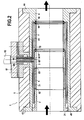
- the figures 1 and 2 present two views of a system according to one aspect of the invention.
- the system 1 as illustrated comprises an upstream mass 2, a measuring electrode 3 and a downstream mass 4 successively arranged in an insulating sheath 6 (not shown in FIG. figure 1 ), providing thermal and electrical insulation.
- the measuring electrode 3, the upstream mass 2 and the downstream mass 4 form an electrode system; the measuring electrode 3 typically forms the cathode, while the upstream mass 2 and the downstream mass 4 then form anodes.
- the measuring electrode 3 is arranged to be separated from the upstream mass 2, so that the measuring electrode 3 and the upstream mass 2 are not in direct electrical contact.
- the system thus comprises for example an insulating spacer 5, defining a minimum spacing between the measuring electrode 3 and the upstream mass 2.
- the upstream mass 2, the insulating spacer 5, the measuring electrode 3 and the downstream mass 4 each have an identical internal section, so as to define an internal conduit of constant section when they are placed end to end, for example of tubular section, cylindrical of revolution.
- the upstream mass 2 and the downstream mass 4 are made of conductive material, and form the structure of a portion of a flow pipe of a two-phase fluid. When the system is used, the upstream mass 2 and the downstream mass 4 are thus directly connected to the electrical ground of the installation, in the same way as the pipe into which the system is inserted.
- the insulating spacer 5 is disposed between the upstream mass 2 and the measuring electrode 3; the insulating spacer 5 is made of an electrically insulating material so as to isolate them electrically with respect to each other.
- the measurement electrode 3 thus makes it possible to measure the permittivity of a diphasic flowing in the internal duct thus formed by the system 1, said diphasic flowing from the upstream mass 2 to the downstream mass 4, as indicated by the arrows on the figure 2 .
- the measurements thus produced are, for example, processed by means of a conditioning unit responsible for converting the capacitance variation into a variation of an electrical quantity (voltage, current, frequency, etc.), which may notably be connected to a computer or any other suitable processing unit.
- a conditioning unit responsible for converting the capacitance variation into a variation of an electrical quantity (voltage, current, frequency, etc.), which may notably be connected to a computer or any other suitable processing unit.
- the upstream mass 2 and the downstream mass 4 are connected to the electrical ground of the installation, the sensitivity of the proposed system 1 to interference is reduced, the processing of the measurements is thus simplified compared to conventional measurement systems in which the elements forming the anode and the cathode of the system 1 are electrically isolated from the pipe.
- the proposed system uses the electrical mass of the installation as a reference of the electrical potential, unlike the prior systems for which the different electrodes are each isolated from the pipe and thus from the mass of the installation.
- the proposed system therefore makes it possible to produce a capacitive sensor, of which at least one of the electrodes (in this case the upstream and downstream masses 4, typically forming anodes) is formed by the pipe itself, and is therefore connected to the electrical ground of the installation of the pipe.
- the electrodes in this case the upstream and downstream masses 4, typically forming anodes
- the system 1 is adapted to be integrated in a two-phase circulation line, for example a propellant supply line of a spacecraft.
- the system 1 is then interposed between an upstream pipe and a downstream pipe to which it is connected for example by means of flanges or connectors.
- the internal duct defined by the system 1 then has a section identical to the section of the upstream and downstream pipes to which it is intended to be connected.
- the system 1 thus makes it possible to measure the evolution of the gas content within a two-phase flow, without generating losses in this flow.
- the various components of the system 1 are in fact configured so as to be an extension of the flow line, and not within the flow as is observed in the known systems.
- the components carrying out the measurements making it possible to measure the evolution of the gas content within a two-phase flow are not limited in terms of dimensions.
- the system 1 can therefore be adapted to pipes of any size, for example pipes having a diameter of between 4 and 60 millimeters.
- such a system 1 makes it possible to acquire data in a direct manner, without multiplexing, which considerably facilitates the exploitation of the measurements with respect to the prior systems which generate multiplexed data.
- the measured response is then little dependent on the radial position of the air bubbles in the two-phase flow.
- the system 1 also comprises a guard electrode 7, subjected to the same potential as the measuring electrode 3, in order to compensate for the electrical disturbances caused in particular by the downstream mass 4 and by other mechanical elements of the system 1 connected to the upstream mass 2 or downstream 4.
- the guard electrode 7 is then interposed between the measuring electrode 3 and the downstream mass 4, without being in contact with the electrode measuring 3 and the downstream mass 4.
- the guard electrode 7 comprises a guard sleeve 71 having a cylindrical portion extending to the upstream mass 2, between the insulating sheath 1 on the one hand, and the 3, the insulating spacer 5 and the upstream mass 2 on the other hand, without being in contact neither with the measuring electrode 3, nor with the upstream mass 2.
- the insulating spacer 5 can thus have a diameter substantially greater than that of the measuring electrode 3 and the upstream mass 2, so as to ensure a spacing between the guard electrode 7 and the measuring electrode 3 and the upstream mass 2.
- the downstream mass 4 has in turn an inner sleeve 41, extending between the insulating sheath 6 on the one hand, and the measuring electrode 3, the insulating spacer 5 the upstream mass 2 and, if necessary, the electrode on the other hand.
- the guard sleeve 71 thus isolates the measurement electrode 3 and the spacer 5 from the downstream mass 4, the guard sleeve 71 being interposed between the measurement electrode 3 and the spacer 5 on the one hand, and the inner sleeve 41 of the downstream mass 4 on the other.
- the downstream mass 4 forms a downstream end of the system 1.
- the downstream mass 4 comprises a shoulder 42 from which the inner sleeve 41 extends, and forming an abutment against which is positioned l guard electrode 7.
- the guard electrode 7 comprises a shoulder 72 from which the guard sleeve 71 extends, the shoulder 72 forming a stop against which is positioned the measuring electrode 3.
- the downstream mass 4 is initially positioned in the insulating sheath 6.
- the guard electrode 7 is then inserted via the upstream end, so that it abuts against the shoulder of the mass downstream 4.
- a sealing element 84 is typically disposed between the guard electrode 7 and the downstream body 4, so as to electrically isolate the guard electrode 7 from the downstream body 4.
- the measuring electrode 3 is then inserted via the upstream end until it abuts against the shoulder 72 of the guard electrode 71.
- a sealing element 87 is typically disposed between the guard electrode 7. and the downstream mass 4.
- the spacer 5 is then inserted via the upstream end until it abuts against the measuring electrode 3.
- the upstream mass 2 is inserted via the upstream end, until it abuts against the spacer 5.
- the spacer 5 typically comprises centering means 52 and 53, so as to center the spacer 5 respectively with respect to the upstream mass 2 and to the measuring electrode 3.
- the upstream mass 2 comprises for example a threaded portion 21, adapted to be screwed onto a threaded portion 45 of the inner sleeve 41 of the downstream mass 4, forming for example the upstream end of the system 1.
- the upstream mass 2 carries out a maintenance of the various elements of the system 1 arranged between the upstream mass 2 and the downstream mass 4, namely the insulating spacer 5, the measuring electrode 3 and the guard electrode 7 in the embodiment shown.
- the downstream mass 4 has two radial flanges at its two ends, respectively an upstream flange 43 and a downstream flange 44.
- the potentials applied to the electrodes generate an electrostatic field.
- the generated electrostatic field itself depends in particular on the dimensions of the various components and their relative positioning, dimensions and positioning. the different components of the system 1 thus affect the sensitivity of the system 1.
- the various components of the system are advantageously configured so that a maximum of field lines are located within the portion of the system 1 corresponding to the difference between the measuring electrode 3 and the upstream mass 2, that is to say the portion of the system corresponding to the insulating spacer 5 in the case where the system 1 comprises such an insulating spacer 5 between the measuring electrode 3 and the upstream mass 2.
- the measuring electrode 3 is typically arranged so as to be not far from the upstream mass 2, for example at a distance of between 10 and 20 mm in the case of a duct 29 mm in diameter, or from the order of 15mm.
- the insulating spacer 5 therefore has a dimension adapted to ensure this spacing.
- the measuring electrode 3 can be subdivided into several sectors, for example four sectors each corresponding substantially to a quarter of a circle in the case of a flow in a tubular pipe.
- the different sectors can for example be isolated from each other by portions of insulating material, The measurements made on each of the sectors then make it possible to detect in which sector the gas bubbles of the two-phase flow are located, and thus make it possible to determine the proportion of gases in the different sectors of the two-phase flow.
Landscapes
- Chemical & Material Sciences (AREA)
- Analytical Chemistry (AREA)
- Electrochemistry (AREA)
- Physics & Mathematics (AREA)
- Health & Medical Sciences (AREA)
- Life Sciences & Earth Sciences (AREA)
- Chemical Kinetics & Catalysis (AREA)
- Biochemistry (AREA)
- General Health & Medical Sciences (AREA)
- General Physics & Mathematics (AREA)
- Immunology (AREA)
- Pathology (AREA)
- Investigating Or Analyzing Materials By The Use Of Electric Means (AREA)
- Measuring Volume Flow (AREA)
Claims (4)
- Baugruppe, die eine vorgelagerte Leitung, eine nachgelagerte Leitung und ein System (1) zur Messung der Veränderung des Gasgehalts einer Zweiphasenströmung umfasst, wobei das System (1) umfasst- eine isolierende Hülle (6), die ein vorgelagertes Ende und ein nachgelagertes Ende aufweist,- eine vorgelagerte Masse (2), die mit einem leitfähigen Material umgesetzt wird, eine Messelektrode (3), eine Schutzelektrode (7) und eine nachgelagerte Masse (4), die mit einem leitfähigen Material umgesetzt wird, die nacheinander in der isolierenden Hülle (6) angeordnet sind und jeweils einen identischen inneren Abschnitt aufweisen, der eine innere Leitung einer Zweiphasenströmung von der vorgelagerten Masse (2) zu der nachgelagerten Masse (4) definiert, wobei die Schutzelektrode (7) dazu ausgestaltet ist, einem gleichen Potenzial zu unterliegen wie die Messelektrode (3), wobei die Messelektrode (3) dazu ausgestaltet ist, in Bezug auf die vorgelagerten Masse (2) die Kapazität und die Veränderung der Kapazität des Mediums zu messen, das die Zweiphasenströmung bildet,
wobei die Baugruppe dadurch gekennzeichnet ist, dass
die vorgelagerte und nachgelagerte Leitung einen inneren Abschnitt aufweisen, der mit dem inneren Abschnitt des Messsystems (1) identisch ist,
die vorgelagerte und nachgelagert Leitung fluidisch über das Messsystem (1) verbunden sind, sodass sich die innere Leitung des Messsystems in der Verlängerung der inneren Leitungen der vorgelagerten und nachgelagerten Leitung befindet,
die vorgelagerte Masse (2) und die nachgelagerte Masse (4) jeweils an der vorgelagerten Leitung und an der nachgelagerten Leitung elektrisch verbunden sind und
die Baugruppe ferner eine Behandlungseinheit umfasst, die dazu ausgestaltet ist, die Messungen der Kapazität zu behandeln, die zwischen der Messelektrode (3) und der vorgelagerten Masse (2) ausgeführt werden. - Baugruppe (1) nach Anspruch 1, die ferner einen isolierenden Abstandshalter (5), der in der isolierenden Hülle (6) zwischen der Messelektrode (3) und der vorgelagerten Masse (2) angeordnet ist, umfasst und einen inneren Abschnitt aufweist, der mit dem der Messelektrode (3) und der vorgelagerten Masse (2) identisch ist, um die vorgelagerte Masse (2) in Bezug auf die Messelektrode (3) elektrisch zu isolieren.
- Baugruppe (1) nach Anspruch 2, wobei die Schutzelektrode (7) eine Schutzummantelung (71) umfasst, die einen zylindrischen Teil umfasst, der sich bis zu der vorgelagerten Masse (2), zwischen der isolierenden Hülle (6) einerseits, und der Messelektrode (3), dem isolierenden Abstandshalter (5) und der vorgelagerten Masse (2) andererseits, erstreckt.
- Baugruppe (1) nach Anspruch 3, wobei die nachgelagerte Masse (4) eine innere Ummantelung (41) umfasst, die einen zylindrischen Teil umfasst, der sich entlang der isolierenden Hülle (6), zwischen der isolierenden Hülle (6) einerseits, und der Masselektrode (3) und der vorgelagerten Masse (2) andererseits, erstreckt.
Applications Claiming Priority (2)
| Application Number | Priority Date | Filing Date | Title |
|---|---|---|---|
| FR1460787A FR3028315B1 (fr) | 2014-11-07 | 2014-11-07 | Systeme ameliore de mesure du taux de gaz dans un ecoulement fluide |
| PCT/FR2015/052981 WO2016071635A1 (fr) | 2014-11-07 | 2015-11-04 | Ensemble de mesure capacitive du taux de gaz dans un ecoulement fluide |
Publications (2)
| Publication Number | Publication Date |
|---|---|
| EP3215835A1 EP3215835A1 (de) | 2017-09-13 |
| EP3215835B1 true EP3215835B1 (de) | 2019-08-28 |
Family
ID=52807872
Family Applications (1)
| Application Number | Title | Priority Date | Filing Date |
|---|---|---|---|
| EP15808706.4A Active EP3215835B1 (de) | 2014-11-07 | 2015-11-04 | Einheit zur kapazitiven messung des gasgehalts in einer fliessenden flussigkeit |
Country Status (4)
| Country | Link |
|---|---|
| US (1) | US10073050B2 (de) |
| EP (1) | EP3215835B1 (de) |
| FR (1) | FR3028315B1 (de) |
| WO (1) | WO2016071635A1 (de) |
Cited By (1)
| Publication number | Priority date | Publication date | Assignee | Title |
|---|---|---|---|---|
| CN109764923A (zh) * | 2018-12-27 | 2019-05-17 | 苏州化工仪表有限公司 | 一种方便安装和连接的热式气体质量流量计 |
Families Citing this family (3)
| Publication number | Priority date | Publication date | Assignee | Title |
|---|---|---|---|---|
| US11408847B2 (en) | 2017-06-13 | 2022-08-09 | Tech4Imaging Llc | Extreme-condition sensors for use with electrical capacitance volume tomography and capacitance sensing applications |
| JP7195079B2 (ja) * | 2018-07-23 | 2022-12-23 | 株式会社Ihi | トモグラフィ計測センサ及び装置 |
| US20220214293A1 (en) * | 2019-05-22 | 2022-07-07 | Transtech Systems, Inc. | In-process parallel plate sensor system for electromagnetic impedance spectroscopy monitoring of fluids |
Family Cites Families (8)
| Publication number | Priority date | Publication date | Assignee | Title |
|---|---|---|---|---|
| US3374672A (en) * | 1965-07-06 | 1968-03-26 | California Inst Res Found | Flowmeter |
| US4751842A (en) * | 1987-01-05 | 1988-06-21 | Texaco Inc. | Means and method for measuring a multi-phase distribution within a flowing petroleum stream |
| US5095758A (en) * | 1990-11-29 | 1992-03-17 | Texaco Inc. | Water cut monitoring means and method |
| IT1258181B (it) * | 1992-08-05 | 1996-02-20 | Apparecchiatura per la determinazione della frazione d'acqua in una corrente di idrocarburi luquidi anche in presenza di gas | |
| US6467358B1 (en) * | 1997-10-22 | 2002-10-22 | Japan National Oil Corp. | Method of measuring flow rates of respective fluids constituting multiphase fluid and flow meter for multiphase flow utilizing same |
| FR2780499B1 (fr) * | 1998-06-25 | 2000-08-18 | Schlumberger Services Petrol | Dispositifs de caracterisation de l'ecoulement d'un fluide polyphasique |
| AT505013B1 (de) * | 2004-02-10 | 2008-10-15 | Univ Graz Tech | Vorrichtung zur messung von fördereigenschaften in rohren |
| FR2978828B1 (fr) | 2011-08-02 | 2013-09-06 | Snecma | Capteur multi-electrode pour determiner la teneur en gaz dans un ecoulement diphasique |
-
2014
- 2014-11-07 FR FR1460787A patent/FR3028315B1/fr active Active
-
2015
- 2015-11-04 US US15/524,950 patent/US10073050B2/en active Active
- 2015-11-04 EP EP15808706.4A patent/EP3215835B1/de active Active
- 2015-11-04 WO PCT/FR2015/052981 patent/WO2016071635A1/fr active Application Filing
Non-Patent Citations (1)
| Title |
|---|
| None * |
Cited By (1)
| Publication number | Priority date | Publication date | Assignee | Title |
|---|---|---|---|---|
| CN109764923A (zh) * | 2018-12-27 | 2019-05-17 | 苏州化工仪表有限公司 | 一种方便安装和连接的热式气体质量流量计 |
Also Published As
| Publication number | Publication date |
|---|---|
| FR3028315A1 (fr) | 2016-05-13 |
| US20170350845A1 (en) | 2017-12-07 |
| EP3215835A1 (de) | 2017-09-13 |
| FR3028315B1 (fr) | 2018-06-01 |
| US10073050B2 (en) | 2018-09-11 |
| WO2016071635A1 (fr) | 2016-05-12 |
Similar Documents
| Publication | Publication Date | Title |
|---|---|---|
| EP3215835B1 (de) | Einheit zur kapazitiven messung des gasgehalts in einer fliessenden flussigkeit | |
| US9476775B2 (en) | Exhaust gas temperature sensor including strain relief and/or anti-vibration sleeve | |
| WO2011015797A1 (fr) | Capteur de pression capacitif integrant une mesure de temperature compatible avec les milieux chauds | |
| EP2064530B1 (de) | Multisensormessanordnung für füllstandsmessgerät an bord eines flugzeuges | |
| FR2896587A1 (fr) | Capteur de detection d'etat d'un liquide. | |
| EP2859312B1 (de) | Kapazitive füllstandsonde für einen flüssiggas-behälter, und einheit bestehend aus einem ventil und einer kapazitiven füllstandsonde | |
| WO2013017795A1 (fr) | Capteur multi-electrode pour determiner la teneur en gaz dans un ecoulement diphasique | |
| FR2825152A1 (fr) | Montage d'electrodes, notamment destine a etre integre dans une conduite de gaz d'echappement | |
| FR2972215A1 (fr) | Composant de garniture de forage comprenant un coupleur mobile et une chambre a pression | |
| FR2797721A1 (fr) | Bougie d'allumage equipee d'un capteur de pression, et moteur thermique equipe de telles bougies | |
| FR3056747A1 (fr) | Systeme d'essai pour mesurer une cinematique de decouplage de deux pieces boulonnees de turbomachine | |
| FR2972311A1 (fr) | Coupleur annulaire pour composant de garniture de forage | |
| EP3830391A1 (de) | Vorrichtung zur erfassung und übertragung von daten zwischen säulen von öl- oder gasbohrungen | |
| EP1897193B1 (de) | Zündkerze für einen verbrennungsmotor | |
| FR3009868A1 (fr) | Dispositif de mesure de differences de potentiels electriques pour structure metallique sous-marine equipee d'un systeme de protection cathodique, et procede associe | |
| EP3737920B1 (de) | Vorrichtung zur kapazitiven messung in einem mehrphasigen medium | |
| EP3538803B1 (de) | Verbindungskörper, verschraubungen und hydraulisches system für den durchgang einer flüssigkeit zwischen zwei hydraulischen kreisläufen, zugehöriges verfahren und montage | |
| WO2015091418A1 (fr) | Dispositif de mesure de différences de potentiels électriques pour structure métallique sous-marine équipée d'un système de protection cathodique, et procédé associé | |
| CA3026937C (fr) | Outil et procede de purge d'eau d'un reservoir de carburant | |
| BE1026619B1 (fr) | Systeme de mesure pour turbomachine | |
| FR2955215A1 (fr) | Bougie d'allumage comprenant un detecteur de pression de cylindre et un detecteur de cliquetis | |
| FR3044865A1 (fr) | Calculateur electronique d'une turbomachine d'aeronef | |
| FR2984494A1 (fr) | Capteur de temperature | |
| FR2934675A1 (fr) | Capteur capacitif. | |
| FR3078742A1 (fr) | Detection electrique du raccordement d’un dispositif de rechauffage de fluide pour un moteur thermique a combustion interne |
Legal Events
| Date | Code | Title | Description |
|---|---|---|---|
| STAA | Information on the status of an ep patent application or granted ep patent |
Free format text: STATUS: THE INTERNATIONAL PUBLICATION HAS BEEN MADE |
|
| PUAI | Public reference made under article 153(3) epc to a published international application that has entered the european phase |
Free format text: ORIGINAL CODE: 0009012 |
|
| STAA | Information on the status of an ep patent application or granted ep patent |
Free format text: STATUS: REQUEST FOR EXAMINATION WAS MADE |
|
| 17P | Request for examination filed |
Effective date: 20170607 |
|
| AK | Designated contracting states |
Kind code of ref document: A1 Designated state(s): AL AT BE BG CH CY CZ DE DK EE ES FI FR GB GR HR HU IE IS IT LI LT LU LV MC MK MT NL NO PL PT RO RS SE SI SK SM TR |
|
| AX | Request for extension of the european patent |
Extension state: BA ME |
|
| DAV | Request for validation of the european patent (deleted) | ||
| DAX | Request for extension of the european patent (deleted) | ||
| GRAP | Despatch of communication of intention to grant a patent |
Free format text: ORIGINAL CODE: EPIDOSNIGR1 |
|
| STAA | Information on the status of an ep patent application or granted ep patent |
Free format text: STATUS: GRANT OF PATENT IS INTENDED |
|
| INTG | Intention to grant announced |
Effective date: 20190227 |
|
| GRAJ | Information related to disapproval of communication of intention to grant by the applicant or resumption of examination proceedings by the epo deleted |
Free format text: ORIGINAL CODE: EPIDOSDIGR1 |
|
| STAA | Information on the status of an ep patent application or granted ep patent |
Free format text: STATUS: REQUEST FOR EXAMINATION WAS MADE |
|
| GRAR | Information related to intention to grant a patent recorded |
Free format text: ORIGINAL CODE: EPIDOSNIGR71 |
|
| GRAS | Grant fee paid |
Free format text: ORIGINAL CODE: EPIDOSNIGR3 |
|
| STAA | Information on the status of an ep patent application or granted ep patent |
Free format text: STATUS: GRANT OF PATENT IS INTENDED |
|
| GRAA | (expected) grant |
Free format text: ORIGINAL CODE: 0009210 |
|
| STAA | Information on the status of an ep patent application or granted ep patent |
Free format text: STATUS: THE PATENT HAS BEEN GRANTED |
|
| INTC | Intention to grant announced (deleted) | ||
| AK | Designated contracting states |
Kind code of ref document: B1 Designated state(s): AL AT BE BG CH CY CZ DE DK EE ES FI FR GB GR HR HU IE IS IT LI LT LU LV MC MK MT NL NO PL PT RO RS SE SI SK SM TR |
|
| INTG | Intention to grant announced |
Effective date: 20190723 |
|
| REG | Reference to a national code |
Ref country code: GB Ref legal event code: FG4D Free format text: NOT ENGLISH |
|
| REG | Reference to a national code |
Ref country code: CH Ref legal event code: EP |
|
| REG | Reference to a national code |
Ref country code: AT Ref legal event code: REF Ref document number: 1173024 Country of ref document: AT Kind code of ref document: T Effective date: 20190915 |
|
| REG | Reference to a national code |
Ref country code: IE Ref legal event code: FG4D Free format text: LANGUAGE OF EP DOCUMENT: FRENCH |
|
| REG | Reference to a national code |
Ref country code: DE Ref legal event code: R096 Ref document number: 602015036847 Country of ref document: DE |
|
| REG | Reference to a national code |
Ref country code: NL Ref legal event code: MP Effective date: 20190828 |
|
| REG | Reference to a national code |
Ref country code: LT Ref legal event code: MG4D |
|
| PG25 | Lapsed in a contracting state [announced via postgrant information from national office to epo] |
Ref country code: SE Free format text: LAPSE BECAUSE OF FAILURE TO SUBMIT A TRANSLATION OF THE DESCRIPTION OR TO PAY THE FEE WITHIN THE PRESCRIBED TIME-LIMIT Effective date: 20190828 Ref country code: HR Free format text: LAPSE BECAUSE OF FAILURE TO SUBMIT A TRANSLATION OF THE DESCRIPTION OR TO PAY THE FEE WITHIN THE PRESCRIBED TIME-LIMIT Effective date: 20190828 Ref country code: PT Free format text: LAPSE BECAUSE OF FAILURE TO SUBMIT A TRANSLATION OF THE DESCRIPTION OR TO PAY THE FEE WITHIN THE PRESCRIBED TIME-LIMIT Effective date: 20191230 Ref country code: FI Free format text: LAPSE BECAUSE OF FAILURE TO SUBMIT A TRANSLATION OF THE DESCRIPTION OR TO PAY THE FEE WITHIN THE PRESCRIBED TIME-LIMIT Effective date: 20190828 Ref country code: LT Free format text: LAPSE BECAUSE OF FAILURE TO SUBMIT A TRANSLATION OF THE DESCRIPTION OR TO PAY THE FEE WITHIN THE PRESCRIBED TIME-LIMIT Effective date: 20190828 Ref country code: NO Free format text: LAPSE BECAUSE OF FAILURE TO SUBMIT A TRANSLATION OF THE DESCRIPTION OR TO PAY THE FEE WITHIN THE PRESCRIBED TIME-LIMIT Effective date: 20191128 Ref country code: BG Free format text: LAPSE BECAUSE OF FAILURE TO SUBMIT A TRANSLATION OF THE DESCRIPTION OR TO PAY THE FEE WITHIN THE PRESCRIBED TIME-LIMIT Effective date: 20191128 Ref country code: NL Free format text: LAPSE BECAUSE OF FAILURE TO SUBMIT A TRANSLATION OF THE DESCRIPTION OR TO PAY THE FEE WITHIN THE PRESCRIBED TIME-LIMIT Effective date: 20190828 |
|
| PG25 | Lapsed in a contracting state [announced via postgrant information from national office to epo] |
Ref country code: AL Free format text: LAPSE BECAUSE OF FAILURE TO SUBMIT A TRANSLATION OF THE DESCRIPTION OR TO PAY THE FEE WITHIN THE PRESCRIBED TIME-LIMIT Effective date: 20190828 Ref country code: ES Free format text: LAPSE BECAUSE OF FAILURE TO SUBMIT A TRANSLATION OF THE DESCRIPTION OR TO PAY THE FEE WITHIN THE PRESCRIBED TIME-LIMIT Effective date: 20190828 Ref country code: LV Free format text: LAPSE BECAUSE OF FAILURE TO SUBMIT A TRANSLATION OF THE DESCRIPTION OR TO PAY THE FEE WITHIN THE PRESCRIBED TIME-LIMIT Effective date: 20190828 Ref country code: GR Free format text: LAPSE BECAUSE OF FAILURE TO SUBMIT A TRANSLATION OF THE DESCRIPTION OR TO PAY THE FEE WITHIN THE PRESCRIBED TIME-LIMIT Effective date: 20191129 Ref country code: RS Free format text: LAPSE BECAUSE OF FAILURE TO SUBMIT A TRANSLATION OF THE DESCRIPTION OR TO PAY THE FEE WITHIN THE PRESCRIBED TIME-LIMIT Effective date: 20190828 Ref country code: IS Free format text: LAPSE BECAUSE OF FAILURE TO SUBMIT A TRANSLATION OF THE DESCRIPTION OR TO PAY THE FEE WITHIN THE PRESCRIBED TIME-LIMIT Effective date: 20191228 |
|
| REG | Reference to a national code |
Ref country code: CH Ref legal event code: NV Representative=s name: VALIPAT S.A. C/O BOVARD SA NEUCHATEL, CH |
|
| RAP2 | Party data changed (patent owner data changed or rights of a patent transferred) |
Owner name: SAFRAN AIRCRAFT ENGINES |
|
| REG | Reference to a national code |
Ref country code: AT Ref legal event code: MK05 Ref document number: 1173024 Country of ref document: AT Kind code of ref document: T Effective date: 20190828 |
|
| PG25 | Lapsed in a contracting state [announced via postgrant information from national office to epo] |
Ref country code: TR Free format text: LAPSE BECAUSE OF FAILURE TO SUBMIT A TRANSLATION OF THE DESCRIPTION OR TO PAY THE FEE WITHIN THE PRESCRIBED TIME-LIMIT Effective date: 20190828 |
|
| PG25 | Lapsed in a contracting state [announced via postgrant information from national office to epo] |
Ref country code: RO Free format text: LAPSE BECAUSE OF FAILURE TO SUBMIT A TRANSLATION OF THE DESCRIPTION OR TO PAY THE FEE WITHIN THE PRESCRIBED TIME-LIMIT Effective date: 20190828 Ref country code: DK Free format text: LAPSE BECAUSE OF FAILURE TO SUBMIT A TRANSLATION OF THE DESCRIPTION OR TO PAY THE FEE WITHIN THE PRESCRIBED TIME-LIMIT Effective date: 20190828 Ref country code: EE Free format text: LAPSE BECAUSE OF FAILURE TO SUBMIT A TRANSLATION OF THE DESCRIPTION OR TO PAY THE FEE WITHIN THE PRESCRIBED TIME-LIMIT Effective date: 20190828 Ref country code: PL Free format text: LAPSE BECAUSE OF FAILURE TO SUBMIT A TRANSLATION OF THE DESCRIPTION OR TO PAY THE FEE WITHIN THE PRESCRIBED TIME-LIMIT Effective date: 20190828 Ref country code: AT Free format text: LAPSE BECAUSE OF FAILURE TO SUBMIT A TRANSLATION OF THE DESCRIPTION OR TO PAY THE FEE WITHIN THE PRESCRIBED TIME-LIMIT Effective date: 20190828 |
|
| PG25 | Lapsed in a contracting state [announced via postgrant information from national office to epo] |
Ref country code: CZ Free format text: LAPSE BECAUSE OF FAILURE TO SUBMIT A TRANSLATION OF THE DESCRIPTION OR TO PAY THE FEE WITHIN THE PRESCRIBED TIME-LIMIT Effective date: 20190828 Ref country code: IS Free format text: LAPSE BECAUSE OF FAILURE TO SUBMIT A TRANSLATION OF THE DESCRIPTION OR TO PAY THE FEE WITHIN THE PRESCRIBED TIME-LIMIT Effective date: 20200224 Ref country code: SM Free format text: LAPSE BECAUSE OF FAILURE TO SUBMIT A TRANSLATION OF THE DESCRIPTION OR TO PAY THE FEE WITHIN THE PRESCRIBED TIME-LIMIT Effective date: 20190828 Ref country code: SK Free format text: LAPSE BECAUSE OF FAILURE TO SUBMIT A TRANSLATION OF THE DESCRIPTION OR TO PAY THE FEE WITHIN THE PRESCRIBED TIME-LIMIT Effective date: 20190828 |
|
| REG | Reference to a national code |
Ref country code: DE Ref legal event code: R097 Ref document number: 602015036847 Country of ref document: DE |
|
| PLBE | No opposition filed within time limit |
Free format text: ORIGINAL CODE: 0009261 |
|
| STAA | Information on the status of an ep patent application or granted ep patent |
Free format text: STATUS: NO OPPOSITION FILED WITHIN TIME LIMIT |
|
| PG2D | Information on lapse in contracting state deleted |
Ref country code: IS |
|
| PG25 | Lapsed in a contracting state [announced via postgrant information from national office to epo] |
Ref country code: LU Free format text: LAPSE BECAUSE OF NON-PAYMENT OF DUE FEES Effective date: 20191104 Ref country code: MC Free format text: LAPSE BECAUSE OF FAILURE TO SUBMIT A TRANSLATION OF THE DESCRIPTION OR TO PAY THE FEE WITHIN THE PRESCRIBED TIME-LIMIT Effective date: 20190828 |
|
| 26N | No opposition filed |
Effective date: 20200603 |
|
| REG | Reference to a national code |
Ref country code: BE Ref legal event code: MM Effective date: 20191130 |
|
| PG25 | Lapsed in a contracting state [announced via postgrant information from national office to epo] |
Ref country code: SI Free format text: LAPSE BECAUSE OF FAILURE TO SUBMIT A TRANSLATION OF THE DESCRIPTION OR TO PAY THE FEE WITHIN THE PRESCRIBED TIME-LIMIT Effective date: 20190828 |
|
| GBPC | Gb: european patent ceased through non-payment of renewal fee |
Effective date: 20191128 |
|
| PG25 | Lapsed in a contracting state [announced via postgrant information from national office to epo] |
Ref country code: GB Free format text: LAPSE BECAUSE OF NON-PAYMENT OF DUE FEES Effective date: 20191128 Ref country code: IE Free format text: LAPSE BECAUSE OF NON-PAYMENT OF DUE FEES Effective date: 20191104 |
|
| PG25 | Lapsed in a contracting state [announced via postgrant information from national office to epo] |
Ref country code: BE Free format text: LAPSE BECAUSE OF NON-PAYMENT OF DUE FEES Effective date: 20191130 |
|
| PG25 | Lapsed in a contracting state [announced via postgrant information from national office to epo] |
Ref country code: CY Free format text: LAPSE BECAUSE OF FAILURE TO SUBMIT A TRANSLATION OF THE DESCRIPTION OR TO PAY THE FEE WITHIN THE PRESCRIBED TIME-LIMIT Effective date: 20190828 |
|
| PG25 | Lapsed in a contracting state [announced via postgrant information from national office to epo] |
Ref country code: MT Free format text: LAPSE BECAUSE OF FAILURE TO SUBMIT A TRANSLATION OF THE DESCRIPTION OR TO PAY THE FEE WITHIN THE PRESCRIBED TIME-LIMIT Effective date: 20190828 Ref country code: HU Free format text: LAPSE BECAUSE OF FAILURE TO SUBMIT A TRANSLATION OF THE DESCRIPTION OR TO PAY THE FEE WITHIN THE PRESCRIBED TIME-LIMIT; INVALID AB INITIO Effective date: 20151104 |
|
| PG25 | Lapsed in a contracting state [announced via postgrant information from national office to epo] |
Ref country code: MK Free format text: LAPSE BECAUSE OF FAILURE TO SUBMIT A TRANSLATION OF THE DESCRIPTION OR TO PAY THE FEE WITHIN THE PRESCRIBED TIME-LIMIT Effective date: 20190828 |
|
| PGFP | Annual fee paid to national office [announced via postgrant information from national office to epo] |
Ref country code: IT Payment date: 20231019 Year of fee payment: 9 Ref country code: FR Payment date: 20231019 Year of fee payment: 9 Ref country code: DE Payment date: 20231019 Year of fee payment: 9 Ref country code: CH Payment date: 20231201 Year of fee payment: 9 |