EP3215220B1 - Création d'un plan de traitement robuste de radiothérapie - Google Patents
Création d'un plan de traitement robuste de radiothérapie Download PDFInfo
- Publication number
- EP3215220B1 EP3215220B1 EP14827175.2A EP14827175A EP3215220B1 EP 3215220 B1 EP3215220 B1 EP 3215220B1 EP 14827175 A EP14827175 A EP 14827175A EP 3215220 B1 EP3215220 B1 EP 3215220B1
- Authority
- EP
- European Patent Office
- Prior art keywords
- scenarios
- scenario
- region
- mappings
- interest
- Prior art date
- Legal status (The legal status is an assumption and is not a legal conclusion. Google has not performed a legal analysis and makes no representation as to the accuracy of the status listed.)
- Not-in-force
Links
- 238000011282 treatment Methods 0.000 title claims description 74
- 238000001959 radiotherapy Methods 0.000 title claims description 20
- 238000013507 mapping Methods 0.000 claims description 62
- 238000009826 distribution Methods 0.000 claims description 50
- 230000006870 function Effects 0.000 claims description 46
- 238000000034 method Methods 0.000 claims description 42
- 238000005457 optimization Methods 0.000 claims description 38
- 238000004590 computer program Methods 0.000 claims description 9
- 230000005855 radiation Effects 0.000 claims description 8
- 238000011156 evaluation Methods 0.000 claims description 7
- 230000003068 static effect Effects 0.000 description 15
- 210000000056 organ Anatomy 0.000 description 8
- 238000013459 approach Methods 0.000 description 7
- 230000000694 effects Effects 0.000 description 7
- 230000001419 dependent effect Effects 0.000 description 6
- 206010028980 Neoplasm Diseases 0.000 description 5
- 238000002591 computed tomography Methods 0.000 description 4
- 150000002500 ions Chemical class 0.000 description 4
- 231100000628 reference dose Toxicity 0.000 description 4
- 238000004458 analytical method Methods 0.000 description 3
- 238000006243 chemical reaction Methods 0.000 description 3
- 210000001519 tissue Anatomy 0.000 description 3
- 238000013519 translation Methods 0.000 description 3
- 230000014616 translation Effects 0.000 description 3
- 230000008859 change Effects 0.000 description 2
- 239000011159 matrix material Substances 0.000 description 2
- 230000003287 optical effect Effects 0.000 description 2
- 210000000920 organ at risk Anatomy 0.000 description 2
- 238000012545 processing Methods 0.000 description 2
- 239000007787 solid Substances 0.000 description 2
- 238000011277 treatment modality Methods 0.000 description 2
- 210000001835 viscera Anatomy 0.000 description 2
- 241000710177 Citrus tristeza virus Species 0.000 description 1
- 206010060862 Prostate cancer Diseases 0.000 description 1
- 208000000236 Prostatic Neoplasms Diseases 0.000 description 1
- 210000003484 anatomy Anatomy 0.000 description 1
- 230000008901 benefit Effects 0.000 description 1
- 238000003339 best practice Methods 0.000 description 1
- 201000011510 cancer Diseases 0.000 description 1
- 238000012512 characterization method Methods 0.000 description 1
- 239000000470 constituent Substances 0.000 description 1
- 230000002349 favourable effect Effects 0.000 description 1
- 230000006872 improvement Effects 0.000 description 1
- 230000003993 interaction Effects 0.000 description 1
- 238000002665 ion therapy Methods 0.000 description 1
- 208000020816 lung neoplasm Diseases 0.000 description 1
- 208000037841 lung tumor Diseases 0.000 description 1
- 230000007246 mechanism Effects 0.000 description 1
- 230000001404 mediated effect Effects 0.000 description 1
- 238000012986 modification Methods 0.000 description 1
- 230000004048 modification Effects 0.000 description 1
- 239000002245 particle Substances 0.000 description 1
- 230000008569 process Effects 0.000 description 1
- 238000011002 quantification Methods 0.000 description 1
- 230000029058 respiratory gaseous exchange Effects 0.000 description 1
- 230000011218 segmentation Effects 0.000 description 1
- 238000002922 simulated annealing Methods 0.000 description 1
- 210000004872 soft tissue Anatomy 0.000 description 1
- 239000013598 vector Substances 0.000 description 1
Images


Classifications
-
- A—HUMAN NECESSITIES
- A61—MEDICAL OR VETERINARY SCIENCE; HYGIENE
- A61N—ELECTROTHERAPY; MAGNETOTHERAPY; RADIATION THERAPY; ULTRASOUND THERAPY
- A61N5/00—Radiation therapy
- A61N5/10—X-ray therapy; Gamma-ray therapy; Particle-irradiation therapy
- A61N5/103—Treatment planning systems
- A61N5/1037—Treatment planning systems taking into account the movement of the target, e.g. 4D-image based planning
-
- A—HUMAN NECESSITIES
- A61—MEDICAL OR VETERINARY SCIENCE; HYGIENE
- A61N—ELECTROTHERAPY; MAGNETOTHERAPY; RADIATION THERAPY; ULTRASOUND THERAPY
- A61N5/00—Radiation therapy
- A61N5/10—X-ray therapy; Gamma-ray therapy; Particle-irradiation therapy
- A61N5/103—Treatment planning systems
-
- A—HUMAN NECESSITIES
- A61—MEDICAL OR VETERINARY SCIENCE; HYGIENE
- A61N—ELECTROTHERAPY; MAGNETOTHERAPY; RADIATION THERAPY; ULTRASOUND THERAPY
- A61N5/00—Radiation therapy
- A61N5/10—X-ray therapy; Gamma-ray therapy; Particle-irradiation therapy
- A61N5/1077—Beam delivery systems
Definitions
- the present invention relates to the field of radiotherapy, and in particular to radiotherapy treatment planning yielding robust treatment plans.
- a treatment plan defining treatment parameters, such as treatment machine settings, to be used in a radiotherapy treatment session, is usually determined with the aid of a computer-based treatment planning system (TPS).
- TPS computer-based treatment planning system
- inverse treatment planning an optimization algorithm is employed for finding a set of treatment parameters that will generate an acceptable dose distribution within the patient, preferably satisfying all the clinical goals defined by the clinician.
- Radiotherapy treatment planning is based on medical images, such as three-dimensional CT images. In order to serve as basis for treatment planning, these images must be segmented. Segmentation of an image refers to the process of defining or reconstructing different internal structures or other regions of interest (ROIs) in an image. In the field of radiotherapy, these structures could for example be specific internal organs, or target volumes (such as tumors), which are identifiable in the images.
- ROIs regions of interest
- any radiotherapy treatment plan regardless of the method used to produce the plan, should be robust, meaning that the plan should efficiently take any uncertainties into consideration.
- Sources of uncertainty include for example uncertainty in the position of the target relative to the beams, uncertainty regarding the location of cancer cells, and uncertainty in the patient density data.
- a robust treatment plan must be insensitive to any errors occurring due to such uncertainties.
- a margin applied to a Clinical Target Volume defines the Planning Target Volume (PTV).
- the PTV Planning Target Volume
- margins Treatment planning using margins is usually considered to be adequate in the field of conventional photon-based radiotherapy within regions of relatively homogeneous density. This is because the "static dose cloud approximation" can be considered to be valid, meaning that a deformation of the patient anatomy has negligible impact on the dose distribution in space. Hence, the patient can be assumed to be moving within a static dose distribution, such that, for example, the effect of a patient setup error corresponds to a rigid translation of the dose distribution.
- the static dose cloud approximation is usually not valid in regions of less homogeneous density, and is usually not suitable for particle radiotherapy, for example using protons or other ions, since the Bragg peak positions (and thus the resulting dose distribution) are highly dependent on the densities of the traversed tissues. The effectiveness of margin-based treatment planning in these situations might therefore be questioned. Nonetheless, the use of margins is still heavily relied upon.
- WO2006130771 relates to a treatment planning method for four-dimensional volumes of interest where organs change shape and/or position over time, and whereby the planning system needs to take these changes into account. It specifically solves the problem of tumors moving and/or deforming during treatment and soft tissue targets moving with patient breathing during delivery.
- An aim of the present invention is to overcome, or at least mitigate, the drawbacks described above, and in particular to provide a treatment planning system that will enable robust treatment plans to be generated for a plurality of different clinical cases and different treatment modalities.
- a method for generating a robust radiotherapy treatment plan for a subject at least partly on the basis of a region of interest in the subject comprises the steps of:
- a computer program product comprises computer-readable instructions which, when executed on a computer, will cause the computer to perform a method for generating a robust radiotherapy treatment plan for a subject at least partly on the basis of a region of interest in said subject, the method comprising the steps of:
- a computer system comprising a processor coupled to a memory having stored thereon computer-readable instructions that, when executed by said processor, cause the processor to perform a method for generating a robust radiotherapy treatment plan for a subject at least partly on the basis of a region of interest in said subject, the method comprising the steps of:
- An advantage of using weights based on an overlap of scenario-specific mappings of the ROI when optimizing a treatment plan in accordance with the present invention is that robust treatment plans of high quality can be achieved for a large number of different clinical cases.
- the first and second mappings are determined as functions of dose distributions and/or density distributions corresponding to said first and second scenarios, respectively.
- weights would be determined on the basis of the actual dose- or density distributions corresponding to the different scenarios.
- the method would result in a treatment plan closely corresponding to a plan determined using conventional margin-based treatment planning, where the union of all mapped versions of the region of interest (e.g. the CTV) would essentially correspond to a region expanded by an appropriately selected margin (e.g. the PTV).
- the method would automatically result in a robust treatment plan based on the actual dose- or density distributions according to the different scenarios.
- the step of determining the overlap of the mappings of the region of interest comprises identifying the number of scenarios under which a sub-region in a scenario is located within a corresponding mapping of said region of interest. Such analysis is preferably conducted for a plurality of sub-regions. Thereby, a computationally efficient quantification of the overlap is obtained, which is readily applicable for specifying the weights used in the optimization. Using weights based on the reciprocal of the number of scenarios thus identified would ensure that sub-regions at the border of a CTV in extreme scenarios would be given an increased weight, thereby favoring plans which have a steep dose falloff at the border of the treated target region.
- a calculated weight is specific for a particular beam, or sub-beam, of radiation.
- beams or sub-beams
- errors which affect different beam doses differently are taken into account in an appropriate way.
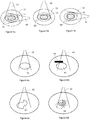
- the figures 2, 3 , 4a-c , 5a-d and 6a-c show two-dimensional cross sections of an internal image of a subject (such as a human patient), e.g. representations of single slices of a CT scan.
- a subject such as a human patient
- an image used for treatment planning usually comprises many slices defining a three-dimensional representation of the subject.
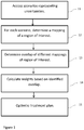
- FIG. 1 being a flow-chart indicating the steps of a method according to the invention
- figures 2 and 3 schematically illustrating the application of the method in an example of a simplified case for which the static dose cloud approximation is considered to be valid.
- scenarios representing uncertainties are accessed, e.g., from a memory of a computer.
- Scenarios could be defined manually by a user, or automatically on the basis of some input regarding estimated uncertainties.
- scenarios could be defined automatically without the need of any user interaction, for example by comparing patient or image specific data with reference cases comprising pre-defined scenarios indicating best practice for different situations.
- the present disclosure is not limited to any specific mechanisms for defining the scenarios or for estimating uncertainties. Nor is the disclosure limited to some specific kind of uncertainty, but is readily applicable in relation to any kind of uncertainty relevant for treatment planning, including range uncertainties, patient setup uncertainties and organ motion and deformation.
- step 12 a mapping of a region of interest is determined, for each scenario, as a function of the scenario.
- FIG. 2 illustrates a patient image 21 with a clinical target volume (CTV) 22 defined therein indicated by a solid ellipse, and a set of eight additional scenarios 23 that represent movement of the CTV indicated by dashed ellipses.
- CTV clinical target volume
- FIG. 2 illustrates a patient image 21 with a clinical target volume (CTV) 22 defined therein indicated by a solid ellipse, and a set of eight additional scenarios 23 that represent movement of the CTV indicated by dashed ellipses.
- CTV clinical target volume
- step 13 an overlap of different scenario-dependent mappings of the region of interest is identified.
- "Overlap” as used herein relates to the extent or degree of, or the non-existence of, a geometrical intersection between different regions.
- One exemplary way to quantify such overlap could be to identify the number of scenarios under which a specific sub-region is located within a corresponding mapping of the region of interest.
- Such analysis is made for a plurality of sub-regions of the image.
- Another exemplary way to quantify such overlap is to quantify the intensities of the different regions that are intersected.
- a medical image used for treatment planning is usually discretized into a number of volume elements, or "voxels". Hence, sub-regions could for example correspond to voxels in the image.
- the step 13 is further illustrated with reference to figure 3 .
- Figure 3 shows a situation where the conditions are similar to those described previously with reference to figure 2 , i.e. wherein a static dose cloud approximation is valid and where mappings of a CTV 32 as a function of the scenarios simply correspond to rigid translations (i.e. shifts) of the CTV within the patient image 31.
- the first shift scenario is defined by a shift in a first direction and is represented by a dotted ellipse 33.
- the second shift scenario is defined by a shift in a direction perpendicular to the first direction, and is represented by a dashed ellipse 34.
- the number of scenarios in which the voxel is located within the correspondingly mapped CTV is ascertained.
- the voxel 35 is located within the CTV of the nominal scenario and in the mapped CTVs of both the additional shift scenarios.
- the voxel 36 is located within the CTV of the nominal scenario and in the mapped CTV of the second shift scenario represented by the ellipse 34.
- the voxel 37 is only located within the mapped CTV according to the first shift scenario represented by the ellipse 33.
- weights are determined on the basis of identified overlaps.
- the weight for each sub-region in a scenario is determined on the basis of the number of identified scenarios under which a specific sub-region is located within a correspondingly mapped region of interest.
- the dose d i is a function of the treatment parameters which are to be determined by the optimization
- the reference dose d ref is the dose objective relating to a desired dose in the ROI.
- the effect of a setup error is that the patient is shifted rigidly inside a static dose distribution.
- a rigid shift of the patient corresponds to the voxel indices being shifted by a fixed offset (assuming that the shift lines up with the dose grid).
- S be the set of scenarios and let the offset corresponding to the shift of scenario s in S be denoted by j(s).
- a voxel- and scenario-specific weight (3) is proportional to the reciprocal of the number of scenarios under which the voxel is located within the corresponding rigidly shifted CTV.
- This identified number of scenarios for the different voxels in different scenarios represents the overlap of the plurality of mappings of the region of interest (i.e. the plurality of rigid shifts of the CTV according to this example).
- the penalty (2) is derived under the assumption that a static dose cloud approximation is valid.
- d(s) the real dose distribution of scenario s
- d ⁇ ( s ) the real dose distribution of scenario s
- a more universally applicable penalty function would be obtained: ⁇ s ⁇ S ⁇ i ⁇ C p i , s ⁇ d i s ,
- a treatment plan is generated.
- This step comprises optimization of an optimization function (e.g. the sum of ⁇ over the voxels) evaluated over the set of defined scenarios, wherein the evaluation comprises the use of weights as calculated in accordance with the above.
- an objective function usually a sum of different optimization functions regarding various treatment objectives relating to different regions of interest
- an optimization function based on the penalty (4) can be optimized.
- various different techniques may be employed. For example, gradient-based methods, such as methods based on sequential quadratic programming algorithms, or heuristic methods, such as simulated annealing, can be used.
- the optimization might be fluence-based, which requires subsequent conversion to machine parameters, or based on Direct Machine Parameter Optimization (DMPO) where machine parameters are directly optimized, or a combination of both.
- DMPO Direct Machine Parameter Optimization
- the optimization might comprise optimizing spot weights. Optimization of an objective function is well-known in the art of radiotherapy treatment planning and will therefore not be described in further detail herein. The present disclosure is not limited to any specific technique for optimization.
- FIG 4a-c further illustrating the effect of using an optimization function based on the penalty (4) when planning treatments for regions of heterogeneous density, or in other situations where the dose distribution will change substantially due to uncertainties.
- a dose distribution of a scenario might be deformed as a result of patient setup errors, range errors (e.g. due to errors in the image CT-to-density conversion), deformations of internal organs, etc.
- Figure 4a illustrates a CTV 41 and a dose distribution 42 determined on the basis of the nominal scenario, i.e. without any errors.
- Figure 4b illustrates the resulting dose distribution 42' as it would appear in a different scenario, for example defined by some specified deformation or motion of organs in the vicinity of the CTV.
- the dose distribution 42' has been significantly deformed, and a rigid shift of the CTV 41 within the dose distribution would not be an appropriate representation of the scenario.
- deformed dose distribution could instead be interpreted as a deformed CTV 41' in the dose distribution 42 of the nominal scenario, as would be apparent to a person skilled in the art.
- FIG 4c a deformed CTV 41', transformed in accordance with the scenario dose distribution 42', is illustrated in relation to the nominal dose distribution 42. Note that this drawing is merely for illustrative purposes and is not necessarily a realistic representation of a CTV deformed in accordance with the deformed dose distribution 42'.
- a mapping of the region of interest can be defined directly as a function of a density distribution.
- a deformed dose distribution 42' is an effect of a modified density distribution
- a deformed CTV 41' could be determined directly as a function of the modified density distribution instead of as a function of a dose distribution.
- weights are not only dependent on the overlap of scenario-specific mappings of a ROI, but are also beam dependent.
- the rationale for this is that errors might affect different beam doses differently. If, e.g., a setup shift occurs that is parallel to the incidence direction of a given beam, this will only affect the dose distribution marginally (by scaling according to the inverse square law). On the other hand, if the shift is perpendicular to the beam direction, the effect is often large. To take this into account, the beams could be considered independently.
- beam-specific weights p i , s b for the beams b in the set B of all beams could be defined.
- weights p i , s b can be stated as (3), but with j ( b ) substituted for j .
- j ( b ) ( s ) is the offset in the dose grid corresponding to the shift of scenario s projected onto the beam plane (recall that j ( s ) was defined in the same way but without the projection onto the beam plane).
- j ( b ) ( s ) neglects setup errors parallel to the direction of the beam.
- the voxel weights of different beams can be combined into a single weight, e.g., by interpolation.
- Figure 5a-c illustrates how beam-specific weights can be determined in accordance with the above.
- Figure 5a shows a CTV 51 and a first beam 53 and a second beam 54 for treating the CTV 51.
- a margin 52 indicates the PTV which would have been used for conventional margin-based planning.
- a set of five scenarios 55 is shown with dashed lines.
- Figure 5b shows the scenario mappings (i.e. shifts) of the CTV 51 projected onto the beam plane for the first beam 53, resulting in a set of mappings 56' of the CTV which are specific for the first beam 53.
- figure 5c shows the scenario mappings of the CTV 51 projected onto the beam plane for the second beam 54, resulting in a set of mappings 56" of the CTV which are specific for the second beam 54.
- multiple CTV mappings (one for each beam) for each scenario will be determined.
- the number of scenarios under which the voxel is located within a correspondingly mapped and projected CTV is determined and used as basis for calculating the voxel-, scenario- and beam-specific weight (e.g. as the reciprocal of the number of identified scenarios).
- the offset j ( b ) ( s ) could be separated into a lateral part and a longitudinal part (in the beam plane). The lateral part would be defined by the setup error projected onto the beam plane, and the longitudinal part would be defined by the range error.
- the offset for voxel i could be defined as j i ( b ) ( s ), i.e., not only dependent on the beam and scenario, but also on the voxel index.
- each constituent, or "sub-beam" of the beam dose distribution can be considered as an independent beam.
- a sub-beam can refer to a beamlet dose distribution for photon-based treatment, and to a spot dose distribution for scanned ion therapy.
- this yields an expression for the penalty to voxel i that is on the form of the penalty (5), but with B representing the set of all sub-beams and d i b s being the dose to voxel i from sub-beam b in scenario s.
- the sub-beam specific approach can be advantageous if there are large differences regarding how the different sub-beam dose distributions become deformed under different realizations of uncertainty.
- the scenarios are not only rigid setup errors or uniform range errors, e.g. if a scenario is based on non-uniform range errors or organ motion, a more general approach could be taken when considering beam-specific weights.
- a generalization of the beam-specific weights defined above is achieved when each scenario is considered to be an independent image of the patient. The patient geometry can thus deform without restriction between scenarios.
- the position of the CTV projected onto the beam plane is combined with the radiological depth of each voxel within the CTV from the direction of the considered beam.
- FIG. 6a shows a first scenario wherein treatment of a CTV 61 in a first position is planned using radiation beam 62.
- the CTV 61 has moved laterally to a second position, and a high-density region 63 has partly moved into the radiation beam path, affecting the radiological depth of a part of the CTV.
- a mapping 61' of the ROI, determined as a function of the second scenario, is shown in figure 6c .
- the resulting mapped ROI 61' is not only shifted, but also partly deformed due to the altered radiological depth caused by the high-density region 63.
- Figure 6d illustrates the overlap 64 of the ROI 61 in the first scenario and the ROI 61' mapped from the second scenario. Based on the overlap 64, the weights employed in the treatment plan optimization can be calculated as described elsewhere herein.
- D ( s ) the dose-influence matrix for scenario s such that the element D ib ( s ) at row i and column b is the dose to voxel i in scenario s from sub-beam b at unit weight.
- a ( b ) ( s , t ) a deformation matrix for sub-beam b and the pair of scenarios ( s,t ) from S such that the element A ij b s t is the fraction of the dose contribution to voxel i in scenario s from unit irradiation with sub-beam b that becomes displaced to voxel j in scenario t .
- the weight p i , s b is thus defined on the basis of the overlap between the CTV and the voxel dose contributions of sub-beam b that correspond to each other over the scenarios.
- the dose contribution i of beam b is taken as the region of interest and A ( b ) ( s , t ) defines the mapping of the region of interest between scenarios s and t .
- a discrete set of scenarios has been considered.
- an infinite set of scenarios e.g. a continuous set of scenarios
- the overlap of scenario-specific mappings would not correspond to a number of scenarios under which a voxel is located within corresponding mappings of the ROI, but rather to a probability that a voxel (or any other spatial sub-region considered) is within the ROI.
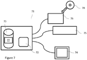
- FIG. 7 schematically illustrates an example of a computer system 71 according to the invention.
- the system comprises a processor 72, coupled to a memory 73.
- the system can include a display device 74 (e.g. for displaying patient images and dose distributions, a graphical user interface, and any other information related to treatment planning), a data input device 75 (e.g. a keyboard, a mouse or any other suitable device for data input) and a data reading/writing device 76 (e.g. an optical drive, USB interface, or any other suitable device for reading/writing data).
- the processor 72 can be of any kind, such as one or more central processing units (CPU) or any kind of parallel processor system, e.g. based on one or more graphics processing units (GPU).
- CPU central processing units
- GPU graphics processing units
- the memory 73 can be any kind of volatile or non-volatile memory suitable for storing and retrieving information, such as, for example, any kind of random access memory (RAM) or hard disk drive.
- the memory 73 has a computer program 77 stored thereon.
- the memory 73 can also have additional data stored thereon, such as, for example, information regarding various scenarios used for treatment planning, defined on the basis of an uncertainty of one or more parameters.
- the computer program 77 comprises computer-readable instructions for generating the robust radiotherapy treatment plan, where the computer-readable instructions can be transferred to, and executed by, the processor 72.
- the computer-readable instructions When executed by the processor 72, the computer-readable instructions will cause the method for generating a robust treatment plan to be performed, the method comprising optimization of a function evaluated over a set of scenarios employing weights determined on the basis of identified overlap of different scenario-specific mappings of a ROI.
- a thereby generated treatment plan can be stored on the memory 73.
- the computer program 77 can also be stored on a non-transitory computer readable medium 78, e.g. a USB drive, an optical data carrier such as a CD-ROM, or any other suitable portable information storage device, so that the computer program 77 can be loaded to the memory 73 and/or transferred to different computing systems.
- the system described with reference to figure 7 is merely an example, and a computer system according to the invention does not necessarily comprise all the illustrated components, and/or might comprise other components not illustrated.
- the method can be applied in view of any type of errors, such as organ motion or deformation or ion range errors.
- the method can be readily applied to multiple organs, including organs at risk (OARs).
- OARs organs at risk
Landscapes
- Health & Medical Sciences (AREA)
- Engineering & Computer Science (AREA)
- Biomedical Technology (AREA)
- Pathology (AREA)
- Nuclear Medicine, Radiotherapy & Molecular Imaging (AREA)
- Radiology & Medical Imaging (AREA)
- Life Sciences & Earth Sciences (AREA)
- Animal Behavior & Ethology (AREA)
- General Health & Medical Sciences (AREA)
- Public Health (AREA)
- Veterinary Medicine (AREA)
- Radiation-Therapy Devices (AREA)
Claims (9)
- Procédé de création d'un plan de traitement robuste de radiothérapie pour un sujet au moins partiellement sur la base d'une région d'intérêt dans ledit sujet, le procédé comprenant les étapes consistant à :- accéder à un ensemble de scénarios comprenant au moins un premier scénario et un deuxième scénario (11), chaque scénario de l'ensemble de scénarios représentant une concrétisation spécifique de l'incertitude d'un ou de plusieurs paramètres pertinents pour la planification du traitement ;- déterminer deux cartographies ou plus de ladite région d'intérêt (12), les deux cartographies ou plus comprenant au moins une première cartographie basée sur ledit premier scénario et une deuxième cartographie basée sur ledit deuxième scénario ;- identifier un nombre de scénarios dudit ensemble de scénarios selon lesquels une sous-région spécifique est située dans une cartographie correspondante de ladite région d'intérêt ;- calculer au moins un coefficient de pondération pour la sous-région spécifique, au moins partiellement sur la base du nombre de scénarios identifié ;- optimiser (15) le plan de traitement en optimisant une fonction d'optimisation évaluée sur l'ensemble de scénarios, l'évaluation comprenant l'utilisation dudit au moins un coefficient de pondération.
- Procédé selon la revendication 1, dans lequel lesdites première et deuxième cartographies sont déterminées comme fonctions de distributions de dose et/ou de distributions en densité correspondant respectivement auxdits premier et deuxième scénarios.
- Procédé selon l'une quelconque des revendications 1 et 2, dans lequel ledit au moins un coefficient de pondération est spécifique pour un faisceau de rayonnement particulier.
- Produit programme informatique comprenant des instructions lisibles par ordinateur qui, quand elles sont exécutées sur un ordinateur, amènent l'ordinateur à exécuter un procédé de création d'un plan de traitement robuste de radiothérapie pour un sujet au moins partiellement sur la base d'une région d'intérêt dans ledit sujet, le procédé comprenant les étapes consistant à :- accéder à un ensemble de scénarios comprenant au moins un premier scénario et un deuxième scénario, chaque scénario de l'ensemble de scénarios représentant une concrétisation spécifique de l'incertitude d'un ou de plusieurs paramètres pertinents pour la planification du traitement ;- déterminer deux cartographies ou plus de ladite région d'intérêt, les deux cartographies ou plus comprenant au moins une première cartographie basée sur ledit premier scénario et une deuxième cartographie basée sur ledit deuxième scénario ;- identifier un nombre de scénarios dudit ensemble de scénarios selon lesquels une sous-région spécifique est située dans une cartographie correspondante de ladite région d'intérêt ;- calculer au moins un coefficient de pondération pour la sous-région spécifique au moins partiellement sur la base du nombre de scénarios identifié ;- optimiser le plan de traitement en optimisant une fonction d'optimisation évaluée sur l'ensemble de scénarios, l'évaluation comprenant l'utilisation dudit au moins un coefficient de pondération.
- Produit programme informatique selon la revendication 4, dans lequel lesdites première et deuxième cartographies sont déterminées comme fonctions de distributions de dose et/ou de distributions en densité correspondant respectivement auxdits premier et deuxième scénarios.
- Produit programme informatique selon l'une quelconque des revendications 4 et 5, dans lequel ledit au moins un coefficient de pondération est spécifique pour un faisceau de rayonnement particulier.
- Système informatique (71) comprenant un processeur (72) couplé à une mémoire (73) sur laquelle sont enregistrées des instructions lisibles par ordinateur qui, quand elles sont exécutées par ledit processeur, amènent le processeur (72) à exécuter un procédé de création d'un plan de traitement robuste de radiothérapie pour un sujet au moins partiellement sur la base d'une région d'intérêt dans ledit sujet, le procédé comprenant les étapes consistant à :- accéder à un ensemble de scénarios comprenant au moins un premier scénario et un deuxième scénario, chaque scénario de l'ensemble de scénarios représentant une concrétisation spécifique de l'incertitude d'un ou de plusieurs paramètres pertinents pour la planification du traitement ;- déterminer deux cartographies ou plus de ladite région d'intérêt, les deux cartographies ou plus comprenant au moins une première cartographie basée sur ledit premier scénario et une deuxième cartographie basée sur ledit deuxième scénario ;- identifier un nombre de scénarios dudit ensemble de scénarios selon lesquels une sous-région spécifique est située dans une cartographie correspondante de ladite région d'intérêt ;- calculer au moins un coefficient de pondération pour la sous-région spécifique, au moins partiellement sur la base du nombre de scénarios identifié ;- optimiser le plan de traitement en optimisant une fonction d'optimisation évaluée sur l'ensemble de scénarios, l'évaluation comprenant l'utilisation dudit au moins un coefficient de pondération.
- Système informatique (71) selon la revendication 7, dans lequel lesdites première et deuxième cartographies sont déterminées comme fonctions de distributions de dose et/ou de distributions en densité correspondant respectivement auxdits premier et deuxième scénarios.
- Système informatique selon l'une quelconque des revendications 7 et 8, dans lequel ledit au moins un coefficient de pondération est spécifique pour un faisceau de rayonnement particulier.
Applications Claiming Priority (1)
| Application Number | Priority Date | Filing Date | Title |
|---|---|---|---|
| PCT/EP2014/074084 WO2016070938A1 (fr) | 2014-11-07 | 2014-11-07 | Création d'un plan de traitement robuste de radiothérapie |
Publications (2)
| Publication Number | Publication Date |
|---|---|
| EP3215220A1 EP3215220A1 (fr) | 2017-09-13 |
| EP3215220B1 true EP3215220B1 (fr) | 2017-10-18 |
Family
ID=52347270
Family Applications (1)
| Application Number | Title | Priority Date | Filing Date |
|---|---|---|---|
| EP14827175.2A Not-in-force EP3215220B1 (fr) | 2014-11-07 | 2014-11-07 | Création d'un plan de traitement robuste de radiothérapie |
Country Status (3)
| Country | Link |
|---|---|
| US (1) | US10137314B2 (fr) |
| EP (1) | EP3215220B1 (fr) |
| WO (1) | WO2016070938A1 (fr) |
Families Citing this family (13)
| Publication number | Priority date | Publication date | Assignee | Title |
|---|---|---|---|---|
| US10252081B2 (en) * | 2015-09-25 | 2019-04-09 | Varian Medical Systems International Ag | Apparatus and method using automatic generation of a base dose |
| WO2017109632A1 (fr) * | 2015-12-22 | 2017-06-29 | Koninklijke Philips N.V. | Optimisation de plan de thérapie par protons modulée en intensité (impt) au moins sur la base de déformation attendue et/ou de mouvement anticipé d'organe interne |
| US11052264B2 (en) | 2016-06-14 | 2021-07-06 | Koninklijke Philips N.V. | Robust broad beam optimization for proton therapy |
| EP3326694B1 (fr) * | 2016-11-29 | 2018-11-21 | RaySearch Laboratories AB | Système et procédé de planification de radiothérapie ionique |
| WO2018202285A1 (fr) * | 2017-05-03 | 2018-11-08 | Raysearch Laboratories Ab | Système et procédé d'évaluation de plan de traitement par radiothérapie ionique |
| WO2019025460A1 (fr) * | 2017-07-31 | 2019-02-07 | Koninklijke Philips N.V. | Mécanisme de réglage pour les objectifs liés aux oar et cibles pendant une optimisation |
| WO2020215311A1 (fr) * | 2019-04-26 | 2020-10-29 | Shanghai United Imaging Healthcare Co., Ltd. | Systèmes et procédés de planification de traitement par rayonnement robuste |
| EP3750595B1 (fr) * | 2019-06-11 | 2023-10-25 | RaySearch Laboratories AB | Procédé et système de planification de traitement radiothérapeutique fiable en cas d'incertitudes biologiques |
| US11537912B2 (en) | 2020-02-19 | 2022-12-27 | Varian Medical Systems International Ag | Generating and applying robust dose prediction models |
| EP3943152A1 (fr) | 2020-07-20 | 2022-01-26 | RaySearch Laboratories AB | Évaluation de plan ou de planification de traitement robuste |
| CN116457060A (zh) * | 2020-11-17 | 2023-07-18 | 西安大医集团股份有限公司 | 靶点的权重确定方法、装置及放射治疗系统 |
| EP4112123A1 (fr) * | 2021-07-02 | 2023-01-04 | RaySearch Laboratories AB | Planification et optimisation de thérapie à multimodalité |
| EP4249049B1 (fr) * | 2022-03-22 | 2024-06-05 | RaySearch Laboratories AB | Procédé et système de planification de traitement radiothérapeutique fiable pour les incertitudes de cartographie de dose |
Family Cites Families (3)
| Publication number | Priority date | Publication date | Assignee | Title |
|---|---|---|---|---|
| US7352370B2 (en) * | 2005-06-02 | 2008-04-01 | Accuray Incorporated | Four-dimensional volume of interest |
| US20060274925A1 (en) * | 2005-06-02 | 2006-12-07 | West Jay B | Generating a volume of interest using a dose isocontour |
| US10279196B2 (en) * | 2006-09-28 | 2019-05-07 | Accuray Incorporated | Radiation treatment planning using four-dimensional imaging data |
-
2014
- 2014-11-07 EP EP14827175.2A patent/EP3215220B1/fr not_active Not-in-force
- 2014-11-07 WO PCT/EP2014/074084 patent/WO2016070938A1/fr active Application Filing
- 2014-11-07 US US15/524,685 patent/US10137314B2/en active Active
Non-Patent Citations (1)
| Title |
|---|
| None * |
Also Published As
| Publication number | Publication date |
|---|---|
| US10137314B2 (en) | 2018-11-27 |
| US20180117357A1 (en) | 2018-05-03 |
| EP3215220A1 (fr) | 2017-09-13 |
| WO2016070938A1 (fr) | 2016-05-12 |
Similar Documents
| Publication | Publication Date | Title |
|---|---|---|
| EP3215220B1 (fr) | Création d'un plan de traitement robuste de radiothérapie | |
| US9694204B2 (en) | Method and system for robust radiotherapy treatment planning | |
| US10369381B2 (en) | System and method for robust intensity-modulated proton therapy planning | |
| EP2878338B1 (fr) | Procédé et système de planification de traitement radiothérapeutique basé sur l'incertitude | |
| US11116995B2 (en) | Radiation treatment planning based on dose rate | |
| US11534625B2 (en) | Radiation treatment based on dose rate | |
| CN114025837A (zh) | 具有剂量速率处方和剂量速率映射的flash疗法治疗计划和肿瘤学信息系统 | |
| US20200286601A1 (en) | Graphical display of dose rate information for radiation treatment planning | |
| US11992703B2 (en) | Correlation of dose and dose rate information to volume for radiation treatment planning | |
| EP3445449B1 (fr) | Outil de sélection de fractionnement dans une planification de radiothérapie | |
| CN109414234A (zh) | 用于从先前生成的3d数据集生成2d投影的系统和方法 | |
| Van De Schoot et al. | Generic method for automatic bladder segmentation on cone beam CT using a patient‐specific bladder shape model | |
| US9403035B2 (en) | Dose-optimised patient positioning for radiotherapy | |
| WO2021259977A1 (fr) | Corrélation d'informations de dose et de débit de dose à un volume pour une planification de radiothérapie | |
| US20230302298A1 (en) | Method and system for robust radiotherapy treatment planning for dose mapping uncertainties | |
| US11941544B2 (en) | Generating and applying robust dose prediction models | |
| JP2022541102A (ja) | 生物学的不確実性に関する堅牢な放射線治療計画作成のための方法及びシステム | |
| Redpath | Planning of beam intensity modulation using an advanced 3D dose calculation algorithm and a simulated annealing method | |
| WO2013129258A1 (fr) | Système permettant de déterminer une direction de faisceau de particules, procédé permettant de déterminer une direction de faisceau de particules, et programme informatique permettant de déterminer une direction de faisceau de particules | |
| Marthl | Treatment Planning and Conformal Radiotherpay |
Legal Events
| Date | Code | Title | Description |
|---|---|---|---|
| GRAP | Despatch of communication of intention to grant a patent |
Free format text: ORIGINAL CODE: EPIDOSNIGR1 |
|
| GRAJ | Information related to disapproval of communication of intention to grant by the applicant or resumption of examination proceedings by the epo deleted |
Free format text: ORIGINAL CODE: EPIDOSDIGR1 |
|
| GRAP | Despatch of communication of intention to grant a patent |
Free format text: ORIGINAL CODE: EPIDOSNIGR1 |
|
| GRAS | Grant fee paid |
Free format text: ORIGINAL CODE: EPIDOSNIGR3 |
|
| PUAI | Public reference made under article 153(3) epc to a published international application that has entered the european phase |
Free format text: ORIGINAL CODE: 0009012 |
|
| 17P | Request for examination filed |
Effective date: 20160324 |
|
| AK | Designated contracting states |
Kind code of ref document: A1 Designated state(s): AL AT BE BG CH CY CZ DE DK EE ES FI FR GB GR HR HU IE IS IT LI LT LU LV MC MK MT NL NO PL PT RO RS SE SI SK SM TR |
|
| GRAA | (expected) grant |
Free format text: ORIGINAL CODE: 0009210 |
|
| AK | Designated contracting states |
Kind code of ref document: B1 Designated state(s): AL AT BE BG CH CY CZ DE DK EE ES FI FR GB GR HR HU IE IS IT LI LT LU LV MC MK MT NL NO PL PT RO RS SE SI SK SM TR |
|
| REG | Reference to a national code |
Ref country code: GB Ref legal event code: FG4D |
|
| REG | Reference to a national code |
Ref country code: CH Ref legal event code: EP |
|
| REG | Reference to a national code |
Ref country code: AT Ref legal event code: REF Ref document number: 937426 Country of ref document: AT Kind code of ref document: T Effective date: 20171115 Ref country code: IE Ref legal event code: FG4D |
|
| REG | Reference to a national code |
Ref country code: DE Ref legal event code: R096 Ref document number: 602014016127 Country of ref document: DE |
|
| REG | Reference to a national code |
Ref country code: NL Ref legal event code: MP Effective date: 20171018 |
|
| REG | Reference to a national code |
Ref country code: LT Ref legal event code: MG4D |
|
| REG | Reference to a national code |
Ref country code: AT Ref legal event code: MK05 Ref document number: 937426 Country of ref document: AT Kind code of ref document: T Effective date: 20171018 |
|
| PG25 | Lapsed in a contracting state [announced via postgrant information from national office to epo] |
Ref country code: NL Free format text: LAPSE BECAUSE OF FAILURE TO SUBMIT A TRANSLATION OF THE DESCRIPTION OR TO PAY THE FEE WITHIN THE PRESCRIBED TIME-LIMIT Effective date: 20171018 |
|
| PG25 | Lapsed in a contracting state [announced via postgrant information from national office to epo] |
Ref country code: SE Free format text: LAPSE BECAUSE OF FAILURE TO SUBMIT A TRANSLATION OF THE DESCRIPTION OR TO PAY THE FEE WITHIN THE PRESCRIBED TIME-LIMIT Effective date: 20171018 Ref country code: LT Free format text: LAPSE BECAUSE OF FAILURE TO SUBMIT A TRANSLATION OF THE DESCRIPTION OR TO PAY THE FEE WITHIN THE PRESCRIBED TIME-LIMIT Effective date: 20171018 Ref country code: ES Free format text: LAPSE BECAUSE OF FAILURE TO SUBMIT A TRANSLATION OF THE DESCRIPTION OR TO PAY THE FEE WITHIN THE PRESCRIBED TIME-LIMIT Effective date: 20171018 Ref country code: FI Free format text: LAPSE BECAUSE OF FAILURE TO SUBMIT A TRANSLATION OF THE DESCRIPTION OR TO PAY THE FEE WITHIN THE PRESCRIBED TIME-LIMIT Effective date: 20171018 Ref country code: NO Free format text: LAPSE BECAUSE OF FAILURE TO SUBMIT A TRANSLATION OF THE DESCRIPTION OR TO PAY THE FEE WITHIN THE PRESCRIBED TIME-LIMIT Effective date: 20180118 |
|
| PG25 | Lapsed in a contracting state [announced via postgrant information from national office to epo] |
Ref country code: IS Free format text: LAPSE BECAUSE OF FAILURE TO SUBMIT A TRANSLATION OF THE DESCRIPTION OR TO PAY THE FEE WITHIN THE PRESCRIBED TIME-LIMIT Effective date: 20180218 Ref country code: RS Free format text: LAPSE BECAUSE OF FAILURE TO SUBMIT A TRANSLATION OF THE DESCRIPTION OR TO PAY THE FEE WITHIN THE PRESCRIBED TIME-LIMIT Effective date: 20171018 Ref country code: LV Free format text: LAPSE BECAUSE OF FAILURE TO SUBMIT A TRANSLATION OF THE DESCRIPTION OR TO PAY THE FEE WITHIN THE PRESCRIBED TIME-LIMIT Effective date: 20171018 Ref country code: BG Free format text: LAPSE BECAUSE OF FAILURE TO SUBMIT A TRANSLATION OF THE DESCRIPTION OR TO PAY THE FEE WITHIN THE PRESCRIBED TIME-LIMIT Effective date: 20180118 Ref country code: GR Free format text: LAPSE BECAUSE OF FAILURE TO SUBMIT A TRANSLATION OF THE DESCRIPTION OR TO PAY THE FEE WITHIN THE PRESCRIBED TIME-LIMIT Effective date: 20180119 Ref country code: AT Free format text: LAPSE BECAUSE OF FAILURE TO SUBMIT A TRANSLATION OF THE DESCRIPTION OR TO PAY THE FEE WITHIN THE PRESCRIBED TIME-LIMIT Effective date: 20171018 Ref country code: HR Free format text: LAPSE BECAUSE OF FAILURE TO SUBMIT A TRANSLATION OF THE DESCRIPTION OR TO PAY THE FEE WITHIN THE PRESCRIBED TIME-LIMIT Effective date: 20171018 |
|
| REG | Reference to a national code |
Ref country code: DE Ref legal event code: R119 Ref document number: 602014016127 Country of ref document: DE |
|
| PG25 | Lapsed in a contracting state [announced via postgrant information from national office to epo] |
Ref country code: DK Free format text: LAPSE BECAUSE OF FAILURE TO SUBMIT A TRANSLATION OF THE DESCRIPTION OR TO PAY THE FEE WITHIN THE PRESCRIBED TIME-LIMIT Effective date: 20171018 Ref country code: MC Free format text: LAPSE BECAUSE OF FAILURE TO SUBMIT A TRANSLATION OF THE DESCRIPTION OR TO PAY THE FEE WITHIN THE PRESCRIBED TIME-LIMIT Effective date: 20171018 Ref country code: SK Free format text: LAPSE BECAUSE OF FAILURE TO SUBMIT A TRANSLATION OF THE DESCRIPTION OR TO PAY THE FEE WITHIN THE PRESCRIBED TIME-LIMIT Effective date: 20171018 Ref country code: CH Free format text: LAPSE BECAUSE OF NON-PAYMENT OF DUE FEES Effective date: 20171130 Ref country code: CZ Free format text: LAPSE BECAUSE OF FAILURE TO SUBMIT A TRANSLATION OF THE DESCRIPTION OR TO PAY THE FEE WITHIN THE PRESCRIBED TIME-LIMIT Effective date: 20171018 Ref country code: EE Free format text: LAPSE BECAUSE OF FAILURE TO SUBMIT A TRANSLATION OF THE DESCRIPTION OR TO PAY THE FEE WITHIN THE PRESCRIBED TIME-LIMIT Effective date: 20171018 Ref country code: LI Free format text: LAPSE BECAUSE OF NON-PAYMENT OF DUE FEES Effective date: 20171130 |
|
| PLBE | No opposition filed within time limit |
Free format text: ORIGINAL CODE: 0009261 |
|
| STAA | Information on the status of an ep patent application or granted ep patent |
Free format text: STATUS: NO OPPOSITION FILED WITHIN TIME LIMIT |
|
| PG25 | Lapsed in a contracting state [announced via postgrant information from national office to epo] |
Ref country code: PL Free format text: LAPSE BECAUSE OF FAILURE TO SUBMIT A TRANSLATION OF THE DESCRIPTION OR TO PAY THE FEE WITHIN THE PRESCRIBED TIME-LIMIT Effective date: 20171018 Ref country code: LU Free format text: LAPSE BECAUSE OF NON-PAYMENT OF DUE FEES Effective date: 20171107 Ref country code: SM Free format text: LAPSE BECAUSE OF FAILURE TO SUBMIT A TRANSLATION OF THE DESCRIPTION OR TO PAY THE FEE WITHIN THE PRESCRIBED TIME-LIMIT Effective date: 20171018 Ref country code: IT Free format text: LAPSE BECAUSE OF FAILURE TO SUBMIT A TRANSLATION OF THE DESCRIPTION OR TO PAY THE FEE WITHIN THE PRESCRIBED TIME-LIMIT Effective date: 20171018 |
|
| REG | Reference to a national code |
Ref country code: FR Ref legal event code: ST Effective date: 20180731 Ref country code: BE Ref legal event code: MM Effective date: 20171130 |
|
| REG | Reference to a national code |
Ref country code: IE Ref legal event code: MM4A |
|
| 26N | No opposition filed |
Effective date: 20180719 |
|
| PG25 | Lapsed in a contracting state [announced via postgrant information from national office to epo] |
Ref country code: MT Free format text: LAPSE BECAUSE OF NON-PAYMENT OF DUE FEES Effective date: 20171107 |
|
| PG25 | Lapsed in a contracting state [announced via postgrant information from national office to epo] |
Ref country code: IE Free format text: LAPSE BECAUSE OF NON-PAYMENT OF DUE FEES Effective date: 20171107 Ref country code: DE Free format text: LAPSE BECAUSE OF NON-PAYMENT OF DUE FEES Effective date: 20180602 Ref country code: FR Free format text: LAPSE BECAUSE OF NON-PAYMENT OF DUE FEES Effective date: 20171218 |
|
| PG25 | Lapsed in a contracting state [announced via postgrant information from national office to epo] |
Ref country code: BE Free format text: LAPSE BECAUSE OF NON-PAYMENT OF DUE FEES Effective date: 20171130 |
|
| PG25 | Lapsed in a contracting state [announced via postgrant information from national office to epo] |
Ref country code: HU Free format text: LAPSE BECAUSE OF FAILURE TO SUBMIT A TRANSLATION OF THE DESCRIPTION OR TO PAY THE FEE WITHIN THE PRESCRIBED TIME-LIMIT; INVALID AB INITIO Effective date: 20141107 |
|
| GBPC | Gb: european patent ceased through non-payment of renewal fee |
Effective date: 20181107 |
|
| PG25 | Lapsed in a contracting state [announced via postgrant information from national office to epo] |
Ref country code: RO Free format text: LAPSE BECAUSE OF FAILURE TO SUBMIT A TRANSLATION OF THE DESCRIPTION OR TO PAY THE FEE WITHIN THE PRESCRIBED TIME-LIMIT Effective date: 20171018 |
|
| PG25 | Lapsed in a contracting state [announced via postgrant information from national office to epo] |
Ref country code: SI Free format text: LAPSE BECAUSE OF FAILURE TO SUBMIT A TRANSLATION OF THE DESCRIPTION OR TO PAY THE FEE WITHIN THE PRESCRIBED TIME-LIMIT Effective date: 20171018 |
|
| PG25 | Lapsed in a contracting state [announced via postgrant information from national office to epo] |
Ref country code: CY Free format text: LAPSE BECAUSE OF FAILURE TO SUBMIT A TRANSLATION OF THE DESCRIPTION OR TO PAY THE FEE WITHIN THE PRESCRIBED TIME-LIMIT Effective date: 20171018 |
|
| PG25 | Lapsed in a contracting state [announced via postgrant information from national office to epo] |
Ref country code: MK Free format text: LAPSE BECAUSE OF FAILURE TO SUBMIT A TRANSLATION OF THE DESCRIPTION OR TO PAY THE FEE WITHIN THE PRESCRIBED TIME-LIMIT Effective date: 20171018 |
|
| PG25 | Lapsed in a contracting state [announced via postgrant information from national office to epo] |
Ref country code: GB Free format text: LAPSE BECAUSE OF NON-PAYMENT OF DUE FEES Effective date: 20181107 |
|
| PG25 | Lapsed in a contracting state [announced via postgrant information from national office to epo] |
Ref country code: TR Free format text: LAPSE BECAUSE OF FAILURE TO SUBMIT A TRANSLATION OF THE DESCRIPTION OR TO PAY THE FEE WITHIN THE PRESCRIBED TIME-LIMIT Effective date: 20171018 |
|
| PG25 | Lapsed in a contracting state [announced via postgrant information from national office to epo] |
Ref country code: PT Free format text: LAPSE BECAUSE OF FAILURE TO SUBMIT A TRANSLATION OF THE DESCRIPTION OR TO PAY THE FEE WITHIN THE PRESCRIBED TIME-LIMIT Effective date: 20171018 |
|
| REG | Reference to a national code |
Ref country code: GB Ref legal event code: S28 Free format text: APPLICATION FILED |
|
| PG25 | Lapsed in a contracting state [announced via postgrant information from national office to epo] |
Ref country code: AL Free format text: LAPSE BECAUSE OF FAILURE TO SUBMIT A TRANSLATION OF THE DESCRIPTION OR TO PAY THE FEE WITHIN THE PRESCRIBED TIME-LIMIT Effective date: 20171018 |
|
| REG | Reference to a national code |
Ref country code: GB Ref legal event code: S28 Free format text: RESTORATION ALLOWED Effective date: 20200824 |
|
| P01 | Opt-out of the competence of the unified patent court (upc) registered |
Effective date: 20230731 |
|
| PGFP | Annual fee paid to national office [announced via postgrant information from national office to epo] |
Ref country code: GB Payment date: 20231127 Year of fee payment: 10 |