EP3215039B1 - Osteosynthesis device - Google Patents
Osteosynthesis device Download PDFInfo
- Publication number
- EP3215039B1 EP3215039B1 EP16727680.7A EP16727680A EP3215039B1 EP 3215039 B1 EP3215039 B1 EP 3215039B1 EP 16727680 A EP16727680 A EP 16727680A EP 3215039 B1 EP3215039 B1 EP 3215039B1
- Authority
- EP
- European Patent Office
- Prior art keywords
- head
- bone anchor
- receiving opening
- osteosynthesis device
- spring portions
- Prior art date
- Legal status (The legal status is an assumption and is not a legal conclusion. Google has not performed a legal analysis and makes no representation as to the accuracy of the status listed.)
- Active
Links
- 210000000988 bone and bone Anatomy 0.000 claims description 89
- 102000004315 Forkhead Transcription Factors Human genes 0.000 claims description 8
- 108090000852 Forkhead Transcription Factors Proteins 0.000 claims description 8
- 230000000903 blocking effect Effects 0.000 claims description 3
- 238000003780 insertion Methods 0.000 description 9
- 230000037431 insertion Effects 0.000 description 9
- 238000003825 pressing Methods 0.000 description 6
- 238000006073 displacement reaction Methods 0.000 description 3
- 238000011161 development Methods 0.000 description 2
- 230000018109 developmental process Effects 0.000 description 2
- 238000004026 adhesive bonding Methods 0.000 description 1
- 230000015572 biosynthetic process Effects 0.000 description 1
- 239000002639 bone cement Substances 0.000 description 1
- 230000005764 inhibitory process Effects 0.000 description 1
- 238000002955 isolation Methods 0.000 description 1
- 238000004519 manufacturing process Methods 0.000 description 1
- 238000001356 surgical procedure Methods 0.000 description 1
- 238000003786 synthesis reaction Methods 0.000 description 1
- 238000003466 welding Methods 0.000 description 1
Images


Classifications
-
- A—HUMAN NECESSITIES
- A61—MEDICAL OR VETERINARY SCIENCE; HYGIENE
- A61B—DIAGNOSIS; SURGERY; IDENTIFICATION
- A61B17/00—Surgical instruments, devices or methods, e.g. tourniquets
- A61B17/56—Surgical instruments or methods for treatment of bones or joints; Devices specially adapted therefor
- A61B17/58—Surgical instruments or methods for treatment of bones or joints; Devices specially adapted therefor for osteosynthesis, e.g. bone plates, screws, setting implements or the like
- A61B17/68—Internal fixation devices, including fasteners and spinal fixators, even if a part thereof projects from the skin
- A61B17/70—Spinal positioners or stabilisers ; Bone stabilisers comprising fluid filler in an implant
- A61B17/7001—Screws or hooks combined with longitudinal elements which do not contact vertebrae
- A61B17/7032—Screws or hooks with U-shaped head or back through which longitudinal rods pass
-
- A—HUMAN NECESSITIES
- A61—MEDICAL OR VETERINARY SCIENCE; HYGIENE
- A61B—DIAGNOSIS; SURGERY; IDENTIFICATION
- A61B17/00—Surgical instruments, devices or methods, e.g. tourniquets
- A61B17/56—Surgical instruments or methods for treatment of bones or joints; Devices specially adapted therefor
- A61B17/58—Surgical instruments or methods for treatment of bones or joints; Devices specially adapted therefor for osteosynthesis, e.g. bone plates, screws, setting implements or the like
- A61B17/68—Internal fixation devices, including fasteners and spinal fixators, even if a part thereof projects from the skin
- A61B17/70—Spinal positioners or stabilisers ; Bone stabilisers comprising fluid filler in an implant
- A61B17/7001—Screws or hooks combined with longitudinal elements which do not contact vertebrae
- A61B17/7035—Screws or hooks, wherein a rod-clamping part and a bone-anchoring part can pivot relative to each other
- A61B17/7037—Screws or hooks, wherein a rod-clamping part and a bone-anchoring part can pivot relative to each other wherein pivoting is blocked when the rod is clamped
-
- A—HUMAN NECESSITIES
- A61—MEDICAL OR VETERINARY SCIENCE; HYGIENE
- A61B—DIAGNOSIS; SURGERY; IDENTIFICATION
- A61B17/00—Surgical instruments, devices or methods, e.g. tourniquets
- A61B17/56—Surgical instruments or methods for treatment of bones or joints; Devices specially adapted therefor
- A61B17/58—Surgical instruments or methods for treatment of bones or joints; Devices specially adapted therefor for osteosynthesis, e.g. bone plates, screws, setting implements or the like
- A61B17/68—Internal fixation devices, including fasteners and spinal fixators, even if a part thereof projects from the skin
- A61B17/70—Spinal positioners or stabilisers ; Bone stabilisers comprising fluid filler in an implant
- A61B17/7001—Screws or hooks combined with longitudinal elements which do not contact vertebrae
- A61B17/7035—Screws or hooks, wherein a rod-clamping part and a bone-anchoring part can pivot relative to each other
- A61B17/7038—Screws or hooks, wherein a rod-clamping part and a bone-anchoring part can pivot relative to each other to a different extent in different directions, e.g. within one plane only
-
- A—HUMAN NECESSITIES
- A61—MEDICAL OR VETERINARY SCIENCE; HYGIENE
- A61B—DIAGNOSIS; SURGERY; IDENTIFICATION
- A61B17/00—Surgical instruments, devices or methods, e.g. tourniquets
- A61B17/56—Surgical instruments or methods for treatment of bones or joints; Devices specially adapted therefor
- A61B17/58—Surgical instruments or methods for treatment of bones or joints; Devices specially adapted therefor for osteosynthesis, e.g. bone plates, screws, setting implements or the like
- A61B17/68—Internal fixation devices, including fasteners and spinal fixators, even if a part thereof projects from the skin
- A61B17/70—Spinal positioners or stabilisers ; Bone stabilisers comprising fluid filler in an implant
- A61B17/7097—Stabilisers comprising fluid filler in an implant, e.g. balloon; devices for inserting or filling such implants
- A61B17/7098—Stabilisers comprising fluid filler in an implant, e.g. balloon; devices for inserting or filling such implants wherein the implant is permeable or has openings, e.g. fenestrated screw
-
- A—HUMAN NECESSITIES
- A61—MEDICAL OR VETERINARY SCIENCE; HYGIENE
- A61B—DIAGNOSIS; SURGERY; IDENTIFICATION
- A61B17/00—Surgical instruments, devices or methods, e.g. tourniquets
- A61B17/56—Surgical instruments or methods for treatment of bones or joints; Devices specially adapted therefor
- A61B17/58—Surgical instruments or methods for treatment of bones or joints; Devices specially adapted therefor for osteosynthesis, e.g. bone plates, screws, setting implements or the like
- A61B17/68—Internal fixation devices, including fasteners and spinal fixators, even if a part thereof projects from the skin
- A61B17/84—Fasteners therefor or fasteners being internal fixation devices
- A61B17/86—Pins or screws or threaded wires; nuts therefor
- A61B17/864—Pins or screws or threaded wires; nuts therefor hollow, e.g. with socket or cannulated
Definitions
- the invention relates to an osteosynthesis device, in particular a pedicle screw, having the features of the preamble of claim 1.
- Osteosynthesis devices particularly relate to the field of spinal surgery to align adjacent vertebral bodies and fix them in a desired position relative to one another.
- a respective bone anchor is introduced into adjacent vertebral bodies, typically screwed in as a bone screw, and then these adjacent bone anchors are connected via a correction element, typically via a correction rod, in the clevis of a respective osteosynthesis device in a particular and a Surgeons desired position is clamped.
- a correction element typically via a correction rod
- Such an osteosynthesis device is for example from EP 2 301 458 A1 known.
- the bone anchor or the bone screw is inserted from the proximal end region of the clevis through a receiving opening, so that the head is pivotably mounted in a tapered region of the receiving opening.
- a pressure piece is provided, which is inserted from the proximal end in the clevis.
- This pressure piece is applied in the assembly of the bone screw of the correction element or the correction rod by screwing a grub screw in a thread of the clevis so towards the distal end of the clevis that it the head of the bone anchor or the bone screw in its respective angular position relative to Fork head fixed.
- a loosening of the grub screw is sufficient so that the axial pressure which the correction element or the correction rod exerts on the pressure piece can be taken from the pressure piece such that the pressure piece no longer jams the head of the bone anchor.
- a disadvantage of such osteosynthesis devices is that the shaft diameter of the bone anchors or bone screws, which have an external thread for screwing into a bone or vertebral body, are limited in their size. So it is not possible, a bone anchor or a bone screw with a shaft diameter that is larger than the diameter of the head, from the proximal Insert the end of the clevis into the receiving opening. Therefore, for applications requiring a large shaft diameter, such osteosynthesis devices can not be used.
- Osteosynthesis devices are also known from the prior art, in which a head of a bone anchor or a bone screw are inserted from a distal end into the clevis of the osteosynthesis device.
- Such an osteosynthesis device is known from EP 2 570 090 B1 and the US 2009/0036934 A1 known.
- the clevis is formed in two parts, having a first proximal part with the legs for receiving the correction rod and having a distal clamping part for receiving the head of the bone screw, which is conically formed on its outer surface.
- the distal part is rotatably connected to the proximal part by means of two pins.
- the distal clamping part has elastic spring elements which delimit a receiving opening for the head of the bone screw.
- the head of the bone screw is inserted from the distal end into the distal clamping part, with a clamping ring arranged radially outside the distal clamping part being provided for securing the head.
- a correction rod is in turn inserted between the legs of the proximal part and acted upon by a grub screw to the distal end.
- This correction rod in turn acts on the clamping ring such that it is pressed on the conical outer surface of the clamping member so down that the head of the bone screw is fixed in a respective angular position.
- a disadvantage of such an osteosynthesis device is that a correction of the angle adjustment by a surgeon after initial tightening the grub screw is not or only with difficulty, since the clamping ring is already jammed on the conical outer surface of the clamping part. Loosening the grub screw thus does not directly cause a loosening of the angular position of the bone screw relative to the clevis. This proves to be problematic especially in bone screws already screwed into bone or vertebral bodies. Furthermore, the multi-part design of the clevis is complicated to assemble and expensive to manufacture.
- the invention therefore has the task of providing an osteosynthesis device, with the large shaft diameter of the bone anchor can be realized easily and inexpensively, with a simple correction of the angular position of the bone anchor is to be ensured.
- This object is achieved by an osteosynthesis device having the features of claim 1.
- This osteosynthesis device is characterized in that the spring portions are bounded radially on the outside by a concentric with the receiving opening arranged annular groove, which forms a receptacle for a securing element.
- the spring portions are radially outwardly so resiliently formed that the receiving opening for inserting the head of the bone anchor is briefly expanded radially. If no securing element is inserted into the annular groove, the spring sections can be moved from a blocking position into an insertion position. It is particularly preferred if the spring sections are elastically deformable, so that they can be moved back into their locked position after their deformation.
- the connection between the spring sections of the clevis and the head of the bone anchor is designed as Biegeschnapptress and / or Ringschnappriv.
- a securing element is provided which is arranged captively in the annular groove.
- the annular groove is cylindrical.
- a cylindrical annular groove proves to be particularly advantageous because by axial insertion or insertion of a securing element in the annular groove radial displacement of the spring sections can be largely or almost largely prevented, so that only a displacement of the spring sections can be prevented in the insertion position by inserting the securing element wherein clamping of the head of the bone anchor can be avoided by placing the securing element in the annular groove.
- the securing element is designed as an annular, preferably cylindrical locking sleeve and is secured in the annular groove and prevents the spring portions can be moved radially outward.
- the locking sleeve preferably has a cross-section which is equal to or almost equal to the diameter of the annular groove.
- the locking sleeve corresponds advantageously in such a way with the cylindrical annular groove, that the spring sections are secured in the locked position and can not be moved into the release position when mounted in the annular groove locking sleeve, at the same time falling out of Locking sleeve can be prevented from the annular groove and wherein there is no or almost no clamping of the head of the bone anchor by the spring sections or the locking sleeve. It is therefore particularly preferred if jamming of the head of the bone anchor takes place only by a pressure piece inserted into the clevis from the proximal end, which is compressed in the clevis and is thus acted upon axially against the head of the bone anchor during assembly of a correction element or correction rod. that this is fixed in its respective angular displacement.
- the attachment of the locking sleeve by pressing, jamming, gluing, riveting, welding or screwing takes place. It is also conceivable that the annular groove and / or the locking sleeve have at least one conical surface, which is designed such that a captive attachment of the locking sleeve is facilitated in the annular groove.
- a further advantageous embodiment of the osteosynthesis device provides that the receiving opening is bounded radially outward by a circular ring section which forms the spring sections.
- the circular ring portion is then arranged between the receiving opening and the annular groove.
- the circular ring section has recesses arranged over its circumference, which divide the circular ring section into the spring sections.
- the spring sections are integrally connected at the proximal end of the fork head and have a free at the distal end End up.
- a plurality, more preferably 4 to 8, further preferably 6 recesses are provided.
- the recesses run parallel to a center axis of the receiving opening. It is conceivable that the recesses are cylindrical.
- the receiving opening has an opening diameter and that the shaft of the bone anchor has an outer diameter, wherein the opening diameter of the receiving opening is smaller than the largest outer diameter of the shaft.
- the head of the bone anchor is designed to be spherical and if the spring sections have holding projections which protrude radially to the receiving opening.
- the retaining projections are designed such that they prevent falling out of the head from the bone anchor in the axial direction.
- the holding projections have a sliding portion which is designed such that the head of the bone anchor is pivotable.
- the retaining projections have a concave, facing the distal end spherical surface which is formed such that the head is pivotally mounted on the one hand in the clevis and on the other hand falling out of the head is prevented from the clevis.
- the spring sections at the distal end region have an insertion bevel radially facing the receiving opening.
- the spring portions are formed differently long in the axial direction.
- the spring sections are asymmetrically designed such that a greater deflection can be realized in a first deflection direction than in a second deflection direction different from the first deflection direction.
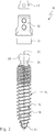
- FIGS. 1 to 4 show a generally designated by the reference numeral 10, designed as a pedicle screw, in particular as a polyaxial screw according to the invention osteosynthesis device 10.
- FIG. 1 shows the osteosynthesis device 10 in an oblique view from below.
- FIG. 2 shows the osteosynthesis device 10 in a side view looking in the direction of the arrow 12 in FIG. 1 in an exploded view.
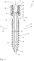
- FIG. 3 shows the osteosynthesis device 10 in the side view according to FIG. 2 in an unexploded view and
- FIG. 4 shows a section through the osteosynthesis device 10 along the line AA according to FIG. 3 ,
- the osteosynthesis device 10 comprises a bone anchor 14 designed as a bone screw, which has a shaft 16 with an external thread 18.
- a bone anchor 14 designed as a bone screw, which has a shaft 16 with an external thread 18.
- the bone anchor 14 may further comprise transverse bores, not shown in the figures, which are connected to the longitudinal bore 20.
- the shaft 16 has at one end a drill bit 24, by means of which the bone anchor 14 can be screwed into a bone.
- the bone anchor 14 At its end remote from the drill bit 24, the bone anchor 14 has a throat 26 formed as a constriction, to which a head 28 of the bone anchor 14 connects in the direction of the central longitudinal axis 22.
- the bone anchor 14 further comprises a torque transmitting portion 30 in the form of a hexagonal profile or Torxprofile, which is arranged concentrically to the central longitudinal axis 22 and by means of which the bone anchor 14 can be driven in rotation so that it can be screwed into a bone of a patient.
- the osteosynthesis device 10 further comprises an integrally formed clevis 32.
- the clevis 32 serves to receive the bone anchor 14, wherein the clevis 32 in a side view, which in section according to FIG. 4 is recognizable, U-shaped and has two legs 36 in a proximal end portion 34.
- the head 28 of the bone anchor 14 is pivotally mounted at a distal end portion 38 of the fork head 32 remote from the legs 36 in the manner of a spherical bearing and can be set relative to the clevis 32 at various positions to be set by a surgeon.
- the osteosynthesis device 10 in the interior 39 of the clevis 32 movably compressed pressure piece 40 which is axially movable in a defined range.
- clamping elements such as a grub screw and a clevis 32 between the legs 36, also not shown correction rod
- a clamping force on the pressure piece 40 in the direction an arrow 42 is exerted, so that the pressure piece 40 in turn presses on the head 28 of the bone anchor 14.
- the clevis 32 has an internal thread 44 in the interior 39 in the proximal end region 34.
- a known correction rod is inserted, by tightening the clamping member, the entire assembly is fixed, which typically only happens when the bone anchor 14 in its intended position in the bone a patient is introduced.
- the clevis 32 and the inserted into the interior 39 of the clevis 32 correction rod are aligned relative to the bone anchor 14 and fixed in the surgeon's intended position by tightening the clamping member.
- the clevis 32 has at the distal end portion 38 a receiving opening 46 for the head 28 of the bone anchor 14, wherein the head 28 of the bone anchor 14 from the distal End of the clevis 32 is inserted into the receiving opening 46.
- the clevis 32 is in the FIGS. 5 to 7 shown in isolation, wherein the operation of the osteosynthesis device 10 according to the invention based on the FIGS. 4 to 7 will be described and explained in detail.
- the clevis 32 has the receiving opening 46 for the head 28 of the bone anchor 14 at its distal end region.
- the receiving opening 46 is bounded in the radial direction by elastic spring sections 48, which in turn are bounded radially on the outside by a cylindrical annular groove 50 arranged concentrically with the receiving opening 46.
- annular groove 50 a formed as an annular cylindrical locking sleeve locking element 52 is pressed, which in the FIGS. 1 . 2 and 4 is clearly visible.
- the securing element 52 corresponds to the annular groove 50 such that, although it is arranged captively in the annular groove 50, it exerts no or virtually no radial clamping force on the spring sections 48.
- the securing element 52 may also be formed as an oval locking sleeve, wherein the groove may also be formed oval, so that a rotation inhibition of the locking sleeve in the oval groove can be achieved.
- the receiving opening 46 is bounded radially on the outside by a circular ring section 54 which forms the spring sections 48.
- the circular ring portion 54 on its circumference arranged recesses 56 which extend parallel to a central axis of the receiving opening 46 and divide the circular ring portion 54 in the spring portions 48.
- the head 28 of the bone anchor 14 is formed spherical, wherein the spring portions 48 radially projecting towards the receiving opening 46 projecting retaining projections 58 which prevent falling out of the head 28 of the bone anchor 14 from the receiving opening 46.
- the retaining projections 58 have a sliding section 60 which is designed such that the head 28 of the bone anchor 14 can be pivoted in the direction of the double arrow 62.
- the sliding portion 14 is concave spherical, so that the spherical head 28 of the bone anchor 14 can slide on it.
- the spring sections 48 have, at the distal end region 38, an insertion bevel 64 which faces radially towards the receiving opening 46.
- the shaft 16 of the bone anchor 14 has an outer diameter 66 on the external thread 16, the receiving opening 46 having an opening diameter 68.
- the outer diameter 66 of the shaft 16 is larger at its largest dimension than the inner diameter of the receiving opening 46, so that the bone anchor 14 is not from above, i. can be inserted through the receiving opening 46 from the proximal end 34.
- the spring sections 48 are secured in the blocking position by arranging the securing element 52 in the annular groove 50.
- the securing element 52 which is arranged captively, for example, by pressing in the annular groove 50, only prevents the spring sections 48 can be moved radially outward into the release position. Exerting radial clamping force on the head 28 of the bone anchor 14 by the spring portions 48 is not desired according to the invention.
- the spring portions 48 asymmetrically form such that in one direction a greater deflection can be realized as in an opposite direction.
Description
Die Erfindung betrifft eine Osteosynthesevorrichtung, insbesondere eine Pedikelschraube, mit den Merkmalen des Oberbegriffs des Anspruchs 1.The invention relates to an osteosynthesis device, in particular a pedicle screw, having the features of the preamble of claim 1.
Derartige Osteosynthesevorrichtungen sind aus dem Stand der Technik vielfach bekannt. Osteosynthesevorrichtungen betreffen insbesondere das Gebiet der Wirbelsäulenchirurgie, um benachbarte Wirbelkörper auszurichten und in einer gewünschten Position relativ zueinander zu fixieren. Hierbei wird in benachbarte Wirbelkörper jeweils ein Knochenanker eingebracht, und zwar typischerweise als Knochenschraube eingeschraubt, und es werden dann diese benachbarten Knochenanker über ein Korrekturelement, typischerweise über einen Korrekturstab verbunden, der in dem Gabelkopf einer jeweiligen Osteosynthesevorrichtung in einer bestimmten und von einem Chirurgen erwünschten Position geklemmt wird. Auf diese Weise werden benachbarte Wirbelkörper ausgerichtet und in einer gewünschten Position relativ zueinander fixiert.Such osteosynthesis devices are widely known from the prior art. Osteosynthesis devices particularly relate to the field of spinal surgery to align adjacent vertebral bodies and fix them in a desired position relative to one another. In this case, a respective bone anchor is introduced into adjacent vertebral bodies, typically screwed in as a bone screw, and then these adjacent bone anchors are connected via a correction element, typically via a correction rod, in the clevis of a respective osteosynthesis device in a particular and a Surgeons desired position is clamped. In this way, adjacent vertebrae are aligned and fixed in a desired position relative to each other.
Eine derartige Osteosynthesevorrichtung ist beispielsweise aus der
Nachteilig an derartigen Osteosynthesevorrichtungen ist jedoch, dass die Schaftdurchmesser der Knochenanker bzw. Knochenschrauben, die ein Außengewinde zum Einschrauben in einen Knochen oder Wirbelkörper aufweisen, in ihrer Größe begrenzt sind. So ist es nicht möglich, einen Knochenanker bzw. eine Knochenschraube mit einem Schaftdurchmesser, der größer ist als der Durchmesser des Kopfes, vom proximalen Ende des Gabelkopfs in die Aufnahmeöffnung einzusetzen. Für Anwendungen, die einen großen Schaftdurchmesser erfordern, lassen sich derartige Osteosynthesevorrichtungen daher nicht verwenden.However, a disadvantage of such osteosynthesis devices is that the shaft diameter of the bone anchors or bone screws, which have an external thread for screwing into a bone or vertebral body, are limited in their size. So it is not possible, a bone anchor or a bone screw with a shaft diameter that is larger than the diameter of the head, from the proximal Insert the end of the clevis into the receiving opening. Therefore, for applications requiring a large shaft diameter, such osteosynthesis devices can not be used.
Aus dem Stand der Technik sind ferner Osteosynthesevorrichtungen bekannt, bei denen ein Kopf eines Knochenankers bzw. einer Knochenschraube von einem distalen Ende in den Gabelkopf der Osteosynthesevorrichtung eingesetzt sind. Eine derartige Osteosynthesevorrichtung ist aus der
Nachteilig an einer derartigen Osteosynthesevorrichtung ist jedoch, dass eine Korrektur der Winkeleinstellung durch einen Chirurgen nach dem erstmaligen Anziehen der Madenschraube nicht oder nur schwer möglich ist, da der Klemmring auf der konischen Außenoberfläche des Klemmteils bereits verklemmt ist. Ein Lösen der Madenschraube bewirkt somit nicht unmittelbar ein Lösen der Winkellage der Knochenschraube relativ zum Gabelkopf. Dies erweist sich insbesondere bei bereits in Knochen oder Wirbelkörper eingeschraubten Knochenschrauben als problematisch. Ferner ist die mehrteilige Ausbildung des Gabelkopfs kompliziert in der Montage und teuer in der Herstellung.A disadvantage of such an osteosynthesis device, however, is that a correction of the angle adjustment by a surgeon after initial tightening the grub screw is not or only with difficulty, since the clamping ring is already jammed on the conical outer surface of the clamping part. Loosening the grub screw thus does not directly cause a loosening of the angular position of the bone screw relative to the clevis. This proves to be problematic especially in bone screws already screwed into bone or vertebral bodies. Furthermore, the multi-part design of the clevis is complicated to assemble and expensive to manufacture.
Die Erfindung stellt sich daher die Aufgabe, eine Osteosynthesevorrichtung bereitzustellen, mit der große Schaftdurchmesser der Knochenanker einfach und kostengünstig realisierbar sind, wobei eine einfache Korrektur der Winkellage des Knochenankers gewährleistet werden soll.The invention therefore has the task of providing an osteosynthesis device, with the large shaft diameter of the bone anchor can be realized easily and inexpensively, with a simple correction of the angular position of the bone anchor is to be ensured.
Diese Aufgabe wird durch eine Osteosynthesevorrichtung mit den Merkmalen des Anspruchs 1 gelöst. Diese Osteosynthesevorrichtung zeichnet sich dadurch aus, dass die Federabschnitte radial außen von einer konzentrisch zur Aufnahmeöffnung angeordneten Ringnut begrenzt werden, die eine Aufnahme für ein Sicherungselement bildet.This object is achieved by an osteosynthesis device having the features of claim 1. This osteosynthesis device is characterized in that the spring portions are bounded radially on the outside by a concentric with the receiving opening arranged annular groove, which forms a receptacle for a securing element.
Vorzugsweise sind die Federabschnitte nach radial außen derart federnd ausgebildet, dass die Aufnahmeöffnung zum Einsetzten des Kopfs des Knochenankers kurzzeitig radial aufgeweitet wird. Wenn kein Sicherungselement in die Ringnut eingesetzt ist, können die Federabschnitte von einer Sperrlage in eine Einführlage bewegt werden. Besonders bevorzugt ist es dabei, wenn die Federabschnitte elastisch verformbar ausgebildet sind, so dass sie nach ihrer Verformung wieder in die Sperrlage zurückbewegt werden können. Vorteilhafterweise ist die Verbindung zwischen den Federabschnitten des Gabelkopfs und dem Kopf des Knochenankers als Biegeschnappverbindung und/oder Ringschnappverbindung ausgebildet.Preferably, the spring portions are radially outwardly so resiliently formed that the receiving opening for inserting the head of the bone anchor is briefly expanded radially. If no securing element is inserted into the annular groove, the spring sections can be moved from a blocking position into an insertion position. It is particularly preferred if the spring sections are elastically deformable, so that they can be moved back into their locked position after their deformation. Advantageously, the connection between the spring sections of the clevis and the head of the bone anchor is designed as Biegeschnappverbindung and / or Ringschnappverbindung.
Erfindungsgemäß ist ein Sicherungselement vorgesehen, das in der Ringnut verliersicher angeordnet ist.According to the invention, a securing element is provided which is arranged captively in the annular groove.
Erfindungsgemäß ist ferner vorgesehen, dass die Ringnut zylindrisch ausgebildet ist. Eine zylindrische Ringnut erweist sich als besonders vorteilhaft, da durch axiales Einführen oder Einsetzen eines Sicherungselements in die Ringnut eine radiale Verlagerung der Federabschnitte weitgehend oder nahezu weitgehend verhindert werden kann, so dass durch Einsetzen des Sicherungselements lediglich ein Verlagern der Federabschnitte in die Einführlage verhindert werden kann, wobei ein Klemmen des Kopfs des Knochenankers durch Anordnen des Sicherungselements in der Ringnut vermieden werden kann.According to the invention it is further provided that the annular groove is cylindrical. A cylindrical annular groove proves to be particularly advantageous because by axial insertion or insertion of a securing element in the annular groove radial displacement of the spring sections can be largely or almost largely prevented, so that only a displacement of the spring sections can be prevented in the insertion position by inserting the securing element wherein clamping of the head of the bone anchor can be avoided by placing the securing element in the annular groove.
Erfindungsgemäß ist darüber hinaus vorgesehen, dass das Sicherungselement als kreisringartige, vorzugsweise zylindrische Sperrhülse ausgebildet ist und in der Ringnut befestigt ist und verhindert, dass die Federabschnitte nach radial außen bewegt werden können. Hierzu weist die Sperrhülse vorzugweise einen Querschnitt auf, der gleich oder nahezu gleich dem Durchmesser der Ringnut ist. Die Sperrhülse korrespondiert dabei vorteilhafterweise derart mit der zylindrischen Ringnut, dass die Federabschnitte in der Sperrlage gesichert sind und bei in der Ringnut befestigter Sperrhülse nicht in die Freigabelage bewegt werden können, wobei gleichzeitig ein Herausfallen der Sperrhülse aus der Ringnut verhindert werden kann und wobei keine oder nahezu keine Klemmung des Kopfs des Knochenankers durch die Federabschnitte bzw. die Sperrhülse erfolgt. Besonders bevorzugt ist es daher, wenn ein Verklemmen des Kopfs des Knochenankers lediglich durch ein in den Gabelkopf vom proximalen Ende eingesetztes Druckstück erfolgt, das im Gabelkopf verpresst ist und bei der Montage eines Korrekturelements bzw. Korrekturstabs derart axial gegen den Kopf des Knochenankers beaufschlagt wird, dass dieser in seiner jeweiligen Winkelauslenkung fixiert wird.According to the invention it is further provided that the securing element is designed as an annular, preferably cylindrical locking sleeve and is secured in the annular groove and prevents the spring portions can be moved radially outward. For this purpose, the locking sleeve preferably has a cross-section which is equal to or almost equal to the diameter of the annular groove. The locking sleeve corresponds advantageously in such a way with the cylindrical annular groove, that the spring sections are secured in the locked position and can not be moved into the release position when mounted in the annular groove locking sleeve, at the same time falling out of Locking sleeve can be prevented from the annular groove and wherein there is no or almost no clamping of the head of the bone anchor by the spring sections or the locking sleeve. It is therefore particularly preferred if jamming of the head of the bone anchor takes place only by a pressure piece inserted into the clevis from the proximal end, which is compressed in the clevis and is thus acted upon axially against the head of the bone anchor during assembly of a correction element or correction rod. that this is fixed in its respective angular displacement.
Vorteilhafterweise erfolgt die Befestigung der Sperrhülse durch Einpressen, Verklemmen, Verkleben, Vernieten, Verschweißen oder Verschrauben. Es ist auch denkbar, dass die Ringnut und/oder die Sperrhülse wenigstens eine konische Fläche aufweisen, die derart ausgebildet ist, dass eine verliersichere Befestigung der Sperrhülse in der Ringnut erleichtert ist.Advantageously, the attachment of the locking sleeve by pressing, jamming, gluing, riveting, welding or screwing takes place. It is also conceivable that the annular groove and / or the locking sleeve have at least one conical surface, which is designed such that a captive attachment of the locking sleeve is facilitated in the annular groove.
Eine weitere vorteilhafte Ausgestaltung der Osteosynthesevorrichtung sieht vor, dass die Aufnahmeöffnung nach radial außen von einem Kreisringabschnitt begrenzt wird, der die Federabschnitte bildet. Vorteilhafterweise ist der Kreisringabschnitt dann zwischen der Aufnahmeöffnung und der Ringnut angeordnet.A further advantageous embodiment of the osteosynthesis device provides that the receiving opening is bounded radially outward by a circular ring section which forms the spring sections. Advantageously, the circular ring portion is then arranged between the receiving opening and the annular groove.
Besonders vorteilhaft ist es dabei, wenn der Kreisringabschnitt über seinen Umfang angeordnete Ausnehmungen aufweist, die den Kreisringabschnitt in die Federabschnitte unterteilen. Vorteilhafterweise sind die Federabschnitte am proximalen Ende mit dem Gabelkopf einstückig verbunden und weisen am distalen Ende ein freies Ende auf. Vorzugsweise sind mehrere, weiter vorzugsweise 4 bis 8, weiter vorzugsweise 6 Ausnehmungen vorgesehen.It is particularly advantageous if the circular ring section has recesses arranged over its circumference, which divide the circular ring section into the spring sections. Advantageously, the spring sections are integrally connected at the proximal end of the fork head and have a free at the distal end End up. Preferably, a plurality, more preferably 4 to 8, further preferably 6 recesses are provided.
In einer bevorzugten Weiterbildung der Osteosynthesevorrichtung ist vorgesehen, dass die Ausnehmungen parallel zu einer Mittenachse der Aufnahmeöffnung verlaufen. Dabei ist denkbar, dass die Ausnehmungen zylindrisch ausgebildet sind.In a preferred development of the osteosynthesis device, it is provided that the recesses run parallel to a center axis of the receiving opening. It is conceivable that the recesses are cylindrical.
In einer weiteren besonders vorteilhaften Weiterbildung der Osteosynthesevorrichtung ist vorgesehen, dass die Aufnahmeöffnung einen Öffnungsdurchmesser aufweist und dass der Schaft des Knochenankers einen Außendurchmesser aufweist, wobei der Öffnungsdurchmesser der Aufnahmeöffnung kleiner ist als der größte Außendurchmesser des Schafts. Mit einer derartigen Osteosynthesevorrichtung, kann folglich ein Knochenanker mit einem Schaft mit großem Außendurchmesser realisiert werden, wobei der Knochenanker beispielsweise auch in spröden Knochen oder Wirbelkörpern sicher befestigt werden kann.In a further particularly advantageous embodiment of the osteosynthesis device, it is provided that the receiving opening has an opening diameter and that the shaft of the bone anchor has an outer diameter, wherein the opening diameter of the receiving opening is smaller than the largest outer diameter of the shaft. With such an osteosynthesis device, therefore, a bone anchor can be realized with a shaft having a large outer diameter, wherein the bone anchor can be securely fixed, for example, even in brittle bones or vertebral bodies.
Als besonders vorteilhaft hat es sich ferner erwiesen, wenn der Kopf des Knochenankers kugelig ausgebildet ist und wenn die Federabschnitte radial zur Aufnahmeöffnung hin ragende, Haltevorsprünge aufweisen. Vorteilhafterweise sind die Haltevorsprünge derart ausgebildet, dass sie ein Herausfallen des Kopfs aus dem Knochenanker in axialer Richtung verhindern.It has also proved to be particularly advantageous if the head of the bone anchor is designed to be spherical and if the spring sections have holding projections which protrude radially to the receiving opening. Advantageously, the retaining projections are designed such that they prevent falling out of the head from the bone anchor in the axial direction.
Besonders vorteilhaft ist es dabei, wenn die Haltevorsprünge einen Gleitabschnitt aufweisen, der derart ausgelegt ist, dass der Kopf des Knochenankers verschwenkbar ist. Vorteilhafterweise weisen die Haltevorsprünge eine dem distalen Ende zugewandte, konkav ballige Fläche auf, die derart ausgebildet ist, dass der Kopf einerseits verschwenkbar im Gabelkopf gelagert ist und andererseits ein Herausfallen des Kopfs aus dem Gabelkopf verhindert ist.It is particularly advantageous if the holding projections have a sliding portion which is designed such that the head of the bone anchor is pivotable. Advantageously, the retaining projections have a concave, facing the distal end spherical surface which is formed such that the head is pivotally mounted on the one hand in the clevis and on the other hand falling out of the head is prevented from the clevis.
Besonders bevorzugt ist es ferner, wenn die Federabschnitte am distalen Endbereich eine der Aufnahmeöffnung radial zugewandte Einführschräge aufweisen. Mittels einer derartigen Einführschräge kann ein Eindrücken oder Einpressen des Kopfs des Knochenankers bei der Montage der Osteosynthesevorrichtung erleichtert werden.It is further particularly preferred if the spring sections at the distal end region have an insertion bevel radially facing the receiving opening. By means of such an insertion be a depression or pressing of the head of the bone anchor during assembly of the osteosynthesis device can be facilitated.
Weiterhin ist es vorteilhaft, wenn die Federabschnitte in axialer Richtung unterschiedlich lang ausgebildet sind. Vorteilhafterweise sind die Federabschnitte unsymmetrisch derart ausgebildet, dass in einer ersten Auslenkungsrichtung eine größere Auslenkung realisiert werden kann als in einer von der ersten Auslenkungsrichtung verschiedenen zweiten Auslenkungsrichtung.Furthermore, it is advantageous if the spring portions are formed differently long in the axial direction. Advantageously, the spring sections are asymmetrically designed such that a greater deflection can be realized in a first deflection direction than in a second deflection direction different from the first deflection direction.
Weitere Einzelheiten und vorteilhafte Weiterbildungen sind der nachfolgenden Beschreibung zu entnehmen, anhand derer die in den Figuren dargestellte Ausführungsform näher beschrieben und erläutert ist.Further details and advantageous developments are apparent from the following description, with reference to which the embodiment shown in the figures is described and explained in detail.
Es zeigen:
-
Figur 1 eine Schrägansicht von unten auf eine erfindungsgemäße Osteosynthesevorrichtung in einer Explosionsdarstellung; -
Figur 2 eine Seitenansicht der Osteosynthesevorrichtung gemäßFigur 1 in Explosionsdarstellung; -
Figur 3 die Seitenansicht der Osteosynthesevorrichtung gemäßFigur 2 in nicht explodierter Darstellung; -
Figur 4 einen Schnitt durch die Osteosynthesevorrichtung entlang der Linie A-A gemäßFigur 3 ; -
Figur 5 eine Schrägansicht eines Gabelkopfs der Osteosynthesevorrichtung gemäß derFiguren 1 bis 4 ; -
Figur 6 eine Seitenansicht des Gabelkopfs gemäßFigur 5 ; und -
Figur 7 einen Schnitt durch den Gabelkopf entlang der Linie B-B gemäßFigur 6 .
-
FIG. 1 an oblique view from below of an osteosynthesis device according to the invention in an exploded view; -
FIG. 2 a side view of the osteosynthesis device according toFIG. 1 in exploded view; -
FIG. 3 the side view of the osteosynthesis device according toFIG. 2 in unexploded view; -
FIG. 4 a section through the osteosynthesis device along the line AA according toFIG. 3 ; -
FIG. 5 an oblique view of a clevis of the osteosynthesis device according to theFIGS. 1 to 4 ; -
FIG. 6 a side view of the fork head according toFIG. 5 ; and -
FIG. 7 a section through the clevis along the line BB according toFIG. 6 ,
Die
Die Osteosynthesevorrichtung 10 umfasst einen als Knochenschraube ausgebildeten Knochenanker 14, der einen Schaft 16 mit einem Außengewinde 18 aufweist. Der Knochenanker 14 bzw. dessen Schaft 16 ist kanüliert ausgebildet, d.h. er weist eine durchgehende Längsbohrung 20 auf, die konzentrisch zu einer Mittellängsachse 22 des Knochenankers 14 bzw. des Schafts 16 angeordnet ist. Der Knochenanker 14 kann ferner in den Figuren nicht dargestellte Querbohrungen aufweisen, die mit der Längsbohrung 20 verbunden sind. Mittels der Längsbohrung 20 und der Querbohrungen kann Knochenzement zwischen dem Schaft 16 und einem Knochen eines Patienten ausgebracht werden. Der Schaft 16 weist an einem Ende eine Bohrspitze 24 auf, mittels derer der Knochenanker 14 in einen Knochen eingeschraubt werden kann. An seinem der Bohrspitze 24 abgewandten Ende weist der Knochenanker 14 einen als Einschnürung ausgebildeten Hals 26 auf, an den sich in Richtung der Mittellängsachse 22 ein Kopf 28 des Knochenankers 14 anschließt. Im Kopf 28 weist der Knochenanker 14 ferner einen Drehmomentübertragungsabschnitt 30 in Form eines Sechskantprofils oder Torxprofils auf, der konzentrisch zur Mittellängsachse 22 angeordnet ist und mittels dessen der Knochenanker 14 rotierend angetrieben werden kann, so dass er in einen Knochen eines Patienten eingeschraubt werden kann.The
Die Osteosynthesevorrichtung 10 umfasst ferner einen einstückig ausgebildeten Gabelkopf 32. Der Gabelkopf 32 dient zur Aufnahme des Knochenankers 14, wobei der Gabelkopf 32 in einer Seitenansicht, die im Schnitt gemäß
Hierfür weist die Osteosynthesevorrichtung 10 im Inneren 39 des Gabelkopfs 32 beweglich verpresstes Druckstück 40 auf, das axial in einem definierten Bereich beweglich ist. Zur Festlegung einer Verschwenkung des Knochenankers 14 wird vom proximalen Endbereich 34 des Gabelkopfs 32 ausgehend, mittels nicht dargestellter Klemmelemente, wie bspw. einer Madenschraube und eines im Gabelkopf 32 zwischen den Schenkeln 36 angeordneten, ebenfalls nicht dargestellten Korrekturstabs eine Klemmkraft auf das Druckstück 40 in Richtung eines Pfeils 42 ausgeübt, so dass das Druckstück 40 wiederum auf den Kopf 28 des Knochenankers 14 drückt.For this purpose, the
Zur Aufnahme eines als bspw. Madenschraube ausgebildeten Klemmelements weist der Gabelkopf 32 im proximalen Endbereich 34 im Inneren 39 ein Innengewinde 44 auf. Vor dem Anziehen des Klemmelements wird zwischen dem Kopf 28 des Knochenankers 14 und dem Klemmelement ein an sich bekannter Korrekturstab eingelegt, wobei durch Festziehen des Klemmelements die gesamte Anordnung fixierbar ist, was typischerweise erst geschieht, wenn der Knochenanker 14 in seiner bestimmungsgemäßen Position in den Knochen eines Patienten eingebracht ist. Nach Einbringen des Knochenankers 14 werden der Gabelkopf 32 und der in das Innere 39 des Gabelkopfs 32 eingelegte Korrekturstab relativ zum Knochenanker 14 ausgerichtet und in der vom Chirurgen intendierten Position durch Festziehen des Klemmelements fixiert.To accommodate a clamping element designed as a grub screw, for example, the
Der Gabelkopf 32 weist am distalen Endbereich 38 eine Aufnahmeöffnung 46 für den Kopf 28 des Knochenankers 14 auf, wobei der Kopf 28 des Knochenankers 14 vom distalen Ende des Gabelkopfs 32 in die Aufnahmeöffnung 46 eingesetzt ist.The
Der Gabelkopf 32 ist in den
In die Ringnut 50 ist ein als kreisringartige zylindrische Sperrhülse ausgebildetes Sicherungselement 52 eingepresst, das in den
Die Aufnahmeöffnung 46 wird radial außen von einem Kreisringabschnitt 54 begrenzt, der die Federabschnitte 48 bildet. Hierzu weist der Kreisringabschnitt 54 über seinen Umfang angeordnete Ausnehmungen 56 auf, die parallel zu einer Mittenachse der Aufnahmeöffnung 46 verlaufen und den Kreisringabschnitt 54 in die Federabschnitte 48 unterteilen.The receiving
Ferner ist der Kopf 28 des Knochenankers 14 kugelig ausgebildet, wobei die Federabschnitte 48 radial zur Aufnahmeöffnung 46 hin ragende Haltevorsprünge 58 aufweisen, die ein Herausfallen des Kopfs 28 des Knochenankers 14 aus der Aufnahmeöffnung 46 verhindern. Die Haltevorsprünge 58 weisen einen Gleitabschnitt 60 auf, der derart ausgelegt ist, dass der Kopf 28 des Knochenankers 14 in Richtung des Doppelpfeils 62 verschwenkbar ist. Der Gleitabschnitt 14 ist konkav ballig ausgebildet, so dass der kugelige Kopf 28 des Knochenankers 14 auf ihm gleiten kann. Die Federabschnitte 48 weisen am distalen Endbereich 38 eine der Aufnahmeöffnung 46 radial zugewandte Einführschräge 64 auf.Furthermore, the
Der Schaft 16 des Knochenankers 14 weist am Außengewinde 16 einen Außendurchmesser 66 auf, wobei die Aufnahmeöffnung 46 einen Öffnungsdurchmesser 68 aufweist. Der Außendurchmesser 66 des Schafts 16 ist an seiner größten Abmessung größer als der Innendurchmesser der Aufnahmeöffnung 46, so dass der Knochenanker 14 nicht von oben, d.h. vom proximalen Endbereich 34 her durch die Aufnahmeöffnung 46 hindurchgesteckt werden kann.The
Die Montage der Osteosynthesevorrichtung 10 erfolgt folgendermaßen:
Der Knochenanker 14 wird vom distalen Endbereich 34 des Gabelkopfs 32 derart indie Aufnahmeöffnung 46 des Gabelkopfs 32 eingedrückt oder eingepresst, dass die elastischen Federabschnitte 48 nach radial außen in eine Einführlage bewegt werden und indie Ringnut 50 ausweichen. Zu diesem Zeitpunktist das Sicherungselement 52 noch nicht in derRingnut 50 montiert. Nach dem Eindrücken oder Einpressen des Kopfs 28 desKnochenankers 14 werden die Federabschnitte elastisch in die inFigur 4 dargestellte Sperrlage zurückbewegt,wobei die Haltevorsprünge 58den Kopf 28 desKnochenankers 14 axial derart hinterschneiden, dass ein Herausfallen des Knochenankers 14 aus der Aufnahmeöffnung 46 verhindert ist.
- The
bone anchor 14 is pressed or pressed by thedistal end portion 34 of theclevis 32 in the receivingopening 46 of theclevis 32 so that theelastic spring portions 48 are moved radially outward into an insertion position and dodge into theannular groove 50. At this time, the securingmember 52 is not yet mounted in theannular groove 50. After impressions or Pressing thehead 28 of thebone anchor 14, the spring portions are elastically in the inFIG. 4 shown blocked position, wherein the retainingprojections 58, thehead 28 of thebone anchor 14 undercut axially such that falling out of thebone anchor 14 is prevented from the receivingopening 46.
Nach dem Eindrücken oder Einpressen des Kopfs 28 des Knochenankers 14 in die Aufnahmeöffnung 46 werden die Federabschnitte 48 in der Sperrlage durch Anordnen des Sicherungselements 52 in der Ringnut 50 gesichert. Dabei verhindert das Sicherungselement 52, das beispielsweise durch Einpressen verliersicher in der Ringnut 50 angeordnet wird, lediglich, dass die Federabschnitte 48 nach radial außen in die Freigabelage bewegt werden können. Ein Ausüben von radialer Klemmkraft auf den Kopf 28 des Knochenankers 14 durch die Federabschnitte 48 ist erfindungsgemäß nicht erwünscht.After pressing or pressing the
Zur Festlegung einer axialen Verschwenkung des Knochenankers 14 relativ zum Gabelkopf 32 wird, wie eingangs beschrieben, vom proximalen Endbereich 34 eine Klemmkraft durch nicht dargestellte Klemmelemente bzw. einen nicht dargestellten Korrekturstab auf das Druckstück 40 ausgeübt, welches wiederum den Kopf 28 des Knochenankers in seiner jeweiligen, von einem Chirurgen festgelegten Lage sichert.Establishing an axial pivoting of the
Zur Realisierung einer unsymmetrischen Auslenkung des Knochenankers 14 kann ferner vorgesehen sein, die Federabschnitte 48 beispielsweise unsymmetrisch derart auszubilden, dass in einer Richtung eine größere Auslenkung realisiert werden kann als in eine gegenüberliegende Richtung.For realizing an asymmetrical deflection of the
Claims (9)
- Osteosynthesis device (10), in particular a pedicle screw, with a bone anchor (18) having a shaft (16) and a head (28), in particular a bone screw, and with a fork head (32) which is U-shaped in side view and has two legs (36) at a proximal end region (34) and is formed from one piece, wherein the head (28) of the bone anchor (14) is mounted pivotably at a distal end region (38) of the fork head (32) facing away from the legs (36), wherein the fork head (32) at the distal end region (38) has an opening (46) delimited in the radial direction by spring portions (48) for receiving the head (28) of the bone anchor (14), wherein the spring portions (48) are delimited radially inwardly by the receiving opening (46), wherein the head (28) of the bone anchor (14) is inserted in the receiving opening (46) from the distal end of the fork head (32), characterised in that the spring portions (48) are delimited radially outwardly by a ring groove (50) arranged concentrically to the receiving opening (46) and forming a receiver for a securing element (52), wherein the ring groove (50) is formed so as to be cylindrical, wherein a securing element (52) is provided which is arranged captively in the ring groove (50) and wherein the securing element (52) is configured as an annular, preferably cylindrical blocking sleeve and is secured in the ring groove (50) and prevents the spring portions (48) from being able to move radially outwardly.
- Osteosynthesis device (10) according to claim 1, characterised in that the receiving opening (46) is delimited radially outwardly by a circular ring portion (54) forming the spring portions (48).
- Osteosynthesis device (10) according to claim 2, characterised in that the ring portion (54) has recesses (56) arranged over its periphery which divide the ring portion (54) into the spring portions (48).
- Osteosynthesis device (10) according to claim 3, characterised in that the recesses (56) run parallel to a centre axis of the receiving opening (46).
- Osteosynthesis device (10) according to at least one of the preceding claims, characterised in that the receiving opening (46) has an opening diameter (68), and that the shaft (16) of the bone anchor (14) has an outer diameter (66), wherein the opening diameter (68) of the receiving opening (46) is smaller than the largest outer diameter (66) of the shaft (16).
- Osteosynthesis device (10) according to at least one of the preceding claims, characterised in that the head (28) of the bone anchor (14) is formed as a ball, and the spring portions (48) have retaining protrusions (58) protruding radially towards the receiving opening (46).
- Osteosynthesis device (10) according to claim 6, characterised in that the retaining protrusions (58) have a slide portion (16) which is configured such that the head (28) of the bone anchor (14) is pivotable.
- Osteosynthesis device (10) according to at least one of the preceding claims, characterised in that at the distal end region (38), the spring portions (48) have an insert chamfer (64) facing radially towards the receiving opening (46).
- Osteosynthesis device (10) according to at least one of the preceding claims, characterised in that the spring portions (48) are formed with different lengths in the axial direction.
Applications Claiming Priority (2)
| Application Number | Priority Date | Filing Date | Title |
|---|---|---|---|
| DE102015214384.8A DE102015214384B4 (en) | 2015-07-29 | 2015-07-29 | osteosynthesis |
| PCT/EP2016/062595 WO2017016717A1 (en) | 2015-07-29 | 2016-06-03 | Osteosynthesis device |
Publications (2)
| Publication Number | Publication Date |
|---|---|
| EP3215039A1 EP3215039A1 (en) | 2017-09-13 |
| EP3215039B1 true EP3215039B1 (en) | 2017-10-18 |
Family
ID=56112951
Family Applications (1)
| Application Number | Title | Priority Date | Filing Date |
|---|---|---|---|
| EP16727680.7A Active EP3215039B1 (en) | 2015-07-29 | 2016-06-03 | Osteosynthesis device |
Country Status (7)
| Country | Link |
|---|---|
| US (1) | US10595903B2 (en) |
| EP (1) | EP3215039B1 (en) |
| AU (1) | AU2016299100B2 (en) |
| CA (1) | CA2993878A1 (en) |
| DE (1) | DE102015214384B4 (en) |
| ES (1) | ES2654526T3 (en) |
| WO (1) | WO2017016717A1 (en) |
Families Citing this family (3)
| Publication number | Priority date | Publication date | Assignee | Title |
|---|---|---|---|---|
| CN108392256A (en) * | 2018-02-06 | 2018-08-14 | 何伟义 | A kind of improvement of pedicle nail to external spring type |
| DE102020003247A1 (en) | 2020-05-29 | 2021-12-02 | Mimeo Medical Gmbh | Modular osteosynthesis device for vertebrae |
| DE102020006464A1 (en) | 2020-10-21 | 2022-04-21 | Mimeo Medical Gmbh | Screw element optimized for 3D printing |
Family Cites Families (7)
| Publication number | Priority date | Publication date | Assignee | Title |
|---|---|---|---|---|
| US5964760A (en) * | 1996-10-18 | 1999-10-12 | Spinal Innovations | Spinal implant fixation assembly |
| US6254602B1 (en) * | 1999-05-28 | 2001-07-03 | Sdgi Holdings, Inc. | Advanced coupling device using shape-memory technology |
| FR2794637B1 (en) | 1999-06-14 | 2001-12-28 | Scient X | IMPLANT FOR OSTEOSYNTHESIS DEVICE, ESPECIALLY OF THE RACHIS |
| EP2022423B1 (en) * | 2007-07-31 | 2010-07-14 | BIEDERMANN MOTECH GmbH | Bone anchoring device |
| US8696717B2 (en) * | 2008-11-05 | 2014-04-15 | K2M, Inc. | Multi-planar, taper lock screw with additional lock |
| ES2417188T3 (en) | 2009-09-25 | 2013-08-06 | Biedermann Technologies Gmbh & Co. Kg | Bone anchoring device |
| EP2570090B1 (en) | 2011-09-15 | 2015-04-01 | Biedermann Technologies GmbH & Co. KG | Polyaxial bone anchoring device with enlarged pivot angle |
-
2015
- 2015-07-29 DE DE102015214384.8A patent/DE102015214384B4/en active Active
-
2016
- 2016-06-03 AU AU2016299100A patent/AU2016299100B2/en active Active
- 2016-06-03 ES ES16727680.7T patent/ES2654526T3/en active Active
- 2016-06-03 CA CA2993878A patent/CA2993878A1/en not_active Abandoned
- 2016-06-03 WO PCT/EP2016/062595 patent/WO2017016717A1/en active Application Filing
- 2016-06-03 US US15/747,984 patent/US10595903B2/en active Active
- 2016-06-03 EP EP16727680.7A patent/EP3215039B1/en active Active
Non-Patent Citations (1)
| Title |
|---|
| None * |
Also Published As
| Publication number | Publication date |
|---|---|
| ES2654526T3 (en) | 2018-02-14 |
| US10595903B2 (en) | 2020-03-24 |
| DE102015214384B4 (en) | 2018-12-27 |
| US20180214183A1 (en) | 2018-08-02 |
| CA2993878A1 (en) | 2017-02-02 |
| DE102015214384A1 (en) | 2017-02-02 |
| AU2016299100A1 (en) | 2018-03-15 |
| AU2016299100B2 (en) | 2020-10-08 |
| EP3215039A1 (en) | 2017-09-13 |
| WO2017016717A1 (en) | 2017-02-02 |
Similar Documents
| Publication | Publication Date | Title |
|---|---|---|
| DE10157814B4 (en) | Closure device for securing a rod-shaped element in a holding element connected to a shaft | |
| EP1261288B1 (en) | Connector element for bone rods or spinal rods | |
| EP2832308B1 (en) | Medical instrument for holding and handling a surgical fastening element and spine stabilising system | |
| EP2286747B1 (en) | Enchoring element and dynamic stabilisation device for vertebral bodies or bones | |
| DE10164323C1 (en) | Bone screw has holder element joined to shaft and possessing two free arms , with inner screw, slot, external nut, cavity and shoulder cooperating with attachment | |
| DE69925169T2 (en) | RADIAL EXPANDABLE BRAND NAIL | |
| EP1408859B1 (en) | Connecting element | |
| EP2753254A1 (en) | Polyaxial pedicle screw having provisional fastening | |
| EP1316295A2 (en) | Element with a shaft and a retaining element connected to the shaft for attaching a rod | |
| WO2001050968A1 (en) | Device for detachably clamping a longitudinal carrier in a surgical implant | |
| EP3215039B1 (en) | Osteosynthesis device | |
| EP3031416B1 (en) | Osteosynthesis device | |
| EP1827267B1 (en) | Orthopedic fixation device and orthopedic fixation system | |
| DE202016005347U1 (en) | Device for attaching a rod to a bone | |
| DE102017124734B4 (en) | polyaxial screw | |
| EP3331461B1 (en) | Handling instrument for a bone anchor | |
| WO2019073048A1 (en) | Instrument for connecting a correction rod to a bone screw | |
| DE202004018037U1 (en) | Device to be used for securing bone stabilizing element to bone screw, comprising single element for adjusting and fixing | |
| DE102017114267B4 (en) | Extension device for a bone anchor | |
| DE202007012643U1 (en) | Orthopedic retention system | |
| EP4051143A1 (en) | Medical decoupling instrument | |
| DE102015012909A1 (en) | Device for attaching a rod to a bone |
Legal Events
| Date | Code | Title | Description |
|---|---|---|---|
| GRAP | Despatch of communication of intention to grant a patent |
Free format text: ORIGINAL CODE: EPIDOSNIGR1 |
|
| GRAS | Grant fee paid |
Free format text: ORIGINAL CODE: EPIDOSNIGR3 |
|
| PUAI | Public reference made under article 153(3) epc to a published international application that has entered the european phase |
Free format text: ORIGINAL CODE: 0009012 |
|
| 17P | Request for examination filed |
Effective date: 20160922 |
|
| AK | Designated contracting states |
Kind code of ref document: A1 Designated state(s): AL AT BE BG CH CY CZ DE DK EE ES FI FR GB GR HR HU IE IS IT LI LT LU LV MC MK MT NL NO PL PT RO RS SE SI SK SM TR |
|
| GRAA | (expected) grant |
Free format text: ORIGINAL CODE: 0009210 |
|
| AK | Designated contracting states |
Kind code of ref document: B1 Designated state(s): AL AT BE BG CH CY CZ DE DK EE ES FI FR GB GR HR HU IE IS IT LI LT LU LV MC MK MT NL NO PL PT RO RS SE SI SK SM TR |
|
| REG | Reference to a national code |
Ref country code: GB Ref legal event code: FG4D Free format text: NOT ENGLISH |
|
| REG | Reference to a national code |
Ref country code: CH Ref legal event code: EP |
|
| REG | Reference to a national code |
Ref country code: AT Ref legal event code: REF Ref document number: 937262 Country of ref document: AT Kind code of ref document: T Effective date: 20171115 Ref country code: IE Ref legal event code: FG4D Free format text: LANGUAGE OF EP DOCUMENT: GERMAN |
|
| REG | Reference to a national code |
Ref country code: DE Ref legal event code: R096 Ref document number: 502016000219 Country of ref document: DE Ref country code: CH Ref legal event code: NV Representative=s name: DREISS PATENTANWAELTE PARTG MBB, DE |
|
| REG | Reference to a national code |
Ref country code: ES Ref legal event code: FG2A Ref document number: 2654526 Country of ref document: ES Kind code of ref document: T3 Effective date: 20180214 |
|
| REG | Reference to a national code |
Ref country code: NL Ref legal event code: MP Effective date: 20171018 |
|
| REG | Reference to a national code |
Ref country code: LT Ref legal event code: MG4D |
|
| PG25 | Lapsed in a contracting state [announced via postgrant information from national office to epo] |
Ref country code: NL Free format text: LAPSE BECAUSE OF FAILURE TO SUBMIT A TRANSLATION OF THE DESCRIPTION OR TO PAY THE FEE WITHIN THE PRESCRIBED TIME-LIMIT Effective date: 20171018 |
|
| PG25 | Lapsed in a contracting state [announced via postgrant information from national office to epo] |
Ref country code: FI Free format text: LAPSE BECAUSE OF FAILURE TO SUBMIT A TRANSLATION OF THE DESCRIPTION OR TO PAY THE FEE WITHIN THE PRESCRIBED TIME-LIMIT Effective date: 20171018 Ref country code: SE Free format text: LAPSE BECAUSE OF FAILURE TO SUBMIT A TRANSLATION OF THE DESCRIPTION OR TO PAY THE FEE WITHIN THE PRESCRIBED TIME-LIMIT Effective date: 20171018 Ref country code: NO Free format text: LAPSE BECAUSE OF FAILURE TO SUBMIT A TRANSLATION OF THE DESCRIPTION OR TO PAY THE FEE WITHIN THE PRESCRIBED TIME-LIMIT Effective date: 20180118 Ref country code: LT Free format text: LAPSE BECAUSE OF FAILURE TO SUBMIT A TRANSLATION OF THE DESCRIPTION OR TO PAY THE FEE WITHIN THE PRESCRIBED TIME-LIMIT Effective date: 20171018 |
|
| PG25 | Lapsed in a contracting state [announced via postgrant information from national office to epo] |
Ref country code: BG Free format text: LAPSE BECAUSE OF FAILURE TO SUBMIT A TRANSLATION OF THE DESCRIPTION OR TO PAY THE FEE WITHIN THE PRESCRIBED TIME-LIMIT Effective date: 20180118 Ref country code: LV Free format text: LAPSE BECAUSE OF FAILURE TO SUBMIT A TRANSLATION OF THE DESCRIPTION OR TO PAY THE FEE WITHIN THE PRESCRIBED TIME-LIMIT Effective date: 20171018 Ref country code: RS Free format text: LAPSE BECAUSE OF FAILURE TO SUBMIT A TRANSLATION OF THE DESCRIPTION OR TO PAY THE FEE WITHIN THE PRESCRIBED TIME-LIMIT Effective date: 20171018 Ref country code: GR Free format text: LAPSE BECAUSE OF FAILURE TO SUBMIT A TRANSLATION OF THE DESCRIPTION OR TO PAY THE FEE WITHIN THE PRESCRIBED TIME-LIMIT Effective date: 20180119 Ref country code: IS Free format text: LAPSE BECAUSE OF FAILURE TO SUBMIT A TRANSLATION OF THE DESCRIPTION OR TO PAY THE FEE WITHIN THE PRESCRIBED TIME-LIMIT Effective date: 20180218 Ref country code: HR Free format text: LAPSE BECAUSE OF FAILURE TO SUBMIT A TRANSLATION OF THE DESCRIPTION OR TO PAY THE FEE WITHIN THE PRESCRIBED TIME-LIMIT Effective date: 20171018 |
|
| REG | Reference to a national code |
Ref country code: DE Ref legal event code: R097 Ref document number: 502016000219 Country of ref document: DE |
|
| PG25 | Lapsed in a contracting state [announced via postgrant information from national office to epo] |
Ref country code: SK Free format text: LAPSE BECAUSE OF FAILURE TO SUBMIT A TRANSLATION OF THE DESCRIPTION OR TO PAY THE FEE WITHIN THE PRESCRIBED TIME-LIMIT Effective date: 20171018 Ref country code: DK Free format text: LAPSE BECAUSE OF FAILURE TO SUBMIT A TRANSLATION OF THE DESCRIPTION OR TO PAY THE FEE WITHIN THE PRESCRIBED TIME-LIMIT Effective date: 20171018 Ref country code: CZ Free format text: LAPSE BECAUSE OF FAILURE TO SUBMIT A TRANSLATION OF THE DESCRIPTION OR TO PAY THE FEE WITHIN THE PRESCRIBED TIME-LIMIT Effective date: 20171018 Ref country code: EE Free format text: LAPSE BECAUSE OF FAILURE TO SUBMIT A TRANSLATION OF THE DESCRIPTION OR TO PAY THE FEE WITHIN THE PRESCRIBED TIME-LIMIT Effective date: 20171018 |
|
| PLBE | No opposition filed within time limit |
Free format text: ORIGINAL CODE: 0009261 |
|
| STAA | Information on the status of an ep patent application or granted ep patent |
Free format text: STATUS: NO OPPOSITION FILED WITHIN TIME LIMIT |
|
| PG25 | Lapsed in a contracting state [announced via postgrant information from national office to epo] |
Ref country code: PL Free format text: LAPSE BECAUSE OF FAILURE TO SUBMIT A TRANSLATION OF THE DESCRIPTION OR TO PAY THE FEE WITHIN THE PRESCRIBED TIME-LIMIT Effective date: 20171018 Ref country code: SM Free format text: LAPSE BECAUSE OF FAILURE TO SUBMIT A TRANSLATION OF THE DESCRIPTION OR TO PAY THE FEE WITHIN THE PRESCRIBED TIME-LIMIT Effective date: 20171018 |
|
| 26N | No opposition filed |
Effective date: 20180719 |
|
| PG25 | Lapsed in a contracting state [announced via postgrant information from national office to epo] |
Ref country code: MT Free format text: LAPSE BECAUSE OF FAILURE TO SUBMIT A TRANSLATION OF THE DESCRIPTION OR TO PAY THE FEE WITHIN THE PRESCRIBED TIME-LIMIT Effective date: 20171018 |
|
| REG | Reference to a national code |
Ref country code: BE Ref legal event code: MM Effective date: 20180630 |
|
| REG | Reference to a national code |
Ref country code: IE Ref legal event code: MM4A |
|
| PG25 | Lapsed in a contracting state [announced via postgrant information from national office to epo] |
Ref country code: MC Free format text: LAPSE BECAUSE OF FAILURE TO SUBMIT A TRANSLATION OF THE DESCRIPTION OR TO PAY THE FEE WITHIN THE PRESCRIBED TIME-LIMIT Effective date: 20171018 Ref country code: LU Free format text: LAPSE BECAUSE OF NON-PAYMENT OF DUE FEES Effective date: 20180603 |
|
| PG25 | Lapsed in a contracting state [announced via postgrant information from national office to epo] |
Ref country code: FR Free format text: LAPSE BECAUSE OF NON-PAYMENT OF DUE FEES Effective date: 20180630 Ref country code: IE Free format text: LAPSE BECAUSE OF NON-PAYMENT OF DUE FEES Effective date: 20180603 |
|
| PG25 | Lapsed in a contracting state [announced via postgrant information from national office to epo] |
Ref country code: BE Free format text: LAPSE BECAUSE OF NON-PAYMENT OF DUE FEES Effective date: 20180630 |
|
| PG25 | Lapsed in a contracting state [announced via postgrant information from national office to epo] |
Ref country code: TR Free format text: LAPSE BECAUSE OF FAILURE TO SUBMIT A TRANSLATION OF THE DESCRIPTION OR TO PAY THE FEE WITHIN THE PRESCRIBED TIME-LIMIT Effective date: 20171018 |
|
| PG25 | Lapsed in a contracting state [announced via postgrant information from national office to epo] |
Ref country code: PT Free format text: LAPSE BECAUSE OF FAILURE TO SUBMIT A TRANSLATION OF THE DESCRIPTION OR TO PAY THE FEE WITHIN THE PRESCRIBED TIME-LIMIT Effective date: 20171018 |
|
| PG25 | Lapsed in a contracting state [announced via postgrant information from national office to epo] |
Ref country code: CY Free format text: LAPSE BECAUSE OF FAILURE TO SUBMIT A TRANSLATION OF THE DESCRIPTION OR TO PAY THE FEE WITHIN THE PRESCRIBED TIME-LIMIT Effective date: 20171018 Ref country code: HU Free format text: LAPSE BECAUSE OF FAILURE TO SUBMIT A TRANSLATION OF THE DESCRIPTION OR TO PAY THE FEE WITHIN THE PRESCRIBED TIME-LIMIT; INVALID AB INITIO Effective date: 20160603 Ref country code: RO Free format text: LAPSE BECAUSE OF FAILURE TO SUBMIT A TRANSLATION OF THE DESCRIPTION OR TO PAY THE FEE WITHIN THE PRESCRIBED TIME-LIMIT Effective date: 20171018 Ref country code: MK Free format text: LAPSE BECAUSE OF NON-PAYMENT OF DUE FEES Effective date: 20171018 |
|
| PG25 | Lapsed in a contracting state [announced via postgrant information from national office to epo] |
Ref country code: AL Free format text: LAPSE BECAUSE OF FAILURE TO SUBMIT A TRANSLATION OF THE DESCRIPTION OR TO PAY THE FEE WITHIN THE PRESCRIBED TIME-LIMIT Effective date: 20171018 |
|
| PG25 | Lapsed in a contracting state [announced via postgrant information from national office to epo] |
Ref country code: SI Free format text: LAPSE BECAUSE OF NON-PAYMENT OF DUE FEES Effective date: 20180603 |
|
| REG | Reference to a national code |
Ref country code: AT Ref legal event code: MM01 Ref document number: 937262 Country of ref document: AT Kind code of ref document: T Effective date: 20210603 |
|
| PG25 | Lapsed in a contracting state [announced via postgrant information from national office to epo] |
Ref country code: AT Free format text: LAPSE BECAUSE OF NON-PAYMENT OF DUE FEES Effective date: 20210603 |
|
| P01 | Opt-out of the competence of the unified patent court (upc) registered |
Effective date: 20230505 |
|
| PGFP | Annual fee paid to national office [announced via postgrant information from national office to epo] |
Ref country code: IT Payment date: 20230628 Year of fee payment: 8 Ref country code: GB Payment date: 20230606 Year of fee payment: 8 Ref country code: ES Payment date: 20230719 Year of fee payment: 8 Ref country code: CH Payment date: 20230702 Year of fee payment: 8 |
|
| PGFP | Annual fee paid to national office [announced via postgrant information from national office to epo] |
Ref country code: DE Payment date: 20230821 Year of fee payment: 8 |