EP3214976B1 - Capsule-based system for preparing and dispensing a beverage - Google Patents
Capsule-based system for preparing and dispensing a beverage Download PDFInfo
- Publication number
- EP3214976B1 EP3214976B1 EP15856702.4A EP15856702A EP3214976B1 EP 3214976 B1 EP3214976 B1 EP 3214976B1 EP 15856702 A EP15856702 A EP 15856702A EP 3214976 B1 EP3214976 B1 EP 3214976B1
- Authority
- EP
- European Patent Office
- Prior art keywords
- capsule
- cold
- hot
- beverage
- dispensing device
- Prior art date
- Legal status (The legal status is an assumption and is not a legal conclusion. Google has not performed a legal analysis and makes no representation as to the accuracy of the status listed.)
- Active
Links
Images












Classifications
-
- A—HUMAN NECESSITIES
- A47—FURNITURE; DOMESTIC ARTICLES OR APPLIANCES; COFFEE MILLS; SPICE MILLS; SUCTION CLEANERS IN GENERAL
- A47J—KITCHEN EQUIPMENT; COFFEE MILLS; SPICE MILLS; APPARATUS FOR MAKING BEVERAGES
- A47J31/00—Apparatus for making beverages
- A47J31/40—Beverage-making apparatus with dispensing means for adding a measured quantity of ingredients, e.g. coffee, water, sugar, cocoa, milk, tea
- A47J31/407—Beverage-making apparatus with dispensing means for adding a measured quantity of ingredients, e.g. coffee, water, sugar, cocoa, milk, tea with ingredient-containing cartridges; Cartridge-perforating means
-
- A—HUMAN NECESSITIES
- A47—FURNITURE; DOMESTIC ARTICLES OR APPLIANCES; COFFEE MILLS; SPICE MILLS; SUCTION CLEANERS IN GENERAL
- A47J—KITCHEN EQUIPMENT; COFFEE MILLS; SPICE MILLS; APPARATUS FOR MAKING BEVERAGES
- A47J31/00—Apparatus for making beverages
- A47J31/24—Coffee-making apparatus in which hot water is passed through the filter under pressure, i.e. in which the coffee grounds are extracted under pressure
- A47J31/34—Coffee-making apparatus in which hot water is passed through the filter under pressure, i.e. in which the coffee grounds are extracted under pressure with hot water under liquid pressure
- A47J31/36—Coffee-making apparatus in which hot water is passed through the filter under pressure, i.e. in which the coffee grounds are extracted under pressure with hot water under liquid pressure with mechanical pressure-producing means
- A47J31/3604—Coffee-making apparatus in which hot water is passed through the filter under pressure, i.e. in which the coffee grounds are extracted under pressure with hot water under liquid pressure with mechanical pressure-producing means with a mechanism arranged to move the brewing chamber between loading, infusing and ejecting stations
- A47J31/3623—Cartridges being employed
- A47J31/3633—Means to perform transfer from a loading position to an infusing position
-
- A—HUMAN NECESSITIES
- A47—FURNITURE; DOMESTIC ARTICLES OR APPLIANCES; COFFEE MILLS; SPICE MILLS; SUCTION CLEANERS IN GENERAL
- A47J—KITCHEN EQUIPMENT; COFFEE MILLS; SPICE MILLS; APPARATUS FOR MAKING BEVERAGES
- A47J31/00—Apparatus for making beverages
- A47J31/24—Coffee-making apparatus in which hot water is passed through the filter under pressure, i.e. in which the coffee grounds are extracted under pressure
- A47J31/34—Coffee-making apparatus in which hot water is passed through the filter under pressure, i.e. in which the coffee grounds are extracted under pressure with hot water under liquid pressure
- A47J31/36—Coffee-making apparatus in which hot water is passed through the filter under pressure, i.e. in which the coffee grounds are extracted under pressure with hot water under liquid pressure with mechanical pressure-producing means
- A47J31/3604—Coffee-making apparatus in which hot water is passed through the filter under pressure, i.e. in which the coffee grounds are extracted under pressure with hot water under liquid pressure with mechanical pressure-producing means with a mechanism arranged to move the brewing chamber between loading, infusing and ejecting stations
- A47J31/3623—Cartridges being employed
- A47J31/3628—Perforating means therefor
-
- A—HUMAN NECESSITIES
- A47—FURNITURE; DOMESTIC ARTICLES OR APPLIANCES; COFFEE MILLS; SPICE MILLS; SUCTION CLEANERS IN GENERAL
- A47J—KITCHEN EQUIPMENT; COFFEE MILLS; SPICE MILLS; APPARATUS FOR MAKING BEVERAGES
- A47J31/00—Apparatus for making beverages
- A47J31/24—Coffee-making apparatus in which hot water is passed through the filter under pressure, i.e. in which the coffee grounds are extracted under pressure
- A47J31/34—Coffee-making apparatus in which hot water is passed through the filter under pressure, i.e. in which the coffee grounds are extracted under pressure with hot water under liquid pressure
- A47J31/36—Coffee-making apparatus in which hot water is passed through the filter under pressure, i.e. in which the coffee grounds are extracted under pressure with hot water under liquid pressure with mechanical pressure-producing means
- A47J31/3666—Coffee-making apparatus in which hot water is passed through the filter under pressure, i.e. in which the coffee grounds are extracted under pressure with hot water under liquid pressure with mechanical pressure-producing means whereby the loading of the brewing chamber with the brewing material is performed by the user
- A47J31/3676—Cartridges being employed
- A47J31/369—Impermeable cartridges being employed
- A47J31/3695—Cartridge perforating means for creating the hot water inlet
-
- A—HUMAN NECESSITIES
- A47—FURNITURE; DOMESTIC ARTICLES OR APPLIANCES; COFFEE MILLS; SPICE MILLS; SUCTION CLEANERS IN GENERAL
- A47J—KITCHEN EQUIPMENT; COFFEE MILLS; SPICE MILLS; APPARATUS FOR MAKING BEVERAGES
- A47J31/00—Apparatus for making beverages
- A47J31/44—Parts or details or accessories of beverage-making apparatus
- A47J31/4482—Details allowing to adapt the beverage-making apparatus to the size of the brewing vessel or the beverage container, e.g. with adjustable support for the beverage container or adjustable hot water outlet
-
- A—HUMAN NECESSITIES
- A47—FURNITURE; DOMESTIC ARTICLES OR APPLIANCES; COFFEE MILLS; SPICE MILLS; SUCTION CLEANERS IN GENERAL
- A47J—KITCHEN EQUIPMENT; COFFEE MILLS; SPICE MILLS; APPARATUS FOR MAKING BEVERAGES
- A47J31/00—Apparatus for making beverages
- A47J31/44—Parts or details or accessories of beverage-making apparatus
- A47J31/4492—Means to read code provided on ingredient pod or cartridge
Definitions
- the present invention relates generally to beverage dispensing systems and more particularly to a complete beverage dispensing system that can dispense both cold and hot drinks.
- a beverage such as, for example, a cup of coffee or tea from a capsule.
- a disposable container fits on top of a cup and has a compartment for receiving a beverage extract such as coffee with a large reservoir on top into which a person must pour boiling water.
- These devices can be disposable but expensive, the coffee is exposed to the air where it can easily get stale or contaminated, and they are not generally suitable for automatic coffee making or other beverage machines. Because the flow rate of beverage is generally slow, these devices are typically large relative to the volume of beverage dispensed. Also, these devices can be designed to be used upright and only the bottom area is available for filtration flow and this contributes to the slowness of the filtration process.
- a filter is provided in a sealed receptacle and a support member is included intermediate the receptacle and filter which functions to support the filter.
- a support member is included intermediate the receptacle and filter which functions to support the filter.
- Omnifrio acquired by Primo Water
- Bevyz uses a pressure mechanism to pop open the capsule to enable a mixing process.
- the Esio Hot & Cold Beverage System uses a syrup pouch system and pumps drink mix out of the pouch to mix it with water outside of the packet. Yource by Brita uses a capsule based machine.
- WO 2013/119497 is the prior art closest to the invention and discloses a beverage dispensing device adapted to dispense both hot and cold beverages using one single beverage preparation mechanism and one single exit orifice.
- the present invention comprises a complete hot and cold beverage dispensing device comprising the features of claim 1. It is a machine with a compartment adapted to receive a drink mix capsule and a control panel that can display messages to a customer and allow the customer to choose drink options.
- the present invention also comprises a beverage preparation mechanism or sub-system to totally control the mechanical portion of hot and cold beverage preparation.
- a user To dispense a beverage, a user approaches the machine, places a cold drink capsule or a hot drink capsule into the compartment, closes the lid, and selects the type of drink on the control panel (or the selection may be made automatically by the system based on the type of capsule inserted).
- the machine opens the capsule when the machine cover is closed.
- An upper nozzle injects a small amount of cold liquid to mix with and dissolve (or dilute) the contents.
- a second nozzle begins to fill the vessel (cup) below an exit orifice.
- an internal mechanism rotates the capsule approximately ninety degrees to empty the contents of the capsule into the vessel.
- the cold drink capsules can contain a powder or a liquid which is mixed into the filtered water to produce the cold beverage.
- the drinks can be "house formulas" or common mass market branded beverages licensed from the manufacturers.
- the cold drink capsule is opened by cracking and peeling.
- This method of accessing the capsule offers an effective and efficient way to prepare and deliver the beverage.
- a mechanical device is adapted to crack the capsule along a crease punched into the capsule below the top cover of the capsule.
- the mechanical device peels open the capsule along the cracked crease typically when a user closes the lid.
- a slight crease could be included in a lip of the capsule or directly below it that can be used to break the seal and allow the cover to then be peeled or pried back.
- the cover is peeled back (e.g., tearing open the capsule) the drink is mixed with a mixing stream of liquid, which in many embodiments will be water, either cold or hot, sparkling or still.
- the capsule is punctured by a needle on the bottom by closing the lid. Closing the lid of the machine forces the hot drink capsule down on the needle. An injection needle arm rotates a needle into position that penetrates the lid of the capsule. A hot liquid is injected into the hot capsule to brew or mix the hot drink. The hot drink is forced out of the hole in its bottom by pressure via a hot drink spout into a cup.
- the hot drink capsule can contain powder, grind (such as ground coffee) or a liquid which is brewed or mixed with injected hot liquid such as hot filtered water.
- a purpose of the present invention is to offer a compelling alternative to bottled water and other water based ready-to-drink (RTD) beverages.
- the invention is meant to offer a convenient, reliable, and cost effective Point of Use solution to the consumer's hydration and beverage needs, both hot and cold.
- the invention is a single-serve beverage system that can produce unlimited chilled filtered water as well as single serve unique beverages through a cold capsule-based system.
- the present invention can dispense carbonated, flavored, enhanced, ultra purified filtered waters and flavors, hot coffee, hot and cold tea, hot chocolate and numerous other beverages both hot and cold..
- the present invention comprises a complete hot and cold beverage dispensing system. It also comprises a beverage preparation mechanism or sub-system that can be inserted and removed from a housing to totally control the mechanical portion of hot and cold beverage preparation.
- FIG. 1 An embodiment of a total beverage dispensing machine or system is shown in Fig. 1 and includes an outer housing (200) with a cover (201) containing a cold and hot water or other liquid supply, a controller that controls all aspects of beverage preparation and dispensing and the beverage preparation mechanism that actually dispenses the drink.
- the controller is in electrical communication with one or more user control panels (201) where messages can be displayed to the user, and the user can select various beverages. Selections may also be made with buttons (203).
- selection of a cold or hot drink is made solely on the basis of what type of capsule is inserted. Typical selections can be cold drinks such as fruit drinks, lemonade, other flavored cold drinks and the like, while hot beverages can include coffee, tea, hot chocolate and the like.
- the processor can be a microcontroller known in the art, a microprocessor, or any other type of processor or computer configured to store and execute stored instructions.
- the controller typically includes on-board and external memory. In some embodiments, the controller may have communication capability and be able to communicate status and receive commands over a network like the Internet.
- Cold beverage capsules are typically roughly diamond-shaped cups with a rim that seats a sealed lid.
- the cups can contain either powder or liquid cold drink mixes.
- Each cold capsule typically has a groove, score or indentation either on the rim or directly below the rim.
- the cold capsule can be opened by allowing the rim to encounter a protrusion on one of its ends. The upward force of the protrusion against the rim as the capsule rotates or moves downward causes part of the rim to tear open along the groove providing an opening where cold liquid can be injected into the capsule causing the mixed cold drink to exit the capsule and fill a cup below the mechanism.
- FIG. 2 shows an embodiment of a typical cold capsule.
- the hot capsules are similar to the familiar cups supplied by for coffee dispensing by several vendors.
- the hot capsules can contain other products besides just coffee including tea or hot chocolate for example, or any other hot drink.
- the housing (200) includes a base (300) and an access lid or cover (201) that allows insertion of a cold or hot capsule.
- a control panel (201) is also mounted on the housing (200) that allows a user to select and command preparation of a beverage.
- the housing (200) contains all necessary components including plumbing, liquid heating, control and sensing as well as a hot/cold beverage dispensing module or mechanism.
- Fig. 2A shows a typical cold capsule (302) with a rim (305) and lid (303).
- a protrusion (301) pries the rim (305) open when the capsule is forced to rotate downward while being captured with a fixed member (304).
- Fig. 2B shows the pried open cold capsule (302). While Fig. 2B shows the capsule being opened at both ends, a preferred way of opening the capsule is to open it only at one end. Either opening technique is within the scope of the present invention.
- Fig. 3 shows schematically the controller (203) which can be solid state controller chip known in the art.
- the controller (203) is electrically coupled to the control panel (202) which can be a touch panel, LCD panel or any other control panel of any type.
- the controller (203) is a processor that executes stored instructions that, in addition to reading and writing the control panel (202) also controls one or more drive motors (204) that are typically part of the mechanical drink preparation module (205).
- the controller (203) can command the drink preparation module (205) to either prepare and dispense a cold beverage or to prepare and dispense a hot beverage depending upon the user selection.
- the control panel (202) can display a message to insert the proper capsule in the preparation mechanism and to close the cover.
- the controller (203) can also receive an instruction about the size of the cup placed under the device and hence provide the correct amount of cold or hot fluid.
- the controller (203) receives sensor or camera information as to what type of capsule has been inserted and proceeds to prepare a cold or hot drink.
- the camera can read a label or barcode on the capsule.
- the cold or hot fluid is filtered water; however, it does not have to be water.
- Other fluids may be used with some drinks.
- the fluid can be carbonated water. Any fluid is within the scope of the present invention.
- the controller (203) can also control various pumps (206), heaters (207), and valves (208). In addition, it can read the temperature of the hot injection liquid with a temperature sensor (209).
- the controller (203) temperature sensor (209) and heater(s) (207) can operate in a closed-loop configuration.
- the controller (213) can read a sensor or camera (210) located near the capsule insertion point to determine whether a cold capsule or hot capsule (or any capsule) has been inserted.
- the sensor (210) may include two or more sensors, one to determine if anything at all has been inserted, and another to determine whether a cold or hot capsule has been inserted. There may be a camera (212) to read a label or barcode on the capsule . These may be infrared LED sensors or any other type of sensor. Further sensors (211) can optionally determine whether the cover is open or closed (seated) and the position of rotating members in the hot/cold dispensing module. If the cover is in the wrong position, the controller (203) can place an error message on the control panel (201).
- the present invention deploys an insertable beverage dispensing module or mechanism that can dispense cold beverages using the sealed capsule previously described and can dispense hot beverages using capsules similar to standard capsules known in the art for dispensing coffee.
- the cold beverage capsules may contain a powder or liquid mix for any cold drink; the hot capsules may contain a powder mix for any hot drink including coffee, tea and hot chocolate, or any other hot drink.
- the present invention handles both cold and hot beverages by using an unique mechanism adapted to manipulate both types of capsules.
- a cold drink When a cold drink is desired, the user inserts a cold drink capsule into the mechanism and closes the machine lid.
- the shape of the cold drink capsule, and the manner in which it is seated in the mechanism causes it to be pried open when the lid is closed by being pushed downward against a protruding part as previously described.
- Cold liquid such as water or other cold liquid can then be injected into the capsule mixing and forcing the contents out and producing a cold drink.
- Hot drink capsule When a hot drink capsule is inserted in the mechanism, closing the machine lid does not open this type of capsule since it is shaped differently. However, it does press the hot capsule down on a bottom puncture needle making a hole in the bottom of the hot capsule. An injection needle arm then rotates from a vertical rest position to a horizontal position over the hot drink capsule causing an injection needle to puncture the top of the capsule. Hot liquid can then be forced or injected into the hot drink capsule under pressure to produce a hot drink. The brewed or mixed hot drink is forced out of the bottom hole or bottom needle to a hot spout from where it flows into a cup.
- FIG. 4 a perspective view of an embodiment of a hot/cold dispensing mechanism can be seen.
- This mechanism, or head fits into the drink dispensing machine previously described in place of a cold-drink-only mechanism.
- the mechanism of Fig. 4 includes an upper housing (1), and a lower housing (3) that are joined to form a single housing.
- a cover or lid (22) is attached so that it can pivot closed or open on rear pins or hinges.
- the cover (22) is typically biased closed, but can be easily opened and closed by hand.
- the mechanism includes a vertical, substantially cylindrical cavity (29) in its center, that when the cover (22) open, is configured to receive and hold either a cold drink capsule or a hot drink capsule.
- a small protruding lip or frame (5) allows the capsule to seat snugly, but removably in the cavity (29).
- the lip (5) also prevents insertion of either type of capsule upside-down.
- a hot drink capsule is typically taller than a cold drink capsule. It thus sits lower in the cavity (29). This provides a way to identify the difference between the two types of capsules with a sensor, camera or other technique.
- capsules may have bar codes or other readable indicia indicating what type of capsule they are and what type of drink they contain.
- the cover (22) cooperates with the upper housing (1) and is coupled with a pair of links (20) to a ram frame (18) which also pivots downward and is used to force cold drink capsules open in order to open them, and to force hot drink capsules down onto a bottom puncture needle.
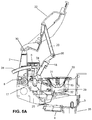
- Fig. 5A shows a side sectional view of the mechanism of Fig. 4 .
- the cover (22) pivots open and closed on hinge pins (30) on each side that attach the cover (22) to a link base (2).
- the link base (2) is mounted on the lower housing (3) that provides a pedestal for the cover (22).
- the cover (22) is coupled with a link bar (20) to the ram frame (18) that also moves downward when the cover (22) is closed.
- Fig. 5A shows a cold capsule (31) seated in cavity (29). In this case, when the cover (22) is closed by a user, the link bar (20a) forces the ram frame (18) down on to the cold capsule (31). The cold capsule (31) moves downward and rotates against a protrusion (shown in Fig. 2A ), and is forced open.
- the cavity (29) is not simply cylindrical, but has a lower cylindrical part (32) and a tapered, conical upper part (33).
- the upper part (33) is adapted to receive and hold a cold capsule of the type previously discussed.
- the lower substantially cylindrical part (32) is adapted to receive and hold a hot capsule, which being of smaller diameter and different shape from the cold capsule, seats lower than a cold capsule.
- the bottom of the cavity (29) has a vertical needle (25) used to puncture the bottom of a hot capsule when the machine cover (22) is closed.
- FIG. 5A the injection needle (24) can be seen attached to an injection hose (28) in a horizontal or rest position. This is its starting or rest position where the injection needle arm (9) is in the vertical position.
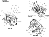
- Fig. 5B is a side sectional view of the mechanism with a hot capsule inserted and the injection needle (24) half-way deployed.
- Fig. 5C is a perspective view of the mechanism with the injection needle (24) fully deployed and sealed against the top of the hot capsule.
- the injection arm (9) can be seen attached with a first drive link (10) and second drive link (11) through a pivot (34).
- An injection arm (9) is attached to a partial gear (17).
- the injection needle (24) rotates continuously from the rest position shown in Fig. 5A to a final position shown in Fig. 5C where it has punctured the hot capsule.
- Fig. 5B shows the injection needle (24) half-way through the rotation cycle.
- the partial gear (17) is driven with a smaller drive gear (8) that is coupled to a drive motor (not shown). As the motor rotates the drive gear (8), the partial gear (17) makes a partial rotation causing the injection needle arm (9) to move from the vertical position to a horizontal position over the hot capsule (27) causing the injection needle (24) to puncture the hot capsule top.
- Fig. 5C shows a top-side perspective view of the mechanism with the injection needle (24) fully deployed.
- the injection needle (24) has punctured the hot capsule, and hot liquid can be injected into the capsule through the injection hose (28).
- the mechanism that drives the injection needle includes a link base (2) and an armature mount (6) which provide support for the injection needle rotation sub-system.
- the first drive link (10) can be seen attached to the partial gear (17).
- the injection arm (9) is attached to the partial gear (17) (shown in Fig. 5B ). It can be seen in Fig. 5C that the partial gear (17) and hence the drive gear (shown in Fig. 5B ) are located laterally at the approximate center of the assembly.
- Fig. 5D a bottom perspective view of the mechanism can be seen with the cover (22) in the closed configuration.
- the lower housing (3) is attached to the upper housing (1), and the cover (22) pivots between an open and closed position.
- the closed position is shown in Fig. 5D .
- a hot spout (4) and a cold beverage orifice (35) can be seen.
- a motor mount (13) that holds the drive motor (not shown).
- the drive motor directly drives the drive gear (8) which is coupled to the partial gear (shown in Fig. 5C ).
- a mounting bracket (7) is used to mount the drive gear (8).
- the present invention can dispense both cold and hot beverages.
- the sequential process employed for both situations will now be examined step-by-step.
- the dispensing mechanism can seen in section in a static or resting configuration with the cover (22) open.
- the cover (22) is coupled to the ram frame (18) through a link bar (20)
- the ram frame (18) is fully raised.
- a cold capsule (31) of the type previously described is shown inserted into the dispensing cavity (29).
- the cold beverage capsule (31) has a rim that allows it to seat high in the cavity (29) which in the partially conical upper region (33).
- Fig. 6 shows the mechanism as the user is closing the cover (22).
- the cover's downward travel has caused the ram frame (18) to pivot downward onto the capsule (31) through the action of the two link bar (20) and the pivot (36) capturing the capsule.
- Fig. 7 shows the mechanism as the user finally pushes the cover (22) totally closed.
- This final push causes the cold capsule (31) to pry open along a scored seam on its rim or directly below its rim because the outer edge of the capsule rim abuts a protrusion (shown in Fig. 2A ) as the capsule body is pressed downward as has been previously described.
- the pod frame (16) is a rotating member that pries the cold capsule into an open configuration.
- Fig. 8 shows the mechanism after the cover (22) is closed and the cold capsule (31) has been torn open.
- the entire pod frame (16) along with the ram frame (18) rotates forward to prepare for dispensing the cold beverage.
- a motor typically a stepper motor, and other drive gears (not shown) rotate the cold capsule (31) into an emptying position.
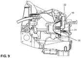
- Fig. 9 shows the mechanism after the pod frame (16) has completely rotated the cold capsule.
- This is the cold beverage dispense configuration where contents of the cold capsule (31) are dispensed when a stream of cold liquid such as water is injected into the body of the cold capsule (31).
- the ready-to-drink cold beverage dispenses out of the bottom of the assembly through an orifice directly into a cup through a cold drink exit orifice (35).
- the system rotates back to the original neutral position.
- the user can dispose of the spent cold capsule (31) upon opening the cover (22).
- an additional mechanism forces the spent cold capsule (31) into a disposal area.
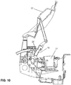
- Fig. 10 shows a side sectional view of the mechanism with the cover (22) completely open and a hot beverage capsule (27) inserted into the cavity (29) Since the hot capsule (27) is more nearly cylindrical than the cold capsule (although slightly conical), its rim does not extend out as far as the rim on a cold capsule, and it tends to seat lower in the cavity (29). There is a bottom needle (25) under the hot capsule (27) that will puncture the bottom of the hot capsule when the cover (22) is fully closed. The injection needle (24) is in a neutral or rest position, and the ram frame (18) is raised.
- Fig. 11 shows the mechanism as the user closes the cover (22).
- the ram frame (18) has rotated downward in response to the linkage (20) and rests on top of the hot capsule (27) capturing it.
- the hot capsule (27) is sitting on the bottom needle (25), but the bottom needle has not yet pierced the capsule.
- Fig. 12 shows the mechanism with the cover (22) completely closed.
- the force of closing the cover has caused the ram frame (18) to press the capsule (27) down onto the bottom needle (25) forcing the bottom needle to puncture the bottom of the capsule (27).
- the system is ready to brew the hot beverage.
- Fig. 13 shows the next step as the drive motor (not shown) begins to turn the drive gear (8) which turns the partial gear (17). This causes the injection arm (9) to pivot forward bringing the injection needle (24) toward the top of the hot capsule (27).
- Fig. 14 shows the injection needle (24) piercing through the top of the hot capsule (27) as the injection arm has reached its lowest position.
- the drive gear (8) and partial gear (17) have reached the end of their allowed rotation and have stopped.
- Hot liquid may now be injected under pressure into the hot capsule (27) through the injection needle (24).
- An injection needle seal (23) seals the injection needle (24) to the top of the hot capsule (27) preventing leakage during the injection.
- the hot drink now brews or mixes. It is forced out through the hole in the bottom of the hot capsule and is dispensed into a cup through a hot spout (4) (shown in Fig. 5D and Fig. 20 ).
- the user After the hot beverage is dispensed, the user (or the next user) can dispose of the spent hot capsule (24) after opening the cover (22).
- Figs. 15 , 16 , 17 , 18 , 19 and 20 show the outside of the hot/cold dispense mechanism from each primary direction.
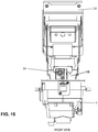
- Fig. 15 shows a front view.
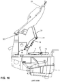
- Fig. 16 shows a left view.
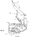
- Fig. 17 shows a right view.
- Fig. 18 shows a rear view.
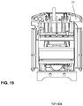
- Fig. 19 shows a top view.
- Fig. 20 shows a bottom view.
- Fig. 15 a front view of the hot/cold mechanism is seen.
- the cover (22), ram frame (18) and injection needle (24) are visible.
- the cover (22) is shown in the open position.
- Fig. 16 shows a left view of the mechanism.
- the cover (22), link (20)and pivot (34) can be seen.
- the pin hinge (30) allows the cover (22) to pivot.
- the opening frame (5) and the opening pod frame (16) are also visible.
- Fig. 17 shows a right view of the mechanism. Again, the cover (22) and link (20) can be seen.
- a special partial gear assembly (38) driven with a different motor causes the pod frame (16) to rotate as has been discussed in order to allow the contents of a cold capsule to be dispensed.
- Fig. 18 shows a rear view of the mechanism.
- the cover (22) is seen from the back side and closes downward and away from the point of view.
- the injection needle drive gear (8) can be seen through a slot in the rear of the lower housing.
- Fig. 19 shows a top view that mostly includes the cover (22), while Fig. 20 shows a bottom view.
- the hot spout (4) and the cold orifice (35) can be seen.
- the drive motor mount (13) the injection needle drive gear (8) and the partial gear (17).
- the injection hose (28) can be seen exiting the top rear of the housing.
- Figs. 21A-21C show three perspective views of the mechanism in three different positions. Most of the features previously described can be seen. Of particular interest is the pod frame (16) that rotates to open the cold capsule while the ram frame (18) acts to restrain the it. A lower pouring frame holds the cold drink parts. This lower pouring frame is driven by the lower gear (38) to rotate forward to allow the cold beverage to dispense. The upper pouring frame (19) rotates to seat either type of capsule.
- Particular embodiments of the present invention can be equipped with a sensor that determines whether a cold capsule or a hot capsule has been inserted into the mechanism (or that anything has been inserted).
- This sensor can be coupled to the controller so that if the user has inserted the wrong type of capsule for his or her selection, the machine can display an error message and not actually dispense the beverage or cause deployment of the injection needle onto a cold capsule. In the case of an error, the user can be given a chance to either remove mis-inserted capsule and discard it, or to correct his or her selection to match the inserted capsule. Because when the cover (22) is completely closed, a cold capsule has been torn open, or the bottom needle has penetrated a hot capsule, it is not possible to remove a mis-inserted capsule and use it later. If it is removed, it should be discarded.
- the hot dispensing is configured so that the top of the hot capsule is punctured by the inlet needle before the bottom is punctured by the outlet needle.
- FIG. 22 a cross-section of this embodiment may be seen.
- the hot capsule (27) is seated in cavity (29) in a manner similar to previously-described embodiments.
- the capsule (27) sits on a carrier (50) that is springloaded upward by a carrier spring (51).
- the cover (22) is open.
- An outlet needle (25) is located under the capsule (27).
- An inlet injection needle (24) is shown in a retracted position away from the capsule (27).
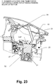
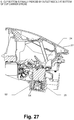
- Figs. 23-27 show the sequence of preparing and dispensing a hot drink.
- the cover (22) has been closed.
- a ram frame (18) forces the cup carrier (50) and capsule (27) partially downward against the carrier spring (51).
- the outlet needle (25) remains below the capsule (27) and does not puncture the capsule.
- a motor-driven arm (11) begins to rotate the inlet injection needle (24) toward the top of the capsule, while the outlet needle (25) continues to remain below the capsule (27).
- the arm (11) is driven by gears which are coupled to a motor.
- the inlet injection needle (24) punctures the top of the capsule (27) as the arm (11) reaches an approximately horizontal position.
- the outlet needle (25) is still below the bottom of the capsule (27) and has not yet punctured it.
- the motor-driven arm (11) begins to force the capsule (27) further downward against the spring and onto the outlet needle (25).
- the plastic capsule bottom (54) can deflect slightly before piercing occurs.
- the capsule bottom (54) is punctured by the outlet needle (25) at the bottom of the capsule carrier stroke.
- Hot liquid can then be infused into the capsule through the inlet injection needle under pressure to produce the hot drink.
- the finished hot drink can be conveyed out of the bottom of the capsule though the outlet needle (25) and dispensed to a cup through a hot orifice as in other embodiments.
- the motor-driven arm (11) After the dispensing is complete, the motor-driven arm (11) returns to the vertical position shown in Fig. 22 .
- the capsule carrier is forced upward by the carrier spring (51) to the position shown in Fig. 23 .
- the spent capsule is further forced upward by the carrier spring (51) to the position shown in Fig. 22 where it can be manually or automatically removed.
Landscapes
- Engineering & Computer Science (AREA)
- Food Science & Technology (AREA)
- Mechanical Engineering (AREA)
- Apparatus For Making Beverages (AREA)
- Devices For Dispensing Beverages (AREA)
Description
- The present invention relates generally to beverage dispensing systems and more particularly to a complete beverage dispensing system that can dispense both cold and hot drinks.
- There are a number of devices and techniques for dispensing a beverage such as, for example, a cup of coffee or tea from a capsule. In one approach a disposable container fits on top of a cup and has a compartment for receiving a beverage extract such as coffee with a large reservoir on top into which a person must pour boiling water. These devices can be disposable but expensive, the coffee is exposed to the air where it can easily get stale or contaminated, and they are not generally suitable for automatic coffee making or other beverage machines. Because the flow rate of beverage is generally slow, these devices are typically large relative to the volume of beverage dispensed. Also, these devices can be designed to be used upright and only the bottom area is available for filtration flow and this contributes to the slowness of the filtration process. In one construction, a filter is provided in a sealed receptacle and a support member is included intermediate the receptacle and filter which functions to support the filter. When the filter is wetted, it sags and conforms with the support member which has a hole in it to release the filtered beverage but otherwise blocks the output of the filter. Such a filter design used in an application where water is injected under pressure would provide low flow rates.
- There are several known companies offering proprietary capsule based machines in the coffee and tea space, including Nestle's Nespresso and Special T, Green Mountain Coffee Roaster's Keurig, Starbucks Verismo, Kraft's Tassimo, Sara Lee's Senseo, Nescafe's Dolce Gusto, Illy, Lavazza's Blue and Britta Yource. Mars Flavia and Esio are machines utilizing a pouch-style single use dispensing system. Additionally, there are several known companies operating single serving drink machines in the commercial environment, including PHSI's Interpure, Waterlogic's Innowave, Vertex's Charm, Keurig, Nestle and Mars Flavia.
- Currently, there are other machines attempting to commercialize a similar capsule/pod based single-serve point of use cold beverage system. For example, Omnifrio, acquired by Primo Water, uses a puncture mechanism, which punctures the top and bottom of the capsule allowing a syrup concentrate to drain out. Bevyz uses a pressure mechanism to pop open the capsule to enable a mixing process. The Esio Hot & Cold Beverage System uses a syrup pouch system and pumps drink mix out of the pouch to mix it with water outside of the packet. Yource by Brita uses a capsule based machine.
- When cold drinks are dispensed in a system in which the beverage is prepared by mixing cold fluid, usually water, with a powder instead of a liquid concentrate, one significant challenge is that the powder will not dissolve effectively during the mixing process. This can lead to poor quality output from the beverage system and unsightly and possibly unhealthful residue in the machine itself. Improved systems for providing a hot, cold, ambient temperature, carbonated, still mixed beverage designed to enable the effective mixture of the powder with the liquid during dispensing providing for little or no residue, contamination, or cross contamination between beverages are described in
U.S. Application No. 13/293,043 ,U.S. Provisional Application No. 61/411,786 International Application No. PCT/US2011/060050 , -
WO 2013/119497 is the prior art closest to the invention and discloses a beverage dispensing device adapted to dispense both hot and cold beverages using one single beverage preparation mechanism and one single exit orifice. - In addition, there is no machine or system in the prior art that can dispense both cold and hot drinks. It would be highly advantageous to have a single beverage dispensing machine that can receive either a hot drink or a cold drink capsule, process the capsule and dispense the desired hot or cold drink. While the hot and cold drink capsules can be identical in shape and size, it is advantageous to have them of different shapes and sizes. Maintaining the familiar hot drink capsule (such as the well-known coffee capsule used by Green Mountain Keurig) readily identifies it from the cold drink capsule used by LaVit LLC. This prevents mistakes by the user and makes it easier for the system to identify whether a cold drink or a hot drink is desired.
- The present invention comprises a complete hot and cold beverage dispensing device comprising the features of
claim 1. It is a machine with a compartment adapted to receive a drink mix capsule and a control panel that can display messages to a customer and allow the customer to choose drink options. The present invention also comprises a beverage preparation mechanism or sub-system to totally control the mechanical portion of hot and cold beverage preparation. - To dispense a beverage, a user approaches the machine, places a cold drink capsule or a hot drink capsule into the compartment, closes the lid, and selects the type of drink on the control panel (or the selection may be made automatically by the system based on the type of capsule inserted).
- If the selection and capsule represent a cold drink, the machine opens the capsule when the machine cover is closed. An upper nozzle injects a small amount of cold liquid to mix with and dissolve (or dilute) the contents. A second nozzle begins to fill the vessel (cup) below an exit orifice. Simultaneously, an internal mechanism rotates the capsule approximately ninety degrees to empty the contents of the capsule into the vessel. The cold drink capsules can contain a powder or a liquid which is mixed into the filtered water to produce the cold beverage. The drinks can be "house formulas" or common mass market branded beverages licensed from the manufacturers.
- The cold drink capsule is opened by cracking and peeling. This method of accessing the capsule offers an effective and efficient way to prepare and deliver the beverage. A mechanical device is adapted to crack the capsule along a crease punched into the capsule below the top cover of the capsule. The mechanical device peels open the capsule along the cracked crease typically when a user closes the lid. For example, a slight crease could be included in a lip of the capsule or directly below it that can be used to break the seal and allow the cover to then be peeled or pried back. As stated, when the cover is peeled back (e.g., tearing open the capsule) the drink is mixed with a mixing stream of liquid, which in many embodiments will be water, either cold or hot, sparkling or still.
- If the selection and capsule represent a hot drink, the capsule is punctured by a needle on the bottom by closing the lid. Closing the lid of the machine forces the hot drink capsule down on the needle. An injection needle arm rotates a needle into position that penetrates the lid of the capsule. A hot liquid is injected into the hot capsule to brew or mix the hot drink. The hot drink is forced out of the hole in its bottom by pressure via a hot drink spout into a cup. The hot drink capsule can contain powder, grind (such as ground coffee) or a liquid which is brewed or mixed with injected hot liquid such as hot filtered water.
- A purpose of the present invention is to offer a compelling alternative to bottled water and other water based ready-to-drink (RTD) beverages. The invention is meant to offer a convenient, reliable, and cost effective Point of Use solution to the consumer's hydration and beverage needs, both hot and cold. The invention is a single-serve beverage system that can produce unlimited chilled filtered water as well as single serve unique beverages through a cold capsule-based system. The present invention can dispense carbonated, flavored, enhanced, ultra purified filtered waters and flavors, hot coffee, hot and cold tea, hot chocolate and numerous other beverages both hot and cold..
- Attention is now directed toward several drawings that illustrate features of the present invention:
-
Fig. 1 shows an embodiment of the complete hot and cold beverage dispensing system. -
Figs. 2A and 2B show one embodiment of a typical cold capsule. -
Fig. 3 shows a schematic diagram of the controller and other driven components of the system. -
Fig. 4 shows a perspective view of an embodiment of a hot/cold dispensing mechanism. -
Fig. 5A shows a side sectional view of the hot/cold dispensing mechanism in a neutral or starting configuration with a cold capsule inserted. -
Fig. 5B shows a side section view of the hot/cold dispensing mechanism with a hot capsule inserted and the injection needle half-way deployed. -
Fig. 5C shows a perspective view of the mechanism ofFig. 2B with the injection needle fully deployed. -
Fig 5D shows a bottom perspective view of the hot/cold mechanism. -
Fig. 6 shows a side sectional view of the hot/cold mechanism with the cover partly closed. -
Fig. 7 . shows a side sectional view of the hot/cold mechanism with the cover completely closed. -
Fig. 8 shows a side sectional view of the hot/cold mechanism with the cover completely closed as the pouring frame begins to rotate the cold beverage capsule. -
Fig. 9 shows a side sectional view of the hot/cold mechanism with the cover completely closed with the pouring frame at the maximum rotated position. -
Fig. 10 shows a side sectional view of the hot/cold mechanism with the cover open in the neutral configuration with a hot beverage capsule or k-cup inserted. -
Fig. 11 shows a side sectional view of the hot/cold mechanism with the cover partially closed and the hot capsule sitting on the bottom needle. -
Fig. 12 shows a side sectional view of the hot/cold mechanism with the cover totally closed so that the bottom needle has punctured the bottom of the hot capsule. -
Fig. 13 shows a side sectional view of the hot/cold mechanism with the cover totally closed while the injection needle rotates over the hot capsule. -
Fig. 14 shows a side sectional view of the hot/cold mechanism with the cover totally closed and the injection needle piercing the top of the hot capsule. -
Fig. 15 shows a front view of the hot/cold mechanism. -
Fig. 16 shows a left view of the hot/cold mechanism. -
Fig. 17 shows a right view of the hot/cold mechanism. -
Fig. 18 shows a rear view of the hot/cold mechanism. -
Fig. 19 shows a top view of the hot/cold mechanism. -
Fig. 20 shows a bottom view of the hot/cold mechanism. -
Figs. 21A, 21B and 21C show three isometric view of the hot/cold mechanism in different positions. -
Fig. 22 shows a cross-section of an alternate embodiment of the present invention where the top of a hot capsule is pierced before the bottom. -
Figs. 23-27 show the sequence of events during the dispensing of a hot beverage with the embodiment ofFig. 22 . - Several drawings and illustrations have been presented to aid in understanding the present invention. The scope of the present invention is not limited to what is shown in the figures.
- The present invention comprises a complete hot and cold beverage dispensing system. It also comprises a beverage preparation mechanism or sub-system that can be inserted and removed from a housing to totally control the mechanical portion of hot and cold beverage preparation.
- An embodiment of a total beverage dispensing machine or system is shown in
Fig. 1 and includes an outer housing (200) with a cover (201) containing a cold and hot water or other liquid supply, a controller that controls all aspects of beverage preparation and dispensing and the beverage preparation mechanism that actually dispenses the drink. The controller is in electrical communication with one or more user control panels (201) where messages can be displayed to the user, and the user can select various beverages. Selections may also be made with buttons (203). In some embodiments, selection of a cold or hot drink is made solely on the basis of what type of capsule is inserted. Typical selections can be cold drinks such as fruit drinks, lemonade, other flavored cold drinks and the like, while hot beverages can include coffee, tea, hot chocolate and the like. The processor can be a microcontroller known in the art, a microprocessor, or any other type of processor or computer configured to store and execute stored instructions. The controller typically includes on-board and external memory. In some embodiments, the controller may have communication capability and be able to communicate status and receive commands over a network like the Internet. - Both hot and cold beverages are supplied in sealed capsules. Cold beverage capsules (or simply cold capsules) are typically roughly diamond-shaped cups with a rim that seats a sealed lid. The cups can contain either powder or liquid cold drink mixes. Each cold capsule typically has a groove, score or indentation either on the rim or directly below the rim. When the capsule is captured by the machine and pressed downward by the user closing the machine lid, the cold capsule can be opened by allowing the rim to encounter a protrusion on one of its ends. The upward force of the protrusion against the rim as the capsule rotates or moves downward causes part of the rim to tear open along the groove providing an opening where cold liquid can be injected into the capsule causing the mixed cold drink to exit the capsule and fill a cup below the mechanism. A typical embodiment of cold capsules are similar to capsules supplied by LaVit LLC of New York for their cold beverage dispensing systems (see pending
U.S patent application no. 13/293,043 published as 2012/0231126 by some of the same inventors as the present invention).Fig. 2 shows an embodiment of a typical cold capsule. - The hot capsules are similar to the familiar cups supplied by for coffee dispensing by several vendors. For the present invention, the hot capsules can contain other products besides just coffee including tea or hot chocolate for example, or any other hot drink.
- Returning to
Fig. 1 , a view of an embodiment of the system of the present invention can be seen. The housing (200) includes a base (300) and an access lid or cover (201) that allows insertion of a cold or hot capsule. A control panel (201) is also mounted on the housing (200) that allows a user to select and command preparation of a beverage. The housing (200) contains all necessary components including plumbing, liquid heating, control and sensing as well as a hot/cold beverage dispensing module or mechanism. -
Fig. 2A shows a typical cold capsule (302) with a rim (305) and lid (303). A protrusion (301) pries the rim (305) open when the capsule is forced to rotate downward while being captured with a fixed member (304).Fig. 2B shows the pried open cold capsule (302). WhileFig. 2B shows the capsule being opened at both ends, a preferred way of opening the capsule is to open it only at one end. Either opening technique is within the scope of the present invention. -
Fig. 3 shows schematically the controller (203) which can be solid state controller chip known in the art. The controller (203) is electrically coupled to the control panel (202) which can be a touch panel, LCD panel or any other control panel of any type. The controller (203) is a processor that executes stored instructions that, in addition to reading and writing the control panel (202)
also controls one or more drive motors (204) that are typically part of the mechanical drink preparation module (205). The controller (203) can command the drink preparation module (205) to either prepare and dispense a cold beverage or to prepare and dispense a hot beverage depending upon the user selection. The control panel (202) can display a message to insert the proper capsule in the preparation mechanism and to close the cover. The controller (203) can also receive an instruction about the size of the cup placed under the device and hence provide the correct amount of cold or hot fluid. In some embodiments, the controller (203) receives sensor or camera information as to what type of capsule has been inserted and proceeds to prepare a cold or hot drink. In the case of a camera, the camera can read a label or barcode on the capsule. - Usually, the cold or hot fluid is filtered water; however, it does not have to be water. Other fluids may be used with some drinks. In particular, for some cold drinks, the fluid can be carbonated water. Any fluid is within the scope of the present invention. The controller (203) can also control various pumps (206), heaters (207), and valves (208). In addition, it can read the temperature of the hot injection liquid with a temperature sensor (209). The controller (203) temperature sensor (209) and heater(s) (207) can operate in a closed-loop configuration. Finally, in some embodiments of the present invention, the controller (213) can read a sensor or camera (210) located near the capsule insertion point to determine whether a cold capsule or hot capsule (or any capsule) has been inserted. The sensor (210) may include two or more sensors, one to determine if anything at all has been inserted, and another to determine whether a cold or hot capsule has been inserted. There may be a camera (212) to read a label or barcode on the capsule . These may be infrared LED sensors or any other type of sensor. Further sensors (211) can optionally determine whether the cover is open or closed (seated) and the position of rotating members in the hot/cold dispensing module. If the cover is in the wrong position, the controller (203) can place an error message on the control panel (201).
- The actual preparation and dispensing of the cold or hot beverage is handled by an insertable hot/cold dispensing mechanism or module that will now be described in detail.
- The present invention deploys an insertable beverage dispensing module or mechanism that can dispense cold beverages using the sealed capsule previously described and can dispense hot beverages using capsules similar to standard capsules known in the art for dispensing coffee. The cold beverage capsules may contain a powder or liquid mix for any cold drink; the hot capsules may contain a powder mix for any hot drink including coffee, tea and hot chocolate, or any other hot drink.
- The present invention handles both cold and hot beverages by using an unique mechanism adapted to manipulate both types of capsules. When a cold drink is desired, the user inserts a cold drink capsule into the mechanism and closes the machine lid. The shape of the cold drink capsule, and the manner in which it is seated in the mechanism causes it to be pried open when the lid is closed by being pushed downward against a protruding part as previously described. Cold liquid such as water or other cold liquid can then be injected into the capsule mixing and forcing the contents out and producing a cold drink.
- When a hot drink capsule is inserted in the mechanism, closing the machine lid does not open this type of capsule since it is shaped differently. However, it does press the hot capsule down on a bottom puncture needle making a hole in the bottom of the hot capsule. An injection needle arm then rotates from a vertical rest position to a horizontal position over the hot drink capsule causing an injection needle to puncture the top of the capsule. Hot liquid can then be forced or injected into the hot drink capsule under pressure to produce a hot drink. The brewed or mixed hot drink is forced out of the bottom hole or bottom needle to a hot spout from where it flows into a cup.
- Turning to
Fig. 4 , a perspective view of an embodiment of a hot/cold dispensing mechanism can be seen. This mechanism, or head, fits into the drink dispensing machine previously described in place of a cold-drink-only mechanism. The mechanism ofFig. 4 includes an upper housing (1), and a lower housing (3) that are joined to form a single housing. A cover or lid (22) is attached so that it can pivot closed or open on rear pins or hinges. The cover (22) is typically biased closed, but can be easily opened and closed by hand. - The mechanism includes a vertical, substantially cylindrical cavity (29) in its center, that when the cover (22) open, is configured to receive and hold either a cold drink capsule or a hot drink capsule. A small protruding lip or frame (5) allows the capsule to seat snugly, but removably in the cavity (29). The lip (5) also prevents insertion of either type of capsule upside-down. A hot drink capsule is typically taller than a cold drink capsule. It thus sits lower in the cavity (29). This provides a way to identify the difference between the two types of capsules with a sensor, camera or other technique. Also, capsules may have bar codes or other readable indicia indicating what type of capsule they are and what type of drink they contain.
- The cover (22) cooperates with the upper housing (1) and is coupled with a pair of links (20) to a ram frame (18) which also pivots downward and is used to force cold drink capsules open in order to open them, and to force hot drink capsules down onto a bottom puncture needle..
-
Fig. 5A shows a side sectional view of the mechanism ofFig. 4 . The cover (22) pivots open and closed on hinge pins (30) on each side that attach the cover (22) to a link base (2). The link base (2) is mounted on the lower housing (3) that provides a pedestal for the cover (22). The cover (22) is coupled with a link bar (20) to the ram frame (18) that also moves downward when the cover (22) is closed.Fig. 5A shows a cold capsule (31) seated in cavity (29). In this case, when the cover (22) is closed by a user, the link bar (20a) forces the ram frame (18) down on to the cold capsule (31). The cold capsule (31) moves downward and rotates against a protrusion (shown inFig. 2A ), and is forced open. - It can be seen in
Fig. 5A , that the cavity (29) is not simply cylindrical, but has a lower cylindrical part (32) and a tapered, conical upper part (33). The upper part (33) is adapted to receive and hold a cold capsule of the type previously discussed. The lower substantially cylindrical part (32) is adapted to receive and hold a hot capsule, which being of smaller diameter and different shape from the cold capsule, seats lower than a cold capsule. The bottom of the cavity (29) has a vertical needle (25) used to puncture the bottom of a hot capsule when the machine cover (22) is closed. - When a hot capsule is used, after the cover (22) is closed and the bottom of the hot capsule has been punctured, an injection needle arm rotates from a stationary vertical position to a horizontal position over the hot capsule which causes an injection needle (24) to punctures the top of the hot capsule. This can be seen in
Figs. 5B-5C . InFig. 5A , the injection needle (24) can be seen attached to an injection hose (28) in a horizontal or rest position. This is its starting or rest position where the injection needle arm (9) is in the vertical position.Fig. 5B is a side sectional view of the mechanism with a hot capsule inserted and the injection needle (24) half-way deployed.Fig. 5C is a perspective view of the mechanism with the injection needle (24) fully deployed and sealed against the top of the hot capsule. - Turning to
Fig. 5B , the injection arm (9) can be seen attached with a first drive link (10) and second drive link (11) through a pivot (34). An injection arm (9) is attached to a partial gear (17). When the partial gear (17) is caused to rotate through an angle, the injection needle (24) rotates continuously from the rest position shown inFig. 5A to a final position shown inFig. 5C where it has punctured the hot capsule.Fig. 5B shows the injection needle (24) half-way through the rotation cycle. The partial gear (17) is driven with a smaller drive gear (8) that is coupled to a drive motor (not shown). As the motor rotates the drive gear (8), the partial gear (17) makes a partial rotation causing the injection needle arm (9) to move from the vertical position to a horizontal position over the hot capsule (27) causing the injection needle (24) to puncture the hot capsule top. -
Fig. 5C shows a top-side perspective view of the mechanism with the injection needle (24) fully deployed. In this configuration, the injection needle (24) has punctured the hot capsule, and hot liquid can be injected into the capsule through the injection hose (28). The mechanism that drives the injection needle includes a link base (2) and an armature mount (6) which provide support for the injection needle rotation sub-system. The first drive link (10) can be seen attached to the partial gear (17). The injection arm (9) is attached to the partial gear (17) (shown inFig. 5B ). It can be seen inFig. 5C that the partial gear (17) and hence the drive gear (shown inFig. 5B ) are located laterally at the approximate center of the assembly. - Turning to
Fig. 5D , a bottom perspective view of the mechanism can be seen with the cover (22) in the closed configuration. The lower housing (3) is attached to the upper housing (1), and the cover (22) pivots between an open and closed position. The closed position is shown inFig. 5D . On the bottom of the assembly, a hot spout (4) and a cold beverage orifice (35) can be seen. At the lower back of the assembly, there is a motor mount (13) that holds the drive motor (not shown). The drive motor directly drives the drive gear (8) which is coupled to the partial gear (shown inFig. 5C ). A mounting bracket (7) is used to mount the drive gear (8). - As previously stated, the present invention can dispense both cold and hot beverages. The sequential process employed for both situations will now be examined step-by-step.
- Returning to
Fig. 5A , the dispensing mechanism can seen in section in a static or resting configuration with the cover (22) open. The cover (22) is coupled to the ram frame (18) through a link bar (20) The ram frame (18) is fully raised. A cold capsule (31) of the type previously described is shown inserted into the dispensing cavity (29). The cold beverage capsule (31) has a rim that allows it to seat high in the cavity (29) which in the partially conical upper region (33). -
Fig. 6 shows the mechanism as the user is closing the cover (22). The cover's downward travel has caused the ram frame (18) to pivot downward onto the capsule (31) through the action of the two link bar (20) and the pivot (36) capturing the capsule. -
Fig. 7 shows the mechanism as the user finally pushes the cover (22) totally closed. This final push causes the cold capsule (31) to pry open along a scored seam on its rim or directly below its rim because the outer edge of the capsule rim abuts a protrusion (shown inFig. 2A ) as the capsule body is pressed downward as has been previously described. The pod frame (16) is a rotating member that pries the cold capsule into an open configuration. -
Fig. 8 shows the mechanism after the cover (22) is closed and the cold capsule (31) has been torn open. The entire pod frame (16) along with the ram frame (18) rotates forward to prepare for dispensing the cold beverage. A motor, typically a stepper motor, and other drive gears (not shown) rotate the cold capsule (31) into an emptying position. -
Fig. 9 shows the mechanism after the pod frame (16) has completely rotated the cold capsule. This is the cold beverage dispense configuration where contents of the cold capsule (31) are dispensed when a stream of cold liquid such as water is injected into the body of the cold capsule (31). The ready-to-drink cold beverage dispenses out of the bottom of the assembly through an orifice directly into a cup through a cold drink exit orifice (35). - After the cold beverage is dispensed, the system rotates back to the original neutral position. The user can dispose of the spent cold capsule (31) upon opening the cover (22). In some embodiments, an additional mechanism (not shown) forces the spent cold capsule (31) into a disposal area.
-
Fig. 10 shows a side sectional view of the mechanism with the cover (22) completely open and a hot beverage capsule (27) inserted into the cavity (29) Since the hot capsule (27) is more nearly cylindrical than the cold capsule (although slightly conical), its rim does not extend out as far as the rim on a cold capsule, and it tends to seat lower in the cavity (29). There is a bottom needle (25) under the hot capsule (27) that will puncture the bottom of the hot capsule when the cover (22) is fully closed. The injection needle (24) is in a neutral or rest position, and the ram frame (18) is raised. -
Fig. 11 shows the mechanism as the user closes the cover (22). The ram frame (18) has rotated downward in response to the linkage (20) and rests on top of the hot capsule (27) capturing it. The hot capsule (27) is sitting on the bottom needle (25), but the bottom needle has not yet pierced the capsule. -
Fig. 12 shows the mechanism with the cover (22) completely closed. The force of closing the cover has caused the ram frame (18) to press the capsule (27) down onto the bottom needle (25) forcing the bottom needle to puncture the bottom of the capsule (27). The system is ready to brew the hot beverage. -
Fig. 13 shows the next step as the drive motor (not shown) begins to turn the drive gear (8) which turns the partial gear (17). This causes the injection arm (9) to pivot forward bringing the injection needle (24) toward the top of the hot capsule (27). -
Fig. 14 shows the injection needle (24) piercing through the top of the hot capsule (27) as the injection arm has reached its lowest position. The drive gear (8) and partial gear (17) have reached the end of their allowed rotation and have stopped. Hot liquid may now be injected under pressure into the hot capsule (27) through the injection needle (24). An injection needle seal (23) seals the injection needle (24) to the top of the hot capsule (27) preventing leakage during the injection. The hot drink now brews or mixes. It is forced out through the hole in the bottom of the hot capsule and is dispensed into a cup through a hot spout (4) (shown inFig. 5D andFig. 20 ). - After the hot beverage is dispensed, the user (or the next user) can dispose of the spent hot capsule (24) after opening the cover (22).
-
Figs. 15 ,16 ,17 ,18 ,19 and20 show the outside of the hot/cold dispense mechanism from each primary direction.Fig. 15 shows a front view.Fig. 16 shows a left view.Fig. 17 shows a right view.Fig. 18 shows a rear view.Fig. 19 shows a top view.Fig. 20 shows a bottom view. - Turning to
Fig. 15 , a front view of the hot/cold mechanism is seen. The cover (22), ram frame (18) and injection needle (24) are visible. The cover (22) is shown in the open position. -
Fig. 16 shows a left view of the mechanism. The cover (22), link (20)and pivot (34) can be seen. The pin hinge (30) allows the cover (22) to pivot. The opening frame (5) and the opening pod frame (16) are also visible. To open the cold capsule, or press the hot capsule down on the bottom needle, the opening pod frame (16) rotates from the horizontal position shown inFig. 16 to a vertical position. The rotation is around a pin (37). -
Fig. 17 shows a right view of the mechanism. Again, the cover (22) and link (20) can be seen. A special partial gear assembly (38) driven with a different motor causes the pod frame (16) to rotate as has been discussed in order to allow the contents of a cold capsule to be dispensed. -
Fig. 18 shows a rear view of the mechanism. Here the cover (22) is seen from the back side and closes downward and away from the point of view. The injection needle drive gear (8) can be seen through a slot in the rear of the lower housing. -
Fig. 19 shows a top view that mostly includes the cover (22), whileFig. 20 shows a bottom view. The hot spout (4) and the cold orifice (35) can be seen. Also, in the rear of the unit is the drive motor mount (13), the injection needle drive gear (8) and the partial gear (17). Finally, the injection hose (28) can be seen exiting the top rear of the housing. -
Figs. 21A-21C show three perspective views of the mechanism in three different positions. Most of the features previously described can be seen. Of particular interest is the pod frame (16) that rotates to open the cold capsule while the ram frame (18) acts to restrain the it. A lower pouring frame holds the cold drink parts. This lower pouring frame is driven by the lower gear (38) to rotate forward to allow the cold beverage to dispense. The upper pouring frame (19) rotates to seat either type of capsule. - Particular embodiments of the present invention can be equipped with a sensor that determines whether a cold capsule or a hot capsule has been inserted into the mechanism (or that anything has been inserted). This sensor can be coupled to the controller so that if the user has inserted the wrong type of capsule for his or her selection, the machine can display an error message and not actually dispense the beverage or cause deployment of the injection needle onto a cold capsule. In the case of an error, the user can be given a chance to either remove mis-inserted capsule and discard it, or to correct his or her selection to match the inserted capsule. Because when the cover (22) is completely closed, a cold capsule has been torn open, or the bottom needle has penetrated a hot capsule, it is not possible to remove a mis-inserted capsule and use it later. If it is removed, it should be discarded.
- In a different embodiment of the present invention, the hot dispensing is configured so that the top of the hot capsule is punctured by the inlet needle before the bottom is punctured by the outlet needle.
- Turning to
Fig. 22 , a cross-section of this embodiment may be seen. The hot capsule (27) is seated in cavity (29) in a manner similar to previously-described embodiments. The capsule (27) sits on a carrier (50) that is springloaded upward by a carrier spring (51). The cover (22) is open. An outlet needle (25) is located under the capsule (27). An inlet injection needle (24) is shown in a retracted position away from the capsule (27). -
Figs. 23-27 show the sequence of preparing and dispensing a hot drink. InFig. 23 , the cover (22) has been closed. A ram frame (18) forces the cup carrier (50) and capsule (27) partially downward against the carrier spring (51). The outlet needle (25) remains below the capsule (27) and does not puncture the capsule. - In
Fig. 24 , a motor-driven arm (11) begins to rotate the inlet injection needle (24) toward the top of the capsule, while the outlet needle (25) continues to remain below the capsule (27). The arm (11) is driven by gears which are coupled to a motor. - In
Fig. 25 , the inlet injection needle (24) punctures the top of the capsule (27) as the arm (11) reaches an approximately horizontal position. The outlet needle (25) is still below the bottom of the capsule (27) and has not yet punctured it. - In
Fig. 26 , the motor-driven arm (11) begins to force the capsule (27) further downward against the spring and onto the outlet needle (25). The plastic capsule bottom (54) can deflect slightly before piercing occurs. - In
Fig. 27 , the capsule bottom (54) is punctured by the outlet needle (25) at the bottom of the capsule carrier stroke. Hot liquid can then be infused into the capsule through the inlet injection needle under pressure to produce the hot drink. The finished hot drink can be conveyed out of the bottom of the capsule though the outlet needle (25) and dispensed to a cup through a hot orifice as in other embodiments. - After the dispensing is complete, the motor-driven arm (11) returns to the vertical position shown in
Fig. 22 . The capsule carrier is forced upward by the carrier spring (51) to the position shown inFig. 23 . Finally, as the cover (22) is opened, the spent capsule is further forced upward by the carrier spring (51) to the position shown inFig. 22 where it can be manually or automatically removed.
Claims (15)
- A beverage dispensing device adapted to dispense both hot and cold beverages comprising:a housing (200);a control panel (203) mounted on the housing, the control panel configured to permit selection of a beverage;a controller (203) in said housing, the controller in communication with the control panel;a motor-driven hot/cold drink dispensing module (3) mounted in the housing under control of the controller, the hot/cold drink dispensing mechanism comprising:a chassis (1) containing a carrier (29) adapted to receive and hold either a cold capsule containing a cold beverage mix and a hot capsule containing a hot beverage mix;a cover (22) mounted on the chassis, the cover pivotable between an open position and a closed position;a cold beverage exit orifice (35) on a bottom surface of the chassis;a hot beverage exit orifice (4) also on a bottom surface of the chassis;a cold beverage preparation mechanism (33) cooperating with the cover, the mechanism adapted to open an inserted cold beverage capsule as the cover is closed; the cold beverage preparation mechanism also adapted to rotate the opened cold beverage capsule from a horizontal position to a rotated position allowing an injected stream of cold water to mix and force its contents out through the cold beverage exit orifice;a hot beverage preparation mechanism (32) also cooperating with the cover, the hot beverage preparation mechanism including a capsule carrier configured receive and hold a capsule containing a hot beverage mix, the capsule carrier configured to move downward against a spring as the cover is closed; the mechanism also including an outlet needle attached to the chassis below the capsule bottom; an inlet injection needle attached to a motor-driven arm adapted to puncture the capsule's top when the arm is rotated, wherein after the capsule's top is punctured, the motor-driven arm forces the capsule further downward against the spring causing the outlet needle to puncture the capsule's bottom; the mechanism then injecting hot liquid into the capsule through the inlet injection needle and withdrawing hot beverage through the outlet needle and conveying it to the hot beverage exit orifice.
- The beverage dispensing device of claim 1 wherein the motor-driven arm is coupled to the motor through a plurality of gears.
- The beverage dispensing device of claim I wherein the cold capsule has a rim and is adapted to be cracked open along a groove on or directly under said rim.
- The beverage dispensing device of claim 1 wherein the cold capsule contains a powdered cold drink mix.
- The beverage dispensing device of claim 1 wherein the cold capsule contains a liquid cold drink mix.
- The beverage dispensing device of claim 1 wherein the hot capsule contains a coffee, tea or hot chocolate mix.
- The beverage dispensing device of claim 1 wherein the controller is a micro-controller adapted to execute stored instructions.
- The beverage dispensing device of claim 7 wherein the stored instructions allow a user to select either a cold beverage or a hot beverage via the control panel by causing a cold liquid to be injected into the capsule when a cold beverage is selected or hot liquid to be infused into the capsule when a hot beverage is selected.
- The beverage dispensing device of claim I wherein said cavity has a substantially cylindrical bottom part and a partially conical upper part.
- The beverage dispensing device of claim 1 wherein said cover is link connected to a ram member, the ram member adapted to secure the cold or hot capsule in the cavity and to force the hot capsule downward toward the outlet needle without puncture the capsule's bottom when the cover is closed.
- The beverage dispensing device of claim 10 further comprising a rotating member that opens the cold capsule by rotating the cold capsule along a trajectory where a rim portion of the cold capsule encounters a protrusion attached to the chassis causing the cold capsule rim to pry away from the cold capsule.
- The beverage dispensing device of claim I further comprising a sensor electrically connected to said controller cooperating with said cavity notifying the controller whether a cold capsule or a hot capsule has been inserted into said cavity.
- The beverage dispensing device of claim 12 wherein the sensor is a camera that reads a label on the cold or hot capsule.
- The beverage dispensing device of claim 1 wherein the cold water is carbonated.
- The beverage dispensing device of claim I wherein the cold water is filtered water.
Applications Claiming Priority (3)
| Application Number | Priority Date | Filing Date | Title |
|---|---|---|---|
| US14/536,142 US10080459B2 (en) | 2011-11-09 | 2014-11-07 | Capsule-based system for preparing and dispensing a beverage |
| US14/828,067 US10034570B2 (en) | 2011-11-09 | 2015-08-17 | Capsule based system for preparing and dispensing a beverage |
| PCT/US2015/049743 WO2016073069A1 (en) | 2014-11-07 | 2015-09-11 | Capsule-based system for preparing and dispensing a beverage |
Publications (3)
| Publication Number | Publication Date |
|---|---|
| EP3214976A1 EP3214976A1 (en) | 2017-09-13 |
| EP3214976A4 EP3214976A4 (en) | 2019-01-02 |
| EP3214976B1 true EP3214976B1 (en) | 2021-09-08 |
Family
ID=55347187
Family Applications (1)
| Application Number | Title | Priority Date | Filing Date |
|---|---|---|---|
| EP15856702.4A Active EP3214976B1 (en) | 2014-11-07 | 2015-09-11 | Capsule-based system for preparing and dispensing a beverage |
Country Status (11)
| Country | Link |
|---|---|
| US (1) | US10034570B2 (en) |
| EP (1) | EP3214976B1 (en) |
| JP (1) | JP6687614B2 (en) |
| KR (1) | KR102460735B1 (en) |
| CN (1) | CN107427144A (en) |
| AU (1) | AU2015343718B2 (en) |
| BR (1) | BR112017009532B1 (en) |
| CA (1) | CA2966864C (en) |
| ES (1) | ES2898915T3 (en) |
| MX (1) | MX388019B (en) |
| WO (1) | WO2016073069A1 (en) |
Families Citing this family (55)
| Publication number | Priority date | Publication date | Assignee | Title |
|---|---|---|---|---|
| US10722066B2 (en) * | 2010-12-04 | 2020-07-28 | Adrian Rivera | Windowed single serving brewing material holder |
| US11832755B2 (en) * | 2007-07-13 | 2023-12-05 | Adrian Rivera | Brewing material container for a beverage brewer |
| US10071851B2 (en) | 2010-07-12 | 2018-09-11 | Robert Bao Vu | Apparatus and products for producing beverages, and methods for making and using same |
| LT3023362T (en) * | 2010-07-22 | 2018-04-25 | K-Fee System Gmbh | Portion capsule having an identifier |
| US20150079240A1 (en) * | 2010-11-09 | 2015-03-19 | Gian Matteo Lo Foro | Capsule based system for preparing and dispensing a beverage |
| US10034570B2 (en) | 2011-11-09 | 2018-07-31 | LaVit Technology LLC | Capsule based system for preparing and dispensing a beverage |
| US10080459B2 (en) | 2011-11-09 | 2018-09-25 | La Vit Technology Llc | Capsule-based system for preparing and dispensing a beverage |
| NL2014557B1 (en) * | 2015-03-31 | 2017-01-06 | Bravilor Holding Bv | Beverage preparation device. |
| US9883766B2 (en) * | 2015-11-20 | 2018-02-06 | Pepsico, Inc. | Beverage dispenser systems and methods |
| EP3175749A1 (en) * | 2015-12-01 | 2017-06-07 | Qbo Coffee GmbH | Drink preparation machine for preparing a drink |
| EP3423381B1 (en) | 2016-03-01 | 2022-04-27 | Bartesian Inc. | Beverage machine and capsule for use with the beverage machine |
| US20170252990A1 (en) * | 2016-03-03 | 2017-09-07 | Juicero, Inc. | Juicer cartridge geometry |
| US20170251863A1 (en) * | 2016-03-03 | 2017-09-07 | Juicero, Inc. | Angled juicing system |
| US20170252998A1 (en) * | 2016-03-03 | 2017-09-07 | Juicero, Inc. | Juicer cartridge with flow disruptor |
| US20170253000A1 (en) * | 2016-03-03 | 2017-09-07 | Juicero, Inc. | Juicer with locking mechanism |
| US20170252996A1 (en) * | 2016-03-03 | 2017-09-07 | Juicero, Inc. | Juicer cartridge with secondary flow channel |
| US20170252997A1 (en) * | 2016-03-03 | 2017-09-07 | Juicero, Inc. | Juicer cartridge with sanitary seal |
| US20170252993A1 (en) * | 2016-03-03 | 2017-09-07 | Juicero, Inc. | Juicer cartridge with coupling |
| US20170252995A1 (en) * | 2016-03-03 | 2017-09-07 | Juicero, Inc. | Juicer cartridge with outlet separator |
| US20170252991A1 (en) * | 2016-03-03 | 2017-09-07 | Juicero, Inc. | Juicer with flexible seal |
| US20170252999A1 (en) * | 2016-03-03 | 2017-09-07 | Juicero, Inc. | Juicer with juicer cartridge orientation feature |
| SG11201808980UA (en) * | 2016-04-14 | 2018-11-29 | Meltz Llc | Systems for and methods of controlled liquid food or beverage product creation |
| GB201619695D0 (en) * | 2016-11-22 | 2017-01-04 | Hodges & Drake Design Ltd | Beverage flavouring apparatus |
| US11643269B2 (en) | 2016-12-01 | 2023-05-09 | Bedford Systems, LLC | Container and opening arrangement for beverage production |
| GB2570366B (en) * | 2018-01-26 | 2020-03-18 | Ne Innovations Ltd | Pod and dispensing method |
| CN108209579A (en) * | 2018-03-20 | 2018-06-29 | 无锡鼎加弘思饮品科技有限公司 | A kind of full-automatic beverage dispenser |
| EP4289317A3 (en) * | 2018-03-22 | 2023-12-20 | Bedford Systems LLC | Puncture mechanism for beverage machine |
| USD890569S1 (en) | 2018-06-19 | 2020-07-21 | Bartesian Inc. | Beverage capsule receiving adaptor |
| CN112021941B (en) * | 2019-06-04 | 2022-04-15 | 广东美的生活电器制造有限公司 | Brewing device and beverage machine |
| US12064050B2 (en) * | 2019-06-04 | 2024-08-20 | Guangdong Midea Consumer Electric Manufacturing Co., Ltd. | Beverage capsule, brewing device, and beverage dispenser |
| CN110326968A (en) * | 2019-06-28 | 2019-10-15 | 广东亿龙电器科技有限公司 | Capsule coffee machine |
| CN110367823B (en) * | 2019-07-16 | 2024-08-02 | 深圳市西啡科技有限公司 | Brewing device and beverage machine |
| CN114554915B (en) * | 2019-09-25 | 2025-03-18 | 库里格绿山股份有限公司 | Cartridge stabilizers for beverage machines |
| WO2022084885A1 (en) * | 2020-10-21 | 2022-04-28 | Tooa S.P.A. | Method for the production of ice cream and system executing this method |
| US11805934B1 (en) * | 2020-10-21 | 2023-11-07 | Adrian Rivera | Brewing material lid and container for a beverage brewer |
| CN113180472B (en) * | 2021-05-11 | 2023-06-09 | 深圳市晨北科技有限公司 | Coffee machine cover and capsule coffee machine |
| US20230294912A1 (en) * | 2022-03-16 | 2023-09-21 | Stack Street Coffee LLC | Beverage brewing |
| US12096880B2 (en) | 2022-05-13 | 2024-09-24 | Sharkninja Operating Llc | Flavorant for beverage carbonation system |
| US11751585B1 (en) | 2022-05-13 | 2023-09-12 | Sharkninja Operating Llc | Flavored beverage carbonation system |
| US12213617B2 (en) | 2022-05-13 | 2025-02-04 | Sharkninja Operating Llc | Flavored beverage carbonation process |
| US11647860B1 (en) | 2022-05-13 | 2023-05-16 | Sharkninja Operating Llc | Flavored beverage carbonation system |
| US12539500B2 (en) | 2022-08-31 | 2026-02-03 | Sharkninja Operating Llc | Additive containers |
| US11634314B1 (en) | 2022-11-17 | 2023-04-25 | Sharkninja Operating Llc | Dosing accuracy |
| US11745996B1 (en) | 2022-11-17 | 2023-09-05 | Sharkninja Operating Llc | Ingredient containers for use with beverage dispensers |
| US11738988B1 (en) | 2022-11-17 | 2023-08-29 | Sharkninja Operating Llc | Ingredient container valve control |
| US12084334B2 (en) | 2022-11-17 | 2024-09-10 | Sharkninja Operating Llc | Ingredient container |
| US12103840B2 (en) | 2022-11-17 | 2024-10-01 | Sharkninja Operating Llc | Ingredient container with sealing valve |
| USD1091308S1 (en) | 2022-12-23 | 2025-09-02 | Sharkninja Operating Llc | Ingredient container |
| USD1092208S1 (en) | 2022-12-23 | 2025-09-09 | Sharkninja Operating Llc | Cap of ingredient container |
| US12116257B1 (en) | 2023-03-22 | 2024-10-15 | Sharkninja Operating Llc | Adapter for beverage dispenser |
| US11871867B1 (en) | 2023-03-22 | 2024-01-16 | Sharkninja Operating Llc | Additive container with bottom cover |
| US11925287B1 (en) | 2023-03-22 | 2024-03-12 | Sharkninja Operating Llc | Additive container with inlet tube |
| US12005408B1 (en) | 2023-04-14 | 2024-06-11 | Sharkninja Operating Llc | Mixing funnel |
| EP4727685A1 (en) | 2023-06-16 | 2026-04-22 | SharkNinja Operating LLC | Carbonation chamber |
| USD1132072S1 (en) | 2024-05-31 | 2026-06-30 | Sharkninja Operating Llc | Beverage dispenser |
Family Cites Families (159)
| Publication number | Priority date | Publication date | Assignee | Title |
|---|---|---|---|---|
| US3101870A (en) | 1960-10-12 | 1963-08-27 | Plastomatic Corp | Film sealed container with pouring spout |
| US3295998A (en) | 1962-05-28 | 1967-01-03 | Vendcor Inc | Apparatus for preparing and dispensing hot potables |
| GB1115285A (en) | 1966-03-17 | 1968-05-29 | Bratby & Hinchliffe Ltd | Carbonators |
| US3743520A (en) | 1971-09-03 | 1973-07-03 | J Croner | Compartmented beverage container |
| US4808346A (en) | 1972-07-20 | 1989-02-28 | Strenger & Associates | Carbonated beverage dispensing apparatus and method |
| DE7604691U1 (en) | 1976-02-18 | 1976-07-08 | Bosch Gmbh Robert | Container packing |
| SE423218B (en) | 1977-11-17 | 1982-04-26 | Haustrup Plastic As | ORIGINAL PRESSURE AND RELEASABLE CONTAINER DEVICE |
| US4437499A (en) | 1981-05-11 | 1984-03-20 | Everpure, Inc. | Computer controlled sensor for beverage dispenser |
| US4492295A (en) | 1982-03-05 | 1985-01-08 | Environmental Products Corporation | Automated redemption center for metal containers |
| DE3446093A1 (en) | 1984-12-18 | 1986-06-19 | Klaus A. 2000 Hamburg Sontag | Pouring container |
| US4749580A (en) | 1986-01-13 | 1988-06-07 | Demyanovich Robert J | Method for carbonating liquids |
| US4708827A (en) | 1986-03-17 | 1987-11-24 | The Cornelius Company | Method of and apparatus for making and dispensing carbonated water with a double diaphragm pneumatic water pump |
| NL8701701A (en) | 1987-07-17 | 1989-02-16 | Heijenga S Management B V | HOLDER FOR A LITTLE AMOUNT OF MILK, CREAM OR THE LIKE. |
| EP0332885A1 (en) | 1988-03-17 | 1989-09-20 | Societe Des Produits Nestle S.A. | Reclosable container made from a synthetic material |
| US5393032A (en) | 1988-04-29 | 1995-02-28 | Arctic Icewater, Inc. | Non-reusable, peel off covered ice tray |
| US5156329A (en) | 1989-04-05 | 1992-10-20 | American National Can Company | Seal testable container structure |
| US5176314A (en) | 1989-12-25 | 1993-01-05 | Sumitomo Bakelite Company Limited | Easily openable sealed container |
| US5073312A (en) | 1990-08-03 | 1991-12-17 | Ebtech, Inc. | Water carbonator system |
| JPH0832249B2 (en) | 1990-10-31 | 1996-03-29 | コフェア、ソシエテ、アノニム | Method for formulating liquid products and apparatus for carrying out the method |
| US5156871A (en) | 1991-05-01 | 1992-10-20 | Imi Cornelius Inc. | Low cost beverage carbonating apparatus and method |
| US5433374A (en) | 1992-02-06 | 1995-07-18 | Westvaco Corporation | Venting/opening for paperboard carton |
| US5368198A (en) | 1992-08-26 | 1994-11-29 | Imi Cornelius Inc. | Beverage dispenser |
| US5613617A (en) | 1994-09-27 | 1997-03-25 | Da Vitoria Lobo; Luis J. | Sealed container that is easily opened and mass-produced |
| GB9425032D0 (en) | 1994-12-09 | 1995-02-08 | Robertson James P | Flavouring |
| KR100199313B1 (en) | 1995-05-30 | 1999-06-15 | 다카노 야스아키 | Carbonated water production equipment |
| US5792391A (en) | 1995-12-07 | 1998-08-11 | Imi Cornelius Inc. | Carbonator |
| ES2212076T3 (en) | 1996-02-02 | 2004-07-16 | Sanford Redmond | IMPROVED PACKAGING TO VERTER NATA IN THE COFFEE AND OTHER CUPILET CUPS. |
| DE29618751U1 (en) | 1996-10-29 | 1997-02-06 | H. Pickerd GmbH & Co., 30938 Burgwedel | Sales pack for food ingredients |
| US6145705A (en) | 1998-07-09 | 2000-11-14 | Mary M. Wallace | Dry condiment dispensing system |
| EP1000574A1 (en) | 1998-11-16 | 2000-05-17 | Societe Des Produits Nestle S.A. | Method and device for extracting a closed cartridge |
| US6079315A (en) | 1999-01-19 | 2000-06-27 | Keurig, Inc. | Beverage filter cartridge holder |
| EP1046366B2 (en) * | 1999-04-23 | 2009-01-07 | Saeco IPR Limited | Device for feeding cartridges with grinded coffee to a brewing unit |
| US6499595B1 (en) | 1999-07-29 | 2002-12-31 | The Gillette Company | Container for shaving cartridge or other stored item |
| NL1012847C2 (en) | 1999-08-17 | 2001-02-20 | Sara Lee De Nv | Coffee preparation device. |
| DE60013305T2 (en) | 2000-11-28 | 2005-03-24 | Société des Produits Nestlé S.A. | Perkolationsvorrichtung |
| EP1219217B1 (en) | 2000-12-29 | 2003-09-17 | SGL Italia S.r.l. | Coffee machine |
| US6832542B2 (en) | 2001-03-23 | 2004-12-21 | Nestec S.A. | Method and device for preparing a hot beverage |
| US6606938B2 (en) | 2001-04-06 | 2003-08-19 | Keurig, Incorporated | Two step puncturing and venting of single serve filter cartridge in a beverage brewer |
| AU2002257137A1 (en) | 2001-04-11 | 2002-10-28 | Archibald Bros. Fine Beverages, Inc. | Automatic flavor-injected blending apparatus and method |
| GB0111840D0 (en) | 2001-05-15 | 2001-07-04 | Drinkmaster Ltd | automated drinks machine |
| US7032507B2 (en) | 2001-09-01 | 2006-04-25 | Cai Edward Z | Device and method for brewing coffee and espresso beverages |
| US6758462B2 (en) | 2001-10-17 | 2004-07-06 | Pepsico, Inc. | Carbonation system and method |
| DE60326972D1 (en) * | 2002-09-27 | 2009-05-14 | Koninkl Philips Electronics Nv | APPARATUS FOR COFFEE PREPARATION |
| ITPN20020090A1 (en) * | 2002-11-21 | 2004-05-22 | Necta Vending Solutions Spa | CAPSULE FEEDING APPARATUS FOR DISTRIBUTORS |
| GB2409965B (en) | 2003-01-24 | 2005-09-21 | Kraft Foods R & D Inc | A system and method for the preparation of beverages |
| ITBO20030062A1 (en) * | 2003-02-13 | 2004-08-14 | Ima Spa | CAPSULE USED FOR THE PREPARATION OF AN INFUSED BEVERAGE. |
| JP4133436B2 (en) | 2003-02-26 | 2008-08-13 | 出光ユニテック株式会社 | Easy-open packaging body and method for producing easy-open packaging body |
| US6857252B2 (en) | 2003-06-20 | 2005-02-22 | Illinois Tool Works, Inc. | Strapping machine with strap path access guide |
| PT1500357E (en) | 2003-07-23 | 2006-07-31 | Monodor Sa | Process for preparing a beverage from a capsule and device for carrying out the process |
| US7165488B2 (en) | 2003-12-12 | 2007-01-23 | Keurig, Incorporated | Brew chamber for a single serve beverage brewer |
| GB2413480B (en) | 2004-02-17 | 2006-08-30 | Kraft Foods R & D Inc | An insert and a system for the preparation of beverages |
| GB2411106B (en) | 2004-02-17 | 2006-11-22 | Kraft Foods R & D Inc | Cartridge for the preparation of beverages |
| EP1586534A1 (en) | 2004-02-18 | 2005-10-19 | MDS Global Holding Ltd. | Dispensing of a substance |
| DE102004056317A1 (en) * | 2004-11-22 | 2006-05-24 | Schifferle, René | Beverage machine for producing a hot beverage by brewing and extracting substances packaged in a capsule |
| ITMI20042350A1 (en) * | 2004-12-09 | 2005-03-09 | Saeco Internat Group S P A | DELIVERY HEAD FOR ESPRESSO COFFEE MACHINES |
| WO2007027206A2 (en) | 2005-04-11 | 2007-03-08 | Coffee Equipment Company | Machine for brewing a beverage such as coffee and related method |
| KR20060119080A (en) | 2005-05-18 | 2006-11-24 | 조동성 | Food packaging containers |
| US9844292B2 (en) | 2009-10-30 | 2017-12-19 | Adrian Rivera | Coffee maker with multi and single cup modes |
| US8621981B2 (en) | 2009-10-30 | 2014-01-07 | Adrian Rivera | Coffee maker |
| WO2007016977A1 (en) | 2005-08-05 | 2007-02-15 | Delica Ag | Device for extracting an extraction product contained in a capsule by means of a liquid extraction agent |
| PT1767129E (en) | 2005-09-27 | 2008-11-11 | Nestec Sa | Extraction module for a capsule-based beverage production device |
| PL1774878T3 (en) | 2005-10-14 | 2008-06-30 | Nestec Sa | Method for preparing a beverage from a capsule |
| US20070131687A1 (en) | 2005-12-14 | 2007-06-14 | Unique Seal, Llc | Package having multiple sealed compartments |
| US20070164045A1 (en) | 2006-01-13 | 2007-07-19 | Wydler Hans L | Dual mode container |
| EP1844805A1 (en) | 2006-04-13 | 2007-10-17 | Boehringer Ingelheim Pharma GmbH & Co.KG | Inhaler |
| NL1032085C2 (en) | 2006-04-19 | 2007-10-22 | Sara Lee De Nv | System for preparing a drink suitable for consumption, as well as exchangeable holder for such a system and method for manufacturing the exchangeable holder. |
| ES2359282T3 (en) | 2006-05-24 | 2011-05-20 | Nestec S.A. | CAPSULES PERFORATION MODULE. |
| CA2656708C (en) | 2006-07-07 | 2015-05-19 | Fairlife, L.L.C. | Liquid food dispenser system and method |
| DK1894853T3 (en) | 2006-08-30 | 2013-03-11 | Nestec Sa | Capsule for preparing a drink |
| NZ580058A (en) | 2006-09-07 | 2010-02-26 | Keurig Inc | A machine for forming a beverage where the water heater is turned off before the water is emptied out of the reservoir |
| ES2381020T3 (en) | 2006-12-06 | 2012-05-22 | Rheavendors Services S.P.A. | Drink dispensing machine and operating method |
| ITFI20060331A1 (en) * | 2006-12-19 | 2008-06-20 | Saeco Ipr Ltd | INFUSION GROUP FOR THE PRODUCTION OF COFFEE WITH OPEN STRUCTURE FOR DISHWASHING WASHING. |
| GB2447024A (en) | 2007-02-27 | 2008-09-03 | Kraft Foods R & D Inc | A dispensing machine for hot or cold drinks |
| US8443969B2 (en) | 2007-03-16 | 2013-05-21 | The Coca-Cola Company | Ingredient release spout |
| ES2381897T3 (en) | 2007-03-20 | 2012-06-01 | Koninklijke Philips Electronics N.V. | Method for determining at least one suitable parameter for a beverage preparation process |
| EP2134222B2 (en) | 2007-04-16 | 2016-04-06 | Koninklijke Philips N.V. | An apparatus for producing a drink, and the use of the apparatus |
| GB2449421B (en) * | 2007-05-18 | 2009-09-09 | Kraft Foods R & D Inc | Improvements in or relating to beverage preparation machines |
| GB2449630B (en) | 2007-05-18 | 2010-01-06 | Kraft Foods R & D Inc | Beverage preparation machines and methods for operating beverage preparation machines |
| NL1033923C2 (en) | 2007-06-01 | 2008-12-02 | Sara Lee De Nv | Method and device for activating and emptying beverage preparation containers. |
| JP5243536B2 (en) | 2007-06-05 | 2013-07-24 | ネステク ソシエテ アノニム | Capsule system, apparatus, and method for producing a food liquid to be contained in a container by centrifugation |
| EP2155019B1 (en) | 2007-06-05 | 2011-04-06 | Nestec S.A. | Method for preparing a beverage or liquid food |
| US8431175B2 (en) | 2007-06-05 | 2013-04-30 | Nestec S.A. | Method for preparing a beverage or food liquid and system using brewing centrifugal force |
| DE202007008814U1 (en) | 2007-06-21 | 2007-11-29 | Mahlich, Gotthard | Brewing unit of a beverage preparation device |
| DE202007008815U1 (en) | 2007-06-21 | 2007-11-29 | Mahlich, Gotthard | Multi-portion container for powdered beverage bases |
| US8322271B2 (en) * | 2007-07-02 | 2012-12-04 | Brewl Technologies, Inc. | Infusible material capsule for brewing a beverage |
| DK2071987T3 (en) | 2007-12-18 | 2010-08-09 | Nestec Sa | Apparatus for the manufacture of a beverage comprising an adjustable closing mechanism |
| PT2071988E (en) | 2007-12-18 | 2011-06-07 | Nestec Sa | Device for preparing a beverage with removable injection member |
| ATE547031T1 (en) | 2007-12-18 | 2012-03-15 | Nestec Sa | SYSTEM FOR PRODUCING A DRINK FROM INGREDIENTS SUPPLIED BY A CODED ELEMENT |
| US7926414B1 (en) | 2008-01-15 | 2011-04-19 | Justine Marie Wolcott | Material for a manual drip coffee cone |
| ITRM20080092A1 (en) | 2008-02-18 | 2009-08-19 | Ides Ltd | MACHINE FOR DISPENSING INFUSES FROM A PODS PREPARATION WITH A RESET SYSTEM. |
| TWI469756B (en) | 2008-03-14 | 2015-01-21 | Mocoffee Ag | Apparatus for the preparation of a beverage from a capsule |
| US8359969B2 (en) | 2008-03-31 | 2013-01-29 | Whirlpool Corporation | Apparatus, method and kit for retrofitting an indoor water dispenser of an existing refrigerator |
| US9382063B2 (en) * | 2008-04-24 | 2016-07-05 | Tconcept Company S.P.R.L. | Capsule, device, and method for preparing infused beverages |
| ES2701803T3 (en) | 2008-08-29 | 2019-02-26 | Pepsico Inc | Post-mix beverage system comprising a cartridge having two chambers |
| US9095236B2 (en) | 2008-12-09 | 2015-08-04 | Nestec S.A. | Liquid food preparation system for preparing a liquid food by centrifugation |
| US8221811B2 (en) | 2008-12-18 | 2012-07-17 | Whirlpool Corporation | Liquid flow control and beverage preparation apparatuses, methods and systems |
| US8166868B2 (en) | 2008-12-18 | 2012-05-01 | Whirlpool Corporation | Liquid flow control and beverage preparation apparatus |
| SG172193A1 (en) | 2008-12-30 | 2011-07-28 | Nestec Sa | Process of brewing tea leaves contained in a capsule |
| EP2208450A1 (en) | 2009-01-14 | 2010-07-21 | Nestec S.A. | Modular system with small footprint autonomous module |
| ES2394135T3 (en) | 2009-01-22 | 2013-01-22 | Nestec S.A. | Capsule with exfoliable injection media |
| GB2469873B (en) | 2009-05-01 | 2011-09-07 | Kraft Foods R & D Inc | Beverage preparation machines |
| EP2263501B1 (en) | 2009-06-17 | 2015-11-25 | Nestec S.A. | Opening means for a capsule-based beverage preparation device |
| US9668604B2 (en) | 2009-08-28 | 2017-06-06 | Nestec S.A. | Capsule system for the preparation of beverages by centrifugation |
| ITMO20090263A1 (en) | 2009-10-26 | 2011-04-27 | Massimiliano Pineschi | SEPARATOR DEVICE |
| US8857663B2 (en) | 2009-11-12 | 2014-10-14 | Mds Global Holding Ltd. | Container for dispensing a substance |
| JP2013517025A (en) * | 2010-01-15 | 2013-05-16 | ネステク ソシエテ アノニム | Ergonomic service unit for beverage preparation machines |
| EP2345351A1 (en) | 2010-01-19 | 2011-07-20 | Nestec S.A. | Capsule for the preparation of a beverage comprising an identification code |
| US9936834B2 (en) | 2010-02-01 | 2018-04-10 | Bedford Systems Llc | Method and apparatus for cartridge-based carbonation of beverages |
| EP2353469A1 (en) | 2010-02-03 | 2011-08-10 | Nestec S.A. | Beverage preparation machine for large size beverages |
| US8495949B2 (en) | 2010-02-12 | 2013-07-30 | Keurig, Incorporated | Apparatus for beverage formation with automated water delivery to heating tank |
| USD744856S1 (en) | 2010-02-25 | 2015-12-08 | La Vit Technology Llc | Liquid dispenser |
| DE102010044945A1 (en) * | 2010-05-28 | 2011-12-01 | Eugster/Frismag Ag | Brewing device for extracting a portion capsule, method for operating a brewing device, method for producing a brewing device and use of a brewing device |
| IT1401412B1 (en) | 2010-08-05 | 2013-07-26 | Tmk S R L | INFUSER GROUP FOR INFUSION PREPARATION MACHINES. |
| RU2571191C2 (en) | 2010-10-08 | 2015-12-20 | Конинклейке Филипс Электроникс Н.В. | Scalding block with horizontal movement |
| CN103153818B (en) | 2010-10-12 | 2015-12-02 | 雀巢产品技术援助有限公司 | Capsule Opener Kit |
| US20150079240A1 (en) | 2010-11-09 | 2015-03-19 | Gian Matteo Lo Foro | Capsule based system for preparing and dispensing a beverage |
| PL2637532T3 (en) | 2010-11-09 | 2016-07-29 | La Vit Tech Llc | Capsule based system for preparing and dispensing a beverage |
| RU2587060C2 (en) | 2010-11-11 | 2016-06-10 | Нестек С.А. | Capsule, beverage preparation apparatus and system for preparation of food product |
| GB2485575B (en) | 2010-11-18 | 2013-05-15 | Kraft Foods R & D Inc | Apparatus and methods relating to dispensation from beverage machines |
| ES2416465T3 (en) | 2011-02-01 | 2013-08-01 | Nestec S.A. | Barcode for a capsule for beverage preparation |
| EP2685874B1 (en) * | 2011-03-14 | 2018-04-25 | Nestec S.A. | Automatic beverage machine |
| ITUD20110098A1 (en) | 2011-06-23 | 2012-12-24 | San Marco Spa | "CAPSULE FOR COFFEE PREPARATION" |
| ITMI20111176A1 (en) | 2011-06-28 | 2012-12-29 | Ingegni Srl | MACHINE AND METHOD FOR THE PREPARATION OF DRINKS |
| DE102011107690A1 (en) | 2011-07-13 | 2013-01-17 | Eugster/Frismag Ag | Brewing device with a perforation means for generating a vent in a portion capsule |
| ES2675723T3 (en) | 2011-07-19 | 2018-07-12 | Nestec S.A. | Machine for the production of chilled food products |
| JP6040240B2 (en) * | 2011-08-04 | 2016-12-07 | コーニンクレッカ フィリップス エヌ ヴェKoninklijke Philips N.V. | Apparatus for orienting capsules in a beverage maker |
| CA2842535A1 (en) * | 2011-08-25 | 2013-02-28 | Nestec S.A. | Cartridge removal system |
| US20130189400A1 (en) | 2011-09-21 | 2013-07-25 | Providence Enterprise, Llc | Single serve beverage dispensing system including an ionizer |
| US20130071532A1 (en) | 2011-09-21 | 2013-03-21 | Christopher C. Pribus | Single serve beverage dispensing system including an ionizer |
| ITBS20110129A1 (en) | 2011-09-26 | 2013-03-27 | Capitani Srl | CAPSULE FOR THE PRODUCTION OF AN INFUSED DRINK |
| US10080459B2 (en) | 2011-11-09 | 2018-09-25 | La Vit Technology Llc | Capsule-based system for preparing and dispensing a beverage |
| US10034570B2 (en) | 2011-11-09 | 2018-07-31 | LaVit Technology LLC | Capsule based system for preparing and dispensing a beverage |
| JP6223362B2 (en) | 2012-02-09 | 2017-11-01 | キューリグ グリーン マウンテン インク | Beverage producing device and beverage producing method using moving beverage cartridge holder |
| KR102130463B1 (en) | 2012-02-09 | 2020-07-07 | 큐리그 그린 마운틴, 인크. | Beverage forming device and method with cartridge retainer |
| AU2013217595B2 (en) | 2012-02-09 | 2017-04-20 | Keurig Green Mountain, Inc. | Beverage forming device and method with multi-part beverage cartridge holder |
| JP6095697B2 (en) | 2012-02-09 | 2017-03-15 | キューリグ グリーン マウンテン インク | Beverage production apparatus and beverage production method using start button |
| BR302012004270S1 (en) | 2012-02-21 | 2014-05-27 | Koninkl Philips Electronics Nv | "CONFIGURATION APPLIED TO THE CAPSULE" |
| BR302012004274S1 (en) | 2012-02-21 | 2014-05-27 | Koninkl Philips Electronics Nv | "CONFIGURATION APPLIED TO THE CAPSULE" |
| BR302012004275S1 (en) | 2012-02-21 | 2014-05-27 | Koninkl Philips Electronics Nv | "CONFIGURATION APPLIED TO THE CAPSULE" |
| US9795245B2 (en) | 2012-03-14 | 2017-10-24 | Hamilton Beach Brands, Inc. | Kitchen appliance for preparing a beverage and method of operating same |
| US9486103B2 (en) | 2012-05-31 | 2016-11-08 | Miravan Llc | Baby formula preparation with warming system and customized pods |
| GB2504947B (en) | 2012-08-13 | 2015-01-14 | Kraft Foods R & D Inc | Beverage preparation machines |
| WO2014096082A1 (en) | 2012-12-21 | 2014-06-26 | Nestec S.A. | Food or beverage production system |
| JP2014196117A (en) * | 2013-03-29 | 2014-10-16 | 株式会社アイテック | Structure of portion-controlled container |
| GB201308929D0 (en) | 2013-05-17 | 2013-07-03 | Kraft Foods R & D Inc | A beverage preparation system, a capsule and a method for forming a beverage |
| USD757535S1 (en) | 2013-05-24 | 2016-05-31 | La Vit Technology Llc | Beverage dispenser capsule |
| USD726534S1 (en) | 2013-05-24 | 2015-04-14 | La Vit Technology Llc | Beverage dispenser capsule |
| JP2016526967A (en) | 2013-06-25 | 2016-09-08 | ネステク ソシエテ アノニム | Beverage capsule cover |
| TW201529023A (en) | 2013-07-10 | 2015-08-01 | Keurig Green Mountain Inc | Beverage machine cartridge holder with damped movement |
| US9320382B2 (en) | 2013-07-15 | 2016-04-26 | La Vit Technology Llc | Capsule based system for preparing and dispensing a beverage |
| WO2015021557A1 (en) | 2013-08-15 | 2015-02-19 | 2266170 Ontario Inc. | Capsule identification system |
| WO2015034496A1 (en) | 2013-09-05 | 2015-03-12 | General Mills, Inc. | Food product container |
| ITMO20130295A1 (en) | 2013-10-17 | 2015-04-18 | Sarong Spa | DRINKING MACHINE FOR DRINKS |
| AU2014336060A1 (en) | 2013-10-18 | 2016-05-19 | K-Fee System Gmbh | System and method for preparing a beverage |
| US10136754B2 (en) | 2014-01-17 | 2018-11-27 | Keurig Green Mountain, Inc. | Beverage machine cartridge holder |
| US9282849B2 (en) | 2014-03-11 | 2016-03-15 | Starbucks Corporation | Beverage production machines with restrictors |
| USD738151S1 (en) | 2014-04-07 | 2015-09-08 | La Vit Technology Llc | Beverage dispensing machine |
| EP3193676A4 (en) | 2014-09-19 | 2018-09-05 | La Vit Technology LLC | Capsule based system for preparing and dispensing a beverage |
| US20160220970A1 (en) | 2015-01-30 | 2016-08-04 | La Vit Technology Llc | Method and Apparatus for Rapid Carbonation of a Fluid |
-
2015
- 2015-08-17 US US14/828,067 patent/US10034570B2/en active Active
- 2015-09-11 CA CA2966864A patent/CA2966864C/en active Active
- 2015-09-11 WO PCT/US2015/049743 patent/WO2016073069A1/en not_active Ceased
- 2015-09-11 CN CN201580071354.8A patent/CN107427144A/en active Pending
- 2015-09-11 AU AU2015343718A patent/AU2015343718B2/en not_active Ceased
- 2015-09-11 ES ES15856702T patent/ES2898915T3/en active Active
- 2015-09-11 EP EP15856702.4A patent/EP3214976B1/en active Active
- 2015-09-11 KR KR1020177015415A patent/KR102460735B1/en not_active Expired - Fee Related
- 2015-09-11 JP JP2017523781A patent/JP6687614B2/en not_active Expired - Fee Related
- 2015-09-11 BR BR112017009532-7A patent/BR112017009532B1/en not_active IP Right Cessation
- 2015-09-11 MX MX2017005934A patent/MX388019B/en unknown
Also Published As
| Publication number | Publication date |
|---|---|
| BR112017009532A2 (en) | 2018-02-14 |
| EP3214976A4 (en) | 2019-01-02 |
| CN107427144A (en) | 2017-12-01 |
| KR20170104991A (en) | 2017-09-18 |
| WO2016073069A1 (en) | 2016-05-12 |
| CA2966864A1 (en) | 2016-05-12 |
| JP2017533758A (en) | 2017-11-16 |
| BR112017009532B1 (en) | 2022-06-14 |
| MX2017005934A (en) | 2018-01-11 |
| AU2015343718B2 (en) | 2021-06-24 |
| US10034570B2 (en) | 2018-07-31 |
| AU2015343718A1 (en) | 2017-05-25 |
| CA2966864C (en) | 2022-12-06 |
| KR102460735B1 (en) | 2022-10-28 |
| MX388019B (en) | 2025-03-19 |
| EP3214976A1 (en) | 2017-09-13 |
| US20160051080A1 (en) | 2016-02-25 |
| JP6687614B2 (en) | 2020-04-22 |
| ES2898915T3 (en) | 2022-03-09 |
Similar Documents
| Publication | Publication Date | Title |
|---|---|---|
| US11723486B2 (en) | Capsule-based system for preparing and dispensing a beverage | |
| AU2015343718B2 (en) | Capsule-based system for preparing and dispensing a beverage | |
| US20220167777A1 (en) | Capsule-based system for preparing and dispensing a beverage | |
| US10118757B2 (en) | Capsule based system for preparing and dispensing a beverage | |
| EP3021717B1 (en) | Capsule based system for preparing and dispensing a beverage | |
| JP7494114B2 (en) | Multi-ingredient beverage preparation system from various container types | |
| CN111278336A (en) | Food or beverage dispensing apparatus and method for preparing food or beverage from one or more containers | |
| AU2019202868A1 (en) | Capsule Based System For Preparing And Dispensing A Beverage | |
| JP2018501155A (en) | System for preparing food or beverage from a pack | |
| US12268326B2 (en) | Machine, system and method for preparing fluid food products | |
| US12479651B2 (en) | Container, system and method for preparing fluid food products | |
| HK1220096B (en) | Capsule based system for preparing and dispensing a beverage |
Legal Events
| Date | Code | Title | Description |
|---|---|---|---|
| STAA | Information on the status of an ep patent application or granted ep patent |
Free format text: STATUS: THE INTERNATIONAL PUBLICATION HAS BEEN MADE |
|
| PUAI | Public reference made under article 153(3) epc to a published international application that has entered the european phase |
Free format text: ORIGINAL CODE: 0009012 |
|
| STAA | Information on the status of an ep patent application or granted ep patent |
Free format text: STATUS: REQUEST FOR EXAMINATION WAS MADE |
|
| 17P | Request for examination filed |
Effective date: 20170505 |
|
| AK | Designated contracting states |
Kind code of ref document: A1 Designated state(s): AL AT BE BG CH CY CZ DE DK EE ES FI FR GB GR HR HU IE IS IT LI LT LU LV MC MK MT NL NO PL PT RO RS SE SI SK SM TR |
|
| AX | Request for extension of the european patent |
Extension state: BA ME |
|
| DAV | Request for validation of the european patent (deleted) | ||
| DAX | Request for extension of the european patent (deleted) | ||
| A4 | Supplementary search report drawn up and despatched |
Effective date: 20181204 |
|
| RIC1 | Information provided on ipc code assigned before grant |
Ipc: A47J 31/06 20060101ALI20181128BHEP Ipc: A47J 31/36 20060101ALI20181128BHEP Ipc: A47J 31/44 20060101ALI20181128BHEP Ipc: A47J 31/02 20060101AFI20181128BHEP |
|
| GRAP | Despatch of communication of intention to grant a patent |
Free format text: ORIGINAL CODE: EPIDOSNIGR1 |
|
| STAA | Information on the status of an ep patent application or granted ep patent |
Free format text: STATUS: GRANT OF PATENT IS INTENDED |
|
| INTG | Intention to grant announced |
Effective date: 20210215 |
|
| GRAS | Grant fee paid |
Free format text: ORIGINAL CODE: EPIDOSNIGR3 |
|
| GRAA | (expected) grant |
Free format text: ORIGINAL CODE: 0009210 |
|
| STAA | Information on the status of an ep patent application or granted ep patent |
Free format text: STATUS: THE PATENT HAS BEEN GRANTED |
|
| AK | Designated contracting states |
Kind code of ref document: B1 Designated state(s): AL AT BE BG CH CY CZ DE DK EE ES FI FR GB GR HR HU IE IS IT LI LT LU LV MC MK MT NL NO PL PT RO RS SE SI SK SM TR |
|
| REG | Reference to a national code |
Ref country code: GB Ref legal event code: FG4D |
|
| REG | Reference to a national code |
Ref country code: CH Ref legal event code: EP Ref country code: AT Ref legal event code: REF Ref document number: 1427766 Country of ref document: AT Kind code of ref document: T Effective date: 20210915 |
|
| REG | Reference to a national code |
Ref country code: DE Ref legal event code: R096 Ref document number: 602015073185 Country of ref document: DE |
|
| REG | Reference to a national code |
Ref country code: IE Ref legal event code: FG4D |
|
| REG | Reference to a national code |
Ref country code: LT Ref legal event code: MG9D |
|
| REG | Reference to a national code |
Ref country code: NL Ref legal event code: FP |
|
| PG25 | Lapsed in a contracting state [announced via postgrant information from national office to epo] |
Ref country code: RS Free format text: LAPSE BECAUSE OF FAILURE TO SUBMIT A TRANSLATION OF THE DESCRIPTION OR TO PAY THE FEE WITHIN THE PRESCRIBED TIME-LIMIT Effective date: 20210908 Ref country code: SE Free format text: LAPSE BECAUSE OF FAILURE TO SUBMIT A TRANSLATION OF THE DESCRIPTION OR TO PAY THE FEE WITHIN THE PRESCRIBED TIME-LIMIT Effective date: 20210908 Ref country code: HR Free format text: LAPSE BECAUSE OF FAILURE TO SUBMIT A TRANSLATION OF THE DESCRIPTION OR TO PAY THE FEE WITHIN THE PRESCRIBED TIME-LIMIT Effective date: 20210908 Ref country code: LT Free format text: LAPSE BECAUSE OF FAILURE TO SUBMIT A TRANSLATION OF THE DESCRIPTION OR TO PAY THE FEE WITHIN THE PRESCRIBED TIME-LIMIT Effective date: 20210908 Ref country code: BG Free format text: LAPSE BECAUSE OF FAILURE TO SUBMIT A TRANSLATION OF THE DESCRIPTION OR TO PAY THE FEE WITHIN THE PRESCRIBED TIME-LIMIT Effective date: 20211208 Ref country code: NO Free format text: LAPSE BECAUSE OF FAILURE TO SUBMIT A TRANSLATION OF THE DESCRIPTION OR TO PAY THE FEE WITHIN THE PRESCRIBED TIME-LIMIT Effective date: 20211208 Ref country code: FI Free format text: LAPSE BECAUSE OF FAILURE TO SUBMIT A TRANSLATION OF THE DESCRIPTION OR TO PAY THE FEE WITHIN THE PRESCRIBED TIME-LIMIT Effective date: 20210908 |
|
| PG25 | Lapsed in a contracting state [announced via postgrant information from national office to epo] |
Ref country code: LV Free format text: LAPSE BECAUSE OF FAILURE TO SUBMIT A TRANSLATION OF THE DESCRIPTION OR TO PAY THE FEE WITHIN THE PRESCRIBED TIME-LIMIT Effective date: 20210908 Ref country code: GR Free format text: LAPSE BECAUSE OF FAILURE TO SUBMIT A TRANSLATION OF THE DESCRIPTION OR TO PAY THE FEE WITHIN THE PRESCRIBED TIME-LIMIT Effective date: 20211209 |
|
| REG | Reference to a national code |
Ref country code: ES Ref legal event code: FG2A Ref document number: 2898915 Country of ref document: ES Kind code of ref document: T3 Effective date: 20220309 |
|
| PG25 | Lapsed in a contracting state [announced via postgrant information from national office to epo] |
Ref country code: IS Free format text: LAPSE BECAUSE OF FAILURE TO SUBMIT A TRANSLATION OF THE DESCRIPTION OR TO PAY THE FEE WITHIN THE PRESCRIBED TIME-LIMIT Effective date: 20220108 Ref country code: SM Free format text: LAPSE BECAUSE OF FAILURE TO SUBMIT A TRANSLATION OF THE DESCRIPTION OR TO PAY THE FEE WITHIN THE PRESCRIBED TIME-LIMIT Effective date: 20210908 Ref country code: SK Free format text: LAPSE BECAUSE OF FAILURE TO SUBMIT A TRANSLATION OF THE DESCRIPTION OR TO PAY THE FEE WITHIN THE PRESCRIBED TIME-LIMIT Effective date: 20210908 Ref country code: RO Free format text: LAPSE BECAUSE OF FAILURE TO SUBMIT A TRANSLATION OF THE DESCRIPTION OR TO PAY THE FEE WITHIN THE PRESCRIBED TIME-LIMIT Effective date: 20210908 Ref country code: PT Free format text: LAPSE BECAUSE OF FAILURE TO SUBMIT A TRANSLATION OF THE DESCRIPTION OR TO PAY THE FEE WITHIN THE PRESCRIBED TIME-LIMIT Effective date: 20220110 Ref country code: PL Free format text: LAPSE BECAUSE OF FAILURE TO SUBMIT A TRANSLATION OF THE DESCRIPTION OR TO PAY THE FEE WITHIN THE PRESCRIBED TIME-LIMIT Effective date: 20210908 Ref country code: EE Free format text: LAPSE BECAUSE OF FAILURE TO SUBMIT A TRANSLATION OF THE DESCRIPTION OR TO PAY THE FEE WITHIN THE PRESCRIBED TIME-LIMIT Effective date: 20210908 Ref country code: CZ Free format text: LAPSE BECAUSE OF FAILURE TO SUBMIT A TRANSLATION OF THE DESCRIPTION OR TO PAY THE FEE WITHIN THE PRESCRIBED TIME-LIMIT Effective date: 20210908 Ref country code: AL Free format text: LAPSE BECAUSE OF FAILURE TO SUBMIT A TRANSLATION OF THE DESCRIPTION OR TO PAY THE FEE WITHIN THE PRESCRIBED TIME-LIMIT Effective date: 20210908 |
|
| REG | Reference to a national code |
Ref country code: DE Ref legal event code: R097 Ref document number: 602015073185 Country of ref document: DE |
|
| PG25 | Lapsed in a contracting state [announced via postgrant information from national office to epo] |
Ref country code: MC Free format text: LAPSE BECAUSE OF FAILURE TO SUBMIT A TRANSLATION OF THE DESCRIPTION OR TO PAY THE FEE WITHIN THE PRESCRIBED TIME-LIMIT Effective date: 20210908 |
|
| PLBE | No opposition filed within time limit |
Free format text: ORIGINAL CODE: 0009261 |
|
| STAA | Information on the status of an ep patent application or granted ep patent |
Free format text: STATUS: NO OPPOSITION FILED WITHIN TIME LIMIT |
|
| PG25 | Lapsed in a contracting state [announced via postgrant information from national office to epo] |
Ref country code: LU Free format text: LAPSE BECAUSE OF NON-PAYMENT OF DUE FEES Effective date: 20210911 Ref country code: DK Free format text: LAPSE BECAUSE OF FAILURE TO SUBMIT A TRANSLATION OF THE DESCRIPTION OR TO PAY THE FEE WITHIN THE PRESCRIBED TIME-LIMIT Effective date: 20210908 |
|
| 26N | No opposition filed |
Effective date: 20220609 |
|
| PG25 | Lapsed in a contracting state [announced via postgrant information from national office to epo] |
Ref country code: SI Free format text: LAPSE BECAUSE OF FAILURE TO SUBMIT A TRANSLATION OF THE DESCRIPTION OR TO PAY THE FEE WITHIN THE PRESCRIBED TIME-LIMIT Effective date: 20210908 |
|
| PG25 | Lapsed in a contracting state [announced via postgrant information from national office to epo] |
Ref country code: HU Free format text: LAPSE BECAUSE OF FAILURE TO SUBMIT A TRANSLATION OF THE DESCRIPTION OR TO PAY THE FEE WITHIN THE PRESCRIBED TIME-LIMIT; INVALID AB INITIO Effective date: 20150911 |
|
| PG25 | Lapsed in a contracting state [announced via postgrant information from national office to epo] |
Ref country code: CY Free format text: LAPSE BECAUSE OF FAILURE TO SUBMIT A TRANSLATION OF THE DESCRIPTION OR TO PAY THE FEE WITHIN THE PRESCRIBED TIME-LIMIT Effective date: 20210908 |
|
| PGFP | Annual fee paid to national office [announced via postgrant information from national office to epo] |
Ref country code: NL Payment date: 20230920 Year of fee payment: 9 Ref country code: AT Payment date: 20230915 Year of fee payment: 9 |
|
| PGFP | Annual fee paid to national office [announced via postgrant information from national office to epo] |
Ref country code: BE Payment date: 20230918 Year of fee payment: 9 |
|
| PGFP | Annual fee paid to national office [announced via postgrant information from national office to epo] |
Ref country code: CH Payment date: 20231001 Year of fee payment: 9 |
|
| PG25 | Lapsed in a contracting state [announced via postgrant information from national office to epo] |
Ref country code: MK Free format text: LAPSE BECAUSE OF FAILURE TO SUBMIT A TRANSLATION OF THE DESCRIPTION OR TO PAY THE FEE WITHIN THE PRESCRIBED TIME-LIMIT Effective date: 20210908 |
|
| PG25 | Lapsed in a contracting state [announced via postgrant information from national office to epo] |
Ref country code: TR Free format text: LAPSE BECAUSE OF FAILURE TO SUBMIT A TRANSLATION OF THE DESCRIPTION OR TO PAY THE FEE WITHIN THE PRESCRIBED TIME-LIMIT Effective date: 20210908 |
|
| PG25 | Lapsed in a contracting state [announced via postgrant information from national office to epo] |
Ref country code: MT Free format text: LAPSE BECAUSE OF FAILURE TO SUBMIT A TRANSLATION OF THE DESCRIPTION OR TO PAY THE FEE WITHIN THE PRESCRIBED TIME-LIMIT Effective date: 20210908 |
|
| REG | Reference to a national code |
Ref country code: AT Ref legal event code: UEP Ref document number: 1427766 Country of ref document: AT Kind code of ref document: T Effective date: 20210908 |
|
| REG | Reference to a national code |
Ref country code: CH Ref legal event code: PL |
|
| REG | Reference to a national code |
Ref country code: NL Ref legal event code: MM Effective date: 20241001 |
|
| REG | Reference to a national code |
Ref country code: AT Ref legal event code: MM01 Ref document number: 1427766 Country of ref document: AT Kind code of ref document: T Effective date: 20240911 |
|
| PG25 | Lapsed in a contracting state [announced via postgrant information from national office to epo] |
Ref country code: NL Free format text: LAPSE BECAUSE OF NON-PAYMENT OF DUE FEES Effective date: 20241001 |
|
| REG | Reference to a national code |
Ref country code: BE Ref legal event code: MM Effective date: 20240930 |
|
| PG25 | Lapsed in a contracting state [announced via postgrant information from national office to epo] |
Ref country code: BE Free format text: LAPSE BECAUSE OF NON-PAYMENT OF DUE FEES Effective date: 20240930 |
|
| PG25 | Lapsed in a contracting state [announced via postgrant information from national office to epo] |
Ref country code: CH Free format text: LAPSE BECAUSE OF NON-PAYMENT OF DUE FEES Effective date: 20240930 |
|
| PG25 | Lapsed in a contracting state [announced via postgrant information from national office to epo] |
Ref country code: AT Free format text: LAPSE BECAUSE OF NON-PAYMENT OF DUE FEES Effective date: 20240911 |
|
| PGFP | Annual fee paid to national office [announced via postgrant information from national office to epo] |
Ref country code: DE Payment date: 20250929 Year of fee payment: 11 |
|
| PGFP | Annual fee paid to national office [announced via postgrant information from national office to epo] |
Ref country code: IT Payment date: 20250919 Year of fee payment: 11 |
|
| PGFP | Annual fee paid to national office [announced via postgrant information from national office to epo] |
Ref country code: GB Payment date: 20250929 Year of fee payment: 11 |
|
| PGFP | Annual fee paid to national office [announced via postgrant information from national office to epo] |
Ref country code: FR Payment date: 20250925 Year of fee payment: 11 |
|
| PGFP | Annual fee paid to national office [announced via postgrant information from national office to epo] |
Ref country code: IE Payment date: 20250929 Year of fee payment: 11 |
|
| PGFP | Annual fee paid to national office [announced via postgrant information from national office to epo] |
Ref country code: ES Payment date: 20251001 Year of fee payment: 11 |