EP3214889B1 - Method and device for communication using unlicensed band in mobile communication system - Google Patents
Method and device for communication using unlicensed band in mobile communication system Download PDFInfo
- Publication number
- EP3214889B1 EP3214889B1 EP15855247.1A EP15855247A EP3214889B1 EP 3214889 B1 EP3214889 B1 EP 3214889B1 EP 15855247 A EP15855247 A EP 15855247A EP 3214889 B1 EP3214889 B1 EP 3214889B1
- Authority
- EP
- European Patent Office
- Prior art keywords
- channel
- base station
- idle
- state
- busy
- Prior art date
- Legal status (The legal status is an assumption and is not a legal conclusion. Google has not performed a legal analysis and makes no representation as to the accuracy of the status listed.)
- Active
Links
- 238000000034 method Methods 0.000 title claims description 55
- 238000004891 communication Methods 0.000 title claims description 19
- 238000010295 mobile communication Methods 0.000 title claims description 15
- 230000007704 transition Effects 0.000 claims description 30
- 238000010586 diagram Methods 0.000 description 36
- 230000005540 biological transmission Effects 0.000 description 30
- 208000028626 extracranial carotid artery aneurysm Diseases 0.000 description 25
- 230000006870 function Effects 0.000 description 11
- 238000005259 measurement Methods 0.000 description 11
- 238000012545 processing Methods 0.000 description 5
- 238000004590 computer program Methods 0.000 description 4
- 230000007423 decrease Effects 0.000 description 3
- 230000001788 irregular Effects 0.000 description 3
- 238000013507 mapping Methods 0.000 description 3
- 230000008054 signal transmission Effects 0.000 description 3
- 238000005516 engineering process Methods 0.000 description 2
- 230000006872 improvement Effects 0.000 description 2
- 238000012986 modification Methods 0.000 description 2
- 230000004048 modification Effects 0.000 description 2
- 230000008569 process Effects 0.000 description 2
- 206010042135 Stomatitis necrotising Diseases 0.000 description 1
- 230000002776 aggregation Effects 0.000 description 1
- 238000004220 aggregation Methods 0.000 description 1
- 238000004458 analytical method Methods 0.000 description 1
- 238000003491 array Methods 0.000 description 1
- 230000006399 behavior Effects 0.000 description 1
- 230000033228 biological regulation Effects 0.000 description 1
- 208000006990 cholangiocarcinoma Diseases 0.000 description 1
- 208000009854 congenital contractural arachnodactyly Diseases 0.000 description 1
- 125000004122 cyclic group Chemical group 0.000 description 1
- 230000003247 decreasing effect Effects 0.000 description 1
- 238000011161 development Methods 0.000 description 1
- 230000004069 differentiation Effects 0.000 description 1
- 230000000694 effects Effects 0.000 description 1
- 230000007774 longterm Effects 0.000 description 1
- 238000004519 manufacturing process Methods 0.000 description 1
- 201000008585 noma Diseases 0.000 description 1
- 238000003860 storage Methods 0.000 description 1
- 239000002699 waste material Substances 0.000 description 1
Images


Classifications
-
- H—ELECTRICITY
- H04—ELECTRIC COMMUNICATION TECHNIQUE
- H04W—WIRELESS COMMUNICATION NETWORKS
- H04W24/00—Supervisory, monitoring or testing arrangements
- H04W24/08—Testing, supervising or monitoring using real traffic
-
- H—ELECTRICITY
- H04—ELECTRIC COMMUNICATION TECHNIQUE
- H04W—WIRELESS COMMUNICATION NETWORKS
- H04W74/00—Wireless channel access, e.g. scheduled or random access
- H04W74/08—Non-scheduled or contention based access, e.g. random access, ALOHA, CSMA [Carrier Sense Multiple Access]
- H04W74/0808—Non-scheduled or contention based access, e.g. random access, ALOHA, CSMA [Carrier Sense Multiple Access] using carrier sensing, e.g. as in CSMA
-
- H—ELECTRICITY
- H04—ELECTRIC COMMUNICATION TECHNIQUE
- H04W—WIRELESS COMMUNICATION NETWORKS
- H04W72/00—Local resource management
- H04W72/20—Control channels or signalling for resource management
- H04W72/23—Control channels or signalling for resource management in the downlink direction of a wireless link, i.e. towards a terminal
-
- H—ELECTRICITY
- H04—ELECTRIC COMMUNICATION TECHNIQUE
- H04L—TRANSMISSION OF DIGITAL INFORMATION, e.g. TELEGRAPHIC COMMUNICATION
- H04L5/00—Arrangements affording multiple use of the transmission path
- H04L5/14—Two-way operation using the same type of signal, i.e. duplex
-
- H—ELECTRICITY
- H04—ELECTRIC COMMUNICATION TECHNIQUE
- H04W—WIRELESS COMMUNICATION NETWORKS
- H04W72/00—Local resource management
- H04W72/04—Wireless resource allocation
- H04W72/044—Wireless resource allocation based on the type of the allocated resource
- H04W72/0446—Resources in time domain, e.g. slots or frames
-
- H—ELECTRICITY
- H04—ELECTRIC COMMUNICATION TECHNIQUE
- H04W—WIRELESS COMMUNICATION NETWORKS
- H04W76/00—Connection management
- H04W76/20—Manipulation of established connections
- H04W76/27—Transitions between radio resource control [RRC] states
-
- H—ELECTRICITY
- H04—ELECTRIC COMMUNICATION TECHNIQUE
- H04W—WIRELESS COMMUNICATION NETWORKS
- H04W88/00—Devices specially adapted for wireless communication networks, e.g. terminals, base stations or access point devices
- H04W88/02—Terminal devices
-
- H—ELECTRICITY
- H04—ELECTRIC COMMUNICATION TECHNIQUE
- H04W—WIRELESS COMMUNICATION NETWORKS
- H04W88/00—Devices specially adapted for wireless communication networks, e.g. terminals, base stations or access point devices
- H04W88/08—Access point devices
-
- H—ELECTRICITY
- H04—ELECTRIC COMMUNICATION TECHNIQUE
- H04W—WIRELESS COMMUNICATION NETWORKS
- H04W16/00—Network planning, e.g. coverage or traffic planning tools; Network deployment, e.g. resource partitioning or cells structures
- H04W16/14—Spectrum sharing arrangements between different networks
-
- H—ELECTRICITY
- H04—ELECTRIC COMMUNICATION TECHNIQUE
- H04W—WIRELESS COMMUNICATION NETWORKS
- H04W72/00—Local resource management
- H04W72/50—Allocation or scheduling criteria for wireless resources
- H04W72/54—Allocation or scheduling criteria for wireless resources based on quality criteria
- H04W72/542—Allocation or scheduling criteria for wireless resources based on quality criteria using measured or perceived quality
Definitions
- the present invention relates to a mobile communication system and, in particular, to a communication method and apparatus operating in an unlicensed band in the mobile communication system.
- the 5G or pre-5G communication system is also called a 'Beyond 4G Network' or a 'Post LTE System'.
- the 5G communication system is considered to be implemented in higher frequency (mmWave) bands, e.g., 60GHz bands, so as to accomplish higher data rates.
- mmWave e.g., 60GHz bands
- MIMO massive multiple-input multiple-output
- FD-MIMO Full Dimensional MIMO
- array antenna an analog beam forming, large scale antenna techniques are discussed in 5G communication systems.
- RANs Cloud Radio Access Networks
- D2D device-to-device
- wireless backhaul moving network
- cooperative communication Coordinated Multi-Points (CoMP), reception-end interference cancellation and the like.
- CoMP Coordinated Multi-Points
- Hybrid FSK and QAM Modulation FQAM
- SWSC sliding window superposition coding
- ACM advanced coding modulation
- FBMC filter bank multi carrier
- NOMA non-orthogonal multiple access
- SCMA sparse code multiple access
- Mobile communication systems were developed to provide subscribers with voice communication services on the move. Recently, mobile communication systems have evolved to the level of supporting high speed data communication services beyond the early voice-oriented services. However, the resource shortage and user requirements for higher speed services are spurring evolution towards increasingly more advanced mobile communication systems.
- LTE Long-Term Evolution
- 3GPP 3 rd Generation Partnership Project
- LAA Licensed Assisted Access
- CA Carrier Aggregation
- Time Division Duplexing is used in an LLA system. There is therefore a need of a method for determining a TDD frame structure and TDD configuration information for use in the LAA system.
- LG Electronics "Candidate solutions for LAA operation", 3GPP DRAFT; R1-144042 LAA CANDIDATE SOLUTIONS_FINAL, 3rd Generation Partnership Project (3GPP), VOL. RAN WG1, no. Ljubljana, Slovenia; 20141006-20141010; 5 October 2014 discloses potential candidate solutions for LAA operation in terms of radio access schemes for coexistence with other systems/operators and the relevant improvement for reliable operation/utilization in unlicensed band.
- the present invention has been conceived to solve the above problems.
- the present invention proposes a method for determining parameters for checking unlicensed band channel occupancy based on channel condition.
- a communication method of a base station in a mobile communication system is defined according to Claim 1.
- a base station of a mobile communication system is defined according to Claim 5.
- a communication method of a terminal of a mobile communication system is defined according to Claim 9.
- a terminal of a mobile communication system is defined according to Claim 13.
- the present invention is advantageous in terms of increasing data processing throughput by determining CCA parameters depending on channel condition.
- each block of the flowcharts and/or block diagrams, and combinations of blocks in the flowcharts and/or block diagrams can be implemented by computer program instructions.
- These computer program instructions may be provided to a processor of a general-purpose computer, special purpose computer, or other programmable data processing apparatus, such that the instructions which are executed via the processor of the computer or other programmable data processing apparatus create means for implementing the functions/acts specified in the flowcharts and/or block diagrams.
- These computer program instructions may also be stored in a non-transitory computer-readable memory that can direct a computer or other programmable data processing apparatus to function in a particular manner, such that the instructions stored in the non-transitory computer-readable memory produce manufacture articles embedding instruction means which implement the function/act specified in the flowchart s and/or block diagrams.
- the computer program instructions may also be loaded onto a computer or other programmable data processing apparatus to cause a series of operational steps to be performed on the computer or other programmable apparatus to produce a computer implemented process such that the instructions which are executed on the computer or other programmable apparatus provide steps for implementing the functions/acts specified in the flowcharts and/or block diagrams.
- the respective block diagrams may illustrate parts of modules, segments, or codes including at least one or more executable instructions for performing specific logic function(s).
- the functions of the blocks may be performed in a different order in several modifications. For example, two successive blocks may be performed substantially at the same time or may be performed in reverse order according to their functions.
- a module means, but is not limited to, a software or hardware component, such as a Field Programmable Gate Array (FPGA) or Application Specific Integrated Circuit (ASIC), that performs certain tasks.
- a module may advantageously be configured to reside on the addressable storage medium and configured to be executed on one or more processors.
- a module may include, by way of example, components, such as software components, object-oriented software components, class components and task components, processes, functions, attributes, procedures, subroutines, segments of program code, drivers, firmware, microcode, circuitry, data, databases, data structures, tables, arrays, and variables.
- the functionality provided for in the components and modules may be combined into fewer components and modules or further separated into additional components and modules.
- the components and modules may be implemented such that they execute one or more CPUs in a device or a secure multimedia card.
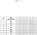
- FIG. 1 is a diagram illustrating the TDD configurations specified in LTE.
- the downlink and uplink share the same frequency such that downlink and uplink transmissions alternate in the time domain.
- the downlink and uplink signals are discriminated by subframe.
- the numbers of downlink and uplink subframes may be determined to be equal to each other or different from each other such that the number of downlink subframes is greater than that of the uplink subframes or vice versa, depending on downlink and uplink traffic loads.
- a radio frame consists of 10 subframes, and each subframe spans 1 ms.
- D denotes a downlink subframe
- U denotes an uplink subframe
- S denotes a special subframe with the three fields: Downlink Pilot Time Slot (DwPTS), Guard Period (GP), and Uplink Pilot Time Slot (UpPTS).
- DwPTS can be used for downlink control information transmission like an ordinary downlink subframe or, if its length is long enough according to the configuration of the special subframe, for downlink data transmission.
- the GP is the interval required for downlink-to-uplink switch, and its length is determined according to the network configuration.
- the UpPTS can be used for transmitting a terminal's Sounding Reference Signal (SRS) for uplink channel state estimation and a terminal's Random Access Channel (RACH).
- SRS Sounding Reference Signal
- RACH Random Access Channel
- TDD configuration #6 it may be possible to transmit downlink data and control information at subframes #0, #5, and #9 and uplink data and control information at subframes #2, #3, #4, #7, and #8.
- the subframes #1 and #6 designated as special subframes can be used for control information transmission or, depending on the case, data transmission in downlink and SRS or RACH transmission.
- the downlink subframes are not consecutive in a TDD frame. If the downlink subframes are consecutive in the TDD frame, the base station may use the consecutive downlink subframes continuously after success in Clear Channel Assessment (CCA) or extended CCA (ECCA). However, if the downlink subframes are not consecutive in the TDD frame, the base station has to perform CCA or ECCA before every downlink (DL) transmission. This is likely to be a cause of increasing channel occupancy failure of the base station in the LAA system.
- CCA Clear Channel Assessment
- ECCA extended CCA
- the TDD configurations supported in the LTE system operating in the licensed bands are configured per 10 ms.
- the LAA system operating in an unlicensed band and occupying the channel for as long a time as for the data to transmit it is not necessary to configure the TDD configurations in consideration of the fixed LTE frame size.
- the present invention proposes a method for determining a TDD frame structure and TDD configurations for use in an LAA system.
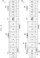
- FIG. 2 is a diagram illustrating a Frame Based Equipment (FBE) operation and a Load Based Equipment(LBE) operation of a base station.
- FBE Frame Based Equipment
- LBE Load Based Equipment
- the timing diagram 210 shows a situation where an base station or a terminal operating in the FBE mode transmits data in an unlicensed band.
- the base station or terminal in the FBE mode may perform CCA during a CCA duration 211.
- the base station in the FBE mode may perform CCA over a predetermined time duration (e.g., 20 ⁇ s) before starting data transmission.
- the CCA is an operation in which the transmitter measures an interference amount to determine whether another device currently uses the unlicensed band. If it is determined that the interference amount is less than a threshold value, the transmitter may perform transmission in the unlicensed band as denoted by reference number 213.
- the time duration in which the transmitter performs transmission is referred to as channel occupancy duration 216.
- the base station or terminal in the FBE mode may occupy the unlicensed band for at least 1 ms and up to 10 ms after performing the CCA once and then has to stay in the idle state 214 during a time period of at least 5% of the channel occupancy duration 216. This time period is referred to as idle duration 217.
- the transmitter may determine that the unlicensed band is currently occupied by another device. In this case, the transmitter may skip transmission and perform CCA during the next CCA duration 212.
- the transmitter cannot perform CCA during a predetermined time period, resulting in resource waste.
- the timing diagram 220 shows a situation where an base station or terminal in the LBE mode transmits data in an unlicensed band. Like the base station or terminal in the FBE mode, the base station or terminal in the LBE mode has to perform CCA during the CCA duration 221 with a length over at least 20 ⁇ s before starting data transmission.
- the transmitter may perform transmission as denoted by reference number 224. Otherwise if it is determined that the unlicensed band is in use by another device, the base station or terminal in the LBE mode may perform additional CCA.
- This additional CCA is referred to as extended CCA (ECCA) 223.
- the ECCA consists of N CCAs, and N is a random number selected in the range of [1, q] where q is a given number.
- the transmitter may perform transmission as denoted by reference number 224.
- the time duration in which the base station or terminal in the LBE mode performs data transmission is referred to as channel occupancy duration 225.
- the channel occupancy duration 225 lasts for up to (13/32 ⁇ q) ms and is followed by an idle duration 227 during which the transmitter stays in the idle state 226 without data transmission.
- the base station may operate in the LBE mode for downlink transmission, and the terminal may operate in one of the FBE and LBE modes for uplink transmission.
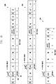
- FIG. 3A is a diagram illustrating configurations of a TDD.
- the base station may detect an idle channel during the first CCA duration 311 in the TTD frame 310.
- the TDD frame 310 includes consecutive downlink subframes 312 in which the base station may perform downlink transmission. That is, all downlink subframes are arranged consecutively in the TDD frame 310.
- the number of subframes for use in downlink transmission may vary depending on the amount of data to transmit.
- the base station may determine configuration on the subframes including the consecutive downlink subframe in a predetermined time period according to the data amount to transmit and send the configuration information to the terminal.
- the drawing depicts the TDD frame 310 with 6 downlink subframes designated for downlink data transmission.
- the base station may transmit the subframes configuration information to the terminal. Also, the base station may transmit downlink data for 6 ms because the duration of one subframe is 1 ms.
- the TDD frame 310 may include a special subframe 313 following the consecutive downlink subframes 312 and consecutive uplink subframes 314 following the special subframe 313.
- the special subframe may include an idle duration defined in the regulation.
- the other part of the special subframe may be used by the base station or terminal for data or control signal transmission.
- the subframe carrying an initial signal may be assigned subframe index 0. It may also be possible to assign subframe index 0 to the subframe canarying the first data following the initial signal. However, the subframe index determination is not limited thereto.
- the TDD frame 320 has a frame structure for use in case where no idle channel is detected in the first CCA duration 321.
- the base station may perform eCCA 323 in the next subframe, i.e., subframe 0 322.
- the time duration for performing the eCCA may be referred to as eCCA duration.
- the eCCA duration may also be called channel occupancy check duration.
- the base station may transmit downlink signals during the consecutive downlink subframes 326 starting from the next subframe, i.e., subframe 1 324.
- the channel may be in use by another channel during the duration 325 between the time point of detecting the idle state of the channel and the time point of beginning the next subframe. For this duration, the base station may transmit the initial signal to occupy the channel.
- the TDD frame 320 may also include a special subframe 327 following the consecutive downlink subframes 326 and uplink subframes 328 following the special subframe 327.
- the terminal performing uplink transmission may be changed every uplink subframe.
- the terminal may receive the information on uplink subframes for receiving downlink data.
- the terminal performs CCA or eCCA, to check whether the channel is preoccupied, for uplink transmission at the allocated subframes. If it is determined as a result of CCA or eCCA that the channel is in the idle state, the terminal may transmit uplink data in the corresponding subframes. Otherwise, if it is determined that the channel is in an occupied state, the terminal may not transmit uplink data in the corresponding subframes.
- the channel occupancy time of the terminal for uplink data transmission may be 1 ms, equal to the length of one subframe, or a multiple of 1 ms.
- the terminal may perform CCA during the CCA duration 329 included in an uplink subframe, and the CCA duration 329 may consist of the last one or n symbols of the uplink subframe. Accordingly, there may be no signal transmission between the terminal and the base station during the last 1 or n symbols of the uplink subframe.
- the CCA or eCCA may be performed in the downlink subframe or the special subframe right before the first uplink subframe 329.
- the position and length of the duration for CCA or eCCA may be changed in the uplink subframes. A detailed description thereof is made with reference to FIG. 3B .
- FIG. 3B is a diagram illustrating configurations of a TDD frame.
- the TDD frames 330 and 340 are characterized in that the CCA duration is changed in position and sized in the uplink subframes.
- the CCA duration consists of the last one or n symbols of the previous subframe.
- the CCA duration of the TDD from 330 consists of the first 1 or n symbols of the subframe.
- the base station may perform CCA during the CCA duration 332 designated at the beginning of downlink subframe 0 331 of the TDD frame 330 and, if it is determined as a result of CCA that the channel is not idle, then perform eCCA immediately.
- the terminal may also perform CCA or eCCA during first 1 or n symbols of each uplink subframe for uplink transmission. Accordingly, there may be no signal transmission between the terminal and the base station during the first 1 or n symbols of the uplink subframe.
- the TDD configuration information related to the TDD frame structure such as a start time point and number of consecutive downlink subframes, a position of the special subframe, a start time and number of consecutive uplink subframes, and CCA and ECCA durations of downlink and uplink subframes may be changed according to the data amount to be transmitted by the base station and terminals.
- the TDD frame 340 is different in that the number of consecutive downlink subframes, the number of consecutive uplink subframes, and the CCA durations are changed.
- the number of consecutive downlink subframes may be decreased in the TDD frame 340.
- the TDD frame 340 includes 5 consecutive downlink subframes while the TDD frame 330 includes 6 consecutive downlink subframes.
- the number of CCA durations may also be changed.
- a terminal transmits uplink data through an unlicensed band channel based on CCA, it may use two or more uplink subframes for data transmission according to the data amount to transmit.
- the terminal may perform CCA at an interval of two subframes in uplink.
- the base station may allocates uplink subframes to the terminal dynamically in number according to the data amount to be transmitted by each terminal and thus the interval of subframes for CCA may be dynamically changed.
- the base station occupies the channel for a time duration that is sufficient to transmit data as described above, and it is not necessary to consider the fixed LTE frame length of 10 ms in configuring the TDD frame.
- the TDD frame 350 is characterized in that the number of subframes is dynamically changed according to the data amount to be transmitted.
- the number of consecutive downlink subframes and the number of consecutive uplink subframes may be changed and, as a consequence, the frame length may be changed.
- the TDD frame 350 may include 3 consecutive downlink subframes and 2 consecutive uplink subframes that appear sequentially after eCCA.
- the frame length becomes 7 ms shorter than the LTE frame length of 10 ms.
- the TDD frame structured according to the present invention may include consecutive downlink subframes, special subframes, and consecutive uplink subframes.
- the TDD frame proposed in the present invention may be configured such that all downlink subframes are arranged consecutively and all uplink subframes are arranged consecutively. The positions of the consecutive downlink subframes, the consecutive uplink subframes, and special subframes may be changed.
- the frame is configured to have only the consecutive downlink sub frames or only the consecutive uplink sub frames.
- the terminal may check the downlink/uplink subframe configurations at the current subframe or a subframe after m subframes.
- the terminal may receive a downlink control channel (PDCCH) at the downlink subframes for performing Radio Resource Management (RRM) measurement or CSI measurement based thereon.
- the terminal may also determine one of the RRM management result and CSI measurement result for a bundle of the consecutive subframes.
- the base station may configure uplink subframes to the terminal to receive a Physical Uplink Control Channel (PUCCH) or a Sounding Reference Signal (SRS) and perform measurement thereon.
- PUCCH Physical Uplink Control Channel
- SRS Sounding Reference Signal
- the base station may transmit the TDD configuration information to notify the terminal of the TDD frame structure.
- the TDD configuration information may include at least one of the informations listed in Table 1. [Table 1] Channel occupancy start time point, channel occupancy end time point, residual channel occupancy time, frame length, frame start time point, frame end time point, downlink duration length, downlink duration start time point, downlink duration end time point, residual downlink duration length, uplink duration length, uplink duration start time point, uplink duration end time point, residual uplink duration length, CCA or ECCA duration of base station in downlink duration, CCA or ECCA duration of terminal in uplink duration, position of special subframe, presence/absence of partial subframe as part of total channel occupancy duration, and whether each subframe is an ordinary 1 ms subframe or a partial subframe shorter than 1 ms, etc.
- an LTE special subframe consists of a DwPTS, an UpPTS, and a GP, which are configured as shown in Table 2.
- the base station may notify the terminal of the end time information as follows.
- the terminal assumes that the end time point of the third symbol of the n th subframe is the downlink end time point.
- the terminal assumes that the end time point of the 6 th symbol of the n th subframe is the downlink end time point.
- the information such as the start and end time points and number of consecutive downlink subframes, the position of the special subframe, the start and end time points and number of consecutive downlink subframes, and the CCA duration may be changed according to the data amount to be transmitted by the base station and terminal at every transmission.
- the TDD configuration information may be changed at every CCA of the base station or every subframe and, as a consequence, the base station may transmit the changed TDD configuration information to the terminal through PDCCH.
- the base station may use at least one of the following methods for transmitting the TDD configuration information.
- the base station may transmit to the terminal the TDD configuration information through a control channel of the primary component carrier (PCell) operating in the licensed band.
- the control channel may include the information on Physical Downlink Control Channel (PDCCH), System Information Block (SIB), Radio Resource Control (RRC) configuration, and RRC reconfiguration.
- the base station may transmit to the terminal the information as shown in Table 3 using a new element of the Downlink Control Indicator (DCI) on PDCCH.
- DCI Downlink Control Indicator
- the base station may transmit the TDD configuration information to the terminal using a control channel (e.g., PDCCH, SIB, RRC configuration, and RRC reconfiguration) of the SCell.
- a control channel e.g., PDCCH, SIB, RRC configuration, and RRC reconfiguration
- the base station may transmit the TDD configuration information using the initial signal.
- the base station may transmit to the terminal the TDD configuration information through the PCell and, if necessary, through the SCell.
- the terminal may combine or overwrite the configuration information received through the SCell with or on the configuration information received through the PCell.
- the terminal may be configured with the channel occupancy start time point for the target carrier received along with the cross-carrier scheduling command through the downlink control channel of the PCell and then configured with the channel occupancy end time point received through the downlink control channel of the SCell in the course of the downlink operation for the SCell on the target carrier.
- the terminal may determine the downlink subframes of the SCell in consideration of both the channel occupancy start time point received through the PCell and the channel occupancy end time point received through the SCell.
- the terminal may be configured with the channel occupancy start and end time points for the target carrier received along with the cross carrier scheduling command through the downlink control channel of the PCell and then configured with the channel occupancy end time point (or residual channel occupancy time) received through the downlink control channel of the SCell in the course of performing downlink operation for the SCell on the target carrier.
- the terminal may overwrite or correct the channel occupancy end time point received through the PCell with the channel occupancy end time point (or residual channel occupancy time) received through the SCell.
- the terminal may determine the downlink subframe of the SCell in consideration of both the channel occupancy start time point received from the PCell or the overwritten or corrected channel occupancy end time point.
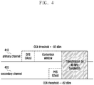
- FIG. 4 is a diagram illustrating a method for performing CCA on different types of channel.
- the base station In order to use an unlicensed band, the base station has to determine whether the unlicensed band is in use by another device in the LAA system.
- Various parameters can be used for determining whether an unlicensed band channel is occupied by another device(or for performing CCA) and these parameters may be referred to as channel occupancy parameters.
- the channel occupancy parameters may include at least one of a CCA start time, a CCA duration, a CCA threshold, an idle period, an ECCA duration, and a channel occupancy time.
- a Wi-Fi device operating in an unlicensed band such as an LAA unlicensed band also has to perform CCA and, in the case of Wi-Fi, different channel occupancy parameters are used for different types of traffic.
- IEEE 802.11e defines Enhanced Distributed Channel Access (EDCA) as a channel occupancy parameter (hereinafter, interchangeable referred to as CCA parameter, or Listen Before Talk (LBT) parameter) as shown in Table 4.
- CCA parameter channel occupancy parameter
- LBT Listen Before Talk
- the primary channel 410 and the secondary channel 420 are discriminated by function.
- the channels discriminated by function may mean the channels transmitting different types of traffic or packets.
- different LBT parameters may be used for different types of channel in a multi-channel operation.
- an Access Point (AP) or a Station (STA) may perform eCCA during a DIFS period or a random back-off period on the primary channel 410. Meanwhile, the AP or STA may perform CCA during a PIFS on the secondary channel 420 to determine whether it is possible to occupy the channel.
- AP Access Point
- STA Station
- CCA CCA during a PIFS on the secondary channel 420 to determine whether it is possible to occupy the channel.
- the AP or STA may observe the average channel occupancy time per channel to select the channel with the least average channel occupancy time.
- the types of traffic may be randomized on the respective channel; however, in the case that the channel allocation to the terminal is performed in a centralized manner as with being performed by an base station of an LTE system, it may be possible to improve the channel management efficiency and a detailed description thereof is made hereinafter.
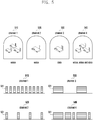
- FIG. 5 is a diagram illustrating a situation where different types of traffic are carried on different channels in an unlicensed band to which an embodiment of the present invention is applicable.
- FIG. 5 exemplifies a situation where channel 1 510 and channel 2 520 carry voice packets, channel 3 530 carries data packets, and channel 4 540 carries voice, data, and video packets.
- the voice packets 511 and 521 transmitted on the channel 1 510 and channel 2 520 may be relatively small in size in comparison with the data packet or video packet.
- the voice packet occurrence interval may be changed according to the number of APs, and the voice packets may be transmitted at a relatively short interval in comparison with the data or video packet.
- the data packet 531 transmitted on channel 3 530 and the data and video packets 541 and 542 transmitted on channel 4 540 may be relatively large in size in comparison with the voice packet.
- the data and video packets may be transmitted at a relatively long interval in comparison with the voice packet.
- FIG. 6A is a diagram illustrating a situation of transmitting LAA voice packets in an unlicensed band to which an embodiment of the present invention is applicable.
- channel 1 610 and channel 2 620 carry Wi-Fi voice packets
- channel 3 630 carries Wi-Fi data packets
- channel 4 640 carries Wi-Fi video, data, and voice packets.
- the base station can transmit the LAA voice packets 611 and 621 in the time durations with no Wi-Fi voice packet although the channel load is high.
- the voice packets transmitted by the base station and the Wi-Fi data packets are likely to collide in spite of low channel load because the Wi-Fi data packet is large in size.
- the LAA voice packets 631 and 632 transmitted on channel 3 630 may collide with the data packet 633.
- the LAA voice packets 641 and 642 transmitted on channel 4 640 may collide with the data packet 643 and the video packet 644.
- Such collision between the Wi-Fi and LAA packets may decrease the data throughputs of both the Wi-Fi and LAA systems.
- FIG. 6B is a diagram illustrating a situation of transmitting LAA data packets in an unlicensed band to which an embodiment of the present invention is applicable.
- Channel 1 650 and channel 2 660 carry Wi-Fi voice packets
- channel 3 670 carries Wi-Fi data packets
- channel 4 680 carries Wi-Fi video, data, and voice packets in a Wi-Fi network.
- an LAA base station transmits data packets on channel 1 650 and channel 2 660 carrying the Wi-Fi voice packets.
- the LAA data packets are likely to collide with the Wi-Fi voice packets if the voice packets are transmitted frequently at a short interval in spite of low channel load.
- the LAA data packet 651 transmitted on channel 1 650 may collide with the Wi-Fi voice packets 652.
- LAA data packet 681 transmitted on channel 4 680 may collide with the Wi-Fi data packet 682.
- the LAA base station may transmit the LAA data packet in the time durations with no Wi-Fi data packets as shown in the case where the LAA base station transmits the data packets on channel 3 670 carrying the Wi-Fi data packets.
- the present invention proposes a method for an LAA base station or terminal to check the channel occupancy behaviors of the devices operating on the channels and use LBT parameters suitable for the respective channels.
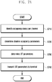
- FIG. 7A is a flowchart illustrating a LBT parameter determination procedure according to an embodiment of the present invention.
- the base station may check channel occupancy status per channel at step S710.
- the base station may scan channels available in an unlicensed band during a predetermined period and observe the channel occupancy status.
- the base station determines channel state information for determining LBT parameters at step S720 based on the channel occupancy status.
- the channel state information may include at least one of the parameters listed in Table 5.
- Table 5 Average channel occupancy time of other devices, number of transitions from channel occupancy state (hereinafter, term “busy state” is interchangeably used) to channel non-occupancy state(term “idle state” is interchangeably used), number of transitions from idle state to busy state, average time of channel occupancy durations, total time of channel occupancy durations, average time of idle durations, total time of idle durations, standard deviation of occupancy durations, and standard deviation of idle durations
- the channel state information is described in detail with reference to FIG. 8 .
- FIG. 8 is a diagram for explaining channel state information checked by an base station based on channel occupancy status according to an embodiment of the present invention.
- a time duration for the base station to check the channel state of the unlicensed band may be referred to as observation period 810.
- the base station may perform observation during the observation period 810 to determine whether the unlicensed band is occupied and generate channel state information based on the determination result.
- the base station may check occupancy durations (hereinafter, interchangeably referred to as busy durations) and non-occupancy durations (interchangeably referred to as "idle durations").
- the base station may measure received signal strength during a predetermined period and, if the received signal strength is greater than a predetermined value, may determine the corresponding duration as the occupancy duration. Otherwise, if the received signal strength is equal to or less than the predetermine value, the base station may determine the corresponding duration as the idle duration.
- the base station may check three occupancy durations 820 and three idle durations 830 in the unlicensed band.
- the base station may also check the occupancy durations of B1 821, B2 822, and B3 823.
- the base station may calculate the average occupancy time of the occupancy durations and the standard deviation 824 of the occupancy durations B1, B2, and B3.
- the base station may also check the idle durations of I1 831, I2 832, and I3 833.
- the base station may calculate the average time of the idle durations I1, I2, and I3 and standard deviation 834 of the average value.
- the base station may also determine a channel occupancy ratio 840 using the length of the observation period, the total occupancy time of the occupancy durations, and the total idle time of the idle durations.
- the base station may also determine the number of transitions 850 between the occupancy duration and the idle duration during the observation period 810.
- the base station may determine the number of transitions 850 based on the number of occupancy durations and the number of idle durations during the observation period 810.
- the base station may determine LBT parameters based on the number of transitions between the occupancy duration and the idle duration. A detailed description thereof is made later.
- the base station may also determine a number of idle slots.
- slot means a time unit for use in determining an idle state or an occupancy time. For example, one slot may have the length of 9 us.
- the base station may make a decision on idle state or occupancy state by slot and determine numbers of idle slots and occupancy slots.
- the base station may determine the number of idle slots by dividing the total length of the idle time by the length of one slot.
- the base station may also determine the ratio of the idle slots by dividing the total length of the idle time by the length of the observation period.
- the base station may also determine the radio between the number of idle slots and the number of occupancy slots (busy slots) in the observation period.
- the base station may determine the ratio between the idle slots and the occupancy slots (busy slots) by dividing the total length of the idle time by the total length of the occupancy time.
- the base station may determine the LBT parameters based on at least one of the number of idle slots, the ratio of the idle slots, and the ratio between the idle slots and the occupancy slots.
- the present invention is not limited thereto. That is, the terminal may check the channel state and determine the channel state information, and the base station may determine LBT parameters based on the channel state information determined by the terminal.
- the base station may determine LBT parameters per channel based on channel-related parameters at step S730.
- the base station may receive the channel state information from the terminal and determines the LBT parameters based on the received channel state information.
- the LBT parameters may include at least one of the parameters listed in Table 6. [Table 6] CCA start time, CCA duration, CCA threshold, channel occupancy time, idle duration, ECCA duration
- the ECCA duration may be referred to as a channel occupancy check duration.
- the ECCA duration may be determined by a contention window size of the LAA system, and the base station may calculate the contention window size based on the number of transitions from the occupancy state to the idle state, the number of idle slots, or the ratio between the number of idle slots and the number of occupancy slots, as part of the channel state information to determine the ECCA duration.
- the LBT parameters may be determined using various method and algorithms, and detailed descriptions thereof are made later.
- the base station may transmit the per-channel LBT parameters to the terminal at step S740.
- the base station may transmit the LBT parameters to the terminal through a PCell operating in the licensed band.
- the base station may transmit the LBT parameters using a PDCCH, an SIB, an RRC connection configuration message, or an RRC connection reconfiguration message of the PCell operating on the licensed band.
- FIG. 7B is a flowchart illustrating a procedure for determining LBT parameters based on a channel state according to an embodiment of the present invention.
- the base station may check the channel state of the unlicensed band during an observation period at step S751 and determine channel state information at step S752. Since these steps are similar to steps S710 and S720 of FIG. 7A , detailed descriptions thereof are omitted herein.
- the base station may perform a channel state information comparison at step S753.
- the base station may compare the channel state information determined during the current observation period and the channel state information determined during the previous observation period.
- the base station may select at least one of the number of transitions from the occupancy duration to the idle duration, the average occupancy time of the occupancy durations, and the total occupancy time of the occupancy durations included in the channel state information for use in the comparison.
- the base station may compare the parameters of the current observation period and the previous observation period.
- the base station may initialize the contention window size to the least value at step S755.
- the base station may double the contention window size at step S756.
- the base station may double the contention window size to avoid collision of packets transmitted on the same channel. Otherwise, if the parameter value of the channel state information decreases, the base station may initialize the contention window size.
- the base station may select a random number in the determined contention window size at step S757.
- the base station may perform channel occupancy assessment (LBT) for access to the unlicensed band based on the selected random number at step S758.
- LBT channel occupancy assessment
- FIG. 7C is a flowchart illustrating a procedure for determining LBT parameters based on a channel state according to another embodiment of the present invention.
- the base station at step S761 may check the channel state of the unlicensed band during an observation period and determine channel state information at step S762. Since these steps are similar to steps S710 and S720 of FIG. 7A , detailed descriptions thereof are omitted herein.
- the base station may perform a channel state information comparison at step S763.
- the base station may compare the channel state information determined during the current observation period and the channel state information determined during the previous observation period.
- the base station may select at least one of the number of transitions from the occupancy duration to the idle duration, the average occupancy time of the occupancy durations, and the total occupancy time of the occupancy durations included in the channel state information for use in the comparison.
- the base station at step S764 may compare the parameters of the current observation period and the previous observation period.
- the base station may determine a new contention window size by multiplying the contention window size by a predetermined first constant p at step S765.
- the first constant value p may be greater than 0 and less than 1.
- the base station may determine a new window size by multiplying the contention window size by a predetermined second constant value q at step S766.
- the second constant value q may be greater than 0 and less than 1.
- p and q may be determined according to a contention window size decrement/increment rate. Also, p and q may be set to values fulfilling the conditions of 0 ⁇ p ⁇ 1 and q > 1.
- the base station may select a random number in the determined contention window size at step S767.
- the base station may perform channel occupancy assessment (LBT) for access to the unlicensed band based on the selected random number at step S768.
- LBT channel occupancy assessment
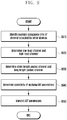
- FIG. 7D is a flowchart illustrating a procedure for determining LBT parameters based on a channel state according to still another embodiment of the present invention.
- the base station may check the channel state of the unlicensed band during an observation period at step S771, and determine channel state information at step S772. Since these steps are similar to steps S710 and S720 of FIG. 7A , detailed descriptions thereof are omitted herein.
- the base station determines a contention window size based on a pre-stored mapping table and the channel state information at step S773 .
- Table 7 is an example of the pre-stored mapping table.
- the base station may select at least one of the number of transitions from the occupancy duration to the idle duration, the average occupancy time of the occupancy durations, and the total occupancy time of the occupancy durations as the channel state information for use in determining the contention window size.
- the base station may determine the contention window size using the channel state information of the current observation period and the mapping table.
- the base station may select a random number in the determined contention window size at step S774.
- the base station may perform channel occupancy assessment (LBT) for access to the unlicensed band based on the selected number.
- LBT channel occupancy assessment
- the present invention proposes a method for selecting a channel, the method being described hereinafter.
- FIG. 9 is a flowchart illustrating a procedure for selecting a channel to which the LBT parameter determined based on channel states is applied according to an embodiment of the present invention.
- the base station may check the average occupancy time of a channel occupied by other devices at step S910.
- the average channel occupancy time of other devices may be determined based on the unlicensed band channel state checked by the base station or the terminal.
- the base station may check whether the channel is a low-load channel or a high-load channel using the average channel occupancy time at step S920. If the average occupancy time is less than a predetermined value, the base station may determine the channel as a low-load channel.
- the base station may determine whether a channel is a short packet channel or a long packet channel at step S930.
- the base station may check the packet lengths on the respective channels based on the number of transitions from the occupancy duration to the idle duration, the number of transitions from the idle state to the occupancy state, the average time of occupancy durations, and average time of idle durations included in the channel state information.
- the base station may determine that the packet transmitted on a channel with a short average occupancy time is short in length. That is, the base station may determine the channel on which the average occupancy time value is less than a predetermined value as a short packet channel. It may also be possible to determine the channel on which the number of transitions from the occupancy state to the idle state is less than a predetermined value and the average occupancy time is shorter than a predetermined length as the short packet channel.
- the above packet length determination method is only an exemplary embodiment, and the present invention is not limited thereby.
- the base station may determine at step S940 whether it is possible to apply the LBT parameters determined based on the channel condition to the channel. That is, the base station may determine whether the information acquired at the previous step is valid. This is because an irregular channel occupancy pattern makes it difficult for the base station to determine and apply LBT parameters according to the channel condition.
- the base station may use the standard deviations of the occupancy durations and idle durations.
- the base station may determine that the information acquired based on the average of the occupancy durations is invalid. In this case, the base station may not use the LBT parameters determined based on the channel condition in association with the channel with large standard deviations of the occupancy durations and idle durations.
- the base station may determine that the information acquired on the channel with an occupancy or idle duration standard deviation less than a predetermined value is valid and thus that the LBT parameters are applicable.
- the base station may apply the determined LBT parameters at step S950.
- the base station may sort the channels into 4 groups and apply the LBT parameters to the respective channels.
- FIG. 10 is a diagram illustrating a procedure for sorting channels into four channel groups.
- the four channel groups include the first channel group 1010 characterized by large packet length and high load, the second channel group 1020 characterized by small packet length and high load, the third channel group 1030 characterized by large packet size and small load, and the fourth channel group 1040 characterized by large packet size and high load.
- the base station may check occupancy states of available unlicensed band channels and determine load states of each of the channels based on the occupancy states at step S1010. For example, the base station may determine the load states of the channels using the average occupancy times and channel occupancy ratios of each of the channels. Here, the base station may compare the average occupancy times or channel occupancy ratios of the channels to sort the channels into a high-load channel category and a low-load channel category. That is, the base station may sort the channels with an average occupancy time or occupancy ratio greater than a predetermined value into a high-load channel.
- the base station may check packet lengths at step S1020.
- the base station may determine the packet length per channel based on the number of transitions between occupancy duration and idle duration and average times of occupancy durations and idle durations.
- the base station may determine at step S1030 whether the LBT parameters determined based on the channel condition are valid.
- the base station checks the validity of the information acquired on the channel using the standard deviations of the occupancy durations and idle durations. If the standard deviation is less than a predetermined value, the base station may validate the validity of the information acquired on the channel and determine and apply the LBT parameters. If it is determined that the information acquired on the channel is valid, the base station may sort the channel into one of the channel groups.
- base station may sort the channel with a high load and short packet length into the first channel group.
- the base station may apply the LBT parameters according to the per-channel conditions.
- FIG. 11 is a diagram illustrating a method for determining LBT parameters per channel according to an embodiment of the present invention.
- FIG. 11 shows two methods for determining LBT parameter per channel.
- the base station and the terminal store at least one predetermined LBT parameter set, and the base station transmits to the terminal an index of the LBT parameter set determined per channel.
- each LBT parameter set may include at least one LBT parameter.
- an LBT parameter set may include CCA duration, ECCA duration, and CCA start time.
- the base station and the terminal may store the index of the at least one parameter set, and the base station may send the terminal the index of the LBT parameter set currently in use.
- a predetermined LBT parameter set 1 1111 and a predetermined LBT parameter set 2 1112 may be stored in the base station and the terminal.
- the base station may determine to use the LBT parameters included in the LBT parameter set 1 1111 for channel 1 1130 and channel N 1133 and then transmit the index of the LBT parameter set 1 to the terminals operating on channel 1 1130 and channel N 1133.
- the base station may also determine to use the LBT parameters included in the LBT parameter set 2 1112 for channel 2 1131 and channel 3 1132 and, in this case, transmit the index of the LBT parameter set 2 to the terminals operating on the corresponding channels.
- the base station determines LBT parameters per channel and notifies the terminal of the parameters explicitly.
- the base station may check channel state per channel, determine LBT parameters based on the channel state, and transmit the parameters to the terminal.
- the base station may transmit the LBT parameters to the terminal using an SIB, a PDCCH, or an RRC configuration message. A detailed description thereof is made with reference to FIG. 12 .
- FIG. 12 is a signal flow diagram illustrating a procedure for transmitting LBT parameters to a terminal according to an embodiment of the present invention.
- an LAA base station may use a primary carrier (PCell) in a licensed band and a secondary carrier (SCell) in an unlicensed band.
- PCell primary carrier
- SCell secondary carrier
- the base station may check the channel state of the unlicensed band at step S1210.
- the terminal may check the channel state of the unlicensed band at step S1210.
- the channel state checking step of the terminal is optional.
- the base station may receive a channel state measurement report associated with the unlicensed band at step S1220.
- the measurement report may include channel state information.
- the base station may determine LBT parameters based on the base station-measured channel state and the measurement report.
- the base station may determine the LBT parameters based on the channel state measurement report received from the terminal and the occupancy parameters determined through its channel observation and analysis. For example, the base station may determine the ECCA duration by adjusting the contention window size based on the channel state.
- the base station may transmit the LBT parameters to the terminal at step S1230.
- the base station may transmit the LBT parameters using at least one of an SIB, a PDCCH, and an RRC configuration information.
- the base station may also transmit an index of an LBT parameter set or LBT parameter information using at least one of the SIB, PDCCH, and RRC configuration information.
- FIG. 13 is a block diagram illustrating a configuration of an base station according to an embodiment of the present invention.
- the base station may include a transceiver 1310, a controller 1320, and a memory 1330.
- the transceiver 1310 may communicate with a network entity.
- the transceiver 1310 may transmit TDD configuration information of a TDD frame to a terminal.
- the transceiver 1310 may also transmit downlink data to the terminal and receive uplink data from the terminal.
- the transceiver 1310 may receive a channel state measurement report from the terminal.
- the transceiver 1310 may also transmit to the terminal the LBT parameters determined based on the channel state.
- the controller 1320 may perform CCA during an initial CCA duration to determine whether an unlicensed band channel is occupied. If it is determined that the channel is occupied, the controller 1320 may perform eCCA during the next CCA duration. If it is determined as a result of CCA or eCCA that the unlicensed band channel is idle, the base station may occupy the unlicensed band channel to transmit downlink data.
- a frame may be configured to have consecutive downlink subframes. In this case, the base station may transmit downlink data during the consecutive downlink sub frames.
- the number of downlink subframes may be changed.
- the controller 1320 may also perform CCA or eCCA during the first one or n symbols of every sub frame according to the configuration of the TDD frame.
- the controller 1320 may also perform CCA or eCCA during the last one or n symbols of every subframe.
- the base station may generate TDD configuration information corresponding to the determined frame structure and transmit the TDD configuration information to the terminal.
- the controller 1320 may transmit the TDD configuration information to the terminal using the control channel of the primary carrier (PCell).
- the control channel of the PCell may include the information on PDCCH, SIB, RRC configuration, and RRC reconfiguration.
- the controller 1320 may transmit the TDD configuration information using a control channel of the SCell such as PDCCH, SIB, RRC configuration, and RRC reconfiguration of the SCell.
- the controller 1320 may transmit the TDD configuration information to the terminal using an initial signal transmitted by the base station.
- the controller 1320 may check the channel state of the unlicensed band and determine channel state information based thereon.
- the controller 1320 may also determine LBT parameters based on the channel state information. In this case, if the channel state information value increases in comparison with the previous observation period, the controller 1320 may increase the contention window size and determine the LBT parameters.
- the controller 1320 may also perform a channel access procedure with the LBT parameters to access the unlicensed band channel.
- the controller 1320 may also transmit to the terminal at least one of an index of an LBT parameter set and RRC configuration information using at least one of an SIB, a PDCCH, and RRC configuration information.
- the controller 1320 may determine the load state of the channel based on the channel occupancy time and may determine per-channel packet length based on information such as the number of transitions from occupancy state to idle state, the number of transitions from idle state to occupancy state, the average time of occupancy durations, and average time of idle durations. Additionally, the controller 1320 may determine validity of acquired information based on the standard deviation of each occupancy duration, standard deviation of each idle duration and may determine whether to apply the LBT parameter.
- the memory 1330 may store the TDD configuration information related to the TDD frame structure.
- the memory 1330 may also store CCA parameters for performing CCA.
- the memory 1330 may store LBT parameter sets including LBT parameters and indices of the LBT parameter sets.
- the memory 1330 may also store the channel state information generated based on the channel state.
- the memory 1330 may also store the information related to the channel state received from the terminal.
- FIG. 14 is a block diagram illustrating a configuration of a terminal according to an embodiment of the present invention.
- the terminal may include a transceiver 1410, a controller 1420, and a memory 1430.
- the transceiver 1410 may communicate with a network entity.
- the transceiver 1410 may receive TDD configuration information from an base station.
- the transceiver 1410 may receive downlink data from the base station and transmit uplink data to the base station.
- the transceiver 1410 may transmit a channel state measurement report to the base station.
- the controller 1410 may also receive LBT parameters from the base station.
- the controller 1420 may perform CCA during uplink subframes allocated by the base station to determine whether the unlicensed band channel is occupied. If it is determined that the channel is occupied, the terminal may not transmit uplink data. Otherwise it is determined that the channel is not occupied, the terminal may transmit uplink data to the base station.
- the controller 1420 may perform CCA or eCCA during the first one or n symbols of the uplink sub frame allocated by the base station according to the TDD frame structure.
- the controller 1420 may also perform CCA or eCCA during the last one or n symbols of the previous subframe.
- the controller 1420 may also control receiving data during consecutive downlink subframes.
- the controller 1420 may also control receiving the TDD configuration information corresponding to the frame structure from the base station.
- the controller 1420 may check an unlicensed band channel state and determine channel state information based thereon.
- the controller 1420 may also control transmitting the channel state information to the base station.
- the channel state information may be used for determining the LBT parameters.
- the controller 1420 may also control receiving LBT parameter information from the base station.
- the controller 1420 may also control receiving an index of an LBT parameter set or LBT parameter information through at least one of an SIB, a PDCCH, and RRC configuration information.
- the memory 1430 may store the TDD configuration information received from the base station.
- the memory 1430 may also store the CCA parameters for use in performing CCA.
- the memory 1430 may store LBT parameter sets including LBT parameters and indices of the LBT parameter sets.
- the memory 1430 may also store the channel state information generated based on the channel state.
Description
- The present invention relates to a mobile communication system and, in particular, to a communication method and apparatus operating in an unlicensed band in the mobile communication system.
- To meet the demand for wireless data traffic having increased since deployment of 4G communication systems, efforts have been made to develop an improved 5G or pre-5G communication system. Therefore, the 5G or pre-5G communication system is also called a 'Beyond 4G Network' or a 'Post LTE System'.
- The 5G communication system is considered to be implemented in higher frequency (mmWave) bands, e.g., 60GHz bands, so as to accomplish higher data rates. To decrease propagation loss of the radio waves and increase the transmission distance, the beamforming, massive multiple-input multiple-output (MIMO), Full Dimensional MIMO (FD-MIMO), array antenna, an analog beam forming, large scale antenna techniques are discussed in 5G communication systems.
- In addition, in 5G communication systems, development for system network improvement is under way based on advanced small cells, cloud Radio Access Networks (RANs), ultra-dense networks, device-to-device (D2D) communication, wireless backhaul, moving network, cooperative communication, Coordinated Multi-Points (CoMP), reception-end interference cancellation and the like.
- In the 5G system, Hybrid FSK and QAM Modulation (FQAM) and sliding window superposition coding (SWSC) as an advanced coding modulation (ACM), and filter bank multi carrier(FBMC), non-orthogonal multiple access(NOMA), and sparse code multiple access (SCMA) as an advanced access technology have been developed.
- Mobile communication systems were developed to provide subscribers with voice communication services on the move. Recently, mobile communication systems have evolved to the level of supporting high speed data communication services beyond the early voice-oriented services. However, the resource shortage and user requirements for higher speed services are spurring evolution towards increasingly more advanced mobile communication systems.
- As one of the next-generation mobile communication systems to meet such requirements, standardization for a Long-Term Evolution (LTE) system is underway in the 3rd Generation Partnership Project (3GPP). LTE is a technology designed to provide high speed packet-based communication of up to 100 Mbps and aims at commercial deployment around 2010. In order to accomplish this aim, discussions are being held on several schemes: one scheme for reducing the number of nodes located in a communication path by simplifying a configuration of the network, and another scheme for maximally approximating wireless protocols to wireless channels.
- Recently, a technique called Licensed Assisted Access (LAA) has been proposed to improve frequency utilization efficiency by using Carrier Aggregation (CA) across licensed and unlicensed bands.
- As in LTE systems, Time Division Duplexing (TDD) is used in an LLA system. There is therefore a need of a method for determining a TDD frame structure and TDD configuration information for use in the LAA system.
- LG Electronics: "Candidate solutions for LAA operation", 3GPP DRAFT; R1-144042 LAA CANDIDATE SOLUTIONS_FINAL, 3rd Generation Partnership Project (3GPP), VOL. RAN WG1, no. Ljubljana, Slovenia; 20141006-20141010; 5 October 2014 discloses potential candidate solutions for LAA operation in terms of radio access schemes for coexistence with other systems/operators and the relevant improvement for reliable operation/utilization in unlicensed band.
- The present invention has been conceived to solve the above problems. The present invention proposes a method for determining parameters for checking unlicensed band channel occupancy based on channel condition.
- In accordance with an aspect of the present invention, a communication method of a base station in a mobile communication system is defined according to
Claim 1. - In accordance with another aspect of the present invention, a base station of a mobile communication system is defined according to
Claim 5. - In accordance with another aspect of the present invention, a communication method of a terminal of a mobile communication system is defined according to
Claim 9. - In accordance with still another aspect of the present invention, a terminal of a mobile communication system is defined according to
Claim 13. - The present invention is advantageous in terms of increasing data processing throughput by determining CCA parameters depending on channel condition.
-
-
FIG. 1 is a diagram illustrating the TDD configurations specified in LTE; -
FIG. 2 is a diagram illustrating a Frame Based Equipment (FBE) operation and a Load Based Equipment(LBE) operation of a base station; -
FIG. 3A is a diagram illustrating configurations of a TDD frame; -
FIG. 3B is a diagram illustrating configurations of a TDD frame; -
FIG. 4 is a diagram illustrating a method for performing CCA on different types of channel; -
FIG. 5 is a diagram illustrating a situation where different types of traffic are carried on different channels in an unlicensed band to which an embodiment of the present invention is applicable; -
FIG. 6A is a diagram illustrating a situation of transmitting LAA voice packets in an unlicensed band to which an embodiment of the present invention is applicable; -
FIG. 6B is a diagram illustrating a situation of transmitting LAA data packets in an unlicensed band to which an embodiment of the present invention is applicable; -
FIG. 7A is a flowchart illustrating an LBT parameter determination procedure according to an embodiment of the present invention; -
FIG. 7B is a flowchart illustrating a procedure for determining LBT parameters based on a channel state according to an embodiment of the present invention; -
FIG. 7C is a flowchart illustrating a procedure for determining LBT parameters based on a channel state according to another embodiment of the present invention; -
FIG. 7D is a flowchart illustrating a procedure for determining LBT parameters based on a channel state according to still another embodiment of the present invention; -
FIG. 8 is a diagram for explaining channel state information checked by an base station based on channel occupancy status according to an embodiment of the present invention; -
FIG. 9 is a flowchart illustrating a procedure for selecting a channel to which the LBT parameter determined based on channel states is applied according to an embodiment of the present invention; -
FIG. 10 is a diagram illustrating a procedure for sorting channels into four channel groups; -
FIG. 11 is a diagram illustrating a method for determining LBT parameters per channel according to an embodiment of the present invention; -
FIG. 12 is a signal flow diagram illustrating a procedure for transmitting LBT parameters to a terminal according to an embodiment of the present invention; -
FIG. 13 is a block diagram illustrating a configuration of an base station according to an embodiment of the present invention; and -
FIG. 14 is a block diagram illustrating a configuration of a terminal according to an embodiment of the present invention. - Exemplary embodiments are described in detail with reference to the accompanying drawings. The same reference numbers are used throughout the drawings to refer to the same or like parts. Detailed descriptions of well-known functions and structures incorporated herein may be omitted to avoid obscuring the subject matter of the present invention.
- Detailed descriptions of technical specifications well-known in the art and unrelated directly to the present invention may be omitted to avoid obscuring the subject matter of the present invention. This aims to omit unnecessary description so as to make the subject matter of the present invention clear.
- For the same reason, some elements are exaggerated, omitted, or simplified in the drawings and, in practice, the elements may have sizes and/or shapes different from those shown in the drawings. Throughout the drawings, the same or equivalent parts are indicated by the same reference numbers.
- Advantages and features of the present invention and methods of accomplishing the same may be understood more readily by reference to the following detailed description of exemplary embodiments and the accompanying drawings. The present invention may, however, be embodied in many different forms and should not be construed as being limited to the exemplary embodiments set forth herein. Rather, these exemplary embodiments are provided so that this disclosure will be thorough and complete and will fully convey the concept of the invention to those skilled in the art, and the present invention will only be defined by the appended claims. Like reference numerals refer to like elements throughout the specification.
- It will be understood that each block of the flowcharts and/or block diagrams, and combinations of blocks in the flowcharts and/or block diagrams, can be implemented by computer program instructions. These computer program instructions may be provided to a processor of a general-purpose computer, special purpose computer, or other programmable data processing apparatus, such that the instructions which are executed via the processor of the computer or other programmable data processing apparatus create means for implementing the functions/acts specified in the flowcharts and/or block diagrams. These computer program instructions may also be stored in a non-transitory computer-readable memory that can direct a computer or other programmable data processing apparatus to function in a particular manner, such that the instructions stored in the non-transitory computer-readable memory produce manufacture articles embedding instruction means which implement the function/act specified in the flowchart s and/or block diagrams. The computer program instructions may also be loaded onto a computer or other programmable data processing apparatus to cause a series of operational steps to be performed on the computer or other programmable apparatus to produce a computer implemented process such that the instructions which are executed on the computer or other programmable apparatus provide steps for implementing the functions/acts specified in the flowcharts and/or block diagrams.
- Furthermore, the respective block diagrams may illustrate parts of modules, segments, or codes including at least one or more executable instructions for performing specific logic function(s). Moreover, it should be noted that the functions of the blocks may be performed in a different order in several modifications. For example, two successive blocks may be performed substantially at the same time or may be performed in reverse order according to their functions.
- According to various embodiments of the present disclosure, the term "module", means, but is not limited to, a software or hardware component, such as a Field Programmable Gate Array (FPGA) or Application Specific Integrated Circuit (ASIC), that performs certain tasks. A module may advantageously be configured to reside on the addressable storage medium and configured to be executed on one or more processors. Thus, a module may include, by way of example, components, such as software components, object-oriented software components, class components and task components, processes, functions, attributes, procedures, subroutines, segments of program code, drivers, firmware, microcode, circuitry, data, databases, data structures, tables, arrays, and variables. The functionality provided for in the components and modules may be combined into fewer components and modules or further separated into additional components and modules. In addition, the components and modules may be implemented such that they execute one or more CPUs in a device or a secure multimedia card.
-
FIG. 1 is a diagram illustrating the TDD configurations specified in LTE. - In a TDD communication system, the downlink and uplink share the same frequency such that downlink and uplink transmissions alternate in the time domain. In LTE TDD, the downlink and uplink signals are discriminated by subframe. The numbers of downlink and uplink subframes may be determined to be equal to each other or different from each other such that the number of downlink subframes is greater than that of the uplink subframes or vice versa, depending on downlink and uplink traffic loads. In LTE, a radio frame consists of 10 subframes, and each subframe spans 1 ms.
- In reference to
FIG. 1 , D denotes a downlink subframe, U denotes an uplink subframe, and S denotes a special subframe with the three fields: Downlink Pilot Time Slot (DwPTS), Guard Period (GP), and Uplink Pilot Time Slot (UpPTS). The DwPTS can be used for downlink control information transmission like an ordinary downlink subframe or, if its length is long enough according to the configuration of the special subframe, for downlink data transmission. The GP is the interval required for downlink-to-uplink switch, and its length is determined according to the network configuration. The UpPTS can be used for transmitting a terminal's Sounding Reference Signal (SRS) for uplink channel state estimation and a terminal's Random Access Channel (RACH). - For example, in case of
TDD configuration # 6, it may be possible to transmit downlink data and control information atsubframes # 0, #5, and #9 and uplink data and control information atsubframes # 2, #3, #4, #7, and #8. Thesubframes # 1 and #6 designated as special subframes can be used for control information transmission or, depending on the case, data transmission in downlink and SRS or RACH transmission. - Applying the TDD configurations to an LAA system may cause problems as follows.
- First, in the TDD configurations with a 5 ms switch periodicity, the downlink subframes are not consecutive in a TDD frame. If the downlink subframes are consecutive in the TDD frame, the base station may use the consecutive downlink subframes continuously after success in Clear Channel Assessment (CCA) or extended CCA (ECCA). However, if the downlink subframes are not consecutive in the TDD frame, the base station has to perform CCA or ECCA before every downlink (DL) transmission. This is likely to be a cause of increasing channel occupancy failure of the base station in the LAA system.
- Second, in the TDD configurations with a 5 ms switch periodicity, two special subframes exist. This may cause a problem in that Wi-Fi preoccupies the channel when the base station or terminal does not transit any signal in the special subframes.
- Third, the TDD configurations supported in the LTE system operating in the licensed bands are configured per 10 ms. In the LAA system operating in an unlicensed band and occupying the channel for as long a time as for the data to transmit, it is not necessary to configure the TDD configurations in consideration of the fixed LTE frame size.
- For this reason, the present invention proposes a method for determining a TDD frame structure and TDD configurations for use in an LAA system.
-
FIG. 2 is a diagram illustrating a Frame Based Equipment (FBE) operation and a Load Based Equipment(LBE) operation of a base station. - In reference to
FIG. 2 , the timing diagram 210 shows a situation where an base station or a terminal operating in the FBE mode transmits data in an unlicensed band. The base station or terminal in the FBE mode may perform CCA during aCCA duration 211. The base station in the FBE mode may perform CCA over a predetermined time duration (e.g., 20 µs) before starting data transmission. - The CCA is an operation in which the transmitter measures an interference amount to determine whether another device currently uses the unlicensed band. If it is determined that the interference amount is less than a threshold value, the transmitter may perform transmission in the unlicensed band as denoted by
reference number 213. Here, the time duration in which the transmitter performs transmission is referred to aschannel occupancy duration 216. - The base station or terminal in the FBE mode may occupy the unlicensed band for at least 1 ms and up to 10 ms after performing the CCA once and then has to stay in the
idle state 214 during a time period of at least 5% of thechannel occupancy duration 216. This time period is referred to asidle duration 217. - Otherwise, if it is determined that the interference amount is equal to or greater than the threshold value, the transmitter may determine that the unlicensed band is currently occupied by another device. In this case, the transmitter may skip transmission and perform CCA during the
next CCA duration 212. - However, in the case that, as a result of CCA, it is determined that the unlicensed band is occupied by another device, the transmitter cannot perform CCA during a predetermined time period, resulting in resource waste.
- The timing diagram 220 shows a situation where an base station or terminal in the LBE mode transmits data in an unlicensed band. Like the base station or terminal in the FBE mode, the base station or terminal in the LBE mode has to perform CCA during the
CCA duration 221 with a length over at least 20 µs before starting data transmission. - If it is determined as a result of CCA that the unlicensed band is not in use by another device, the transmitter may perform transmission as denoted by
reference number 224. Otherwise if it is determined that the unlicensed band is in use by another device, the base station or terminal in the LBE mode may perform additional CCA. This additional CCA is referred to as extended CCA (ECCA) 223. The ECCA consists of N CCAs, and N is a random number selected in the range of [1, q] where q is a given number. - If it is determined as a result of ECCA that the unlicensed band is not in use by another device, the transmitter may perform transmission as denoted by
reference number 224. Here, the time duration in which the base station or terminal in the LBE mode performs data transmission is referred to aschannel occupancy duration 225. Thechannel occupancy duration 225 lasts for up to (13/32∗q) ms and is followed by anidle duration 227 during which the transmitter stays in theidle state 226 without data transmission. - In the present invention, the base station may operate in the LBE mode for downlink transmission, and the terminal may operate in one of the FBE and LBE modes for uplink transmission.
-
FIG. 3A is a diagram illustrating configurations of a TDD. - In reference to
FIG. 3A , the base station may detect an idle channel during the first CCA duration 311 in theTTD frame 310. In this embodiment, theTDD frame 310 includesconsecutive downlink subframes 312 in which the base station may perform downlink transmission. That is, all downlink subframes are arranged consecutively in theTDD frame 310. Here, the number of subframes for use in downlink transmission may vary depending on the amount of data to transmit. The base station may determine configuration on the subframes including the consecutive downlink subframe in a predetermined time period according to the data amount to transmit and send the configuration information to the terminal. - The drawing depicts the
TDD frame 310 with 6 downlink subframes designated for downlink data transmission. In this case, the base station may transmit the subframes configuration information to the terminal. Also, the base station may transmit downlink data for 6 ms because the duration of one subframe is 1 ms. - The
TDD frame 310 may include aspecial subframe 313 following theconsecutive downlink subframes 312 andconsecutive uplink subframes 314 following thespecial subframe 313. - The special subframe may include an idle duration defined in the regulation. The other part of the special subframe may be used by the base station or terminal for data or control signal transmission.
- In the
TDD frame 310, the subframe carrying an initial signal may be assignedsubframe index 0. It may also be possible to assignsubframe index 0 to the subframe canarying the first data following the initial signal. However, the subframe index determination is not limited thereto. - In the drawing, the
TDD frame 320 has a frame structure for use in case where no idle channel is detected in the first CCA duration 321. - If no idle channel is detected as a result of CCA in the first CCA duration 321 of the
TDD frame 320, the base station may performeCCA 323 in the next subframe, i.e.,subframe 0 322. Here, the time duration for performing the eCCA may be referred to as eCCA duration. The eCCA duration may also be called channel occupancy check duration. - If it is determined that the channel is in the idle state as a result of
eCCA 323 insubframe 0 322, the base station may transmit downlink signals during theconsecutive downlink subframes 326 starting from the next subframe, i.e.,subframe 1 324. - However, the channel may be in use by another channel during the
duration 325 between the time point of detecting the idle state of the channel and the time point of beginning the next subframe. For this duration, the base station may transmit the initial signal to occupy the channel. - The
TDD frame 320 may also include aspecial subframe 327 following theconsecutive downlink subframes 326 anduplink subframes 328 following thespecial subframe 327. - In uplink, the terminal performing uplink transmission may be changed every uplink subframe. The terminal may receive the information on uplink subframes for receiving downlink data. The terminal performs CCA or eCCA, to check whether the channel is preoccupied, for uplink transmission at the allocated subframes. If it is determined as a result of CCA or eCCA that the channel is in the idle state, the terminal may transmit uplink data in the corresponding subframes. Otherwise, if it is determined that the channel is in an occupied state, the terminal may not transmit uplink data in the corresponding subframes. The channel occupancy time of the terminal for uplink data transmission may be 1 ms, equal to the length of one subframe, or a multiple of 1 ms.
- The terminal may perform CCA during the
CCA duration 329 included in an uplink subframe, and theCCA duration 329 may consist of the last one or n symbols of the uplink subframe. Accordingly, there may be no signal transmission between the terminal and the base station during the last 1 or n symbols of the uplink subframe. - In the case of the terminal allocated the
first uplink subframe 329, i.e.,subframe 7, of theTDD frame 320, the CCA or eCCA may be performed in the downlink subframe or the special subframe right before thefirst uplink subframe 329. - However, the position and length of the duration for CCA or eCCA may be changed in the uplink subframes. A detailed description thereof is made with reference to
FIG. 3B . -
FIG. 3B is a diagram illustrating configurations of a TDD frame. - In reference to
FIG. 3B , the TDD frames 330 and 340 are characterized in that the CCA duration is changed in position and sized in the uplink subframes. - In the case of the TDD frames 310 and 320, the CCA duration consists of the last one or n symbols of the previous subframe. Meanwhile, the CCA duration of the TDD from 330 consists of the first 1 or n symbols of the subframe.
- Accordingly, the base station may perform CCA during the
CCA duration 332 designated at the beginning ofdownlink subframe 0 331 of theTDD frame 330 and, if it is determined as a result of CCA that the channel is not idle, then perform eCCA immediately. - The terminal may also perform CCA or eCCA during first 1 or n symbols of each uplink subframe for uplink transmission. Accordingly, there may be no signal transmission between the terminal and the base station during the first 1 or n symbols of the uplink subframe.
- Meanwhile, the TDD configuration information related to the TDD frame structure such as a start time point and number of consecutive downlink subframes, a position of the special subframe, a start time and number of consecutive uplink subframes, and CCA and ECCA durations of downlink and uplink subframes may be changed according to the data amount to be transmitted by the base station and terminals.
- The
TDD frame 340 is different in that the number of consecutive downlink subframes, the number of consecutive uplink subframes, and the CCA durations are changed. - If the amount of data to transmit is small, the number of consecutive downlink subframes may be decreased in the
TDD frame 340. TheTDD frame 340 includes 5 consecutive downlink subframes while theTDD frame 330 includes 6 consecutive downlink subframes. - The number of CCA durations may also be changed. In the case that a terminal transmits uplink data through an unlicensed band channel based on CCA, it may use two or more uplink subframes for data transmission according to the data amount to transmit. In reference to
TDD frame 340, the terminal may perform CCA at an interval of two subframes in uplink. However, the base station may allocates uplink subframes to the terminal dynamically in number according to the data amount to be transmitted by each terminal and thus the interval of subframes for CCA may be dynamically changed. - In the case of the LAA system, however, the base station occupies the channel for a time duration that is sufficient to transmit data as described above, and it is not necessary to consider the fixed LTE frame length of 10 ms in configuring the TDD frame.
- The
TDD frame 350 is characterized in that the number of subframes is dynamically changed according to the data amount to be transmitted. In theTDD frame 350, the number of consecutive downlink subframes and the number of consecutive uplink subframes may be changed and, as a consequence, the frame length may be changed. - In detail, the
TDD frame 350 may include 3 consecutive downlink subframes and 2 consecutive uplink subframes that appear sequentially after eCCA. In this case, the frame length becomes 7 ms shorter than the LTE frame length of 10 ms. - As described above, the TDD frame structured according to the present invention may include consecutive downlink subframes, special subframes, and consecutive uplink subframes. The TDD frame proposed in the present invention may be configured such that all downlink subframes are arranged consecutively and all uplink subframes are arranged consecutively. The positions of the consecutive downlink subframes, the consecutive uplink subframes, and special subframes may be changed.
- It may also be possible that the frame is configured to have only the consecutive downlink sub frames or only the consecutive uplink sub frames.
- If the base station transmits the TDD frame configuration information to a terminal at the current subframe or a subframe before n subframes, the terminal may check the downlink/uplink subframe configurations at the current subframe or a subframe after m subframes. The terminal may receive a downlink control channel (PDCCH) at the downlink subframes for performing Radio Resource Management (RRM) measurement or CSI measurement based thereon. The terminal may also determine one of the RRM management result and CSI measurement result for a bundle of the consecutive subframes. The base station may configure uplink subframes to the terminal to receive a Physical Uplink Control Channel (PUCCH) or a Sounding Reference Signal (SRS) and perform measurement thereon.
- In order to apply the TDD frame structure proposed in the present invention to an LAA system, the base station may transmit the TDD configuration information to notify the terminal of the TDD frame structure. The TDD configuration information may include at least one of the informations listed in Table 1.
[Table 1] Channel occupancy start time point, channel occupancy end time point, residual channel occupancy time, frame length, frame start time point, frame end time point, downlink duration length, downlink duration start time point, downlink duration end time point, residual downlink duration length, uplink duration length, uplink duration start time point, uplink duration end time point, residual uplink duration length, CCA or ECCA duration of base station in downlink duration, CCA or ECCA duration of terminal in uplink duration, position of special subframe, presence/absence of partial subframe as part of total channel occupancy duration, and whether each subframe is an ordinary 1 ms subframe or a partial subframe shorter than 1 ms, etc. - Among the above information, the channel occupancy end time point, frame end time point, downlink duration end time point, and uplink duration end point may be notified to the terminal by transmitting the corresponding time points explicitly or using the special subframe structure specified in LTE. As described above, an LTE special subframe consists of a DwPTS, an UpPTS, and a GP, which are configured as shown in Table 2.
[Table 2] Configuration 3GPP release DwPTS UpPTS Number of slots/subframe (Ts) (Ts) Dw GP Up 0 8 6592 2192 3 10 1 1 8 19760 2192 9 4 1 2 8 21952 2192 10 3 1 3 8 24144 2192 11 2 1 4 8 26336 2192 12 1 1 5 8 6592 4384 3 9 2 6 8 19760 4384 9 3 2 7 8 21952 4384 10 2 2 8 8 24144 4384 11 1 2 9 11 13168 4384 6 6 2 - The base station may notify the terminal of the end time information as follows.
- If the base station notifies the terminal that the nth subframe is the last downlink subframe and has the
special subframe configuration 0, the terminal assumes that the end time point of the third symbol of the nth subframe is the downlink end time point. - If the base station notifies the terminal that the nth subframe is the last downlink subframe and has the
special subframe configuration 9, the terminal assumes that the end time point of the 6th symbol of the nth subframe is the downlink end time point. - As described above, the information such as the start and end time points and number of consecutive downlink subframes, the position of the special subframe, the start and end time points and number of consecutive downlink subframes, and the CCA duration may be changed according to the data amount to be transmitted by the base station and terminal at every transmission. The TDD configuration information may be changed at every CCA of the base station or every subframe and, as a consequence, the base station may transmit the changed TDD configuration information to the terminal through PDCCH.
- The base station may use at least one of the following methods for transmitting the TDD configuration information.
- If the base station is performing CCA or eCCA for a secondary component carrier (SCell) operating in the unlicensed band, it may transmit to the terminal the TDD configuration information through a control channel of the primary component carrier (PCell) operating in the licensed band. Here, the control channel may include the information on Physical Downlink Control Channel (PDCCH), System Information Block (SIB), Radio Resource Control (RRC) configuration, and RRC reconfiguration. For example, the base station may transmit to the terminal the information as shown in Table 3 using a new element of the Downlink Control Indicator (DCI) on PDCCH.
[Table 3] Format 0 (example, other formats can be used for the same purpose) Field name Length Comment Flag for format0/ format1A differentiation 1 Hopping flag 1 N_ULhop 1 (1.4 MHz) Applicable only when Hopping flag is set 1 (3 MHz) 1 (5 MHz) 2 (10 MHz) 2 (15 MHz) 2 (20 MHz) Resource block assignment 5 (1.4 MHz) 7 (3 MHz) 7 (5 MHz) 11 (10 MHz) 12 (15 MHz) 13 (20 MHz) MCS and RV 5 NDI (New Data Indicator) 1 TPC for PUSCH 2 Cyclic shift for DM RS 3 UL index (TDD only) 2 This field is present only for TDD operation with uplink- downlink configuration 0Downlink Assignment Index (DAI) 2 Only for TDD Operation with uplink-downlink configurations 1-6 CQI request (1 bit) 1 LAA information (newly added element) N bits At least one of the elements listed in Table 1 can be transmitted from the base station to the terminal in this way. - If the base station performs CCA or eCCA in the SCell operating in the unlicensed band to occupy the channel, it may transmit the TDD configuration information to the terminal using a control channel (e.g., PDCCH, SIB, RRC configuration, and RRC reconfiguration) of the SCell.
- Also, if the base station performs CCA or eCCA in the SCell operating in the unlicensed band to occupy the channel, it may transmit the TDD configuration information using the initial signal.
- The base station may transmit to the terminal the TDD configuration information through the PCell and, if necessary, through the SCell. The terminal may combine or overwrite the configuration information received through the SCell with or on the configuration information received through the PCell.
- As an example of the method for combining the configuration information received through the PCell and the configuration information received through the SCell, the terminal may be configured with the channel occupancy start time point for the target carrier received along with the cross-carrier scheduling command through the downlink control channel of the PCell and then configured with the channel occupancy end time point received through the downlink control channel of the SCell in the course of the downlink operation for the SCell on the target carrier. The terminal may determine the downlink subframes of the SCell in consideration of both the channel occupancy start time point received through the PCell and the channel occupancy end time point received through the SCell.
- As an example of the method for overwriting the configuration information received through the SCell on the configuration received through the PCell, the terminal may be configured with the channel occupancy start and end time points for the target carrier received along with the cross carrier scheduling command through the downlink control channel of the PCell and then configured with the channel occupancy end time point (or residual channel occupancy time) received through the downlink control channel of the SCell in the course of performing downlink operation for the SCell on the target carrier. The terminal may overwrite or correct the channel occupancy end time point received through the PCell with the channel occupancy end time point (or residual channel occupancy time) received through the SCell. The terminal may determine the downlink subframe of the SCell in consideration of both the channel occupancy start time point received from the PCell or the overwritten or corrected channel occupancy end time point.
-
FIG. 4 is a diagram illustrating a method for performing CCA on different types of channel. - In order to use an unlicensed band, the base station has to determine whether the unlicensed band is in use by another device in the LAA system. Various parameters can be used for determining whether an unlicensed band channel is occupied by another device(or for performing CCA) and these parameters may be referred to as channel occupancy parameters. The channel occupancy parameters may include at least one of a CCA start time, a CCA duration, a CCA threshold, an idle period, an ECCA duration, and a channel occupancy time.
- Meanwhile, a Wi-Fi device operating in an unlicensed band such as an LAA unlicensed band also has to perform CCA and, in the case of Wi-Fi, different channel occupancy parameters are used for different types of traffic. For example, IEEE 802.11e defines Enhanced Distributed Channel Access (EDCA) as a channel occupancy parameter (hereinafter, interchangeable referred to as CCA parameter, or Listen Before Talk (LBT) parameter) as shown in Table 4.
[Table 4] Minimum contention window size (CWmin) Maximum contention window size (CWmax) Max TXOP Background 15 1023 Best effort 15 1023 3.008 ms Video 7 15 1.504 ms Voice 3 7 Legacy 15 1023 - In reference to
FIG. 4 , theprimary channel 410 and thesecondary channel 420 are discriminated by function. The channels discriminated by function may mean the channels transmitting different types of traffic or packets. As described above, since the Wi-Fi system uses traffic-specific channel occupancy parameters, different LBT parameters may be used for different types of channel in a multi-channel operation. - For example, an Access Point (AP) or a Station (STA) may perform eCCA during a DIFS period or a random back-off period on the
primary channel 410. Meanwhile, the AP or STA may perform CCA during a PIFS on thesecondary channel 420 to determine whether it is possible to occupy the channel. - Since the Wi-Fi system uses the same LBT parameter on different physical channels, the AP or STA have no preference for any specific channel. Accordingly, the AP or STA may observe the average channel occupancy time per channel to select the channel with the least average channel occupancy time.
- By selecting a channel in this way, the types of traffic may be randomized on the respective channel; however, in the case that the channel allocation to the terminal is performed in a centralized manner as with being performed by an base station of an LTE system, it may be possible to improve the channel management efficiency and a detailed description thereof is made hereinafter.
-
FIG. 5 is a diagram illustrating a situation where different types of traffic are carried on different channels in an unlicensed band to which an embodiment of the present invention is applicable. -
FIG. 5 exemplifies a situation wherechannel 1 510 andchannel 2 520 carry voice packets,channel 3 530 carries data packets, andchannel 4 540 carries voice, data, and video packets. - The
voice packets channel 1 510 andchannel 2 520 may be relatively small in size in comparison with the data packet or video packet. The voice packet occurrence interval may be changed according to the number of APs, and the voice packets may be transmitted at a relatively short interval in comparison with the data or video packet. - Meanwhile, the
data packet 531 transmitted onchannel 3 530 and the data andvideo packets 541 and 542 transmitted onchannel 4 540 may be relatively large in size in comparison with the voice packet. The data and video packets may be transmitted at a relatively long interval in comparison with the voice packet. -
FIG. 6A is a diagram illustrating a situation of transmitting LAA voice packets in an unlicensed band to which an embodiment of the present invention is applicable. - Similar to the situation of
FIG. 5 , in the situation ofFIG. 6A ,channel 1 610 andchannel 2 620 carry Wi-Fi voice packets,channel 3 630 carries Wi-Fi data packets, andchannel 4 640 carries Wi-Fi video, data, and voice packets. - In the case of attempting LAA voice packet transmission on channel 1610 and
channel 2 620 carrying the Wi-Fi voice packets, the base station can transmit theLAA voice packets - Meanwhile, in the case of attempting LAA voice packet transmission on
channel 3 630 andchannel 4 640 carrying data packets, the voice packets transmitted by the base station and the Wi-Fi data packets are likely to collide in spite of low channel load because the Wi-Fi data packet is large in size. For example, theLAA voice packets channel 3 630 may collide with thedata packet 633. Also, theLAA voice packets channel 4 640 may collide with thedata packet 643 and thevideo packet 644. - Such collision between the Wi-Fi and LAA packets may decrease the data throughputs of both the Wi-Fi and LAA systems.
-
FIG. 6B is a diagram illustrating a situation of transmitting LAA data packets in an unlicensed band to which an embodiment of the present invention is applicable. -
Channel 1 650 andchannel 2 660 carry Wi-Fi voice packets,channel 3 670 carries Wi-Fi data packets, andchannel 4 680 carries Wi-Fi video, data, and voice packets in a Wi-Fi network. - It is assumed that an LAA base station transmits data packets on
channel 1 650 andchannel 2 660 carrying the Wi-Fi voice packets. In this case, the LAA data packets are likely to collide with the Wi-Fi voice packets if the voice packets are transmitted frequently at a short interval in spite of low channel load. For example, theLAA data packet 651 transmitted onchannel 1 650 may collide with the Wi-Fi voice packets 652. - Also, the
LAA data packet 681 transmitted onchannel 4 680 may collide with the Wi-Fi data packet 682. - However, if the Wi-Fi data packets are transmitted at a long interval, the LAA base station may transmit the LAA data packet in the time durations with no Wi-Fi data packets as shown in the case where the LAA base station transmits the data packets on
channel 3 670 carrying the Wi-Fi data packets. - If the channel occupancy time is short and if the types of traffic carried on the channel are similar, it may be possible to use the channel more efficiently. For this reason, the present invention proposes a method for an LAA base station or terminal to check the channel occupancy behaviors of the devices operating on the channels and use LBT parameters suitable for the respective channels.
-
FIG. 7A is a flowchart illustrating a LBT parameter determination procedure according to an embodiment of the present invention. - In reference to
FIG. 7A , the base station may check channel occupancy status per channel at step S710. The base station may scan channels available in an unlicensed band during a predetermined period and observe the channel occupancy status. - Next, the base station determines channel state information for determining LBT parameters at step S720 based on the channel occupancy status.
- The channel state information may include at least one of the parameters listed in Table 5.
[Table 5] Average channel occupancy time of other devices, number of transitions from channel occupancy state (hereinafter, term "busy state" is interchangeably used) to channel non-occupancy state(term "idle state" is interchangeably used), number of transitions from idle state to busy state, average time of channel occupancy durations, total time of channel occupancy durations, average time of idle durations, total time of idle durations, standard deviation of occupancy durations, and standard deviation of idle durations - The channel state information is described in detail with reference to
FIG. 8 . -
FIG. 8 is a diagram for explaining channel state information checked by an base station based on channel occupancy status according to an embodiment of the present invention. - In reference to
FIG. 8 , a time duration for the base station to check the channel state of the unlicensed band may be referred to asobservation period 810. The base station may perform observation during theobservation period 810 to determine whether the unlicensed band is occupied and generate channel state information based on the determination result. - The base station may check occupancy durations (hereinafter, interchangeably referred to as busy durations) and non-occupancy durations (interchangeably referred to as "idle durations").
- The base station may measure received signal strength during a predetermined period and, if the received signal strength is greater than a predetermined value, may determine the corresponding duration as the occupancy duration. Otherwise, if the received signal strength is equal to or less than the predetermine value, the base station may determine the corresponding duration as the idle duration.
- In
FIG. 8 , the base station may check threeoccupancy durations 820 and threeidle durations 830 in the unlicensed band. The base station may also check the occupancy durations ofB1 821,B2 822, andB3 823. The base station may calculate the average occupancy time of the occupancy durations and thestandard deviation 824 of the occupancy durations B1, B2, and B3. - The base station may also check the idle durations of
I1 831,I2 832, andI3 833. The base station may calculate the average time of the idle durations I1, I2, and I3 and standard deviation 834 of the average value. - The base station may also determine a
channel occupancy ratio 840 using the length of the observation period, the total occupancy time of the occupancy durations, and the total idle time of the idle durations. - The base station may also determine the number of
transitions 850 between the occupancy duration and the idle duration during theobservation period 810. The base station may determine the number oftransitions 850 based on the number of occupancy durations and the number of idle durations during theobservation period 810. - The base station may determine LBT parameters based on the number of transitions between the occupancy duration and the idle duration. A detailed description thereof is made later.
- The base station may also determine a number of idle slots.
- The term "slot" means a time unit for use in determining an idle state or an occupancy time. For example, one slot may have the length of 9 us. The base station may make a decision on idle state or occupancy state by slot and determine numbers of idle slots and occupancy slots.
- For example, the base station may determine the number of idle slots by dividing the total length of the idle time by the length of one slot. The base station may also determine the ratio of the idle slots by dividing the total length of the idle time by the length of the observation period. The base station may also determine the radio between the number of idle slots and the number of occupancy slots (busy slots) in the observation period. For example, the base station may determine the ratio between the idle slots and the occupancy slots (busy slots) by dividing the total length of the idle time by the total length of the occupancy time.
- The base station may determine the LBT parameters based on at least one of the number of idle slots, the ratio of the idle slots, and the ratio between the idle slots and the occupancy slots.
- Although the description is directed to the case where the base station checks the channel state and determines the channel state information for convenience of explanation, the present invention is not limited thereto. That is, the terminal may check the channel state and determine the channel state information, and the base station may determine LBT parameters based on the channel state information determined by the terminal.
- Returning to
FIG. 7A , after determining the channel state information, the base station may determine LBT parameters per channel based on channel-related parameters at step S730. In the case that the terminal checks the channel state, the base station may receive the channel state information from the terminal and determines the LBT parameters based on the received channel state information. - The LBT parameters may include at least one of the parameters listed in Table 6.
[Table 6] CCA start time, CCA duration, CCA threshold, channel occupancy time, idle duration, ECCA duration - Here, the ECCA duration may be referred to as a channel occupancy check duration. The ECCA duration may be determined by a contention window size of the LAA system, and the base station may calculate the contention window size based on the number of transitions from the occupancy state to the idle state, the number of idle slots, or the ratio between the number of idle slots and the number of occupancy slots, as part of the channel state information to determine the ECCA duration. The LBT parameters may be determined using various method and algorithms, and detailed descriptions thereof are made later.
- Next, the base station may transmit the per-channel LBT parameters to the terminal at step S740.
- The base station may transmit the LBT parameters to the terminal through a PCell operating in the licensed band. In detail, the base station may transmit the LBT parameters using a PDCCH, an SIB, an RRC connection configuration message, or an RRC connection reconfiguration message of the PCell operating on the licensed band.
-
FIG. 7B is a flowchart illustrating a procedure for determining LBT parameters based on a channel state according to an embodiment of the present invention. - In reference to
FIG. 7B , the base station may check the channel state of the unlicensed band during an observation period at step S751 and determine channel state information at step S752. Since these steps are similar to steps S710 and S720 ofFIG. 7A , detailed descriptions thereof are omitted herein. - Next, the base station may perform a channel state information comparison at step S753. The base station may compare the channel state information determined during the current observation period and the channel state information determined during the previous observation period.
- The base station may select at least one of the number of transitions from the occupancy duration to the idle duration, the average occupancy time of the occupancy durations, and the total occupancy time of the occupancy durations included in the channel state information for use in the comparison. The base station may compare the parameters of the current observation period and the previous observation period.
- As a comparison result, if the channel state information of the current observation period is less than the channel state information of the previous observation period, the base station may initialize the contention window size to the least value at step S755.
- Otherwise, if the channel state information of the current observation period is equal to or greater than the channel state information of the previous observation period, the base station may double the contention window size at step S756.
- That is, if it is determined that the channel state information increases based on the comparison between two successive observation periods, , this may indicate an increase in the number of users. In this situation, the base station may double the contention window size to avoid collision of packets transmitted on the same channel. Otherwise, if the parameter value of the channel state information decreases, the base station may initialize the contention window size.
- Next, the base station may select a random number in the determined contention window size at step S757. Next, the base station may perform channel occupancy assessment (LBT) for access to the unlicensed band based on the selected random number at step S758. In detail, if the base station succeeds in CCA as many times as the selected number, it can access the unlicensed band.
-
FIG. 7C is a flowchart illustrating a procedure for determining LBT parameters based on a channel state according to another embodiment of the present invention. - In reference to
FIG. 7C , the base station at step S761 may check the channel state of the unlicensed band during an observation period and determine channel state information at step S762. Since these steps are similar to steps S710 and S720 ofFIG. 7A , detailed descriptions thereof are omitted herein. - Next, the base station may perform a channel state information comparison at step S763. The base station may compare the channel state information determined during the current observation period and the channel state information determined during the previous observation period.
- The base station may select at least one of the number of transitions from the occupancy duration to the idle duration, the average occupancy time of the occupancy durations, and the total occupancy time of the occupancy durations included in the channel state information for use in the comparison. The base station at step S764 may compare the parameters of the current observation period and the previous observation period.
- As a comparison result, at step S764 if the channel state information of the current observation period is less than the channel state information of the previous observation period, the base station may determine a new contention window size by multiplying the contention window size by a predetermined first constant p at step S765. At this time, the first constant value p may be greater than 0 and less than 1.
- Otherwise, if the channel state information of the current observation period is equal to or greater than the channel state information of the previous observation period, the base station may determine a new window size by multiplying the contention window size by a predetermined second constant value q at step S766. The second constant value q may be greater than 0 and less than 1.
- Here, p and q may be determined according to a contention window size decrement/increment rate. Also, p and q may be set to values fulfilling the conditions of 0 < p < 1 and q > 1.
- Next, the base station may select a random number in the determined contention window size at step S767. Next, the base station may perform channel occupancy assessment (LBT) for access to the unlicensed band based on the selected random number at step S768. In detail, if the base station succeeds in CCA as many times as the selected number, it can access the unlicensed band.
-
FIG. 7D is a flowchart illustrating a procedure for determining LBT parameters based on a channel state according to still another embodiment of the present invention. - In reference to
FIG. 7D , the base station may check the channel state of the unlicensed band during an observation period at step S771, and determine channel state information at step S772. Since these steps are similar to steps S710 and S720 ofFIG. 7A , detailed descriptions thereof are omitted herein. - Next, the base station determines a contention window size based on a pre-stored mapping table and the channel state information at step S773 .. Table 7 is an example of the pre-stored mapping table.
[Table 7] channel state information (X) Contention window X<No 16 N0 <= X < N1 32 N1 <= X < N2 64 N2 <= X < N3 128 N3 <= X < N4 256 N4 <= X < N5 512 N5 <=X 1024 - The base station may select at least one of the number of transitions from the occupancy duration to the idle duration, the average occupancy time of the occupancy durations, and the total occupancy time of the occupancy durations as the channel state information for use in determining the contention window size.
- The base station may determine the contention window size using the channel state information of the current observation period and the mapping table.
- Next, the base station may select a random number in the determined contention window size at step S774. Next, the base station may perform channel occupancy assessment (LBT) for access to the unlicensed band based on the selected number. In detail, if the base station succeeds in CCA as many times as the selected number step S775, it can access the unlicensed band.
- Meanwhile, in an environment where the AP and STAs generate different types of traffic on a certain channel of the unlicensed band, the irregular channel occupancy pattern makes it difficult to determine the LBT parameters. For this reason, the present invention proposes a method for selecting a channel, the method being described hereinafter.
-
FIG. 9 is a flowchart illustrating a procedure for selecting a channel to which the LBT parameter determined based on channel states is applied according to an embodiment of the present invention. - The base station may check the average occupancy time of a channel occupied by other devices at step S910. The average channel occupancy time of other devices may be determined based on the unlicensed band channel state checked by the base station or the terminal.
- The base station may check whether the channel is a low-load channel or a high-load channel using the average channel occupancy time at step S920. If the average occupancy time is less than a predetermined value, the base station may determine the channel as a low-load channel.
- Next, the base station may determine whether a channel is a short packet channel or a long packet channel at step S930. In detail, the base station may check the packet lengths on the respective channels based on the number of transitions from the occupancy duration to the idle duration, the number of transitions from the idle state to the occupancy state, the average time of occupancy durations, and average time of idle durations included in the channel state information.
- For example, the base station may determine that the packet transmitted on a channel with a short average occupancy time is short in length. That is, the base station may determine the channel on which the average occupancy time value is less than a predetermined value as a short packet channel. It may also be possible to determine the channel on which the number of transitions from the occupancy state to the idle state is less than a predetermined value and the average occupancy time is shorter than a predetermined length as the short packet channel. The above packet length determination method is only an exemplary embodiment, and the present invention is not limited thereby.
- Next, the base station may determine at step S940 whether it is possible to apply the LBT parameters determined based on the channel condition to the channel. That is, the base station may determine whether the information acquired at the previous step is valid. This is because an irregular channel occupancy pattern makes it difficult for the base station to determine and apply LBT parameters according to the channel condition. Here, the base station may use the standard deviations of the occupancy durations and idle durations.
- If the standard deviation of the occupancy durations is large, this may mean that the information mismatch between the occupancy durations is large. If the standard deviation is large, this means that the acquired information is uneven; thus, the base station may determine that the information acquired based on the average of the occupancy durations is invalid. In this case, the base station may not use the LBT parameters determined based on the channel condition in association with the channel with large standard deviations of the occupancy durations and idle durations.
- Meanwhile, the base station may determine that the information acquired on the channel with an occupancy or idle duration standard deviation less than a predetermined value is valid and thus that the LBT parameters are applicable.
- If it is determined that the acquired information is valid, the base station may apply the determined LBT parameters at step S950. In detail, the base station may sort the channels into 4 groups and apply the LBT parameters to the respective channels.
-
FIG. 10 is a diagram illustrating a procedure for sorting channels into four channel groups. - In reference to
FIG. 10 , the four channel groups include thefirst channel group 1010 characterized by large packet length and high load, thesecond channel group 1020 characterized by small packet length and high load, thethird channel group 1030 characterized by large packet size and small load, and thefourth channel group 1040 characterized by large packet size and high load. - The base station may check occupancy states of available unlicensed band channels and determine load states of each of the channels based on the occupancy states at step S1010. For example, the base station may determine the load states of the channels using the average occupancy times and channel occupancy ratios of each of the channels. Here, the base station may compare the average occupancy times or channel occupancy ratios of the channels to sort the channels into a high-load channel category and a low-load channel category. That is, the base station may sort the channels with an average occupancy time or occupancy ratio greater than a predetermined value into a high-load channel.
- Afterward, the base station may check packet lengths at step S1020. The base station may determine the packet length per channel based on the number of transitions between occupancy duration and idle duration and average times of occupancy durations and idle durations.
- For example, the longer is the average time of the occupation durations, the longer is the packet length. Accordingly, if the average time of the occupancy durations is long, the base station determines that the packet length is long.
- Next, the base station may determine at step S1030 whether the LBT parameters determined based on the channel condition are valid. The base station checks the validity of the information acquired on the channel using the standard deviations of the occupancy durations and idle durations. If the standard deviation is less than a predetermined value, the base station may validate the validity of the information acquired on the channel and determine and apply the LBT parameters. If it is determined that the information acquired on the channel is valid, the base station may sort the channel into one of the channel groups.
- For example, base station may sort the channel with a high load and short packet length into the first channel group.
- After sorting the channels, the base station may apply the LBT parameters according to the per-channel conditions.
-
FIG. 11 is a diagram illustrating a method for determining LBT parameters per channel according to an embodiment of the present invention. -
FIG. 11 shows two methods for determining LBT parameter per channel. - In the first method, the base station and the terminal store at least one predetermined LBT parameter set, and the base station transmits to the terminal an index of the LBT parameter set determined per channel.
- In this case, each LBT parameter set may include at least one LBT parameter. For example, an LBT parameter set may include CCA duration, ECCA duration, and CCA start time. The base station and the terminal may store the index of the at least one parameter set, and the base station may send the terminal the index of the LBT parameter set currently in use.
- In
method 1 1110 ofFIG. 11 , a predetermined LBT parameter set 1 1111 and a predetermined LBT parameter set 2 1112 may be stored in the base station and the terminal. The base station may determine to use the LBT parameters included in the LBT parameter set 1 1111 forchannel 1 1130 andchannel N 1133 and then transmit the index of the LBT parameter set 1 to the terminals operating onchannel 1 1130 andchannel N 1133. - The base station may also determine to use the LBT parameters included in the LBT parameter set 2 1112 for
channel 2 1131 andchannel 3 1132 and, in this case, transmit the index of the LBT parameter set 2 to the terminals operating on the corresponding channels. - In the second method, the base station determines LBT parameters per channel and notifies the terminal of the parameters explicitly.
- In
method 2 1120 ofFIG. 11 the base station may check channel state per channel, determine LBT parameters based on the channel state, and transmit the parameters to the terminal. - The steps of checking channel state and determining LBT parameters based on the channel states are identical with those of
FIG. 7 . - After determining the LBT parameters to be applied per channel, the base station may transmit the LBT parameters to the terminal using an SIB, a PDCCH, or an RRC configuration message. A detailed description thereof is made with reference to
FIG. 12 . -
FIG. 12 is a signal flow diagram illustrating a procedure for transmitting LBT parameters to a terminal according to an embodiment of the present invention. - In reference to
FIG. 12 , an LAA base station may use a primary carrier (PCell) in a licensed band and a secondary carrier (SCell) in an unlicensed band. In this case, the base station may check the channel state of the unlicensed band at step S1210. Also, the terminal may check the channel state of the unlicensed band at step S1210. The channel state checking step of the terminal is optional. - In the case that the terminal checks the channel state, the base station may receive a channel state measurement report associated with the unlicensed band at step S1220. The measurement report may include channel state information.
- If the measurement report is received from the terminal, the base station may determine LBT parameters based on the base station-measured channel state and the measurement report.
- The base station may determine the LBT parameters based on the channel state measurement report received from the terminal and the occupancy parameters determined through its channel observation and analysis. For example, the base station may determine the ECCA duration by adjusting the contention window size based on the channel state.
- After determining the LBT parameters, the base station may transmit the LBT parameters to the terminal at step S1230. In this case, the base station may transmit the LBT parameters using at least one of an SIB, a PDCCH, and an RRC configuration information.
- The base station may also transmit an index of an LBT parameter set or LBT parameter information using at least one of the SIB, PDCCH, and RRC configuration information.
-
FIG. 13 is a block diagram illustrating a configuration of an base station according to an embodiment of the present invention. - In reference to
FIG. 13 , the base station may include atransceiver 1310, acontroller 1320, and amemory 1330. - The
transceiver 1310 may communicate with a network entity. - According to an embodiment of the present invention, the
transceiver 1310 may transmit TDD configuration information of a TDD frame to a terminal. Thetransceiver 1310 may also transmit downlink data to the terminal and receive uplink data from the terminal. - According to an embodiment of the present invention, the
transceiver 1310 may receive a channel state measurement report from the terminal. Thetransceiver 1310 may also transmit to the terminal the LBT parameters determined based on the channel state. - According to an embodiment of the present invention, the
controller 1320 may perform CCA during an initial CCA duration to determine whether an unlicensed band channel is occupied. If it is determined that the channel is occupied, thecontroller 1320 may perform eCCA during the next CCA duration. If it is determined as a result of CCA or eCCA that the unlicensed band channel is idle, the base station may occupy the unlicensed band channel to transmit downlink data. Here, a frame may be configured to have consecutive downlink subframes. In this case, the base station may transmit downlink data during the consecutive downlink sub frames. Here, the number of downlink subframes may be changed. - The
controller 1320 may also perform CCA or eCCA during the first one or n symbols of every sub frame according to the configuration of the TDD frame. Thecontroller 1320 may also perform CCA or eCCA during the last one or n symbols of every subframe. - The base station may generate TDD configuration information corresponding to the determined frame structure and transmit the TDD configuration information to the terminal.
- If the base station performs CCA or eCCA on a secondary carrier (SCell) of the unlicensed band, the
controller 1320 may transmit the TDD configuration information to the terminal using the control channel of the primary carrier (PCell). The control channel of the PCell may include the information on PDCCH, SIB, RRC configuration, and RRC reconfiguration. - If the base station occupies the channel through CCA and eCCA in the SCell operating in the unlicensed band, the
controller 1320 may transmit the TDD configuration information using a control channel of the SCell such as PDCCH, SIB, RRC configuration, and RRC reconfiguration of the SCell. - If the base station occupies the channel through CCA or eCCA in the SCell operating in the unlicensed band, the
controller 1320 may transmit the TDD configuration information to the terminal using an initial signal transmitted by the base station. - According to an embodiment of the present invention, the
controller 1320 may check the channel state of the unlicensed band and determine channel state information based thereon. Thecontroller 1320 may also determine LBT parameters based on the channel state information. In this case, if the channel state information value increases in comparison with the previous observation period, thecontroller 1320 may increase the contention window size and determine the LBT parameters. Thecontroller 1320 may also perform a channel access procedure with the LBT parameters to access the unlicensed band channel. Thecontroller 1320 may also transmit to the terminal at least one of an index of an LBT parameter set and RRC configuration information using at least one of an SIB, a PDCCH, and RRC configuration information. - Meanwhile, any irregular channel occupancy pattern makes it difficult to apply the LBT parameters determined based on the channel state. Accordingly, the
controller 1320 may determine the load state of the channel based on the channel occupancy time and may determine per-channel packet length based on information such as the number of transitions from occupancy state to idle state, the number of transitions from idle state to occupancy state, the average time of occupancy durations, and average time of idle durations. Additionally, thecontroller 1320 may determine validity of acquired information based on the standard deviation of each occupancy duration, standard deviation of each idle duration and may determine whether to apply the LBT parameter. - According to an embodiment of the present invention, the
memory 1330 may store the TDD configuration information related to the TDD frame structure. Thememory 1330 may also store CCA parameters for performing CCA. - According to an embodiment of the present invention, the
memory 1330 may store LBT parameter sets including LBT parameters and indices of the LBT parameter sets. Thememory 1330 may also store the channel state information generated based on the channel state. Thememory 1330 may also store the information related to the channel state received from the terminal. -
FIG. 14 is a block diagram illustrating a configuration of a terminal according to an embodiment of the present invention. - In refence to
FIG. 14 , the terminal may include atransceiver 1410, acontroller 1420, and amemory 1430. - The
transceiver 1410 may communicate with a network entity. - According to an embodiment of the present invention, the
transceiver 1410 may receive TDD configuration information from an base station. Thetransceiver 1410 may receive downlink data from the base station and transmit uplink data to the base station. - According to an embodiment of the present invention, the
transceiver 1410 may transmit a channel state measurement report to the base station. Thecontroller 1410 may also receive LBT parameters from the base station. - According to an embodiment of the present invention, the
controller 1420 may perform CCA during uplink subframes allocated by the base station to determine whether the unlicensed band channel is occupied. If it is determined that the channel is occupied, the terminal may not transmit uplink data. Otherwise it is determined that the channel is not occupied, the terminal may transmit uplink data to the base station. - The
controller 1420 may perform CCA or eCCA during the first one or n symbols of the uplink sub frame allocated by the base station according to the TDD frame structure. Thecontroller 1420 may also perform CCA or eCCA during the last one or n symbols of the previous subframe. - If it is determined as a result of CCA performed by the base station that the unlicensed band channel is in the idle state, the
controller 1420 may also control receiving data during consecutive downlink subframes. - The
controller 1420 may also control receiving the TDD configuration information corresponding to the frame structure from the base station. - According to an embodiment of the present invention, the
controller 1420 may check an unlicensed band channel state and determine channel state information based thereon. Thecontroller 1420 may also control transmitting the channel state information to the base station. The channel state information may be used for determining the LBT parameters. - The
controller 1420 may also control receiving LBT parameter information from the base station. Thecontroller 1420 may also control receiving an index of an LBT parameter set or LBT parameter information through at least one of an SIB, a PDCCH, and RRC configuration information. - According to an embodiment of the present invention, the
memory 1430 may store the TDD configuration information received from the base station. Thememory 1430 may also store the CCA parameters for use in performing CCA. - According to an embodiment of the present invention, the
memory 1430 may store LBT parameter sets including LBT parameters and indices of the LBT parameter sets. - The
memory 1430 may also store the channel state information generated based on the channel state. - Although the description has been made with reference to particular embodiments, the present invention can be implemented with various modifications without departing from the scope of the appended claims. Thus, the present invention is not limited to the particular embodiments described, but by the scope of the claims.
Claims (15)
- A communication method of a base station in a mobile communication system, the method comprising:identifying during a predetermined period in an unlicensed band occupancy status for a channel;determining channel state information including a number of transitions from idle state to busy state in the unlicensed band (S710) based on the occupancy status;determining parameters that are used for determining whether the channel is busy, based on the number of transitions from idle state to busy state (S720); andtransmitting the parameters to a terminal (S740).
- The method of claim 1, wherein determining the parameters comprises:determining a contention window size which is also based on a number of transitions from busy state to idle state, a number of idle slots, or a ratio of the idle slots to busy slots; anddetermining a channel occupancy check duration based on the contention window size.
- The method of claim 1, wherein the parameters are transmitted in at least one of a physical downlink control channel, PDCCH, a system information block, SIB, a radio resource control, RRC, configuration message, and an RRC reconfiguration message.
- The method of claim 2,
wherein the parameters include the channel occupancy check duration, and
wherein the channel state information further includes at least one of the number of transitions from busy state to idle state, the number of idle slots, or the ratio of the idle slots to busy slots. - A base station of a mobile communication system, the base station comprising:a transceiver; anda controller configured to:identify during a predetermined period in an unlicensed band occupancy status for a channel;determine channel state information including a number of transitions from idle state to busy state in the unlicensed band based on the occupancy status,determine parameters that are used for determining whether the channel is busy based on the number of transitions from idle state to busy state, andcontrol the transceiver to transmit the parameters to a terminal.
- The base station of claim 5, wherein the controller is configured to determine the parameters comprising a contention window size based also on a number of transitions from busy state to idle state, a number of idle slots, or a ratio of the idle slots to busy slots, and
determine a channel occupancy check duration based on the contention window size. - The base station of claim 5, wherein the parameters are transmitted in at least one of a physical downlink control channel, PDCCH, a system information block, SIB, a radio resource control, RRC, configuration message, and an RRC reconfiguration message.
- The base station of claim 6, wherein the parameters include the channel occupancy check duration, and
wherein the channel state information further includes at least one of the number of transitions from busy state to idle state, the number of idle slots, or the ratio of the idle slots to busy slots. - A communication method of a terminal of a mobile communication system, the method comprising:identifying during a predetermined period in an unlicensed band occupancy status for a channel;determining channel state information including a number of transitions from idle state to busy state in the unlicensed band based on the occupancy status;transmitting the channel state information to a base station; andreceiving parameters that are used for determining whether the channel is busy,wherein the parameters are determined based on the number of transitions from idle state to busy state.
- The method of claim 9, wherein the parameters comprise a channel occupancy check duration which is determined based on a contention window size, and
wherein the contention window size is determined based also on a number of transitions from busy state to idle state, a number of idle slots, or a ratio of the idle slots to busy slots. - The method of claim 9, wherein the parameters are transmitted in at least one of a physical downlink control channel, PDCCH, a system information block, SIB, a radio resource control, RRC, configuration message, and an RRC reconfiguration message.
- The method of claim 10, wherein the channel state information further includes at least one of the number of transitions from busy state to idle state, the number of idle slots, or the ratio of the idle slots to busy slots.
- A terminal of a mobile communication system, the terminal comprising:a transceiver; anda controller configured to:identify during a predetermined period in an unlicensed band occupancy status for a channel;determine channel state information including a number of transitions from idle state to busy state in the unlicensed band based on the occupancy status,control the transceiver to transmit the channel state information to a base station, andcontrol the transceiver to receive parameters that are used for determining whether the channel is busy,wherein the parameters are determined based on the number of transitions from idle state to busy state.
- The terminal of claim 13, wherein the parameters comprise a channel occupancy check duration which is determined based on a contention window size, and
wherein the contention window size is determined based also on a number of transitions from busy state to idle state, a number of idle slots, or a ratio of the idle slots to busy slots. - The terminal of claim 13, wherein the parameters are transmitted in at least one of a physical downlink control channel, PDCCH, a system information block, SIB, a radio resource control, RRC, configuration message, and an RRC reconfiguration message.
Applications Claiming Priority (2)
| Application Number | Priority Date | Filing Date | Title |
|---|---|---|---|
| US201462073379P | 2014-10-31 | 2014-10-31 | |
| PCT/KR2015/011633 WO2016068668A2 (en) | 2014-10-31 | 2015-11-02 | Method and device for communication using unlicensed band in mobile communication system |
Publications (3)
| Publication Number | Publication Date |
|---|---|
| EP3214889A2 EP3214889A2 (en) | 2017-09-06 |
| EP3214889A4 EP3214889A4 (en) | 2018-02-21 |
| EP3214889B1 true EP3214889B1 (en) | 2020-09-23 |
Family
ID=55858505
Family Applications (1)
| Application Number | Title | Priority Date | Filing Date |
|---|---|---|---|
| EP15855247.1A Active EP3214889B1 (en) | 2014-10-31 | 2015-11-02 | Method and device for communication using unlicensed band in mobile communication system |
Country Status (5)
| Country | Link |
|---|---|
| US (1) | US10779172B2 (en) |
| EP (1) | EP3214889B1 (en) |
| KR (1) | KR102375379B1 (en) |
| CN (1) | CN107079455B (en) |
| WO (1) | WO2016068668A2 (en) |
Families Citing this family (37)
| Publication number | Priority date | Publication date | Assignee | Title |
|---|---|---|---|---|
| EP3216299B1 (en) * | 2014-11-07 | 2020-12-23 | Nokia Technologies Oy | Listen-before-talk channel access |
| FR3031428A1 (en) * | 2015-01-07 | 2016-07-08 | Orange | SYSTEM FOR TRANSMITTING DATA PACKETS ACCORDING TO A MULTIPLE ACCESS PROTOCOL |
| CN110809311B (en) | 2015-01-30 | 2023-02-28 | 日本电气株式会社 | Method and apparatus for performing partial subframe transmission |
| US10568116B2 (en) * | 2015-03-06 | 2020-02-18 | Lg Electronics Inc. | Method for transmitting signal in wireless communication system, and apparatus therefor |
| US20160285599A1 (en) * | 2015-03-27 | 2016-09-29 | Full Spectrum Inc. | Devices, systems, and methods for ip based broadband wireless communication systems |
| GB2537190B (en) * | 2015-04-10 | 2017-10-11 | Samsung Electronics Co Ltd | Interference reporting |
| US10440725B2 (en) * | 2015-07-31 | 2019-10-08 | Lg Electronics Inc. | Method and device for transmitting data in unlicensed band |
| DK3335502T3 (en) * | 2015-08-14 | 2020-08-17 | Ericsson Telefon Ab L M | Channel access configuration |
| WO2017030417A1 (en) * | 2015-08-20 | 2017-02-23 | 엘지전자 주식회사 | Method and apparatus for controlling contention window size in radio access system supporting unlicensed band |
| US10492220B2 (en) * | 2015-09-30 | 2019-11-26 | Qualcomm Incorporated | Opportunistic extended channel uplink grants for ECC |
| CN113329496A (en) * | 2016-02-05 | 2021-08-31 | Oppo广东移动通信有限公司 | Method, mobile station and network equipment for transmitting service |
| CN108702790B (en) * | 2016-02-29 | 2020-09-29 | 华为技术有限公司 | Data transmission method and system under unlicensed spectrum and terminal device |
| WO2017164719A1 (en) | 2016-03-25 | 2017-09-28 | 주식회사 윌러스표준기술연구소 | Method for uplink channel access to unlicensed band in wireless communication system and apparatus for same |
| WO2018012919A1 (en) * | 2016-07-14 | 2018-01-18 | 엘지전자 주식회사 | Method for adjusting contention window size in wireless communication system supporting unlicensed band and device for supporting same |
| KR102654467B1 (en) * | 2016-07-23 | 2024-04-04 | 주식회사 윌러스표준기술연구소 | Method, apparatus, and system for channel access in unlicensed band |
| CN109804702B (en) * | 2016-08-12 | 2024-03-15 | 瑞典爱立信有限公司 | LBT parameters for SRS transmission |
| KR101967813B1 (en) * | 2016-09-30 | 2019-08-13 | 인천대학교 산학협력단 | Adaptive opportunistic signal transsmission method and ststem for unlicensed spectrum sharing in hetrogeneous networks |
| US10542543B2 (en) * | 2016-11-02 | 2020-01-21 | Qualcomm Incorporated | Wireless communication between wideband ENB and narrowband UE |
| WO2018129725A1 (en) * | 2017-01-13 | 2018-07-19 | 华为技术有限公司 | Channel listening method and device |
| CN110393036B (en) | 2017-03-01 | 2023-03-31 | 苹果公司 | Txop with continuous lbt after pause |
| DE102017218323A1 (en) * | 2017-07-18 | 2019-01-24 | Robert Bosch Gmbh | First roadside network entity and method for operating the first roadside network entity |
| WO2019036909A1 (en) * | 2017-08-22 | 2019-02-28 | Nokia Technologies Oy | Method, computer program and apparatus |
| CN109495924B (en) * | 2017-09-11 | 2023-06-02 | 维沃移动通信有限公司 | Measurement and measurement configuration method, terminal and base station |
| EP3484189B1 (en) * | 2017-11-13 | 2023-01-11 | Robert Bosch GmbH | Road-side network node and method to operate the road-side network node |
| US11070984B2 (en) * | 2018-03-30 | 2021-07-20 | T-Mobile Usa, Inc. | Licensed assisted access based on low utilization of unlicensed channels |
| JP7181307B2 (en) * | 2018-04-03 | 2022-11-30 | アイディーエーシー ホールディングス インコーポレイテッド | Methods for Channel Access Management |
| WO2019201445A1 (en) * | 2018-04-19 | 2019-10-24 | Nokia Solutions And Networks Oy | Unlicenced bands |
| EP3836714B1 (en) | 2018-08-10 | 2023-11-15 | Beijing Xiaomi Mobile Software Co., Ltd. | Fbe data transmission method, apparatus, and storage medium |
| US11950281B2 (en) * | 2018-09-06 | 2024-04-02 | Beijing Xiaomi Mobile Software Co., Ltd. | Method and device for transmitting data |
| CN112740807B (en) * | 2018-09-21 | 2024-04-16 | Lg电子株式会社 | Method for transmitting and receiving signal in wireless communication system and apparatus supporting the same |
| WO2020144401A1 (en) | 2019-01-10 | 2020-07-16 | Nokia Technologies Oy | New physical downlink control channel design |
| CN111757531A (en) * | 2019-03-27 | 2020-10-09 | 普天信息技术有限公司 | Random access backspacing method and device |
| CN110535548B (en) * | 2019-03-28 | 2023-02-17 | 中兴通讯股份有限公司 | Channel measuring method, device, system and storage medium |
| US11229050B2 (en) | 2019-03-29 | 2022-01-18 | Samsung Electronics Co., Ltd. | Method and apparatus for frame based equipment operation of NR unlicensed |
| US11184919B2 (en) * | 2019-07-30 | 2021-11-23 | Continental Teves Ag & Co. Ohg | Communication device and methods for synchronizing communication channels and using the device |
| CN110536473B (en) * | 2019-08-16 | 2023-03-10 | 中兴通讯股份有限公司 | Signal transmission method, signal transmission device and storage medium |
| US20210321416A1 (en) * | 2020-04-09 | 2021-10-14 | Qualcomm Incorporated | Asymmetric time division duplexing coexistence techniques |
Family Cites Families (14)
| Publication number | Priority date | Publication date | Assignee | Title |
|---|---|---|---|---|
| US20050036573A1 (en) * | 2003-08-15 | 2005-02-17 | Liang Zhang | Baseband receiver for binary symbol data |
| US7317682B2 (en) * | 2003-09-04 | 2008-01-08 | Mitsubishi Electric Research Laboratories, Inc. | Passive and distributed admission control method for ad hoc networks |
| CN100546272C (en) | 2006-10-09 | 2009-09-30 | 华为技术有限公司 | Determine and optimize the method and system of throughput of short distance wireless network |
| US8050627B2 (en) | 2006-12-15 | 2011-11-01 | Motorola Mobility, Inc. | Method and system for predictive sensing of periodic intermittent interference |
| KR100889216B1 (en) * | 2007-08-30 | 2009-03-16 | 주식회사 케이티 | The backoff time decision method and The channel access method in wireless sensor network |
| US8451917B2 (en) | 2008-06-30 | 2013-05-28 | Motorola Solutions, Inc. | Method and apparatus for detection of orthogonal frequency division multiplexing (OFDM) signals by cognitive radios |
| US20100034126A1 (en) | 2008-08-08 | 2010-02-11 | Qualcomm Incorporated | Method and apparatus for handling measurement gaps in wireless networks |
| US8599773B2 (en) | 2009-11-17 | 2013-12-03 | Samsung Electronics Co., Ltd. | Method and system for selective scalable channel-based station enablement and de-enablement in television band white spaces |
| US9408082B2 (en) | 2010-10-31 | 2016-08-02 | Lg Electronics Inc. | Method for acquiring resources in a coexistence system, and apparatus using same |
| CN103430467B (en) | 2011-03-11 | 2016-05-11 | Lg电子株式会社 | The method and apparatus of terminal sending/receiving signal in the wireless communication system of having applied carrier aggregation technology |
| US9113483B2 (en) * | 2011-04-12 | 2015-08-18 | Broadcom Corporation | Methods and apparatus of spectrum sharing for cellular-controlled offloading using unlicensed band |
| US8666319B2 (en) | 2011-07-15 | 2014-03-04 | Cisco Technology, Inc. | Mitigating effects of identified interference with adaptive CCA threshold |
| US9301319B2 (en) * | 2013-01-14 | 2016-03-29 | Qualcomm Incorporated | Systems and methods for modifying carrier sense multiple access (CSMA) for dense networks |
| KR20140105357A (en) | 2013-02-22 | 2014-09-01 | 주식회사 케이티 | Methods and apparatuses for managing WLAN connectivity |
-
2015
- 2015-11-02 EP EP15855247.1A patent/EP3214889B1/en active Active
- 2015-11-02 CN CN201580058312.0A patent/CN107079455B/en active Active
- 2015-11-02 WO PCT/KR2015/011633 patent/WO2016068668A2/en active Application Filing
- 2015-11-02 US US15/522,178 patent/US10779172B2/en active Active
- 2015-11-02 KR KR1020150153220A patent/KR102375379B1/en active IP Right Grant
Non-Patent Citations (1)
| Title |
|---|
| None * |
Also Published As
| Publication number | Publication date |
|---|---|
| US10779172B2 (en) | 2020-09-15 |
| KR102375379B1 (en) | 2022-03-17 |
| WO2016068668A2 (en) | 2016-05-06 |
| US20170339588A1 (en) | 2017-11-23 |
| EP3214889A2 (en) | 2017-09-06 |
| KR20160052420A (en) | 2016-05-12 |
| CN107079455B (en) | 2021-02-23 |
| CN107079455A (en) | 2017-08-18 |
| EP3214889A4 (en) | 2018-02-21 |
| WO2016068668A3 (en) | 2016-07-21 |
Similar Documents
| Publication | Publication Date | Title |
|---|---|---|
| EP3214889B1 (en) | Method and device for communication using unlicensed band in mobile communication system | |
| US11497026B2 (en) | Channel reception or transmission in a coreset based on an RSRP threshold | |
| US10375582B2 (en) | Uplink channel access, reservation and data transmission for licensed assist access long term evolution (LAA-LTE) | |
| US11229062B2 (en) | Methods, apparatus and systems for performing a random access procedure in a wireless communication | |
| US11317402B2 (en) | Method for generating preamble, method for configuring preamble and equipment thereof, random access method, device, user equipment and base station | |
| KR102257725B1 (en) | HARQ feedback for unscheduled uplinks | |
| EP3395117B1 (en) | Listen before talk channel access procedure for uplink laa | |
| US11864228B2 (en) | Signal transmission method, communication device and communication system for alleviating hidden nodes | |
| CN107872818B (en) | Data processing method, node and terminal | |
| US10292182B2 (en) | Listen before talk channel access procedure for uplink LAA | |
| CN107667565B (en) | Method for allocating resources in a cellular network using unlicensed frequency bands and apparatus therefor | |
| US10716137B2 (en) | Apparatus and method for channel access in wireless communication system | |
| US10932294B2 (en) | Method for transmitting uplink data considering hidden node problem and channel occupation of user terminals | |
| US20220061090A1 (en) | Nr-u wideband enhancements | |
| US20170332358A1 (en) | Method and apparatus for uplink resource assignment for cellular network using unlicensed bands | |
| WO2016148171A1 (en) | Wireless base station, user terminal, wireless communication system, and wireless communication method | |
| US10212736B2 (en) | Apparatus and method for controlling channel access adaptively in wireless communication system | |
| KR20160056933A (en) | Method, user equipment, and base station for predetermination of resource in random access | |
| US11832265B2 (en) | Method and apparatus for indicating slot format in wireless communication system | |
| US11343682B2 (en) | Method and apparatus for channel access in wireless communication system | |
| US11140559B2 (en) | Inter-network access management for shared spectrum systems | |
| KR102656607B1 (en) | Method and apparatus for communication on unlicensed band using multi-channels in wireless communication system | |
| US11856612B2 (en) | Method and apparatus for performing random access in wireless communication system | |
| US20240073966A1 (en) | Methods and systems for improved resource unit utilization | |
| CN110366248B (en) | Uplink transmission and communication method and device, base station, terminal and storage medium |
Legal Events
| Date | Code | Title | Description |
|---|---|---|---|
| STAA | Information on the status of an ep patent application or granted ep patent |
Free format text: STATUS: THE INTERNATIONAL PUBLICATION HAS BEEN MADE |
|
| PUAI | Public reference made under article 153(3) epc to a published international application that has entered the european phase |
Free format text: ORIGINAL CODE: 0009012 |
|
| STAA | Information on the status of an ep patent application or granted ep patent |
Free format text: STATUS: REQUEST FOR EXAMINATION WAS MADE |
|
| 17P | Request for examination filed |
Effective date: 20170426 |
|
| AK | Designated contracting states |
Kind code of ref document: A2 Designated state(s): AL AT BE BG CH CY CZ DE DK EE ES FI FR GB GR HR HU IE IS IT LI LT LU LV MC MK MT NL NO PL PT RO RS SE SI SK SM TR |
|
| AX | Request for extension of the european patent |
Extension state: BA ME |
|
| RIC1 | Information provided on ipc code assigned before grant |
Ipc: H04W 74/08 20090101AFI20171012BHEP Ipc: H04W 16/14 20090101ALN20171012BHEP |
|
| REG | Reference to a national code |
Ref country code: DE Ref legal event code: R079 Ref document number: 602015059639 Country of ref document: DE Free format text: PREVIOUS MAIN CLASS: H04W0074000000 Ipc: H04W0074080000 |
|
| DAV | Request for validation of the european patent (deleted) | ||
| DAX | Request for extension of the european patent (deleted) | ||
| A4 | Supplementary search report drawn up and despatched |
Effective date: 20180119 |
|
| RIC1 | Information provided on ipc code assigned before grant |
Ipc: H04W 16/14 20090101ALN20180115BHEP Ipc: H04W 74/08 20090101AFI20180115BHEP |
|
| STAA | Information on the status of an ep patent application or granted ep patent |
Free format text: STATUS: EXAMINATION IS IN PROGRESS |
|
| 17Q | First examination report despatched |
Effective date: 20190403 |
|
| GRAP | Despatch of communication of intention to grant a patent |
Free format text: ORIGINAL CODE: EPIDOSNIGR1 |
|
| STAA | Information on the status of an ep patent application or granted ep patent |
Free format text: STATUS: GRANT OF PATENT IS INTENDED |
|
| INTG | Intention to grant announced |
Effective date: 20200615 |
|
| GRAS | Grant fee paid |
Free format text: ORIGINAL CODE: EPIDOSNIGR3 |
|
| GRAA | (expected) grant |
Free format text: ORIGINAL CODE: 0009210 |
|
| STAA | Information on the status of an ep patent application or granted ep patent |
Free format text: STATUS: THE PATENT HAS BEEN GRANTED |
|
| AK | Designated contracting states |
Kind code of ref document: B1 Designated state(s): AL AT BE BG CH CY CZ DE DK EE ES FI FR GB GR HR HU IE IS IT LI LT LU LV MC MK MT NL NO PL PT RO RS SE SI SK SM TR |
|
| REG | Reference to a national code |
Ref country code: GB Ref legal event code: FG4D |
|
| REG | Reference to a national code |
Ref country code: CH Ref legal event code: EP |
|
| REG | Reference to a national code |
Ref country code: IE Ref legal event code: FG4D |
|
| REG | Reference to a national code |
Ref country code: DE Ref legal event code: R096 Ref document number: 602015059639 Country of ref document: DE Ref country code: AT Ref legal event code: REF Ref document number: 1317731 Country of ref document: AT Kind code of ref document: T Effective date: 20201015 |
|
| PG25 | Lapsed in a contracting state [announced via postgrant information from national office to epo] |
Ref country code: GR Free format text: LAPSE BECAUSE OF FAILURE TO SUBMIT A TRANSLATION OF THE DESCRIPTION OR TO PAY THE FEE WITHIN THE PRESCRIBED TIME-LIMIT Effective date: 20201224 Ref country code: NO Free format text: LAPSE BECAUSE OF FAILURE TO SUBMIT A TRANSLATION OF THE DESCRIPTION OR TO PAY THE FEE WITHIN THE PRESCRIBED TIME-LIMIT Effective date: 20201223 Ref country code: SE Free format text: LAPSE BECAUSE OF FAILURE TO SUBMIT A TRANSLATION OF THE DESCRIPTION OR TO PAY THE FEE WITHIN THE PRESCRIBED TIME-LIMIT Effective date: 20200923 Ref country code: FI Free format text: LAPSE BECAUSE OF FAILURE TO SUBMIT A TRANSLATION OF THE DESCRIPTION OR TO PAY THE FEE WITHIN THE PRESCRIBED TIME-LIMIT Effective date: 20200923 Ref country code: HR Free format text: LAPSE BECAUSE OF FAILURE TO SUBMIT A TRANSLATION OF THE DESCRIPTION OR TO PAY THE FEE WITHIN THE PRESCRIBED TIME-LIMIT Effective date: 20200923 Ref country code: BG Free format text: LAPSE BECAUSE OF FAILURE TO SUBMIT A TRANSLATION OF THE DESCRIPTION OR TO PAY THE FEE WITHIN THE PRESCRIBED TIME-LIMIT Effective date: 20201223 |
|
| REG | Reference to a national code |
Ref country code: AT Ref legal event code: MK05 Ref document number: 1317731 Country of ref document: AT Kind code of ref document: T Effective date: 20200923 |
|
| PG25 | Lapsed in a contracting state [announced via postgrant information from national office to epo] |
Ref country code: RS Free format text: LAPSE BECAUSE OF FAILURE TO SUBMIT A TRANSLATION OF THE DESCRIPTION OR TO PAY THE FEE WITHIN THE PRESCRIBED TIME-LIMIT Effective date: 20200923 Ref country code: LV Free format text: LAPSE BECAUSE OF FAILURE TO SUBMIT A TRANSLATION OF THE DESCRIPTION OR TO PAY THE FEE WITHIN THE PRESCRIBED TIME-LIMIT Effective date: 20200923 |
|
| REG | Reference to a national code |
Ref country code: NL Ref legal event code: MP Effective date: 20200923 |
|
| REG | Reference to a national code |
Ref country code: LT Ref legal event code: MG4D |
|
| PG25 | Lapsed in a contracting state [announced via postgrant information from national office to epo] |
Ref country code: CZ Free format text: LAPSE BECAUSE OF FAILURE TO SUBMIT A TRANSLATION OF THE DESCRIPTION OR TO PAY THE FEE WITHIN THE PRESCRIBED TIME-LIMIT Effective date: 20200923 Ref country code: LT Free format text: LAPSE BECAUSE OF FAILURE TO SUBMIT A TRANSLATION OF THE DESCRIPTION OR TO PAY THE FEE WITHIN THE PRESCRIBED TIME-LIMIT Effective date: 20200923 Ref country code: EE Free format text: LAPSE BECAUSE OF FAILURE TO SUBMIT A TRANSLATION OF THE DESCRIPTION OR TO PAY THE FEE WITHIN THE PRESCRIBED TIME-LIMIT Effective date: 20200923 Ref country code: RO Free format text: LAPSE BECAUSE OF FAILURE TO SUBMIT A TRANSLATION OF THE DESCRIPTION OR TO PAY THE FEE WITHIN THE PRESCRIBED TIME-LIMIT Effective date: 20200923 Ref country code: SM Free format text: LAPSE BECAUSE OF FAILURE TO SUBMIT A TRANSLATION OF THE DESCRIPTION OR TO PAY THE FEE WITHIN THE PRESCRIBED TIME-LIMIT Effective date: 20200923 Ref country code: PT Free format text: LAPSE BECAUSE OF FAILURE TO SUBMIT A TRANSLATION OF THE DESCRIPTION OR TO PAY THE FEE WITHIN THE PRESCRIBED TIME-LIMIT Effective date: 20210125 |
|
| PG25 | Lapsed in a contracting state [announced via postgrant information from national office to epo] |
Ref country code: ES Free format text: LAPSE BECAUSE OF FAILURE TO SUBMIT A TRANSLATION OF THE DESCRIPTION OR TO PAY THE FEE WITHIN THE PRESCRIBED TIME-LIMIT Effective date: 20200923 Ref country code: AL Free format text: LAPSE BECAUSE OF FAILURE TO SUBMIT A TRANSLATION OF THE DESCRIPTION OR TO PAY THE FEE WITHIN THE PRESCRIBED TIME-LIMIT Effective date: 20200923 Ref country code: AT Free format text: LAPSE BECAUSE OF FAILURE TO SUBMIT A TRANSLATION OF THE DESCRIPTION OR TO PAY THE FEE WITHIN THE PRESCRIBED TIME-LIMIT Effective date: 20200923 Ref country code: IS Free format text: LAPSE BECAUSE OF FAILURE TO SUBMIT A TRANSLATION OF THE DESCRIPTION OR TO PAY THE FEE WITHIN THE PRESCRIBED TIME-LIMIT Effective date: 20210123 Ref country code: PL Free format text: LAPSE BECAUSE OF FAILURE TO SUBMIT A TRANSLATION OF THE DESCRIPTION OR TO PAY THE FEE WITHIN THE PRESCRIBED TIME-LIMIT Effective date: 20200923 |
|
| REG | Reference to a national code |
Ref country code: DE Ref legal event code: R097 Ref document number: 602015059639 Country of ref document: DE |
|
| PG25 | Lapsed in a contracting state [announced via postgrant information from national office to epo] |
Ref country code: MC Free format text: LAPSE BECAUSE OF FAILURE TO SUBMIT A TRANSLATION OF THE DESCRIPTION OR TO PAY THE FEE WITHIN THE PRESCRIBED TIME-LIMIT Effective date: 20200923 Ref country code: SK Free format text: LAPSE BECAUSE OF FAILURE TO SUBMIT A TRANSLATION OF THE DESCRIPTION OR TO PAY THE FEE WITHIN THE PRESCRIBED TIME-LIMIT Effective date: 20200923 |
|
| REG | Reference to a national code |
Ref country code: CH Ref legal event code: PL |
|
| PG25 | Lapsed in a contracting state [announced via postgrant information from national office to epo] |
Ref country code: LU Free format text: LAPSE BECAUSE OF NON-PAYMENT OF DUE FEES Effective date: 20201102 |
|
| PLBE | No opposition filed within time limit |
Free format text: ORIGINAL CODE: 0009261 |
|
| STAA | Information on the status of an ep patent application or granted ep patent |
Free format text: STATUS: NO OPPOSITION FILED WITHIN TIME LIMIT |
|
| REG | Reference to a national code |
Ref country code: BE Ref legal event code: MM Effective date: 20201130 |
|
| PG25 | Lapsed in a contracting state [announced via postgrant information from national office to epo] |
Ref country code: SI Free format text: LAPSE BECAUSE OF FAILURE TO SUBMIT A TRANSLATION OF THE DESCRIPTION OR TO PAY THE FEE WITHIN THE PRESCRIBED TIME-LIMIT Effective date: 20200923 Ref country code: LI Free format text: LAPSE BECAUSE OF NON-PAYMENT OF DUE FEES Effective date: 20201130 Ref country code: DK Free format text: LAPSE BECAUSE OF FAILURE TO SUBMIT A TRANSLATION OF THE DESCRIPTION OR TO PAY THE FEE WITHIN THE PRESCRIBED TIME-LIMIT Effective date: 20200923 Ref country code: CH Free format text: LAPSE BECAUSE OF NON-PAYMENT OF DUE FEES Effective date: 20201130 |
|
| 26N | No opposition filed |
Effective date: 20210624 |
|
| PG25 | Lapsed in a contracting state [announced via postgrant information from national office to epo] |
Ref country code: IT Free format text: LAPSE BECAUSE OF FAILURE TO SUBMIT A TRANSLATION OF THE DESCRIPTION OR TO PAY THE FEE WITHIN THE PRESCRIBED TIME-LIMIT Effective date: 20200923 Ref country code: IE Free format text: LAPSE BECAUSE OF NON-PAYMENT OF DUE FEES Effective date: 20201102 |
|
| PG25 | Lapsed in a contracting state [announced via postgrant information from national office to epo] |
Ref country code: TR Free format text: LAPSE BECAUSE OF FAILURE TO SUBMIT A TRANSLATION OF THE DESCRIPTION OR TO PAY THE FEE WITHIN THE PRESCRIBED TIME-LIMIT Effective date: 20200923 Ref country code: MT Free format text: LAPSE BECAUSE OF FAILURE TO SUBMIT A TRANSLATION OF THE DESCRIPTION OR TO PAY THE FEE WITHIN THE PRESCRIBED TIME-LIMIT Effective date: 20200923 Ref country code: CY Free format text: LAPSE BECAUSE OF FAILURE TO SUBMIT A TRANSLATION OF THE DESCRIPTION OR TO PAY THE FEE WITHIN THE PRESCRIBED TIME-LIMIT Effective date: 20200923 |
|
| PG25 | Lapsed in a contracting state [announced via postgrant information from national office to epo] |
Ref country code: MK Free format text: LAPSE BECAUSE OF FAILURE TO SUBMIT A TRANSLATION OF THE DESCRIPTION OR TO PAY THE FEE WITHIN THE PRESCRIBED TIME-LIMIT Effective date: 20200923 |
|
| PG25 | Lapsed in a contracting state [announced via postgrant information from national office to epo] |
Ref country code: BE Free format text: LAPSE BECAUSE OF NON-PAYMENT OF DUE FEES Effective date: 20201130 |
|
| PG25 | Lapsed in a contracting state [announced via postgrant information from national office to epo] |
Ref country code: NL Free format text: LAPSE BECAUSE OF NON-PAYMENT OF DUE FEES Effective date: 20200923 |
|
| PGFP | Annual fee paid to national office [announced via postgrant information from national office to epo] |
Ref country code: GB Payment date: 20231023 Year of fee payment: 9 |
|
| PGFP | Annual fee paid to national office [announced via postgrant information from national office to epo] |
Ref country code: FR Payment date: 20231024 Year of fee payment: 9 Ref country code: DE Payment date: 20231023 Year of fee payment: 9 |