EP3214737A1 - Drive device - Google Patents
Drive device Download PDFInfo
- Publication number
- EP3214737A1 EP3214737A1 EP15855663.9A EP15855663A EP3214737A1 EP 3214737 A1 EP3214737 A1 EP 3214737A1 EP 15855663 A EP15855663 A EP 15855663A EP 3214737 A1 EP3214737 A1 EP 3214737A1
- Authority
- EP
- European Patent Office
- Prior art keywords
- casing
- driving apparatus
- housing chamber
- disposed
- worm
- Prior art date
- Legal status (The legal status is an assumption and is not a legal conclusion. Google has not performed a legal analysis and makes no representation as to the accuracy of the status listed.)
- Withdrawn
Links
- 230000002093 peripheral effect Effects 0.000 claims description 8
- 238000000638 solvent extraction Methods 0.000 claims description 2
- XEEYBQQBJWHFJM-UHFFFAOYSA-N Iron Chemical compound [Fe] XEEYBQQBJWHFJM-UHFFFAOYSA-N 0.000 description 6
- 230000007246 mechanism Effects 0.000 description 6
- 238000003780 insertion Methods 0.000 description 4
- 230000037431 insertion Effects 0.000 description 4
- 229920003002 synthetic resin Polymers 0.000 description 4
- 239000000057 synthetic resin Substances 0.000 description 4
- 239000011810 insulating material Substances 0.000 description 3
- 229910052742 iron Inorganic materials 0.000 description 3
- 239000000126 substance Substances 0.000 description 3
- 239000003990 capacitor Substances 0.000 description 2
- 210000000078 claw Anatomy 0.000 description 2
- 239000004020 conductor Substances 0.000 description 2
- 230000000694 effects Effects 0.000 description 2
- 239000000463 material Substances 0.000 description 2
- XAGFODPZIPBFFR-UHFFFAOYSA-N aluminium Chemical compound [Al] XAGFODPZIPBFFR-UHFFFAOYSA-N 0.000 description 1
- 229910052782 aluminium Inorganic materials 0.000 description 1
- 230000000903 blocking effect Effects 0.000 description 1
- 230000008859 change Effects 0.000 description 1
- 239000013013 elastic material Substances 0.000 description 1
- 238000000034 method Methods 0.000 description 1
- 230000004048 modification Effects 0.000 description 1
- 238000012986 modification Methods 0.000 description 1
- 238000005192 partition Methods 0.000 description 1
- 230000000149 penetrating effect Effects 0.000 description 1
- 230000008569 process Effects 0.000 description 1
- 230000004044 response Effects 0.000 description 1
- 238000009423 ventilation Methods 0.000 description 1
Images







Classifications
-
- H—ELECTRICITY
- H02—GENERATION; CONVERSION OR DISTRIBUTION OF ELECTRIC POWER
- H02K—DYNAMO-ELECTRIC MACHINES
- H02K9/00—Arrangements for cooling or ventilating
- H02K9/02—Arrangements for cooling or ventilating by ambient air flowing through the machine
-
- H—ELECTRICITY
- H02—GENERATION; CONVERSION OR DISTRIBUTION OF ELECTRIC POWER
- H02K—DYNAMO-ELECTRIC MACHINES
- H02K3/00—Details of windings
- H02K3/04—Windings characterised by the conductor shape, form or construction, e.g. with bar conductors
- H02K3/28—Layout of windings or of connections between windings
-
- H—ELECTRICITY
- H02—GENERATION; CONVERSION OR DISTRIBUTION OF ELECTRIC POWER
- H02K—DYNAMO-ELECTRIC MACHINES
- H02K5/00—Casings; Enclosures; Supports
- H02K5/04—Casings or enclosures characterised by the shape, form or construction thereof
-
- H—ELECTRICITY
- H02—GENERATION; CONVERSION OR DISTRIBUTION OF ELECTRIC POWER
- H02K—DYNAMO-ELECTRIC MACHINES
- H02K7/00—Arrangements for handling mechanical energy structurally associated with dynamo-electric machines, e.g. structural association with mechanical driving motors or auxiliary dynamo-electric machines
- H02K7/10—Structural association with clutches, brakes, gears, pulleys or mechanical starters
- H02K7/116—Structural association with clutches, brakes, gears, pulleys or mechanical starters with gears
- H02K7/1163—Structural association with clutches, brakes, gears, pulleys or mechanical starters with gears where at least two gears have non-parallel axes without having orbital motion
- H02K7/1166—Structural association with clutches, brakes, gears, pulleys or mechanical starters with gears where at least two gears have non-parallel axes without having orbital motion comprising worm and worm-wheel
-
- H—ELECTRICITY
- H02—GENERATION; CONVERSION OR DISTRIBUTION OF ELECTRIC POWER
- H02K—DYNAMO-ELECTRIC MACHINES
- H02K11/00—Structural association of dynamo-electric machines with electric components or with devices for shielding, monitoring or protection
- H02K11/30—Structural association with control circuits or drive circuits
- H02K11/33—Drive circuits, e.g. power electronics
-
- H—ELECTRICITY
- H02—GENERATION; CONVERSION OR DISTRIBUTION OF ELECTRIC POWER
- H02K—DYNAMO-ELECTRIC MACHINES
- H02K2203/00—Specific aspects not provided for in the other groups of this subclass relating to the windings
- H02K2203/03—Machines characterised by the wiring boards, i.e. printed circuit boards or similar structures for connecting the winding terminations
-
- H—ELECTRICITY
- H02—GENERATION; CONVERSION OR DISTRIBUTION OF ELECTRIC POWER
- H02K—DYNAMO-ELECTRIC MACHINES
- H02K2205/00—Specific aspects not provided for in the other groups of this subclass relating to casings, enclosures, supports
- H02K2205/09—Machines characterised by drain passages or by venting, breathing or pressure compensating means
Definitions
- the present invention relates to a driving apparatus including a casing in which an electric motor is housed.
- Patent Document 1 One example of a conventionally-known driving apparatus is disclosed in Patent Document 1, and includes a casing in which an electric motor is housed.
- a gear case and a cover are fixed to each other.
- An electric motor housed in the motor case has a stator and a rotor, and a rotating shaft is provided and rotated together with the rotor.
- a part of rotating shaft is fitted with a worm, and disposed in the gear case.
- a worm wheel is disposed in the gear case, and the worm wheel has a gear formed on a circumferential part of the worm wheel. The gear is engaged with the worm.
- the cover has an air hole which functions as an element for communicating the inside of the casing with the outside of the casing.
- the cover is fitted with a breather cap encircling the air hole.
- the breather cap functions as an element for ventilation through the air hole and for preventing a foreign substance from passing through the air hole.
- Patent Document 1 Japanese Patent Application Laid-Open Publication No. 2011-72053
- the air hole is formed at a location which is the farthest from the electric motor in the longitudinal direction of the rotating shaft.
- An object of the present invention is to provide a driving apparatus which can easily discharge heat of the electric motor to the outside of the casing.
- the driving apparatus further comprises: a rotating shaft through which a torque of the electric motor is transmitted, the rotating shaft having an outer peripheral surface formed with a worm; a worm wheel which is disposed in the casing, the worm wheel having a worm gear which is engaged with the worm; a terminal holder which is disposed in the casing, and which supports a first terminal carrying a current to be supplied to the electric motor; and an air hole which extends so as to penetrate the casing, an inside of the casing and an outside of the casing communicating with each other through the air hole, wherein in a plan view perpendicular to an axis serving as a rotation center of the worm wheel, the air hole is disposed in an area defined by projection of an area occupied by the terminal holder in a direction along an axis of the rotating shaft, and between the electric motor and an engaging part of the worm with the worm gear.
- the driving apparatus further comprises: a control board housed in the casing, electric components for controlling the electric motor are mounted on the control board; and a second terminal mounted on the control board and connected to the first terminal, in the plan view, the air hole is disposed in the vicinity of an area occupied by the control board.
- the casing includes: a first housing chamber in which the electric motor is housed; and a second housing chamber in which the worm wheel and the control board are housed, the second housing chamber communicates with an outside of the casing through the air hole.
- the driving apparatus further comprises: a wall disposed in the casing, the wall partitioning an inner space of the casing into the first housing chamber and the second housing chamber; and a shaft hole extending so as to penetrate the wall, the first housing chamber and the second housing chamber communicating with each other through the shaft hole, the rotating shaft being rotatable in the shaft hole.
- the casing includes: a gear case forming the second housing chamber; and a cover covering an opening of the gear case, the air hole is provided to the cover, and the control board is supported by the cover.
- the driving apparatus of one embodiment since a distance to the air hole from the electric motor in a direction along an axis of the rotating shaft is short, it is possible to easily discharge heat of the electric motor to the outside of the casing.
- a driving apparatus 10 shown in FIG. 1 is in its completely assembled state.
- the driving apparatus 10 includes a casing 10A.
- the casing 10A has a motor case 11, a gear case 12, and a cover 13.
- the motor case 11 is fixed to the gear case 12, using a screw 14.
- the cover 13 is fixed to the gear case 12, using screws 15, and covers an opening 12D of the gear case 12.
- the motor case 11 and the gear case 12 form a first housing chamber A1, and the gear case 12 and the cover 13 form a second housing chamber A2.
- the first housing chamber A1 and the second housing chamber A2 are formed in the casing 10A.
- a wall 12B is formed so as to partition an inner space into the first housing chamber A1 and the second housing chamber A2.
- a shaft hole 12C extends in such a way as to penetrate the wall 12B.
- the first housing chamber A1 and the second housing chamber A2 communicate with each other through the shaft hole 12C.
- the driving apparatus 10 includes an electric motor 16 and a speed-reducing mechanism 73.
- the electric motor 16 is disposed in the first housing chamber A1.
- the speed-reducing mechanism 73 is disposed in the second housing chamber A2.
- the motor case 11 includes a cylindrical portion 17 and a wall 18 closing a first end of the cylindrical portion 17, the first end being one end in a direction along the axis B1.
- the motor case 11 is molded integrally out of insulating material such as synthetic resin.
- the material of the motor case 11 is not limited to the synthetic resin.
- Other materials, such as iron, may be used to make the motor case 11 such that an iron sheet is stamped by a press machine to form the motor case 11.
- An opening 34 is formed on a second end of the cylindrical portion 17.
- the gear case 12 includes a body 22 having a recession 21, and a cylindrical connecting portion 23 continuous with the body 22.
- the connecting portion 23 is fixed to the cylindrical portion 17, using a screw 14.
- the gear case 12 is integrally molded out of conductive material such as iron and aluminum.
- the wall 12B is formed on the inner surface of the connecting portion 23 along its entire circumference.
- the electric motor 16 has a stator 25 and a rotor 26.
- the stator 25 is disposed in the first housing chamber A1, and does not rotate relative to the motor case 11 and the gear case 12.
- the stator 25 has a stator core and a plurality of coils wound around the stator core.
- the coils include three coils, i.e., "U-phase coil”, "V-phase coil”, and "W-phase coil”.
- the rotor 26 has a rotor core 26a and a permanent magnet 28 fixed to the outer peripheral surface of the rotor core 26a.
- the rotor 26 is disposed in such a way as to extend from the housing chamber A1 to the housing chamber A2.
- a rotating shaft 27 is disposed in such a way as to extend from the housing chamber A1 to the housing chamber A2, and fitted with two bearings, i.e., bearings 29 and 30 which rotatably support the rotating shaft 27.
- the rotor 26 is fixed to the outer periphery of the rotating shaft 27. The torque of the rotor 26 is thus transmitted to the rotating shaft 27, which causes the rotor 26 and rotating shaft 27 to rotate together around the axis B1. Both bearings 29 and 30 are supported by the gear case 12.
- a sleeve 75 is provided and continuous with the gear case 12 and has a shaft hole 76.
- the shaft hole 76 has a center aligned with the axis B1, and has a bearing 30 fitted in the shaft hole 76.
- the shaft hole 76 is connected to the first housing chamber A1 through a shaft hole 12C, and connected to the second housing chamber A2.
- a stopper 77 is disposed between the sleeve 75 and the wall 12B, and positions the bearing 30 relative to the gear case 12 in a direction along the axis B1. A part of rotating shaft 27 in its length direction is disposed in the shaft hole 12C.
- a worm 40 is fitted to the outer peripheral surface of one part of the rotating shaft 27, and disposed inside the recession 21 of the gear case 12.
- a permanent magnet 47 is fitted to the outer peripheral surface of another part of rotating shaft 27, and disposed inside the recession 21 of the gear case 12.
- the permanent magnet 47 is used as a sensor magnet, and has magnetic poles alternately arranged in a rotation direction of the rotating shaft 27.
- a worm wheel 41 is disposed in the recession 21, and a worm gear 42 formed on the outer peripheral surface of the worm wheel 41 is engaged with the worm 40.
- An output shaft 74 is provided and rotated together with the worm wheel 41.
- a cylindrical portion 43 is provided and continuous with the gear case 12, and the output shaft 74 is rotatably fitted in the cylindrical portion 43.
- FIG. 1 which is a front view of the driving apparatus 10 seen in a direction parallel with the axis B1, the rotating shaft 27 and the axis B1 are disposed between the cover 13 and the cylindrical portion 43.
- the output shaft 74 extends from the second housing chamber A2 to come out of the casing 10A.
- the worm 40 and the worm gear 42 collectively constitute the speed-reducing mechanism 73.
- An axis C1 is a rotation center of the output shaft 74, and does not intersect with the axis B1.
- FIG. 1 which is the front view of the driving apparatus 10 seen in the direction parallel with the axis B1, the axis B1 and axis C1 are at right angles with each other.
- a terminal holder 31 is disposed in the connecting portion 23.
- the terminal holder 31 is integrally molded out of synthetic resin, and has a cylindrical portion 32 and a projecting portion 33 formed on a part of the cylindrical portion 32 in its circumferential direction.
- the projecting portion 33 is rectangular and disposed in a direction along a tangent to the inner circumference of the connecting portion 23.
- a through-hole 36 extends so as to penetrate the wall 12B.
- the first housing chamber A1 communicates with the second housing chamber A2.
- through-hole 36 is disposed outside the shaft hole 12C.
- the through-hole 36 has an inner wall 36a.
- the projecting portion 33 projects into the second housing chamber A2 through the through-hole 36, as shown in FIG. 1 .
- the projecting portion 33 is in contact with the inner wall 36a.
- the part of projecting portion 33 which is disposed in the second housing chamber A2 has terminal holding slots 37, 38, and 39, as shown in FIG. 6 .
- the terminal holding slots 37, 38, and 39 are formed by cutting portions of the projecting portion 33 out in a direction along the axis C1.
- a terminal 44 is provided in the terminal holding slot 37
- a terminal 45 is provided in the terminal holding slot 38
- a terminal 46 is provided in the terminal holding slot 39.
- the terminals 44, 45, and 46 are respectively connected to the U-phase coil, V-phase coil, and W-phase coil.
- the terminals 44, 45, and 46 are arranged in the second housing chamber A2.
- a board cover 48 and a control board 49 are disposed in the second housing chamber A2.
- the board cover 48 is integrally molded of insulating material such as synthetic resin, into a plate-like shape.
- the board cover 48 has a plurality of locking claws 50.
- the cover 13 has a plurality of locking portions formed on its inner surface. The locking claws 50 are respectively locked onto the locking portions. This fixes the board cover 48 to the cover 13.
- the control board 49 is disposed between the cover 13 and the board cover 48 in a direction along the axis C1.
- the control board 49 is substantially rectangular.
- the control board 49 is positioned and fixed to the cover 13, using a plurality of positioning screws 52. This sets the control board 49 at right angles with the axis C1, as shown in FIG. 6 .
- the control board 49 is molded out of insulating material, and carries an electric circuit as well as various electric components.
- the electric components mounted on the control board 49 include a controller chip 53, capacitors 54 and 55, an inductor 56, an inverter chip 57 having a plurality of switching elements, terminals 58, 59, and 60, terminals 61 to 65, a ground terminal 66, and magnetic sensors 68.
- the three magnetic sensors 68 are Hall ICs which detect the intensity and switching of a magnetic field generated by the permanent magnet 47 and output an electric signal.
- the cover 13 has a connector 67. First ends of the terminals 61 to 65 are disposed in the connector 67, and second ends of the terminals 61 to 65 are connected to the electric circuit of the control board 49. A socket for a power cord connected to an external power supply is connected to the connector 67. The ground terminal 66 connects the electric circuit to the gear case 12.
- the terminals 58, 59, and 60 will be described with reference to FIG. 8 .
- the terminals 58, 59, and 60 are each integrally molded out of conductive material.
- the terminal 58 has leg portions 58a and 58b and a connecting portion 58c connecting the leg portion 58a to the leg portion 58b.
- the leg portion 58a has one end fixed to the control board 49, and the other end connected to the connecting portion 58c.
- the terminal 59 has leg portions 59a and 59b and a connecting portion 59c connecting the leg portion 59a to the leg portion 59b.
- the leg portion 59a has one end fixed to the control board 49, and the other end connected to the connecting portion 59c.
- the terminal 60 has leg portions 60a and 60b and a connecting portion 60c connecting the leg portion 60a to the leg portion 60b.
- the leg portion 60a has one end fixed to the control board 49, and the other end connected to the connecting portion 60c. All of the leg portions 58a, 58b, 59a, 59b, 60a, and 60b extend in a thickness direction of the control board 49, that is, extend in a direction along the axis C1.
- FIG. 5 which is a plan view of the driving apparatus 10
- the leg portions 58b, 59b, and 60b are disposed outside the edge 49a of the control board 49.
- the leg portion 58b of the terminal 58 is disposed in the terminal holding slot 37, and connected to the terminal 44 supported by the projecting portion 33.
- the leg portion 59b of the terminal 59 is disposed in the terminal holding slot 38, and connected to the terminal 45 supported by the projecting portion 33.
- the leg portion 60b of the terminal 60 is disposed in the terminal holding slot 39 and is connected to the terminal 46 supported by the projecting portion 33.
- the gear case 12 has a plurality of mounts 69 overhanging from its outer peripheral surface, and an annular bush 71 is fitted in a hole of each mount 69.
- the bush 71 is integrally molded out of rubber-like elastic material.
- Each bush 71 has a hole 72 in which a screw is screwed to mount the driving apparatus 10 to a vehicle body frame or a bracket.
- the cover 13 has an air hole 78 extending so as to penetrate the cover 13 in the direction of the axis C1.
- FIG. 2 which is a plan view perpendicular to the axis C1
- the location of the air hole 78 is defined as follows.
- the air hole 78 is disposed in an area defined by projection of an area occupied by the projecting portion 33 of the terminal holder 31 in a direction along the axis B1, and which is an area between the electric motor 16 and an engaging part E1 where the worm 40 and the worm gear 42 are engaged with each other.
- the engaging part E1 is disposed substantially in the center of an area occupied by the control board 49 in the direction along the axis B1.
- FIG. 2 which is a bottom view of the driving apparatus 10
- the air hole 78 is disposed between the position of the permanent magnet 47 and the worm gear 42.
- the position of the air hole 78 in the direction along the axis B1 is close to the area occupied by the permanent magnet 47.
- the position of the air hole 78 is within the area occupied by the control board 49.
- the position of the air hole 78 is within the half of area occupied by the control board 49 which is closer to the rotating shaft 27 in the longitudinal direction of the control board 49.
- the cover 13 may be provided with a breather plug encircling the air hole 78.
- the breather plug is a mechanism which opens and closes in response to a change in the internal pressure of the second housing chamber A2. This mechanism is known to the public through its disclosure in for example, Japanese Unexamined Patent Application Publication No. 2011-72053 . The breather plug, therefore, will not be described or depicted in detail in the following explanation.
- the cover 13 is fitted also with a filter which covers the air hole 78.
- the filter is an element which allows air passage while blocking a foreign substance.
- the controller chip 53 detects the rotation position of the rotating shaft 27, based on a signal from the magnetic sensor 68, and controls timing of switching on and off the switching elements and the ratio of switching on the switching elements, thereby controls the number of revolutions, i.e., rotating speed of the rotating shaft 27.
- the electric motor 16 has a structure in which current flowing through the coils of the stator 25 causes the stator 25 to interact with the permanent magnet 28 of the rotor core 26a, thus generating a rotating magnetic field.
- This structure does not include a brush and a commutator.
- the electric motor 16 is, therefore, a brushless motor.
- the electric motor 16 generates heat when carrying a current.
- This current also causes the terminals 44 to 46 and terminals 58 to 65, which are electric components mounted on the control board 49, to generate heat.
- the temperature of the first housing chamber A1 as well as the temperature of the second housing chamber A2 rises.
- Heat from the first housing chamber A1 is discharged through the shaft holes 12C and 76 to the second housing chamber A2.
- the air hole 78 plays a role of suppressing a rise in the temperatures of the first housing chamber A1 and second housing chamber A2 as well as a role of suppressing an increase in the internal pressures of the first housing chamber A1 and second housing chamber A2.
- the air hole 78 is disposed between the area occupied by the electric motor 16 and the engaging part E1 in the direction along the axis B1. Therefore, when heat from the first housing chamber A1 is transmitted through the shaft holes 12C and 76 to the second housing chamber A2, this heat flows through the air hole 78 to come out of the casing 10A, thus failing to spread across the entire area occupied by the control board 49 in the direction along the axis B1.
- the air hole 78 is disposed closer to the control board 49 than the shaft holes 12C and 76.
- the projecting portion 33 provided to the terminal holder 31 and the terminals 58 to 60 in the second embodiment of the driving apparatus differ in shape and structure from those of the first embodiment of the driving apparatus.
- an annular recession 35 is formed in the connecting portion 23, and the cylindrical portion 32 of the terminal holder 31 is disposed in the recession 35.
- the gear case 12 has the through-hole 36 connecting the recession 35 of the connecting portion 23 to the second housing chamber A2.
- the projecting portion 33 is formed in an area defined by a predetermined interior angle along the circumference around the axis B1.
- the projecting portion 33 is formed into, for example, an arcuate shape disposed in an area with an interior angle smaller than 90 degrees, and has a predetermined thickness in the radial direction of a circular plane around the axis B1.
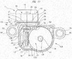
- FIG. 11 in a plan view of the driving apparatus 10 seen along the axis, Ba part of the area occupied by the projecting portion 33 overlaps a part of an area occupied by the worm wheel 41.
- the part of projecting portion 33 which is disposed in the second housing chamber A2 has terminal holding slots 37, 38, and 39, as shown in FIG. 13 .
- the terminal holding slots 37, 38, and 39 are formed by cutting portions of the projecting portion 33 out in a direction along the axis C1. In other words, the terminal holding slots 37, 38, and 39 are cutouts penetrating the projecting portion 33 from its outer surface 33a to inner surface 33b.
- the outer surface 33a is disposed outside the inner surface 33b in the radial direction of a circular plane around the axis B1.
- the terminal holding slot 37 has a center L1 in its length direction
- the terminal holding slot 38 has a center L2 in its length direction
- the terminal holding slot 39 has a center L3 in its length direction.
- the length direction of the terminal holding slots 37, 38, and 39 is parallel with the axis C1.
- the centers L1, L2, and L3 are disposed on substantially the same circumferential line around the axis B1.
- the distance from the axis B1 to the center L1, the distance from the axis B1 to the center L2, and the distance from the axis B1 to the center L3 are substantially the same as each other.
- the terminal 44 is disposed in the terminal holding slot 37
- the terminal 45 is disposed in the terminal holding slot 38
- the terminal 46 is disposed in the terminal holding slot 39.
- the terminals 44, 45, and 46 are disposed at their respective positions different from each other in the direction along the axis C1. Specifically, in the direction along the axis C1, the terminal 45 is disposed between the terminal 44 and the terminal 46. In this manner, in a plan view perpendicular to the axis B1, parts of terminals 44, 45, and 46, respectively supported by the projecting portion 33, are put in stepped arrangement.
- the projecting portion 33 and the terminals 44, 45, and 46 are arranged between the axis B1 and the axis C1 in a direction along the virtual line D1.
- Other structural elements of the driving apparatus 10 of the second embodiment are the same as those of the driving apparatus 10 of the first embodiment.
- the cover 13 is formed with an air hole 78.
- the position of the air hole 78 of the second embodiment is the same as that of the first embodiment.
- the second embodiment of the driving apparatus 10 thus offers the same effect as the first embodiment of the driving apparatus 10 offers.
- heat of the electric components mounted on the control board is transmitted and discharged to the outside of the casing.
- heat of the second housing part is transmitted and discharged to the outside of the casing.
- heat of the electric motor is transmitted to the second housing part through the shaft hole, and then discharged to the outside of the casing.
- the electric motor 16 corresponds to an electric motor of the driving apparatus
- the casing 10A corresponds to a casing of the driving apparatus
- the rotating shaft 27 corresponds to a rotating shaft of the driving apparatus
- the worm 40 corresponds to a worm of the driving apparatus
- the worm gear 42 corresponds to a worm gear of the driving apparatus
- the worm wheel 41 corresponds to a worm wheel of the driving apparatus
- the terminals 44, 45, and 46 correspond to the first terminals of the driving apparatus
- the terminal holder 31 corresponds to a terminal holder of the driving apparatus
- the air hole 78 corresponds to an air hole of the driving apparatus.
- first and second housing chambers A1 and A2 correspond to an inside of a casing of the claimed driving apparatus
- the axis C1 corresponds to an axis of the driving apparatus
- the engaging part E1 corresponds to an engaging part of the driving apparatus.
- the controller chip 53, the capacitors 54 and 55, the inductor 56, and the inverter chip 57 correspond to electric components of the driving apparatus
- the control board 49 corresponds to a control board of the driving apparatus
- the terminals 58, 59, and 60 correspond to second terminals of the driving apparatus.
- the first housing chamber A1 corresponds to a first housing chamber of the driving apparatus
- the second housing chamber A2 corresponds to a second housing chamber of the driving apparatus
- the wall 12B corresponds to a wall of the driving apparatus
- the shaft hale 12C corresponds to a shaft hale of the driving apparatus
- the gear case 12 corresponds to a gear case of the driving apparatus
- the cover 13 corresponds to a cover of the driving apparatus.
- Embodiments of the driving apparatus are not limited to the above embodiments, and the driving apparatus may obviously be modified into various forms on the condition that the modification does not deviate from the substance of the present invention.
- a single air hole but also a plurality of air holes may be formed on the cover.
- the inner peripheral surface of the air hole may be any one of circular, polygonal, and elliptic shapes.
- the position of the air hole is within the area occupied by the control board in the above embodiment.
- the air hole may be disposed in the vicinity of the area occupied by the control board.
- the terminal holding slots 37, 38, and 39 holding the terminals 44, 45, and 46, respectively may be provided as cutouts or insertion recessions. This means that the terminal holder of the driving apparatus has insertion portions which hold the second terminals and in which the first terminals can be inserted.
- the insertion portions include the terminal holding slots 37, 38, and 39 and cutouts or insertion recessions (not shown).
- the number of the first terminals and the number of the second terminals is not limited to 3 but may be 2 or 4 or more.
- the structure in which the second terminals are supported by the projecting portion may include a structure in which the second terminals are fixed to the projecting portion and a structure in which the second terminals can be attached to and detached from the projecting portion.
- the electric motor of the driving apparatus may include a brushless motor and a motor with brushes.
- the motor with brushes has a commutator fixed to the rotating shaft, a brush holder fitted to the motor case, and brushes supported by the brush holder and in contact with the commutator.
- the brush holder carries the second terminals which are connected to the brushes.
- the driving apparatus can be used as, for example, a power source for a motion device incorporated in a vehicle.
- a motion device include a wiper which operates wiper arms, a power window device which operates a window attached to a door, and a power slide door device which operates a door on the side of a vehicle body.
- the driving apparatus applied to the wiper which operates the wiper arms when the driving apparatus is in a specific service environment where the driving apparatus is heated internally and at the same time, cooled externally by rainwater, etc., since a temperature difference between the inside and outside of the driving apparatus tends to become large, the driving apparatus according to the present invention can effectively prevent such a temperature difference.
Landscapes
- Engineering & Computer Science (AREA)
- Power Engineering (AREA)
- Connection Of Motors, Electrical Generators, Mechanical Devices, And The Like (AREA)
- Motor Or Generator Frames (AREA)
Abstract
Description
- The present invention relates to a driving apparatus including a casing in which an electric motor is housed.
- One example of a conventionally-known driving apparatus is disclosed in Patent Document 1, and includes a casing in which an electric motor is housed. In the casing of the driving apparatus disclosed in Patent Document 1, a gear case and a cover are fixed to each other. An electric motor housed in the motor case has a stator and a rotor, and a rotating shaft is provided and rotated together with the rotor. A part of rotating shaft is fitted with a worm, and disposed in the gear case. A worm wheel is disposed in the gear case, and the worm wheel has a gear formed on a circumferential part of the worm wheel. The gear is engaged with the worm.
- Additionally, the cover has an air hole which functions as an element for communicating the inside of the casing with the outside of the casing. The cover is fitted with a breather cap encircling the air hole. The breather cap functions as an element for ventilation through the air hole and for preventing a foreign substance from passing through the air hole. In the driving apparatus disclosed in Patent Document 1, since the inside of the casing and the outside of the casing communicate with each other through the air hole, it is possible to suppress an increase in temperature difference and pressure difference between the inside of the casing and the outside of the casing.
- Patent Document 1: Japanese Patent Application Laid-Open Publication No.
2011-72053 - According to the driving apparatus disclosed in Patent Document 1, in a plan view along an axis serving as a rotation center of the rotating shaft, the air hole is formed at a location which is the farthest from the electric motor in the longitudinal direction of the rotating shaft. This driving apparatus encounters a problem that it is difficult to discharge heat of the electric motor to the outside of the casing.
- An object of the present invention is to provide a driving apparatus which can easily discharge heat of the electric motor to the outside of the casing.
- In a driving apparatus according to one embodiment comprising a casing in which an electric motor is housed, the driving apparatus further comprises: a rotating shaft through which a torque of the electric motor is transmitted, the rotating shaft having an outer peripheral surface formed with a worm; a worm wheel which is disposed in the casing, the worm wheel having a worm gear which is engaged with the worm; a terminal holder which is disposed in the casing, and which supports a first terminal carrying a current to be supplied to the electric motor; and an air hole which extends so as to penetrate the casing, an inside of the casing and an outside of the casing communicating with each other through the air hole, wherein in a plan view perpendicular to an axis serving as a rotation center of the worm wheel, the air hole is disposed in an area defined by projection of an area occupied by the terminal holder in a direction along an axis of the rotating shaft, and between the electric motor and an engaging part of the worm with the worm gear.
- The driving apparatus according to another embodiment further comprises: a control board housed in the casing, electric components for controlling the electric motor are mounted on the control board; and a second terminal mounted on the control board and connected to the first terminal, in the plan view, the air hole is disposed in the vicinity of an area occupied by the control board.
- In the driving apparatus according to another embodiment, the casing includes: a first housing chamber in which the electric motor is housed; and a second housing chamber in which the worm wheel and the control board are housed, the second housing chamber communicates with an outside of the casing through the air hole.
- The driving apparatus according to another embodiment further comprises: a wall disposed in the casing, the wall partitioning an inner space of the casing into the first housing chamber and the second housing chamber; and a shaft hole extending so as to penetrate the wall, the first housing chamber and the second housing chamber communicating with each other through the shaft hole, the rotating shaft being rotatable in the shaft hole.
- In the driving apparatus according to another embodiment, the casing includes: a gear case forming the second housing chamber; and a cover covering an opening of the gear case, the air hole is provided to the cover, and the control board is supported by the cover.
- According to the driving apparatus of one embodiment, since a distance to the air hole from the electric motor in a direction along an axis of the rotating shaft is short, it is possible to easily discharge heat of the electric motor to the outside of the casing.
-
-
FIG. 1 is a sectional view showing a driving apparatus according to the first embodiment; -
FIG. 2 is a bottom view of the driving apparatus ofFIG. 1 ; -
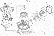
FIG. 3 is an exploded perspective view of the driving apparatus ofFIG. 1 ; -
FIG. 4 is a sectional view of the driving apparatus ofFIG. 1 ; -
FIG. 5 is a bottom view of the driving apparatus ofFIG. 1 with a cover detached from it; -
FIG. 6 is a schematic side view of a control board and a board cover, which are used in the driving apparatus ofFIG. 1 ; -
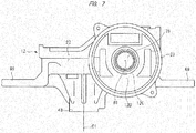
FIG. 7 is a side view of a gear case which is used in the driving apparatus ofFIG. 1 ; -
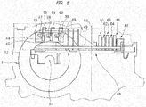
FIG. 8 is a side view of the control board and terminals, which are used in the driving apparatus ofFIG. 1 ; -
FIG. 9 is a bottom view showing the driving apparatus according to the second embodiment; -
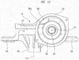
FIG. 10 is a side view of a gear case which is used in the driving apparatus ofFIG. 9 ; -
FIG. 11 is a bottom view of the driving apparatus ofFIG. 9 with a cover detached from it; -
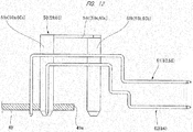
FIG. 12 is a partially-sectional view showing terminals mounted on the control board of the driving apparatus ofFIG. 9 ; and -
FIG. 13 is a sectional view showing the driving apparatus ofFIG. 9 . - Hereinafter, embodiments of the driving apparatus will be described in detail with reference to the drawings.
- Hereinafter, the first embodiment of a driving apparatus will be described in detail with reference to
FIGS. 1 to 8 . Adriving apparatus 10 shown inFIG. 1 is in its completely assembled state. Thedriving apparatus 10 includes acasing 10A. Thecasing 10A has amotor case 11, agear case 12, and acover 13. Themotor case 11 is fixed to thegear case 12, using ascrew 14. Thecover 13 is fixed to thegear case 12, usingscrews 15, and covers an opening 12D of thegear case 12. - The
motor case 11 and thegear case 12 form a first housing chamber A1, and thegear case 12 and thecover 13 form a second housing chamber A2. In other words, the first housing chamber A1 and the second housing chamber A2 are formed in thecasing 10A. In thegear case 12, awall 12B is formed so as to partition an inner space into the first housing chamber A1 and the second housing chamber A2. A shaft hole 12C extends in such a way as to penetrate thewall 12B. The first housing chamber A1 and the second housing chamber A2 communicate with each other through the shaft hole 12C. - The
driving apparatus 10 includes anelectric motor 16 and a speed-reducingmechanism 73. Theelectric motor 16 is disposed in the first housing chamber A1. The speed-reducingmechanism 73 is disposed in the second housing chamber A2. - The
motor case 11 includes acylindrical portion 17 and awall 18 closing a first end of thecylindrical portion 17, the first end being one end in a direction along the axis B1. Themotor case 11 is molded integrally out of insulating material such as synthetic resin. The material of themotor case 11 is not limited to the synthetic resin. Other materials, such as iron, may be used to make themotor case 11 such that an iron sheet is stamped by a press machine to form themotor case 11. Anopening 34 is formed on a second end of thecylindrical portion 17. Thegear case 12 includes abody 22 having arecession 21, and a cylindrical connectingportion 23 continuous with thebody 22. The connectingportion 23 is fixed to thecylindrical portion 17, using ascrew 14. Thegear case 12 is integrally molded out of conductive material such as iron and aluminum. Thewall 12B is formed on the inner surface of the connectingportion 23 along its entire circumference. - The
electric motor 16 has astator 25 and arotor 26. Thestator 25 is disposed in the first housing chamber A1, and does not rotate relative to themotor case 11 and thegear case 12. Thestator 25 has a stator core and a plurality of coils wound around the stator core. The coils include three coils, i.e., "U-phase coil", "V-phase coil", and "W-phase coil". - The
rotor 26 has arotor core 26a and apermanent magnet 28 fixed to the outer peripheral surface of therotor core 26a. Therotor 26 is disposed in such a way as to extend from the housing chamber A1 to the housing chamber A2. A rotatingshaft 27 is disposed in such a way as to extend from the housing chamber A1 to the housing chamber A2, and fitted with two bearings, i.e.,bearings shaft 27. Therotor 26 is fixed to the outer periphery of therotating shaft 27. The torque of therotor 26 is thus transmitted to therotating shaft 27, which causes therotor 26 androtating shaft 27 to rotate together around the axis B1. Bothbearings gear case 12. - A
sleeve 75 is provided and continuous with thegear case 12 and has ashaft hole 76. Theshaft hole 76 has a center aligned with the axis B1, and has abearing 30 fitted in theshaft hole 76. Theshaft hole 76 is connected to the first housing chamber A1 through a shaft hole 12C, and connected to the second housing chamber A2. Astopper 77 is disposed between thesleeve 75 and thewall 12B, and positions thebearing 30 relative to thegear case 12 in a direction along the axis B1. A part ofrotating shaft 27 in its length direction is disposed in the shaft hole 12C. - A
worm 40 is fitted to the outer peripheral surface of one part of therotating shaft 27, and disposed inside therecession 21 of thegear case 12. Apermanent magnet 47 is fitted to the outer peripheral surface of another part ofrotating shaft 27, and disposed inside therecession 21 of thegear case 12. Thepermanent magnet 47 is used as a sensor magnet, and has magnetic poles alternately arranged in a rotation direction of therotating shaft 27. - Furthermore, a
worm wheel 41 is disposed in therecession 21, and aworm gear 42 formed on the outer peripheral surface of theworm wheel 41 is engaged with theworm 40. Anoutput shaft 74 is provided and rotated together with theworm wheel 41. Acylindrical portion 43 is provided and continuous with thegear case 12, and theoutput shaft 74 is rotatably fitted in thecylindrical portion 43. InFIG. 1 which is a front view of the drivingapparatus 10 seen in a direction parallel with the axis B1, the rotatingshaft 27 and the axis B1 are disposed between thecover 13 and thecylindrical portion 43. Theoutput shaft 74 extends from the second housing chamber A2 to come out of thecasing 10A. Theworm 40 and theworm gear 42 collectively constitute the speed-reducingmechanism 73. An axis C1 is a rotation center of theoutput shaft 74, and does not intersect with the axis B1. InFIG. 1 which is the front view of the drivingapparatus 10 seen in the direction parallel with the axis B1, the axis B1 and axis C1 are at right angles with each other. - On the other hand, a
terminal holder 31 is disposed in the connectingportion 23. Theterminal holder 31 is integrally molded out of synthetic resin, and has acylindrical portion 32 and a projectingportion 33 formed on a part of thecylindrical portion 32 in its circumferential direction. As shown inFIG. 6 , in a plan view perpendicular to the axis B1, the projectingportion 33 is rectangular and disposed in a direction along a tangent to the inner circumference of the connectingportion 23. - As shown in
FIGS. 1 and7 , a through-hole 36 extends so as to penetrate thewall 12B. Through the through-hole 36, the first housing chamber A1 communicates with the second housing chamber A2. In a plan view perpendicular to the axis B1, through-hole 36 is disposed outside the shaft hole 12C. The through-hole 36 has aninner wall 36a. - With the
terminal holder 31 fitted in the connectingportion 23, the projectingportion 33 projects into the second housing chamber A2 through the through-hole 36, as shown inFIG. 1 . The projectingportion 33 is in contact with theinner wall 36a. The part of projectingportion 33 which is disposed in the second housing chamber A2 hasterminal holding slots FIG. 6 . Theterminal holding slots portion 33 out in a direction along the axis C1. - Furthermore, a terminal 44 is provided in the
terminal holding slot 37, a terminal 45 is provided in theterminal holding slot 38, and a terminal 46 is provided in theterminal holding slot 39. Theterminals terminals - As shown in
FIGS. 1 and5 , aboard cover 48 and acontrol board 49 are disposed in the second housing chamber A2. Theboard cover 48 is integrally molded of insulating material such as synthetic resin, into a plate-like shape. Theboard cover 48 has a plurality of lockingclaws 50. Thecover 13 has a plurality of locking portions formed on its inner surface. The lockingclaws 50 are respectively locked onto the locking portions. This fixes theboard cover 48 to thecover 13. - The
control board 49 is disposed between thecover 13 and theboard cover 48 in a direction along the axis C1. InFIGS. 2 and5 which are bottom views of the drivingapparatus 10, thecontrol board 49 is substantially rectangular. Thecontrol board 49 is positioned and fixed to thecover 13, using a plurality of positioning screws 52. This sets thecontrol board 49 at right angles with the axis C1, as shown inFIG. 6 . - The
control board 49 is molded out of insulating material, and carries an electric circuit as well as various electric components. The electric components mounted on thecontrol board 49 include acontroller chip 53,capacitors inductor 56, aninverter chip 57 having a plurality of switching elements,terminals terminals 61 to 65, aground terminal 66, andmagnetic sensors 68. The threemagnetic sensors 68 are Hall ICs which detect the intensity and switching of a magnetic field generated by thepermanent magnet 47 and output an electric signal. - As shown in
FIG. 2 , thecover 13 has aconnector 67. First ends of theterminals 61 to 65 are disposed in theconnector 67, and second ends of theterminals 61 to 65 are connected to the electric circuit of thecontrol board 49. A socket for a power cord connected to an external power supply is connected to theconnector 67. Theground terminal 66 connects the electric circuit to thegear case 12. Next, theterminals FIG. 8 . Theterminals leg portions portion 58c connecting theleg portion 58a to theleg portion 58b. Theleg portion 58a has one end fixed to thecontrol board 49, and the other end connected to the connectingportion 58c. - The terminal 59 has
leg portions portion 59c connecting theleg portion 59a to theleg portion 59b. Theleg portion 59a has one end fixed to thecontrol board 49, and the other end connected to the connectingportion 59c. The terminal 60 hasleg portions portion 60c connecting theleg portion 60a to theleg portion 60b. Theleg portion 60a has one end fixed to thecontrol board 49, and the other end connected to the connectingportion 60c. All of theleg portions control board 49, that is, extend in a direction along the axis C1. - Furthermore, in
FIG. 5 which is a plan view of the drivingapparatus 10, theleg portions edge 49a of thecontrol board 49. Theleg portion 58b of the terminal 58 is disposed in theterminal holding slot 37, and connected to the terminal 44 supported by the projectingportion 33. Theleg portion 59b of the terminal 59 is disposed in theterminal holding slot 38, and connected to the terminal 45 supported by the projectingportion 33. Theleg portion 60b of the terminal 60 is disposed in theterminal holding slot 39 and is connected to the terminal 46 supported by the projectingportion 33. - The
gear case 12 has a plurality ofmounts 69 overhanging from its outer peripheral surface, and anannular bush 71 is fitted in a hole of eachmount 69. Thebush 71 is integrally molded out of rubber-like elastic material. Eachbush 71 has ahole 72 in which a screw is screwed to mount the drivingapparatus 10 to a vehicle body frame or a bracket. - Next, a ventilating mechanism for causing the second housing chamber A2 to communicate with the outside of the
casing 10A will then be described. Thecover 13 has anair hole 78 extending so as to penetrate thecover 13 in the direction of the axis C1. InFIG. 2 which is a plan view perpendicular to the axis C1, the location of theair hole 78 is defined as follows. Theair hole 78 is disposed in an area defined by projection of an area occupied by the projectingportion 33 of theterminal holder 31 in a direction along the axis B1, and which is an area between theelectric motor 16 and an engaging part E1 where theworm 40 and theworm gear 42 are engaged with each other. The engaging part E1 is disposed substantially in the center of an area occupied by thecontrol board 49 in the direction along the axis B1. - More specifically, in
FIG. 2 which is a bottom view of the drivingapparatus 10, theair hole 78 is disposed between the position of thepermanent magnet 47 and theworm gear 42. The position of theair hole 78 in the direction along the axis B1 is close to the area occupied by thepermanent magnet 47. The position of theair hole 78 is within the area occupied by thecontrol board 49. Specifically, the position of theair hole 78 is within the half of area occupied by thecontrol board 49 which is closer to therotating shaft 27 in the longitudinal direction of thecontrol board 49. - The
cover 13 may be provided with a breather plug encircling theair hole 78. The breather plug is a mechanism which opens and closes in response to a change in the internal pressure of the second housing chamber A2. This mechanism is known to the public through its disclosure in for example, Japanese Unexamined Patent Application Publication No.2011-72053 cover 13 is fitted also with a filter which covers theair hole 78. The filter is an element which allows air passage while blocking a foreign substance. - The operation and control of the driving
apparatus 10 will then be described. Power is supplied from the external power supply to the electric circuit of thecontrol board 49 through theterminals 61 to 65. As a result, the switching elements of theinverter chip 57 are switched on and off to cause current to flow through the three coils in order, which generates a rotating magnetic field, thus causing therotor 26 androtating shaft 27 to rotate together. Power supplied from the external power supply is channeled through theterminals terminals controller chip 53 detects the rotation position of therotating shaft 27, based on a signal from themagnetic sensor 68, and controls timing of switching on and off the switching elements and the ratio of switching on the switching elements, thereby controls the number of revolutions, i.e., rotating speed of therotating shaft 27. - In this manner, the
electric motor 16 has a structure in which current flowing through the coils of thestator 25 causes thestator 25 to interact with thepermanent magnet 28 of therotor core 26a, thus generating a rotating magnetic field. This structure does not include a brush and a commutator. Theelectric motor 16 is, therefore, a brushless motor. - Incidentally, the
electric motor 16 generates heat when carrying a current. This current also causes theterminals 44 to 46 andterminals 58 to 65, which are electric components mounted on thecontrol board 49, to generate heat. As a result, the temperature of the first housing chamber A1 as well as the temperature of the second housing chamber A2 rises. Heat from the first housing chamber A1 is discharged through the shaft holes 12C and 76 to the second housing chamber A2. In the first housing chamber A1 and second housing chamber A2, air expands as their temperatures rise, causing the internal pressure to increase. - When a temperature difference arises between the first housing chamber A1 and second housing chamber A2 and the outside of the
casing 10A, heat from the first housing chamber A1 and second housing chamber A2 flows through theair hole 78 to be discharged to the outside of thecasing 10A. This process suppresses a rise in the temperatures of the first housing chamber A1 and second housing chamber A2. When a pressure difference arises between the interior of the first housing chamber A1 and second housing chamber A2 and the outside of thecasing 10A, on the other hand, theair hole 78 communicatively connecting the interior of the first housing chamber A1 and second housing chamber A2 to the outside of thecasing 10A also works to let air escape, thus suppressing an increase in the internal pressures of the first housing chamber A1 and second housing chamber A2. - In this manner, the
air hole 78 plays a role of suppressing a rise in the temperatures of the first housing chamber A1 and second housing chamber A2 as well as a role of suppressing an increase in the internal pressures of the first housing chamber A1 and second housing chamber A2. As shown inFIG. 2 , theair hole 78 is disposed between the area occupied by theelectric motor 16 and the engaging part E1 in the direction along the axis B1. Therefore, when heat from the first housing chamber A1 is transmitted through the shaft holes 12C and 76 to the second housing chamber A2, this heat flows through theair hole 78 to come out of thecasing 10A, thus failing to spread across the entire area occupied by thecontrol board 49 in the direction along the axis B1. Theair hole 78 is disposed closer to thecontrol board 49 than the shaft holes 12C and 76. As a result, heat generated from the terminals mounted on thecontrol board 49 in the second housing chamber A2 tends to flow through theair hole 78 and come out of thecasing 10A before reaching the first housing chamber A1. Hence heat from theelectric motor 16 is readily released to the outside of thecasing 10A. - Hereinafter, the second embodiment of a driving apparatus will be described in detail with reference to
FIGS. 9 to 13 . The projectingportion 33 provided to theterminal holder 31 and theterminals 58 to 60 in the second embodiment of the driving apparatus differ in shape and structure from those of the first embodiment of the driving apparatus. - As shown in
FIG. 10 , anannular recession 35 is formed in the connectingportion 23, and thecylindrical portion 32 of theterminal holder 31 is disposed in therecession 35. Thegear case 12 has the through-hole 36 connecting therecession 35 of the connectingportion 23 to the second housing chamber A2. The projectingportion 33 is formed in an area defined by a predetermined interior angle along the circumference around the axis B1. The projectingportion 33 is formed into, for example, an arcuate shape disposed in an area with an interior angle smaller than 90 degrees, and has a predetermined thickness in the radial direction of a circular plane around the axis B1. As shown inFIG. 11 , in a plan view of the drivingapparatus 10 seen along the axis, Ba part of the area occupied by the projectingportion 33 overlaps a part of an area occupied by theworm wheel 41. - With the
terminal holder 31 fitted in therecession 35, the front end of the projectingportion 33 is disposed in the second housing chamber A2, as shown inFIG. 11 . The part of projectingportion 33 which is disposed in the second housing chamber A2 hasterminal holding slots FIG. 13 . Theterminal holding slots portion 33 out in a direction along the axis C1. In other words, theterminal holding slots portion 33 from itsouter surface 33a toinner surface 33b. Theouter surface 33a is disposed outside theinner surface 33b in the radial direction of a circular plane around the axis B1. Theterminal holding slot 37 has a center L1 in its length direction, theterminal holding slot 38 has a center L2 in its length direction, and theterminal holding slot 39 has a center L3 in its length direction. The length direction of theterminal holding slots - Additionally, as shown in
FIG. 13 , the centers L1, L2, and L3 are disposed on substantially the same circumferential line around the axis B1. In other words, the distance from the axis B1 to the center L1, the distance from the axis B1 to the center L2, and the distance from the axis B1 to the center L3 are substantially the same as each other. The terminal 44 is disposed in theterminal holding slot 37, the terminal 45 is disposed in theterminal holding slot 38, and the terminal 46 is disposed in theterminal holding slot 39. - Furthermore, the
terminals terminals portion 33, are put in stepped arrangement. - As shown in
FIG. 13 , under the condition that a virtual line D1 making a right angle with the axis C1 and crossing the axis B1, the projectingportion 33 and theterminals apparatus 10 of the second embodiment are the same as those of the drivingapparatus 10 of the first embodiment. - Also in the second embodiment of the driving
apparatus 10, as shown inFIG. 9 , thecover 13 is formed with anair hole 78. The position of theair hole 78 of the second embodiment is the same as that of the first embodiment. The second embodiment of the drivingapparatus 10 thus offers the same effect as the first embodiment of the drivingapparatus 10 offers. - According to another embodiment of the driving apparatus, heat of the electric components mounted on the control board is transmitted and discharged to the outside of the casing.
- According to another embodiment of the driving apparatus, heat of the second housing part is transmitted and discharged to the outside of the casing.
- According to another embodiment of the driving apparatus, heat of the electric motor is transmitted to the second housing part through the shaft hole, and then discharged to the outside of the casing.
- The corresponding relationship between the configurations of the first and second embodiments and the configuration of the claimed driving apparatus will then be described. The
electric motor 16 corresponds to an electric motor of the driving apparatus, thecasing 10A corresponds to a casing of the driving apparatus, the rotatingshaft 27 corresponds to a rotating shaft of the driving apparatus, theworm 40 corresponds to a worm of the driving apparatus, theworm gear 42 corresponds to a worm gear of the driving apparatus, theworm wheel 41 corresponds to a worm wheel of the driving apparatus, theterminals terminal holder 31 corresponds to a terminal holder of the driving apparatus, and theair hole 78 corresponds to an air hole of the driving apparatus. - Furthermore, the first and second housing chambers A1 and A2 correspond to an inside of a casing of the claimed driving apparatus, the axis C1 corresponds to an axis of the driving apparatus, the engaging part E1 corresponds to an engaging part of the driving apparatus. The
controller chip 53, thecapacitors inductor 56, and theinverter chip 57 correspond to electric components of the driving apparatus, thecontrol board 49 corresponds to a control board of the driving apparatus, theterminals wall 12B corresponds to a wall of the driving apparatus, the shaft hale 12C corresponds to a shaft hale of the driving apparatus, thegear case 12 corresponds to a gear case of the driving apparatus, and thecover 13 corresponds to a cover of the driving apparatus. - Embodiments of the driving apparatus are not limited to the above embodiments, and the driving apparatus may obviously be modified into various forms on the condition that the modification does not deviate from the substance of the present invention. For example, not only a single air hole but also a plurality of air holes may be formed on the cover. In a bottom view of the cover, the inner peripheral surface of the air hole may be any one of circular, polygonal, and elliptic shapes. Furthermore, the position of the air hole is within the area occupied by the control board in the above embodiment. The air hole, however, may be disposed in the vicinity of the area occupied by the control board. Furthermore, the
terminal holding slots terminals terminal holding slots - The number of the first terminals and the number of the second terminals is not limited to 3 but may be 2 or 4 or more. The structure in which the second terminals are supported by the projecting portion may include a structure in which the second terminals are fixed to the projecting portion and a structure in which the second terminals can be attached to and detached from the projecting portion.
- Furthermore, the electric motor of the driving apparatus may include a brushless motor and a motor with brushes. The motor with brushes has a commutator fixed to the rotating shaft, a brush holder fitted to the motor case, and brushes supported by the brush holder and in contact with the commutator. The brush holder carries the second terminals which are connected to the brushes.
- The driving apparatus can be used as, for example, a power source for a motion device incorporated in a vehicle. Such a motion device include a wiper which operates wiper arms, a power window device which operates a window attached to a door, and a power slide door device which operates a door on the side of a vehicle body. Specifically, in the driving apparatus applied to the wiper which operates the wiper arms, when the driving apparatus is in a specific service environment where the driving apparatus is heated internally and at the same time, cooled externally by rainwater, etc., since a temperature difference between the inside and outside of the driving apparatus tends to become large, the driving apparatus according to the present invention can effectively prevent such a temperature difference.
Claims (5)
- A driving apparatus comprising a casing in which an electric motor is housed, the driving apparatus further comprising:a rotating shaft through which a torque of the electric motor is transmitted, the rotating shaft having an outer peripheral surface formed with a worm;a worm wheel which is disposed in the casing, the worm wheel having a worm gear which is engaged with the worm;a terminal holder which is disposed in the casing, and which supports a first terminal carrying a current to be supplied to the electric motor; andan air hole which extends so as to penetrate the casing, an inside of the casing and an outside of the casing communicating with each other through the air hole,wherein in a plan view perpendicular to an axis serving as a rotation center of the worm wheel, the air hole is disposed in an area defined by projection of an area occupied by the terminal holder in a direction along an axis of the rotating shaft, and between the electric motor and an engaging part of the worm with the worm gear.
- The driving apparatus according to claim 1, further comprising:a control board housed in the casing, electric components for controlling the electric motor are mounted on the control board; anda second terminal mounted on the control board and connected to the first terminal, whereinin the plan view, the air hole is disposed in the vicinity of an area occupied by the control board.
- The driving apparatus according to claim 2, wherein
the casing includes:a first housing chamber in which the electric motor is housed; anda second housing chamber in which the worm wheel and the control board are housed,the second housing chamber communicates with an outside of the casing through the air hole. - The driving apparatus according to claim 3, further comprising:a wall disposed in the casing, the wall partitioning an inner space of the casing into the first housing chamber and the second housing chamber; anda shaft hole extending so as to penetrate the wall, the first housing chamber and the second housing chamber communicating with each other through the shaft hole, the rotating shaft being rotatable in the shaft hole.
- The driving apparatus according to claim 3, wherein
the casing includes:a gear case forming the second housing chamber; anda cover covering an opening of the gear case,the air hole is provided to the cover, andthe control board is supported by the cover.
Applications Claiming Priority (2)
| Application Number | Priority Date | Filing Date | Title |
|---|---|---|---|
| JP2014218056A JP6462313B2 (en) | 2014-10-27 | 2014-10-27 | Drive device |
| PCT/JP2015/080099 WO2016068073A1 (en) | 2014-10-27 | 2015-10-26 | Drive device |
Publications (2)
| Publication Number | Publication Date |
|---|---|
| EP3214737A1 true EP3214737A1 (en) | 2017-09-06 |
| EP3214737A4 EP3214737A4 (en) | 2018-05-30 |
Family
ID=55857412
Family Applications (1)
| Application Number | Title | Priority Date | Filing Date |
|---|---|---|---|
| EP15855663.9A Withdrawn EP3214737A4 (en) | 2014-10-27 | 2015-10-26 | Drive device |
Country Status (5)
| Country | Link |
|---|---|
| US (1) | US10411559B2 (en) |
| EP (1) | EP3214737A4 (en) |
| JP (1) | JP6462313B2 (en) |
| CN (1) | CN107078598A (en) |
| WO (1) | WO2016068073A1 (en) |
Families Citing this family (13)
| Publication number | Priority date | Publication date | Assignee | Title |
|---|---|---|---|---|
| JP6431774B2 (en) * | 2015-01-19 | 2018-11-28 | 株式会社ミツバ | Drive device |
| JP6664878B2 (en) * | 2015-02-17 | 2020-03-13 | 株式会社ミツバ | Motor device and wiper device |
| TR201806877A2 (en) * | 2018-05-15 | 2018-06-21 | Ikizler Kalip Pres Sanayi Ve Ticaret Ltd Sirketi | Smart, Monoblock And Compact Motor Gear Reducer |
| JP7051101B2 (en) * | 2018-10-26 | 2022-04-11 | 株式会社不二工機 | Flow switching valve |
| JP2020137207A (en) * | 2019-02-15 | 2020-08-31 | 日本電産株式会社 | Motor unit |
| DE102019203525A1 (en) * | 2019-03-15 | 2020-09-17 | Brose Fahrzeugteile SE & Co. Kommanditgesellschaft, Würzburg | Drive device with a brushless electric motor |
| US10886866B1 (en) * | 2019-07-01 | 2021-01-05 | Nidec Motor Corporation | Motor controller with inductor mounted transverse to control board |
| JP7340399B2 (en) * | 2019-09-30 | 2023-09-07 | 株式会社ミツバ | Motor with reducer |
| JP7415749B2 (en) * | 2020-03-31 | 2024-01-17 | ニデック株式会社 | drive device |
| EP4305737B1 (en) * | 2021-05-05 | 2026-02-25 | Brose Fahrzeugteile SE & Co. Kommanditgesellschaft, Bamberg | Drive device having a brushless electric motor |
| DE102021211846A1 (en) | 2021-10-20 | 2023-04-20 | Brose Fahrzeugteile Se & Co. Kommanditgesellschaft, Bamberg | Driving device with a brushless electric motor |
| US12573915B2 (en) | 2021-06-23 | 2026-03-10 | Mitsuba Corporation | Motor with deceleration mechanism |
| US12101015B2 (en) * | 2022-01-19 | 2024-09-24 | Shenzhen FeiYida Motor Limited Company | High-speed motor and assembling method thereof |
Family Cites Families (13)
| Publication number | Priority date | Publication date | Assignee | Title |
|---|---|---|---|---|
| JPS59169472U (en) * | 1983-04-28 | 1984-11-13 | 日産自動車株式会社 | Breather structure of electrical components |
| JPH056215Y2 (en) * | 1987-06-12 | 1993-02-17 | ||
| FR2755313B1 (en) * | 1996-02-15 | 1999-07-09 | Mitsuba Corp | SPEED REDUCING MOTOR |
| JPH10252621A (en) * | 1997-03-07 | 1998-09-22 | Mitsuba Corp | Drainage structure of engine starter |
| JP2001061257A (en) | 1999-08-23 | 2001-03-06 | Asmo Co Ltd | Motor with cooling fan |
| EP1099608B1 (en) * | 1999-11-11 | 2009-03-04 | Mitsuba Corporation | Water-drop proof structure for wiper motor apparatus |
| JP3705425B2 (en) | 2000-03-30 | 2005-10-12 | アスモ株式会社 | Geared motor |
| JP4906376B2 (en) * | 2006-03-20 | 2012-03-28 | 株式会社ミツバ | Motor equipment |
| JP2009112139A (en) | 2007-10-31 | 2009-05-21 | Mitsuba Corp | Brushless motor |
| JP2009124928A (en) * | 2007-11-19 | 2009-06-04 | Asmo Co Ltd | Motor |
| JP5507170B2 (en) | 2009-09-23 | 2014-05-28 | 株式会社ミツバ | Electric motor with reduction gear |
| JP2014027801A (en) | 2012-07-27 | 2014-02-06 | Asmo Co Ltd | Motor with speed reducer and method of manufacturing motor with speed reducer |
| JP6293476B2 (en) * | 2013-04-22 | 2018-03-14 | アスモ株式会社 | motor |
-
2014
- 2014-10-27 JP JP2014218056A patent/JP6462313B2/en not_active Expired - Fee Related
-
2015
- 2015-10-26 CN CN201580058340.2A patent/CN107078598A/en active Pending
- 2015-10-26 EP EP15855663.9A patent/EP3214737A4/en not_active Withdrawn
- 2015-10-26 WO PCT/JP2015/080099 patent/WO2016068073A1/en not_active Ceased
- 2015-10-26 US US15/522,093 patent/US10411559B2/en not_active Expired - Fee Related
Also Published As
| Publication number | Publication date |
|---|---|
| EP3214737A4 (en) | 2018-05-30 |
| US20170366070A1 (en) | 2017-12-21 |
| CN107078598A (en) | 2017-08-18 |
| WO2016068073A1 (en) | 2016-05-06 |
| JP2016086539A (en) | 2016-05-19 |
| JP6462313B2 (en) | 2019-01-30 |
| US10411559B2 (en) | 2019-09-10 |
Similar Documents
| Publication | Publication Date | Title |
|---|---|---|
| US10411559B2 (en) | Driving apparatus | |
| EP3249787B1 (en) | Drive device | |
| CN105682402B (en) | Receiver member and driving device including the receiver member | |
| US20180375400A1 (en) | Electric motor for a fluid pump, modular motor family for forming different fluid pumps with several of such electric motors, and production method | |
| CN106329797B (en) | Drive device | |
| US9537367B2 (en) | Driving device | |
| CN102044934B (en) | Motor drive component | |
| KR20190066899A (en) | A cooling fan | |
| WO2019004004A1 (en) | Electronic device | |
| JP6070311B2 (en) | Electric oil pump device | |
| RU2020107403A (en) | ELECTRIC MOTOR INTEGRATED INTO A WHEEL, EQUIPPED WITH INVERTER, AND METHOD FOR PRODUCING SUCH ELECTRIC MOTOR INTEGRATED INTO A WHEEL | |
| JP6012022B2 (en) | Brushless motor | |
| CN106899096B (en) | Electric machine | |
| JPWO2015166571A1 (en) | Vehicle control device | |
| WO2017141637A1 (en) | Drive device | |
| JP2014009676A (en) | Motor-driven oil pump device | |
| WO2017022007A1 (en) | Dynamo electric machine unit | |
| KR20160097589A (en) | Electric water pump with filter assembly | |
| EP3214738B1 (en) | Drive device | |
| KR101965010B1 (en) | Motor and method for manufacturing motor | |
| CN105322693B (en) | Brushless motor | |
| JP2015031253A (en) | Blower device |
Legal Events
| Date | Code | Title | Description |
|---|---|---|---|
| STAA | Information on the status of an ep patent application or granted ep patent |
Free format text: STATUS: THE INTERNATIONAL PUBLICATION HAS BEEN MADE |
|
| PUAI | Public reference made under article 153(3) epc to a published international application that has entered the european phase |
Free format text: ORIGINAL CODE: 0009012 |
|
| STAA | Information on the status of an ep patent application or granted ep patent |
Free format text: STATUS: REQUEST FOR EXAMINATION WAS MADE |
|
| 17P | Request for examination filed |
Effective date: 20170529 |
|
| AK | Designated contracting states |
Kind code of ref document: A1 Designated state(s): AL AT BE BG CH CY CZ DE DK EE ES FI FR GB GR HR HU IE IS IT LI LT LU LV MC MK MT NL NO PL PT RO RS SE SI SK SM TR |
|
| AX | Request for extension of the european patent |
Extension state: BA ME |
|
| DAV | Request for validation of the european patent (deleted) | ||
| DAX | Request for extension of the european patent (deleted) | ||
| RIC1 | Information provided on ipc code assigned before grant |
Ipc: H02K 5/04 20060101ALI20180419BHEP Ipc: H02K 11/33 20160101ALN20180419BHEP Ipc: H02K 9/02 20060101ALI20180419BHEP Ipc: H02K 7/116 20060101AFI20180419BHEP |
|
| A4 | Supplementary search report drawn up and despatched |
Effective date: 20180426 |
|
| STAA | Information on the status of an ep patent application or granted ep patent |
Free format text: STATUS: EXAMINATION IS IN PROGRESS |
|
| 17Q | First examination report despatched |
Effective date: 20181211 |
|
| STAA | Information on the status of an ep patent application or granted ep patent |
Free format text: STATUS: THE APPLICATION IS DEEMED TO BE WITHDRAWN |
|
| 18D | Application deemed to be withdrawn |
Effective date: 20191127 |