EP3214502A1 - Fixing device capable of setting position of claw member in accordance with kind of sheet, and image forming apparatus including the same - Google Patents
Fixing device capable of setting position of claw member in accordance with kind of sheet, and image forming apparatus including the same Download PDFInfo
- Publication number
- EP3214502A1 EP3214502A1 EP17158387.5A EP17158387A EP3214502A1 EP 3214502 A1 EP3214502 A1 EP 3214502A1 EP 17158387 A EP17158387 A EP 17158387A EP 3214502 A1 EP3214502 A1 EP 3214502A1
- Authority
- EP
- European Patent Office
- Prior art keywords
- fixing
- sheet
- claw
- claw member
- sliding
- Prior art date
- Legal status (The legal status is an assumption and is not a legal conclusion. Google has not performed a legal analysis and makes no representation as to the accuracy of the status listed.)
- Granted
Links
- 210000000078 claw Anatomy 0.000 title claims abstract description 89
- 238000000926 separation method Methods 0.000 claims description 46
- 238000000034 method Methods 0.000 description 25
- 230000002093 peripheral effect Effects 0.000 description 17
- 230000015572 biosynthetic process Effects 0.000 description 10
- 238000005755 formation reaction Methods 0.000 description 10
- 108091008695 photoreceptors Proteins 0.000 description 6
- XEEYBQQBJWHFJM-UHFFFAOYSA-N Iron Chemical compound [Fe] XEEYBQQBJWHFJM-UHFFFAOYSA-N 0.000 description 4
- 238000007599 discharging Methods 0.000 description 4
- 229910052751 metal Inorganic materials 0.000 description 4
- 239000002184 metal Substances 0.000 description 4
- 238000011144 upstream manufacturing Methods 0.000 description 4
- 238000004804 winding Methods 0.000 description 4
- 238000003825 pressing Methods 0.000 description 3
- 238000005299 abrasion Methods 0.000 description 2
- 229910052782 aluminium Inorganic materials 0.000 description 2
- XAGFODPZIPBFFR-UHFFFAOYSA-N aluminium Chemical compound [Al] XAGFODPZIPBFFR-UHFFFAOYSA-N 0.000 description 2
- 238000004140 cleaning Methods 0.000 description 2
- 239000011162 core material Substances 0.000 description 2
- 230000000994 depressogenic effect Effects 0.000 description 2
- 229910052742 iron Inorganic materials 0.000 description 2
- 238000010030 laminating Methods 0.000 description 2
- 239000000463 material Substances 0.000 description 2
- 230000001154 acute effect Effects 0.000 description 1
- 239000000919 ceramic Substances 0.000 description 1
- 239000011248 coating agent Substances 0.000 description 1
- 238000000576 coating method Methods 0.000 description 1
- 238000010586 diagram Methods 0.000 description 1
- 238000006073 displacement reaction Methods 0.000 description 1
- 229910052736 halogen Inorganic materials 0.000 description 1
- 150000002367 halogens Chemical class 0.000 description 1
- 239000000155 melt Substances 0.000 description 1
- 229920002379 silicone rubber Polymers 0.000 description 1
Images



Classifications
-
- G—PHYSICS
- G03—PHOTOGRAPHY; CINEMATOGRAPHY; ANALOGOUS TECHNIQUES USING WAVES OTHER THAN OPTICAL WAVES; ELECTROGRAPHY; HOLOGRAPHY
- G03G—ELECTROGRAPHY; ELECTROPHOTOGRAPHY; MAGNETOGRAPHY
- G03G15/00—Apparatus for electrographic processes using a charge pattern
- G03G15/20—Apparatus for electrographic processes using a charge pattern for fixing, e.g. by using heat
- G03G15/2003—Apparatus for electrographic processes using a charge pattern for fixing, e.g. by using heat using heat
- G03G15/2014—Apparatus for electrographic processes using a charge pattern for fixing, e.g. by using heat using heat using contact heat
- G03G15/2017—Structural details of the fixing unit in general, e.g. cooling means, heat shielding means
- G03G15/2028—Structural details of the fixing unit in general, e.g. cooling means, heat shielding means with means for handling the copy material in the fixing nip, e.g. introduction guides, stripping means
Definitions
- This invention relates to a fixing device and an image forming apparatus including the fixing device.
- a typical image forming apparatus using an electrophotographic method includes a fixing device including a pressure roller that is brought into pressure contact with a fixing roller.
- the fixing device applies pressure and heats to sheets passing between both rollers (through a fixing nip) to fix toner images on the sheets (fixing process).
- the sheet enters the fixing nip while the surface on which the toner image is transferred is opposed to the fixing roller side.
- the fixing device includes a separation claw constantly contacting a surface of the fixing roller.
- This separation claw prevents the sheet after a fixing process from being wound around the fixing roller.
- the separation claw constantly contacts (slidably contact) the fixing roller, and this causes a problem that the fixing roller is easily abraded.
- a fixing device including a mechanism (solenoid) that causes a separation claw to contact and be separated from a fixing roller. This mechanism is controlled such that the separation claw contacts the fixing roller only when the fixing process is performed.
- a fixing device includes a fixing member, a pressure member, and a separating unit.
- the fixing member is rotatably located.
- the fixing member is heated or heatable by a heat source.
- the pressure member is rotatably located.
- the pressure member is in a pressure contact or bringable in a pressure contact with the fixing member to form a fixing nip.
- the separating unit is configured to separate a sheet from the fixing member.
- the sheet is attached on the fixing member when passing through the fixing nip.
- the separating unit includes a sliding member, a claw member, and a turning mechanism.
- the sliding member is located in a state of contacting a surface of the fixing member.
- the claw member runs toward the fixing nip from the sliding member.
- the claw member has a distal end portion.
- the claw member is located in a state where the distal end portion contacts the surface of the fixing member.
- the turning mechanism reciprocates the sliding member and the claw member along a rotation direction of the
- FIGS. 1 , 3 , 5 , and 7 paper-surface-front sides in FIGS. 1 , 3 , 5 , and 7 are defined as a front surface, and the preferred embodiment of the invention is described using directions indicated in the respective drawings as a reference.
- a term of "conveyance direction” means a conveyance direction of a sheet S.
- upstream,” “downstream,” and terms similar to these mean an "upstream” and a “downstream” of the conveyance direction, and a concept similar to these.
- FIG. 1 schematically illustrates a cross section of an internal structure of the multi-functional peripheral 1.
- the multi-functional peripheral 1 includes a printing device 1A and a scanning device 1B.
- the printing device 1A forms images on the sheet S using an electrophotographic method.
- the scanning device 1B includes components (not illustrated) that optically read image information of an original document.
- the scanning device 1B is located above the printing device 1A across an in-barrel space 1C.
- the scanning device 1B has a known structure, and thus the following omits the detailed description.
- the printing device 1A includes an apparatus main body 2, a sheet feed cassette 3, and a sheet discharge tray 4.
- the sheet feed cassette 3 is located in a lower portion of the apparatus main body 2 and is removably attachable in a front-rear direction.
- the sheet feed cassette 3 houses paper (a bundle of) sheets S.
- the sheet discharge tray 4 is located on a top surface of the apparatus main body 2 (a bottom surface of the in-barrel space 1C).
- a main conveyance path 5 and an inverting conveyance path 6 are formed inside the apparatus main body 2.
- the main conveyance path 5 vertically runs from the sheet feed cassette 3 to the sheet discharge tray 4.
- the inverting conveyance path 6 vertically runs so as to communicate between an upstream portion and a downstream portion of the main conveyance path 5.
- the printing device 1A includes a paper sheet feeder 10, an image forming unit 11, a fixing device 12, a discharging roller pair 13, and a control device 14.
- the paper sheet feeder 10 is located in an upstream end portion of the main conveyance path 5.
- the paper sheet feeder 10 conveys the sheets S from the sheet feed cassette 3 one by one to the main conveyance path 5.
- the image forming unit 11 and the fixing device 12 are located in an intermediate portion of the main conveyance path 5.
- the discharging roller pair 13 is located on a downstream end portion of the main conveyance path 5.
- the control device 14 (control unit) integrally controls operations of the multi-functional peripheral 1.
- the image forming unit 11 transfers a toner image on the sheet S.
- the image forming unit 11 includes a toner container 20, a drum unit 21, and a light scanning device 22.
- the toner container 20 houses, for example, a black toner (developer).
- the drum unit 21 includes a photoreceptor drum 23, a charging apparatus 24, a developing device 25, a transfer roller 26, and a cleaning apparatus 27.
- the charging apparatus 24, the developing device 25, the transfer roller 26, and the cleaning apparatus 27 are located in a peripheral area of the photoreceptor drum 23 in order of the transfer process.
- the transfer roller 26 is brought into pressure contact with the photoreceptor drum 23 from a lower side to form a transfer nip 26a.
- the fixing device 12 includes a pressure roller 32 that is brought into pressure contact with a fixing roller 31 to form a fixing nip N.
- the fixing device 12 heats the sheet S passing through the fixing nip N to fix the toner image on the sheet S while applying pressure.
- the control device 14 performs an image formation process based on, for example, image data read by the scanning device 1B as follows.
- the charging apparatus 24 charges a surface of the photoreceptor drum 23.
- the light scanning device 22 performs exposure (see the dashed line arrow in FIG. 1 ) in accordance with the image data on the photoreceptor drum 23.
- the developing device 25 develops an electrostatic latent image on the photoreceptor drum 23 into the toner image.
- the sheet S is transmitted to the main conveyance path 5 from the paper sheet feeder 10.
- the toner image is transferred on a surface of the sheet S passing through the transfer nip 26a.
- the fixing device 12 fixes the toner image on the surface of the sheet S. After a fixing process, the sheet S is discharged on the sheet discharge tray 4 by the discharging roller pair 13.
- the sheet S is reversely conveyed by the discharging roller pair 13 to be conveyed to the inverting conveyance path 6 after the fixing process. After that, similarly to the above, the transfer and the fixing process of toner images are performed on the back surface of the sheet S. Then, the sheet S, on which the duplex printing has been performed, is discharged on the sheet discharge tray 4.
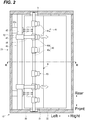
- FIG. 2 schematically a planar view of an internal structure of the fixing device 12.
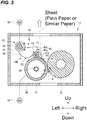
- FIG. 3 a cross-sectional view taken along the line III-III in FIG. 2 .
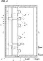
- FIG. 4 schematically illustrates a planar view of an internal structure of the fixing device 12, and illustrates a state where a claw member 41 and similar member are close to the fixing nip N.
- FIG. 5 a cross-sectional view taken along the line V-V in FIG. 4 .
- FIG. 6 schematically illustrates a planar view of an internal structure of the fixing device 12, and a state where the claw member 41 and similar member are separated from the fixing nip N.
- FIG. 7 a cross-sectional view taken along the line VII-VII in FIG. 6 .
- FIG. 8 illustrates a control system of the fixing device 12.
- the fixing device 12 includes a fixing frame 30, the fixing roller 31, the pressure roller 32, a fixing motor 33, a heater 34, and a separating unit 35.
- the fixing roller 31 as a fixing member is formed into a cylindrical shape long in the front-rear direction.
- the fixing roller 31 is rotatably supported by the fixing frame 30. While the drawing is not illustrated, the fixing roller 31 is formed by laminating release layers (fluororesin) on an outer peripheral surface of a core material made of, for example, metal (aluminum, iron, or similar metal).
- the pressure roller 32 as a pressure member is formed into a cylindrical shape long in the front-rear direction.
- the pressure roller 32 is rotatably supported by the fixing frame 30. While the drawing is not illustrated, the pressure roller 32 is formed by laminating elastic layers (for example, silicon rubber) on an outer peripheral surface of a core material made of, for example, metal (aluminum, iron, or similar metal).
- the pressure roller 32 includes release layers (fluororesin, not illustrated) coating the elastic layers.
- the pressure roller 32 is urged by an urging member (not illustrated) to be brought into pressure contact with the fixing roller 31.
- the fixing nip N is formed between the fixing roller 31 and the pressure roller 32.
- the fixing motor 33 is connected to the fixing roller 31 via a gear train (not illustrated).
- the fixing motor 33 rotatably drives the fixing roller 31 about its axis.
- the pressure roller 32 is driven by the fixing roller 31 to rotate in a direction opposite to the fixing roller 31.
- the heater 34 as heat source is, for example, a halogen heater or a ceramic heater.
- the heater 34 is located in an internal space of the fixing roller 31 (see FIG. 3 ). The heater 34 heats the fixing roller 31.
- the sheet S passes through the fixing nip N while its surface on which the toner image has been transferred is opposed to the fixing roller 31 side. This melts and applies pressure to the toner image (toners that constitute the toner image) to fix on the front or back surface of the sheet S.
- the sheet S, which has passed through the fixing nip N, is possibly attached on (wound around) the fixing roller 31 because of an influence of the melted toners (see FIG. 3 ).
- the separating unit 35 of the fixing device 12 is located so as to enable the sheet S, which is attached on the fixing roller 31 after passing through the fixing nip N, to be separated.
- the separating unit 35 is located opposed to the fixing roller 31 on a downstream side of the fixing nip N.
- the separating unit 35 includes the claw member 41 that contacts an outer peripheral surface of the fixing roller 31.
- the claw member 41 relatively slides on the outer peripheral surface of the rotating fixing roller 31 to remove the sheet S attached on (wound around) the fixing roller 31.
- a winding phenomenon of the sheet S around the fixing roller 31 easily occurs when the fixing process is performed on a tender sheet S, such as a thin paper (see FIG. 5 ). Additionally, this winding phenomenon possibly occurs when image formation is performed on the head side of the sheet S in the conveyance direction. That is because the sheet S is attached on the fixing roller 31 because of the melted toners. On the other hand, this winding phenomenon does not easily occur when the fixing process is performed on a tough sheet S, such as a cardboard (see FIG. 7 ). Thus, when the fixing process is performed on a tough sheet S, the claw member 41 is not often required. Therefore, the separating unit 35 of the fixing device 12 have a configuration that positions the claw member 41 at an appropriate position in accordance with a kind of the sheet S (for example, thickness and material), and a position of image on the sheet S.
- a kind of the sheet S for example, thickness and material
- the separating unit 35 includes a sliding member 40, the claw member 41, and a turning mechanism 42.
- the sliding member 40 and the claw member 41 are integrally formed. While the details will be described later, the turning mechanism 42 is controlled by the control device 14 to reciprocate the sliding member 40 and the claw member 41 along a rotation direction of the fixing roller 31.
- the sliding member 40 includes a slide shaft 40a and a plurality (for example, six) of sliding elements 40b. It is only necessary that one or more sliding element 40b is located in accordance with a width of the sheet S.
- the slide shaft 40a is formed into a columnar shape (bar shape) long in the front-rear direction. Both front and rear end portions of the slide shaft 40a slidably fit guide grooves G depressed on both front and rear walls of the fixing frame 30. A pair of the front and rear guide grooves G is formed into a circular arc shape along the rotation direction of the fixing roller 31 (see FIG. 3 ).
- the respective sliding elements 40b are shorter than the slide shaft 40a in the front-rear direction and are formed into a cylindrical shape having a diameter larger than that of the slide shaft 40a.
- the plurality of sliding elements 40b are each secured in the front-rear direction of the slide shaft 40a at predetermined intervals.
- the respective sliding elements 40b are located such that the sliding elements 40b have centers identical to that of the slide shaft 40a.
- Each of the sliding elements 40b (the sliding member 40) is located in a state of contacting the outer peripheral surface (surface) of the fixing roller 31.
- the claw member 41 includes a plurality (for example, six) of separation claws 41a.
- the respective separation claws 41a are located corresponding to the sliding elements 40b.
- Each of the separation claws 41a has one end portion (a base end portion) and is formed into a cantilever shape where the one end portion is secured to an upper portion of the sliding element 40b.
- the respective separation claws 41a are formed such that the separation claws 41a decrease in thickness toward the other end portions (distal end portions).
- the distal end portions of the respective separation claws 41a are formed into an acute angle viewed from front.
- Each of the separation claws 41a (the claw member 41) runs toward the fixing nip N from the sliding member 40.
- the claw member 41 is located in a state where the distal end portions of the respective separation claws 41a contact the outer peripheral surface (surface) of the fixing roller 31.
- the sliding member 40 and the claw member 41 are guided to the guide grooves G and turn about the rotation shaft of the fixing roller 31.
- the claw member 41 and the sliding member 40 are movably located along the rotation direction of the fixing roller 31.
- the sliding member 40 and the claw member 41 are movably located between a close position P1 and a separation position P2 while being guided to the respective guide grooves G.
- the close position P1 is located at the proximity of the fixing nip N (see FIG. 5 ).
- the separation position P2 is located on a downstream side of the rotation direction of the fixing roller 31 with respect to the close position P1 (see FIG. 7 ). Between the close position P1 and the separation position P2, an intermediate position P3 is located (see FIG. 3 ).
- the turning mechanism 42 includes a turning shaft 43, a pair of front and rear eccentric cams 44, a pair of front and rear tension springs 45, and a drive motor 46.
- the turning shaft 43 is formed into an approximately columnar shape (bar shape) long in the front-rear direction. Accurately, the turning shaft 43 has a cross section where a part of the turning shaft 43 is cut out. The cross section has an approximately fan shape (approximately D shape) viewed from a side planar surface (see FIG. 3 ). The turning shaft 43 is rotatably supported by both the front and rear walls of the fixing frame 30.
- the pair of the front and rear eccentric cams 44 are secured to both front and rear sides of the turning shaft 43 via boss portions 47.
- the respective boss portions 47 are formed into an approximately annular shape so as to penetrate through the turning shaft 43.
- the respective boss portions 47 are unrotatably secured to the turning shaft 43. That is, the respective boss portions 47 and the respective eccentric cams 44 integrally rotate with the turning shaft 43.
- the pair of the front and rear eccentric cams 44 have an identical shape. Thus the following mainly describes one of the eccentric cams 44.
- the eccentric cam 44 has one end portion (a base end portion) and is formed into a cantilever shape where the one end portion is secured to the boss portion 47.
- the eccentric cam 44 has a lower surface formed into an approximately fan shape (half circular shape) having a curved arc shape viewed from front.
- a cam surface 44a is formed on the lower surface of the eccentric cam 44.
- the cam surface 44a includes a close cam surface F1 and a separation cam surface F2.
- the separation cam surface F2 is formed on the boss portion 47 side (a base end side of the eccentric cam 44), and the close cam surface F1 is formed on a distal end side of the eccentric cam 44.
- the close cam surface F1 and the separation cam surface F2 are formed as curved convex surfaces having respective different distances from a rotational center (the turning shaft 43).
- the close cam surface F1 is formed so as to have a curvature larger than that of the separation cam surface F2.
- a depression portion F3 is formed between (on a connection portion of) the close cam surface F1 and the separation cam surface F2.
- the depression portion F3 is depressed on a portion at which the curvatures of the two cam surfaces F1 and F2 are switched.
- the eccentric cam 44 is rotatably (swingably) located in a state where the cam surface 44a contacts the one sliding element 40b (the sliding member 40).
- the close cam surface F1 is configured to move the claw member 41 and similar member to the close position P1.
- the separation cam surface F2 is configured to move the claw member 41 and similar member to the separation position P2.
- the claw member 41 and similar member are displaced to the separation position P2.
- the depression portion F3 is configured to move the claw member 41 and similar member to the intermediate position P3. As illustrated in FIGS. 2 and 3 , in a state where the sliding element 40b is positioned at (fitted to) the depression portion F3, the claw member 41 and similar member are displaced to the intermediate position P3.
- the pair of the front and rear tension springs 45 as an urging member are bridged between spring receiving portions 30a and the slide shaft 40a.
- the spring receiving portions 30a are formed inside a left wall of the fixing frame 30.
- the tension springs 45 are located so as to urge the sliding member 40 toward the cam surface 44a of the eccentric cam 44.
- the claw member 41 and similar member are held at the respective positions P1 to P3 by a balance between urging forces of the respective tension springs 45 and forces received from the cam surfaces 44a (F1 and F2 (including also the depression portion F3, and the same applies to the following)) of the eccentric cams 44.
- the drive motor 46 as a driving unit is connected to the turning shaft 43 via a gear train (not illustrated). While the details will be described later, the drive motor 46 is drivingly controlled by the control device 14. This causes the turning shaft 43 to rotate in positive and negative directions. That is, the drive motor 46 swings (reciprocally rotates) the respective eccentric cams 44 about the turning shaft 43.
- the multi-functional peripheral 1 includes an operation panel 50 (see FIG. 8 ) with which a user performs input operation.
- the user operates the operation panel 50 or an external terminal (not illustrated) connected to the multi-functional peripheral 1 to input a size and a kind (for example, thickness and material) of the sheet S.
- the multi-functional peripheral 1 includes, for example, a power source (not illustrated) that supplies the respective units with power.
- control device 14 includes an arithmetic processing unit (not illustrated) that executes arithmetic processing based on, for example, a program stored in a storage unit (not illustrated).
- arithmetic processing unit (not illustrated) that executes arithmetic processing based on, for example, a program stored in a storage unit (not illustrated).
- the fixing motor 33, the heater 34, the drive motor 46, and the operation panel 50 and similar unit (the respective units and similar unit) are electrically connected to the control device 14.
- the respective units and similar unit are appropriately controlled by the control device 14. While the drawing is not illustrated, other units and similar unit, which are required for the image formation process, are also connected to and controlled by the control device 14.
- the information which indicates a size and a kind of the sheet S and has been input by the user from the operation panel 50 or the external terminal, is transmitted to the control device 14.
- the control device 14 recognizes an image formation position (printing position) on the sheet S based on the image data used for the image formation process.
- the control device 14 controls the turning mechanism 42 in accordance with the kind of the sheet S or the position of toner image to be transferred on the sheet S.
- the fixing process on a sheet S is performed in the state (the initial state) where the claw member 41 and similar member are moved to the intermediate position P3 (see FIGS. 2 and 3 ). Subsequently, for example, when the fixing process is performed on a tender and thin sheet S, or when image formation (the fixing process of a toner image) is performed on the head side of the sheet S in the conveyance direction, the claw member 41 and similar member are moved to the close position P1 (see FIGS. 4 and 5 ).
- the drive motor 46 of the turning mechanism 42 is drivingly controlled by the control device 14 to cause the turning shaft 43 (the respective eccentric cams 44) to rotate clockwise in FIG. 3 .
- the sliding member 40 is pushed rightward by the respective turning eccentric cams 44 (see FIG. 4 ) against the urging force of the respective tension springs 45.
- the sliding members 40 relatively slide to the close cam surface F1 from the depression portion F3. That is, the claw members 41 and similar member are moved to the close position P1 from the intermediate position P3 (see FIGS. 4 and 5 ).
- the control device 14 stops the driving of the drive motor 46.
- the control device 14 performs an image formation process on a thin sheet S in a state where the claw member 41 and similar member are displaced to the close position P1. This removes the sheet S from the fixing roller 31.
- the close cam surface F1 contacting the claw member 41 and similar member has a small curvature radius, and thus the respective separation claws 41a contact the fixing roller 31 under a large pressure (compared with a case where the separation cam surface F2 contacts the claw member 41 and similar member).
- the claw members 41 and similar member are moved to the separation position P2 (see FIGS. 6 and 7 ).
- the drive motor 46 is drivingly controlled by the control device 14 to cause the respective eccentric cams 44 to rotate anticlockwise in FIG. 3 .
- the sliding members 40 are pressed to the respective turning eccentric cams 44 (in a left direction) by the urging forces of the respective tension springs 45.
- the sliding members 40 relatively slide to the separation cam surface F2 from the depression portion F3. That is, the claw members 41 and similar member are moved to the separation position P2 from the intermediate position P3 (see FIGS. 6 and 7 ).
- the control device 14 stops the driving of the drive motor 46.
- the control device 14 performs an image formation process on a thick sheet S in a state where the claw member 41 and similar member are displaced to the separation position P2. This prevents a collision of the sheet S with the claw member 41 (the respective separation claws 41a).
- the sliding member 40 receives both pressing forces from the respective swinging eccentric cams 44 and tensile forces from the respective tension springs 45.
- the claw members 41 and similar member are movably located between the close position P1 and the separation position P2 in accordance with a ratio of the pressing force to the tensile force, which are received by the sliding member 40. Then, the control device 14 controls the movement of the claw members 41 and similar member in accordance with a kind of the sheet S and a position of an image on the sheet S.
- the turning mechanism 42 moves the claw members 41 to the proximity of the fixing nip N (the close position P1). This claw members 41 remove the sheet S, which has passed through the fixing nip N, from the fixing roller 31. This prevents winding of the sheet S around the fixing roller 31.
- the turning mechanism 42 moves the claw members 41 to the separation position P2, which is apart from the fixing nip N.
- the claw member 41 is located at an appropriate position in accordance with, for example, a kind of the sheet S.
- the close position P1 is configured to be positioned at a position at which the sheet S is separable from the fixing roller 31.
- the separation position P2 is configured to be positioned at a position at which the collision of the sheet S is preventable.
- the intermediate position P3 is configured to be positioned at a position at which the fixing process is appropriately performed on, what is called, a plain paper. That is, the intermediate position P3 is configured as a home position. It is preferred that the close position P1, the separation position P2, and the intermediate position P3 be positioned on the basis of, for example, outer diameters of the respective rollers 31 and 32, temperature, pressure of the fixing nip N, and properties of the toners.
- Each of the sliding elements 40b (the sliding member 40) and each of the separation claws 41a (the claw member 41) contact the surface of the fixing roller 31, which enables each of the separation claws 41a (the claw member 41) to move while holding a constant contact angle on the surface of the fixing roller 31. Since constant contact pressure of each of the separation claws 41a (the claw member 41) is held, this ensures the reduced abrasion of the fixing roller 31.
- the sliding member 40 is pressed to the cam surfaces 44a (F1 to F3) of the respective eccentric cams 44 by the urging force of the tension springs 45.
- the sliding member 40 relatively slides on the cam surfaces 44a of the respective rotating eccentric cams 44 to cause the claw members 41 and similar member to reciprocate along the rotation direction of the fixing roller 31.
- employing a cam mechanism as the turning mechanism 42 ensures the stable movement of the claw member 41 and similar member.
- the respective eccentric cams 44 of the fixing device 12 is configured to swing (reciprocate)
- the invention is not limited to this.
- a circular plate cam that is rotatable by 360 degrees may be employed instead of the respective eccentric cams 44.
- control device 14 of the fixing device 12 integrally controls the multi-functional peripheral 1
- the invention is not limited to this.
- a control unit to control the fixing device 12 may be independently provided in addition to the control device 14.
- the above has described the case where the invention is apply to the multi-functional peripheral 1 (monochrome), not limited to this, the invention may be applied to, for example, a color printer and a facsimile.
Landscapes
- Physics & Mathematics (AREA)
- General Physics & Mathematics (AREA)
- Fixing For Electrophotography (AREA)
Abstract
Description
- This invention relates to a fixing device and an image forming apparatus including the fixing device.
- Unless otherwise indicated herein, the description in this section is not prior art to the claims in this application and is not admitted to be prior art by inclusion in this section.
- A typical image forming apparatus using an electrophotographic method includes a fixing device including a pressure roller that is brought into pressure contact with a fixing roller. The fixing device applies pressure and heats to sheets passing between both rollers (through a fixing nip) to fix toner images on the sheets (fixing process). The sheet enters the fixing nip while the surface on which the toner image is transferred is opposed to the fixing roller side.
- The sheet, which have passed through the fixing nip, is possibly wound around the fixing roller because of viscosity of melted toners. In view of this, the fixing device includes a separation claw constantly contacting a surface of the fixing roller. This separation claw prevents the sheet after a fixing process from being wound around the fixing roller. However, the separation claw constantly contacts (slidably contact) the fixing roller, and this causes a problem that the fixing roller is easily abraded.
- There is proposed a technique to solve the above-described problem. For example, there is proposed a fixing device including a mechanism (solenoid) that causes a separation claw to contact and be separated from a fixing roller. This mechanism is controlled such that the separation claw contacts the fixing roller only when the fixing process is performed.
- A fixing device according to one aspect of the invention includes a fixing member, a pressure member, and a separating unit. The fixing member is rotatably located. The fixing member is heated or heatable by a heat source. The pressure member is rotatably located. The pressure member is in a pressure contact or bringable in a pressure contact with the fixing member to form a fixing nip. The separating unit is configured to separate a sheet from the fixing member. The sheet is attached on the fixing member when passing through the fixing nip. The separating unit includes a sliding member, a claw member, and a turning mechanism. The sliding member is located in a state of contacting a surface of the fixing member. The claw member runs toward the fixing nip from the sliding member. The claw member has a distal end portion. The claw member is located in a state where the distal end portion contacts the surface of the fixing member. The turning mechanism reciprocates the sliding member and the claw member along a rotation direction of the fixing member.
- These as well as other aspects, advantages, and alternatives will become apparent to those of ordinary skill in the art by reading the following detailed description with reference where appropriate to the accompanying drawings. Further, it should be understood that the description provided in this summary section and elsewhere in this document is intended to illustrate the claimed subject matter by way of example and not by way of limitation.
-
- FIG. 1
- schematically illustrates a cross section of an internal structure of a multi-functional peripheral according to one exemplary embodiment of the invention;
- FIG. 2
- schematically illustrates a planar view of an internal structure of a fixing device according to the one exemplary embodiment;
- FIG. 3
- illustrates a cross-sectional view taken along the line III-III in
FIG. 2 ; - FIG. 4
- schematically illustrates a planar view of an internal structure of the fixing device according to the one exemplary embodiment, and illustrates a state where a claw member and similar member are close to a fixing nip;
- FIG. 5
- illustrates a cross-sectional view taken along the line V-V in
FIG. 4 ; - FIG. 6
- schematically illustrates a planar view of an internal structure of the fixing device according to the one exemplary embodiment, and illustrates a state where the claw member and similar member are separated from the fixing nip;
- FIG. 7
- illustrates a cross-sectional view taken along the line VII-VII in
FIG. 6 ; and - FIG. 8
- illustrates a block diagram of a control system of the fixing device according to the one exemplary embodiment.
- Example apparatuses are described herein. Other example embodiments or features may further be utilized, and other changes may be made, without departing from the spirit or scope of the subject matter presented herein. In the following detailed description, reference is made to the accompanying drawings, which form a part thereof.
- The example embodiments described herein are not meant to be limiting. It will be readily understood that the aspects of the present invention, as generally described herein, and illustrated in the drawings, can be arranged, substituted, combined, separated, and designed in a wide variety of different configurations, all of which are explicitly contemplated herein.
- The following describes a preferred embodiment of the invention with reference to the accompanying drawings. Hereinafter, paper-surface-front sides in
FIGS. 1 ,3 ,5 , and7 are defined as a front surface, and the preferred embodiment of the invention is described using directions indicated in the respective drawings as a reference. In the following description, a term of "conveyance direction" means a conveyance direction of a sheet S. Further, "upstream," "downstream," and terms similar to these mean an "upstream" and a "downstream" of the conveyance direction, and a concept similar to these. - The following describes a multi-functional peripheral 1 as an image forming apparatus with reference to
FIG. 1. FIG. 1 schematically illustrates a cross section of an internal structure of the multi-functional peripheral 1. - The multi-functional peripheral 1 includes a
printing device 1A and ascanning device 1B. Theprinting device 1A forms images on the sheet S using an electrophotographic method. Thescanning device 1B includes components (not illustrated) that optically read image information of an original document. Thescanning device 1B is located above theprinting device 1A across an in-barrel space 1C. Thescanning device 1B has a known structure, and thus the following omits the detailed description. - The
printing device 1A includes an apparatusmain body 2, a sheet feed cassette 3, and asheet discharge tray 4. The sheet feed cassette 3 is located in a lower portion of the apparatusmain body 2 and is removably attachable in a front-rear direction. The sheet feed cassette 3 houses paper (a bundle of) sheets S. Thesheet discharge tray 4 is located on a top surface of the apparatus main body 2 (a bottom surface of the in-barrel space 1C). - Inside the apparatus
main body 2, amain conveyance path 5 and an invertingconveyance path 6 are formed. Themain conveyance path 5 vertically runs from the sheet feed cassette 3 to thesheet discharge tray 4. The invertingconveyance path 6 vertically runs so as to communicate between an upstream portion and a downstream portion of themain conveyance path 5. - The
printing device 1A includes apaper sheet feeder 10, animage forming unit 11, a fixingdevice 12, a dischargingroller pair 13, and acontrol device 14. Thepaper sheet feeder 10 is located in an upstream end portion of themain conveyance path 5. Thepaper sheet feeder 10 conveys the sheets S from the sheet feed cassette 3 one by one to themain conveyance path 5. Theimage forming unit 11 and the fixingdevice 12 are located in an intermediate portion of themain conveyance path 5. The dischargingroller pair 13 is located on a downstream end portion of themain conveyance path 5. The control device 14 (control unit) integrally controls operations of the multi-functional peripheral 1. - The
image forming unit 11 transfers a toner image on the sheet S. Theimage forming unit 11 includes atoner container 20, adrum unit 21, and alight scanning device 22. Thetoner container 20 houses, for example, a black toner (developer). Thedrum unit 21 includes aphotoreceptor drum 23, a chargingapparatus 24, a developingdevice 25, atransfer roller 26, and acleaning apparatus 27. The chargingapparatus 24, the developingdevice 25, thetransfer roller 26, and thecleaning apparatus 27 are located in a peripheral area of thephotoreceptor drum 23 in order of the transfer process. Thetransfer roller 26 is brought into pressure contact with thephotoreceptor drum 23 from a lower side to form a transfer nip 26a. - While the details will be described later, the fixing
device 12 includes apressure roller 32 that is brought into pressure contact with a fixingroller 31 to form a fixing nip N.The fixing device 12 heats the sheet S passing through the fixing nip N to fix the toner image on the sheet S while applying pressure. - Here, the following describes operations of the
printing device 1A. Thecontrol device 14 performs an image formation process based on, for example, image data read by thescanning device 1B as follows. - The charging
apparatus 24 charges a surface of thephotoreceptor drum 23. Thelight scanning device 22 performs exposure (see the dashed line arrow inFIG. 1 ) in accordance with the image data on thephotoreceptor drum 23. The developingdevice 25 develops an electrostatic latent image on thephotoreceptor drum 23 into the toner image. On the other hand, the sheet S is transmitted to themain conveyance path 5 from thepaper sheet feeder 10. The toner image is transferred on a surface of the sheet S passing through the transfer nip 26a. The fixingdevice 12 fixes the toner image on the surface of the sheet S. After a fixing process, the sheet S is discharged on thesheet discharge tray 4 by the dischargingroller pair 13. - When image formations (duplex printing) are performed on both the front and back surfaces of the sheet S, the sheet S is reversely conveyed by the discharging
roller pair 13 to be conveyed to the invertingconveyance path 6 after the fixing process. After that, similarly to the above, the transfer and the fixing process of toner images are performed on the back surface of the sheet S. Then, the sheet S, on which the duplex printing has been performed, is discharged on thesheet discharge tray 4. - Next, the following describes the fixing
device 12 with reference toFIGS. 2 to 6 .FIG. 2 schematically a planar view of an internal structure of the fixingdevice 12.FIG. 3 a cross-sectional view taken along the line III-III inFIG. 2 .FIG. 4 schematically illustrates a planar view of an internal structure of the fixingdevice 12, and illustrates a state where aclaw member 41 and similar member are close to the fixing nip N.FIG. 5 a cross-sectional view taken along the line V-V inFIG. 4 .FIG. 6 schematically illustrates a planar view of an internal structure of the fixingdevice 12, and a state where theclaw member 41 and similar member are separated from the fixing nip N.FIG. 7 a cross-sectional view taken along the line VII-VII inFIG. 6 .FIG. 8 illustrates a control system of the fixingdevice 12. - As illustrated in
FIGS. 2 and3 , the fixingdevice 12 includes a fixingframe 30, the fixingroller 31, thepressure roller 32, a fixingmotor 33, aheater 34, and a separatingunit 35. - The fixing
roller 31 as a fixing member is formed into a cylindrical shape long in the front-rear direction. The fixingroller 31 is rotatably supported by the fixingframe 30. While the drawing is not illustrated, the fixingroller 31 is formed by laminating release layers (fluororesin) on an outer peripheral surface of a core material made of, for example, metal (aluminum, iron, or similar metal). - The
pressure roller 32 as a pressure member is formed into a cylindrical shape long in the front-rear direction. Thepressure roller 32 is rotatably supported by the fixingframe 30. While the drawing is not illustrated, thepressure roller 32 is formed by laminating elastic layers (for example, silicon rubber) on an outer peripheral surface of a core material made of, for example, metal (aluminum, iron, or similar metal). Thepressure roller 32 includes release layers (fluororesin, not illustrated) coating the elastic layers. Thepressure roller 32 is urged by an urging member (not illustrated) to be brought into pressure contact with the fixingroller 31. The fixing nip N is formed between the fixingroller 31 and thepressure roller 32. - The fixing
motor 33 is connected to the fixingroller 31 via a gear train (not illustrated). The fixingmotor 33 rotatably drives the fixingroller 31 about its axis. Thepressure roller 32 is driven by the fixingroller 31 to rotate in a direction opposite to the fixingroller 31. - The
heater 34 as heat source is, for example, a halogen heater or a ceramic heater. Theheater 34 is located in an internal space of the fixing roller 31 (seeFIG. 3 ). Theheater 34 heats the fixingroller 31. - The sheet S passes through the fixing nip N while its surface on which the toner image has been transferred is opposed to the fixing
roller 31 side. This melts and applies pressure to the toner image (toners that constitute the toner image) to fix on the front or back surface of the sheet S. The sheet S, which has passed through the fixing nip N, is possibly attached on (wound around) the fixingroller 31 because of an influence of the melted toners (seeFIG. 3 ). Thus, the separatingunit 35 of the fixingdevice 12 is located so as to enable the sheet S, which is attached on the fixingroller 31 after passing through the fixing nip N, to be separated. - As illustrated in
FIG. 3 , the separatingunit 35 is located opposed to the fixingroller 31 on a downstream side of the fixing nip N. The separatingunit 35 includes theclaw member 41 that contacts an outer peripheral surface of the fixingroller 31. Theclaw member 41 relatively slides on the outer peripheral surface of the rotating fixingroller 31 to remove the sheet S attached on (wound around) the fixingroller 31. - Here, a winding phenomenon of the sheet S around the fixing
roller 31 easily occurs when the fixing process is performed on a tender sheet S, such as a thin paper (seeFIG. 5 ). Additionally, this winding phenomenon possibly occurs when image formation is performed on the head side of the sheet S in the conveyance direction. That is because the sheet S is attached on the fixingroller 31 because of the melted toners. On the other hand, this winding phenomenon does not easily occur when the fixing process is performed on a tough sheet S, such as a cardboard (seeFIG. 7 ). Thus, when the fixing process is performed on a tough sheet S, theclaw member 41 is not often required. Therefore, the separatingunit 35 of the fixingdevice 12 have a configuration that positions theclaw member 41 at an appropriate position in accordance with a kind of the sheet S (for example, thickness and material), and a position of image on the sheet S. - As illustrated in
FIGS. 2 and3 , the separatingunit 35 includes a slidingmember 40, theclaw member 41, and aturning mechanism 42. The slidingmember 40 and theclaw member 41 are integrally formed. While the details will be described later, theturning mechanism 42 is controlled by thecontrol device 14 to reciprocate the slidingmember 40 and theclaw member 41 along a rotation direction of the fixingroller 31. - The sliding
member 40 includes aslide shaft 40a and a plurality (for example, six) of slidingelements 40b. It is only necessary that one or more slidingelement 40b is located in accordance with a width of the sheet S. - The
slide shaft 40a is formed into a columnar shape (bar shape) long in the front-rear direction. Both front and rear end portions of theslide shaft 40a slidably fit guide grooves G depressed on both front and rear walls of the fixingframe 30. A pair of the front and rear guide grooves G is formed into a circular arc shape along the rotation direction of the fixing roller 31 (seeFIG. 3 ). - The respective sliding
elements 40b are shorter than theslide shaft 40a in the front-rear direction and are formed into a cylindrical shape having a diameter larger than that of theslide shaft 40a. The plurality of slidingelements 40b are each secured in the front-rear direction of theslide shaft 40a at predetermined intervals. The respective slidingelements 40b are located such that the slidingelements 40b have centers identical to that of theslide shaft 40a. Each of the slidingelements 40b (the sliding member 40) is located in a state of contacting the outer peripheral surface (surface) of the fixingroller 31. - The
claw member 41 includes a plurality (for example, six) ofseparation claws 41a. Therespective separation claws 41a are located corresponding to the slidingelements 40b. Each of theseparation claws 41a has one end portion (a base end portion) and is formed into a cantilever shape where the one end portion is secured to an upper portion of the slidingelement 40b. Therespective separation claws 41a are formed such that theseparation claws 41a decrease in thickness toward the other end portions (distal end portions). The distal end portions of therespective separation claws 41a are formed into an acute angle viewed from front. Each of theseparation claws 41a (the claw member 41) runs toward the fixing nip N from the slidingmember 40. Theclaw member 41 is located in a state where the distal end portions of therespective separation claws 41a contact the outer peripheral surface (surface) of the fixingroller 31. The slidingmember 40 and theclaw member 41 are guided to the guide grooves G and turn about the rotation shaft of the fixingroller 31. Theclaw member 41 and the slidingmember 40 are movably located along the rotation direction of the fixingroller 31. - The sliding
member 40 and the claw member 41 (hereinafter referred to as "claw member 41 and similar member") are movably located between a close position P1 and a separation position P2 while being guided to the respective guide grooves G. The close position P1 is located at the proximity of the fixing nip N (seeFIG. 5 ). The separation position P2 is located on a downstream side of the rotation direction of the fixingroller 31 with respect to the close position P1 (seeFIG. 7 ). Between the close position P1 and the separation position P2, an intermediate position P3 is located (seeFIG. 3 ). - As illustrated in
FIGS. 2 and3 , theturning mechanism 42 includes a turningshaft 43, a pair of front and reareccentric cams 44, a pair of front and rear tension springs 45, and adrive motor 46. - The turning
shaft 43 is formed into an approximately columnar shape (bar shape) long in the front-rear direction. Accurately, the turningshaft 43 has a cross section where a part of the turningshaft 43 is cut out. The cross section has an approximately fan shape (approximately D shape) viewed from a side planar surface (seeFIG. 3 ). The turningshaft 43 is rotatably supported by both the front and rear walls of the fixingframe 30. - The pair of the front and rear
eccentric cams 44 are secured to both front and rear sides of the turningshaft 43 viaboss portions 47. Therespective boss portions 47 are formed into an approximately annular shape so as to penetrate through the turningshaft 43. Therespective boss portions 47 are unrotatably secured to the turningshaft 43. That is, therespective boss portions 47 and the respectiveeccentric cams 44 integrally rotate with the turningshaft 43. The pair of the front and reareccentric cams 44 have an identical shape. Thus the following mainly describes one of theeccentric cams 44. - As illustrated in
FIG. 3 , theeccentric cam 44 has one end portion (a base end portion) and is formed into a cantilever shape where the one end portion is secured to theboss portion 47. Theeccentric cam 44 has a lower surface formed into an approximately fan shape (half circular shape) having a curved arc shape viewed from front. On the lower surface of theeccentric cam 44, acam surface 44a is formed. Thecam surface 44a includes a close cam surface F1 and a separation cam surface F2. - The separation cam surface F2 is formed on the
boss portion 47 side (a base end side of the eccentric cam 44), and the close cam surface F1 is formed on a distal end side of theeccentric cam 44. The close cam surface F1 and the separation cam surface F2 are formed as curved convex surfaces having respective different distances from a rotational center (the turning shaft 43). The close cam surface F1 is formed so as to have a curvature larger than that of the separation cam surface F2. Between (on a connection portion of) the close cam surface F1 and the separation cam surface F2, a depression portion F3 is formed. The depression portion F3 is depressed on a portion at which the curvatures of the two cam surfaces F1 and F2 are switched. - The
eccentric cam 44 is rotatably (swingably) located in a state where thecam surface 44a contacts the one slidingelement 40b (the sliding member 40). The close cam surface F1 is configured to move theclaw member 41 and similar member to the close position P1. As illustrated inFIGS. 4 and5 , in a state where the slidingelement 40b contacts the close cam surface F1, theclaw member 41 and similar member are displaced to the close position P1. Subsequently, the separation cam surface F2 is configured to move theclaw member 41 and similar member to the separation position P2. As illustrated inFIGS. 6 and7 , in a state where the slidingelement 40b contacts the separation cam surface F2, theclaw member 41 and similar member are displaced to the separation position P2. Further, the depression portion F3 is configured to move theclaw member 41 and similar member to the intermediate position P3. As illustrated inFIGS. 2 and3 , in a state where the slidingelement 40b is positioned at (fitted to) the depression portion F3, theclaw member 41 and similar member are displaced to the intermediate position P3. - As illustrated in
FIG. 2 , the pair of the front and rear tension springs 45 as an urging member are bridged betweenspring receiving portions 30a and theslide shaft 40a. Thespring receiving portions 30a are formed inside a left wall of the fixingframe 30. The tension springs 45 are located so as to urge the slidingmember 40 toward thecam surface 44a of theeccentric cam 44. Theclaw member 41 and similar member are held at the respective positions P1 to P3 by a balance between urging forces of the respective tension springs 45 and forces received from the cam surfaces 44a (F1 and F2 (including also the depression portion F3, and the same applies to the following)) of theeccentric cams 44. - As illustrated in
FIG. 3 , thedrive motor 46 as a driving unit is connected to the turningshaft 43 via a gear train (not illustrated). While the details will be described later, thedrive motor 46 is drivingly controlled by thecontrol device 14. This causes the turningshaft 43 to rotate in positive and negative directions. That is, thedrive motor 46 swings (reciprocally rotates) the respectiveeccentric cams 44 about the turningshaft 43. - The multi-functional peripheral 1 includes an operation panel 50 (see
FIG. 8 ) with which a user performs input operation. The user operates theoperation panel 50 or an external terminal (not illustrated) connected to the multi-functional peripheral 1 to input a size and a kind (for example, thickness and material) of the sheet S. The multi-functional peripheral 1 includes, for example, a power source (not illustrated) that supplies the respective units with power. - Here, the above-described
control device 14 includes an arithmetic processing unit (not illustrated) that executes arithmetic processing based on, for example, a program stored in a storage unit (not illustrated). As illustrated inFIG. 8 , the fixingmotor 33, theheater 34, thedrive motor 46, and theoperation panel 50 and similar unit (the respective units and similar unit) are electrically connected to thecontrol device 14. The respective units and similar unit are appropriately controlled by thecontrol device 14. While the drawing is not illustrated, other units and similar unit, which are required for the image formation process, are also connected to and controlled by thecontrol device 14. - Next, with reference to
FIGS. 2 to 7 , the following describes an action of the separating unit 35 (displacement control of theclaw member 41 and similar member). Assume that a state where theclaw member 41 and similar member are displaced to the intermediate position P3 is an initial state (seeFIGS. 2 and3 ). - The information, which indicates a size and a kind of the sheet S and has been input by the user from the
operation panel 50 or the external terminal, is transmitted to thecontrol device 14. Thecontrol device 14 recognizes an image formation position (printing position) on the sheet S based on the image data used for the image formation process. Thecontrol device 14 controls theturning mechanism 42 in accordance with the kind of the sheet S or the position of toner image to be transferred on the sheet S. - For example, the fixing process on a sheet S, such as, what is called, a plain paper, is performed in the state (the initial state) where the
claw member 41 and similar member are moved to the intermediate position P3 (seeFIGS. 2 and3 ). Subsequently, for example, when the fixing process is performed on a tender and thin sheet S, or when image formation (the fixing process of a toner image) is performed on the head side of the sheet S in the conveyance direction, theclaw member 41 and similar member are moved to the close position P1 (seeFIGS. 4 and5 ). In detail, thedrive motor 46 of theturning mechanism 42 is drivingly controlled by thecontrol device 14 to cause the turning shaft 43 (the respective eccentric cams 44) to rotate clockwise inFIG. 3 . Then, the slidingmember 40 is pushed rightward by the respective turning eccentric cams 44 (seeFIG. 4 ) against the urging force of the respective tension springs 45. The sliding members 40 (respective slidingelements 40b) relatively slide to the close cam surface F1 from the depression portion F3. That is, theclaw members 41 and similar member are moved to the close position P1 from the intermediate position P3 (seeFIGS. 4 and5 ). When theclaw members 41 and similar member are moved up to the close position P1, thecontrol device 14 stops the driving of thedrive motor 46. - The
control device 14 performs an image formation process on a thin sheet S in a state where theclaw member 41 and similar member are displaced to the close position P1. This removes the sheet S from the fixingroller 31. The close cam surface F1 contacting theclaw member 41 and similar member has a small curvature radius, and thus therespective separation claws 41a contact the fixingroller 31 under a large pressure (compared with a case where the separation cam surface F2 contacts theclaw member 41 and similar member). - On the other hand, when the fixing process is performed on a tough and thick sheet S, the
claw members 41 and similar member are moved to the separation position P2 (seeFIGS. 6 and7 ). In detail, in the case of the initial state, thedrive motor 46 is drivingly controlled by thecontrol device 14 to cause the respectiveeccentric cams 44 to rotate anticlockwise inFIG. 3 . Then, the sliding members 40 (respective slidingelements 40b) are pressed to the respective turning eccentric cams 44 (in a left direction) by the urging forces of the respective tension springs 45. The sliding members 40 (respective slidingelements 40b) relatively slide to the separation cam surface F2 from the depression portion F3. That is, theclaw members 41 and similar member are moved to the separation position P2 from the intermediate position P3 (seeFIGS. 6 and7 ). After theclaw member 41 and similar member are moved up to the separation position P2, thecontrol device 14 stops the driving of thedrive motor 46. - The
control device 14 performs an image formation process on a thick sheet S in a state where theclaw member 41 and similar member are displaced to the separation position P2. This prevents a collision of the sheet S with the claw member 41 (therespective separation claws 41a). - As described above, the sliding
member 40 receives both pressing forces from the respective swingingeccentric cams 44 and tensile forces from the respective tension springs 45. Theclaw members 41 and similar member are movably located between the close position P1 and the separation position P2 in accordance with a ratio of the pressing force to the tensile force, which are received by the slidingmember 40. Then, thecontrol device 14 controls the movement of theclaw members 41 and similar member in accordance with a kind of the sheet S and a position of an image on the sheet S. - According to the above-described
fixing device 12, for example, when the fixing process is performed on a thin sheet S, or when image formation is performed on the head side of the sheet S in the conveyance direction, theturning mechanism 42 moves theclaw members 41 to the proximity of the fixing nip N (the close position P1). Thisclaw members 41 remove the sheet S, which has passed through the fixing nip N, from the fixingroller 31. This prevents winding of the sheet S around the fixingroller 31. On the other hand, when the fixing process is performed on a thick sheet S, theturning mechanism 42 moves theclaw members 41 to the separation position P2, which is apart from the fixing nip N. Then, this prevents the sheet S, which has passed through the fixing nip N, from colliding with theclaw members 41 to ensure the reduced load provided to the fixingroller 31 by theclaw member 41. This ensures the reduced damage and abrasion of the fixingroller 31. As described above, theclaw member 41 is located at an appropriate position in accordance with, for example, a kind of the sheet S. - The close position P1 is configured to be positioned at a position at which the sheet S is separable from the fixing
roller 31. The separation position P2 is configured to be positioned at a position at which the collision of the sheet S is preventable. The intermediate position P3 is configured to be positioned at a position at which the fixing process is appropriately performed on, what is called, a plain paper. That is, the intermediate position P3 is configured as a home position. It is preferred that the close position P1, the separation position P2, and the intermediate position P3 be positioned on the basis of, for example, outer diameters of therespective rollers - Each of the sliding
elements 40b (the sliding member 40) and each of theseparation claws 41a (the claw member 41) contact the surface of the fixingroller 31, which enables each of theseparation claws 41a (the claw member 41) to move while holding a constant contact angle on the surface of the fixingroller 31. Since constant contact pressure of each of theseparation claws 41a (the claw member 41) is held, this ensures the reduced abrasion of the fixingroller 31. - According to the above-described
fixing device 12, the slidingmember 40 is pressed to the cam surfaces 44a (F1 to F3) of the respectiveeccentric cams 44 by the urging force of the tension springs 45. The slidingmember 40 relatively slides on the cam surfaces 44a of the respective rotatingeccentric cams 44 to cause theclaw members 41 and similar member to reciprocate along the rotation direction of the fixingroller 31. Thus, employing a cam mechanism as theturning mechanism 42 ensures the stable movement of theclaw member 41 and similar member. - While the respective
eccentric cams 44 of the fixingdevice 12 according to the embodiment is configured to swing (reciprocate), the invention is not limited to this. For example, a circular plate cam that is rotatable by 360 degrees may be employed instead of the respectiveeccentric cams 44. - While the
control device 14 of the fixingdevice 12 according to the above-described embodiment integrally controls the multi-functional peripheral 1, the invention is not limited to this. For example, a control unit to control the fixingdevice 12 may be independently provided in addition to thecontrol device 14. - While in the respective embodiments, as one example, the above has described the case where the invention is apply to the multi-functional peripheral 1 (monochrome), not limited to this, the invention may be applied to, for example, a color printer and a facsimile.
- While various aspects and embodiments have been disclosed herein, other aspects and embodiments will be apparent to those skilled in the art. The various aspects and embodiments disclosed herein are for purposes of illustration and are not intended to be limiting, with the true scope and spirit being indicated by the following claims.
Claims (5)
- A fixing device (12) comprising:- a rotatably located fixing member (31), the fixing member (31) being heatable by a heat source;- a rotatably located pressure member (32), the pressure member (32) being bringable in a pressure contact with the fixing member (31) to form a fixing nip (N); and- a separating unit (35) configured to separate a sheet (S) from the fixing member (31), the sheet (S) being attached on the fixing member (31) when passing through the fixing nip (N),wherein the separating unit (35) includes:- a sliding member (40) located in a state of contacting a surface of the fixing member (31);- a claw member (41) running toward the fixing nip (N) from the sliding member (40), the claw member (41) having a distal end portion, the claw member (41) being located in a state where the distal end portion contacts the surface of the fixing member (31); and- a turning mechanism (42) that is configured to reciprocate the sliding member (40) and the claw member (41) along a rotation direction of the fixing member (31).
- The fixing device (12) according to claim 1, further comprising:- a control unit (14) for controlling the turning mechanism (42) in accordance with a kind of the sheet (S) or a position of a toner image to be transferred on the sheet (S),wherein the sliding member (40) and the claw member (41) are movably located between a close position (P1) and a separation position (P2), the close position (P1) being located at a proximity of the fixing nip (N), the separation position (P2) being located on a downstream side in the rotation direction of the fixing member (31) with respect to the close position (P1).
- The fixing device (12) according to claim 2,
wherein the turning mechanism (42) includes:- an eccentric cam (44) rotatably located in a state of contacting the sliding member (40);- an urging member that is configured to urge the sliding member (40) to a cam surface (44a) of the eccentric cam (44); and- a driving unit drivingly controlled by the control unit (14) to cause the eccentric cam (44) to rotate. - The fixing device (12) according to claim 3,
wherein the cam surface (44a) of the eccentric cam (44) includes:- a close cam surface (44a) that is configured to move the sliding member (40) and the claw member (41) to the close position (P1); and- a separation cam surface (44a) that is configured to move the sliding member (40) and the claw member (41) to the separation position (P2),wherein a depression portion (F3) is formed between the close cam surface (44a) and the separation cam surface (44a), the depression portion (F3) moving the sliding member (40) and the claw member (41) to an intermediate position (P3) located between the close position (P1) and the separation position (P2). - An image forming apparatus comprising:- an image forming unit that transfers a toner image on a sheet (S); and- the fixing device (12) according to one of claims 1 to 4, the fixing device (12) fixing the toner image on the sheet (S).
Applications Claiming Priority (1)
| Application Number | Priority Date | Filing Date | Title |
|---|---|---|---|
| JP2016040963A JP6406286B2 (en) | 2016-03-03 | 2016-03-03 | Fixing apparatus and image forming apparatus having the same |
Publications (2)
| Publication Number | Publication Date |
|---|---|
| EP3214502A1 true EP3214502A1 (en) | 2017-09-06 |
| EP3214502B1 EP3214502B1 (en) | 2019-01-02 |
Family
ID=58212933
Family Applications (1)
| Application Number | Title | Priority Date | Filing Date |
|---|---|---|---|
| EP17158387.5A Not-in-force EP3214502B1 (en) | 2016-03-03 | 2017-02-28 | Fixing device capable of setting position of claw member in accordance with kind of sheet, and image forming apparatus including the same |
Country Status (3)
| Country | Link |
|---|---|
| EP (1) | EP3214502B1 (en) |
| JP (1) | JP6406286B2 (en) |
| CN (1) | CN107153347B (en) |
Cited By (2)
| Publication number | Priority date | Publication date | Assignee | Title |
|---|---|---|---|---|
| CN109581841A (en) * | 2017-09-28 | 2019-04-05 | 兄弟工业株式会社 | Image forming apparatus |
| US20250021036A1 (en) * | 2023-07-11 | 2025-01-16 | Canon Kabushiki Kaisha | Fixing device and image forming apparatus |
Families Citing this family (1)
| Publication number | Priority date | Publication date | Assignee | Title |
|---|---|---|---|---|
| JP7102916B2 (en) * | 2018-05-08 | 2022-07-20 | 京セラドキュメントソリューションズ株式会社 | Fixing device and image forming device |
Citations (3)
| Publication number | Priority date | Publication date | Assignee | Title |
|---|---|---|---|---|
| US20100086332A1 (en) * | 2008-10-08 | 2010-04-08 | Brother Kogyo Kabushiki Kaisha | Image Forming Device With Downsizing Arrangement of Fixing Device |
| JP2012203158A (en) * | 2011-03-25 | 2012-10-22 | Kyocera Document Solutions Inc | Fixing device and image forming apparatus including the same |
| US20150309455A1 (en) * | 2014-04-25 | 2015-10-29 | Oki Data Corporation | Fixing device and image forming apparatus |
Family Cites Families (9)
| Publication number | Priority date | Publication date | Assignee | Title |
|---|---|---|---|---|
| JPS6331059Y2 (en) * | 1979-03-15 | 1988-08-19 | ||
| JPH073414Y2 (en) * | 1988-08-29 | 1995-01-30 | 三田工業株式会社 | Separation claw moving device |
| JP2718270B2 (en) * | 1991-02-05 | 1998-02-25 | 富士ゼロックス株式会社 | Paper separation guide device for image forming apparatus |
| JP2003076203A (en) * | 2001-09-05 | 2003-03-14 | Sharp Corp | Fixing mechanism of image forming apparatus |
| JP2005308955A (en) * | 2004-04-20 | 2005-11-04 | Sharp Corp | Fixing device, image forming device |
| JP2009258396A (en) * | 2008-04-17 | 2009-11-05 | Ricoh Co Ltd | Separation member, fixing device and image forming apparatus |
| JP5591274B2 (en) * | 2012-03-30 | 2014-09-17 | 株式会社沖データ | Developing device and image forming apparatus |
| JP6252185B2 (en) * | 2014-01-14 | 2017-12-27 | コニカミノルタ株式会社 | Fixing apparatus and fixing method |
| JP6287415B2 (en) * | 2014-03-20 | 2018-03-07 | 富士ゼロックス株式会社 | Image forming apparatus |
-
2016
- 2016-03-03 JP JP2016040963A patent/JP6406286B2/en not_active Expired - Fee Related
-
2017
- 2017-02-04 CN CN201710065067.7A patent/CN107153347B/en not_active Expired - Fee Related
- 2017-02-28 EP EP17158387.5A patent/EP3214502B1/en not_active Not-in-force
Patent Citations (3)
| Publication number | Priority date | Publication date | Assignee | Title |
|---|---|---|---|---|
| US20100086332A1 (en) * | 2008-10-08 | 2010-04-08 | Brother Kogyo Kabushiki Kaisha | Image Forming Device With Downsizing Arrangement of Fixing Device |
| JP2012203158A (en) * | 2011-03-25 | 2012-10-22 | Kyocera Document Solutions Inc | Fixing device and image forming apparatus including the same |
| US20150309455A1 (en) * | 2014-04-25 | 2015-10-29 | Oki Data Corporation | Fixing device and image forming apparatus |
Cited By (4)
| Publication number | Priority date | Publication date | Assignee | Title |
|---|---|---|---|---|
| CN109581841A (en) * | 2017-09-28 | 2019-04-05 | 兄弟工业株式会社 | Image forming apparatus |
| CN109581841B (en) * | 2017-09-28 | 2022-11-11 | 兄弟工业株式会社 | image forming equipment |
| US20250021036A1 (en) * | 2023-07-11 | 2025-01-16 | Canon Kabushiki Kaisha | Fixing device and image forming apparatus |
| US12675068B2 (en) * | 2023-07-11 | 2026-07-07 | Canon Kabushiki Kaisha | Fixing device and image forming apparatus |
Also Published As
| Publication number | Publication date |
|---|---|
| EP3214502B1 (en) | 2019-01-02 |
| JP2017156605A (en) | 2017-09-07 |
| CN107153347A (en) | 2017-09-12 |
| JP6406286B2 (en) | 2018-10-17 |
| CN107153347B (en) | 2020-04-14 |
Similar Documents
| Publication | Publication Date | Title |
|---|---|---|
| US20100322667A1 (en) | Image forming apparatus | |
| US20160170344A1 (en) | Image heating apparatus and image forming apparatus | |
| US20180059598A1 (en) | Fixing device and image forming apparatus | |
| JP2013015549A (en) | Fixing device and image forming device | |
| EP3214502B1 (en) | Fixing device capable of setting position of claw member in accordance with kind of sheet, and image forming apparatus including the same | |
| US9690238B2 (en) | Image heating apparatus and image forming apparatus having a controller for executing a rubbing process | |
| JP2018066900A (en) | Image heating device | |
| CN110398888B (en) | Fixing device, image forming apparatus, and pressure contact state switching device | |
| JP6485145B2 (en) | Fixing apparatus and image forming apparatus | |
| US10564584B2 (en) | Sheet-conveying device, image-forming apparatus, and image-reading apparatus | |
| JP6543977B2 (en) | Image forming device | |
| JP5123700B2 (en) | Image forming apparatus and duplex image forming apparatus using the same | |
| CN110456622B (en) | Fixing device and image forming device | |
| US10437183B1 (en) | Fixing device that enables setting of position of claw member of fixing device in accordance with kind of sheet, and image forming apparatus including the same | |
| JP5983957B2 (en) | Fixing apparatus and image forming apparatus | |
| US10228643B2 (en) | Image heating apparatus having a sheet-like member that covers a surface of a stationary pad and a surface of a movable pad member that are each opposite to a rotatable member | |
| US10087029B2 (en) | Sheet conveyance device, image forming apparatus, and image reading apparatus | |
| CN102455621B (en) | Medium pressurizing device and image forming apparatus | |
| US9519247B2 (en) | Fixing device and image forming apparatus including the same | |
| JP2016177063A (en) | Image forming apparatus | |
| EP2037332A2 (en) | Image forming apparatus | |
| JP6341829B2 (en) | Image forming apparatus | |
| US9459574B1 (en) | Image forming apparatus and image forming system for correcting curvature of a recording sheet | |
| JP2017016072A (en) | Image forming apparatus | |
| JP6551144B2 (en) | Fixing apparatus and image forming apparatus |
Legal Events
| Date | Code | Title | Description |
|---|---|---|---|
| PUAI | Public reference made under article 153(3) epc to a published international application that has entered the european phase |
Free format text: ORIGINAL CODE: 0009012 |
|
| STAA | Information on the status of an ep patent application or granted ep patent |
Free format text: STATUS: THE APPLICATION HAS BEEN PUBLISHED |
|
| AK | Designated contracting states |
Kind code of ref document: A1 Designated state(s): AL AT BE BG CH CY CZ DE DK EE ES FI FR GB GR HR HU IE IS IT LI LT LU LV MC MK MT NL NO PL PT RO RS SE SI SK SM TR |
|
| AX | Request for extension of the european patent |
Extension state: BA ME |
|
| STAA | Information on the status of an ep patent application or granted ep patent |
Free format text: STATUS: REQUEST FOR EXAMINATION WAS MADE |
|
| 17P | Request for examination filed |
Effective date: 20180215 |
|
| RBV | Designated contracting states (corrected) |
Designated state(s): AL AT BE BG CH CY CZ DE DK EE ES FI FR GB GR HR HU IE IS IT LI LT LU LV MC MK MT NL NO PL PT RO RS SE SI SK SM TR |
|
| RIC1 | Information provided on ipc code assigned before grant |
Ipc: G03G 15/20 20060101AFI20180531BHEP |
|
| GRAP | Despatch of communication of intention to grant a patent |
Free format text: ORIGINAL CODE: EPIDOSNIGR1 |
|
| STAA | Information on the status of an ep patent application or granted ep patent |
Free format text: STATUS: GRANT OF PATENT IS INTENDED |
|
| INTG | Intention to grant announced |
Effective date: 20180711 |
|
| GRAS | Grant fee paid |
Free format text: ORIGINAL CODE: EPIDOSNIGR3 |
|
| GRAA | (expected) grant |
Free format text: ORIGINAL CODE: 0009210 |
|
| STAA | Information on the status of an ep patent application or granted ep patent |
Free format text: STATUS: THE PATENT HAS BEEN GRANTED |
|
| AK | Designated contracting states |
Kind code of ref document: B1 Designated state(s): AL AT BE BG CH CY CZ DE DK EE ES FI FR GB GR HR HU IE IS IT LI LT LU LV MC MK MT NL NO PL PT RO RS SE SI SK SM TR |
|
| REG | Reference to a national code |
Ref country code: GB Ref legal event code: FG4D |
|
| REG | Reference to a national code |
Ref country code: CH Ref legal event code: EP Ref country code: AT Ref legal event code: REF Ref document number: 1085161 Country of ref document: AT Kind code of ref document: T Effective date: 20190115 |
|
| REG | Reference to a national code |
Ref country code: IE Ref legal event code: FG4D |
|
| REG | Reference to a national code |
Ref country code: DE Ref legal event code: R096 Ref document number: 602017001602 Country of ref document: DE |
|
| REG | Reference to a national code |
Ref country code: NL Ref legal event code: MP Effective date: 20190102 |
|
| REG | Reference to a national code |
Ref country code: LT Ref legal event code: MG4D |
|
| REG | Reference to a national code |
Ref country code: AT Ref legal event code: MK05 Ref document number: 1085161 Country of ref document: AT Kind code of ref document: T Effective date: 20190102 |
|
| PG25 | Lapsed in a contracting state [announced via postgrant information from national office to epo] |
Ref country code: NL Free format text: LAPSE BECAUSE OF FAILURE TO SUBMIT A TRANSLATION OF THE DESCRIPTION OR TO PAY THE FEE WITHIN THE PRESCRIBED TIME-LIMIT Effective date: 20190102 |
|
| PG25 | Lapsed in a contracting state [announced via postgrant information from national office to epo] |
Ref country code: ES Free format text: LAPSE BECAUSE OF FAILURE TO SUBMIT A TRANSLATION OF THE DESCRIPTION OR TO PAY THE FEE WITHIN THE PRESCRIBED TIME-LIMIT Effective date: 20190102 Ref country code: PL Free format text: LAPSE BECAUSE OF FAILURE TO SUBMIT A TRANSLATION OF THE DESCRIPTION OR TO PAY THE FEE WITHIN THE PRESCRIBED TIME-LIMIT Effective date: 20190102 Ref country code: FI Free format text: LAPSE BECAUSE OF FAILURE TO SUBMIT A TRANSLATION OF THE DESCRIPTION OR TO PAY THE FEE WITHIN THE PRESCRIBED TIME-LIMIT Effective date: 20190102 Ref country code: LT Free format text: LAPSE BECAUSE OF FAILURE TO SUBMIT A TRANSLATION OF THE DESCRIPTION OR TO PAY THE FEE WITHIN THE PRESCRIBED TIME-LIMIT Effective date: 20190102 Ref country code: SE Free format text: LAPSE BECAUSE OF FAILURE TO SUBMIT A TRANSLATION OF THE DESCRIPTION OR TO PAY THE FEE WITHIN THE PRESCRIBED TIME-LIMIT Effective date: 20190102 Ref country code: PT Free format text: LAPSE BECAUSE OF FAILURE TO SUBMIT A TRANSLATION OF THE DESCRIPTION OR TO PAY THE FEE WITHIN THE PRESCRIBED TIME-LIMIT Effective date: 20190502 Ref country code: NO Free format text: LAPSE BECAUSE OF FAILURE TO SUBMIT A TRANSLATION OF THE DESCRIPTION OR TO PAY THE FEE WITHIN THE PRESCRIBED TIME-LIMIT Effective date: 20190402 |
|
| PG25 | Lapsed in a contracting state [announced via postgrant information from national office to epo] |
Ref country code: GR Free format text: LAPSE BECAUSE OF FAILURE TO SUBMIT A TRANSLATION OF THE DESCRIPTION OR TO PAY THE FEE WITHIN THE PRESCRIBED TIME-LIMIT Effective date: 20190403 Ref country code: BG Free format text: LAPSE BECAUSE OF FAILURE TO SUBMIT A TRANSLATION OF THE DESCRIPTION OR TO PAY THE FEE WITHIN THE PRESCRIBED TIME-LIMIT Effective date: 20190402 Ref country code: RS Free format text: LAPSE BECAUSE OF FAILURE TO SUBMIT A TRANSLATION OF THE DESCRIPTION OR TO PAY THE FEE WITHIN THE PRESCRIBED TIME-LIMIT Effective date: 20190102 Ref country code: HR Free format text: LAPSE BECAUSE OF FAILURE TO SUBMIT A TRANSLATION OF THE DESCRIPTION OR TO PAY THE FEE WITHIN THE PRESCRIBED TIME-LIMIT Effective date: 20190102 Ref country code: LV Free format text: LAPSE BECAUSE OF FAILURE TO SUBMIT A TRANSLATION OF THE DESCRIPTION OR TO PAY THE FEE WITHIN THE PRESCRIBED TIME-LIMIT Effective date: 20190102 Ref country code: IS Free format text: LAPSE BECAUSE OF FAILURE TO SUBMIT A TRANSLATION OF THE DESCRIPTION OR TO PAY THE FEE WITHIN THE PRESCRIBED TIME-LIMIT Effective date: 20190502 |
|
| REG | Reference to a national code |
Ref country code: DE Ref legal event code: R097 Ref document number: 602017001602 Country of ref document: DE |
|
| PG25 | Lapsed in a contracting state [announced via postgrant information from national office to epo] |
Ref country code: LU Free format text: LAPSE BECAUSE OF NON-PAYMENT OF DUE FEES Effective date: 20190228 Ref country code: RO Free format text: LAPSE BECAUSE OF FAILURE TO SUBMIT A TRANSLATION OF THE DESCRIPTION OR TO PAY THE FEE WITHIN THE PRESCRIBED TIME-LIMIT Effective date: 20190102 Ref country code: SK Free format text: LAPSE BECAUSE OF FAILURE TO SUBMIT A TRANSLATION OF THE DESCRIPTION OR TO PAY THE FEE WITHIN THE PRESCRIBED TIME-LIMIT Effective date: 20190102 Ref country code: CZ Free format text: LAPSE BECAUSE OF FAILURE TO SUBMIT A TRANSLATION OF THE DESCRIPTION OR TO PAY THE FEE WITHIN THE PRESCRIBED TIME-LIMIT Effective date: 20190102 Ref country code: AT Free format text: LAPSE BECAUSE OF FAILURE TO SUBMIT A TRANSLATION OF THE DESCRIPTION OR TO PAY THE FEE WITHIN THE PRESCRIBED TIME-LIMIT Effective date: 20190102 Ref country code: AL Free format text: LAPSE BECAUSE OF FAILURE TO SUBMIT A TRANSLATION OF THE DESCRIPTION OR TO PAY THE FEE WITHIN THE PRESCRIBED TIME-LIMIT Effective date: 20190102 Ref country code: MC Free format text: LAPSE BECAUSE OF FAILURE TO SUBMIT A TRANSLATION OF THE DESCRIPTION OR TO PAY THE FEE WITHIN THE PRESCRIBED TIME-LIMIT Effective date: 20190102 Ref country code: EE Free format text: LAPSE BECAUSE OF FAILURE TO SUBMIT A TRANSLATION OF THE DESCRIPTION OR TO PAY THE FEE WITHIN THE PRESCRIBED TIME-LIMIT Effective date: 20190102 Ref country code: IT Free format text: LAPSE BECAUSE OF FAILURE TO SUBMIT A TRANSLATION OF THE DESCRIPTION OR TO PAY THE FEE WITHIN THE PRESCRIBED TIME-LIMIT Effective date: 20190102 Ref country code: DK Free format text: LAPSE BECAUSE OF FAILURE TO SUBMIT A TRANSLATION OF THE DESCRIPTION OR TO PAY THE FEE WITHIN THE PRESCRIBED TIME-LIMIT Effective date: 20190102 |
|
| PLBE | No opposition filed within time limit |
Free format text: ORIGINAL CODE: 0009261 |
|
| STAA | Information on the status of an ep patent application or granted ep patent |
Free format text: STATUS: NO OPPOSITION FILED WITHIN TIME LIMIT |
|
| REG | Reference to a national code |
Ref country code: BE Ref legal event code: MM Effective date: 20190228 |
|
| REG | Reference to a national code |
Ref country code: IE Ref legal event code: MM4A |
|
| PG25 | Lapsed in a contracting state [announced via postgrant information from national office to epo] |
Ref country code: SM Free format text: LAPSE BECAUSE OF FAILURE TO SUBMIT A TRANSLATION OF THE DESCRIPTION OR TO PAY THE FEE WITHIN THE PRESCRIBED TIME-LIMIT Effective date: 20190102 |
|
| 26N | No opposition filed |
Effective date: 20191003 |
|
| PG25 | Lapsed in a contracting state [announced via postgrant information from national office to epo] |
Ref country code: IE Free format text: LAPSE BECAUSE OF NON-PAYMENT OF DUE FEES Effective date: 20190228 |
|
| PG25 | Lapsed in a contracting state [announced via postgrant information from national office to epo] |
Ref country code: SI Free format text: LAPSE BECAUSE OF FAILURE TO SUBMIT A TRANSLATION OF THE DESCRIPTION OR TO PAY THE FEE WITHIN THE PRESCRIBED TIME-LIMIT Effective date: 20190102 Ref country code: BE Free format text: LAPSE BECAUSE OF NON-PAYMENT OF DUE FEES Effective date: 20190228 |
|
| PG25 | Lapsed in a contracting state [announced via postgrant information from national office to epo] |
Ref country code: TR Free format text: LAPSE BECAUSE OF FAILURE TO SUBMIT A TRANSLATION OF THE DESCRIPTION OR TO PAY THE FEE WITHIN THE PRESCRIBED TIME-LIMIT Effective date: 20190102 |
|
| PG25 | Lapsed in a contracting state [announced via postgrant information from national office to epo] |
Ref country code: MT Free format text: LAPSE BECAUSE OF NON-PAYMENT OF DUE FEES Effective date: 20190228 |
|
| REG | Reference to a national code |
Ref country code: CH Ref legal event code: PL |
|
| PG25 | Lapsed in a contracting state [announced via postgrant information from national office to epo] |
Ref country code: LI Free format text: LAPSE BECAUSE OF NON-PAYMENT OF DUE FEES Effective date: 20200229 Ref country code: CH Free format text: LAPSE BECAUSE OF NON-PAYMENT OF DUE FEES Effective date: 20200229 |
|
| PG25 | Lapsed in a contracting state [announced via postgrant information from national office to epo] |
Ref country code: CY Free format text: LAPSE BECAUSE OF FAILURE TO SUBMIT A TRANSLATION OF THE DESCRIPTION OR TO PAY THE FEE WITHIN THE PRESCRIBED TIME-LIMIT Effective date: 20190102 |
|
| PG25 | Lapsed in a contracting state [announced via postgrant information from national office to epo] |
Ref country code: HU Free format text: LAPSE BECAUSE OF FAILURE TO SUBMIT A TRANSLATION OF THE DESCRIPTION OR TO PAY THE FEE WITHIN THE PRESCRIBED TIME-LIMIT; INVALID AB INITIO Effective date: 20170228 |
|
| PG25 | Lapsed in a contracting state [announced via postgrant information from national office to epo] |
Ref country code: MK Free format text: LAPSE BECAUSE OF FAILURE TO SUBMIT A TRANSLATION OF THE DESCRIPTION OR TO PAY THE FEE WITHIN THE PRESCRIBED TIME-LIMIT Effective date: 20190102 |
|
| PGFP | Annual fee paid to national office [announced via postgrant information from national office to epo] |
Ref country code: FR Payment date: 20230119 Year of fee payment: 7 |
|
| PGFP | Annual fee paid to national office [announced via postgrant information from national office to epo] |
Ref country code: GB Payment date: 20230121 Year of fee payment: 7 Ref country code: DE Payment date: 20230119 Year of fee payment: 7 |
|
| P01 | Opt-out of the competence of the unified patent court (upc) registered |
Effective date: 20230420 |
|
| REG | Reference to a national code |
Ref country code: DE Ref legal event code: R119 Ref document number: 602017001602 Country of ref document: DE |
|
| GBPC | Gb: european patent ceased through non-payment of renewal fee |
Effective date: 20240228 |
|
| PG25 | Lapsed in a contracting state [announced via postgrant information from national office to epo] |
Ref country code: DE Free format text: LAPSE BECAUSE OF NON-PAYMENT OF DUE FEES Effective date: 20240903 |
|
| PG25 | Lapsed in a contracting state [announced via postgrant information from national office to epo] |
Ref country code: GB Free format text: LAPSE BECAUSE OF NON-PAYMENT OF DUE FEES Effective date: 20240228 |
|
| PG25 | Lapsed in a contracting state [announced via postgrant information from national office to epo] |
Ref country code: FR Free format text: LAPSE BECAUSE OF NON-PAYMENT OF DUE FEES Effective date: 20240229 |
|
| PG25 | Lapsed in a contracting state [announced via postgrant information from national office to epo] |
Ref country code: GB Free format text: LAPSE BECAUSE OF NON-PAYMENT OF DUE FEES Effective date: 20240228 Ref country code: FR Free format text: LAPSE BECAUSE OF NON-PAYMENT OF DUE FEES Effective date: 20240229 Ref country code: DE Free format text: LAPSE BECAUSE OF NON-PAYMENT OF DUE FEES Effective date: 20240903 |