EP3214469A1 - Rugged structure and security medium - Google Patents
Rugged structure and security medium Download PDFInfo
- Publication number
- EP3214469A1 EP3214469A1 EP15856069.8A EP15856069A EP3214469A1 EP 3214469 A1 EP3214469 A1 EP 3214469A1 EP 15856069 A EP15856069 A EP 15856069A EP 3214469 A1 EP3214469 A1 EP 3214469A1
- Authority
- EP
- European Patent Office
- Prior art keywords
- grating
- structure part
- relief
- relief structure
- unit structure
- Prior art date
- Legal status (The legal status is an assumption and is not a legal conclusion. Google has not performed a legal analysis and makes no representation as to the accuracy of the status listed.)
- Withdrawn
Links
- 238000000149 argon plasma sintering Methods 0.000 claims abstract description 4
- 239000010410 layer Substances 0.000 claims description 25
- 230000009466 transformation Effects 0.000 claims description 19
- 230000000694 effects Effects 0.000 claims description 5
- 239000012790 adhesive layer Substances 0.000 claims description 4
- 239000000463 material Substances 0.000 description 7
- 238000009792 diffusion process Methods 0.000 description 6
- 238000000034 method Methods 0.000 description 5
- 239000005083 Zinc sulfide Substances 0.000 description 4
- 239000011888 foil Substances 0.000 description 4
- 230000008569 process Effects 0.000 description 4
- 229910052984 zinc sulfide Inorganic materials 0.000 description 4
- 230000006872 improvement Effects 0.000 description 2
- DRDVZXDWVBGGMH-UHFFFAOYSA-N zinc;sulfide Chemical compound [S-2].[Zn+2] DRDVZXDWVBGGMH-UHFFFAOYSA-N 0.000 description 2
- GWEVSGVZZGPLCZ-UHFFFAOYSA-N Titan oxide Chemical compound O=[Ti]=O GWEVSGVZZGPLCZ-UHFFFAOYSA-N 0.000 description 1
- 239000003086 colorant Substances 0.000 description 1
- 238000012986 modification Methods 0.000 description 1
- 230000004048 modification Effects 0.000 description 1
- 230000002265 prevention Effects 0.000 description 1
- OGIDPMRJRNCKJF-UHFFFAOYSA-N titanium oxide Inorganic materials [Ti]=O OGIDPMRJRNCKJF-UHFFFAOYSA-N 0.000 description 1
Images




Classifications
-
- G—PHYSICS
- G02—OPTICS
- G02B—OPTICAL ELEMENTS, SYSTEMS OR APPARATUS
- G02B5/00—Optical elements other than lenses
- G02B5/02—Diffusing elements; Afocal elements
- G02B5/0268—Diffusing elements; Afocal elements characterized by the fabrication or manufacturing method
-
- B—PERFORMING OPERATIONS; TRANSPORTING
- B42—BOOKBINDING; ALBUMS; FILES; SPECIAL PRINTED MATTER
- B42D—BOOKS; BOOK COVERS; LOOSE LEAVES; PRINTED MATTER CHARACTERISED BY IDENTIFICATION OR SECURITY FEATURES; PRINTED MATTER OF SPECIAL FORMAT OR STYLE NOT OTHERWISE PROVIDED FOR; DEVICES FOR USE THEREWITH AND NOT OTHERWISE PROVIDED FOR; MOVABLE-STRIP WRITING OR READING APPARATUS
- B42D25/00—Information-bearing cards or sheet-like structures characterised by identification or security features; Manufacture thereof
- B42D25/30—Identification or security features, e.g. for preventing forgery
-
- B—PERFORMING OPERATIONS; TRANSPORTING
- B42—BOOKBINDING; ALBUMS; FILES; SPECIAL PRINTED MATTER
- B42D—BOOKS; BOOK COVERS; LOOSE LEAVES; PRINTED MATTER CHARACTERISED BY IDENTIFICATION OR SECURITY FEATURES; PRINTED MATTER OF SPECIAL FORMAT OR STYLE NOT OTHERWISE PROVIDED FOR; DEVICES FOR USE THEREWITH AND NOT OTHERWISE PROVIDED FOR; MOVABLE-STRIP WRITING OR READING APPARATUS
- B42D25/00—Information-bearing cards or sheet-like structures characterised by identification or security features; Manufacture thereof
- B42D25/30—Identification or security features, e.g. for preventing forgery
- B42D25/324—Reliefs
-
- G—PHYSICS
- G02—OPTICS
- G02B—OPTICAL ELEMENTS, SYSTEMS OR APPARATUS
- G02B5/00—Optical elements other than lenses
- G02B5/02—Diffusing elements; Afocal elements
-
- G—PHYSICS
- G02—OPTICS
- G02B—OPTICAL ELEMENTS, SYSTEMS OR APPARATUS
- G02B5/00—Optical elements other than lenses
- G02B5/02—Diffusing elements; Afocal elements
- G02B5/0205—Diffusing elements; Afocal elements characterised by the diffusing properties
- G02B5/021—Diffusing elements; Afocal elements characterised by the diffusing properties the diffusion taking place at the element's surface, e.g. by means of surface roughening or microprismatic structures
- G02B5/0221—Diffusing elements; Afocal elements characterised by the diffusing properties the diffusion taking place at the element's surface, e.g. by means of surface roughening or microprismatic structures the surface having an irregular structure
-
- G—PHYSICS
- G02—OPTICS
- G02B—OPTICAL ELEMENTS, SYSTEMS OR APPARATUS
- G02B5/00—Optical elements other than lenses
- G02B5/02—Diffusing elements; Afocal elements
- G02B5/0273—Diffusing elements; Afocal elements characterized by the use
- G02B5/0284—Diffusing elements; Afocal elements characterized by the use used in reflection
-
- G—PHYSICS
- G02—OPTICS
- G02B—OPTICAL ELEMENTS, SYSTEMS OR APPARATUS
- G02B5/00—Optical elements other than lenses
- G02B5/18—Diffraction gratings
- G02B5/1814—Diffraction gratings structurally combined with one or more further optical elements, e.g. lenses, mirrors, prisms or other diffraction gratings
- G02B5/1819—Plural gratings positioned on the same surface, e.g. array of gratings
-
- G—PHYSICS
- G02—OPTICS
- G02B—OPTICAL ELEMENTS, SYSTEMS OR APPARATUS
- G02B5/00—Optical elements other than lenses
- G02B5/18—Diffraction gratings
- G02B5/1861—Reflection gratings characterised by their structure, e.g. step profile, contours of substrate or grooves, pitch variations, materials
Definitions
- the present invention relates to a relief structure which is stuck or transferred to an article to prevent the counterfeiting of the article and a security medium having the relief structure.
- Patent Literature 1 JP-T 58-500916
- Patent Literature 1 when the structure disclosed in Patent Literature 1 is observed as it is, reflected light becomes so bright that the angular range over which a red or green color can be observed is narrow.
- the object of the present invention is to provide a relief structure having a simple structure, capable of being manufactured with ease and at low cost, and capable of improving visibility, and a security medium having the relief structure.
- a relief structure includes a grating structure part having a grating formed at a predetermined angle, wherein the grating structure part includes a scattering structure part having a light scattering property.
- the grating structure part includes a first unit structure part and a second unit structure part having a different configuration from that of the first unit structure part, and the scattering structure part is formed so as to produce a scattering effect by the different structures of the first unit structure part and second unit structure part.
- the first unit structure part and the second unit structure part are formed according to phase information of a Fourier transformation pattern.
- the second unit structure part is formed such that at least a part thereof is two-dimensionally shifted from the first unit structure part.
- At least one of the first and second unit structure parts has the non-grating part in at least a part thereof.
- At least a part of the second unit structure part is different in shape from the first unit structure part.
- the grating structure part includes a first area having a first grating formed at a predetermined angle and a second area having a second grating rotated by a predetermined angle with respect to the first grating.
- a security document according to an embodiment of the present invention includes the relief structure.
- a relief structure having a simple structure, capable of being manufactured with ease and at low cost, and capable of improving visibility, and a security medium having the relief structure.
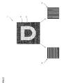
- FIG. 1 is a view illustrating the relief structure according to an embodiment of the present invention as viewed in a predetermined direction.
- FIG. 2 is a view illustrating the relief structure according to the present embodiment as viewed in a direction rotated by 90° with respect to the predetermined direction.
- a relief structure 1 includes a first area 1a constituting a background and a second area 1b constituting a character, as illustrated in FIG. 1 .
- the first area 1a includes a first grating 11 which is a vertical grating
- the second area 1b includes a second grating 12 which is a lateral grating obtained by rotating the vertical grating by 90°.
- the first grating 11 has a grating pitch of 370 nm and a depth of 100 nm and constitutes the first area 1a which looks red in the state illustrated in FIG. 1 .
- the second grating 12 has a grating pitch of 370 nm and a depth of 100 nm and constitutes the second area 1b which looks green in the state illustrated in FIG. 1 .
- the first grating 11 When the thus formed relief structure 1 is rotated by 90° from the state illustrated in FIG. 1 to the state illustrated in FIG. 2 , the first grating 11 is turned into a lateral grating, and the second grating 12 is turned into a vertical grating which is at an angle of 90° with respect to the lateral grating.
- the first grating 11 constitutes the first area 1a which looks green
- the second area 1b constitutes the second grating 12 which looks red.
- the first and second gratings 11 and 12 are made to look red and green; alternatively, however, the first and second gratings 11 and 12 may be made to look like other colors by adjusting the grating pitch and depth.
- the grating pitch is preferably set to a length equal to or less than the wavelength (e.g., 500 nm) of a visible light.
- a structure that scatters the reflected light is employed.
- a structure using a diffusion layer has conventionally been used; however, in such a structure, the thickness and the number of materials to be used are increased, resulting in increase in cost.
- a grating structure is used to scatter the reflected light. The following describes the scattering structure.
- a grating is formed on a Fourier transformation pattern or the like to form a scattering structure part, whereby and diffusion functions can be realized by a relief shape alone.
- the material of the high refractive index layer is not limited to zinc sulfide (ZnS), but may be any high refractive index material such as titanium oxide.
- ZnS zinc sulfide
- a heat seal layer 40 is formed on the high refractive index layer 30 as an adhesive layer.
- a relief structure transfer foil when the relief structure 1, high refractive index layer 30, and heat seal layer 40 are formed on a base material, a relief structure transfer foil can be obtained.
- the heat seal layer 40 of the relief structure transfer foil is brought into contact with the adherend 60, followed by peeling-off of the base material, whereby the security medium 100 can be obtained.
- a peeling layer may be provided between the base material and the relief structure 1.
- the security medium 100 and relief structure transfer foil described above are not limited to the above configuration, but another configuration may be added thereto when needed.
- the Fourier transformation pattern may be formed according to the method described in JP 2001-337584A or JP 2011-123266A . Further, as described in JP 2007-15196A , the relief structure 1 may be formed so as to allow observation of a predetermined image when a light from a point light source directly incident on the relief structure 1 applied with the Fourier transformation pattern or incident thereon after once reflected is observed through the relief structure 1, or when a laser light transmitted through the relief structure 1 or a laser light transmitted through the relief structure 1 and then reflected is observed.
- FIG. 4 illustrates the grating structure part including the scattering structure part according to a first embodiment.
- the grating is formed according to phase information of the Fourier transformation pattern, so that it is possible to form the grating including the scattering structure part in a single process without addition of a diffusion layer.
- a relief structure having a simple structure, capable of being manufactured with ease and at low cost, and having improved visibility.
- FIG. 5 illustrates the grating structure part including the scattering structure part according to a second embodiment.
- the grating structure part 10 according to the second embodiment includes a non-grating part in at least a part of the first and second unit structure parts 10a and 10b.
- the first unit structure part 10a is formed at the phase 0 part
- the non-grating part 10c where no grating is formed is set at the phase ⁇ part, as illustrated in FIG. 5 .
- the scattering structure part is constituted by the first unit structure part 10a, second unit structure part 10b, and non-grating part 10c.
- the non-grating part 10c may be provided in at least a part of the first and second unit structure parts 10a and 10b.
- the grating is formed according to phase information of the Fourier transformation pattern, so that it is possible to form the grating including the scattering structure part in a single process without addition of a diffusion layer.
- a relief structure having a simpler structure, capable of being manufactured with ease and at low cost, and having improved visibility.
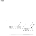
- FIG. 6 illustrates the grating structure part including the scattering structure part according to a third embodiment.
- the grating structure part 10 includes the first unit structure part 10a and the second unit structure part 10b.
- the first unit structure part 10a and the second unit structure part 10b are formed so as to be shifted in the grating depth direction according to phase information of the Fourier transformation pattern and thus to have different shapes from each other, whereby the scattering structure part is obtained.
- the first unit structure part 10a is formed at the phase 0 part
- the second unit structure part 10b different in shape from the first unit structure part 10a is formed at the phase ⁇ part by shifting the second unit structure part 10b by, e.g., 90 nm in the depth direction, as illustrated in FIG. 6 .
- the grating is formed according to phase information of the Fourier transformation pattern 20, so that it is possible to form the grating including the scattering structure part in a single duplication process without addition of a diffusion layer.
- a relief structure having a simple structure, capable of being manufactured with ease and at low cost, and having improved visibility.
- FIG. 7 illustrates the grating structure part including the scattering structure part according to another embodiment.
- the grating is formed on a scattering pattern 50.
- the scattering pattern 50 has a structure in which minute convex parts 51 formed on the surface thereof are used as scattering elements.
- the grating structure is formed only on the upper surface of the convex part 51 in the example of FIG. 7 , it may be formed on a concave part 52. That is, the grating structure may be formed on at least one of the convex part 51 and concave part 52.
- the grating is formed on the scattering pattern 50, so that it is possible to form the grating including the scattering structure part in a single process without addition of a diffusion layer.
- a relief structure having a simple structure, capable of being manufactured with ease and at low cost, and having improved visibility.
- the relief structure 1 includes the grating structure part 10 having the grating formed at a predetermined angle, and the grating structure part 10 includes the scattering structure part 20 or 50 having a light scattering property.
- the relief structure 1 includes the grating structure part 10 having the grating formed at a predetermined angle, and the grating structure part 10 includes the scattering structure part 20 or 50 having a light scattering property.
- the grating structure part 10 includes the first unit structure part 10a and the second unit structure part 10b having a different configuration from that of the first unit structure part 10a, and the scattering structure part 20 or 50 is formed so as to produce a scattering effect by the different structures of the first unit structure part 10a and second unit structure part 10b.
- the first unit structure part 10a and second unit structure part 10b are formed according to phase information of the Fourier transformation pattern, allowing further improvement in visibility.
- the second unit structure part 10b is formed such that at least a part thereof is two-dimensionally shifted from the first unit structure part 10a.
- At least one of the first and second unit structure parts 10a and 10b has the non-grating part in at least a part thereof.
- the relief structure 1 in the relief structure 1 according to the present embodiment, at least a part of the second unit structure part 10b is different in shape from the first unit structure part 10a.
- a relief structure having a simpler structure, capable of being manufactured with ease and at low cost, and having improved visibility.
- the grating structure part 10 includes the first area 1a having the first grating 11 formed at a predetermined angle and the second area 1b having the second grating 12 rotated by a predetermined angle with respect to the first grating 11, allowing further improvement in visibility.
- the security medium according to the present embodiment includes the relief structure 1, the high refractive index layer 30 formed on the surface of the relief structure 1, the heat seal layer 40 formed on the surface of the high refractive index layer 30.
Landscapes
- Physics & Mathematics (AREA)
- General Physics & Mathematics (AREA)
- Optics & Photonics (AREA)
- Engineering & Computer Science (AREA)
- Manufacturing & Machinery (AREA)
- Credit Cards Or The Like (AREA)
- Diffracting Gratings Or Hologram Optical Elements (AREA)
- Optical Elements Other Than Lenses (AREA)
- Burglar Alarm Systems (AREA)
- Holo Graphy (AREA)
Abstract
Description
- The present invention relates to a relief structure which is stuck or transferred to an article to prevent the counterfeiting of the article and a security medium having the relief structure.
- There is disclosed a subtractive color filter that changes its color depending on an observation direction using a zero-order diffraction light (see Patent Literature 1).
- Patent Literature 1:
JP-T 58-500916 - However, when the structure disclosed in
Patent Literature 1 is observed as it is, reflected light becomes so bright that the angular range over which a red or green color can be observed is narrow. - The object of the present invention is to provide a relief structure having a simple structure, capable of being manufactured with ease and at low cost, and capable of improving visibility, and a security medium having the relief structure.
- To attain the above object, a relief structure according to an embodiment of the present invention includes a grating structure part having a grating formed at a predetermined angle, wherein the grating structure part includes a scattering structure part having a light scattering property.
- Further, in the relief structure according to an embodiment of the present invention, the grating structure part includes a first unit structure part and a second unit structure part having a different configuration from that of the first unit structure part, and the scattering structure part is formed so as to produce a scattering effect by the different structures of the first unit structure part and second unit structure part.
- Further, in the relief structure according to an embodiment of the present invention, the first unit structure part and the second unit structure part are formed according to phase information of a Fourier transformation pattern.
- Further, in the relief structure according to an embodiment of the present invention, the second unit structure part is formed such that at least a part thereof is two-dimensionally shifted from the first unit structure part.
- Further, in the relief structure according to an embodiment of the present invention, at least one of the first and second unit structure parts has the non-grating part in at least a part thereof.
- Further, in the relief structure according to an embodiment of the present invention, at least a part of the second unit structure part is different in shape from the first unit structure part.
- Further, in the relief structure according to an embodiment of the present invention, the grating structure part includes a first area having a first grating formed at a predetermined angle and a second area having a second grating rotated by a predetermined angle with respect to the first grating.
- A security medium according to an embodiment of the present invention includes:
- the relief structure;
- a refractive index layer formed on the surface of the relief structure; and
- an adhesive layer formed on the surface of the refractive index layer.
- A security document according to an embodiment of the present invention includes the relief structure.
- According to the present invention, there can be provided a relief structure having a simple structure, capable of being manufactured with ease and at low cost, and capable of improving visibility, and a security medium having the relief structure.
-
-
FIG. 1 is a view illustrating a relief structure according to an embodiment of the present invention as viewed in a predetermined direction; -
FIG. 2 is a view illustrating the relief structure according to the present embodiment as viewed in a direction rotated by 90° with respect to the predetermined direction; -
FIG. 3 illustrates an example of a security medium including the relief structure according to the present embodiment in which a grating is formed according to phase information of a Fourier transformation pattern; -
FIG. 4 illustrates a grating structure part including a scattering structure part according to a first embodiment; -
FIG. 5 illustrates the grating structure part including the scattering structure part according to a second embodiment; -
FIG. 6 illustrates the grating structure part including the scattering structure part according to a third embodiment; and -
FIG. 7 illustrates the grating structure part including the scattering structure part according to another embodiment. - A relief structure according to an embodiment of the present invention will be described below with reference to the accompanying drawings.
-
FIG. 1 is a view illustrating the relief structure according to an embodiment of the present invention as viewed in a predetermined direction.FIG. 2 is a view illustrating the relief structure according to the present embodiment as viewed in a direction rotated by 90° with respect to the predetermined direction. - For example, in the present embodiment, a
relief structure 1 includes afirst area 1a constituting a background and asecond area 1b constituting a character, as illustrated inFIG. 1 . In the state illustrated inFIG 1 , thefirst area 1a includes afirst grating 11 which is a vertical grating, and thesecond area 1b includes asecond grating 12 which is a lateral grating obtained by rotating the vertical grating by 90°. - The
first grating 11 has a grating pitch of 370 nm and a depth of 100 nm and constitutes thefirst area 1a which looks red in the state illustrated inFIG. 1 . Thesecond grating 12 has a grating pitch of 370 nm and a depth of 100 nm and constitutes thesecond area 1b which looks green in the state illustrated inFIG. 1 . - When the thus formed
relief structure 1 is rotated by 90° from the state illustrated inFIG. 1 to the state illustrated inFIG. 2 , thefirst grating 11 is turned into a lateral grating, and thesecond grating 12 is turned into a vertical grating which is at an angle of 90° with respect to the lateral grating. In this state illustrated inFIG. 2 , thefirst grating 11 constitutes thefirst area 1a which looks green, and thesecond area 1b constitutes thesecond grating 12 which looks red. - In the present embodiment, the first and
second gratings second gratings - When the thus formed
relief structure 1 is observed as it is, reflected light becomes so bright that the angular range over which the red or green color can be observed is narrow. Therefore, in the present embodiment, a structure that scatters the reflected light is employed. As the structure for scattering the reflected light, a structure using a diffusion layer has conventionally been used; however, in such a structure, the thickness and the number of materials to be used are increased, resulting in increase in cost. Thus, in the present embodiment, a grating structure is used to scatter the reflected light. The following describes the scattering structure. - In the
relief structure 1 according to the present embodiment, a grating is formed on a Fourier transformation pattern or the like to form a scattering structure part, whereby and diffusion functions can be realized by a relief shape alone. -
FIG. 3 illustrates an example of asecurity medium 100 including therelief structure 1 according to the present embodiment in which a grating is formed according to phase information of a Fourier transformation pattern. - In the
relief structure 1 included in thesecurity medium 100 according to the present embodiment, when agrating structure part 10 is formed according to phase information of aFourier transformation pattern 20, a part of thegrating structure part 10 is formed so as to have a different structure from that of the rest of thegrating structure part 10 to thereby form a scattering structure part having a scattering effect. A refractive index layer is vapor-deposited on the surface of the Fouriertransformation pattern 20 which thegrating structure part 10 is formed. For example, in the present embodiment, a highrefractive index layer 30 of zinc sulfide (ZnS) having a refractive index of 2.3 and a thickness of about 100 nm is deposited. The material of the high refractive index layer is not limited to zinc sulfide (ZnS), but may be any high refractive index material such as titanium oxide. For example, aheat seal layer 40 is formed on the highrefractive index layer 30 as an adhesive layer. - The
relief structure 1 and highrefractive index layer 30 are stuck to an adherend 60 through theheat seal layer 40. Examples of the adherend 60 include articles (i.e., also referred to as "security documents") requiring counterfeiting prevention, such as an ID, a certificate, a passport, a bill, a cash voucher, a passbook, a public deed, and a brand protection label. - Although not illustrated, when the
relief structure 1, highrefractive index layer 30, andheat seal layer 40 are formed on a base material, a relief structure transfer foil can be obtained. Theheat seal layer 40 of the relief structure transfer foil is brought into contact with the adherend 60, followed by peeling-off of the base material, whereby thesecurity medium 100 can be obtained. To facilitate the peeling-off of the base material of the relief structure transfer foil, a peeling layer may be provided between the base material and therelief structure 1. Thesecurity medium 100 and relief structure transfer foil described above are not limited to the above configuration, but another configuration may be added thereto when needed. - The Fourier transformation pattern may be formed according to the method described in
JP 2001-337584A JP 2011-123266A JP 2007-15196A relief structure 1 may be formed so as to allow observation of a predetermined image when a light from a point light source directly incident on therelief structure 1 applied with the Fourier transformation pattern or incident thereon after once reflected is observed through therelief structure 1, or when a laser light transmitted through therelief structure 1 or a laser light transmitted through therelief structure 1 and then reflected is observed. -
FIG. 4 illustrates the grating structure part including the scattering structure part according to a first embodiment. - The
grating structure part 10 according to the first embodiment includes a firstunit structure part 10a and a secondunit structure part 10b. The left-right or up-down position of the grating is two-dimensionally shifted between the firstunit structure part 10a and the secondunit structure part 10b in a plane constituting the grating according to phase information of the Fourier transformation pattern to thereby obtain the scattering structure part. For example, in thegrating structure part 10 according to the first embodiment, assuming that the phase of the Fourier transformation pattern has two values: 0 and π, the firstunit structure part 10a is formed at the phase 0 part, and the secondunit structure part 10b is formed at the phase π part by shifting the secondunit structure part 10b in the direction orthogonal to the grating line by a half of the grating pitch, as illustrated inFIG. 4 . - As described above, in the
relief structure 1 according to the present embodiment, the grating is formed according to phase information of the Fourier transformation pattern, so that it is possible to form the grating including the scattering structure part in a single process without addition of a diffusion layer. Thus, there can be provided a relief structure having a simple structure, capable of being manufactured with ease and at low cost, and having improved visibility. -
FIG. 5 illustrates the grating structure part including the scattering structure part according to a second embodiment. - The
grating structure part 10 according to the second embodiment includes a non-grating part in at least a part of the first and secondunit structure parts grating structure part 10 according to the second embodiment, assuming that the phase of the Fourier transformation pattern has two values: 0 and π, the firstunit structure part 10a is formed at the phase 0 part, and thenon-grating part 10c where no grating is formed is set at the phase π part, as illustrated inFIG. 5 . Thus, the scattering structure part is constituted by the firstunit structure part 10a, secondunit structure part 10b, andnon-grating part 10c. Thenon-grating part 10c may be provided in at least a part of the first and secondunit structure parts - As described above, in the
relief structure 1 according to the present embodiment, the grating is formed according to phase information of the Fourier transformation pattern, so that it is possible to form the grating including the scattering structure part in a single process without addition of a diffusion layer. Thus, there can be provided a relief structure having a simpler structure, capable of being manufactured with ease and at low cost, and having improved visibility. -
FIG. 6 illustrates the grating structure part including the scattering structure part according to a third embodiment. - The
grating structure part 10 according to the third embodiment includes the firstunit structure part 10a and the secondunit structure part 10b. The firstunit structure part 10a and the secondunit structure part 10b are formed so as to be shifted in the grating depth direction according to phase information of the Fourier transformation pattern and thus to have different shapes from each other, whereby the scattering structure part is obtained. For example, in thegrating structure part 10 according to the third embodiment, assuming that the phase of the Fourier transformation pattern has two values: 0 and π, the firstunit structure part 10a is formed at the phase 0 part, and the secondunit structure part 10b different in shape from the firstunit structure part 10a is formed at the phase π part by shifting the secondunit structure part 10b by, e.g., 90 nm in the depth direction, as illustrated inFIG. 6 . - As described above, in the
relief structure 1 according to the present embodiment, the grating is formed according to phase information of theFourier transformation pattern 20, so that it is possible to form the grating including the scattering structure part in a single duplication process without addition of a diffusion layer. Thus, there can be provided a relief structure having a simple structure, capable of being manufactured with ease and at low cost, and having improved visibility. -
FIG. 7 illustrates the grating structure part including the scattering structure part according to another embodiment. - In the
grating structure part 10 according to the embodiment illustrated inFIG. 7 , the grating is formed on ascattering pattern 50. Thescattering pattern 50 has a structure in which minuteconvex parts 51 formed on the surface thereof are used as scattering elements. Although the grating structure is formed only on the upper surface of theconvex part 51 in the example ofFIG. 7 , it may be formed on aconcave part 52. That is, the grating structure may be formed on at least one of theconvex part 51 andconcave part 52. - As described above, in the
relief structure 1 according to the present embodiment, the grating is formed on thescattering pattern 50, so that it is possible to form the grating including the scattering structure part in a single process without addition of a diffusion layer. Thus, there can be provided a relief structure having a simple structure, capable of being manufactured with ease and at low cost, and having improved visibility. - As described above, the
relief structure 1 according to the present embodiment includes thegrating structure part 10 having the grating formed at a predetermined angle, and thegrating structure part 10 includes thescattering structure part - Further, in the
relief structure 1 according to the present embodiment, thegrating structure part 10 includes the firstunit structure part 10a and the secondunit structure part 10b having a different configuration from that of the firstunit structure part 10a, and thescattering structure part unit structure part 10a and secondunit structure part 10b. Thus, there can be provided a relief structure having a simpler structure and capable of being manufactured with ease and at low cost. - The first
unit structure part 10a and secondunit structure part 10b are formed according to phase information of the Fourier transformation pattern, allowing further improvement in visibility. - Further, in the
relief structure 1 according to the present embodiment, the secondunit structure part 10b is formed such that at least a part thereof is two-dimensionally shifted from the firstunit structure part 10a. Thus, there can be provided a relief structure having a simpler structure, capable of being manufactured with ease and at low cost, and having improved visibility. - Further, in the
relief structure 1 according to the present embodiment, at least one of the first and secondunit structure parts - Further, in the
relief structure 1 according to the present embodiment, at least a part of the secondunit structure part 10b is different in shape from the firstunit structure part 10a. Thus, there can be provided a relief structure having a simpler structure, capable of being manufactured with ease and at low cost, and having improved visibility. - Further, in the
relief structure 1 according to the present embodiment, thegrating structure part 10 includes thefirst area 1a having thefirst grating 11 formed at a predetermined angle and thesecond area 1b having thesecond grating 12 rotated by a predetermined angle with respect to thefirst grating 11, allowing further improvement in visibility. - Further, the security medium according to the present embodiment includes the
relief structure 1, the highrefractive index layer 30 formed on the surface of therelief structure 1, theheat seal layer 40 formed on the surface of the highrefractive index layer 30. Thus, there can be provided a security medium having a simple structure, capable of being manufactured with ease and at low cost, and having improved visibility. - While the relief structure and security medium have been described by way of the several embodiments, the present invention is not limited to the above embodiments, and various combinations and modifications thereof are possible.
-
- 1:
- Relief structure
- 1a:
- First area
- 1b:
- Second area
- 11:
- First grating
- 12:
- Second grating
- 10:
- Grating structure part
- 10a:
- First unit structure part
- 10b:
- Second unit structure part
- 20:
- Fourier transformation pattern (scattering structure part)
- 30:
- High refractive index layer
- 40:
- Heat seal layer (adhesive layer)
- 50:
- Scattering pattern (scattering structure part)
- 100:
- Security medium
Claims (9)
- A relief structure characterized by comprising a grating structure part having a grating formed at a predetermined angle, wherein
the grating structure part includes a scattering structure part having a light scattering property. - The relief structure according to claim 1, characterized in that
the grating structure part includes a first unit structure part and a second unit structure part having a different configuration from that of the first unit structure part, and
the scattering structure part is formed so as to produce a scattering effect by the structures of the first unit structure part and second unit structure part different from each other. - The relief structure according to claim 2, characterized in that
the first unit structure part and second unit structure part are formed according to phase information of a Fourier transformation pattern. - The relief structure according to claim 2 or 3, characterized in that
the second unit structure part is formed such that at least a part thereof is two-dimensionally shifted from the first unit structure part. - The relief structure according to any one of claims 2 to 4, characterized in that
the first and second unit structure parts have the non-grating part in at least a part thereof. - The relief structure according to any one of claims 2 to 5, characterized in that
at least a part of the second unit structure part is different in shape from the first unit structure part. - The relief structure according to any one of claims 1 to 6, characterized in that
the grating structure part includes a first area having a first grating formed at a predetermined angle and a second area having a second grating rotated by a predetermined angle with respect to the first grating. - A security medium characterized by comprising:the relief structure as claimed in any one of claims 1 to 7;a refractive index layer formed on the surface of the relief structure; andan adhesive layer formed on the surface of the refractive index layer.
- A security document characterized by comprising the relief structure as claimed in any one of claims 1 to 8.
Applications Claiming Priority (2)
| Application Number | Priority Date | Filing Date | Title |
|---|---|---|---|
| JP2014218924 | 2014-10-28 | ||
| PCT/JP2015/080274 WO2016068143A1 (en) | 2014-10-28 | 2015-10-27 | Rugged structure and security medium |
Publications (2)
| Publication Number | Publication Date |
|---|---|
| EP3214469A1 true EP3214469A1 (en) | 2017-09-06 |
| EP3214469A4 EP3214469A4 (en) | 2018-07-25 |
Family
ID=55857478
Family Applications (1)
| Application Number | Title | Priority Date | Filing Date |
|---|---|---|---|
| EP15856069.8A Withdrawn EP3214469A4 (en) | 2014-10-28 | 2015-10-27 | Rugged structure and security medium |
Country Status (5)
| Country | Link |
|---|---|
| US (1) | US20170357036A1 (en) |
| EP (1) | EP3214469A4 (en) |
| JP (1) | JP6044815B2 (en) |
| CN (1) | CN107111019B (en) |
| WO (1) | WO2016068143A1 (en) |
Families Citing this family (1)
| Publication number | Priority date | Publication date | Assignee | Title |
|---|---|---|---|---|
| JP2019049621A (en) * | 2017-09-08 | 2019-03-28 | 大日本印刷株式会社 | Light modulation element and information recording medium |
Family Cites Families (27)
| Publication number | Priority date | Publication date | Assignee | Title |
|---|---|---|---|---|
| JP4377532B2 (en) * | 2000-07-11 | 2009-12-02 | 大日本印刷株式会社 | Latent image display medium and method for manufacturing latent image display medium |
| US7722194B2 (en) * | 2007-06-07 | 2010-05-25 | Seiko Epson Corporation | Optical element having a reflected light diffusing function and a polarization separation function and a projection display device |
| JP2009015305A (en) * | 2007-06-07 | 2009-01-22 | Seiko Epson Corp | Optical element and projection display device |
| CN100565251C (en) * | 2007-07-20 | 2009-12-02 | 苏州苏大维格光电科技股份有限公司 | An anti-counterfeit structure for card and identification method thereof |
| US8221963B2 (en) * | 2007-12-27 | 2012-07-17 | Seiko Epson Corporation | Method for producing fine structure |
| DE102008017652A1 (en) * | 2008-04-04 | 2009-10-08 | Leonhard Kurz Stiftung & Co. Kg | Security element and method for producing a security element |
| ES2620654T3 (en) * | 2008-04-18 | 2017-06-29 | Toppan Printing Co., Ltd. | Item marking material of marked items |
| DE102008024147B4 (en) * | 2008-05-19 | 2020-12-03 | Ovd Kinegram Ag | Optical security element |
| JP5316231B2 (en) * | 2009-06-04 | 2013-10-16 | 凸版印刷株式会社 | Display and printed information |
| EP2466345B1 (en) * | 2009-08-13 | 2021-11-03 | Toppan Printing Co., Ltd. | Image-displaying body and labeled article |
| JP5605538B2 (en) * | 2009-12-10 | 2014-10-15 | 大日本印刷株式会社 | Diffraction structure display |
| JP2012078447A (en) * | 2010-09-30 | 2012-04-19 | Toppan Printing Co Ltd | Display body and article with label |
| JP2012123102A (en) * | 2010-12-07 | 2012-06-28 | Toppan Printing Co Ltd | Display body and labeled article |
| JP2012208149A (en) * | 2011-03-29 | 2012-10-25 | Toppan Printing Co Ltd | Image display body and information medium |
| DE102011102999A1 (en) * | 2011-05-24 | 2012-11-29 | Leonhard Kurz Stiftung & Co. Kg | Foil and its production process |
| JP6013945B2 (en) * | 2012-03-21 | 2016-10-25 | Jxエネルギー株式会社 | Manufacturing method of device provided with substrate having concavo-convex pattern |
| JP2013242453A (en) * | 2012-05-22 | 2013-12-05 | Dainippon Printing Co Ltd | Uneven structure |
| JP6037103B2 (en) * | 2012-05-22 | 2016-11-30 | 大日本印刷株式会社 | Uneven structure |
| DE102012105571B4 (en) * | 2012-06-26 | 2017-03-09 | Ovd Kinegram Ag | Decorative element as well as security document with a decorative element |
| US9794256B2 (en) * | 2012-07-30 | 2017-10-17 | Box, Inc. | System and method for advanced control tools for administrators in a cloud-based service |
| DE102012108169A1 (en) * | 2012-09-03 | 2014-05-28 | Ovd Kinegram Ag | Security element as well as security document |
| JP6171291B2 (en) * | 2012-09-07 | 2017-08-02 | 凸版印刷株式会社 | True / false judgment method of display |
| CN103847289B (en) * | 2012-11-29 | 2016-03-23 | 中钞特种防伪科技有限公司 | There is the optical anti-counterfeit element reproducing hidden image and the product made with it |
| JP6237759B2 (en) * | 2013-02-21 | 2017-11-29 | 凸版印刷株式会社 | Display and labeled goods |
| JP2014240892A (en) * | 2013-06-11 | 2014-12-25 | 凸版印刷株式会社 | Optical element, and method for manufacturing transfer foil for forming optical element |
| CN203727019U (en) * | 2014-02-14 | 2014-07-23 | 上海人民印刷八厂 | Printing product with holographic patterns |
| JP6357892B2 (en) * | 2014-06-09 | 2018-07-18 | 凸版印刷株式会社 | Optical element |
-
2015
- 2015-10-27 CN CN201580058986.0A patent/CN107111019B/en active Active
- 2015-10-27 US US15/521,029 patent/US20170357036A1/en not_active Abandoned
- 2015-10-27 JP JP2016530030A patent/JP6044815B2/en active Active
- 2015-10-27 EP EP15856069.8A patent/EP3214469A4/en not_active Withdrawn
- 2015-10-27 WO PCT/JP2015/080274 patent/WO2016068143A1/en not_active Ceased
Also Published As
| Publication number | Publication date |
|---|---|
| US20170357036A1 (en) | 2017-12-14 |
| CN107111019B (en) | 2020-11-20 |
| CN107111019A (en) | 2017-08-29 |
| JP6044815B2 (en) | 2016-12-14 |
| JPWO2016068143A1 (en) | 2017-04-27 |
| WO2016068143A1 (en) | 2016-05-06 |
| EP3214469A4 (en) | 2018-07-25 |
Similar Documents
| Publication | Publication Date | Title |
|---|---|---|
| AU2014210898C1 (en) | Security devices and methods of manufacture thereof | |
| AU2014218193B2 (en) | Security device | |
| EP2960690B1 (en) | Display having a high anti-counterfeiting effect | |
| CN111032365B (en) | Optical safety components with visible reflections, manufacture of such components and safety documents equipped with such components | |
| EP3427968B1 (en) | Display | |
| ATE519606T1 (en) | SAFETY ELEMENT WITH AN OPTICALLY VARIABLE STRUCTURE | |
| CN105319628B (en) | A kind of optical anti-counterfeit element | |
| EP3114279B1 (en) | Method of forming a security document | |
| EP3210794B1 (en) | Multi-layered polymeric article, such as an identification document | |
| WO2012171061A1 (en) | Diffraction grating | |
| US20170357036A1 (en) | Relief structure and security medium | |
| WO2013161015A1 (en) | Diffraction grating recording medium | |
| JP6347336B2 (en) | Diffraction grating recording medium | |
| JP6399316B2 (en) | Diffraction grating recording medium | |
| WO2017001424A1 (en) | Multilayer light-diffracting structure | |
| EP3727872B1 (en) | Optical security component visible in reflection, manufacture of such a component, and secure document provided with such a component | |
| JP2013242454A (en) | Uneven structure | |
| EA201201055A1 (en) | PROTECTIVE ELEMENT FOR PROTECTION OF VALUABLE DOCUMENTS FROM FALSE AND COPYING, THE METHOD OF MANUFACTURING THE SPECIFIED PROTECTIVE ELEMENT AND THE METHOD OF VERIFICATION OF THE OBJECT TO BE PROTECTED, PROTECTING THE SUBSTITUTE CONTAINING THE PROTECTIVE CONTAINING THE PROTECTOR. |
Legal Events
| Date | Code | Title | Description |
|---|---|---|---|
| PUAI | Public reference made under article 153(3) epc to a published international application that has entered the european phase |
Free format text: ORIGINAL CODE: 0009012 |
|
| 17P | Request for examination filed |
Effective date: 20170427 |
|
| AK | Designated contracting states |
Kind code of ref document: A1 Designated state(s): AL AT BE BG CH CY CZ DE DK EE ES FI FR GB GR HR HU IE IS IT LI LT LU LV MC MK MT NL NO PL PT RO RS SE SI SK SM TR |
|
| AX | Request for extension of the european patent |
Extension state: BA ME |
|
| DAV | Request for validation of the european patent (deleted) | ||
| DAX | Request for extension of the european patent (deleted) | ||
| RIC1 | Information provided on ipc code assigned before grant |
Ipc: G02B 5/02 20060101ALI20180222BHEP Ipc: B42D 25/30 20140101ALI20180222BHEP Ipc: G02B 5/18 20060101AFI20180222BHEP |
|
| A4 | Supplementary search report drawn up and despatched |
Effective date: 20180625 |
|
| RIC1 | Information provided on ipc code assigned before grant |
Ipc: G02B 5/02 20060101ALI20180619BHEP Ipc: G02B 5/18 20060101AFI20180619BHEP Ipc: B42D 25/30 20140101ALI20180619BHEP |
|
| STAA | Information on the status of an ep patent application or granted ep patent |
Free format text: STATUS: THE APPLICATION HAS BEEN WITHDRAWN |
|
| 18W | Application withdrawn |
Effective date: 20200728 |