EP3214412A1 - Positioning unit - Google Patents
Positioning unit Download PDFInfo
- Publication number
- EP3214412A1 EP3214412A1 EP17000322.2A EP17000322A EP3214412A1 EP 3214412 A1 EP3214412 A1 EP 3214412A1 EP 17000322 A EP17000322 A EP 17000322A EP 3214412 A1 EP3214412 A1 EP 3214412A1
- Authority
- EP
- European Patent Office
- Prior art keywords
- sensor unit
- sensor
- unit
- switched
- switching output
- Prior art date
- Legal status (The legal status is an assumption and is not a legal conclusion. Google has not performed a legal analysis and makes no representation as to the accuracy of the status listed.)
- Granted
Links
- 230000005291 magnetic effect Effects 0.000 claims abstract description 27
- 239000003302 ferromagnetic material Substances 0.000 claims description 5
- 230000001419 dependent effect Effects 0.000 claims description 3
- 238000003466 welding Methods 0.000 claims 1
- 238000005259 measurement Methods 0.000 description 9
- 238000011161 development Methods 0.000 description 7
- 230000018109 developmental process Effects 0.000 description 7
- 238000011156 evaluation Methods 0.000 description 3
- 238000013507 mapping Methods 0.000 description 3
- 238000001514 detection method Methods 0.000 description 1
- 230000005611 electricity Effects 0.000 description 1
- 239000002828 fuel tank Substances 0.000 description 1
- 239000004065 semiconductor Substances 0.000 description 1
- 230000001960 triggered effect Effects 0.000 description 1
Images
Classifications
-
- G—PHYSICS
- G01—MEASURING; TESTING
- G01D—MEASURING NOT SPECIALLY ADAPTED FOR A SPECIFIC VARIABLE; ARRANGEMENTS FOR MEASURING TWO OR MORE VARIABLES NOT COVERED IN A SINGLE OTHER SUBCLASS; TARIFF METERING APPARATUS; MEASURING OR TESTING NOT OTHERWISE PROVIDED FOR
- G01D5/00—Mechanical means for transferring the output of a sensing member; Means for converting the output of a sensing member to another variable where the form or nature of the sensing member does not constrain the means for converting; Transducers not specially adapted for a specific variable
- G01D5/12—Mechanical means for transferring the output of a sensing member; Means for converting the output of a sensing member to another variable where the form or nature of the sensing member does not constrain the means for converting; Transducers not specially adapted for a specific variable using electric or magnetic means
- G01D5/14—Mechanical means for transferring the output of a sensing member; Means for converting the output of a sensing member to another variable where the form or nature of the sensing member does not constrain the means for converting; Transducers not specially adapted for a specific variable using electric or magnetic means influencing the magnitude of a current or voltage
- G01D5/142—Mechanical means for transferring the output of a sensing member; Means for converting the output of a sensing member to another variable where the form or nature of the sensing member does not constrain the means for converting; Transducers not specially adapted for a specific variable using electric or magnetic means influencing the magnitude of a current or voltage using Hall-effect devices
- G01D5/145—Mechanical means for transferring the output of a sensing member; Means for converting the output of a sensing member to another variable where the form or nature of the sensing member does not constrain the means for converting; Transducers not specially adapted for a specific variable using electric or magnetic means influencing the magnitude of a current or voltage using Hall-effect devices influenced by the relative movement between the Hall device and magnetic fields
-
- G—PHYSICS
- G01—MEASURING; TESTING
- G01D—MEASURING NOT SPECIALLY ADAPTED FOR A SPECIFIC VARIABLE; ARRANGEMENTS FOR MEASURING TWO OR MORE VARIABLES NOT COVERED IN A SINGLE OTHER SUBCLASS; TARIFF METERING APPARATUS; MEASURING OR TESTING NOT OTHERWISE PROVIDED FOR
- G01D5/00—Mechanical means for transferring the output of a sensing member; Means for converting the output of a sensing member to another variable where the form or nature of the sensing member does not constrain the means for converting; Transducers not specially adapted for a specific variable
- G01D5/12—Mechanical means for transferring the output of a sensing member; Means for converting the output of a sensing member to another variable where the form or nature of the sensing member does not constrain the means for converting; Transducers not specially adapted for a specific variable using electric or magnetic means
- G01D5/25—Selecting one or more conductors or channels from a plurality of conductors or channels, e.g. by closing contacts
- G01D5/251—Selecting one or more conductors or channels from a plurality of conductors or channels, e.g. by closing contacts one conductor or channel
- G01D5/2515—Selecting one or more conductors or channels from a plurality of conductors or channels, e.g. by closing contacts one conductor or channel with magnetically controlled switches, e.g. by movement of a magnet
Definitions
- the invention relates to a position determination unit.
- a sensor unit for determining a linear position along a route has a plurality of Hall switches arranged in a row along the path, a transmitter movable over the row of Hall switches, a plurality of resistors connected in series, and a voltage measuring unit, wherein one Hall switch each switchably grounds a voltage node located between each two resistors.
- the object of the invention is to provide a device which further develops the prior art.
- the object of the invention provides a position determining unit, wherein the position determining unit has a number of N, similar sensor units, a sensor and a current measuring unit arranged at predetermined intervals at positions along a preferably straight or annular path.
- the transmitter is movable along the track and has a first end and a length extending from the first end parallel to the track.
- the encoder comprises a ferromagnetic material.
- the measuring unit in order to provide a sensor signal dependent on the measuring signal of the magnetic field sensor, has at least one magnetic field sensor and is arranged with a lower side on an upper side of the carrier.
- each sensor unit is connected to a supply voltage.
- a first sensor unit is arranged at a beginning of the route and a last sensor unit at one end of the route.
- the first sensor unit is connected to a reference potential by means of the second supply voltage terminal, e.g. with a ground potential, and has a current consumption Isup.
- the second supply voltage terminals of the further sensor units are each connected to the switching output of the preceding sensor unit, wherein the respective further sensor unit can be switched on or off by means of the switching output of the preceding sensor unit and the respective further sensor unit has a current consumption Isup in the switched-on state.
- a current measuring unit is arranged before the first supply voltage connection of the first sensor unit or before the second supply voltage connection of the first sensor unit.
- the current consumption Isup of all switched sensor units contribute to a measured by means of the current measuring unit sum current Isum, wherein the sum current Isum is a multiple of the current consumption Isup and is proportional to a position of the first end of the encoder.
- the bias magnet-equipped sensor units detect a change in the bias magnetic field by a ferromagnetic material having donors.
- the sensor signal is detected by means of the at least one magnetic field sensor of the measuring unit.
- the accuracy of the measurement can be increased by using two magnetic field sensors. It is also possible to carry out differential measurements with two magnetic field sensors.
- the measuring unit is preferably designed as an integrated circuit on the surface of a semiconductor component.
- the cascade-like interconnection of the sensor units is often referred to as a daisy chain. While the first sensor unit is always in the switched-on state when the position-determining unit is started up, the following sensor units in the daisy chain arrangement are only switched on in each case due to a threshold value violation of the sensor signal of the immediately preceding sensor unit. The threshold value exceeding a sensor signal of the respective sensor unit is triggered by the encoder.
- summation current can be on the Number of sensor units switched on and thus to the position of the responsible for switching encoder to be closed.
- An advantage of the device according to the invention is that it is not necessary to communicate with the individual sensor units or that the output signals of the sensor units do not have to be evaluated, but the total current and the fixed positions of the sensor units already contain the information about the position of the transmitter. As a result, a complex circuit for address assignment and address output is unnecessary.
- position determination unit With the position determination unit according to the invention, path measurements over long ranges are possible, as are necessary, for example, for seat rails in cars or for level measurement in fuel tanks.
- the bias magnet of each sensor unit is arranged in a first direction before or after the measuring unit on the surface of the carrier in a first direction pointing from the beginning of the distance to the end of the distance, wherein the first pole and the second pole along the first Direction or perpendicular to the first direction are arranged one after the other.
- Succession of the poles along the first direction causes the first pole to be aligned with an end face to the measuring unit.
- a bias magnetic field parallel to the surface and extending on the surface of the measuring unit is generated.
- At least one differential measurement of the magnetic field that is to say the detection of changes in the magnetic field, is possible.
- the bias magnet of each sensor unit is disposed in a first direction adjacent to the measuring unit on the surface of the carrier from the beginning of the route to the end of the path, the first pole being disposed in front of the second pole in the first direction is, which is generated on the entire surface of the measuring unit parallel to the surface and to the first direction extending bias magnetic field.
- the bias magnet of each sensor unit is U-shaped with a first sidewall, a second sidewall parallel to the first, and one of the first and second sidewalls connecting bottom is formed, wherein the first side wall and a first part of the wall adjoining the first part of the bottom form the first pole and the second side wall and adjoining the second side wall second part of the bottom form the second pole, the carrier and the Measuring unit are arranged completely between the first and the second side wall and the surface of the carrier is aligned perpendicular to the first and the second side wall.
- a bias magnetic field running parallel to the surface and perpendicular to the side walls is formed on the entire surface of the magnetic field sensor.
- the on state of the switching output of each sensor unit is switched when a first threshold value is exceeded or the off state of the switching output of each sensor unit is switched when the first threshold value is undershot.
- the first sensor unit is always switched on, while all other sensor units are only switched on due to a threshold value violation of the sensor signal of an immediately preceding sensor unit. If the first end of the transmitter is moved beyond the first sensor unit, then the sensor signal exceeds the first threshold value and switches on the immediately following sensor unit. If the first end of the transmitter continues to move beyond the second sensor unit, the immediately following third sensor unit is switched on, etc.
- the encoder In order to be able to determine a position of the first end of the encoder, it must always be ensured in the non-inverting embodiment that the encoder has a sufficient length, so that the encoder always moves at least from the first end when moving along the entire distance extends beyond the first sensor unit, since otherwise all other sensor units are switched off - consequence of the so-called daisy-chain arrangement.
- the relative position-mapping current Ipwm is provided in another alternative embodiment by means of an analogue output controlled between a Isup and 2 * Isup by a digital-to-analog converter.
Landscapes
- Physics & Mathematics (AREA)
- General Physics & Mathematics (AREA)
- Transmission And Conversion Of Sensor Element Output (AREA)
- Measurement Of Length, Angles, Or The Like Using Electric Or Magnetic Means (AREA)
Abstract
Positionsbestimmungseinheit, aufweisend eine Anzahl von an Positionen entlang einer Strecke angeordneten, gleichartigen Sensoreinheiten und einen Geber, wobei jede Sensoreinheit einen Träger, einen ersten und zweiten Versorgungsspannungsanschluss, einen Schaltausgang, eine Messeinheit und einen zwei Pole umfassenden Bias-Magneten aufweist, wobei die Messeinheit auf dem Träger angeordnet ist und mindestens ein Magnetfeldsensor aufweist, wobei der Schaltausgang in Abhängigkeit von einer Schwellwertüberschreitung oder -unterschreitung eines Sensorsignals in einen on- oder einen off-Zustand geschaltet ist, wobei der erste Versorgungsspannungsanschluss jeder Sensoreinheit mit einer Versorgungsspannung verbunden ist, wobei eine erste Sensoreinheit an einem Anfang der Strecke und eine letzter Sensoreinheit an einem Ende der Strecke angeordnet ist, wobei der zweite Versorgungsspannungsanschluss der ersten Sensoreinheit mit einem Referenzpotential verbunden ist, der erste Sensoreinheit eine Stromaufnahme Isup aufweist, wobei der zweite Versorgungsspannungsanschluss jeder weiteren Sensoreinheit mit dem Schaltausgang der, von der ersten Sensoreinheit ausgehend, entlang der Strecke unmittelbar vorausgehenden Sensoreinheit verbunden ist, mittels des Schaltausgangs der vorausgehenden Sensoreinheit ein- oder ausschaltbar ist und im eingeschalteten Zustand eine Stromaufnahme Isup aufweist, wobei die Positionsbestimmungseinheit eine Strommesseinheit zur Ermittlung eines zu einer Position des Gebers proportionalen Summenstrom aufweist.A position determining unit comprising a number of similar sensor units located at positions along a path and a transmitter, each sensor unit comprising a carrier, first and second supply voltage terminals, a switching output, a measuring unit and a two pole bias magnet, the measuring unit comprising the carrier is arranged and at least one magnetic field sensor, wherein the switching output is switched in response to a threshold exceeding or falling below a sensor signal in an on or an off state, wherein the first supply voltage terminal of each sensor unit is connected to a supply voltage, wherein a first Sensor unit is disposed at a beginning of the route and a last sensor unit at one end of the route, wherein the second supply voltage terminal of the first sensor unit is connected to a reference potential, the first sensor unit a Current consumption Isup, wherein the second supply voltage terminal of each further sensor unit is connected to the switching output of, starting from the first sensor unit, along the track immediately preceding sensor unit, by means of the switching output of the preceding sensor unit is switched on or off and has a current consumption Isup in the on state wherein the position determining unit comprises a current measuring unit for determining a sum current proportional to a position of the encoder.
Description
Die Erfindung betrifft eine Positionsbestimmungseinheit.The invention relates to a position determination unit.
Aus der
Aus der
Vor diesem Hintergrund besteht die Aufgabe der Erfindung darin, eine Vorrichtung anzugeben, die den Stand der Technik weiterbildet.Against this background, the object of the invention is to provide a device which further develops the prior art.
Die Aufgabe wird durch eine Positionsbestimmungseinheit mit den Merkmalen des Patentanspruchs 1 gelöst. Vorteilhafte Ausgestaltungen der Erfindung sind Gegenstand von Unteransprüchen.The object is achieved by a position determination unit having the features of patent claim 1. Advantageous embodiments of the invention are the subject of dependent claims.
Der Gegenstand der Erfindung stellt eine Positionsbestimmungseinheit bereit, wobei die Positionsbestimmungseinheit eine Anzahl von N, in vorbestimmten Abständen an Positionen entlang einer vorzugsweise geraden oder ringförmigen Strecke angeordneten, gleichartigen Sensoreinheiten, einen Geber und eine Strommesseinheit aufweist.The object of the invention provides a position determining unit, wherein the position determining unit has a number of N, similar sensor units, a sensor and a current measuring unit arranged at predetermined intervals at positions along a preferably straight or annular path.
Der Geber ist entlang der Strecke beweglich und weist ein erstes Ende und ein von dem ersten Ende parallel zu der Strecke verlaufende Länge auf. Der Geber umfasst ein ferromagnetisches Material.The transmitter is movable along the track and has a first end and a length extending from the first end parallel to the track. The encoder comprises a ferromagnetic material.
Jeder Sensoreinheit weist einen Träger, einen Versorgungsspannungsanschluss, einen zweiten Versorgungsspannungsanschluss, einen Schaltausgang, eine Messeinheit mit einem Schaltausgang und einen Bias-Magneten mit einem ersten Pol und einem zweiten Pol auf.Each sensor unit has a carrier, a supply voltage terminal, a second supply voltage terminal, a switching output, a measuring unit with a switching output and a bias magnet having a first pole and a second pole.
Die Messeinheit, um ein von dem Messsignal des Magnetfeldsensor abhängiges Sensorsignal bereitzustellen, mindestens einen Magnetfeldsensor aufweist und mit einer Unterseite auf einer Oberseite des Trägers angeordnet ist.The measuring unit, in order to provide a sensor signal dependent on the measuring signal of the magnetic field sensor, has at least one magnetic field sensor and is arranged with a lower side on an upper side of the carrier.
und der Schaltausgang in Abhängigkeit von einer Schwellwertüberschreitung oder einer Schwellwertunterschreitung des Sensorsignals in einen on-Zustand oder einen off-Zustand geschaltet ist. Der erste Versorgungsspannungsanschluss jeder Sensoreinheit ist mit einer Versorgungsspannung verbunden. Eine erste Sensoreinheit ist an einem Anfang der Strecke angeordnet und eine letzter Sensoreinheit an einem Ende der Strecke.and the switching output is switched to an on state or an off state in response to a threshold overshoot or undershoot of the sensor signal. The first supply voltage terminal of each sensor unit is connected to a supply voltage. A first sensor unit is arranged at a beginning of the route and a last sensor unit at one end of the route.
Die erste Sensoreinheit ist mittels des zweiten Versorgungsspannungsanschlusses mit einem Referenzpotential verbunden, z.B. mit einem Massepotential, und weist eine Stromaufnahme Isup auf.The first sensor unit is connected to a reference potential by means of the second supply voltage terminal, e.g. with a ground potential, and has a current consumption Isup.
Die zweiten Versorgungsspannungsanschlüsse der weiteren Sensoreinheiten sind jeweils mit dem Schaltausgang der vorausgehenden Sensoreinheit verbunden, wobei die jeweilige weitere Sensoreinheit mittels des Schaltausgangs der vorausgehenden Sensoreinheit einschaltbar oder ausschalbar ist und die jeweilige weitere Sensoreinheit im eingeschalteten Zustand eine Stromaufnahme Isup aufweist.The second supply voltage terminals of the further sensor units are each connected to the switching output of the preceding sensor unit, wherein the respective further sensor unit can be switched on or off by means of the switching output of the preceding sensor unit and the respective further sensor unit has a current consumption Isup in the switched-on state.
Eine Strommesseinheit ist vor dem ersten Versorgungsspannungsanschluss der ersten Sensoreinheit oder vor dem zweiten Versorgungsspannungsanschluss der ersten Sensoreinheit angeordnet.A current measuring unit is arranged before the first supply voltage connection of the first sensor unit or before the second supply voltage connection of the first sensor unit.
Die Stromaufnahmen Isup aller eingeschalteten Sensoreinheiten tragen zu einem mittels der Strommesseinheit gemessenen Summenstrom Isum bei, wobei der Summenstrom Isum ein Vielfaches der Stromaufnahmen Isup beträgt und zu einer Position des ersten Endes des Gebers proportional ist.The current consumption Isup of all switched sensor units contribute to a measured by means of the current measuring unit sum current Isum, wherein the sum current Isum is a multiple of the current consumption Isup and is proportional to a position of the first end of the encoder.
Es sei angemerkt, dass die mit Bias-Magnet ausgestatteten Sensoreinheiten eine Änderung des Bias-Magnetfelds durch einen ferromagnetisches Material aufweisenden Geber detektieren.It should be noted that the bias magnet-equipped sensor units detect a change in the bias magnetic field by a ferromagnetic material having donors.
Detektiert wird das Sensorsignal mittels des mindestens einen Magnetfeldsensors der Messeinheit. Die Genauigkeit der Messung lässt sich durch den Einsatz von zwei Magnetfeldsensors erhöhen. Auch lassen sich mit zwei Magnetfeldsensoren differentielle Messungen durchführen. Die Messeinheit ist vorzugsweise als integrierte Schaltung an der Oberfläche eines Halbleiterbausteins ausgebildet.The sensor signal is detected by means of the at least one magnetic field sensor of the measuring unit. The accuracy of the measurement can be increased by using two magnetic field sensors. It is also possible to carry out differential measurements with two magnetic field sensors. The measuring unit is preferably designed as an integrated circuit on the surface of a semiconductor component.
Die kaskadenartige Verschaltung der Sensoreinheiten wird häufig auch als Daisy Chain bezeichnet. Während sich die erste Sensoreinheit bei Inbetriebnahme der Positionsbestimmungseinheit immer in dem eingeschalteten Zustand befindet, werden folgende Sensoreinheiten in der Daisy Chain Anordnung jeweils erst aufgrund einer Schwellwertüberschreitung des Sensorsignals der unmittelbar vorhergehenden Sensoreinheit eingeschaltet. Die Schwellwertüberschreitung eines Sensorsignals der jeweiligen Sensoreinheit wird durch den Geber ausgelöst.The cascade-like interconnection of the sensor units is often referred to as a daisy chain. While the first sensor unit is always in the switched-on state when the position-determining unit is started up, the following sensor units in the daisy chain arrangement are only switched on in each case due to a threshold value violation of the sensor signal of the immediately preceding sensor unit. The threshold value exceeding a sensor signal of the respective sensor unit is triggered by the encoder.
Für die Positionsbestimmung wird ausgenutzt, dass eine eingeschaltete Sensoreinheit im Unterschied zu einer ausgeschalteten Sensoreinheit eine von Null verschiedene Stromaufnahme aufweist. Anhand der Messung der Gesamtstromaufnahme, hier als Summenstrom bezeichnet, lässt sich auf die Anzahl der eingeschalteten Sensoreinheiten und damit auf die Position des für das Einschalten verantwortlichen Gebers geschlossen werden.For determining the position, use is made of the fact that, in contrast to a switched-off sensor unit, an activated sensor unit has a current consumption which is different from zero. On the basis of the measurement of the total current consumption, here referred to as summation current, can be on the Number of sensor units switched on and thus to the position of the responsible for switching encoder to be closed.
Ein Vorteil der erfindungsgemäßen Vorrichtung ist, dass nicht mit den einzelnen Sensoreinheiten kommuniziert werden muss bzw. nicht die Ausgangssignale der Sensoreinheiten ausgewertet werden müssen, sondern der Summenstrom und die festen Positionen der Sensoreinheiten bereits die Information über die Position des Gebers enthalten. Hierdurch erübrigt sich eine aufwändige Schaltung zur Adressvergabe und Adressausgabe.An advantage of the device according to the invention is that it is not necessary to communicate with the individual sensor units or that the output signals of the sensor units do not have to be evaluated, but the total current and the fixed positions of the sensor units already contain the information about the position of the transmitter. As a result, a complex circuit for address assignment and address output is unnecessary.
Mit der erfindungsgemäßen Positionsbestimmungseinheit sind Wegmessungen über lange Bereiche möglich, wie sie beispielsweise für Sitzschienen in Autos oder für die Füllstandsmessung in Kraftstofftanks notwendig sind.With the position determination unit according to the invention, path measurements over long ranges are possible, as are necessary, for example, for seat rails in cars or for level measurement in fuel tanks.
Gemäß einer ersten alternativen Ausführungsform ist der Bias-Magnet jeder Sensoreinheit in einer von dem Anfang der Strecke zu dem Ende der Strecke zeigenden ersten Richtung vor oder hinter der Messeinheit auf der Oberfläche des Trägers angeordnet, wobei der erste Pol und der zweite Pol entlang der ersten Richtung oder senkrecht zu der ersten Richtung nacheinander angeordnet sind.According to a first alternative embodiment, the bias magnet of each sensor unit is arranged in a first direction before or after the measuring unit on the surface of the carrier in a first direction pointing from the beginning of the distance to the end of the distance, wherein the first pole and the second pole along the first Direction or perpendicular to the first direction are arranged one after the other.
Durch die vorbeschriebene Anordnung der Bias-Magneten sind Messeinheiten und Bias-Magneten der Sensoreinheiten entlang der Strecke abwechselnd aufgereiht.Due to the above-described arrangement of the bias magnets, measuring units and bias magnets of the sensor units are alternately lined up along the route.
Ein Aufeinanderfolgen der Pole entlang der ersten Richtung bewirkt, dass der erste Pol mit einer Stirnseite zu der Messeinheit ausgerichtet ist. Hierdurch wird an der Oberfläche der der Messeinheit ein zu der Oberfläche paralleles und verlaufendes Bias-Magnetfeld erzeugt.Succession of the poles along the first direction causes the first pole to be aligned with an end face to the measuring unit. As a result, a bias magnetic field parallel to the surface and extending on the surface of the measuring unit is generated.
Mit dem Aufeinanderfolgen der Pole in einer senkrecht zu der ersten Richtung ausgerichteten zweiten Richtung, wird an der gesamten Oberfläche der Messeinheit ein parallel zu der zweiten Richtung und zu der Oberfläche verlaufendes Bias-Magnetfeld erzeugt. Durch die Umkehr des Magnetfelds bilden sich oberhalb bzw. an der Oberfläche der Messeinheit zwei Bereiche aus, wobei die Magnetfelder der Bereiche jeweils genau entgegengesetzt verlaufen.With the succession of the poles in a second direction oriented perpendicular to the first direction, a parallel to the second direction and extending to the surface on the entire surface of the measuring unit Bias magnetic field generated. As a result of the reversal of the magnetic field, two regions form above or on the surface of the measuring unit, with the magnetic fields of the regions respectively running exactly opposite.
Sind zwei Magnetfeldsensoren vorgesehen, wobei der erste Magnetfeldsensor in dem ersten Bereich und der zweite Magnetfeldsensor in dem zweiten Bereich angeordnet ist, lässt sich eine absolute Messung durchführen. Einflüsse durch äußere Magnetfelder, wie z.B: beliebige Störfelder werden unterdrückt.If two magnetic field sensors are provided, wherein the first magnetic field sensor is arranged in the first region and the second magnetic field sensor is arranged in the second region, an absolute measurement can be carried out. Influences due to external magnetic fields, such as: Any interference fields are suppressed.
Ohne eine Richtungsumkehr des Bias-Magnetfelds ist zumindest eine differentielle Messung des Magnetfelds, also das Erfassen von Änderungen des Magnetfelds möglich.Without reversing the direction of the bias magnetic field, at least one differential measurement of the magnetic field, that is to say the detection of changes in the magnetic field, is possible.
In einer zweiten alternativen Ausführungsform ist der Bias-Magnet jeder Sensoreinheit in einer von dem Anfang der Strecke zu dem Ende der Strecke zeigenden ersten Richtung neben der Messeinheit auf der Oberfläche des Trägers angeordnet, wobei der erste Pol in der ersten Richtung vor dem zweiten Pol angeordnet ist, wodurch an der gesamten Oberfläche der Messeinheit ein parallel zu der Oberfläche und zu der ersten Richtung verlaufendes Bias-Magnetfeld erzeugt wird.In a second alternative embodiment, the bias magnet of each sensor unit is disposed in a first direction adjacent to the measuring unit on the surface of the carrier from the beginning of the route to the end of the path, the first pole being disposed in front of the second pole in the first direction is, which is generated on the entire surface of the measuring unit parallel to the surface and to the first direction extending bias magnetic field.
Gemäß einer dritten alternativen Ausführungsform ist der Bias-Magnet jeder Sensoreinheit U-förmig mit zwei parallel zueinander verlaufende Seitenwänden und einem die zwei Seitenwände verbindenden Boden ausgebildet, wobei die beiden Seitenwände und ein sich an die Seitenwände anschließender Teil des Bodens den ersten Pol bilden und ein von den Seitenwänden abgewandter zweiter Teil des Bodens den zweiten Pol bildet, der Träger und die Messeinheit vollständig zwischen den Seitenwänden angeordnet sind und die Oberfläche des Trägers senkrecht zu den Seitenwänden ausgerichtet ist.According to a third alternative embodiment, the bias magnet of each sensor unit is U-shaped with two mutually parallel side walls and a bottom connecting the two side walls, wherein the two side walls and adjoining the side walls of the bottom form the first pole and a second side of the bottom facing away from the side walls forms the second pole, the carrier and the measuring unit are arranged completely between the side walls and the surface of the carrier is aligned perpendicular to the side walls.
In einer vierten alternativen Ausführungsform ist der Bias-Magnet jeder Sensoreinheit U-förmig mit einer ersten Seitenwand, einer parallel zu der ersten verlaufenden zweiten Seitenwand und einem die erste und die zweite Seitenwand verbindenden Boden ausgebildet ist, wobei die erste Seitenwand und ein sich an die erste Seitenwand anschließender erster Teil des Bodens den ersten Pol bilden und die zweite Seitenwand und ein sich an die zweite Seitenwand anschließender zweiter Teil des Bodens den zweiten Pol bilden, der Träger und die Messeinheit vollständig zwischen der ersten und der zweiten Seitenwand angeordnet sind und die Oberfläche des Trägers senkrecht zu der ersten und der zweiten Seitenwand ausgerichtet ist. Hierdurch bildet sich an der gesamten Oberfläche des Magnetfeldsensors ein parallel zu der Oberfläche und senkrecht zu den Seitenwänden verlaufendes Bias-Magnetfeld aus.In a fourth alternative embodiment, the bias magnet of each sensor unit is U-shaped with a first sidewall, a second sidewall parallel to the first, and one of the first and second sidewalls connecting bottom is formed, wherein the first side wall and a first part of the wall adjoining the first part of the bottom form the first pole and the second side wall and adjoining the second side wall second part of the bottom form the second pole, the carrier and the Measuring unit are arranged completely between the first and the second side wall and the surface of the carrier is aligned perpendicular to the first and the second side wall. As a result, a bias magnetic field running parallel to the surface and perpendicular to the side walls is formed on the entire surface of the magnetic field sensor.
In einer weiteren alternativen Ausführungsform ist der on-Zustand des Schaltausgangs jeder Sensoreinheit bei Überschreiten eines ersten Schwellwerts geschaltet bzw. der off-Zustand des Schaltausgangs jeder Sensoreinheit bei Unterschreiten des ersten Schwellwerts geschaltet. Die Länge des Gebers erstreckt sich von dem ersten Ende des Gebers mindestens bis zu der ersten Sensoreinheit, wobei die Position des ersten Endes des Gebers im Bereich der Position Pm des m-ten Sensoreinheit Sm einem Summenstrom Isum = (m+1)*Isup entspricht.In a further alternative embodiment, the on state of the switching output of each sensor unit is switched when a first threshold value is exceeded or the off state of the switching output of each sensor unit is switched when the first threshold value is undershot. The length of the encoder extends from the first end of the encoder at least to the first sensor unit, wherein the position of the first end of the encoder in the region of the position Pm of the m-th sensor unit Sm corresponds to a total current Isum = (m + 1) * Isup ,
In der vorbeschriebenen nicht-invertierenden Ausführungsform ist die erste Sensoreinheit immer eingeschaltet, während alle weiteren Sensoreinheiten erst aufgrund einer Schwellwertüberschreitung des Sensorsignals einer unmittelbar vorausgehenden Sensoreinheit eingeschaltet werden. Wird das erste Ende des Gebers bis über die erste Sensoreinheit bewegt, so überschreitet das Sensorsignal den ersten Schwellwert und schaltet die unmittelbar folgende Sensoreinheit ein. Wird das erste Ende des Gebers weiter bis über die zweite Sensoreinheit bewegt, wird die unmittelbar folgende dritte Sensoreinheit eingeschaltet usw.In the above-described non-inverting embodiment, the first sensor unit is always switched on, while all other sensor units are only switched on due to a threshold value violation of the sensor signal of an immediately preceding sensor unit. If the first end of the transmitter is moved beyond the first sensor unit, then the sensor signal exceeds the first threshold value and switches on the immediately following sensor unit. If the first end of the transmitter continues to move beyond the second sensor unit, the immediately following third sensor unit is switched on, etc.
Um eine Position des ersten Endes des Gebers ermitteln zu können, muss in der nicht-invertierenden Ausführungsform immer gewährleistet sein, dass der Geber eine ausreichende Länge aufweist, so dass sich der Geber bei einer Bewegung entlang der gesamten Strecke immer von dem ersten Ende mindestens bis über die erste Sensoreinheit erstreckt, da ansonsten alle weiteren Sensoreinheiten abschaltet werden - Folge der sogenannten Daisy-Chain Anordnung.In order to be able to determine a position of the first end of the encoder, it must always be ensured in the non-inverting embodiment that the encoder has a sufficient length, so that the encoder always moves at least from the first end when moving along the entire distance extends beyond the first sensor unit, since otherwise all other sensor units are switched off - consequence of the so-called daisy-chain arrangement.
Die Position des ersten Endes des Gebers lässt sich zwischen einer Position 0 vor dem ersten Sensoreinheit (Schaltausgang der ersten Sensoreinheit im off-Zustand, Isum = 1*Isup) und einer Position PN-1 der vorletzten Sensoreinhelt (Schaltausgang der vorletzten Sensoreinheit im on-Zustand, Isum = N*Isup) bestimmen.The position of the first end of the encoder can be between a position 0 in front of the first sensor unit (switching output of the first sensor unit in the off state, Isum = 1 * Isup) and a position PN-1 of the penultimate sensor unit (switching output of the penultimate sensor unit in on State, Isum = N * Isup).
Gemäß einer Weiterbildung zur Erhöhung der Genauigkeit der Positionsbestimmung weist jeder Sensoreinheit mindestens einen ersten Schwellwert und einen zweiten Schwellwert auf und die Länge des Gebers von dem ersten Ende erstreckt sich mindestens bis zu dem ersten Sensoreinheit, wobei der zweite Schwellwert kleiner als der erste Schwellwert ist, der on-Zustand des Schaltausgang jeder Sensoreinheit bei Überschreiten des ersten Schwellwerts geschaltet ist, der off-Zustand des Schaltausgangs jeder Sensoreinheit bei Unterschreiten des zweiten Schwellwerts geschaltet ist und der on-Zustand des Schaltausgangs jeder Sensoreinheit für zwischen dem zweiten Schwellwert und dem ersten Schwellwert liegende Sensorsignale pulsweitenmoduliert geschaltet ist. Ein Tastgrad der Pulsweitenmodulation ist proportional zu dem Sensorsignal, wobei die Stromaufnahme Ipwm einer mit dem pulsweitenmoduliert geschalteten Schaltausgang verbundenen Sensoreinheit proportional zu dem Tastgrad und kleiner als die Stromaufnahme Isup im on-Zustand ist und eine Position des ersten Endes des Gebers im Bereich der Position des m-ten Sensoreinheits einem Summenstrom Isum = m*Isup + Ipwm entspricht.According to a development for increasing the accuracy of the position determination, each sensor unit has at least a first threshold value and a second threshold value, and the length of the encoder from the first end extends at least as far as the first sensor unit, wherein the second threshold value is smaller than the first threshold value, the on state of the switching output of each sensor unit is switched when the first threshold value is exceeded, the off state of the switching output of each sensor unit is switched below the second threshold value, and the on state of the switching output of each sensor unit is between between the second threshold value and the first threshold value Sensor signals is switched pulse width modulated. A duty cycle of the pulse width modulation is proportional to the sensor signal, the current consumption Ipwm of a connected to the pulse width modulated switching output sensor unit is proportional to the duty cycle and smaller than the current consumption Isup in the on state and a position of the first end of the encoder in the position of the m th sensor unit corresponds to a total current Isum = m * Isup + Ipwm.
Um eine zuverlässige Abbildung der Position mittels des pulsweitenmodulierten Schaltens der Sensoreinheit sicherzustellen, sollte jede Sensoreinheit eine nominale Stromaufnahme in möglichst kurzer Zeit erreichen. Die Zeit bis zum Erreichen einer nominalen Stromaufnahme sollte bevorzugt deutlich unter einer Periodendauer der Pulsweitenmodulation liegen. Hierdurch weist ein mittels des Schaltausgangs der unmittelbar vorausgehenden Sensoreinheit pulsweitenmoduliert geschalteter Sensoreinheit eine von Null verschiedene Stromaufnahme Ipwm auf, die jedoch kleiner als die Stromaufnahme Isup im vollständig angeschalteten Zustand ist.In order to ensure a reliable mapping of the position by means of the pulse-width-modulated switching of the sensor unit, each sensor unit should achieve a nominal current consumption in the shortest possible time. The time to reach a nominal current consumption should preferably be well below a period of the pulse width modulation. This indicates a by means of the switching output of the immediately preceding sensor unit pulse width modulated sensor unit connected to a non-zero power consumption Ipwm, which, however, is smaller than the current consumption Isup in the fully on state.
Die Stromaufnahme Ipwm ist proportional zu der Dauer des on-Zustands des pulsweitenmodulierten Schaltausgangs, d.h. Zu dem Tastgrad der Pulsweitenmodulation, wobei der Tastgrad das Verhältnis von on-Zustand zu off-Zustand innerhalb einer Periode der Pulsweitenmodulation angibt. Über den Tastgrad wird ein zwischen dem ersten Schwellwert und dem zweiten Schwellwert liegendes Sensorsignal bzw. die Höhe des Sensorsignals auf die Stromaufnahme Ipwm abgebildet und ist so durch Messung des Summenstroms bestimmbar.The current consumption Ipwm is proportional to the duration of the on state of the pulse width modulated switching output, i. To the duty cycle of the pulse width modulation, wherein the duty cycle indicates the ratio of on-state to off-state within a period of the pulse width modulation. By means of the duty cycle, a sensor signal lying between the first threshold value and the second threshold value or the height of the sensor signal is mapped onto the current consumption Ipwm and can thus be determined by measuring the total current.
In der pulsweitenmodulierten, nicht-invertierenden Ausführungsform setzt sich der Summenstrom aus einem ganzzahligen Vielfachen der Stromaufnahme Isup für alle vollständig eingeschalteten Sensoreinheiten und gegebenenfalls einem Anteil Ipwm mit 0<Ipwm<Isup einer pulsweitenmoduliert geschalteten Sensoreinheit zusammen. Neben einer von dem ganzzahligen Vielfachen gelieferten absoluten Position auf einer von den Sensorabständen gerasterten Skala erhält man somit mittels des Rests eine zweite Position, wobei die zweite Position eine relative Positionsinformation auf einer feineren Skala enthält.In the pulse-width-modulated, non-inverting embodiment, the total current is composed of an integral multiple of the current consumption Isup for all completely switched-in sensor units and optionally a component Ipwm with 0 <Ipwm <Isup of a pulse width modulated sensor unit. In addition to an absolute position provided by the integer multiple on a scale scanned by the sensor spacings, a second position is thus obtained by means of the remainder, the second position containing relative position information on a finer scale.
Für die Auswertung wird das PWM Signal beispielsweise über einen Tiefpass-Filter in einen linearen Strom- bzw. Spannungslevel gewandelt, z.B. mittels eines Shunt-Widerstands und kann beispielsweise reale Werte zwischen 0 und 1 mit einer Auflösung von 8 bis 16 Bit einnehmen. Die mittels des PWM Signal bestimmte relative Position wird somit in einem analogen Modus bestimmt, während die erste absolute Position in einem digitalen Modus (ganzzahliges Vielfaches) ermittelt wird.For the evaluation, the PWM signal is converted, for example via a low-pass filter in a linear current or voltage level, for example by means of a shunt resistor and can, for example, take real values between 0 and 1 with a resolution of 8 to 16 bits. The relative position determined by means of the PWM signal is thus determined in an analog mode, while the first absolute position is determined in a digital mode (integer multiple).
Alternativ sind die Sensoreinheiten so ausgelegt, dass jeder Sensoreinheit für zwischen dem ersten und dem zweiten Sensorsignal liegende Sensorsignale die eigene Stromaufnahme per Pulsweitenmodulation zwischen Isup und 2*Isup steuert, anstatt den Schaltausgang pulsweitenmoduliert zu Schalten. Hierdurch wird die relative Position des ersten Endes des Gebers über einem m-ten Sensoreinheit durch Pulsweitenmodulation der Stromaufnahme der m-ten Sensoreinheit und nicht durch die Stromaufnahme der (m+1)-ten Sensoreinheit abgebildet. An der weiteren Auswertung ändert sich jedoch nichts.Alternatively, the sensor units are designed so that each sensor unit for sensor signals lying between the first and the second sensor signal controls its own current consumption by pulse width modulation between Isup and 2 * Isup, instead of switching the switching output pulse width modulated. As a result, the relative position of the first end of the transmitter over an mth sensor unit by pulse width modulation of the current consumption of the mth sensor unit and not by the current consumption of the (m + 1) -th sensor unit is displayed. At the further evaluation, however, nothing changes.
Anstatt den zusätzlichen Strom Ipwm durch eine Pulsweitenmodulation der Stromaufnahme der Sensoreinheit zu erzeugen, wird der die relative Position abbildende Strom Ipwm in einer weiteren alternativen Ausführungsform mittels eines von einem Digital-Analog-Wandler zwischen zwischen Isup und 2*Isup geregelten Analogausgangs bereitgestellt.Instead of generating the additional current Ipwm by a pulse width modulation of the current consumption of the sensor unit, the relative position-mapping current Ipwm is provided in another alternative embodiment by means of an analogue output controlled between a Isup and 2 * Isup by a digital-to-analog converter.
In einer zweiten alternativen Ausführungsform ist der off-Zustand des Schaltausgangs jeder Sensoreinheit bei Überschreitung eines ersten Schwellwerts geschaltet, der on-Zustand des Schaltausgangs jeder Sensoreinheit bei Unterschreiten des ersten Schwellwerts geschaltet und der Geber erstreckt sich von dem ersten Ende zumindest entlang eines Teilbereichs der Strecke in Richtung der letzten Sensoreinheit, wobei eine Position des ersten Endes des Gebers im Bereich der Position der m-ten Sensoreinheit einem Summenstrom Isum = m*Isup entspricht.In a second alternative embodiment, the off state of the switching output of each sensor unit is switched when a first threshold value is exceeded, the on state of the switching output of each sensor unit is switched below the first threshold value, and the transmitter extends from the first end along at least part of the distance in the direction of the last sensor unit, wherein a position of the first end of the transmitter in the region of the position of the m-th sensor unit corresponds to a total current Isum = m * Isup.
In der invertierenden Ausführungsform sind in Abwesenheit des Gebers alle Sensoreinheiten eingeschaltet, da für alle Sensorsignale eine Schwellwertunterschreitung vorliegt. Der Geber bewirkt ein Ausschalten der Sensoreinheiten, wobei der Geber in der invertierenden Ausführungsform eine kurze Länge aufweisen kann, wobei sich die Länge von dem ersten Ende in Richtung der letzten Sensoreinheit erstreckt. Die Länge des Gebers muss sich lediglich ausreichen, um eine Schwellwertüberschreitung innerhalb der Sensoreinheit zu bewirken, wenn sich der Geber über dem Sensoreinheit befindet.In the inverting embodiment, all sensor units are switched on in the absence of the encoder, since there is a threshold value undershooting for all sensor signals. The encoder causes the sensor units to be switched off, wherein the encoder in the inverting embodiment can have a short length, the length extending from the first end towards the last sensor unit. The length of the encoder only has to be sufficient to cause a threshold value to be exceeded within the sensor unit when the encoder is located above the sensor unit.
Befindet sich das erste Ende über der ersten Sensoreinheit, so detektiert der ersten Sensoreinheit eine Grenzwertüberschreitung und der Schaltausgang der ersten Sensoreinheit ist in den off-Zustand geschaltet, so dass alle folgenden Sensoreinheiten ausgeschaltet werden. Bewegt sich das erste Ende des Gebers über die zweite Sensoreinheit, so detektiert die erste Sensoreinheit eine Schwellwertunterschreitung und schaltet die unmittelbar folgende zweite Sensoreinheit ein. Somit sind immer alle aufeinanderfolgenden Sensoreinheiten von dem ersten Sensoreinheit bis zu der Sensoreinheit eingeschaltet, über der sich das erste Ende des Gebers befindet. Das mittels des gemessenen Summenstroms bestimmbare Vielfache der Stromaufnahme gibt somit die Nummer der Sensoreinheit in der Reihe der entlang der Strecke angeordneten Sensoreinheiten an, über dem sich das erste Ende des Gebers befindet.If the first end is located above the first sensor unit, then the first sensor unit detects a limit value violation and the switching output of the first sensor unit is switched to the off state, so that all following sensor units are switched off. If the first end of the transmitter moves beyond the second sensor unit, then the first sensor unit detects a threshold value undershooting and switches on the immediately following second sensor unit. Thus, all successive sensor units are always switched from the first sensor unit to the sensor unit, above which the first end of the encoder is located. The multiple of the current consumption determinable by means of the measured sum current thus indicates the number of the sensor unit in the row of sensor units arranged along the path, above which the first end of the sensor is located.
Die Position des ersten Endes des Gebers lässt sich zwischen einer Position 1 über dem ersten Sensoreinheit (Schaltausgang der ersten Sensoreinheit im off-Zustand, Isum = 1*Isup) und einer Position PN der letzten Sensoreinheit (Schaltausgang der vorletzten Sensoreinheit im on-Zustand, Isum = N*Isup) bestimmen.The position of the first end of the encoder can be between a position 1 above the first sensor unit (switching output of the first sensor unit in the off state, Isum = 1 * Isup) and a position PN of the last sensor unit (switching output of the penultimate sensor unit in the on state, Isum = N * Isup).
In einer Weiterbildung zur Erhöhung der Genauigkeit der Positionsbestimmung weist jeder Sensoreinheit mindestens einen ersten Schwellwert und einen zweiten Schwellwert auf und der Geber erstreckt sich von dem ersten Ende zumindest entlang eines Teilbereichs der Strecke in Richtung der letzten Sensoreinheit, wobei der zweite Schwellwert kleiner als der erste Schwellwert ist, der off-Zustand des Schaltausgangs jeder Sensoreinheit bei Überschreiten des ersten Schwellwerts geschaltet ist, der on-Zustand des Schaltausgangs jeder Sensoreinheit bei Unterschreiten des zweiten Schwellwerts geschaltet ist, der off-Zustand des Schaltausgangs jeder Sensoreinheit für zwischen dem ersten Schwellwert und dem zweiten Schwellwert liegende Sensorsignale pulsweitenmoduliert geschaltet ist, der Tastgrad der Pulsweitenmodulation umgekehrt proportional zu dem Sensorsignal ist, die Stromaufnahme Ipwm eine mit dem pulsweitenmoduliert geschalteten Schaltausgangs verbundenen Sensoreinheit proportional zu dem Tastgrad und kleiner als die Stromaufnahme Isup im on-Zustand ist, eine Position des Ersten Endes des Gebers im Bereich der Position der m-ten Sensoreinheit einem Summenstrom Isum = (m-1)*Isup + Ipwm entspricht.In a development for increasing the accuracy of the position determination, each sensor unit has at least a first threshold value and a second threshold value, and the transmitter extends from the first end at least along a partial area of the distance in the direction of the last sensor unit, wherein the second threshold value is smaller than the first one Threshold is, the off state of the switching output of each sensor unit is switched when the first threshold is exceeded, the on state of the switching output of each sensor unit is switched below the second threshold, the off state of the switching output of each sensor unit for between the first threshold and second threshold lying sensor signals is switched pulse width modulated, the duty cycle of the pulse width modulation is inversely proportional to the sensor signal, the current consumption Ipwm one with the pulse width modulated switched switching output connected sensor unit proportional to the duty cycle and smaller than the current consumption Isup in the on state, a position of the first end of the encoder in the region of the position of the m-th sensor unit corresponds to a total current Isum = (m-1) * Isup + Ipwm.
Die vorbeschriebene Ausführungsform stellt eine invertierende, pulsweitenmodulierte Ausführungsform dar, d.h. in Abwesenheit des Gebers sind alle Sensoreinheiten eingeschaltet und der Geber bewirkt ein Ausschalten der Sensoreinheiten, wobei eine Position innerhalb eines über einem Sensoreinheit befindlichen Bereich mittels der Pulsweitenmodulation aufgelöst wird. Entsprechend gelten die vorangegangenen Ausführungen hinsichtlich einer Pulsweitenmodulation des Signalausgangs der Sensoreinheiten und hinsichtlich eines invertierten Betriebs der Sensoreinheiten.The embodiment described above is an inverting, pulse width modulated embodiment, i. In the absence of the transmitter, all the sensor units are switched on and the transmitter causes the sensor units to be switched off, whereby a position within an area located above a sensor unit is resolved by means of the pulse width modulation. Accordingly, the preceding statements apply to a pulse width modulation of the signal output of the sensor units and with respect to an inverted operation of the sensor units.
Gemäß einer anderen Weiterbildung weist die Stromaufnahme Isup der Sensoreinheiten untereinander eine Varianz von maximal 10% auf und/oder die Stromaufnahme jeder Sensoreinheit ist stabilisiert oder getrimmt, um eine besonders zuverlässige, fehierfreie Positionsbestimmung sicherzusteiien. In einer weiteren Ausführungsform sind die Abstände zwischen Sensoreinheiten zur Vereinfachung der Auswertung gleich.According to another development, the current consumption Isup of the sensor units with each other has a variance of at most 10% and / or the current consumption of each sensor unit is stabilized or trimmed to ensure a particularly reliable, error-free position determination. In a further embodiment, the distances between sensor units are the same for the purpose of simplifying the evaluation.
Gemäß einer Weiterbildung ist das erste Ende des Gebers als Spitze oder als Kante ausgebildet und/oder ein Abstand des Gebers zu der Strecke ist entlang der gesamten Länge des Gebers konstant oder nimmt zumindest im Bereich des ersten Endes zu. Mittels eines sich verjüngenden ersten Endes oder eines von den Sensoreinheiten weg gebogenen ersten Endes lässt sich insbesondere die Genauigkeit der mittels Pulsweitenmodulation bestimmten relativen Position innerhalb eines über einem einzelnen Sensoreinheit befindlichen Bereichs erhöhen und eine Ausgangskennlinie linearisieren.According to a development, the first end of the transmitter is formed as a tip or edge and / or a distance of the encoder to the distance is constant along the entire length of the encoder or at least increases in the region of the first end. By means of a tapering first end or a first end bent away from the sensor units, it is possible in particular to increase the accuracy of the relative position determined by means of pulse width modulation within a region situated above a single sensor unit and to linearize an output characteristic.
In einer weiteren Ausführungsform sind die Sensoreinheiten Hall-Sensoren, wobei der mindestens eine Magnetfeldsensor eine lateral-messende Hall-Platte oder eine vertikal messende Hall-Platte ist. Geeignete Sensoreinheiten sind beispielsweise 3-Draht Hall Schalter oder 3-Draht Linear Sensoreinheiten mit einem Pulsweitenmodulationsausgang. Als Magnetfeldsensoren lassen sich auch magnetoresistive Sensoren verwenden.In a further embodiment, the sensor units are Hall sensors, wherein the at least one magnetic field sensor is a laterally measuring Hall plate or a vertically measuring Hall plate. Suitable sensor units are for example 3-wire Hall switch or 3-wire linear sensor units with a pulse width modulation output. As magnetic field sensors can also be used magnetoresistive sensors.
Der Schaltausgang weist gemäß einer Weiterbildung einen open-drain Transistor auf, wobei eine Strombelastbarkeit des open-drain Ausgangs des open-drain Transistor bevorzugt mindestens 100mA und/oder ein Eingangswiderstand des open-drain Transistors bevorzugt höchstens 100mΩ beträgt. Um auch bei einer hohen Anzahl von Sensoreinheiten den Beitrag aller eingeschalteten Sensoreinheiten zu dem zu messenden Summenstrom sicherzustellen, muss die Strombelastbarkeit der open-drain Transistoren der Sensoreinheiten möglichst hoch sein. Um auch bei einer hohen Anzahl von Sensoreinheiten noch eine möglichst niedrige Versorgungsspannung nutzen zu können, darf der Eingangswiderstand des open-drain Transistors nicht zu hoch sein.According to a further development, the switching output has an open-drain transistor, wherein a current-carrying capacity of the open-drain output of the open-drain transistor is preferably at least 100 mA and / or an input resistance of the open-drain transistor is preferably at most 100 mA. In order to ensure the contribution of all switched-sensor units to the measured total current even with a high number of sensor units, the current carrying capacity of the open-drain transistors of the sensor units must be as high as possible. In order to still be able to use as low a supply voltage as possible even with a large number of sensor units, the input resistance of the open-drain transistor must not be too high.
In einer kostengünstigeren Ausführungsform ist die letzte Sensoreinheit durch einen Widerstand ersetzt. Ein definierter Stromlevel wird durch Anpassung des Werts des Widerstands an die Versorgungsspannung erreicht.In a more cost effective embodiment, the last sensor unit is replaced by a resistor. A defined current level is achieved by adjusting the value of the resistor to the supply voltage.
Die Erfindung wird nachfolgend unter Bezugnahme auf die Zeichnungen näher erläutert. Hierbei werden gleichartige Teile mit identischen Bezeichnungen beschriftet. Die dargestellten Ausführungsformen sind stark schematisiert, d.h. die Abstände und die lateralen und die vertikalen Erstreckungen sind nicht maßstäblich und weisen, sofern nicht anders angegeben, auch keine ableitbaren geometrischen Relationen zueinander auf. Darin zeigt:
- Figur 1
- eine schematische Ansicht einer ersten Ausführungsform einer erfindungsgemäßen Positionsbestimmungseinheit mit Sensoreinheiten in einer ersten Ausführungsform,
Figur 2- eine schematische Aufsicht eine in der ersten Ausführungsform Sensoreinheit,
- Figur 3
- eine zweite Ausführungsform eine Sensoreinheits,
Figur 4- eine dritte Ausführungsform einer Sensoreinheit,
Figur 5- eine vierte Ausführungsform einer Sensoreinheit,
- Figur 6
- eine schematische Ansicht auf eine zweite Ausführungsform einer erfindungsgemäßen Positionsbestimmungseinheit,
- Figur 7
- eine schematische Ansicht auf eine dritte Ausführungsform einer erfindungsgemäßen Positionsbestimmungseinheit,
- Figur 8
- eine schematische Ansicht auf eine vierte Ausführungsform einer erfindungsgemäßen Positionsbestimmungseinheit
- FIG. 1
- a schematic view of a first embodiment of a position determination unit according to the invention with sensor units in a first embodiment,
- FIG. 2
- a schematic plan view of a sensor unit in the first embodiment,
- FIG. 3
- a second embodiment of a sensor unit,
- FIG. 4
- a third embodiment of a sensor unit,
- FIG. 5
- A fourth embodiment of a sensor unit,
- FIG. 6
- a schematic view of a second embodiment of a position determination unit according to the invention,
- FIG. 7
- a schematic view of a third embodiment of a position determination unit according to the invention,
- FIG. 8
- a schematic view of a fourth embodiment of a position determination unit according to the invention
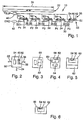
Die Abbildung der
Die Sensoreinheiten sind entlang einer Strecke 30 in gleichmäßigen Abständen 32 an Positionen Pn= 1...N angeordnet, wobei eine erste Sensoreinheit S1 an einem Anfang der Strecke und eine letzte Sensoreinheit SN an einem Ende der Strecke 30 angeordnet ist.The sensor units are arranged along a
Jede Sensoreinheit Sn weist einen Versorgungsspannungsanschluss 32, einen zweiten Versorgungsspannungsanschluss 34 und einen Schaltausgang 36 auf, wobei der Schaltausgang 36 einen on-Zustand und einen off-Zustand aufweist. Der Schaltausgang 36 einer jeden Sensoreinheit Sn schaltet im dargestellten Ausführungsbeispiel in Abhängigkeit von einem ersten Schwellwert aufgrund einer Schwellwertüberschreitung des Sensorsignals der Sensoreinheit Sn in den on-Zustand und aufgrund einer Unterschreitung des ersten Schwellwerts in den off-Zustand.Each sensor unit Sn has a
Ferner weist jeder Sensoreinheit Sn einen Träger 50 mit einer Oberfläche 52, einen auf der Oberfläche 52 angeordnete Messeinheit 54 sowie einen auf der Oberfläche 52 angeordneten Bias-Magneten 56 mit einem ersten Pol 60 und einem zweiten Pol 62 auf. Der Bias-Magnet 56 ist in einer von dem Anfang der Strecke zu dem Ende der Strecke 30 zeigenden ersten Richtung jeweils hinter der Messeinheit 54 der Sensoreinheit angeordnet und so ausgerichtet, dass der erste Pol 60 in der ersten Richtung vor dem zweiten Pol 62 angeordnet ist. Träger 50, Messeinheit 54 und Bias-Magnet 56 sind in
Der erste Versorgungsspannungsanschiuss 32 der ersten Sensoreinheit S1 ist an eine Versorgungsspannung Vsup angeschlossen und der zweite Versorgungsspannungsanschluss 34 der ersten Sensoreinheit S1 ist an ein Referenzpotential GND angeschlossen, so dass die erste Sensoreinheit S1 bei Inbetriebnahme der Positionsbestimmungseinheit 10 immer eingeschaltet ist und daher immer eine Stromaufnahme Isup aufweist.The first
Alle weiteren Sensoreinheiten Sn=2...N sind mittels des jeweiligen Versorgungsspannungsanschlusses 32 ebenfalls an die Versorgungsspannung Vsup angeschlossen. Der zweite Versorgungsspannungsanschluss 34 der weiteren Sensoreinheiten Sn=2...N ist jeweils mit dem Schaltausgang 36 der entlang der Strecke 30 unmittelbar vorausgehenden Sensoreinheit Sn-1 verbunden. Hierdurch werden die weiteren Sensoreinheiten Sn=2...N jeweils mittels der unmittelbar vorausgehenden Sensoreinheit Sn-1 aufgrund einer durch die unmittelbar vorausgehenden Sensoreinheit detektierten Schwellwertüberschreitung eingeschaltet. Eine solche Verschaltung wird auch als Daisy-Chain bezeichnet. In dem eingeschalteten Zustand weisen die weiteren Sensoreinheiten Sn=z...N jeweils ebenfalls eine Stromaufnahme Isup auf, wobei die jeweiligen Stromaufnahmen aller Sensoreinheiten Sn aufgrund der Gleichartigkeit der Sensoreinheiten eine geringe Varianz aufweisen.All further sensor units Sn = 2... N are likewise connected to the supply voltage Vsup by means of the respective
Zur Kostenreduzierung lässt sich die letzte Sensoreinheit SN auch als kostengünstigerer Stromverbraucher, z.B. als Widerstand mit an die Versorgungsspannungen angepasstem Widerstandswert und ohne einen dem Schaltausgang entsprechenden Anschluss ausführen.To reduce costs, the last sensor unit SN can also be used as a cheaper electricity consumer, e.g. as a resistor with a resistance value adapted to the supply voltages and without a connection corresponding to the switching output.
Der Geber 20 ist aus einem ferromagnetischen Material besteht oder ein ferromagnetisches Material umfasst und weist ein erstes Ende 22 und eine Länge 24 auf. Der Geber 20 ist parallel zu der Strecke 30 beweglich, wobei sich hierdurch auch das erste Ende 22 entlang der gesamten Strecke 30 verschiebt und die Länge 24 des Gebers 22 größer oder gleich der Länge der Strecke 30 ist.The
In dem dargestellten Ausführungsbeispiei ist die Strommesseinheit 40 in der Leitung der ersten Versorgungsspannung Vsup unmittelbar vor einem ersten Spannungsknoten des ersten Sensors S1 eingeschleift ist. Alternativ lässt sich die Strommesseinheit 40 auch in die Leitung für das Referenzpotential GND vor dem zweiten Versorgungsspannungsanschluss 34 einschleifen - gestrichelt dargestellt.In the illustrated embodiment, the
In beiden Ausführungsformen lässt sich mittels der Strommesseinheit 40 ein Summenstrom Isum auf einfache Weise bestimmen, wobei sich der Summenstrom aus den Stromaufnahmen Isup aller eingeschalteter Sensoren Sn ergibt. Der Summenstrom Isum entspricht somit einem Vielfachen m der Stromaufnahme Isup eines einzelnen Sensors Sn: ![]()
![]()
Im dargestellten Ausführungsbeispiel lässt sich aus der folgenden Gleichung anhand des messbaren Faktors F1 bestimmen, über welchem Sensoreinheit Sn sich das erste Ende 22 des Gebers 20 befindet: ![]()
![]()
Folglich befindet sich das erste Ende 22 an der Position Pm-1 des (m-1)-ten Sensoreinheites Sm-1.As a result, the
Befindet sich das erste Ende 22 des Gebers 20, wie im Ausführungsbeispiel dargestellt, über dem dritten Sensoreinheit S3, also an der Position P3 der dritten Sensoreinheit S3, so überdeckt der Geber 20 die Sensoreinheiten S1, S2 und S3. Für die Sensoreinheiten S1, S2, S3 liegt das jeweilige Sensorsignal über dem ersten Schwellwert, der jeweilige Schaltausgang ist in den on-Zustand geschaltet, so dass sich die Sensoreinheiten S1 bis S4 in dem eingeschalteten Zustand befinden. Nur Sensoreinheit S5 befindet sich noch in einem ausgeschalteten Zustand. Somit tragen die vier Sensoreinheiten zu dem Summenstrom Isum bei, der Faktor m beträgt Toigiich-vier.If the
Zur Erhöhung der Genauigkeit der Positionsbestimmung weisen die Sensoreinheiten Sn=1...N gemäß einer Weiterbildung jeweils einen zweiten Schwellwert auf, wobei der zweite Schwellwert kleiner als der erste Schwellwert ist. Bei Überschreiten des ersten Schwellwerts ist der Schaltausgang jeder Sensoreinheit in den on-Zustand geschaltet, bei Unterschreiten des zweiten Schwellwerts ist der Schaltausgang jeweils in den off-Zustand geschaltet. Für zwischen dem ersten und dem zweiten Schwellwert liegende Sensorsignale wird der Schaltausgang pulsweitenmoduliert von dem off-Zustand in den on-Zustand geschaltet. Die Pulsweitenmodulation weist einen Tastgrad auf, der Proportional zu dem Sensorsignal der jeweiligen Sensoreinheit ist.To increase the accuracy of the position determination, the sensor units Sn = 1... N according to a development each have a second threshold value, wherein the second threshold value is smaller than the first threshold value. When the first threshold value is exceeded, the switching output of each sensor unit is switched to the on state; when the second threshold value is undershot, the switching output is in each case switched to the off state. For sensor signals lying between the first and second threshold values, the switching output is switched from the off state to the on state in pulse width modulated fashion. The pulse width modulation has a duty factor which is proportional to the sensor signal of the respective sensor unit.
Die Stromaufnahme Ipwm eines pulsweitenmoduliert geschalteten Sensoreinheit Sn, also eines mit einem pulsweitenmodulierten Schaltausgang eines unmittelbar vorausgehenden Sensoreinheit Sn-1 verbundenen Sensoreinheit Sn, ist geringer als die Stromaufnahme Isup eines vollständig eingeschalteten Sensoreinheit Sn. Durch die Proportionalität des Tastgrads der Pulsweitenmodulation zu dem Sensorsignal ist auch die Stromaufnahme Ipwm des pulsweitenmoduliert geschalteten Sensoreinheit proportional zu dem Sensorsignal und damit proportional zu der Position des ersten Endes 22 des Gebers im Bereich oberhalb des vorausgehenden Sensoreinheit Sn-1. Hierdurch wird die Position Pp des ersten Endes 22 des Gebers 20 im Bereich einer einzelnen Sensoreinheit genauer aufgelöst.The current consumption Ipwm of a pulse width modulated switched sensor unit Sn, so one with a pulse width modulated switching output an immediately preceding sensor unit Sn-1 connected sensor unit Sn, is less than the current consumption Isup of a fully switched sensor unit Sn. Due to the proportionality of the duty cycle of the pulse width modulation to the sensor signal and the current Ipwm of the pulse width modulated switched sensor unit is proportional to the sensor signal and thus proportional to the position of the
Befindet sich das erste Ende 22, wie in ![]()
![]()
Folglich ist anhand des Vielfachen m der Stromaufnahme Isup, hier drei, ablesbar, über welchem Sensoreinheit Sn sich das erste Ende 22 des Gebers befindet. Indem alle möglichen Werte des Stroms Ipwm auf eine einer Breite eines Sensoreinheit entlang der Strecke oder auf eine dem Abstand zwischen zwei Sensoreinheiten entsprechenden Weg abgebildet werden und der dem gemessenen Strom Ipwm Anteil an der Breite oder dem Weg bestimmt wird, kann die Position des ersten Endes 22 des Gebers 20 im Bereich des dritten Sensoreinheit genauer bestimmt werden.Consequently, on the basis of the multiple m of the current consumption Isup, here three, can be read, above which sensor unit Sn is the
In den Abbildungen der
In den Abbildungen der
In
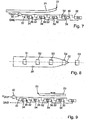
Die in den
In der Abbildung der
Der Geber 20 erstreckt sich von dem ersten Ende 22 in Richtung des letzten Sensoreinheit SN, wobei die Länge 24 des Gebers 20 nur einen Teilbereich der Strecke 30 überdeckt.The
Bei Abwesenheit des Gebers 20 befinden sich alle Sensoreinheiten Sn in dem eingeschalteten Zustand, da für jeden Sensoreinheit Sn der erste Schwellwert unterschritten ist und das Ausgangssignal 36 in den on-Zustand geschaltet ist.In the absence of the
Befindet sich das erste Ende 22 des Gebers in einem Bereich eines m-ten Sensoreinheit, z.B. wie dargestellt in dem Bereich der dritten Sensoreinheit S3, also an der Position P3, so überschreitet das Sensorsignal der dritten Sensoreinheit S3 den ersten Schwellwert und das Ausgangssignal 36 des dritten Sensoreinheit S3 ist in den off-Zustand geschaltet. Hierdurch befinden sich alle folgenden Sensoreinheiten S4, S5 in dem ausgeschalteten Zustand und weisen keine Stromaufnahme Isup auf. Zu dem Summenstrom Isum tragen nur die Stromaufnahmen Isup der entlang der Strecke vorausgehenden Sensoreinheiten S1 und S2 bei. Somit kann anhand des Faktor m aus Isum = m* Isup der Sensoreinheit Sn bzw. die Position Pn der Sensoreinheit Sn, an der sich das erste Ende 22 des Gebers 20 befindet, wie folgt bestimmt werden: ![]()
![]()
Die hinsichtlich des Ausführungsbeispiels gemäß
Claims (19)
dadurch gekennzeichnet, dass
characterized in that
Applications Claiming Priority (1)
| Application Number | Priority Date | Filing Date | Title |
|---|---|---|---|
| DE102016002488.7A DE102016002488B3 (en) | 2016-03-03 | 2016-03-03 | Position Determination Entity |
Publications (2)
| Publication Number | Publication Date |
|---|---|
| EP3214412A1 true EP3214412A1 (en) | 2017-09-06 |
| EP3214412B1 EP3214412B1 (en) | 2018-06-27 |
Family
ID=58231327
Family Applications (1)
| Application Number | Title | Priority Date | Filing Date |
|---|---|---|---|
| EP17000322.2A Active EP3214412B1 (en) | 2016-03-03 | 2017-03-02 | Positioning unit |
Country Status (3)
| Country | Link |
|---|---|
| US (1) | US10429209B2 (en) |
| EP (1) | EP3214412B1 (en) |
| DE (1) | DE102016002488B3 (en) |
Families Citing this family (3)
| Publication number | Priority date | Publication date | Assignee | Title |
|---|---|---|---|---|
| DE102016002487B3 (en) * | 2016-03-03 | 2017-08-03 | Tdk-Micronas Gmbh | Positioning sensor unit |
| US10634520B1 (en) * | 2018-05-09 | 2020-04-28 | Upc Llc | Expandable switch sensors with expandable magnetic actuators |
| DE102018008751B3 (en) | 2018-08-13 | 2019-08-08 | Pepperl+Fuchs Gmbh | circuitry |
Citations (4)
| Publication number | Priority date | Publication date | Assignee | Title |
|---|---|---|---|---|
| DE20009155U1 (en) * | 2000-05-20 | 2000-08-24 | Festo Ag & Co | Position detection device and adjusting device equipped therewith |
| US20120136541A1 (en) * | 2010-11-25 | 2012-05-31 | Denso Corporation | Communication system for a passenger protection system |
| DE112009004394B4 (en) | 2009-01-16 | 2015-12-17 | Allegro Microsystems, Llc | Determination of addresses of electrical components or components which are arranged in a daisy chain |
| WO2015192965A1 (en) | 2014-06-18 | 2015-12-23 | Caterpillar Global Mining Europe Gmbh | Sensing device for a digital linear position sensor |
Family Cites Families (10)
| Publication number | Priority date | Publication date | Assignee | Title |
|---|---|---|---|---|
| US4367506A (en) * | 1978-06-06 | 1983-01-04 | Arie Lapsker | Protective system for electric motors |
| JP3513936B2 (en) * | 1993-12-22 | 2004-03-31 | 松下電工株式会社 | Optical scanning displacement measuring device |
| US5668533A (en) * | 1995-06-07 | 1997-09-16 | Securitron Magnalock Corporation | High security balanced-type, magnetically-actuated proximity switch system |
| US7224204B2 (en) * | 2005-03-08 | 2007-05-29 | Linear Technology Corporation | Method and circuit for driving a gate of a MOS transistor negative |
| JP4232808B2 (en) * | 2006-09-19 | 2009-03-04 | 日立金属株式会社 | Magnetic encoder device |
| ATE470160T1 (en) * | 2006-10-20 | 2010-06-15 | Pepperl & Fuchs | METHOD FOR MONITORING WHETHER THE SWITCHING THRESHOLD OF A SWITCH TRANSMITTER IS WITHIN A SPECIFIED TOLERANCE RANGE |
| US8129984B2 (en) * | 2007-06-27 | 2012-03-06 | Brooks Automation, Inc. | Multiple dimension position sensor |
| US9182459B2 (en) * | 2011-09-08 | 2015-11-10 | Honeywell International Inc. | Wireless magnetic position sensor |
| WO2014042690A1 (en) * | 2012-09-13 | 2014-03-20 | Moog Inc. | Method and apparatae for controlling and providing a voltage converter with a pulse-width-modulated switch |
| US8823193B1 (en) * | 2013-05-28 | 2014-09-02 | Siemens Aktiengesellschaft | Method and system for limitation of power output variation in variable generation renewable facilities |
-
2016
- 2016-03-03 DE DE102016002488.7A patent/DE102016002488B3/en not_active Withdrawn - After Issue
-
2017
- 2017-03-02 EP EP17000322.2A patent/EP3214412B1/en active Active
- 2017-03-03 US US15/449,650 patent/US10429209B2/en active Active
Patent Citations (4)
| Publication number | Priority date | Publication date | Assignee | Title |
|---|---|---|---|---|
| DE20009155U1 (en) * | 2000-05-20 | 2000-08-24 | Festo Ag & Co | Position detection device and adjusting device equipped therewith |
| DE112009004394B4 (en) | 2009-01-16 | 2015-12-17 | Allegro Microsystems, Llc | Determination of addresses of electrical components or components which are arranged in a daisy chain |
| US20120136541A1 (en) * | 2010-11-25 | 2012-05-31 | Denso Corporation | Communication system for a passenger protection system |
| WO2015192965A1 (en) | 2014-06-18 | 2015-12-23 | Caterpillar Global Mining Europe Gmbh | Sensing device for a digital linear position sensor |
Also Published As
| Publication number | Publication date |
|---|---|
| EP3214412B1 (en) | 2018-06-27 |
| US20170254669A1 (en) | 2017-09-07 |
| US10429209B2 (en) | 2019-10-01 |
| DE102016002488B3 (en) | 2017-08-03 |
Similar Documents
| Publication | Publication Date | Title |
|---|---|---|
| DE10111949B4 (en) | Magnetic detection device | |
| DE1196410C2 (en) | Learnable distinction matrix for groups of analog signals | |
| EP3214412B1 (en) | Positioning unit | |
| DE2002203C3 (en) | Electric speedometer | |
| EP0620416B1 (en) | Magnetic measuring system | |
| DE102004057909A1 (en) | Linear position sensor | |
| DE3633791A1 (en) | PROCEDURE AND ARRANGEMENT FOR MEASURING THE RESISTANCE RATIO ON A RESISTANCE HALF-BRIDGE | |
| DE3117808A1 (en) | CIRCUIT ARRANGEMENT FOR MEASURING INDUCTIVE CHANGES | |
| EP2348326B1 (en) | Current sensor unit and method for signal and/or data transfer | |
| DE1043479B (en) | Electrical relay protection system | |
| DE2126441A1 (en) | Electronic measuring instrument with digital display device | |
| EP1816483B1 (en) | Short-circuit and overcurrent detection circuit | |
| DE1283377B (en) | Digital DC voltmeter | |
| EP3214411B1 (en) | Position determining sensor unit | |
| DE2341322A1 (en) | ARRANGEMENT FOR GENERATING A MEASUREMENT OUTPUT SIGNAL, THE LEVEL OF THE LINEAR DEPENDING ON THE SIZE OF A RESISTANCE TO BE MEASURED | |
| DE2300802A1 (en) | CIRCUIT ARRANGEMENT FOR POTENTIAL-FREE CURRENT MEASUREMENT | |
| EP0183919A1 (en) | Valve comprising a circuit arrangement for determination of the position of said valve | |
| EP0280261A2 (en) | Circuit for getting a temperature independent rectangular signal from a measuring signal | |
| EP2174146B1 (en) | Arrangement and method for measuring a current flowing in an electrical conductor | |
| DE4237540A1 (en) | Process for high-resolution measurement of linear and rotary positions | |
| DE10023503B4 (en) | position switch | |
| EP1352257B1 (en) | Device for sensing a magnetic field, a magnetic field meter and an ammeter | |
| DE3824267C2 (en) | ||
| DE19808929A1 (en) | Sensor arrangement | |
| WO2020119909A1 (en) | Distance-measuring device |
Legal Events
| Date | Code | Title | Description |
|---|---|---|---|
| PUAI | Public reference made under article 153(3) epc to a published international application that has entered the european phase |
Free format text: ORIGINAL CODE: 0009012 |
|
| STAA | Information on the status of an ep patent application or granted ep patent |
Free format text: STATUS: THE APPLICATION HAS BEEN PUBLISHED |
|
| AK | Designated contracting states |
Kind code of ref document: A1 Designated state(s): AL AT BE BG CH CY CZ DE DK EE ES FI FR GB GR HR HU IE IS IT LI LT LU LV MC MK MT NL NO PL PT RO RS SE SI SK SM TR |
|
| AX | Request for extension of the european patent |
Extension state: BA ME |
|
| STAA | Information on the status of an ep patent application or granted ep patent |
Free format text: STATUS: REQUEST FOR EXAMINATION WAS MADE |
|
| 17P | Request for examination filed |
Effective date: 20171005 |
|
| RBV | Designated contracting states (corrected) |
Designated state(s): AL AT BE BG CH CY CZ DE DK EE ES FI FR GB GR HR HU IE IS IT LI LT LU LV MC MK MT NL NO PL PT RO RS SE SI SK SM TR |
|
| GRAP | Despatch of communication of intention to grant a patent |
Free format text: ORIGINAL CODE: EPIDOSNIGR1 |
|
| STAA | Information on the status of an ep patent application or granted ep patent |
Free format text: STATUS: GRANT OF PATENT IS INTENDED |
|
| RIC1 | Information provided on ipc code assigned before grant |
Ipc: G01D 5/251 20060101AFI20180202BHEP |
|
| INTG | Intention to grant announced |
Effective date: 20180312 |
|
| GRAS | Grant fee paid |
Free format text: ORIGINAL CODE: EPIDOSNIGR3 |
|
| GRAA | (expected) grant |
Free format text: ORIGINAL CODE: 0009210 |
|
| STAA | Information on the status of an ep patent application or granted ep patent |
Free format text: STATUS: THE PATENT HAS BEEN GRANTED |
|
| AK | Designated contracting states |
Kind code of ref document: B1 Designated state(s): AL AT BE BG CH CY CZ DE DK EE ES FI FR GB GR HR HU IE IS IT LI LT LU LV MC MK MT NL NO PL PT RO RS SE SI SK SM TR |
|
| REG | Reference to a national code |
Ref country code: GB Ref legal event code: FG4D Free format text: NOT ENGLISH |
|
| REG | Reference to a national code |
Ref country code: AT Ref legal event code: REF Ref document number: 1012728 Country of ref document: AT Kind code of ref document: T Effective date: 20180715 |
|
| REG | Reference to a national code |
Ref country code: DE Ref legal event code: R096 Ref document number: 502017000057 Country of ref document: DE |
|
| REG | Reference to a national code |
Ref country code: IE Ref legal event code: FG4D Free format text: LANGUAGE OF EP DOCUMENT: GERMAN |
|
| PG25 | Lapsed in a contracting state [announced via postgrant information from national office to epo] |
Ref country code: LT Free format text: LAPSE BECAUSE OF FAILURE TO SUBMIT A TRANSLATION OF THE DESCRIPTION OR TO PAY THE FEE WITHIN THE PRESCRIBED TIME-LIMIT Effective date: 20180627 Ref country code: NO Free format text: LAPSE BECAUSE OF FAILURE TO SUBMIT A TRANSLATION OF THE DESCRIPTION OR TO PAY THE FEE WITHIN THE PRESCRIBED TIME-LIMIT Effective date: 20180927 Ref country code: FI Free format text: LAPSE BECAUSE OF FAILURE TO SUBMIT A TRANSLATION OF THE DESCRIPTION OR TO PAY THE FEE WITHIN THE PRESCRIBED TIME-LIMIT Effective date: 20180627 Ref country code: BG Free format text: LAPSE BECAUSE OF FAILURE TO SUBMIT A TRANSLATION OF THE DESCRIPTION OR TO PAY THE FEE WITHIN THE PRESCRIBED TIME-LIMIT Effective date: 20180927 Ref country code: SE Free format text: LAPSE BECAUSE OF FAILURE TO SUBMIT A TRANSLATION OF THE DESCRIPTION OR TO PAY THE FEE WITHIN THE PRESCRIBED TIME-LIMIT Effective date: 20180627 |
|
| REG | Reference to a national code |
Ref country code: NL Ref legal event code: MP Effective date: 20180627 |
|
| REG | Reference to a national code |
Ref country code: LT Ref legal event code: MG4D |
|
| PG25 | Lapsed in a contracting state [announced via postgrant information from national office to epo] |
Ref country code: RS Free format text: LAPSE BECAUSE OF FAILURE TO SUBMIT A TRANSLATION OF THE DESCRIPTION OR TO PAY THE FEE WITHIN THE PRESCRIBED TIME-LIMIT Effective date: 20180627 Ref country code: GR Free format text: LAPSE BECAUSE OF FAILURE TO SUBMIT A TRANSLATION OF THE DESCRIPTION OR TO PAY THE FEE WITHIN THE PRESCRIBED TIME-LIMIT Effective date: 20180928 Ref country code: HR Free format text: LAPSE BECAUSE OF FAILURE TO SUBMIT A TRANSLATION OF THE DESCRIPTION OR TO PAY THE FEE WITHIN THE PRESCRIBED TIME-LIMIT Effective date: 20180627 Ref country code: LV Free format text: LAPSE BECAUSE OF FAILURE TO SUBMIT A TRANSLATION OF THE DESCRIPTION OR TO PAY THE FEE WITHIN THE PRESCRIBED TIME-LIMIT Effective date: 20180627 |
|
| PG25 | Lapsed in a contracting state [announced via postgrant information from national office to epo] |
Ref country code: NL Free format text: LAPSE BECAUSE OF FAILURE TO SUBMIT A TRANSLATION OF THE DESCRIPTION OR TO PAY THE FEE WITHIN THE PRESCRIBED TIME-LIMIT Effective date: 20180627 |
|
| PG25 | Lapsed in a contracting state [announced via postgrant information from national office to epo] |
Ref country code: PL Free format text: LAPSE BECAUSE OF FAILURE TO SUBMIT A TRANSLATION OF THE DESCRIPTION OR TO PAY THE FEE WITHIN THE PRESCRIBED TIME-LIMIT Effective date: 20180627 Ref country code: SK Free format text: LAPSE BECAUSE OF FAILURE TO SUBMIT A TRANSLATION OF THE DESCRIPTION OR TO PAY THE FEE WITHIN THE PRESCRIBED TIME-LIMIT Effective date: 20180627 Ref country code: RO Free format text: LAPSE BECAUSE OF FAILURE TO SUBMIT A TRANSLATION OF THE DESCRIPTION OR TO PAY THE FEE WITHIN THE PRESCRIBED TIME-LIMIT Effective date: 20180627 Ref country code: CZ Free format text: LAPSE BECAUSE OF FAILURE TO SUBMIT A TRANSLATION OF THE DESCRIPTION OR TO PAY THE FEE WITHIN THE PRESCRIBED TIME-LIMIT Effective date: 20180627 Ref country code: IS Free format text: LAPSE BECAUSE OF FAILURE TO SUBMIT A TRANSLATION OF THE DESCRIPTION OR TO PAY THE FEE WITHIN THE PRESCRIBED TIME-LIMIT Effective date: 20181027 Ref country code: EE Free format text: LAPSE BECAUSE OF FAILURE TO SUBMIT A TRANSLATION OF THE DESCRIPTION OR TO PAY THE FEE WITHIN THE PRESCRIBED TIME-LIMIT Effective date: 20180627 |
|
| PG25 | Lapsed in a contracting state [announced via postgrant information from national office to epo] |
Ref country code: ES Free format text: LAPSE BECAUSE OF FAILURE TO SUBMIT A TRANSLATION OF THE DESCRIPTION OR TO PAY THE FEE WITHIN THE PRESCRIBED TIME-LIMIT Effective date: 20180627 Ref country code: SM Free format text: LAPSE BECAUSE OF FAILURE TO SUBMIT A TRANSLATION OF THE DESCRIPTION OR TO PAY THE FEE WITHIN THE PRESCRIBED TIME-LIMIT Effective date: 20180627 Ref country code: IT Free format text: LAPSE BECAUSE OF FAILURE TO SUBMIT A TRANSLATION OF THE DESCRIPTION OR TO PAY THE FEE WITHIN THE PRESCRIBED TIME-LIMIT Effective date: 20180627 |
|
| REG | Reference to a national code |
Ref country code: DE Ref legal event code: R097 Ref document number: 502017000057 Country of ref document: DE |
|
| PLBE | No opposition filed within time limit |
Free format text: ORIGINAL CODE: 0009261 |
|
| STAA | Information on the status of an ep patent application or granted ep patent |
Free format text: STATUS: NO OPPOSITION FILED WITHIN TIME LIMIT |
|
| PG25 | Lapsed in a contracting state [announced via postgrant information from national office to epo] |
Ref country code: DK Free format text: LAPSE BECAUSE OF FAILURE TO SUBMIT A TRANSLATION OF THE DESCRIPTION OR TO PAY THE FEE WITHIN THE PRESCRIBED TIME-LIMIT Effective date: 20180627 |
|
| 26N | No opposition filed |
Effective date: 20190328 |
|
| PG25 | Lapsed in a contracting state [announced via postgrant information from national office to epo] |
Ref country code: SI Free format text: LAPSE BECAUSE OF FAILURE TO SUBMIT A TRANSLATION OF THE DESCRIPTION OR TO PAY THE FEE WITHIN THE PRESCRIBED TIME-LIMIT Effective date: 20180627 |
|
| PG25 | Lapsed in a contracting state [announced via postgrant information from national office to epo] |
Ref country code: MC Free format text: LAPSE BECAUSE OF FAILURE TO SUBMIT A TRANSLATION OF THE DESCRIPTION OR TO PAY THE FEE WITHIN THE PRESCRIBED TIME-LIMIT Effective date: 20180627 |
|
| PG25 | Lapsed in a contracting state [announced via postgrant information from national office to epo] |
Ref country code: LU Free format text: LAPSE BECAUSE OF NON-PAYMENT OF DUE FEES Effective date: 20190302 Ref country code: AL Free format text: LAPSE BECAUSE OF FAILURE TO SUBMIT A TRANSLATION OF THE DESCRIPTION OR TO PAY THE FEE WITHIN THE PRESCRIBED TIME-LIMIT Effective date: 20180627 |
|
| REG | Reference to a national code |
Ref country code: BE Ref legal event code: MM Effective date: 20190331 |
|
| PG25 | Lapsed in a contracting state [announced via postgrant information from national office to epo] |
Ref country code: IE Free format text: LAPSE BECAUSE OF NON-PAYMENT OF DUE FEES Effective date: 20190302 |
|
| PG25 | Lapsed in a contracting state [announced via postgrant information from national office to epo] |
Ref country code: BE Free format text: LAPSE BECAUSE OF NON-PAYMENT OF DUE FEES Effective date: 20190331 |
|
| PG25 | Lapsed in a contracting state [announced via postgrant information from national office to epo] |
Ref country code: TR Free format text: LAPSE BECAUSE OF FAILURE TO SUBMIT A TRANSLATION OF THE DESCRIPTION OR TO PAY THE FEE WITHIN THE PRESCRIBED TIME-LIMIT Effective date: 20180627 |
|
| PG25 | Lapsed in a contracting state [announced via postgrant information from national office to epo] |
Ref country code: MT Free format text: LAPSE BECAUSE OF FAILURE TO SUBMIT A TRANSLATION OF THE DESCRIPTION OR TO PAY THE FEE WITHIN THE PRESCRIBED TIME-LIMIT Effective date: 20180627 Ref country code: PT Free format text: LAPSE BECAUSE OF FAILURE TO SUBMIT A TRANSLATION OF THE DESCRIPTION OR TO PAY THE FEE WITHIN THE PRESCRIBED TIME-LIMIT Effective date: 20181029 |
|
| REG | Reference to a national code |
Ref country code: CH Ref legal event code: PL |
|
| PG25 | Lapsed in a contracting state [announced via postgrant information from national office to epo] |
Ref country code: LI Free format text: LAPSE BECAUSE OF NON-PAYMENT OF DUE FEES Effective date: 20200331 Ref country code: CH Free format text: LAPSE BECAUSE OF NON-PAYMENT OF DUE FEES Effective date: 20200331 |
|
| PGFP | Annual fee paid to national office [announced via postgrant information from national office to epo] |
Ref country code: FR Payment date: 20210324 Year of fee payment: 5 |
|
| PG25 | Lapsed in a contracting state [announced via postgrant information from national office to epo] |
Ref country code: CY Free format text: LAPSE BECAUSE OF FAILURE TO SUBMIT A TRANSLATION OF THE DESCRIPTION OR TO PAY THE FEE WITHIN THE PRESCRIBED TIME-LIMIT Effective date: 20180627 |
|
| PGFP | Annual fee paid to national office [announced via postgrant information from national office to epo] |
Ref country code: GB Payment date: 20210324 Year of fee payment: 5 |
|
| PG25 | Lapsed in a contracting state [announced via postgrant information from national office to epo] |
Ref country code: HU Free format text: LAPSE BECAUSE OF FAILURE TO SUBMIT A TRANSLATION OF THE DESCRIPTION OR TO PAY THE FEE WITHIN THE PRESCRIBED TIME-LIMIT; INVALID AB INITIO Effective date: 20170302 |
|
| PG25 | Lapsed in a contracting state [announced via postgrant information from national office to epo] |
Ref country code: MK Free format text: LAPSE BECAUSE OF FAILURE TO SUBMIT A TRANSLATION OF THE DESCRIPTION OR TO PAY THE FEE WITHIN THE PRESCRIBED TIME-LIMIT Effective date: 20180627 |
|
| GBPC | Gb: european patent ceased through non-payment of renewal fee |
Effective date: 20220302 |
|
| PG25 | Lapsed in a contracting state [announced via postgrant information from national office to epo] |
Ref country code: GB Free format text: LAPSE BECAUSE OF NON-PAYMENT OF DUE FEES Effective date: 20220302 Ref country code: FR Free format text: LAPSE BECAUSE OF NON-PAYMENT OF DUE FEES Effective date: 20220331 |
|
| REG | Reference to a national code |
Ref country code: AT Ref legal event code: MM01 Ref document number: 1012728 Country of ref document: AT Kind code of ref document: T Effective date: 20220302 |
|
| PGFP | Annual fee paid to national office [announced via postgrant information from national office to epo] |
Ref country code: DE Payment date: 20220620 Year of fee payment: 7 |
|
| PG25 | Lapsed in a contracting state [announced via postgrant information from national office to epo] |
Ref country code: AT Free format text: LAPSE BECAUSE OF NON-PAYMENT OF DUE FEES Effective date: 20220302 |
|
| PGFP | Annual fee paid to national office [announced via postgrant information from national office to epo] |
Ref country code: DE Payment date: 20240320 Year of fee payment: 8 |