EP3214349A1 - Dust seal - Google Patents
Dust seal Download PDFInfo
- Publication number
- EP3214349A1 EP3214349A1 EP15859612.2A EP15859612A EP3214349A1 EP 3214349 A1 EP3214349 A1 EP 3214349A1 EP 15859612 A EP15859612 A EP 15859612A EP 3214349 A1 EP3214349 A1 EP 3214349A1
- Authority
- EP
- European Patent Office
- Prior art keywords
- bushing
- bellows
- dust seal
- axis
- end portion
- Prior art date
- Legal status (The legal status is an assumption and is not a legal conclusion. Google has not performed a legal analysis and makes no representation as to the accuracy of the status listed.)
- Granted
Links
- 239000000428 dust Substances 0.000 title claims abstract description 158
- 238000004073 vulcanization Methods 0.000 claims abstract description 45
- 230000002093 peripheral effect Effects 0.000 claims description 85
- 238000007789 sealing Methods 0.000 claims description 21
- 230000000994 depressogenic effect Effects 0.000 claims description 10
- 239000013013 elastic material Substances 0.000 claims description 8
- 229920001971 elastomer Polymers 0.000 abstract description 23
- 239000005060 rubber Substances 0.000 abstract description 23
- 238000000034 method Methods 0.000 abstract description 15
- 238000000465 moulding Methods 0.000 description 24
- 239000000463 material Substances 0.000 description 19
- 230000003014 reinforcing effect Effects 0.000 description 17
- 230000014759 maintenance of location Effects 0.000 description 11
- 241000283216 Phocidae Species 0.000 description 10
- 230000008602 contraction Effects 0.000 description 10
- 230000004048 modification Effects 0.000 description 9
- 238000012986 modification Methods 0.000 description 9
- 229910052751 metal Inorganic materials 0.000 description 8
- 239000002184 metal Substances 0.000 description 8
- 229920000459 Nitrile rubber Polymers 0.000 description 6
- 239000000314 lubricant Substances 0.000 description 6
- 230000000694 effects Effects 0.000 description 5
- 239000002783 friction material Substances 0.000 description 5
- XLYOFNOQVPJJNP-UHFFFAOYSA-N water Substances O XLYOFNOQVPJJNP-UHFFFAOYSA-N 0.000 description 4
- 230000007423 decrease Effects 0.000 description 3
- 230000003247 decreasing effect Effects 0.000 description 3
- 238000004519 manufacturing process Methods 0.000 description 3
- -1 polytetrafluoroethylene Polymers 0.000 description 3
- 239000011347 resin Substances 0.000 description 3
- 229920005989 resin Polymers 0.000 description 3
- 229920000181 Ethylene propylene rubber Polymers 0.000 description 2
- CBENFWSGALASAD-UHFFFAOYSA-N Ozone Chemical compound [O-][O+]=O CBENFWSGALASAD-UHFFFAOYSA-N 0.000 description 2
- 229920000800 acrylic rubber Polymers 0.000 description 2
- 239000010960 cold rolled steel Substances 0.000 description 2
- 229920001973 fluoroelastomer Polymers 0.000 description 2
- 239000007769 metal material Substances 0.000 description 2
- 150000002739 metals Chemical class 0.000 description 2
- 229920000058 polyacrylate Polymers 0.000 description 2
- 239000010935 stainless steel Substances 0.000 description 2
- 229910001220 stainless steel Inorganic materials 0.000 description 2
- 229920003051 synthetic elastomer Polymers 0.000 description 2
- 239000005061 synthetic rubber Substances 0.000 description 2
- 229910000831 Steel Inorganic materials 0.000 description 1
- 229910052782 aluminium Inorganic materials 0.000 description 1
- XAGFODPZIPBFFR-UHFFFAOYSA-N aluminium Chemical compound [Al] XAGFODPZIPBFFR-UHFFFAOYSA-N 0.000 description 1
- 238000004891 communication Methods 0.000 description 1
- 239000004519 grease Substances 0.000 description 1
- 238000009413 insulation Methods 0.000 description 1
- 229920006122 polyamide resin Polymers 0.000 description 1
- 229920001343 polytetrafluoroethylene Polymers 0.000 description 1
- 239000004810 polytetrafluoroethylene Substances 0.000 description 1
- 230000002265 prevention Effects 0.000 description 1
- 230000002787 reinforcement Effects 0.000 description 1
- 230000000452 restraining effect Effects 0.000 description 1
- 239000010959 steel Substances 0.000 description 1
Images


Classifications
-
- F—MECHANICAL ENGINEERING; LIGHTING; HEATING; WEAPONS; BLASTING
- F16—ENGINEERING ELEMENTS AND UNITS; GENERAL MEASURES FOR PRODUCING AND MAINTAINING EFFECTIVE FUNCTIONING OF MACHINES OR INSTALLATIONS; THERMAL INSULATION IN GENERAL
- F16J—PISTONS; CYLINDERS; SEALINGS
- F16J15/00—Sealings
- F16J15/50—Sealings between relatively-movable members, by means of a sealing without relatively-moving surfaces, e.g. fluid-tight sealings for transmitting motion through a wall
- F16J15/52—Sealings between relatively-movable members, by means of a sealing without relatively-moving surfaces, e.g. fluid-tight sealings for transmitting motion through a wall by means of sealing bellows or diaphragms
-
- F—MECHANICAL ENGINEERING; LIGHTING; HEATING; WEAPONS; BLASTING
- F16—ENGINEERING ELEMENTS AND UNITS; GENERAL MEASURES FOR PRODUCING AND MAINTAINING EFFECTIVE FUNCTIONING OF MACHINES OR INSTALLATIONS; THERMAL INSULATION IN GENERAL
- F16J—PISTONS; CYLINDERS; SEALINGS
- F16J15/00—Sealings
- F16J15/16—Sealings between relatively-moving surfaces
- F16J15/32—Sealings between relatively-moving surfaces with elastic sealings, e.g. O-rings
- F16J15/3204—Sealings between relatively-moving surfaces with elastic sealings, e.g. O-rings with at least one lip
-
- F—MECHANICAL ENGINEERING; LIGHTING; HEATING; WEAPONS; BLASTING
- F16—ENGINEERING ELEMENTS AND UNITS; GENERAL MEASURES FOR PRODUCING AND MAINTAINING EFFECTIVE FUNCTIONING OF MACHINES OR INSTALLATIONS; THERMAL INSULATION IN GENERAL
- F16J—PISTONS; CYLINDERS; SEALINGS
- F16J15/00—Sealings
- F16J15/16—Sealings between relatively-moving surfaces
- F16J15/32—Sealings between relatively-moving surfaces with elastic sealings, e.g. O-rings
- F16J15/3204—Sealings between relatively-moving surfaces with elastic sealings, e.g. O-rings with at least one lip
- F16J15/3224—Sealings between relatively-moving surfaces with elastic sealings, e.g. O-rings with at least one lip capable of accommodating changes in distances or misalignment between the surfaces, e.g. able to compensate for defaults of eccentricity or angular deviations
-
- F—MECHANICAL ENGINEERING; LIGHTING; HEATING; WEAPONS; BLASTING
- F16—ENGINEERING ELEMENTS AND UNITS; GENERAL MEASURES FOR PRODUCING AND MAINTAINING EFFECTIVE FUNCTIONING OF MACHINES OR INSTALLATIONS; THERMAL INSULATION IN GENERAL
- F16J—PISTONS; CYLINDERS; SEALINGS
- F16J15/00—Sealings
- F16J15/54—Other sealings for rotating shafts
-
- F—MECHANICAL ENGINEERING; LIGHTING; HEATING; WEAPONS; BLASTING
- F16—ENGINEERING ELEMENTS AND UNITS; GENERAL MEASURES FOR PRODUCING AND MAINTAINING EFFECTIVE FUNCTIONING OF MACHINES OR INSTALLATIONS; THERMAL INSULATION IN GENERAL
- F16J—PISTONS; CYLINDERS; SEALINGS
- F16J3/00—Diaphragms; Bellows; Bellows pistons
- F16J3/04—Bellows
-
- B—PERFORMING OPERATIONS; TRANSPORTING
- B62—LAND VEHICLES FOR TRAVELLING OTHERWISE THAN ON RAILS
- B62D—MOTOR VEHICLES; TRAILERS
- B62D1/00—Steering controls, i.e. means for initiating a change of direction of the vehicle
- B62D1/02—Steering controls, i.e. means for initiating a change of direction of the vehicle vehicle-mounted
- B62D1/16—Steering columns
Definitions
- the present invention relates to a dust seal for preventing entry of foreign matter such as dust, rain, or the like, and particularly relates to a steering dust seal for a steering shaft of a steering device for a car or other vehicles.
- a steering shaft is inserted through a column hole opened in the dash panel separating the vehicle interior and the engine room.
- a gap between the steering shaft and the column hole is sealed with a steering dust seal.
- the steering dust seal prevents entry of foreign matter such as dust, rain, or the like to the vehicle interior.
- the dust seal body 102 includes a first bellows (accordion unit) 105 and a second bellows 106, which project toward the engine room, and a cylindrical attaching portion 107 joined to the end portions of the first and second bellows 105 and 106 on the outer periphery side.
- a cylindrical metal reinforcing ring 108 which serves as a reinforcement conforming to the shape of the attaching portion 107, is embedded in the attaching portion 107.
- An inner end portion 105a of the first bellows 105 and an inner end portion 106a of the second bellows 106 are fitted in the outer periphery of an end portion 101a of the bushing 101 adjacent to the vehicle interior.
- the attaching member 104 is an annular metal member that has a cross section in a generally L shape fitted in the inner end portion 105a on the inner side so as to cover the inner end portion 105a of the first bellows 105. Since the attaching member 104 is fitted in the inner end portion 105a of the first bellows 105 in this manner, the inner end portion 105a of the first bellows 105 is locked in a direction toward the vehicle interior side and pushed toward the inner periphery side, therefore, the first bellows 105 is fixed to the end portion 101a of the bushing 101 adjacent to the vehicle interior, at the inner end portion 105a. In addition, as shown in Fig.
- the inner end portion 106a of the second bellows 106 is locked in a direction toward the vehicle interior by the inner end portion 105a of the first bellows 105 fixed as described above, pushed toward the inner periphery side, and fixed to the end portion 101a of the bushing 101 adjacent to the vehicle interior.
- the seal lip 103 which is a rubber annular member, is disposed at the end portion 101b of the bushing 101 adjacent to the engine room and is slidably in contact with a surface of the steering shaft 130.
- the seal lip 103 prevents entry of foreign matter such as rain, dust or the like to a space between the steering shaft 130 and the bushing 101, and leakage of a lubricant on the inner periphery of the bushing 101.
- the attaching portion 107 of the dust seal body 102 is closely fitted in a column hole 132 of a dash panel 131 for fixation to the column hole 132 of the dash panel 131. Hence, entry of foreign matter such as rain, dust or the like in the gap between the dust seal 100 and the column hole 132 is prevented (for example, see Patent Literature 1).
- the bushing 101 is movable with the first and second bellows 105 and 106 relatively to the dash panel 131 (the column hole 132).
- the steering shaft 130 is tilted or displaced and moves relatively to the column hole 132 due to adjustment of the handle level or vibrations occurring while the car is running.
- the bushing 101 movable relatively to the column hole 132 can follow the movement of the steering shaft 130. This maintains the position of the seal lip 103 and thus works for ensuring prevention of entry of foreign matter such as rain, dust, or the like from the engine room to the vehicle interior.
- Patent Literature 1 Japanese Patent No. 4987300
- the bushing 101 is separated from the first bellows 105 and the second bellows 106, resulting in a large number of components and a complex assembly process of the conventional dust seal 100.
- the first bellows 105 and the second bellows 106 are attached to the bushing 101 by fitting the attaching member 104, so that adequate attaching strength is not provided and the deviation or vibration of the steering shaft 130 may unlock the mounting member 104 and remove the fixation between each of the first bellows 105 and the second bellows 106 and the bushing 101.
- a dust seal of the present invention is a dust seal for sealing a gap between an opening in a receiving member and a shaft inserted through the opening, including: a dust seal body in an annular shape centered about an axis; a bushing in an annular shape centered about the axis, through which the shaft is slidably inserted; and a seal lip in an annular shape centered about the axis, provided at one end of the bushing in a direction of the axis, and slidably contacting an outer peripheral surface of the shaft, characterized in that the dust seal body including: an attaching portion that is fitted into the opening of the receiving portion, is in an annular shape centered about the axis, and is made of an elastic material, a first accordion unit that has an accordion made of an elastic material and is an annular shape centered about the axis, and a second accordion unit that has an accordion made of an elastic material and is an annular shape centered about the axis, the
- the second accordion unit is integral with the attaching portion and joined to the inner peripheral surface of the attaching portion at the outer periphery.
- the second accordion unit is fitted into the inner peripheral surface of the attaching portion at the outer periphery and to thereby be fixed to the attaching portion.
- the bushing includes a first engaging part extending in an annular shape along the outer peripheral surface
- the second accordion unit includes an annular second engaging part at an end portion on the inner periphery, and the second accordion unit is locked to the outer peripheral surface of the bushing with the first engaging part and the second engaging part engaged with each other.
- the first engaging part includes a depression that extends in an annular shape along the outer peripheral surface of the bushing and that is depressed in the direction of the axis or toward the axis
- the second engaging part includes a projection that extends in an annular shape at an end portion on the inner periphery of the second accordion unit and that projects in the direction of the axis, the projection of the second engaging part is accommodated in and engaged with the depression of the first engaging part, and the second accordion unit is locked to the outer peripheral surface of the bushing.
- the bushing includes, at an end portion on a second accordion unit side in the direction of the axis, a tapered portion with a taper surface spreading from the end portion side toward an end portion side opposite to the end portion side.
- a dust seal according to the present invention can be made with a simple assembly process and exhibits high joint strength between the bushing and each accordion unit.
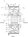
- Fig. 1 is a cross-sectional view along an axis, showing a schematic structure of a dust seal according to a first embodiment of the present invention.
- a dust seal 1 As shown in Fig. 1 , a dust seal 1 according to the first embodiment of the present invention has an annular shape centered about an axis x and includes a bushing 10, a dust seal body 20, and a seal lip 30.
- the direction indicated by the arrow a in the direction of the axis x is referred to as the outer side or the engine room side
- the direction indicated by the arrow b in the direction of the axis x is referred to as the inner side or the vehicle interior side.
- the direction (indicated by the arrow c) getting closer to the axis x in the direction vertical to the axis x (hereinafter also referred to as the radial direction) is referred to as the inner periphery side
- the direction (indicated by the arrow d) getting further away from the axis x in the vertical direction to the axis x is referred to as the outer periphery side.
- the bushing 10 has an annular shape, specifically a cylindrical shape, having the axis x at its center and is made of a low-friction material. Since a shaft is slidably inserted through the bushing 10 in a usage state as described later, the bushing 10 has an inner diameter corresponding to the outer diameter of the shaft inserted therethrough.
- the projection 12 extends on throughout the outer peripheral surface of the end portion 11, forming a flange on the end portion 11.
- the projection 12 functions as an engaging part as described later.
- a plurality of projections may be arranged at intervals in the circumferential direction in the form of an arc on a part of the periphery.
- the projections 12 may be positioned more on the inner side than the end portion 11 in the direction of the axis x at a predetermined interval.
- the bushing 10 also includes a tapered portion 14 at an end portion 13 which is the end portion on the inner side and opposite the end portion 11.
- the tapered portion 14 includes a taper surface 15 which is a circular conical surface formed on the inner peripheral surface of the end portion 13 and having a diameter decreasing toward the outer side in the direction of the axis x; and a taper surface 16 which is a circular conical surface formed on the outer peripheral surface of the end portion 13 and having a diameter increasing toward the outer side in the direction of the axis x.
- the end portion 13 projects to the outer periphery side further than an outer peripheral surface 10a between the end portions 11 and 13 of the bushing 10, and is thicker than the portion between the end portions 11 and 13 of the bushing 10.
- the bushing 10 includes an engaging part 17 at the edge of the end portion 13 on the outer periphery side and the outer side.
- the engaging part 17 includes an annular projection 17a projecting toward the outer side.
- the projection 17a faces the outer peripheral surface 10a of the bushing 10 in the radial direction, forms an annular depression 17b depressed toward the inner side in the direction of the axis x between the projection 17a and the outer peripheral surface 10a of the bushing 10.
- a lubricant such as a grease or the like is applied to the inner peripheral surface 10b of the bushing 10 on which a shaft (not shown in the drawing) slides.
- a plurality of trenches 18, extending in the direction of the axis x, is disposed at equal angular intervals in the circumferential direction.
- the trenches 18 should not necessarily be in the form of straight lines and may be in the helical, wave, or ring form, for example. Alternatively, a single trench 18 may be formed.
- the trenches 18 hold the lubricant on the inner peripheral surface 10b of the bushing 10 to allow the shaft to be smoothly slidable for a long period of time. Note that the bushing 10 should not necessarily include the trenches 18.
- the bushing 10 is made of a low-friction material as described above.
- the low-friction material include hard resin materials and metal materials.
- the resin materials include polyamide resins, polytetrafluoroethylene resins and the like.
- the metal materials include aluminum and the like.
- the dust seal body 20 includes an attaching portion 21, a first bellows (first accordion unit) 22, and a second bellows (second accordion unit) 23.
- the attaching portion 21 has an annular shape centered about the axis x, specifically a cylindrical shape, and is fitted in the opening in a receiving member as described later.
- the first bellows 22 has an annular shape centered about the axis x and is specifically a generally circular hollow disc shape and has portions depressed and projecting in the direction of the axis x.
- the second bellows 23 has an annular shape centered about the axis x and is specifically a generally circular hollow disc shape and has portions depressed and projecting in the direction of the axis x.
- the first bellows 22 and the second bellows 23 are arranged side by side in the direction of the axis x, and the first bellows 22 is disposed further on the outer side than the second bellows 23.
- the first and second bellows 22 and 23 make the bushing 10 movable and their side-by-side arrangement gives sound insulation effects.
- the attaching portion 21, the first bellows 22, and the second bellows 23 are integrally formed from the same elastic material, e.g. rubber.
- the dust seal body 20 includes a metal reinforcing ring 24 in an annular shape centered about the axis x.
- the attaching portion 21 has a flange 21a at the end portion of the attaching portion 21 on the inner side, and an outer peripheral surface 21c, which is the surface on the outer periphery side, exposed at an end portion 21b which is the end portion on the outer side.
- the reinforcing ring 24 is made of a metal, for example, stainless steel, steel SPCC(cold rolled steel sheet), or other metals, has a shape corresponding to the attaching portion 21, and is attached to the outer periphery side of the attaching portion 21.
- the reinforcing ring 24 may be at least partly embedded in the attaching portion 21.
- the reinforcing ring 24 is embedded in the outer periphery side of the attaching portion 21 such that its end portion on the outer side is embedded in and covered with the outside end portion 21b of the attaching portion 21, and the surface of its other portion on the outer periphery side is exposed.
- the first bellows 22 has concave and convex portions in the direction of the axis x and these concave and convex portions extend in a ring shape centered about the axis x, thereby forming an accordion elastic in the direction of the axis x and the radial direction.
- the first bellows 22 includes, in sequence from the inner periphery side, an annular convex portion 22a, which is convex toward the inner side, an annular concave portion 22b, which joins to the convex portion 22a on the outer periphery side and is concave toward the outer side, and an annular convex portion 22c, which joins to the concave portion 22b on the outer periphery side and is convex toward the inner side.
- These convex portions 22a and 22c and the concave portion 22b form the accordion.
- the first bellows 22 joins to an inner peripheral surface 21d, which is the inner peripheral surface of the attaching portion 21, at its end portion on the outer periphery side, i.e. at an end portion 22d, which is the end portion of the convex portion 22c on the outer periphery side.
- the first bellows 22 has an engaging part 25 at its end portion on the inner periphery side, i.e. at an end portion 22e, which is the end portion of the convex portion 22a on the inner periphery side.
- the engaging part 25 is an annular member having a generally U-shaped cross-section along the axis x (hereinafter simply referred to as cross-section) opened toward the inner periphery side.
- the engaging part 25 includes an annular depression 25a depressed toward the outer periphery side. The depression 25a can accommodate the projection 12 of the bushing 10.
- the projection 12 is accommodated in the depression 25a, the depression 25a is engaged with the projection 12, and the engaging part 25 is locked to the projection 12. Moreover, the engaging part 25 is bonded to the projection 12 by vulcanization.
- the dust seal body 20 is molded by vulcanization as described later. In the step of molding by vulcanization, the bushing 10 is placed in a mold, the first bellows 22 is molded in a state where the engaging part 25 is engaged with the projection 12 of the bushing 10 as described above, and the engaging part 25 and the projection 12 are bonded to each other by vulcanization.
- the second bellows 23 has concave and convex portions in the direction of the axis x and these concave and convex portions extend in a ring shape centered about the axis x, thereby forming an accordion elastic in the direction of the axis x and the radial direction.
- the second bellows 23 includes, in sequence from the inner periphery side, an annular convex portion 23a, which is convex toward the inner side, an annular concave portion 23b, which joins to the convex portion 23a on the outer periphery side and is concave toward the outer side, and an annular convex portion 23c, which joins to the concave portion 23b on the outer periphery side and is convex toward the inner side.
- These convex portions 23a and 23c and the concave portion 23b form the accordion.
- the second bellows 23 joins to the inner peripheral surface 21d of the attaching portion 21 at its end portion on the outer periphery side, i.e. at an end portion 23d, which is the end portion of the convex portion 23c on the outer periphery side.
- the second bellows 23 has an engaging part 26 at its end portion on the inner periphery side, i.e. at an end portion 23e, which is the end portion of the convex portion 23a on the inner periphery side.
- the engaging part 26 includes a circular disc 26a, which projects toward the inner periphery side from the end portion 23e and is a hollow circular disc in a flange form, and an annular projection 26b projecting toward the inner side from the end portion of the circular disc 26a on the inner periphery side.
- the projection 26b faces the convex portion 23a in the radial direction in the vicinity of the end portion 23e, thereby forming an annular depression 26c depressed toward the outer side between the projection 26b and the convex portion 23a.
- the engaging part 26 of the second bellows 23 is engaged with the engaging part 17 of the bushing 10, so that the second bellows 23 is locked and fixed to the bushing 10 at the engaging parts 17 and 26.
- the projection 26b of the engaging part 26 of the second bellows 23 is configured to be able to be accommodated in the depression 17b of the engaging part 17 of the bushing 10.
- the projection 17a of the engaging part 17 of the bushing 10 is configured to be able to be accommodated in the depression 26c of the engaging part 26 of the second bellows 23.
- the projection 26b is accommodated in the depression 17b.
- the projection 17a is accommodated in the depression 26c.
- the engaging part 26 is locked to the engaging part 17.
- the second bellows 23 is joined to the bushing 10.
- the second bellows 23 is configured to be able to be joined to the bushing 10 at the engaging part 26 in a simple way and in a state in which the second bellows 23 and the bushing 10 do not easily disengage.
- the end portion 13 of the bushing 10 has the tapered portion 14, and the taper surface 16 on the outer periphery side has a circular conical surface with a diameter expanding from the inner side toward the engaging part 17. Accordingly, when the bushing 10 is inserted in the second bellows 23 from the end portion 13 and then the engaging part 26 of the second bellows 23 is engaged with the engaging part 17 of the bushing 10 as described above, the engaging part 26 can slide on the taper surface 16, thereby to allow the bushing 10 to be smoothly inserted in the second bellows 23. This facilitates engagement of the engaging part 26 of the second bellows 23 with the engaging part 17 of the bushing 10.
- the first bellows 22 and the second bellows 23, in the usage state, are repeatedly expanded and contracted radially in a direction from the direction of the axis x to the radial direction such that the bushing 10 follows the movement of the shaft.
- the attaching portion 21, the first bellows 22, and the second bellows 23 fatigue resistance is required in addition to flexibility.
- ozone resistance is also required.
- the rubber material for the attaching portion 21, the first bellows 22, and the second bellows 23 is ethylene-propylene rubber, for example.
- the accordion shape (the convex portions 22a and 22c and the concave portion 22b) of the first bellows 22 should not necessarily be the above-described shape and may be any shape allowing expansion and contraction in a direction from the direction of the axis x to the radial direction.
- the shapes of the engaging part 25 of the first bellows 22 and the projection 12 of the bushing 10 should not necessarily be the above-described shapes and may be any shapes that can be engaged with each other.
- the accordion shape (the convex portions 23a and 23c and the concave portion 23b) of the second bellows 23 should not necessarily be the above-described shape and may be any shape allowing expansion and contraction in a direction from the direction of the axis x to the radial direction.
- the shapes of the engaging part 26 of the second bellows 23 and the engaging part 17 of the bushing 10 should not necessarily be the above-described shapes and may be any shapes that can be engaged with each other.
- a plurality of projections may be provided at intervals of equal angles in the circumferential direction in the form of an arc on a part of the periphery.
- the projection 17a of the bushing 10 may include a plurality of projections provided at intervals of equal angles in the circumferential direction corresponding to the plurality of projections of the second bellows 23.
- the seal lip 30 is an annular rubber component centered about the axis x, and the end portion 31, which is its end portion on the inner side, is joined to the end portion 11 of the bushing 10 at the surface of the edge portion 31on the outer side by vulcanization.
- the seal lip 30 is in a generally conical tubular shape the diameter of which decreases from the inner side toward the outer side and includes, at the end portion 32 which is the end portion on the outer side, an annular lip tip 33 with a wedge-shaped cross section projecting toward the inner periphery side. As described later, the lip tip 33 is configured to make close contact with and to be slidable on the outer peripheral surface of the shaft inserted through the bushing 10 so that the inside of the bushing 10 is sealed in the usage state.
- the seal lip 30 is made of a rubber suitable for sealing the sliding portion, different from rubbers for the attaching portion 21 and the first and second bellows 22 and 23.
- the rubber for the seal lip 30 include synthetic rubbers such as nitrile rubber (NBR), hydrogenated nitrile rubber (H-NBR), acrylic rubber (ACM), fluoro-rubber (FKM), and the like.
- the first bellows 22 and the bushing 10 are joined to each other at the projection 12 and the engaging part 25 by vulcanization bonding. This provides high bonding strength between the first bellows 22 and the bushing 10.
- the attaching portion 21, the first bellows 22, and the second bellows 23 are integrally formed from the same material. This provides high strength at the joint between the first bellows 22 and the attaching portion 21 (the end portion 22d) and the joint between the second bellows 23 and the attaching portion 21 (the end portion 23d).
- the attaching portion 21, the first bellows 22, and the second bellows 23 are separated from the seal lip 30 and therefore it is possible to choose a material having high fatigue resistance different from sealing performance required to the seal lip 30.
- the attaching portion 21, the first bellows 22, and the second bellows 23 have high strength against the above-described expansion and contraction movement, resulting in improved fatigue resistance against repeated expansion and contraction due to the movement of the bushing 10.
- the seal lip 30 is joined to the bushing 10 by vulcanization bonding, which provides high bonding strength between the seal lip 30 and the bushing 10.
- the seal lip 30 can be made of a rubber suitable for sealing a sliding portion, unlike a rubber material for the dust seal body 20, thereby improving the sealing performance of the seal lip 30. This also improves the durability of the seal lip 30.
- the attaching portion 21, the first bellows 22, and the second bellows 23 are integrally formed from the same rubber.
- the attaching portion 21, the first bellows 22, and the second bellows 23 are integrally molded by vulcanization of the same rubber.
- the bushing 10 and the reinforcing ring 24 formed into the shapes described above by a known method are placed in a mold, and then, the reinforcing ring 24 is bonded to the attaching portion 21 by vulcanization and the bushing 10 is bonded to the first bellows 22 by vulcanization.
- the reinforcing ring 24 is embedded in the attaching portion 21 and bonded thereto by vulcanization in the state where the end portion of the reinforcing ring 24 on the outer side is covered by the end portion 21b of the attaching portion 21 and the surface of the other portion of the reinforcing ring 24 on the outer periphery side is exposed.
- the engaging part 25 of the first bellows 22 is molded and bonded to the projection 12 of the bushing 10 by vulcanization in the manner in which the engaging part 25 is engaged with the projection 12.
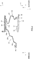
- Fig. 2 is a partial cross-sectional view showing the state before the second bellows 23 is engaged with the bushing 10. To be specific, Fig. 2 shows the state of the dust seal body 20 and the bushing 10 molded by vulcanization.
- the first bellows 22 and the attaching portion 21 are molded by vulcanization into the same shape as in the completed dust seal 1 in Fig. 1 .
- the second bellows 23 molded by vulcanization has a shape extending toward a direction away from the first bellows 22.
- the second bellows 23 is formed in such a shape that it extends diagonally from the inner peripheral surface 21d of the attaching portion 21 toward the inner periphery side and the inner side.
- the shape of the second bellows 23 after the molding by vulcanization facilitates release from the mold.
- the second bellows 23 has the completed shape with the convex portions 23a and 23c and the concave portion 23b as shown in Fig. 1 .
- the seal lip 30 is formed at the end portion 11 of the bushing 10 by the vulcanization molding.
- the molding of the seal lip 30 may be performed either concurrently with the molding of the dust seal body 20, before the molding of the dust seal body 20, or after the molding of the dust seal body 20. Since the rubber for the seal lip 30 is different from that for the attaching portion 21 and the first and second bellows 22 and 23 as described above, the molds for the dust seal body 20 and the seal lip 30 are not in communication with each other.
- the second bellows 23 in the state shown in Fig. 2 is locked to the bushing 10, so that the second bellows 23 is joined to the bushing 10, thereby completing the dust seal 1.
- the second bellows 23 is curved and the engaging part 26 is engaged with the engaging part 17 of the bushing 10, thereby forming the convex portions 23a and 23c and the concave portion 23b in the second bellows 23 as shown in Fig. 1 . Since the bushing 10 has the tapered portion 14 at the end portion 13 as described above in the step of engagement of the engaging parts 17 and 26, the engagement step is simplified.
- the first and second bellows 22 and 23, the attaching portion 21, the bushing 10, and the seal lip 30 are one component, resulting in a small number of components and a removal of a complex assembly process.
- the process for assembly of the dust seal 1 is simple.
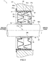
- FIG. 3 is a partial cross-sectional view showing the usage state of the dust seal 1 according to the first embodiment of the present invention.
- the dust seal 1 according to this embodiment is supposed to be used as a steering dust seal in a steering device of a vehicle, e.g. a car.
- the dust seal 1 is attached to a column hole 41 opened in a dash panel 40 separating the vehicle interior and the engine room, in order to seal the gap between a steering shaft 42, which is inserted through the column hole 41, and the column hole 41.
- the dust seal 1 prevents foreign matter such as dust, rain, or the like from entering the vehicle interior.
- the dust seal 1 is fixed to the dash panel 40 with the attaching portion 21 fitted into the column hole 41 with predetermined interference.
- the outer peripheral surface 21c of the end portion 21b of the attaching portion 21 and the outer peripheral surface 24a of the reinforcing ring 24 are in close contact with the column hole 41, thereby sealing the gap between the dash panel 40 and the dust seal 1.
- the flange 21a of the attaching portion 21 is in contact with a vehicle interior side surface 40a, which is a surface of the dash panel 40 on the vehicle interior side, so that the dust seal 1 is positioned in the direction of the axis x.
- the steering shaft 42 is inserted through the bushing 10 and the steering shaft 42 is slidably supported by the inner peripheral surface 10b of the bushing 10. Since the bushing 10 supports the steering shaft 42 with the inner peripheral surface 10b extending lengthwise in the direction of the axis x, the bushing 10 can follow the movement of the steering shaft 42 and keep a stable position with respect to the steering shaft 42 even if the steering shaft 42 is largely off-center. This can keep a proper position of the seal lip 30 contacting the steering shaft 42.
- a lubricant (not shown in the drawing) is applied to the inner peripheral surface 10b of the bushing 10, which enables smooth sliding of the steering shaft 42.
- the outer peripheral surface 42a of the steering shaft 42 is in close contact with the lip tip 33 of the seal lip 30, thereby sealing the gap between the steering shaft 42 and the bushing 10 from the engine room.
- the attaching portion 21 and the seal lip 30 seal the gap between the column hole 41 and the steering shaft 42, thereby preventing foreign matter such as dust, rain, or the like from entering the vehicle interior.
- the steering shaft 42 is tilted or displaced and moves relative to the column hole 41 due to adjustment of the handle level and vibrations occurring while the car is running. Accordingly, with the movement of the steering shaft 42, the bushing 10 moves relative to the column hole 41. With the movement of the bushing 10, the first bellows 22 and the second bellows 23 expand and contract. This expansion and contraction of the first and second bellows 22 and 23 repeatedly applies load to the joint between the first bellows 22 and the bushing 10.
- the first bellows 22 and the bushing 10 are strongly joined to each other by vulcanization bonding at the projection 12 and the engaging part 25, thereby providing high durability against load repeatedly applied to the joint between the first bellows 22 and the bushing 10 and restraining the release of the joint between the first bellows 22 and the bushing 10.
- the attaching portion 21, the first bellows 22, and the second bellows 23 are integrally formed from the same material, thereby increasing the strength at the joint (the end portion 22d) between the first bellows 22 and the attaching portion 21 and the joint (the end portion 23d) between the second bellows 23 and the attaching portion 21, therefore, it is possible to increase the durability of the dust seal 1 against the load repeatedly applied to the joints.
- the projections 26b and 17a are accommodated in and engaged with the depressions 17b and 26c, respectively, so that the second bellows 23 and the bushing 10 are joined to each other, thereby increasing the strength of the joint between the second bellows 23 and the bushing 10. This increases the durability of the dust seal 1 against the load repeatedly applied to the joint.
- the dust seal body 20 for the attaching portion 21, the first bellows 22, and the second bellows 23, a material with high fatigue resistance is selected, thereby increasing the durability of the attaching portion 21, the first bellows 22, and the second bellows 23 against load repeatedly applied to the attaching portion 21, the first bellows 22, and the second bellows 23.
- the bonding strength of the joint between each of the first and second bellows 22 and 23 and the bushing 10 and the bonding strength of the joint between each of the first and second bellows 22 and 23 and the attaching portion 21 are increased, and by the selection of the material for the dust seal body 20 the fatigue resistance is increased.
- the fatigue resistance against repeated expansion and contraction of the dust seal body 20 caused by the movement of the bushing 10 can be improved, whereby damage to the dust seal body 20 due to the movement of the bushing 10 can be restrained.
- the risk of the detachment of the bushing 10 from the dust seal body 20 can be sufficiently reduced, the ability of the bushing 10 to follow the steering shaft 42 can be maintained, and the position of the seal lip 30 with respect to the steering shaft 42 can be maintained at the proper position. Therefore, it is possible to improve the sealing performance of the seal lip 30 and maintain the sealing performance for a long period of time.
- the assembly process can be simplified and the bonding strength between the bushing 10 and each of the first and second bellows 22 and 23 can be increased.
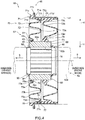
- Fig. 4 is a cross-sectional view along the axis, showing the schematic structure of a dust seal according to the second embodiment of the present invention.
- a component having a function that is the same as or similar to that of any component in the dust seal 1 according to the first embodiment of the present invention will be omitted and these components will be denoted by the same reference numeral as that corresponding component.
- a dust seal 50 has an annular shape centered about an axis x and includes a bushing 60, a dust seal body 70, a main seal lip 80, and a sub seal lip 90.
- the bushing 60 has an annular shape centered about the axis x, specifically a cylindrical shape, and includes an engaging part 62 at an end portion 61 which is the end portion of the bushing 60 on the inner side.
- the engaging part 62 includes a hollow circular disc 63, which projects toward the outer periphery direction from the end portion 61 and is in a flange form, and an annular projection 64, which projects toward the outer side from the end portion of the hollow circular disc 63 on the outer periphery side.
- the projection 64 faces an outer peripheral surface 60a of the bushing 60 in the radial direction, thereby forming an annular depression 65 depressed toward the inner side in the direction of the axis x between the projection 64 and the outer peripheral surface 60a.
- the bushing 60 includes trenches 18 on the inner peripheral surface 60b like the bushing 10 of the dust seal 1.
- the bushing 60 is made of a low-friction material like the bushing 10 of the dust seal 1.
- the dust seal body 70 includes an attaching portion 71, a first bellows (first accordion unit) 72, and a second bellows (second accordion unit) 73.
- the attaching portion 71 and the first bellows 72 are integrally formed from the same elastic material, e.g. rubber.
- the dust seal body 70 includes a metal reinforcing ring 24 in an annular shape centered about the axis x, like the dust seal body 20 of the dust seal 1.
- an end portion 71a which is the end portion of the attaching portion 71 on the inner side, has a flange 71b projecting toward the outer periphery direction and an annular projection 71c projecting toward the inner direction.
- the portion lying from the inner peripheral surface of the projection 71c to the vicinity of the end portion 71a of the inner peripheral surface 71d of the attaching portion 71 has a taper surface 71e which has a diameter decreasing toward the outer side in the direction of the axis x.
- a cylindrical retention surface 71f extending in the direction of the axis x is continuous with the taper surface 71c.
- the retention surface 71f extends until a step portion 71g that extends in the radial direction.
- the step portion 71g is a surface like a hollow circular disc and lies between the retention surface 71f and the inner peripheral surface 71d of the attaching portion 71.
- the first bellows 72 has concave and convex portions in the direction of the axis x and these concave and convex portions extend in an annular shape centered about the axis x and form an accordion elastic in a direction from the axis x direction to the radial direction.
- the first bellows 72 includes, in sequence from the inner periphery side, an annular concave portion 72a, which is concave toward the outer side, and an annular convex portion 72b, which joins to the concave portion 72a on the outer periphery side and is convex toward the inner side.
- first bellows 72 joins to the inner peripheral surface 71d of the attaching portion 71, at its end portion on the outer periphery side, i.e. at an end portion 72c, which is the end portion of the convex portion 72b on the outer periphery side.
- the first bellows 72 has a contact portion 74 at its end portion on the inner periphery side, i.e. at an end portion 72d, which is the end portion of the depression 72a on the inner periphery side.
- the contact portion 74 is an annular portion centered about the axis x and has a cylindrical surface 75 in a cylindrical shape about the axis x on the inner side of the contact portion 74.
- the cylindrical surface 75 is entirely in close contact with the outer peripheral surface 60a of the bushing 60.
- the contact portion 74 is bonded to the outer peripheral surface 60a of the bushing 60 at the cylindrical surface 75 by vulcanization.
- the accordion shape of the first bellows 72 may be the accordion shape of the first bellows 22 of the dust seal 1 (the convex portions 22a and 22c and the concave portion 22b) or any other shape allowing expansion and contraction in a direction from the axis x direction to the radial direction.
- the first bellows 72 may include the engaging part 25 of the first bellows 22 instead of the contact portion 74.
- the bushing 60 includes the projection 12 of the bushing 10 of the dust seal 1.
- the second bellows 73 is not integrally formed with the attaching portion 71 but formed as a separate part, and is fitted and fixed between the bushing 60 and the attaching portion 71 in the dust seal 50 as described later.
- the second bellows 73 has concave and convex portions in the direction of the axis x and these concave and convex portions extend in an annular shape centered about the axis x, and form an accordion elastic in a direction from the axis x direction to the radial direction.
- the second bellows 73 includes, in sequence from the inner periphery side, an annular convex portion 73a, which is convex toward the inner side direction, an annular concave portion 73b, which joins to the convex portion 73a on the outer periphery side and is concave toward the outer side direction, and an annular convex portions 73c, which joins to the concave portion 73b on the outer periphery side and is convex toward the inner side direction.
- These convex portions 73a and 73c and the concave portion 73b form the accordion.
- the accordion shape of the second bellows 73 may have a different shape elastic in a direction from the axis x direction to the radial direction.
- the second bellows 73 has a fitting part 76 at its end portion on the outer periphery side, i.e. at an end portion 73d, which is the end portion of the convex portion 73a on the outer periphery side.
- the fitting part 76 includes a fitting ring 77 having an annular shape centered about the axis x and an L-shaped cross section. As shown in Fig. 4 , the fitting ring 77 has, on the outer periphery side, a fitting surface 77a which is a cylindrical surface. The fitting ring 77 is fitted to and held on the retention surface 71f of the attaching portion 71 at the fitting surface 77a as described later.
- the fitting part 76 includes a holder 78 for holding the fitting ring 77.
- the shape of the holder 78 may be any shape that can hold the fitting ring 77.
- the fitting ring 77 is made of a metal, for example, stainless steel, SPCC (cold rolled steel sheet), or other metals.
- the second bellows 73 has an engaging part 79 at its end portion on the inner periphery side, i.e. at an end portion 73e, which is the end portion of the projection 73c on the inner periphery side.
- the engaging part 79 is an annular part extending in a U shape from the end portion 73e, is an annular part centered about the axis x having a U-shaped cross section opened toward the inner side.
- the engaging part 79 can be engaged with the engaging part 62 of the bushing 60 in such a manner that its end portion on the inner periphery side, i.e.
- a tip 79a is accommodated in a depression 65 of the engaging part 62 of the bushing 60. In this manner, with the engaging part 79, the end portion 73e of the second bellows 73 on the inner periphery side can easily be locked and fixed to the bushing 60.
- the second bellows 73 is fitted and fixed between the bushing 60 and the attaching portion 71.
- the tip 79a of the engaging part 79 of the inner periphery side of the second bellows 73 is accommodated in the depression 65 of the engaging part 62 of the bushing 60
- the projection 64 of the engaging part 62 is accommodated in a depression 79b of the engaging part 79
- the engaging part 62 and the engaging part 79 are engaged with each other, so that the second bellows 73 is locked to the bushing 60 through the engaging parts 79 and 62.
- the second bellows 73 is held in such a manner that the fitting part 76 on the outer periphery side is fitted to the retention surface 71f of the attaching portion 71.
- the fitting surface 77a of the fitting ring 77 of the fitting part 76 is in close contact with the retention surface 71f.
- the fitting ring 77 is in contact with the step portion 71g of the attaching portion 71 and positioned in the direction of the axis x.
- the projection 71c and the taper surface 71e are formed in the end portion 71a of the attaching portion 71, and the taper surface 71e has a circular conical surface having a diameter decreasing from the inner side toward the retention surface 71f.
- the fitting part 76 of the second bellows 73 can smoothly slide on the taper surface 71e to the retention surface 71f, which allows the fitting part 76 to be easily fitted to the attaching portion 71. Therefore, the assembly of the second bellows 73 can be simplified when the engaging part 79 is first engaged with the bushing 60 and the fitting part 76 is then fitted to the attaching portion 71.
- the second bellows 73 is made of the same material as the first bellows 72.
- the main seal lip 80 has the same mode as the seal lip 30 of the dust seal 1 and is joined to the outer-side surface of the end portion 66, which is the end portion of the bushing 60 on the outer side, by vulcanization bonding.
- the main seal lip 80 is made of the same material as the seal lip 30 and has sealing performance between the main seal lip 80 and the shaft such as wear resistance, heat resistance, following ability, and other abilities, and has muddy water resistance, and noise resistance.
- the sub seal lip 90 is a rubber component in an annular shape centered about the axis x, and its end portion on the outer side, i.e. an end portion 91, is joined to the end portion 61 of the bushing 60 on the outer side surface of the end portion 61.
- the sub seal lip 90 has a conical tubular shape the diameter of which decreases from the outer side toward the inner side and has a lip tip 92 at the end portion on the inner side.
- the lip tip 92 is configured to make close contact with and be slidable on the outer peripheral surface of the shaft inserted through the bushing 60 for sealing of the inside of the bushing 60 from the inner side in the usage state.
- a rubber suitable for sealing the sliding portion is used as the rubber material of the sub seal lip 90.
- a synthetic rubber such as nitrile rubber (NBR), hydrogenated nitrile rubber (H-NBR), acrylic rubber (ACM), fluoro-rubber (FKM), and the like. is used .
- the first bellows 72 is joined to the bushing 60 at the contact portion 74 by vulcanization bonding. Therefore, the bonding strength between the first bellows 72 and the bushing 60 can be heightened.
- the attaching portion 71 and the first bellows 72 are integrally formed from the same material. Therefore, the strength of the joint (end portion 72c) between the first bellows 72 and the attaching portion 71 can be heightened.
- the attaching portion 71, the first bellows 72, and the second bellows 73 are separated from the main seal lip 80 and the sub seal lip 90 and therefore a material with high fatigue resistance, which is different from sealing performance required to both of the seal lips 80 and 90, can be selected.
- the attaching portion 71, the first bellows 72, and the second bellows 73 are highly resistant against the above-described expansion and contraction, resulting in improved fatigue resistance against repeated expansion and contraction due to the movement of the bushing 60.
- the main seal lip 80 and the sub seal lip 90 are joined to the bushing 60 by vulcanization bonding, which provides high bonding strength between each of the seal lips 80 and 90 and the bushing 60.
- vulcanization bonding As the rubber material of the main seal lip 80 and the sub seal lip 90, differently from the rubber material of the dust seal body 70, a rubber suitable for sealing the sliding portion can be used, therefore, the sealing performance of the seal lips 80 and 90 can be improved. The durability of the seal lips 80 and 90 can also be improved.
- the attaching portion 71 and the first bellows 72 are integrally formed from the same rubber.
- the attaching portion 71 and the first bellows 72 are integrally molded by vulcanization of the same rubber.
- the bushing 60 and the reinforcing ring 24 molded into the shapes described above by a known method are placed in a mold in which the reinforcing ring 24 is bonded to the attaching portion 71 and the bushing 60 is bonded to the first bellows 72 by vulcanization.
- the contact portion 74 of the first bellows 72 is molded by vulcanization in a state in which the contact portion 74 contacts the outer peripheral surface 60a of the bushing 60 and is bonded thereto by vulcanization.
- the main seal lip 80 is formed at the end portion 66 of the bushing 60 by vulcanization molding.
- the molding of the main seal lip 80 may be performed either concurrently with the molding of the attaching portion 71 and the first bellows 72, before the molding of the attaching portion 71 and the first bellows 72, or after the molding of the attaching portion 71 and the first bellows 72.
- the sub seal lip 90 is formed at the end portion 61 of the bushing 60 by vulcanization molding.
- the molding of the sub seal lip 90 may be performed either concurrently with the molding of the attaching portion 71 and the first bellows 72, before the molding of the attaching portion 71 and the first bellows 72, or after the molding of the attaching portion 71 and the first bellows 72.
- the molding of the sub seal lip 90 may be, but is not necessarily, performed concurrently with the main seal lip 80.
- the second bellows 73 is molded by vulcanization. During this molding by vulcanization, the fitting ring 77 pre-formed by a known method is placed in a mold, so that the second bellows 73 is molded with the fitting ring 77, which is integral with the second bellows 73.
- the molded second bellows 73 is fixed between the bushing 60 and the attaching portion 71 in such manner that the engaging part 79 is engaged with the engaging part 62 of the bushing 60 and the fitting part 76 is fitted to the retention surface 71f of the attaching portion 71; thus, the dust seal 50 is completed. Since the attaching portion 71 has the taper surface 71e as described above, in this fitting step, the fitting step is simplified.
- the first bellows 72, the attaching portion 71, the bushing 60, the main seal lip 80, and the sub seal lip 90 are one component during assembly, resulting in a small number of components and a removal of a complex assembly process.
- the process for assembly of the dust seal 50 is simple.
- the dust seal 50 is attached to the column hole 41 to seal the gap between the steering shaft 42, which is inserted through the column hole 41, and the column hole 41, thereby preventing foreign matter such as dust, rain, or the like from entering the vehicle interior.
- a lip tip 92 is in close contact with the outer peripheral surface 42a of the steering shaft 42, thus the sub seal lip 90 seales the gap between the bushing 60 and the steering shaft 42 from the inner side (vehicle interior side) (see Fig. 4 ). Since the usage state of the dust seal 50 is similar to that of the above-described dust seal 1, its detailed description will be omitted.
- the dust seal 50 provides the same effects as the above-described dust seal 1.
- the attaching portion 71 and the main seal lip 80 by the attaching portion 71 and the main seal lip 80, foreign matter such as dust, rain, or the like are prevented from entering the vehicle interior from the gap between the column hole 41 and the steering shaft 42.
- the sub seal lip 90 used in addition to the main seal lip 80 prevents leakage of the lubricant applied between the bushing 60 and the steering shaft 42.
- first bellows 72 and the bushing 60 are strongly joined to each other by vulcanization bonding, thereby providing high durability against load repeatedly applied to the joint between the first bellows 72 and the bushing 60 due to the movement of the bushing 60, and therefore, the release of the joint between the first bellows 72 and the bushing 60 can be restrained.
- the attaching portion 71 and the first bellows 72 are integrally formed from the same material, thereby increasing the strength of the joint (the end portion 72c) between the first bellows 72 and the attaching portion 71, and therefore, the durability of the dust seal 50 against the load repeatedly applied to the joint can be increased.
- the durability of the attaching portion 71 and the first bellows 72 against load repeatedly applied thereto can be increased.
- the bushing 60 supports the steering shaft 42 with the inner peripheral surface extending lengthwise in the direction of the axis x, therefore, the bushing 60 can follow the movement of the steering shaft 42 and keep a stable position with respect to the steering shaft 42 even if the steering shaft 42 is largely off-center. Hence, it is possible to keep the contacting positions of the seal lips 80 and 90 to the steering shaft 42 a proper position.
- the dust seal 50 according to the second embodiment of the present invention can improve the fatigue resistance against repeated the expansion and contraction movement, therefore, it is possible to restrain damage to the dust seal body 70 due to the movement of the bushing 60.
- the risk of the detachment of the bushing 60 from the dust seal body 70 can be restrained sufficiently, the following ability of the bushing 60 to the steering shaft 42 can be maintained, and the positions of the seal lips 80 and 90 with respect to the steering shaft 42 can be kept a proper position. Therefore, the sealing performance of the main seal lip 80 and the sub seal lip 90 can be improved and maintained for a long period of time.
- the dust seal 50 according to the present embodiment can simplify the assembly process thereof and can increase the bonding strength between the bushing 60 and the first bellows 72.
- a modification of the dust seal 1 according to the first embodiment of the present invention will now be described with reference to Fig. 5 .
- the modification is different from the dust seal 1 in the shapes of the bushing 10, the first bellows 22, and the second bellows 23.
- a component having a function that is the same as or similar to that of any component of the dust seal 1 will be denoted by the same reference numeral as that corresponding component and its description will be omitted. Components different from those in the dust seal 1 will be described.
- Fig. 5 is a partial cross-sectional view along the axis x, showing the schematic structure of the modification of the dust seal 1 according to the first embodiment of the present invention.
- Fig. 5 shows the state before the second bellows 23 is engaged with a bushing 10A.
- the bushing 10A does not include the engaging part 17 but an annular trench 19 as a locking part.
- the trench 19 is formed on the outer peripheral surface 10a of the bushing 10A and is more on the inner side than the projection 12.
- the trench 19 is an annular trench depressed from the outer peripheral surface 10a of the bushing 10A toward the inner periphery side.
- the trench 19 has, for example, a rectangular cross section that allows a component accommodated in the trench 19 to be engaged therewith in the direction of the axis x.
- the first bellows 22 is used in a different mode.
- the shape of the engaging part 25 is different.
- the engaging part 25 formed at the end portion 22e which is the end portion of the first bellows 22 in the inner periphery side, has an annular depression 25a depressed toward the outer periphery side as described above.
- the depression 25a is defined by an annular inner side peripheral wall 25b, which is positioned on the inner side and projects toward the inner periphery side, and an annular outer side peripheral wall 25c, which is positioned on the outer side and projects toward the inner periphery side.
- the inner side peripheral wall 25b, in the cross section extends in the direction of the axis x, and, as shown in Fig.
- the outer side peripheral wall 25c has a rectangular cross section, like the engaging part 25 of the first bellows 22 shown in Fig. 2 .
- the mode of the second bellows 23 is different. Specifically, the engaging part at the end portion 23e is different from the aforementioned engaging part 26.
- the second bellows 23 is shown by the solid line in the state after the vulcanization molding in which the second bellows 23 has been molded such that the second bellows 23 extends diagonally from the inner peripheral surface 21d of the attaching portion 21 to the inner periphery side and the inner side, and shown by the virtual line in the usage state in which the second bellows 23 is locked to the bushing 10A.
- the end portion 23e of the second bellows 23 has a projecting tip 27 as an engaging part.
- the projecting tip 27 is formed such that it can be engaged with the trench 19 of the bushing 10A, is an annular portion projecting toward the inner side, and has a cross section shape, for example, a wedge shape projecting toward the inner side.
- the shape, in which the surface facing the outer periphery side extends from the base of the surface orthogonally with respect to the axis x or obliquely toward the outer periphery side is preferable.
- the second bellows 23 In the usage state, the second bellows 23 is bent toward the outer side, the projecting tip 27 of the second bellows 23 is fitted into the trench 19 of the bushing 10A, and the second bellows 23 is engaged and locked, and the second bellows 23 is joined and fixed to the bushing 10A.
- the convex portions 23a and 23c, and the concave portion 23b are formed as indicated by the virtual line in Fig. 5 .
- the second bellows 23 has elasticity given by the convex portions 23a and 23c, the concave portion 23b, and other components, therefore, the projecting tip 27 of the second bellows 23 does not come off the trench 19 and is pushed toward the inner periphery side in the trench 19.
- the projecting tip 27 of the second bellows 23 can be securely fitted into and engaged with the trench 19 of the bushing 10.
- the engaging part 25 of the first bellows 22 can be bonded by vulcanization bonding such that the engaging part 25 contacts the bushing 10A in a long range in the axis x direction via the inner peripheral surface 25d of the inner side peripheral wall 25b, in addition to the vulcanization bonding between the depression 25a and the projection 12 of the bushing 10A. Therefore, the contact area where the engaging part 25 of the first bellows 22 and the outer peripheral surface 10a of the bushing 10A can be increased and the bonding strength between the engaging part 25 of the first bellows 22 and the outer peripheral surface 10a of the bushing 10A can be increased.
- the second bellows 23 can be engaged with and joined to the bushing 10A for fixation; thus, the engagement of the second bellows 23 with the bushing 10A can be simplified. Therefore, the assembly of the dust seal 1 can be simplified.
- the projection 12 of the bushing 10A and the engaging part 25 of the first bellows 22, and the trench 19 of the bushing 10A and the projecting tip 27 of the second bellows 23 in this modification can also be used in the dust seal 2 according to the second embodiment of the present invention.
- the invention should not be limited to the aforementioned embodiments of the invention and includes various modes included in the scope of the concept of the invention and Claims.
- the structures can selectively be combined as appropriate so that at least part of the above-described solution and effects can be provided.
- the shape, material, position, size, and other conditions for each component in the above embodiments can be modified as appropriate according to the actual usage mode of the invention.
- the shapes such as the attaching portions 21 and 71, the reinforcing ring 24, the seal lips 30, 80, and 90, the accordion shape of the first and second bellows 22, 23, 72, and 73 and other components should not be limited to the above-described shapes.
- the shapes of the engaging part 25 of the first bellows 22 and the corresponding projection 12 of the bushing 10 should not necessarily be limited to the above-described shapes and may have any shape that allows the first bellows 22 to be engaged with the bushing 10 and bonded thereto by vulcanization at the end portion on the inner periphery side.
- the engaging part 25 of the first bellows 22 and the corresponding projection 12 of the bushing 10 may be configured like the joint (the contact portion 74 and the outer periphery 60a) between the first bellows 72 and the bushing 60 of the dust seal 50.
- the shapes of the contact portion 74 of the first bellows 72 should not necessarily be limited to the above-described shape and may be any shape that allows the first bellows 72 to be in contact or engaged with the bushing 60 and to be bonded thereto by vulcanization at the end portion on the inner periphery side.
- the contact portion 74 of the first bellows 72 and the bushing 60 may be configured like the engaging part 25 of the first bellows 22 and the corresponding projection 12 of the bushing 10 in the dust seal 1.
- the shapes of the engaging part 26 of the second bellows 23 and the corresponding engaging part 17 of the bushing 10 should not necessarily be limited to the above-described shape and may be any shape that allows the second bellows 23 to be engaged with the bushing 10 at the end portion on the inner periphery side.
- the shapes of the engaging part 79 of the second bellows 73 and the corresponding engaging part 62 of the bushing 60 should not necessarily be limited to the above-described shapes and may be any shape that allows the second bellows 73 to be engaged with the bushing 60 at the end portion on the inner periphery side.
- the shapes of the fitting part 76 of the second bellows 73 and the corresponding retention surface 71f of the attaching portion 71 should not necessarily be limited to the above-described shapes and may be any shape that allows the second bellows 73 to be fitted to the attaching portion 71 at the end portion on the outer periphery side.
- dust seals 1 and 50 according to the first and second embodiments of the present invention are used as a steering dust seal in a vehicle in the above description, the application of a dust seal of the invention should not be limited thereto and the invention can be applied to any structure that can use the effects of the invention, such as industrial machines.
Landscapes
- Engineering & Computer Science (AREA)
- General Engineering & Computer Science (AREA)
- Mechanical Engineering (AREA)
- Chemical & Material Sciences (AREA)
- Combustion & Propulsion (AREA)
- Transportation (AREA)
- Sealing Devices (AREA)
- Diaphragms And Bellows (AREA)
- Steering Controls (AREA)
- Vehicle Body Suspensions (AREA)
Abstract
Description
- The present invention relates to a dust seal for preventing entry of foreign matter such as dust, rain, or the like, and particularly relates to a steering dust seal for a steering shaft of a steering device for a car or other vehicles.
- In a steering device for a vehicle, e.g. a car, a steering shaft is inserted through a column hole opened in the dash panel separating the vehicle interior and the engine room. A gap between the steering shaft and the column hole is sealed with a steering dust seal. The steering dust seal prevents entry of foreign matter such as dust, rain, or the like to the vehicle interior.
-
Fig. 6 is a cross-sectional view schematically showing the structure of a conventional dust seal. As shown inFig. 6 , adust seal 100 as a conventional steering dust seal includes acylindrical bushing 101 made of a low-friction material, adust seal body 102 made of a rubber, aannular seal lip 103, which is present at an end portion of thebushing 101 adjacent to the engine room, and a attachingmember 104. - A
steering shaft 130 is inserted through thebushing 101, and thebushing 101 is slidable on thesteering shaft 130. Thedust seal body 102 includes a first bellows (accordion unit) 105 and asecond bellows 106, which project toward the engine room, and a cylindrical attachingportion 107 joined to the end portions of the first andsecond bellows metal reinforcing ring 108, which serves as a reinforcement conforming to the shape of the attachingportion 107, is embedded in the attachingportion 107. Aninner end portion 105a of thefirst bellows 105 and aninner end portion 106a of thesecond bellows 106 are fitted in the outer periphery of anend portion 101a of thebushing 101 adjacent to the vehicle interior. - The attaching
member 104 is an annular metal member that has a cross section in a generally L shape fitted in theinner end portion 105a on the inner side so as to cover theinner end portion 105a of thefirst bellows 105. Since the attachingmember 104 is fitted in theinner end portion 105a of thefirst bellows 105 in this manner, theinner end portion 105a of thefirst bellows 105 is locked in a direction toward the vehicle interior side and pushed toward the inner periphery side, therefore, thefirst bellows 105 is fixed to theend portion 101a of thebushing 101 adjacent to the vehicle interior, at theinner end portion 105a. In addition, as shown inFig. 6 , theinner end portion 106a of thesecond bellows 106 is locked in a direction toward the vehicle interior by theinner end portion 105a of thefirst bellows 105 fixed as described above, pushed toward the inner periphery side, and fixed to theend portion 101a of thebushing 101 adjacent to the vehicle interior. - The
seal lip 103, which is a rubber annular member, is disposed at theend portion 101b of thebushing 101 adjacent to the engine room and is slidably in contact with a surface of thesteering shaft 130. Theseal lip 103 prevents entry of foreign matter such as rain, dust or the like to a space between thesteering shaft 130 and thebushing 101, and leakage of a lubricant on the inner periphery of thebushing 101. - As shown in
Fig. 6 , in thedust seal 100, the attachingportion 107 of thedust seal body 102 is closely fitted in acolumn hole 132 of adash panel 131 for fixation to thecolumn hole 132 of thedash panel 131. Hence, entry of foreign matter such as rain, dust or the like in the gap between thedust seal 100 and thecolumn hole 132 is prevented (for example, see Patent Literature 1). - With this structure in the
conventional dust seal 100, thebushing 101 is movable with the first andsecond bellows steering shaft 130 is tilted or displaced and moves relatively to thecolumn hole 132 due to adjustment of the handle level or vibrations occurring while the car is running. However, the bushing 101 movable relatively to thecolumn hole 132 can follow the movement of thesteering shaft 130. This maintains the position of theseal lip 103 and thus works for ensuring prevention of entry of foreign matter such as rain, dust, or the like from the engine room to the vehicle interior. - Patent Literature 1: Japanese Patent No.
4987300 - In the
conventional dust seal 100, thebushing 101 is separated from thefirst bellows 105 and thesecond bellows 106, resulting in a large number of components and a complex assembly process of theconventional dust seal 100. In addition, thefirst bellows 105 and thesecond bellows 106 are attached to thebushing 101 by fitting the attachingmember 104, so that adequate attaching strength is not provided and the deviation or vibration of thesteering shaft 130 may unlock themounting member 104 and remove the fixation between each of thefirst bellows 105 and thesecond bellows 106 and thebushing 101. Even if the attachingmember 104 does not come off, loosened fixation between each of thefirst bellows 105 and thesecond bellows 106 and thebushing 101 prevents thebushing 101 and thus theseal lip 103 from staying in their proper positions, and there may be a problem with a decrease in sealing performance between theseal lip 103 and thesteering shaft 130. - It is an object of the present invention, which has been made to solve the above problem, to provide a dust seal which can be made with a simple assembly process and exhibits high joint strength between the bushing and each accordion unit.
- To achieve the above object, a dust seal of the present invention is a dust seal for sealing a gap between an opening in a receiving member and a shaft inserted through the opening, including: a dust seal body in an annular shape centered about an axis; a bushing in an annular shape centered about the axis, through which the shaft is slidably inserted; and a seal lip in an annular shape centered about the axis, provided at one end of the bushing in a direction of the axis, and slidably contacting an outer peripheral surface of the shaft, characterized in that the dust seal body including: an attaching portion that is fitted into the opening of the receiving portion, is in an annular shape centered about the axis, and is made of an elastic material, a first accordion unit that has an accordion made of an elastic material and is an annular shape centered about the axis, and a second accordion unit that has an accordion made of an elastic material and is an annular shape centered about the axis, the first accordion unit and the second accordion unit are arranged side by side in the direction of the axis, the first accordion unit is integral with the attaching portion, is joined to an inner peripheral surface of the attaching portion at an outer periphery, and is bonded to an outer peripheral surface of the bushing at an inner periphery by vulcanization, and the second accordion unit is fixed to the inner peripheral surface of the attaching portion at an outer periphery, and engaged with the outer peripheral surface of the bushing at an inner periphery.
- In the dust seal according to one aspect of the present invention, the second accordion unit is integral with the attaching portion and joined to the inner peripheral surface of the attaching portion at the outer periphery.
- In the dust seal according to one aspect of the present invention, the second accordion unit is fitted into the inner peripheral surface of the attaching portion at the outer periphery and to thereby be fixed to the attaching portion.
- In the dust seal according to one aspect of the present invention, the bushing includes a first engaging part extending in an annular shape along the outer peripheral surface, the second accordion unit includes an annular second engaging part at an end portion on the inner periphery, and the second accordion unit is locked to the outer peripheral surface of the bushing with the first engaging part and the second engaging part engaged with each other.
- In the dust seal according to one aspect of the present invention, the first engaging part includes a depression that extends in an annular shape along the outer peripheral surface of the bushing and that is depressed in the direction of the axis or toward the axis, the second engaging part includes a projection that extends in an annular shape at an end portion on the inner periphery of the second accordion unit and that projects in the direction of the axis, the projection of the second engaging part is accommodated in and engaged with the depression of the first engaging part, and the second accordion unit is locked to the outer peripheral surface of the bushing.
- In the dust seal according to one aspect of the present invention, the bushing includes, at an end portion on a second accordion unit side in the direction of the axis, a tapered portion with a taper surface spreading from the end portion side toward an end portion side opposite to the end portion side.
- A dust seal according to the present invention can be made with a simple assembly process and exhibits high joint strength between the bushing and each accordion unit.
-
-
Fig. 1 is a cross-sectional view along an axis, showing a schematic structure of a dust seal according to a first embodiment of the present invention. -
Fig. 2 is a partial cross-sectional view showing a state before a second bellows is engaged with a bushing in the dust seal according to the first embodiment of the present invention. -
Fig. 3 is a partial cross-sectional view showing a usage state of the dust seal according to the first embodiment of the present invention. -
Fig. 4 is a cross-sectional view along an axis, showing a schematic structure of a dust seal according to a second embodiment of the present invention. -
Fig. 5 is a partial cross-sectional view along the axis, showing a schematic structure of a modification of the dust seal according to the first embodiment of the present invention. -
Fig. 6 is a cross-sectional view schematically showing a structure of a conventional dust seal. - Embodiments according to the present invention will now be described with reference to the drawings.
-
Fig. 1 is a cross-sectional view along an axis, showing a schematic structure of a dust seal according to a first embodiment of the present invention. - As shown in
Fig. 1 , adust seal 1 according to the first embodiment of the present invention has an annular shape centered about an axis x and includes abushing 10, adust seal body 20, and aseal lip 30. Hereinafter, as shown inFig. 1 , the direction indicated by the arrow a in the direction of the axis x is referred to as the outer side or the engine room side, and the direction indicated by the arrow b in the direction of the axis x is referred to as the inner side or the vehicle interior side. The direction (indicated by the arrow c) getting closer to the axis x in the direction vertical to the axis x (hereinafter also referred to as the radial direction) is referred to as the inner periphery side, and the direction (indicated by the arrow d) getting further away from the axis x in the vertical direction to the axis x is referred to as the outer periphery side. - The
bushing 10 has an annular shape, specifically a cylindrical shape, having the axis x at its center and is made of a low-friction material. Since a shaft is slidably inserted through thebushing 10 in a usage state as described later, thebushing 10 has an inner diameter corresponding to the outer diameter of the shaft inserted therethrough. Anannular projection 12, projecting toward the outer periphery side, is provided on the outer peripheral surface of anend portion 11 which is the end portion of thebushing 10 on the outer side. Theprojection 12 extends on throughout the outer peripheral surface of theend portion 11, forming a flange on theend portion 11. Theprojection 12 functions as an engaging part as described later. Instead of theprojection 12 extending on throughout the outer peripheral surface of theend portion 11, a plurality of projections may be arranged at intervals in the circumferential direction in the form of an arc on a part of the periphery. Alternatively, theprojections 12 may be positioned more on the inner side than theend portion 11 in the direction of the axis x at a predetermined interval. - The
bushing 10 also includes atapered portion 14 at anend portion 13 which is the end portion on the inner side and opposite theend portion 11. Thetapered portion 14 includes ataper surface 15 which is a circular conical surface formed on the inner peripheral surface of theend portion 13 and having a diameter decreasing toward the outer side in the direction of the axis x; and ataper surface 16 which is a circular conical surface formed on the outer peripheral surface of theend portion 13 and having a diameter increasing toward the outer side in the direction of the axis x. As shown inFig. 1 , theend portion 13 projects to the outer periphery side further than an outerperipheral surface 10a between theend portions bushing 10, and is thicker than the portion between theend portions bushing 10. - As shown in
Fig. 1 , thebushing 10 includes anengaging part 17 at the edge of theend portion 13 on the outer periphery side and the outer side. Theengaging part 17 includes anannular projection 17a projecting toward the outer side. Theprojection 17a faces the outerperipheral surface 10a of thebushing 10 in the radial direction, forms anannular depression 17b depressed toward the inner side in the direction of the axis x between theprojection 17a and the outerperipheral surface 10a of thebushing 10. - A lubricant such as a grease or the like is applied to the inner
peripheral surface 10b of thebushing 10 on which a shaft (not shown in the drawing) slides. To hold the lubricant, a plurality oftrenches 18, extending in the direction of the axis x, is disposed at equal angular intervals in the circumferential direction. Thetrenches 18 should not necessarily be in the form of straight lines and may be in the helical, wave, or ring form, for example. Alternatively, asingle trench 18 may be formed. Thetrenches 18 hold the lubricant on the innerperipheral surface 10b of thebushing 10 to allow the shaft to be smoothly slidable for a long period of time. Note that thebushing 10 should not necessarily include thetrenches 18. - The
bushing 10 is made of a low-friction material as described above. Examples of the low-friction material include hard resin materials and metal materials. Examples of the resin materials include polyamide resins, polytetrafluoroethylene resins and the like. Examples of the metal materials include aluminum and the like. - The
dust seal body 20 includes an attachingportion 21, a first bellows (first accordion unit) 22, and a second bellows (second accordion unit) 23. The attachingportion 21 has an annular shape centered about the axis x, specifically a cylindrical shape, and is fitted in the opening in a receiving member as described later. The first bellows 22 has an annular shape centered about the axis x and is specifically a generally circular hollow disc shape and has portions depressed and projecting in the direction of the axis x. Similarly, the second bellows 23 has an annular shape centered about the axis x and is specifically a generally circular hollow disc shape and has portions depressed and projecting in the direction of the axis x. The first bellows 22 and the second bellows 23 are arranged side by side in the direction of the axis x, and the first bellows 22 is disposed further on the outer side than the second bellows 23. The first and second bellows 22 and 23 make thebushing 10 movable and their side-by-side arrangement gives sound insulation effects. The attachingportion 21, the first bellows 22, and the second bellows 23 are integrally formed from the same elastic material, e.g. rubber. Thedust seal body 20 includes ametal reinforcing ring 24 in an annular shape centered about the axis x. - As shown in
Fig. 1 , the attachingportion 21 has aflange 21a at the end portion of the attachingportion 21 on the inner side, and an outerperipheral surface 21c, which is the surface on the outer periphery side, exposed at anend portion 21b which is the end portion on the outer side. - The reinforcing
ring 24 is made of a metal, for example, stainless steel, steel SPCC(cold rolled steel sheet), or other metals, has a shape corresponding to the attachingportion 21, and is attached to the outer periphery side of the attachingportion 21. The reinforcingring 24 may be at least partly embedded in the attachingportion 21. In this embodiment, the reinforcingring 24 is embedded in the outer periphery side of the attachingportion 21 such that its end portion on the outer side is embedded in and covered with theoutside end portion 21b of the attachingportion 21, and the surface of its other portion on the outer periphery side is exposed. - When the
dust seal 1 is fitted in the opening in the receiving portion, the outerperipheral surface 21c of theouter end portion 21b of the attachingportion 21 and an outerperipheral surface 24a, which is the surface on the outer periphery side of the reinforcingring 24, come in close contact with the inner peripheral surface of the opening, thus sealing the gap between the receiving portion and thedust seal 1 as described later. - The first bellows 22 has concave and convex portions in the direction of the axis x and these concave and convex portions extend in a ring shape centered about the axis x, thereby forming an accordion elastic in the direction of the axis x and the radial direction. In particular, the first bellows 22 includes, in sequence from the inner periphery side, an annular
convex portion 22a, which is convex toward the inner side, an annularconcave portion 22b, which joins to theconvex portion 22a on the outer periphery side and is concave toward the outer side, and an annularconvex portion 22c, which joins to theconcave portion 22b on the outer periphery side and is convex toward the inner side. Theseconvex portions concave portion 22b form the accordion. The first bellows 22 joins to an innerperipheral surface 21d, which is the inner peripheral surface of the attachingportion 21, at its end portion on the outer periphery side, i.e. at anend portion 22d, which is the end portion of theconvex portion 22c on the outer periphery side. - Moreover, the first bellows 22 has an
engaging part 25 at its end portion on the inner periphery side, i.e. at anend portion 22e, which is the end portion of theconvex portion 22a on the inner periphery side. As shown inFig. 1 , the engagingpart 25 is an annular member having a generally U-shaped cross-section along the axis x (hereinafter simply referred to as cross-section) opened toward the inner periphery side. To be specific, the engagingpart 25 includes anannular depression 25a depressed toward the outer periphery side. Thedepression 25a can accommodate theprojection 12 of thebushing 10. In thedust seal 1, theprojection 12 is accommodated in thedepression 25a, thedepression 25a is engaged with theprojection 12, and theengaging part 25 is locked to theprojection 12. Moreover, the engagingpart 25 is bonded to theprojection 12 by vulcanization. To be specific, thedust seal body 20 is molded by vulcanization as described later. In the step of molding by vulcanization, thebushing 10 is placed in a mold, the first bellows 22 is molded in a state where the engagingpart 25 is engaged with theprojection 12 of thebushing 10 as described above, and theengaging part 25 and theprojection 12 are bonded to each other by vulcanization. - Similarly to the first bellows 22, the second bellows 23 has concave and convex portions in the direction of the axis x and these concave and convex portions extend in a ring shape centered about the axis x, thereby forming an accordion elastic in the direction of the axis x and the radial direction. In particular, the second bellows 23 includes, in sequence from the inner periphery side, an annular
convex portion 23a, which is convex toward the inner side, an annularconcave portion 23b, which joins to theconvex portion 23a on the outer periphery side and is concave toward the outer side, and an annularconvex portion 23c, which joins to theconcave portion 23b on the outer periphery side and is convex toward the inner side. Theseconvex portions concave portion 23b form the accordion. The second bellows 23 joins to the innerperipheral surface 21d of the attachingportion 21 at its end portion on the outer periphery side, i.e. at anend portion 23d, which is the end portion of theconvex portion 23c on the outer periphery side. - Moreover, the second bellows 23 has an
engaging part 26 at its end portion on the inner periphery side, i.e. at anend portion 23e, which is the end portion of theconvex portion 23a on the inner periphery side. As shown inFig. 1 , the engagingpart 26 includes acircular disc 26a, which projects toward the inner periphery side from theend portion 23e and is a hollow circular disc in a flange form, and anannular projection 26b projecting toward the inner side from the end portion of thecircular disc 26a on the inner periphery side. In theengaging part 26, theprojection 26b faces theconvex portion 23a in the radial direction in the vicinity of theend portion 23e, thereby forming anannular depression 26c depressed toward the outer side between theprojection 26b and theconvex portion 23a. - As shown in
Fig. 1 , in thedust seal 1, the engagingpart 26 of the second bellows 23 is engaged with the engagingpart 17 of thebushing 10, so that the second bellows 23 is locked and fixed to thebushing 10 at the engagingparts projection 26b of theengaging part 26 of the second bellows 23 is configured to be able to be accommodated in thedepression 17b of theengaging part 17 of thebushing 10. Theprojection 17a of theengaging part 17 of thebushing 10 is configured to be able to be accommodated in thedepression 26c of theengaging part 26 of the second bellows 23. Theprojection 26b is accommodated in thedepression 17b. Theprojection 17a is accommodated in thedepression 26c. Thus, the engagingpart 26 is locked to the engagingpart 17. By the locking between theengaging part 26 and theengaging part 17, the second bellows 23 is joined to thebushing 10. In this manner, the second bellows 23 is configured to be able to be joined to thebushing 10 at theengaging part 26 in a simple way and in a state in which the second bellows 23 and thebushing 10 do not easily disengage. - As described above, the
end portion 13 of thebushing 10 has the taperedportion 14, and thetaper surface 16 on the outer periphery side has a circular conical surface with a diameter expanding from the inner side toward the engagingpart 17. Accordingly, when thebushing 10 is inserted in the second bellows 23 from theend portion 13 and then the engagingpart 26 of the second bellows 23 is engaged with the engagingpart 17 of thebushing 10 as described above, the engagingpart 26 can slide on thetaper surface 16, thereby to allow thebushing 10 to be smoothly inserted in the second bellows 23. This facilitates engagement of theengaging part 26 of the second bellows 23 with the engagingpart 17 of thebushing 10. - As described later, the first bellows 22 and the second bellows 23, in the usage state, are repeatedly expanded and contracted radially in a direction from the direction of the axis x to the radial direction such that the
bushing 10 follows the movement of the shaft. For this reason, to the attachingportion 21, the first bellows 22, and the second bellows 23, fatigue resistance is required in addition to flexibility. Further, to the first bellows 22 and the second bellows 23, ozone resistance is also required. The rubber material for the attachingportion 21, the first bellows 22, and the second bellows 23 is ethylene-propylene rubber, for example. - The accordion shape (the
convex portions concave portion 22b) of the first bellows 22 should not necessarily be the above-described shape and may be any shape allowing expansion and contraction in a direction from the direction of the axis x to the radial direction. The shapes of theengaging part 25 of the first bellows 22 and theprojection 12 of thebushing 10 should not necessarily be the above-described shapes and may be any shapes that can be engaged with each other. - Similarly, the accordion shape (the
convex portions concave portion 23b) of the second bellows 23 should not necessarily be the above-described shape and may be any shape allowing expansion and contraction in a direction from the direction of the axis x to the radial direction. The shapes of theengaging part 26 of the second bellows 23 and theengaging part 17 of thebushing 10 should not necessarily be the above-described shapes and may be any shapes that can be engaged with each other. For example, instead of theprojection 26b of theengaging part 26 of the second bellows 23 extending in the circumferential direction throughout the periphery, a plurality of projections may be provided at intervals of equal angles in the circumferential direction in the form of an arc on a part of the periphery. Similarly, theprojection 17a of thebushing 10 may include a plurality of projections provided at intervals of equal angles in the circumferential direction corresponding to the plurality of projections of the second bellows 23. - The
seal lip 30 is an annular rubber component centered about the axis x, and theend portion 31, which is its end portion on the inner side, is joined to theend portion 11 of thebushing 10 at the surface of the edge portion 31on the outer side by vulcanization. Theseal lip 30 is in a generally conical tubular shape the diameter of which decreases from the inner side toward the outer side and includes, at theend portion 32 which is the end portion on the outer side, anannular lip tip 33 with a wedge-shaped cross section projecting toward the inner periphery side. As described later, thelip tip 33 is configured to make close contact with and to be slidable on the outer peripheral surface of the shaft inserted through thebushing 10 so that the inside of thebushing 10 is sealed in the usage state. - To the
seal lip 30, therefore, sealing performance between the seal lip and the shaft such as wear resistance, heat resistance, following ability, and other abilities are required. To theseal lip 30, durability against, for example, muddy water (muddy water resistance) and an ability to restrain noise due to the off-center shaft (noise resistance) are required. For this reason, theseal lip 30 is made of a rubber suitable for sealing the sliding portion, different from rubbers for the attachingportion 21 and the first and second bellows 22 and 23. Examples of the rubber for theseal lip 30 include synthetic rubbers such as nitrile rubber (NBR), hydrogenated nitrile rubber (H-NBR), acrylic rubber (ACM), fluoro-rubber (FKM), and the like. - As described above, in the
dust seal 1 according to the embodiment of the present invention, the first bellows 22 and thebushing 10 are joined to each other at theprojection 12 and theengaging part 25 by vulcanization bonding. This provides high bonding strength between the first bellows 22 and thebushing 10. - In the
dust seal body 20, the attachingportion 21, the first bellows 22, and the second bellows 23 are integrally formed from the same material. This provides high strength at the joint between the first bellows 22 and the attaching portion 21 (theend portion 22d) and the joint between the second bellows 23 and the attaching portion 21 (theend portion 23d). - The attaching
portion 21, the first bellows 22, and the second bellows 23 are separated from theseal lip 30 and therefore it is possible to choose a material having high fatigue resistance different from sealing performance required to theseal lip 30. - Consequently, in the
dust seal 1 according to the embodiment of the present invention, the attachingportion 21, the first bellows 22, and the second bellows 23 have high strength against the above-described expansion and contraction movement, resulting in improved fatigue resistance against repeated expansion and contraction due to the movement of thebushing 10. - In the
dust seal 1 according to the embodiment of the present invention, theseal lip 30 is joined to thebushing 10 by vulcanization bonding, which provides high bonding strength between theseal lip 30 and thebushing 10. Theseal lip 30 can be made of a rubber suitable for sealing a sliding portion, unlike a rubber material for thedust seal body 20, thereby improving the sealing performance of theseal lip 30. This also improves the durability of theseal lip 30. - A method of manufacturing the
dust seal 1 having the above structure will now be explained. The explanation for components that are manufactured by a known method will be omitted. - In the
dust seal body 20, the attachingportion 21, the first bellows 22, and the second bellows 23 are integrally formed from the same rubber. In particular, the attachingportion 21, the first bellows 22, and the second bellows 23 are integrally molded by vulcanization of the same rubber. In the molding by vulcanization, thebushing 10 and the reinforcingring 24 formed into the shapes described above by a known method are placed in a mold, and then, the reinforcingring 24 is bonded to the attachingportion 21 by vulcanization and thebushing 10 is bonded to the first bellows 22 by vulcanization. To be specific, the reinforcingring 24 is embedded in the attachingportion 21 and bonded thereto by vulcanization in the state where the end portion of the reinforcingring 24 on the outer side is covered by theend portion 21b of the attachingportion 21 and the surface of the other portion of the reinforcingring 24 on the outer periphery side is exposed. The engagingpart 25 of the first bellows 22 is molded and bonded to theprojection 12 of thebushing 10 by vulcanization in the manner in which the engagingpart 25 is engaged with theprojection 12. -
Fig. 2 is a partial cross-sectional view showing the state before the second bellows 23 is engaged with thebushing 10. To be specific,Fig. 2 shows the state of thedust seal body 20 and thebushing 10 molded by vulcanization. - As shown in
Fig. 2 , the first bellows 22 and the attachingportion 21 are molded by vulcanization into the same shape as in the completeddust seal 1 inFig. 1 . Meanwhile, as shown inFig. 2 , the second bellows 23 molded by vulcanization has a shape extending toward a direction away from the first bellows 22. In particular, the second bellows 23 is formed in such a shape that it extends diagonally from the innerperipheral surface 21d of the attachingportion 21 toward the inner periphery side and the inner side. After the second bellows 23 is molded by vulcanization, the shapes of theconvex portions concave portion 23b does not have the shape in the completed product. Thus, the shape of the second bellows 23 after the molding by vulcanization facilitates release from the mold. After the second bellows 23 is locked to thebushing 10, the second bellows 23 has the completed shape with theconvex portions concave portion 23b as shown inFig. 1 . - The
seal lip 30 is formed at theend portion 11 of thebushing 10 by the vulcanization molding. The molding of theseal lip 30 may be performed either concurrently with the molding of thedust seal body 20, before the molding of thedust seal body 20, or after the molding of thedust seal body 20. Since the rubber for theseal lip 30 is different from that for the attachingportion 21 and the first and second bellows 22 and 23 as described above, the molds for thedust seal body 20 and theseal lip 30 are not in communication with each other. - Consequently, the second bellows 23 in the state shown in
Fig. 2 is locked to thebushing 10, so that the second bellows 23 is joined to thebushing 10, thereby completing thedust seal 1. To be specific, the second bellows 23 is curved and theengaging part 26 is engaged with the engagingpart 17 of thebushing 10, thereby forming theconvex portions concave portion 23b in the second bellows 23 as shown inFig. 1 . Since thebushing 10 has the taperedportion 14 at theend portion 13 as described above in the step of engagement of the engagingparts - In the
dust seal 1, the first and second bellows 22 and 23, the attachingportion 21, thebushing 10, and theseal lip 30 are one component, resulting in a small number of components and a removal of a complex assembly process. Thus, the process for assembly of thedust seal 1 is simple. - The usage state of the
dust seal 1 having the structure described above will now be described.Fig. 3 is a partial cross-sectional view showing the usage state of thedust seal 1 according to the first embodiment of the present invention. Thedust seal 1 according to this embodiment is supposed to be used as a steering dust seal in a steering device of a vehicle, e.g. a car. - As shown in
Fig. 3 , thedust seal 1 is attached to acolumn hole 41 opened in adash panel 40 separating the vehicle interior and the engine room, in order to seal the gap between a steeringshaft 42, which is inserted through thecolumn hole 41, and thecolumn hole 41. Thedust seal 1 prevents foreign matter such as dust, rain, or the like from entering the vehicle interior. - The
dust seal 1 is fixed to thedash panel 40 with the attachingportion 21 fitted into thecolumn hole 41 with predetermined interference. The outerperipheral surface 21c of theend portion 21b of the attachingportion 21 and the outerperipheral surface 24a of the reinforcingring 24 are in close contact with thecolumn hole 41, thereby sealing the gap between thedash panel 40 and thedust seal 1. Theflange 21a of the attachingportion 21 is in contact with a vehicleinterior side surface 40a, which is a surface of thedash panel 40 on the vehicle interior side, so that thedust seal 1 is positioned in the direction of the axis x. - The steering
shaft 42 is inserted through thebushing 10 and the steeringshaft 42 is slidably supported by the innerperipheral surface 10b of thebushing 10. Since thebushing 10 supports the steeringshaft 42 with the innerperipheral surface 10b extending lengthwise in the direction of the axis x, thebushing 10 can follow the movement of the steeringshaft 42 and keep a stable position with respect to the steeringshaft 42 even if the steeringshaft 42 is largely off-center. This can keep a proper position of theseal lip 30 contacting the steeringshaft 42. A lubricant (not shown in the drawing) is applied to the innerperipheral surface 10b of thebushing 10, which enables smooth sliding of the steeringshaft 42. The outerperipheral surface 42a of the steeringshaft 42 is in close contact with thelip tip 33 of theseal lip 30, thereby sealing the gap between the steeringshaft 42 and thebushing 10 from the engine room. - In this manner, the attaching
portion 21 and theseal lip 30 seal the gap between thecolumn hole 41 and the steeringshaft 42, thereby preventing foreign matter such as dust, rain, or the like from entering the vehicle interior. - The steering
shaft 42 is tilted or displaced and moves relative to thecolumn hole 41 due to adjustment of the handle level and vibrations occurring while the car is running. Accordingly, with the movement of the steeringshaft 42, thebushing 10 moves relative to thecolumn hole 41. With the movement of thebushing 10, the first bellows 22 and the second bellows 23 expand and contract. This expansion and contraction of the first and second bellows 22 and 23 repeatedly applies load to the joint between the first bellows 22 and thebushing 10. As described above, the first bellows 22 and thebushing 10 are strongly joined to each other by vulcanization bonding at theprojection 12 and theengaging part 25, thereby providing high durability against load repeatedly applied to the joint between the first bellows 22 and thebushing 10 and restraining the release of the joint between the first bellows 22 and thebushing 10. - The attaching
portion 21, the first bellows 22, and the second bellows 23 are integrally formed from the same material, thereby increasing the strength at the joint (theend portion 22d) between the first bellows 22 and the attachingportion 21 and the joint (theend portion 23d) between the second bellows 23 and the attachingportion 21, therefore, it is possible to increase the durability of thedust seal 1 against the load repeatedly applied to the joints. - At the engaging
parts bushing 10, theprojections depressions bushing 10 are joined to each other, thereby increasing the strength of the joint between the second bellows 23 and thebushing 10. This increases the durability of thedust seal 1 against the load repeatedly applied to the joint. - In the
dust seal body 20, for the attachingportion 21, the first bellows 22, and the second bellows 23, a material with high fatigue resistance is selected, thereby increasing the durability of the attachingportion 21, the first bellows 22, and the second bellows 23 against load repeatedly applied to the attachingportion 21, the first bellows 22, and the second bellows 23. - In this manner, in the
dust seal 1 according to the embodiment, the bonding strength of the joint between each of the first and second bellows 22 and 23 and thebushing 10 and the bonding strength of the joint between each of the first and second bellows 22 and 23 and the attachingportion 21 are increased, and by the selection of the material for thedust seal body 20 the fatigue resistance is increased. Hence, the fatigue resistance against repeated expansion and contraction of thedust seal body 20 caused by the movement of thebushing 10 can be improved, whereby damage to thedust seal body 20 due to the movement of thebushing 10 can be restrained. - Hence, even in the event of an impact to the
bushing 10, the risk of the detachment of thebushing 10 from thedust seal body 20 can be sufficiently reduced, the ability of thebushing 10 to follow thesteering shaft 42 can be maintained, and the position of theseal lip 30 with respect to the steeringshaft 42 can be maintained at the proper position. Therefore, it is possible to improve the sealing performance of theseal lip 30 and maintain the sealing performance for a long period of time. - As described above, for the
dust seal 1 according to the present embodiment, the assembly process can be simplified and the bonding strength between thebushing 10 and each of the first and second bellows 22 and 23 can be increased. - The second embodiment of the present invention will now be described.
Fig. 4 is a cross-sectional view along the axis, showing the schematic structure of a dust seal according to the second embodiment of the present invention. Hereinafter, the description of a component having a function that is the same as or similar to that of any component in thedust seal 1 according to the first embodiment of the present invention will be omitted and these components will be denoted by the same reference numeral as that corresponding component. - As shown in
Fig. 4 , adust seal 50 according to the second embodiment of the present invention has an annular shape centered about an axis x and includes abushing 60, adust seal body 70, amain seal lip 80, and asub seal lip 90. - The
bushing 60 has an annular shape centered about the axis x, specifically a cylindrical shape, and includes anengaging part 62 at anend portion 61 which is the end portion of thebushing 60 on the inner side. The engagingpart 62 includes a hollow circular disc 63, which projects toward the outer periphery direction from theend portion 61 and is in a flange form, and an annular projection 64, which projects toward the outer side from the end portion of the hollow circular disc 63 on the outer periphery side. The projection 64 faces an outerperipheral surface 60a of thebushing 60 in the radial direction, thereby forming an annular depression 65 depressed toward the inner side in the direction of the axis x between the projection 64 and the outerperipheral surface 60a. Thebushing 60 includestrenches 18 on the innerperipheral surface 60b like thebushing 10 of thedust seal 1. Thebushing 60 is made of a low-friction material like thebushing 10 of thedust seal 1. - The
dust seal body 70 includes an attachingportion 71, a first bellows (first accordion unit) 72, and a second bellows (second accordion unit) 73. The attachingportion 71 and the first bellows 72 are integrally formed from the same elastic material, e.g. rubber. Thedust seal body 70 includes ametal reinforcing ring 24 in an annular shape centered about the axis x, like thedust seal body 20 of thedust seal 1. - As shown in
Fig. 4 , anend portion 71a, which is the end portion of the attachingportion 71 on the inner side, has aflange 71b projecting toward the outer periphery direction and anannular projection 71c projecting toward the inner direction. The portion lying from the inner peripheral surface of theprojection 71c to the vicinity of theend portion 71a of the innerperipheral surface 71d of the attachingportion 71 has ataper surface 71e which has a diameter decreasing toward the outer side in the direction of the axis x. Acylindrical retention surface 71f extending in the direction of the axis x is continuous with thetaper surface 71c. Theretention surface 71f extends until astep portion 71g that extends in the radial direction. Thestep portion 71g is a surface like a hollow circular disc and lies between theretention surface 71f and the innerperipheral surface 71d of the attachingportion 71. - Similarly to the first bellows 22 of the
dust seal 1, the first bellows 72 has concave and convex portions in the direction of the axis x and these concave and convex portions extend in an annular shape centered about the axis x and form an accordion elastic in a direction from the axis x direction to the radial direction. In particular, the first bellows 72 includes, in sequence from the inner periphery side, an annularconcave portion 72a, which is concave toward the outer side, and an annularconvex portion 72b, which joins to theconcave portion 72a on the outer periphery side and is convex toward the inner side. Theseconcave portion 72a and theconvex portion 72b form the accordion. Moreover, the first bellows 72 joins to the innerperipheral surface 71d of the attachingportion 71, at its end portion on the outer periphery side, i.e. at anend portion 72c, which is the end portion of theconvex portion 72b on the outer periphery side. - Moreover, the first bellows 72 has a
contact portion 74 at its end portion on the inner periphery side, i.e. at anend portion 72d, which is the end portion of thedepression 72a on the inner periphery side. As shown inFig. 4 , thecontact portion 74 is an annular portion centered about the axis x and has acylindrical surface 75 in a cylindrical shape about the axis x on the inner side of thecontact portion 74. Thecylindrical surface 75 is entirely in close contact with the outerperipheral surface 60a of thebushing 60. Thecontact portion 74 is bonded to the outerperipheral surface 60a of thebushing 60 at thecylindrical surface 75 by vulcanization. - The accordion shape of the first bellows 72 may be the accordion shape of the first bellows 22 of the dust seal 1 (the
convex portions concave portion 22b) or any other shape allowing expansion and contraction in a direction from the axis x direction to the radial direction. The first bellows 72 may include the engagingpart 25 of the first bellows 22 instead of thecontact portion 74. In this case, thebushing 60 includes theprojection 12 of thebushing 10 of thedust seal 1. - As shown in
Fig. 4 , unlike the second bellows 23 of thedust seal 1, the second bellows 73 is not integrally formed with the attachingportion 71 but formed as a separate part, and is fitted and fixed between thebushing 60 and the attachingportion 71 in thedust seal 50 as described later. The second bellows 73 has concave and convex portions in the direction of the axis x and these concave and convex portions extend in an annular shape centered about the axis x, and form an accordion elastic in a direction from the axis x direction to the radial direction. In particular, the second bellows 73 includes, in sequence from the inner periphery side, an annularconvex portion 73a, which is convex toward the inner side direction, an annularconcave portion 73b, which joins to theconvex portion 73a on the outer periphery side and is concave toward the outer side direction, and an annularconvex portions 73c, which joins to theconcave portion 73b on the outer periphery side and is convex toward the inner side direction. Theseconvex portions concave portion 73b form the accordion. It should be noted that the accordion shape of the second bellows 73 may have a different shape elastic in a direction from the axis x direction to the radial direction. - The second bellows 73 has a
fitting part 76 at its end portion on the outer periphery side, i.e. at anend portion 73d, which is the end portion of theconvex portion 73a on the outer periphery side. Thefitting part 76 includes afitting ring 77 having an annular shape centered about the axis x and an L-shaped cross section. As shown inFig. 4 , thefitting ring 77 has, on the outer periphery side, afitting surface 77a which is a cylindrical surface. Thefitting ring 77 is fitted to and held on theretention surface 71f of the attachingportion 71 at thefitting surface 77a as described later. Thefitting part 76 includes aholder 78 for holding thefitting ring 77. The shape of theholder 78 may be any shape that can hold thefitting ring 77. Thefitting ring 77 is made of a metal, for example, stainless steel, SPCC (cold rolled steel sheet), or other metals. - Moreover, the second bellows 73 has an
engaging part 79 at its end portion on the inner periphery side, i.e. at anend portion 73e, which is the end portion of theprojection 73c on the inner periphery side. As shown inFig. 4 , the engagingpart 79 is an annular part extending in a U shape from theend portion 73e, is an annular part centered about the axis x having a U-shaped cross section opened toward the inner side. As shown inFig. 4 , the engagingpart 79 can be engaged with the engagingpart 62 of thebushing 60 in such a manner that its end portion on the inner periphery side, i.e. atip 79a is accommodated in a depression 65 of theengaging part 62 of thebushing 60. In this manner, with the engagingpart 79, theend portion 73e of the second bellows 73 on the inner periphery side can easily be locked and fixed to thebushing 60. - As shown in
Fig. 4 , in thedust seal 50, the second bellows 73 is fitted and fixed between thebushing 60 and the attachingportion 71. In particular, thetip 79a of theengaging part 79 of the inner periphery side of the second bellows 73 is accommodated in the depression 65 of theengaging part 62 of thebushing 60, the projection 64 of theengaging part 62 is accommodated in adepression 79b of theengaging part 79, and theengaging part 62 and theengaging part 79 are engaged with each other, so that the second bellows 73 is locked to thebushing 60 through the engagingparts fitting part 76 on the outer periphery side is fitted to theretention surface 71f of the attachingportion 71. Thefitting surface 77a of thefitting ring 77 of thefitting part 76 is in close contact with theretention surface 71f. Thefitting ring 77 is in contact with thestep portion 71g of the attachingportion 71 and positioned in the direction of the axis x. - As described above, the
projection 71c and thetaper surface 71e are formed in theend portion 71a of the attachingportion 71, and thetaper surface 71e has a circular conical surface having a diameter decreasing from the inner side toward theretention surface 71f. Hence, thefitting part 76 of the second bellows 73 can smoothly slide on thetaper surface 71e to theretention surface 71f, which allows thefitting part 76 to be easily fitted to the attachingportion 71. Therefore, the assembly of the second bellows 73 can be simplified when the engagingpart 79 is first engaged with thebushing 60 and thefitting part 76 is then fitted to the attachingportion 71. - Like the first bellows 22 of the
dust seal 1, to the first bellows 72, in addition to flexibility, fatigue resistance is required, and ozone resistance is also required, and made of, for example, ethylene-propylene rubber. The second bellows 73 is made of the same material as the first bellows 72. - The
main seal lip 80 has the same mode as theseal lip 30 of thedust seal 1 and is joined to the outer-side surface of theend portion 66, which is the end portion of thebushing 60 on the outer side, by vulcanization bonding. Themain seal lip 80 is made of the same material as theseal lip 30 and has sealing performance between themain seal lip 80 and the shaft such as wear resistance, heat resistance, following ability, and other abilities, and has muddy water resistance, and noise resistance. - The
sub seal lip 90 is a rubber component in an annular shape centered about the axis x, and its end portion on the outer side, i.e. anend portion 91, is joined to theend portion 61 of thebushing 60 on the outer side surface of theend portion 61. Thesub seal lip 90 has a conical tubular shape the diameter of which decreases from the outer side toward the inner side and has alip tip 92 at the end portion on the inner side. Thelip tip 92 is configured to make close contact with and be slidable on the outer peripheral surface of the shaft inserted through thebushing 60 for sealing of the inside of thebushing 60 from the inner side in the usage state. - To the
sub seal lip 90, similarly to themain seal lip 80, sealing performance between thesub seal lip 90 and the shaft such as wear resistance, heat resistance, following ability, and other abilities is required, muddy water resistance, and noise resistance are also required. For this reason, like themain seal lip 80, as the rubber material of thesub seal lip 90, a rubber suitable for sealing the sliding portion is used. For example, a synthetic rubber such as nitrile rubber (NBR), hydrogenated nitrile rubber (H-NBR), acrylic rubber (ACM), fluoro-rubber (FKM), and the like. is used . - As described above, in the
dust seal 50 according to the second embodiment of the present invention, the first bellows 72 is joined to thebushing 60 at thecontact portion 74 by vulcanization bonding. Therefore, the bonding strength between the first bellows 72 and thebushing 60 can be heightened. - In the
dust seal body 70, the attachingportion 71 and the first bellows 72 are integrally formed from the same material. Therefore, the strength of the joint (endportion 72c) between the first bellows 72 and the attachingportion 71 can be heightened. - The attaching
portion 71, the first bellows 72, and the second bellows 73 are separated from themain seal lip 80 and thesub seal lip 90 and therefore a material with high fatigue resistance, which is different from sealing performance required to both of theseal lips - Consequently, in the
dust seal 50 according to the embodiment of the present invention, the attachingportion 71, the first bellows 72, and the second bellows 73 are highly resistant against the above-described expansion and contraction, resulting in improved fatigue resistance against repeated expansion and contraction due to the movement of thebushing 60. - In the
dust seal 50 according to the embodiment of the present invention, themain seal lip 80 and thesub seal lip 90 are joined to thebushing 60 by vulcanization bonding, which provides high bonding strength between each of theseal lips bushing 60. As the rubber material of themain seal lip 80 and thesub seal lip 90, differently from the rubber material of thedust seal body 70, a rubber suitable for sealing the sliding portion can be used, therefore, the sealing performance of theseal lips seal lips - A method of manufacturing the
dust seal 50 having the structure described above will now be described. It should be noted that the description of parts manufactured by a known method will be omitted. - In the
dust seal body 70, the attachingportion 71 and the first bellows 72 are integrally formed from the same rubber. In particular, the attachingportion 71 and the first bellows 72 are integrally molded by vulcanization of the same rubber. In the molding by vulcanization, thebushing 60 and the reinforcingring 24 molded into the shapes described above by a known method are placed in a mold in which the reinforcingring 24 is bonded to the attachingportion 71 and thebushing 60 is bonded to the first bellows 72 by vulcanization. In particular, thecontact portion 74 of the first bellows 72 is molded by vulcanization in a state in which thecontact portion 74 contacts the outerperipheral surface 60a of thebushing 60 and is bonded thereto by vulcanization. - Like the molding of the
seal lip 30, themain seal lip 80 is formed at theend portion 66 of thebushing 60 by vulcanization molding. The molding of themain seal lip 80 may be performed either concurrently with the molding of the attachingportion 71 and the first bellows 72, before the molding of the attachingportion 71 and the first bellows 72, or after the molding of the attachingportion 71 and the first bellows 72. - Like the molding of the
main seal lip 80, thesub seal lip 90 is formed at theend portion 61 of thebushing 60 by vulcanization molding. The molding of thesub seal lip 90 may be performed either concurrently with the molding of the attachingportion 71 and the first bellows 72, before the molding of the attachingportion 71 and the first bellows 72, or after the molding of the attachingportion 71 and the first bellows 72. The molding of thesub seal lip 90 may be, but is not necessarily, performed concurrently with themain seal lip 80. - The second bellows 73 is molded by vulcanization. During this molding by vulcanization, the
fitting ring 77 pre-formed by a known method is placed in a mold, so that the second bellows 73 is molded with thefitting ring 77, which is integral with the second bellows 73. - As described above, the molded second bellows 73 is fixed between the
bushing 60 and the attachingportion 71 in such manner that the engagingpart 79 is engaged with the engagingpart 62 of thebushing 60 and thefitting part 76 is fitted to theretention surface 71f of the attachingportion 71; thus, thedust seal 50 is completed. Since the attachingportion 71 has thetaper surface 71e as described above, in this fitting step, the fitting step is simplified. - In the
dust seal 50, the first bellows 72, the attachingportion 71, thebushing 60, themain seal lip 80, and thesub seal lip 90 are one component during assembly, resulting in a small number of components and a removal of a complex assembly process. Thus, the process for assembly of thedust seal 50 is simple. - Like the
dust seal 1, thedust seal 50 is attached to thecolumn hole 41 to seal the gap between the steeringshaft 42, which is inserted through thecolumn hole 41, and thecolumn hole 41, thereby preventing foreign matter such as dust, rain, or the like from entering the vehicle interior. Alip tip 92 is in close contact with the outerperipheral surface 42a of the steeringshaft 42, thus thesub seal lip 90 seales the gap between thebushing 60 and the steeringshaft 42 from the inner side (vehicle interior side) (seeFig. 4 ). Since the usage state of thedust seal 50 is similar to that of the above-describeddust seal 1, its detailed description will be omitted. - In the usage state, the
dust seal 50 provides the same effects as the above-describeddust seal 1. - To be specific, by the attaching
portion 71 and themain seal lip 80, foreign matter such as dust, rain, or the like are prevented from entering the vehicle interior from the gap between thecolumn hole 41 and the steeringshaft 42. In addition, thesub seal lip 90 used in addition to themain seal lip 80 prevents leakage of the lubricant applied between thebushing 60 and the steeringshaft 42. - In addition, the first bellows 72 and the
bushing 60 are strongly joined to each other by vulcanization bonding, thereby providing high durability against load repeatedly applied to the joint between the first bellows 72 and thebushing 60 due to the movement of thebushing 60, and therefore, the release of the joint between the first bellows 72 and thebushing 60 can be restrained. - The attaching
portion 71 and the first bellows 72 are integrally formed from the same material, thereby increasing the strength of the joint (theend portion 72c) between the first bellows 72 and the attachingportion 71, and therefore, the durability of thedust seal 50 against the load repeatedly applied to the joint can be increased. - In the
dust seal body 70, to the attachingportion 71 and the first bellows 72, a material with high fatigue resistance is selected, therefore, the durability of the attachingportion 71 and the first bellows 72 against load repeatedly applied thereto can be increased. - The
bushing 60 supports the steeringshaft 42 with the inner peripheral surface extending lengthwise in the direction of the axis x, therefore, thebushing 60 can follow the movement of the steeringshaft 42 and keep a stable position with respect to the steeringshaft 42 even if the steeringshaft 42 is largely off-center. Hence, it is possible to keep the contacting positions of theseal lips shaft 42 a proper position. - In this way, like the
dust seal 1, thedust seal 50 according to the second embodiment of the present invention can improve the fatigue resistance against repeated the expansion and contraction movement, therefore, it is possible to restrain damage to thedust seal body 70 due to the movement of thebushing 60. Hence, even in the event of an impact to thebushing 60, the risk of the detachment of thebushing 60 from thedust seal body 70 can be restrained sufficiently, the following ability of thebushing 60 to the steeringshaft 42 can be maintained, and the positions of theseal lips shaft 42 can be kept a proper position. Therefore, the sealing performance of themain seal lip 80 and thesub seal lip 90 can be improved and maintained for a long period of time. - As described above, the
dust seal 50 according to the present embodiment can simplify the assembly process thereof and can increase the bonding strength between thebushing 60 and the first bellows 72. - A modification of the
dust seal 1 according to the first embodiment of the present invention will now be described with reference toFig. 5 . The modification is different from thedust seal 1 in the shapes of thebushing 10, the first bellows 22, and the second bellows 23. A component having a function that is the same as or similar to that of any component of thedust seal 1 will be denoted by the same reference numeral as that corresponding component and its description will be omitted. Components different from those in thedust seal 1 will be described. -
Fig. 5 is a partial cross-sectional view along the axis x, showing the schematic structure of the modification of thedust seal 1 according to the first embodiment of the present invention.Fig. 5 shows the state before the second bellows 23 is engaged with abushing 10A. - As shown in
Fig. 5 , unlike thebushing 10, thebushing 10A does not include the engagingpart 17 but anannular trench 19 as a locking part. Thetrench 19 is formed on the outerperipheral surface 10a of thebushing 10A and is more on the inner side than theprojection 12. Thetrench 19 is an annular trench depressed from the outerperipheral surface 10a of thebushing 10A toward the inner periphery side. Thetrench 19 has, for example, a rectangular cross section that allows a component accommodated in thetrench 19 to be engaged therewith in the direction of the axis x. - In this modification, the first bellows 22 is used in a different mode. Specifically, the shape of the
engaging part 25 is different. The engagingpart 25 formed at theend portion 22e, which is the end portion of the first bellows 22 in the inner periphery side, has anannular depression 25a depressed toward the outer periphery side as described above. Thedepression 25a is defined by an annular inner sideperipheral wall 25b, which is positioned on the inner side and projects toward the inner periphery side, and an annular outer sideperipheral wall 25c, which is positioned on the outer side and projects toward the inner periphery side. The inner sideperipheral wall 25b, in the cross section, extends in the direction of the axis x, and, as shown inFig. 5 , has, for example, a triangle shape extending longwise in the direction of the axis x and forms an innerperipheral surface 25d, which is a cylindrical surface, on the inner periphery side. This innerperipheral surface 25d extends longwise in the axis x direction and is in contact with the outerperipheral surface 10a of thebushing 10A and bonded thereto by vulcanization bonding. In this modification, the innerperipheral surface 25d of the inner sideperipheral wall 25b extends from the inside end surface of theprojection 12 to the outside end portion of thetrench 19 and is bonded to the outerperipheral surface 10a of thebushing 10A in a long range in the direction of the axis x. The outer sideperipheral wall 25c has a rectangular cross section, like theengaging part 25 of the first bellows 22 shown inFig. 2 . - In addition, in this modification, the mode of the second bellows 23 is different. Specifically, the engaging part at the
end portion 23e is different from the aforementioned engagingpart 26. InFig. 5 , the second bellows 23 is shown by the solid line in the state after the vulcanization molding in which the second bellows 23 has been molded such that the second bellows 23 extends diagonally from the innerperipheral surface 21d of the attachingportion 21 to the inner periphery side and the inner side, and shown by the virtual line in the usage state in which the second bellows 23 is locked to thebushing 10A. - As shown in
Fig. 5 , theend portion 23e of the second bellows 23 has a projectingtip 27 as an engaging part. The projectingtip 27 is formed such that it can be engaged with thetrench 19 of thebushing 10A, is an annular portion projecting toward the inner side, and has a cross section shape, for example, a wedge shape projecting toward the inner side. In the free state of the second bellows 23 indicated by the solid line inFig. 5 , for the cross section shape of the projectingtip 27, the shape, in which the surface facing the outer periphery side extends from the base of the surface orthogonally with respect to the axis x or obliquely toward the outer periphery side is preferable. In the usage state, the second bellows 23 is bent toward the outer side, the projectingtip 27 of the second bellows 23 is fitted into thetrench 19 of thebushing 10A, and the second bellows 23 is engaged and locked, and the second bellows 23 is joined and fixed to thebushing 10A. At this time, in the second bellows 23, theconvex portions concave portion 23b are formed as indicated by the virtual line inFig. 5 . In this usage state, the second bellows 23 has elasticity given by theconvex portions concave portion 23b, and other components, therefore, the projectingtip 27 of the second bellows 23 does not come off thetrench 19 and is pushed toward the inner periphery side in thetrench 19. Thus, the projectingtip 27 of the second bellows 23 can be securely fitted into and engaged with thetrench 19 of thebushing 10. - As described above, in this modification, the engaging
part 25 of the first bellows 22 can be bonded by vulcanization bonding such that the engagingpart 25 contacts thebushing 10A in a long range in the axis x direction via the innerperipheral surface 25d of the inner sideperipheral wall 25b, in addition to the vulcanization bonding between thedepression 25a and theprojection 12 of thebushing 10A. Therefore, the contact area where the engagingpart 25 of the first bellows 22 and the outerperipheral surface 10a of thebushing 10A can be increased and the bonding strength between theengaging part 25 of the first bellows 22 and the outerperipheral surface 10a of thebushing 10A can be increased. Therefore, occurrence of breaking off and damage of the first bellows 22, during release of a mold after the vulcanization bonding between theengaging part 25 of the first bellows 22 and thebushing 10A in the manufacturing of thedust seal 10, can be restrained because of the high bonding strength between theengaging part 25 of the first bellows 22 and thebushing 10A. - In addition, only once the second bellows 23 is bent and the projecting
tip 27 is fitted in thetrench 19 of thebushing 10A, the second bellows 23 can be engaged with and joined to thebushing 10A for fixation; thus, the engagement of the second bellows 23 with thebushing 10A can be simplified. Therefore, the assembly of thedust seal 1 can be simplified. - It should be noted that the
projection 12 of thebushing 10A and theengaging part 25 of the first bellows 22, and thetrench 19 of thebushing 10A and the projectingtip 27 of the second bellows 23 in this modification can also be used in the dust seal 2 according to the second embodiment of the present invention. - Although the embodiments of the present invention have been described, the invention should not be limited to the aforementioned embodiments of the invention and includes various modes included in the scope of the concept of the invention and Claims. Moreover, the structures can selectively be combined as appropriate so that at least part of the above-described solution and effects can be provided. For example, the shape, material, position, size, and other conditions for each component in the above embodiments can be modified as appropriate according to the actual usage mode of the invention. In particular, the shapes such as the attaching
portions ring 24, theseal lips - As described above, in the
dust seal 1, the shapes of theengaging part 25 of the first bellows 22 and the correspondingprojection 12 of thebushing 10 should not necessarily be limited to the above-described shapes and may have any shape that allows the first bellows 22 to be engaged with thebushing 10 and bonded thereto by vulcanization at the end portion on the inner periphery side. The engagingpart 25 of the first bellows 22 and the correspondingprojection 12 of thebushing 10 may be configured like the joint (thecontact portion 74 and theouter periphery 60a) between the first bellows 72 and thebushing 60 of thedust seal 50. - Similarly, in the
dust seal 50, the shapes of thecontact portion 74 of the first bellows 72 should not necessarily be limited to the above-described shape and may be any shape that allows the first bellows 72 to be in contact or engaged with thebushing 60 and to be bonded thereto by vulcanization at the end portion on the inner periphery side. Moreover, thecontact portion 74 of the first bellows 72 and thebushing 60 may be configured like theengaging part 25 of the first bellows 22 and the correspondingprojection 12 of thebushing 10 in thedust seal 1. - Further, in the
dust seal 1, the shapes of theengaging part 26 of the second bellows 23 and the corresponding engagingpart 17 of thebushing 10 should not necessarily be limited to the above-described shape and may be any shape that allows the second bellows 23 to be engaged with thebushing 10 at the end portion on the inner periphery side. - Similarly, in the
dust seal 50, the shapes of theengaging part 79 of the second bellows 73 and the corresponding engagingpart 62 of thebushing 60 should not necessarily be limited to the above-described shapes and may be any shape that allows the second bellows 73 to be engaged with thebushing 60 at the end portion on the inner periphery side. Moreover, the shapes of thefitting part 76 of the second bellows 73 and thecorresponding retention surface 71f of the attachingportion 71 should not necessarily be limited to the above-described shapes and may be any shape that allows the second bellows 73 to be fitted to the attachingportion 71 at the end portion on the outer periphery side. - Although the dust seals 1 and 50 according to the first and second embodiments of the present invention are used as a steering dust seal in a vehicle in the above description, the application of a dust seal of the invention should not be limited thereto and the invention can be applied to any structure that can use the effects of the invention, such as industrial machines.
-
- 1,50,100
- dust seal
- 10,10A, 60,101
- bushing
- 10a, 60a
- outer peripheral surface
- 10b, 60b
- inner peripheral surface
- 11, 13, 61, 66, 101a, 101b
- end portion
- 12
- projection
- 14
- tapered portion
- 15,16
- taper surface
- 17, 62
- engaging part
- 17a, 64
- projection
- 17b, 65
- depression
- 18
- trench
- 19
- trench
- 20, 70,102
- dust seal body
- 21, 71,107
- attaching portion
- 21a, 71b
- flange
- 21b, 71a
- end portion
- 21c
- outer peripheral surface
- 21d, 71d
- inner peripheral surface
- 22, 72,105
- first bellows
- 22a, 22c, 23a, 23c, 72b, 73a, 73c
- convex portion
- 22b, 23b, 72a, 73b
- concave portion
- 22d, 22e, 23d, 23e, 72c, 72d, 73d, 73e
- end portion
- 23, 73,106
- second bellows
- 24,108
- reinforcing ring
- 24a
- outer peripheral surface
- 25, 26, 79
- engaging part
- 25a
- depression
- 25b
- inner side peripheral wall
- 25c
- outer side peripheral wall
- 25d
- inner peripheral surface
- 26a
- circular disc
- 26b
- projection
- 26c
- depression
- 27
- projecting tip
- 30, 103
- seal lip
- 31,32
- end portion
- 33
- lip tip
- 40, 131
- dash panel
- 40a
- vehicle interior side surface
- 41, 132
- column hole
- 42, 130
- steering shaft
- 42a
- outer periphery
- 63
- hollow circular disc
- 71c
- projection
- 71e
- taper surface
- 71f
- retention surface
- 71g
- step portion
- 74
- contact portion
- 75
- cylindrical surface
- 76
- fitting part
- 77
- fitting ring
- 77a
- fitting surface
- 78
- holder
- 79a
- tip
- 79b
- depression
- 80
- main seal lip
- 90
- sub seal lip
- 91
- end portion
- 92
- lip tip
- 104
- attaching member
- 105a, 106a
- inner end portion
- x
- axis
Claims (6)
- A dust seal for sealing a gap between an opening in a receiving member and a shaft inserted through the opening, comprising:a dust seal body in an annular shape centered about an axis;a bushing in an annular shape centered about the axis, through which the shaft is slidably inserted; anda seal lip in an annular shape centered about the axis, provided at one end of the bushing in a direction of the axis, and slidably contacting an outer peripheral surface of the shaft, characterized in thatthe dust seal body including:an attaching portion that is fitted into the opening of the receiving portion, is in an annular shape centered about the axis, and is made of an elastic material,a first accordion unit that has an accordion made of an elastic material and is an annular shape centered about the axis, anda second accordion unit that has an accordion made of an elastic material and is an annular shape centered about the axis,the first accordion unit and the second accordion unit are arranged side by side in the direction of the axis,the first accordion unit is integral with the attaching portion, is joined to an inner peripheral surface of the attaching portion at an outer periphery, and is bonded to an outer peripheral surface of the bushing at an inner periphery by vulcanization, andthe second accordion unit is fixed to the inner peripheral surface of the attaching portion at an outer periphery, and engaged with the outer peripheral surface of the bushing at an inner periphery.
- The dust seal according to Claim 1, wherein the second accordion unit is integral with the attaching portion and joined to the inner peripheral surface of the attaching portion at the outer periphery.
- The dust seal according to Claim 1, wherein the second accordion unit is fitted into the inner peripheral surface of the attaching portion at the outer periphery and to thereby be fixed to the attaching portion.
- The dust seal according to any one of Claims 1 to 3, wherein the bushing includes a first engaging part extending in an annular shape along the outer peripheral surface, the second accordion unit includes an annular second engaging part at an end portion on the inner periphery, and the second accordion unit is locked to the outer peripheral surface of the bushing with the first engaging part and the second engaging part engaged with each other.
- The dust seal according to Claim 4, wherein the first engaging part includes a depression that extends in an annular shape along the outer peripheral surface of the bushing and that is depressed in the direction of the axis or toward the axis, the second engaging part includes a projection that extends in an annular shape at the end portion on the inner periphery of the second accordion unit and that projects in the direction of the axis, the projection of the second engaging part is accommodated in and engaged with the depression of the first engaging part, and the second accordion unit is locked to the outer peripheral surface of the bushing.
- The dust seal according to Claim 4 or 5, wherein the bushing includes, at an end portion on a second accordion unit side in the direction of the axis, a tapered portion with a taper surface spreading from the end portion side toward an end portion side opposite to the end portion side.
Applications Claiming Priority (2)
| Application Number | Priority Date | Filing Date | Title |
|---|---|---|---|
| JP2014228732 | 2014-11-11 | ||
| PCT/JP2015/081125 WO2016076186A1 (en) | 2014-11-11 | 2015-11-05 | Dust seal |
Publications (3)
| Publication Number | Publication Date |
|---|---|
| EP3214349A1 true EP3214349A1 (en) | 2017-09-06 |
| EP3214349A4 EP3214349A4 (en) | 2018-05-30 |
| EP3214349B1 EP3214349B1 (en) | 2020-03-18 |
Family
ID=55954275
Family Applications (1)
| Application Number | Title | Priority Date | Filing Date |
|---|---|---|---|
| EP15859612.2A Active EP3214349B1 (en) | 2014-11-11 | 2015-11-05 | Dust seal |
Country Status (5)
| Country | Link |
|---|---|
| US (1) | US10234037B2 (en) |
| EP (1) | EP3214349B1 (en) |
| JP (1) | JP6683130B2 (en) |
| CN (1) | CN107110355B (en) |
| WO (1) | WO2016076186A1 (en) |
Families Citing this family (26)
| Publication number | Priority date | Publication date | Assignee | Title |
|---|---|---|---|---|
| EP3214349B1 (en) * | 2014-11-11 | 2020-03-18 | Nok Corporation | Dust seal |
| US10393298B2 (en) | 2016-02-01 | 2019-08-27 | Deublin Company | Rotary union with expanding ring |
| GB201601820D0 (en) * | 2016-02-02 | 2016-03-16 | Rolls Royce Power Eng | An arrangement for adjoining a support structure to a pipe |
| KR101819143B1 (en) * | 2016-12-13 | 2018-02-28 | 주식회사 디엠씨 | Integral type dust cover with bearings |
| CN107051794B (en) * | 2017-05-08 | 2021-01-08 | 常州铭赛机器人科技股份有限公司 | Fluid micro-injection device and flow channel assembly thereof |
| WO2018205682A1 (en) | 2017-05-08 | 2018-11-15 | 常州铭赛机器人科技股份有限公司 | Fluid micro-injection device and flow channel assembly |
| KR101865190B1 (en) * | 2017-11-28 | 2018-06-08 | (주)건화이엔지 | A compact boot of constant velocity joint |
| WO2020021934A1 (en) * | 2018-07-25 | 2020-01-30 | Nok株式会社 | Sealing device |
| CN112105852B (en) * | 2018-07-25 | 2023-04-04 | Nok株式会社 | Sealing device |
| DE102018213483A1 (en) * | 2018-08-10 | 2020-02-13 | Icotek Project Gmbh & Co. Kg | grommet |
| JP6998915B2 (en) * | 2019-05-09 | 2022-01-18 | 矢崎総業株式会社 | Grommets and wire harnesses |
| EP3750780B1 (en) * | 2019-06-12 | 2021-06-23 | Etimex Technical Components GmbH | Steering column feedthrough of a steerable vehicle |
| CN113825934B (en) * | 2019-06-12 | 2024-09-13 | Nok株式会社 | Sealing device |
| US12515777B2 (en) | 2019-08-05 | 2026-01-06 | Tides Marine, Inc. | Shaft seal |
| JP7342631B2 (en) * | 2019-11-07 | 2023-09-12 | 日本精工株式会社 | Outer tube with hole cover |
| JP7052787B2 (en) * | 2019-11-15 | 2022-04-12 | 日本精工株式会社 | Dust cover |
| JP7351192B2 (en) * | 2019-11-20 | 2023-09-27 | 日本精工株式会社 | dust cover |
| US11626716B2 (en) * | 2019-12-20 | 2023-04-11 | Raymond & Lae Engineering, Inc. | Floor grommet |
| WO2021133584A1 (en) * | 2019-12-27 | 2021-07-01 | Saint-Gobain Performance Plastics Corporation | Dynamic seal |
| JP7077347B2 (en) * | 2020-02-17 | 2022-05-30 | 矢崎総業株式会社 | Grommets and wire harnesses |
| DE102020204526A1 (en) * | 2020-04-08 | 2021-10-14 | Icotek Project Gmbh & Co. Kg | Device for the implementation and strain relief of strands |
| JP7514734B2 (en) * | 2020-11-04 | 2024-07-11 | 日本精工株式会社 | Dust cover |
| JP7564541B2 (en) * | 2021-02-12 | 2024-10-09 | Nskステアリング&コントロール株式会社 | Dust cover |
| JPWO2023074679A1 (en) * | 2021-10-26 | 2023-05-04 | ||
| DE102022206783B4 (en) * | 2022-07-04 | 2026-04-30 | Volkswagen Aktiengesellschaft | Insertion element for inserting and positioning a shaft element, system with the insertion element, a method for assembling the system, and a method for replacing a component in the system |
| CN222721060U (en) * | 2024-04-22 | 2025-04-04 | 刘志勇 | Wire-embedding box for wire and cable wall |
Family Cites Families (12)
| Publication number | Priority date | Publication date | Assignee | Title |
|---|---|---|---|---|
| JPH0942467A (en) * | 1995-07-31 | 1997-02-14 | Toyota Motor Corp | Column hole cover |
| JP2000032208A (en) * | 1998-07-13 | 2000-01-28 | Ricoh Co Ltd | Bookbinding Document Scanner |
| JP2001324018A (en) * | 2000-05-12 | 2001-11-22 | Kurashiki Kako Co Ltd | Dust seal |
| US20020113375A1 (en) * | 2001-02-20 | 2002-08-22 | Gennady Ruderman | Pressure differential sealing device |
| US7641561B2 (en) * | 2004-01-15 | 2010-01-05 | Nsk Ltd. | Dust cover for a steering shaft |
| JP5120763B2 (en) * | 2006-07-05 | 2013-01-16 | Nok株式会社 | Sealing device |
| EP2088352B1 (en) * | 2006-11-21 | 2013-07-17 | NOK Corporation | Sealing device |
| DE102008038997A1 (en) * | 2008-08-08 | 2010-02-18 | Sms Siemag Aktiengesellschaft | Sealing element for sealing a roller bearing, roller bearings and method for mounting the sealing element |
| CN201824966U (en) * | 2010-09-29 | 2011-05-11 | 奇瑞汽车股份有限公司 | Steering sheath |
| DE102011105449A1 (en) * | 2011-06-22 | 2012-12-27 | GM Global Technology Operations LLC (n. d. Gesetzen des Staates Delaware) | Double-walled annular seal element for sealing gap between passage opening in front wall and shaft of steering of motor car, has radial pre-tensioned inner sealing rings biasing against shaft and assigned with respective sealing diaphragms |
| EP3214349B1 (en) * | 2014-11-11 | 2020-03-18 | Nok Corporation | Dust seal |
| WO2016076087A1 (en) * | 2014-11-14 | 2016-05-19 | Nok株式会社 | Dust seal |
-
2015
- 2015-11-05 EP EP15859612.2A patent/EP3214349B1/en active Active
- 2015-11-05 CN CN201580061459.5A patent/CN107110355B/en not_active Expired - Fee Related
- 2015-11-05 WO PCT/JP2015/081125 patent/WO2016076186A1/en not_active Ceased
- 2015-11-05 JP JP2016559000A patent/JP6683130B2/en active Active
-
2017
- 2017-04-20 US US15/492,383 patent/US10234037B2/en active Active
Also Published As
| Publication number | Publication date |
|---|---|
| CN107110355A (en) | 2017-08-29 |
| JPWO2016076186A1 (en) | 2017-08-17 |
| JP6683130B2 (en) | 2020-04-15 |
| CN107110355B (en) | 2019-12-31 |
| US10234037B2 (en) | 2019-03-19 |
| EP3214349B1 (en) | 2020-03-18 |
| EP3214349A4 (en) | 2018-05-30 |
| WO2016076186A1 (en) | 2016-05-19 |
| US20170219100A1 (en) | 2017-08-03 |
Similar Documents
| Publication | Publication Date | Title |
|---|---|---|
| EP3214349B1 (en) | Dust seal | |
| EP3211279A1 (en) | Dust seal | |
| EP1710147B1 (en) | Dust cover for steering shaft | |
| KR101405355B1 (en) | Sealing device | |
| CN106133413B (en) | Gasket | |
| KR20070089229A (en) | Sealing device with soundproof seal | |
| JP2011085257A (en) | Dust cover for ball joint | |
| EP1890057A1 (en) | Sealing device | |
| EP2778446A1 (en) | Dust cover for ball joint | |
| CN113825934B (en) | Sealing device | |
| EP2730757B1 (en) | Valve stem seal device | |
| JP2008032208A (en) | Sealing device | |
| JP2014137122A (en) | Sealing device | |
| JP6460574B2 (en) | Dust seal | |
| EP2937581A1 (en) | Ball joint dust cover | |
| JP2011149512A (en) | Clutch piston for torque converter | |
| JP2000266192A (en) | Installing structure of dust boot | |
| JP2010223251A (en) | Sealing device | |
| JP2016109174A (en) | Dust cover | |
| JP6402593B2 (en) | Sealing device with sound insulation seal | |
| JP2016173161A (en) | Sealing device | |
| JP2005147335A (en) | Oil seal device | |
| JP2007245914A (en) | Center bearing support | |
| JP2006083975A (en) | Mounting structure of sealing device | |
| JP2017215010A (en) | Sealing device |
Legal Events
| Date | Code | Title | Description |
|---|---|---|---|
| STAA | Information on the status of an ep patent application or granted ep patent |
Free format text: STATUS: THE INTERNATIONAL PUBLICATION HAS BEEN MADE |
|
| PUAI | Public reference made under article 153(3) epc to a published international application that has entered the european phase |
Free format text: ORIGINAL CODE: 0009012 |
|
| STAA | Information on the status of an ep patent application or granted ep patent |
Free format text: STATUS: REQUEST FOR EXAMINATION WAS MADE |
|
| 17P | Request for examination filed |
Effective date: 20170427 |
|
| AK | Designated contracting states |
Kind code of ref document: A1 Designated state(s): AL AT BE BG CH CY CZ DE DK EE ES FI FR GB GR HR HU IE IS IT LI LT LU LV MC MK MT NL NO PL PT RO RS SE SI SK SM TR |
|
| AX | Request for extension of the european patent |
Extension state: BA ME |
|
| DAV | Request for validation of the european patent (deleted) | ||
| DAX | Request for extension of the european patent (deleted) | ||
| A4 | Supplementary search report drawn up and despatched |
Effective date: 20180426 |
|
| RIC1 | Information provided on ipc code assigned before grant |
Ipc: F16J 15/54 20060101ALI20180420BHEP Ipc: F16J 15/3204 20160101ALI20180420BHEP Ipc: B62D 1/20 20060101ALI20180420BHEP Ipc: F16J 15/52 20060101ALI20180420BHEP Ipc: F16J 15/3224 20160101ALI20180420BHEP Ipc: F16J 3/04 20060101AFI20180420BHEP Ipc: B62D 1/16 20060101ALI20180420BHEP |
|
| GRAP | Despatch of communication of intention to grant a patent |
Free format text: ORIGINAL CODE: EPIDOSNIGR1 |
|
| STAA | Information on the status of an ep patent application or granted ep patent |
Free format text: STATUS: GRANT OF PATENT IS INTENDED |
|
| INTG | Intention to grant announced |
Effective date: 20191021 |
|
| GRAS | Grant fee paid |
Free format text: ORIGINAL CODE: EPIDOSNIGR3 |
|
| GRAA | (expected) grant |
Free format text: ORIGINAL CODE: 0009210 |
|
| STAA | Information on the status of an ep patent application or granted ep patent |
Free format text: STATUS: THE PATENT HAS BEEN GRANTED |
|
| AK | Designated contracting states |
Kind code of ref document: B1 Designated state(s): AL AT BE BG CH CY CZ DE DK EE ES FI FR GB GR HR HU IE IS IT LI LT LU LV MC MK MT NL NO PL PT RO RS SE SI SK SM TR |
|
| REG | Reference to a national code |
Ref country code: GB Ref legal event code: FG4D |
|
| REG | Reference to a national code |
Ref country code: DE Ref legal event code: R096 Ref document number: 602015049163 Country of ref document: DE |
|
| REG | Reference to a national code |
Ref country code: AT Ref legal event code: REF Ref document number: 1246261 Country of ref document: AT Kind code of ref document: T Effective date: 20200415 Ref country code: IE Ref legal event code: FG4D |
|
| PG25 | Lapsed in a contracting state [announced via postgrant information from national office to epo] |
Ref country code: FI Free format text: LAPSE BECAUSE OF FAILURE TO SUBMIT A TRANSLATION OF THE DESCRIPTION OR TO PAY THE FEE WITHIN THE PRESCRIBED TIME-LIMIT Effective date: 20200318 Ref country code: RS Free format text: LAPSE BECAUSE OF FAILURE TO SUBMIT A TRANSLATION OF THE DESCRIPTION OR TO PAY THE FEE WITHIN THE PRESCRIBED TIME-LIMIT Effective date: 20200318 Ref country code: NO Free format text: LAPSE BECAUSE OF FAILURE TO SUBMIT A TRANSLATION OF THE DESCRIPTION OR TO PAY THE FEE WITHIN THE PRESCRIBED TIME-LIMIT Effective date: 20200618 |
|
| REG | Reference to a national code |
Ref country code: NL Ref legal event code: MP Effective date: 20200318 |
|
| PG25 | Lapsed in a contracting state [announced via postgrant information from national office to epo] |
Ref country code: BG Free format text: LAPSE BECAUSE OF FAILURE TO SUBMIT A TRANSLATION OF THE DESCRIPTION OR TO PAY THE FEE WITHIN THE PRESCRIBED TIME-LIMIT Effective date: 20200618 Ref country code: HR Free format text: LAPSE BECAUSE OF FAILURE TO SUBMIT A TRANSLATION OF THE DESCRIPTION OR TO PAY THE FEE WITHIN THE PRESCRIBED TIME-LIMIT Effective date: 20200318 Ref country code: LV Free format text: LAPSE BECAUSE OF FAILURE TO SUBMIT A TRANSLATION OF THE DESCRIPTION OR TO PAY THE FEE WITHIN THE PRESCRIBED TIME-LIMIT Effective date: 20200318 Ref country code: SE Free format text: LAPSE BECAUSE OF FAILURE TO SUBMIT A TRANSLATION OF THE DESCRIPTION OR TO PAY THE FEE WITHIN THE PRESCRIBED TIME-LIMIT Effective date: 20200318 Ref country code: GR Free format text: LAPSE BECAUSE OF FAILURE TO SUBMIT A TRANSLATION OF THE DESCRIPTION OR TO PAY THE FEE WITHIN THE PRESCRIBED TIME-LIMIT Effective date: 20200619 |
|
| REG | Reference to a national code |
Ref country code: LT Ref legal event code: MG4D |
|
| PG25 | Lapsed in a contracting state [announced via postgrant information from national office to epo] |
Ref country code: NL Free format text: LAPSE BECAUSE OF FAILURE TO SUBMIT A TRANSLATION OF THE DESCRIPTION OR TO PAY THE FEE WITHIN THE PRESCRIBED TIME-LIMIT Effective date: 20200318 |
|
| PG25 | Lapsed in a contracting state [announced via postgrant information from national office to epo] |
Ref country code: PT Free format text: LAPSE BECAUSE OF FAILURE TO SUBMIT A TRANSLATION OF THE DESCRIPTION OR TO PAY THE FEE WITHIN THE PRESCRIBED TIME-LIMIT Effective date: 20200812 Ref country code: LT Free format text: LAPSE BECAUSE OF FAILURE TO SUBMIT A TRANSLATION OF THE DESCRIPTION OR TO PAY THE FEE WITHIN THE PRESCRIBED TIME-LIMIT Effective date: 20200318 Ref country code: SK Free format text: LAPSE BECAUSE OF FAILURE TO SUBMIT A TRANSLATION OF THE DESCRIPTION OR TO PAY THE FEE WITHIN THE PRESCRIBED TIME-LIMIT Effective date: 20200318 Ref country code: IS Free format text: LAPSE BECAUSE OF FAILURE TO SUBMIT A TRANSLATION OF THE DESCRIPTION OR TO PAY THE FEE WITHIN THE PRESCRIBED TIME-LIMIT Effective date: 20200718 Ref country code: RO Free format text: LAPSE BECAUSE OF FAILURE TO SUBMIT A TRANSLATION OF THE DESCRIPTION OR TO PAY THE FEE WITHIN THE PRESCRIBED TIME-LIMIT Effective date: 20200318 Ref country code: CZ Free format text: LAPSE BECAUSE OF FAILURE TO SUBMIT A TRANSLATION OF THE DESCRIPTION OR TO PAY THE FEE WITHIN THE PRESCRIBED TIME-LIMIT Effective date: 20200318 Ref country code: SM Free format text: LAPSE BECAUSE OF FAILURE TO SUBMIT A TRANSLATION OF THE DESCRIPTION OR TO PAY THE FEE WITHIN THE PRESCRIBED TIME-LIMIT Effective date: 20200318 Ref country code: EE Free format text: LAPSE BECAUSE OF FAILURE TO SUBMIT A TRANSLATION OF THE DESCRIPTION OR TO PAY THE FEE WITHIN THE PRESCRIBED TIME-LIMIT Effective date: 20200318 |
|
| REG | Reference to a national code |
Ref country code: AT Ref legal event code: MK05 Ref document number: 1246261 Country of ref document: AT Kind code of ref document: T Effective date: 20200318 |
|
| REG | Reference to a national code |
Ref country code: DE Ref legal event code: R097 Ref document number: 602015049163 Country of ref document: DE |
|
| PLBE | No opposition filed within time limit |
Free format text: ORIGINAL CODE: 0009261 |
|
| STAA | Information on the status of an ep patent application or granted ep patent |
Free format text: STATUS: NO OPPOSITION FILED WITHIN TIME LIMIT |
|
| PG25 | Lapsed in a contracting state [announced via postgrant information from national office to epo] |
Ref country code: IT Free format text: LAPSE BECAUSE OF FAILURE TO SUBMIT A TRANSLATION OF THE DESCRIPTION OR TO PAY THE FEE WITHIN THE PRESCRIBED TIME-LIMIT Effective date: 20200318 Ref country code: AT Free format text: LAPSE BECAUSE OF FAILURE TO SUBMIT A TRANSLATION OF THE DESCRIPTION OR TO PAY THE FEE WITHIN THE PRESCRIBED TIME-LIMIT Effective date: 20200318 Ref country code: DK Free format text: LAPSE BECAUSE OF FAILURE TO SUBMIT A TRANSLATION OF THE DESCRIPTION OR TO PAY THE FEE WITHIN THE PRESCRIBED TIME-LIMIT Effective date: 20200318 Ref country code: ES Free format text: LAPSE BECAUSE OF FAILURE TO SUBMIT A TRANSLATION OF THE DESCRIPTION OR TO PAY THE FEE WITHIN THE PRESCRIBED TIME-LIMIT Effective date: 20200318 |
|
| PGFP | Annual fee paid to national office [announced via postgrant information from national office to epo] |
Ref country code: FR Payment date: 20201013 Year of fee payment: 6 Ref country code: GB Payment date: 20201028 Year of fee payment: 6 |
|
| 26N | No opposition filed |
Effective date: 20201221 |
|
| PG25 | Lapsed in a contracting state [announced via postgrant information from national office to epo] |
Ref country code: PL Free format text: LAPSE BECAUSE OF FAILURE TO SUBMIT A TRANSLATION OF THE DESCRIPTION OR TO PAY THE FEE WITHIN THE PRESCRIBED TIME-LIMIT Effective date: 20200318 |
|
| PG25 | Lapsed in a contracting state [announced via postgrant information from national office to epo] |
Ref country code: SI Free format text: LAPSE BECAUSE OF FAILURE TO SUBMIT A TRANSLATION OF THE DESCRIPTION OR TO PAY THE FEE WITHIN THE PRESCRIBED TIME-LIMIT Effective date: 20200318 |
|
| PG25 | Lapsed in a contracting state [announced via postgrant information from national office to epo] |
Ref country code: MC Free format text: LAPSE BECAUSE OF FAILURE TO SUBMIT A TRANSLATION OF THE DESCRIPTION OR TO PAY THE FEE WITHIN THE PRESCRIBED TIME-LIMIT Effective date: 20200318 |
|
| REG | Reference to a national code |
Ref country code: CH Ref legal event code: PL |
|
| PG25 | Lapsed in a contracting state [announced via postgrant information from national office to epo] |
Ref country code: LU Free format text: LAPSE BECAUSE OF NON-PAYMENT OF DUE FEES Effective date: 20201105 |
|
| REG | Reference to a national code |
Ref country code: BE Ref legal event code: MM Effective date: 20201130 |
|
| PG25 | Lapsed in a contracting state [announced via postgrant information from national office to epo] |
Ref country code: LI Free format text: LAPSE BECAUSE OF NON-PAYMENT OF DUE FEES Effective date: 20201130 Ref country code: CH Free format text: LAPSE BECAUSE OF NON-PAYMENT OF DUE FEES Effective date: 20201130 |
|
| PG25 | Lapsed in a contracting state [announced via postgrant information from national office to epo] |
Ref country code: IE Free format text: LAPSE BECAUSE OF NON-PAYMENT OF DUE FEES Effective date: 20201105 |
|
| PGFP | Annual fee paid to national office [announced via postgrant information from national office to epo] |
Ref country code: DE Payment date: 20210929 Year of fee payment: 7 |
|
| PG25 | Lapsed in a contracting state [announced via postgrant information from national office to epo] |
Ref country code: TR Free format text: LAPSE BECAUSE OF FAILURE TO SUBMIT A TRANSLATION OF THE DESCRIPTION OR TO PAY THE FEE WITHIN THE PRESCRIBED TIME-LIMIT Effective date: 20200318 Ref country code: MT Free format text: LAPSE BECAUSE OF FAILURE TO SUBMIT A TRANSLATION OF THE DESCRIPTION OR TO PAY THE FEE WITHIN THE PRESCRIBED TIME-LIMIT Effective date: 20200318 Ref country code: CY Free format text: LAPSE BECAUSE OF FAILURE TO SUBMIT A TRANSLATION OF THE DESCRIPTION OR TO PAY THE FEE WITHIN THE PRESCRIBED TIME-LIMIT Effective date: 20200318 |
|
| PG25 | Lapsed in a contracting state [announced via postgrant information from national office to epo] |
Ref country code: MK Free format text: LAPSE BECAUSE OF FAILURE TO SUBMIT A TRANSLATION OF THE DESCRIPTION OR TO PAY THE FEE WITHIN THE PRESCRIBED TIME-LIMIT Effective date: 20200318 Ref country code: AL Free format text: LAPSE BECAUSE OF FAILURE TO SUBMIT A TRANSLATION OF THE DESCRIPTION OR TO PAY THE FEE WITHIN THE PRESCRIBED TIME-LIMIT Effective date: 20200318 |
|
| GBPC | Gb: european patent ceased through non-payment of renewal fee |
Effective date: 20211105 |
|
| PG25 | Lapsed in a contracting state [announced via postgrant information from national office to epo] |
Ref country code: BE Free format text: LAPSE BECAUSE OF NON-PAYMENT OF DUE FEES Effective date: 20201130 |
|
| PG25 | Lapsed in a contracting state [announced via postgrant information from national office to epo] |
Ref country code: GB Free format text: LAPSE BECAUSE OF NON-PAYMENT OF DUE FEES Effective date: 20211105 |
|
| PG25 | Lapsed in a contracting state [announced via postgrant information from national office to epo] |
Ref country code: FR Free format text: LAPSE BECAUSE OF NON-PAYMENT OF DUE FEES Effective date: 20211130 |
|
| REG | Reference to a national code |
Ref country code: DE Ref legal event code: R119 Ref document number: 602015049163 Country of ref document: DE |
|
| PG25 | Lapsed in a contracting state [announced via postgrant information from national office to epo] |
Ref country code: DE Free format text: LAPSE BECAUSE OF NON-PAYMENT OF DUE FEES Effective date: 20230601 |