EP3214306A1 - Systems and methods for reducing the oil volume and windage in fuel pumps - Google Patents
Systems and methods for reducing the oil volume and windage in fuel pumps Download PDFInfo
- Publication number
- EP3214306A1 EP3214306A1 EP17158674.6A EP17158674A EP3214306A1 EP 3214306 A1 EP3214306 A1 EP 3214306A1 EP 17158674 A EP17158674 A EP 17158674A EP 3214306 A1 EP3214306 A1 EP 3214306A1
- Authority
- EP
- European Patent Office
- Prior art keywords
- face
- spacer
- cam shaft
- engage
- securing
- Prior art date
- Legal status (The legal status is an assumption and is not a legal conclusion. Google has not performed a legal analysis and makes no representation as to the accuracy of the status listed.)
- Granted
Links
Images



Classifications
-
- F—MECHANICAL ENGINEERING; LIGHTING; HEATING; WEAPONS; BLASTING
- F01—MACHINES OR ENGINES IN GENERAL; ENGINE PLANTS IN GENERAL; STEAM ENGINES
- F01M—LUBRICATING OF MACHINES OR ENGINES IN GENERAL; LUBRICATING INTERNAL COMBUSTION ENGINES; CRANKCASE VENTILATING
- F01M9/00—Lubrication means having pertinent characteristics not provided for in, or of interest apart from, groups F01M1/00 - F01M7/00
- F01M9/10—Lubrication of valve gear or auxiliaries
-
- F—MECHANICAL ENGINEERING; LIGHTING; HEATING; WEAPONS; BLASTING
- F04—POSITIVE - DISPLACEMENT MACHINES FOR LIQUIDS; PUMPS FOR LIQUIDS OR ELASTIC FLUIDS
- F04B—POSITIVE-DISPLACEMENT MACHINES FOR LIQUIDS; PUMPS
- F04B1/00—Multi-cylinder machines or pumps characterised by number or arrangement of cylinders
- F04B1/02—Multi-cylinder machines or pumps characterised by number or arrangement of cylinders having two cylinders
-
- F—MECHANICAL ENGINEERING; LIGHTING; HEATING; WEAPONS; BLASTING
- F04—POSITIVE - DISPLACEMENT MACHINES FOR LIQUIDS; PUMPS FOR LIQUIDS OR ELASTIC FLUIDS
- F04B—POSITIVE-DISPLACEMENT MACHINES FOR LIQUIDS; PUMPS
- F04B53/00—Component parts, details or accessories not provided for in, or of interest apart from, groups F04B1/00 - F04B23/00 or F04B39/00 - F04B47/00
- F04B53/18—Lubricating
-
- F—MECHANICAL ENGINEERING; LIGHTING; HEATING; WEAPONS; BLASTING
- F04—POSITIVE - DISPLACEMENT MACHINES FOR LIQUIDS; PUMPS FOR LIQUIDS OR ELASTIC FLUIDS
- F04B—POSITIVE-DISPLACEMENT MACHINES FOR LIQUIDS; PUMPS
- F04B9/00—Piston machines or pumps characterised by the driving or driven means to or from their working members
- F04B9/02—Piston machines or pumps characterised by the driving or driven means to or from their working members the means being mechanical
- F04B9/04—Piston machines or pumps characterised by the driving or driven means to or from their working members the means being mechanical the means being cams, eccentrics or pin-and-slot mechanisms
- F04B9/042—Piston machines or pumps characterised by the driving or driven means to or from their working members the means being mechanical the means being cams, eccentrics or pin-and-slot mechanisms the means being cams
-
- F—MECHANICAL ENGINEERING; LIGHTING; HEATING; WEAPONS; BLASTING
- F16—ENGINEERING ELEMENTS AND UNITS; GENERAL MEASURES FOR PRODUCING AND MAINTAINING EFFECTIVE FUNCTIONING OF MACHINES OR INSTALLATIONS; THERMAL INSULATION IN GENERAL
- F16H—GEARING
- F16H53/00—Cams or cam-followers, e.g. rollers for gearing mechanisms
- F16H53/02—Single-track cams for single-revolution cycles; Camshafts with such cams
- F16H53/025—Single-track cams for single-revolution cycles; Camshafts with such cams characterised by their construction, e.g. assembling or manufacturing features
Definitions
- This disclosure relates to systems and methods for reducing oil volume and windage in fuel pumps. More specifically, this disclosure relates to spacers for reducing oil volume and windage in fuel pumps.
- Fuel pumps such as those used in high pressure common rail systems, typically use a fluid, such as oil or fuel for lubrication. Many conventional fuel pumps use cam shafts to drive pistons to provide pressure to the fuel system (e.g., high pressure fuel rails).
- a fluid such as oil or fuel for lubrication.
- Many conventional fuel pumps use cam shafts to drive pistons to provide pressure to the fuel system (e.g., high pressure fuel rails).
- the conventional fuel pumps have various voids between the cam shaft and the pump housing (e.g., the cam shaft lobes).
- the voids may contain oil used to lubricate the moving parts of the fuel pump and aid in heat dissipation.
- the volume of lubricating fluid may cause additional work to be performed because the oil may begin to move due to proximity to the cam shaft, which may be rotating.
- the rotation or movement of the lubricating fluid, or windage may increase the amount of work required for the fuel pump and, thus, is a source of parasitic power loss in many conventional fuel systems.
- spacers may include a first face configured to engage with a cam shaft, a second face, and a third face operationally coupled to the first face and the second face, wherein the third face is configured to displace a lubricating fluid and permit rotation of the cam shaft.
- methods of manufacture may include disposing a lubricating fluid displacer circumferentially around a portion of a cam shaft, and securing a spacer to the cam shaft.
- spacers including a first face, a second face, a third face operationally coupled to the first face and the second face, means for securing the spacer to a cam shaft, and means for permitting rotation of the cam shaft while allowing for displacement of a fluid in contact with the cam shaft.
- An aspect of the present invention provides a spacer comprising: a first face configured to engage with a cam shaft; a second face; and a third face operationally coupled to the first face and the second face, wherein the third face is configured to displace a lubricating fluid and permit rotation of the cam shaft.
- the spacer may be configured to displace a lubricating fluid between two lobes of the cam shaft.
- the spacer may further comprise a pin coupled to the first face to engage the cam shaft.
- the first face may comprise a lip to engage a lobe of the cam shaft.
- the spacer may further comprise a fluid passageway.
- the spacer may further comprise a fourth face connected to the first face and the second face, wherein the fourth face is configured to engage with a radial portion of the cam shaft.
- the spacer may be configured to be axially secured to the cam shaft.
- the spacer may be configured to be radially secured to the cam shaft.
- the spacer may further comprise a boot band and locking tabs, wherein the boot band is configured to engage with the third face to secure the spacer to the cam shaft.
- the spacer may be bonded to the cam shaft.
- the spacer may comprise a plastic, which may comprise one of polyether ether ketones (PEEK), Polyetherketones (PEK), Poly[imino(1,6-dioxohexamethylene) iminohexamethylene], and combinations thereof.
- Another aspect of the present invention provides a fuel pump comprising the spacer according to the above-defined aspect of the present invention.
- Another aspect of the present invention provides a method of manufacture comprising: disposing a lubricating fluid displacer circumferentially around a portion of a cam shaft; and securing a spacer to the cam shaft, wherein the fluid displacer comprises a first face configured to engage with a cam shaft; a second face; and a third face operationally coupled to the first face and the second face, wherein the third face is configured to displace a lubricating fluid and permit rotation of the cam shaft.
- securing the spacer may comprise disposing a band circumferentially around a portion of the spacer and securing the band.
- Securing the spacer may comprise bonding the spacer to the cam shaft.
- the spacer may comprise a plastic.
- the method may further comprise placing a spacer pin into a spacer pin port of the cam shaft.
- a further aspect of the present invention provides a spacer comprising: a first face; a second face; a third face operationally coupled to the first face and the second face; means for securing the spacer to a cam shaft; and means for permitting rotation of the cam shaft while allowing for displacement of a fluid in contact with the cam shaft.
- the spacer may be a plastic, which may comprise one of polyether ether ketones (PEEK), Polyetherketones (PEK), Poly[imino(1,6-dioxohexamethylene) iminohexamethylene], and combinations thereof.
- the spacer may further comprise a fluid passageway.
- FIG. 1 illustrates a method of manufacturing a cam shaft (such as cam shaft 110 in FIG. 2 ) with spacers according to various embodiments.
- method 10 may comprise disposing an oil displacer circumferentially around a portion of a cam shaft (step 11) and securing a spacer to the cam shaft (step 12).
- Method 10 is not particularly limited and may include any method capable of securing the spacer to the cam shaft.
- the securing of the spacer may be accomplished by bonding the spacer to the cam shaft, by placing a spacer pin into a spacer pin port of the cam shaft, by disposing a band circumferentially around a portion of the spacer and securing the band, or combinations thereof.
- method 10 may include any of the spacers disclosed herein, such as those comprised of a plastic, such as the spacer illustrated in FIG. 6 and discussed in further detail herein.
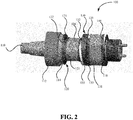
- FIG. 2 illustrates a cam shaft 110 with various spacers engaged with the cam shaft 110 according to various embodiments.
- the modified cam shaft system 100 may comprise a cam shaft 110, which may include cam shaft lobes 116 and 118, bearing holder 112, and cam journal 114.
- FIG. 2 illustrates a cam shaft 110 with three spacers (spacers 120, 130, and 140) according to various embodiments.
- the spacers disclosed herein may include a first face (e.g., 121 or 131) configured to engage with a cam shaft 110, a second face (e.g., 122 or 132), and a third face (e.g., 123 or 133) operationally coupled to the first face (e.g., 121 or 131) and the second face (e.g., 122 or 132), wherein the third face (e.g., 123 or 133) is configured to displace a motor oil and permit rotation of the cam shaft 110.
- the term operationally coupled may include any configuration where the third face is operationally linked or joined with the first and second face while allowing for the displacement of a lubricating fluid while the cam shaft rotates.
- spacers 120 and 130 have a first face (121 and 131) and a second face (122 and 132) respectively.
- Spacers 120 and 130 also include a third face (123 and 133 respectively) connected to the first face (121 and 131 respectively) and the second face (122 and 132 respectively).
- the third face (123 and 133 respectively) may be structured with the first face (121 and 131 respectively) and the second face (122 and 132 respectively), to form a volume around the cam shaft 110 and, thus, displace a lubricating fluid while allowing for rotation of the cam shaft 110 during operation of the fuel pump.
- FIG. 3 illustrates a portion of fuel pump 300 with plungers 316 and 318 and timing sprocket 312.
- spacers 120, 130, and 140 allow for lobes 116 and 118 to rotate while engaged with plungers 316 and 318 respectively.
- the volume of the spacers engaged with (e.g., coupled to) to the cam shaft 110 may displace reservoirs of lubricating liquid that would otherwise fill voids present in the absence of the spacers. Because the spacers displace significant amounts of lubricating fluid present in these voids, cam shafts with spacers will experience a significant reduction in parasitic power loss due to movement of lubricating liquid in proximity to the cam shaft.
- the spacers may be used with a variety of cam shafts, such as cam shafts used in fuel pumps to help displace oil and reduce oil windage and, thus, reduce parasitic power loss.
- the locations of the spacers are not particularly limited and may include oil located between two lobes 116, 118 of the cam shaft 110, for example as shown with spacer 130.
- FIG. 4 illustrates a cross-sectional side view of a camshaft 110 with spacers 120, 130 and 140
- FIG. 5 illustrates a cross-sectional top view of a camshaft with spacers 120, 130, and 140.
- spacers 120, 130, and 140 may axially displace a lubricating fluid.
- the third face (e.g., 123 and 133 shown in FIG. 2 ) may be shaped to affect the displaced oil according to various applications.
- spacers may comprise a fluid passageway, such as fluid passageway 135.
- fluid passageway 135 can serve to transport lubricating fluid from one end of the fuel pump to another area.
- the fluid passageway 135 can help alieve fluid pressure buildup in various portions along the cam shaft 110 and aid in dissipating heat.
- the spacer is not particularly limited and may include various metals, alloys, plastics, and combinations thereof.
- Exemplary metals include aluminum, titanium, steel, alloys thereof, or combinations thereof.
- Various exemplary plastics include thermoplastics and thermosets.
- Exemplary thermoplastics include polyether ether ketones (PEEK), Polyetherketones (PEK), nylons (e.g., poly[imino(1,6-dioxohexamethylene) iminohexamethylene] or Nylon 66), or combinations thereof.
- the configuration of the spacer for securing the spacer to the cam shaft 110 is not particularly limited and may include any known configuration or means for securing a spacer to a cam shaft 110.
- the spacer may be configured to be axially secured to the cam shaft, radially secured to the cam shaft, or combinations thereof.
- Exemplary methods, configurations, and means for securing the spacer to a cam shaft include bonding, welding, brazing, or soldering the spacer to the cam shaft, by placing a spacer pin into a spacer pin port of the cam shaft, by disposing a band circumferentially around a portion of the spacer and securing the band, or combinations thereof.
- FIG. 6 illustrates a spacer cam shaft system 600 according to various embodiments.
- Spacer cam shaft system 600 may include a spacer 130 with fluid passageway 135 engaged with cam shaft 110.
- spacer 130 may be secured to cam shaft 110 with a band 610, such as a boot band, configured to engage with a third face of spacer 130 to secure the spacer to the cam shaft.
- band 610 includes locking tabs 615.
- Spacer 700 includes a first face 710, a second face 720, a third face 730 connected to the first face 710 and the second face 720, wherein the third face 730 is configured to displace a motor oil and permit rotation of the cam shaft.
- spacer 700 may comprise at least one pin 750 engaged with the first face 710.
- pin 750 may be configured to enter a spacer pin port (not shown) of the cam shaft to help secure spacer 700 to a cam shaft.
- spacer 700 may also comprise a fourth face 740 connected to the first face 710 and the second face 720, wherein the fourth face 740 is configured to engage with a radial portion of the cam shaft 110.
- FIG. 8 illustrates a spacer 800 having a lip configured to engage with a lobe of the cam shaft.
- Spacer 800 includes a first face 810, a second face 820, a third face 830 connected to the first face 810 and the second face 820, wherein the third face 830 is configured to displace a motor oil and permit rotation of the cam shaft.
- spacer 800 may comprise a lip 815 engaged with the first face.
- lip 815 may comprise a first lip surface 816 and a second lip surface 817, which may help to engage the spacer to a lobe of the cam shaft 110 and allow for rotation of the cam shaft 110 when the pump is operating (e.g., while maintaining desired tappet clearances).
- a fourth face 840 may be connected to the first face 810 and the second face 810, wherein the fourth face 840 is configured to engage with a radial portion of the cam shaft 110.
- spacers may include a first face (e.g., 810), a second face (e.g., 820), a third face (e.g., 830) operationally coupled to the first face (e.g., 810) and the second face (e.g., 820), means for securing the spacer (e.g., 800) to a cam shaft 110, and means for permitting rotation of the cam shaft 110 while allowing for displacement of a fluid in contact with the cam shaft 110.
- a first face e.g., 810
- second face e.g., 820
- a third face e.g., 830
- references to "one embodiment,” “an embodiment,” “an example embodiment,” etc. indicate that the embodiment described may include a particular feature, structure, or characteristic, but every embodiment may not necessarily include the particular feature, structure, or characteristic. Moreover, such phrases are not necessarily referring to the same embodiment. Further, when a particular feature, structure, or characteristic is described in connection with an embodiment, it is submitted that it is within the knowledge of one skilled in the art with the benefit of the present disclosure to affect such feature, structure, or characteristic in connection with other embodiments whether or not explicitly described. After reading the description, it will be apparent to one skilled in the relevant art(s) how to implement the disclosure in alternative embodiments.
Landscapes
- Engineering & Computer Science (AREA)
- General Engineering & Computer Science (AREA)
- Mechanical Engineering (AREA)
- Reciprocating Pumps (AREA)
- Fuel-Injection Apparatus (AREA)
- Details Of Reciprocating Pumps (AREA)
Abstract
Description
- This disclosure relates to systems and methods for reducing oil volume and windage in fuel pumps. More specifically, this disclosure relates to spacers for reducing oil volume and windage in fuel pumps.
- Fuel pumps, such as those used in high pressure common rail systems, typically use a fluid, such as oil or fuel for lubrication. Many conventional fuel pumps use cam shafts to drive pistons to provide pressure to the fuel system (e.g., high pressure fuel rails).
- Many of the conventional fuel pumps have various voids between the cam shaft and the pump housing (e.g., the cam shaft lobes). In many instances, the voids may contain oil used to lubricate the moving parts of the fuel pump and aid in heat dissipation.
- Often, the volume of lubricating fluid may cause additional work to be performed because the oil may begin to move due to proximity to the cam shaft, which may be rotating. The rotation or movement of the lubricating fluid, or windage, may increase the amount of work required for the fuel pump and, thus, is a source of parasitic power loss in many conventional fuel systems.
- A need therefore exists to address issues of reducing the oil volume and windage in conventional and future fuel systems.
- In some embodiments, spacers may include a first face configured to engage with a cam shaft, a second face, and a third face operationally coupled to the first face and the second face, wherein the third face is configured to displace a lubricating fluid and permit rotation of the cam shaft.
- In various embodiments, methods of manufacture may include disposing a lubricating fluid displacer circumferentially around a portion of a cam shaft, and securing a spacer to the cam shaft.
- Also disclose are various embodiments of spacers including a first face, a second face, a third face operationally coupled to the first face and the second face, means for securing the spacer to a cam shaft, and means for permitting rotation of the cam shaft while allowing for displacement of a fluid in contact with the cam shaft.
- An aspect of the present invention provides a spacer comprising: a first face configured to engage with a cam shaft; a second face; and a third face operationally coupled to the first face and the second face, wherein the third face is configured to displace a lubricating fluid and permit rotation of the cam shaft.
- The spacer may be configured to displace a lubricating fluid between two lobes of the cam shaft. The spacer may further comprise a pin coupled to the first face to engage the cam shaft. The first face may comprise a lip to engage a lobe of the cam shaft. The spacer may further comprise a fluid passageway. The spacer may further comprise a fourth face connected to the first face and the second face, wherein the fourth face is configured to engage with a radial portion of the cam shaft. The spacer may be configured to be axially secured to the cam shaft. The spacer may be configured to be radially secured to the cam shaft. The spacer may further comprise a boot band and locking tabs, wherein the boot band is configured to engage with the third face to secure the spacer to the cam shaft. The spacer may be bonded to the cam shaft. The spacer may comprise a plastic, which may comprise one of polyether ether ketones (PEEK), Polyetherketones (PEK), Poly[imino(1,6-dioxohexamethylene) iminohexamethylene], and combinations thereof.
- Another aspect of the present invention provides a fuel pump comprising the spacer according to the above-defined aspect of the present invention.
- Another aspect of the present invention provides a method of manufacture comprising: disposing a lubricating fluid displacer circumferentially around a portion of a cam shaft; and securing a spacer to the cam shaft, wherein the fluid displacer comprises a first face configured to engage with a cam shaft; a second face; and a third face operationally coupled to the first face and the second face, wherein the third face is configured to displace a lubricating fluid and permit rotation of the cam shaft.
- In the method, securing the spacer may comprise disposing a band circumferentially around a portion of the spacer and securing the band. Securing the spacer may comprise bonding the spacer to the cam shaft. The spacer may comprise a plastic. The method may further comprise placing a spacer pin into a spacer pin port of the cam shaft.
- A further aspect of the present invention provides a spacer comprising: a first face; a second face; a third face operationally coupled to the first face and the second face; means for securing the spacer to a cam shaft; and means for permitting rotation of the cam shaft while allowing for displacement of a fluid in contact with the cam shaft.
- The spacer may be a plastic, which may comprise one of polyether ether ketones (PEEK), Polyetherketones (PEK), Poly[imino(1,6-dioxohexamethylene) iminohexamethylene], and combinations thereof. The spacer may further comprise a fluid passageway.
- The above mentioned and other features and objects of this disclosure, and the manner of attaining them, will become more apparent and the disclosure itself will be better understood by reference to the following description of an embodiment of the disclosure taken in conjunction with the accompanying drawings, wherein:
-
FIG. 1 illustrates a method of manufacturing a camshaft with spacers according to various embodiments; -
FIG. 2 is a perspective view of a cam shaft with a spacer according to various embodiments; -
FIG. 3 is a side view of a fuel pump with a spacer according to various embodiments; -
FIG. 4 is cross-sectional view of a fuel pump with a spacer according to various embodiments; -
FIG. 5 is another cross-sectional view of a fuel pump with a spacer according to various embodiments; -
FIG. 6 is a perspective view of a spacer engaged with a cam shaft with a band and locking tab according to various embodiments; -
FIG. 7 is a perspective view of a spacer with a pin according to various embodiments; and -
FIG. 8 is a perspective view of a spacer with a cam lobe according to various embodiments. - Corresponding reference characters indicate corresponding parts throughout the several views. Although the drawings represent embodiments of the present disclosure, the drawings are not necessarily to scale and certain features may be exaggerated in order to better illustrate and explain the present disclosure. The exemplifications set out herein illustrate embodiments of the disclosure, in one form, and such exemplifications are not to be construed as limiting the scope of the disclosure in any manner.
- The embodiments disclosed herein are not intended to be exhaustive or limit the disclosure to the precise form disclosed in the following detailed description. Rather, the embodiments are chosen and described so that others skilled in the art may utilize the teachings of the present disclosure.
-
FIG. 1 illustrates a method of manufacturing a cam shaft (such ascam shaft 110 inFIG. 2 ) with spacers according to various embodiments. As shown inFIG. 1 ,method 10 may comprise disposing an oil displacer circumferentially around a portion of a cam shaft (step 11) and securing a spacer to the cam shaft (step 12). -
Method 10 is not particularly limited and may include any method capable of securing the spacer to the cam shaft. For example, the securing of the spacer may be accomplished by bonding the spacer to the cam shaft, by placing a spacer pin into a spacer pin port of the cam shaft, by disposing a band circumferentially around a portion of the spacer and securing the band, or combinations thereof. - Moreover,
method 10 may include any of the spacers disclosed herein, such as those comprised of a plastic, such as the spacer illustrated inFIG. 6 and discussed in further detail herein. -
FIG. 2 illustrates acam shaft 110 with various spacers engaged with thecam shaft 110 according to various embodiments. The modifiedcam shaft system 100 may comprise acam shaft 110, which may includecam shaft lobes bearing holder 112, andcam journal 114.FIG. 2 illustrates acam shaft 110 with three spacers (spacers cam shaft 110, a second face (e.g., 122 or 132), and a third face (e.g., 123 or 133) operationally coupled to the first face (e.g., 121 or 131) and the second face (e.g., 122 or 132), wherein the third face (e.g., 123 or 133) is configured to displace a motor oil and permit rotation of thecam shaft 110. As used herein, the term operationally coupled may include any configuration where the third face is operationally linked or joined with the first and second face while allowing for the displacement of a lubricating fluid while the cam shaft rotates. - For example,
spacers Spacers cam shaft 110 and, thus, displace a lubricating fluid while allowing for rotation of thecam shaft 110 during operation of the fuel pump. - For example,
FIG. 3 illustrates a portion offuel pump 300 withplungers timing sprocket 312. As can be seen inFIG. 3 ,spacers lobes plungers - In other words, the volume of the spacers engaged with (e.g., coupled to) to the
cam shaft 110 may displace reservoirs of lubricating liquid that would otherwise fill voids present in the absence of the spacers. Because the spacers displace significant amounts of lubricating fluid present in these voids, cam shafts with spacers will experience a significant reduction in parasitic power loss due to movement of lubricating liquid in proximity to the cam shaft. - The spacers may be used with a variety of cam shafts, such as cam shafts used in fuel pumps to help displace oil and reduce oil windage and, thus, reduce parasitic power loss. The locations of the spacers are not particularly limited and may include oil located between two
lobes cam shaft 110, for example as shown withspacer 130. - For example, with reference to
FIGs. 4 and5 ,FIG. 4 illustrates a cross-sectional side view of acamshaft 110 withspacers FIG. 5 illustrates a cross-sectional top view of a camshaft withspacers FIGs. 4 and5 ,spacers - Moreover, in various embodiments, the third face (e.g., 123 and 133 shown in
FIG. 2 ) may be shaped to affect the displaced oil according to various applications. For example, in some embodiments, spacers may comprise a fluid passageway, such asfluid passageway 135. In various embodiments,fluid passageway 135 can serve to transport lubricating fluid from one end of the fuel pump to another area. Moreover, in various embodiments, thefluid passageway 135 can help alieve fluid pressure buildup in various portions along thecam shaft 110 and aid in dissipating heat. - The spacer is not particularly limited and may include various metals, alloys, plastics, and combinations thereof. Exemplary metals include aluminum, titanium, steel, alloys thereof, or combinations thereof. Various exemplary plastics include thermoplastics and thermosets. Exemplary thermoplastics include polyether ether ketones (PEEK), Polyetherketones (PEK), nylons (e.g., poly[imino(1,6-dioxohexamethylene) iminohexamethylene] or Nylon 66), or combinations thereof.
- The configuration of the spacer for securing the spacer to the
cam shaft 110 is not particularly limited and may include any known configuration or means for securing a spacer to acam shaft 110. Thus, the spacer may be configured to be axially secured to the cam shaft, radially secured to the cam shaft, or combinations thereof. Exemplary methods, configurations, and means for securing the spacer to a cam shaft include bonding, welding, brazing, or soldering the spacer to the cam shaft, by placing a spacer pin into a spacer pin port of the cam shaft, by disposing a band circumferentially around a portion of the spacer and securing the band, or combinations thereof. - For example,
FIG. 6 illustrates a spacercam shaft system 600 according to various embodiments. Spacercam shaft system 600 may include aspacer 130 withfluid passageway 135 engaged withcam shaft 110. In various embodiments,spacer 130 may be secured tocam shaft 110 with aband 610, such as a boot band, configured to engage with a third face ofspacer 130 to secure the spacer to the cam shaft. In various embodiments,band 610 includes locking tabs 615. - With reference to
FIG. 7 , a spacer comprising a spacer pin is illustrated.Spacer 700 includes afirst face 710, asecond face 720, athird face 730 connected to thefirst face 710 and thesecond face 720, wherein thethird face 730 is configured to displace a motor oil and permit rotation of the cam shaft. Moreover,spacer 700 may comprise at least onepin 750 engaged with thefirst face 710. In various embodiments, pin 750 may be configured to enter a spacer pin port (not shown) of the cam shaft to helpsecure spacer 700 to a cam shaft. In various embodiments,spacer 700 may also comprise afourth face 740 connected to thefirst face 710 and thesecond face 720, wherein thefourth face 740 is configured to engage with a radial portion of thecam shaft 110. - As yet another example,
FIG. 8 illustrates aspacer 800 having a lip configured to engage with a lobe of the cam shaft.Spacer 800 includes afirst face 810, asecond face 820, athird face 830 connected to thefirst face 810 and thesecond face 820, wherein thethird face 830 is configured to displace a motor oil and permit rotation of the cam shaft. Additionally,spacer 800 may comprise alip 815 engaged with the first face. In various embodiments,lip 815 may comprise afirst lip surface 816 and asecond lip surface 817, which may help to engage the spacer to a lobe of thecam shaft 110 and allow for rotation of thecam shaft 110 when the pump is operating (e.g., while maintaining desired tappet clearances). Also, in some embodiments, afourth face 840 may be connected to thefirst face 810 and thesecond face 810, wherein thefourth face 840 is configured to engage with a radial portion of thecam shaft 110. - Thus, spacers according to various embodiments may include a first face (e.g., 810), a second face (e.g., 820), a third face (e.g., 830) operationally coupled to the first face (e.g., 810) and the second face (e.g., 820), means for securing the spacer (e.g., 800) to a
cam shaft 110, and means for permitting rotation of thecam shaft 110 while allowing for displacement of a fluid in contact with thecam shaft 110. - While this disclosure has been described as having various exemplary designs, the present disclosure may be further modified within the spirit and scope of this disclosure. This application is therefore intended to cover any variations, uses, or adaptations of the disclosure using its general principles. Further, this application is intended to cover such departures from the present disclosure as come within known or customary practice in the art to which this disclosure pertains.
- Furthermore, the connecting lines shown in the various figures contained herein are intended to represent exemplary functional relationships and/or physical couplings between the various elements. It should be noted that many alternative or additional functional relationships or physical connections may be present in a practical system. However, the benefits, advantages, solutions to problems, and any elements that may cause any benefit, advantage, or solution to occur or become more pronounced are not to be construed as critical, required, or essential features or elements. The scope is accordingly to be limited by nothing other than the appended claims, in which reference to an element in the singular is not intended to mean "one and only one" unless explicitly so stated, but rather "one or more." Moreover, where a phrase similar to "at least one of A, B, or C" is used in the claims, it is intended that the phrase be interpreted to mean that A alone may be present in an embodiment, B alone may be present in an embodiment, C alone may be present in an embodiment, or that any combination of the elements A, B or C may be present in a single embodiment; for example, A and B, A and C, B and C, or A and B and C.
- In the detailed description herein, references to "one embodiment," "an embodiment," "an example embodiment," etc., indicate that the embodiment described may include a particular feature, structure, or characteristic, but every embodiment may not necessarily include the particular feature, structure, or characteristic. Moreover, such phrases are not necessarily referring to the same embodiment. Further, when a particular feature, structure, or characteristic is described in connection with an embodiment, it is submitted that it is within the knowledge of one skilled in the art with the benefit of the present disclosure to affect such feature, structure, or characteristic in connection with other embodiments whether or not explicitly described. After reading the description, it will be apparent to one skilled in the relevant art(s) how to implement the disclosure in alternative embodiments.
- Furthermore, no element, component, or method step in the present disclosure is intended to be dedicated to the public regardless of whether the element, component, or method step is explicitly recited in the claims. No claim element herein is to be construed under the provisions of 35 U.S.C. § 112(f), unless the element is expressly recited using the phrase "means for." As used herein, the terms "comprises," "comprising," or any other variation thereof, are intended to cover a non-exclusive inclusion, such that a process, method, article, or apparatus that comprises a list of elements does not include only those elements but may include other elements not expressly listed or inherent to such process, method, article, or apparatus.
Claims (17)
- A spacer comprising:a first face configured to engage with a cam shaft;a second face; anda third face operationally coupled to the first face and the second face, wherein the third face is configured to displace a lubricating fluid and permit rotation of the cam shaft.
- The spacer of claim 1, wherein the spacer is configured to displace a lubricating fluid between two lobes of the cam shaft.
- The spacer of claim 1 or 2, further comprising a pin coupled to the first face to engage the cam shaft.
- The spacer of claim 1, 2 or 3, wherein the first face comprises a lip to engage a lobe of the cam shaft.
- The spacer of any preceding claim, further comprising: (i) a fluid passageway and/or (ii) a fourth face connected to the first face and the second face, wherein the fourth face is configured to engage with a radial portion of the cam shaft.
- The spacer of any preceding claim, wherein the spacer is configured to be axially secured to the cam shaft and/or radially secured to the cam shaft.
- The spacer of any preceding claim, further comprising a boot band and locking tabs, wherein the boot band is configured to engage with the third face to secure the spacer to the cam shaft.
- The spacer of any preceding claim, wherein the spacer is bonded to the cam shaft.
- The spacer of any preceding claim, wherein the spacer comprises a plastic, optionally wherein the plastic comprises one of polyether ether ketones (PEEK), Polyetherketones (PEK), Poly[imino(1,6-dioxohexamethylene) iminohexamethylene], and combinations thereof.
- A fuel pump comprising the spacer of any preceding claim.
- A method of manufacture comprising:disposing a lubricating fluid displacer circumferentially around a portion of a cam shaft; andsecuring a spacer to the cam shaft, wherein the fluid displacer comprisesa first face configured to engage with a cam shaft;a second face; anda third face operationally coupled to the first face and the second face, wherein the third face is configured to displace a lubricating fluid and permit rotation of the cam shaft.
- The method according to claim 11, wherein securing the spacer comprises (i) disposing a band circumferentially around a portion of the spacer and securing the band and/or (ii) bonding the spacer to the cam shaft.
- The method according to claim 11 or 12, wherein the spacer comprises a plastic.
- The method according to claim 11, 12 or 13, further comprising placing a spacer pin into a spacer pin port of the cam shaft.
- A spacer comprising:a first face;a second face;a third face operationally coupled to the first face and the second face;means for securing the spacer to a cam shaft; andmeans for permitting rotation of the cam shaft while allowing for displacement of a fluid in contact with the cam shaft.
- The spacer of claim 15, wherein the spacer is a plastic, optionally wherein the plastic comprises one of polyether ether ketones (PEEK), Polyetherketones (PEK), Poly[imino(1,6-dioxohexamethylene) iminohexamethylene], and combinations thereof.
- The spacer of claim 15 or 16, further comprising a fluid passageway.
Applications Claiming Priority (1)
| Application Number | Priority Date | Filing Date | Title |
|---|---|---|---|
| US15/057,659 US10677119B2 (en) | 2016-03-01 | 2016-03-01 | Systems and methods for reducing the oil volume and windage in fuel pumps |
Publications (2)
| Publication Number | Publication Date |
|---|---|
| EP3214306A1 true EP3214306A1 (en) | 2017-09-06 |
| EP3214306B1 EP3214306B1 (en) | 2024-06-12 |
Family
ID=58231416
Family Applications (1)
| Application Number | Title | Priority Date | Filing Date |
|---|---|---|---|
| EP17158674.6A Active EP3214306B1 (en) | 2016-03-01 | 2017-03-01 | Systems and methods for reducing the oil volume and windage in fuel pumps |
Country Status (2)
| Country | Link |
|---|---|
| US (1) | US10677119B2 (en) |
| EP (1) | EP3214306B1 (en) |
Cited By (1)
| Publication number | Priority date | Publication date | Assignee | Title |
|---|---|---|---|---|
| WO2018108843A1 (en) * | 2016-12-13 | 2018-06-21 | Delphi Technologies Ip Limited | Cam actuated fuel pump |
Citations (9)
| Publication number | Priority date | Publication date | Assignee | Title |
|---|---|---|---|---|
| JPH0821211A (en) * | 1994-06-30 | 1996-01-23 | Nippon Seiko Kk | Camshaft for engine |
| US6591713B2 (en) * | 2000-08-18 | 2003-07-15 | Jesel, Inc. | Modular camshaft assembly |
| EP1544462A2 (en) * | 2003-12-15 | 2005-06-22 | Denso Corporation | Fuel supply pump having lubricating groove |
| WO2010046952A1 (en) * | 2008-10-24 | 2010-04-29 | パスカルエンジニアリング株式会社 | Hydraulic pressure generation device |
| US8083504B2 (en) * | 2007-10-05 | 2011-12-27 | Weatherford/Lamb, Inc. | Quintuplex mud pump |
| CN203271978U (en) * | 2013-03-04 | 2013-11-06 | 罗伯特·博世有限公司 | Plunger type oil supplying pump and diesel engine with same |
| DE102012219537A1 (en) * | 2012-10-25 | 2014-04-30 | Robert Bosch Gmbh | High-pressure fuel pump with a bearing supply via lubrication holes in a drive shaft |
| DE102013212047A1 (en) * | 2013-06-25 | 2015-01-08 | Robert Bosch Gmbh | Pump device, in particular high-pressure fuel pump device for a fuel injection device |
| US20150361976A1 (en) * | 2015-08-25 | 2015-12-17 | Chien Fu Lai | Output shaft lubricating structure of liquid pressurizing pump |
Family Cites Families (7)
| Publication number | Priority date | Publication date | Assignee | Title |
|---|---|---|---|---|
| US192567A (en) * | 1877-07-03 | Thomas a | ||
| GB8927639D0 (en) * | 1989-12-07 | 1990-02-07 | Rubery Owen Rockwell Ltd | Bearing assemblies |
| US5479886A (en) | 1995-05-12 | 1996-01-02 | Cummins Engine | Engine oil capacitor |
| US20060102132A1 (en) | 2004-11-18 | 2006-05-18 | Johnson Kevin L | Close tolerance crankshaft oil scraper |
| DE102008060412B4 (en) | 2008-11-28 | 2023-03-30 | Dr. Ing. H.C. F. Porsche Aktiengesellschaft | combustion engine |
| DE102010055189B4 (en) | 2010-12-20 | 2023-11-09 | Volkswagen Aktiengesellschaft | Oil plane and combustion engine with oil plane |
| DE102012220210A1 (en) * | 2012-11-07 | 2014-05-08 | Schaeffler Technologies Gmbh & Co. Kg | Camshaft of a variable-displacement gas exchange valve train |
-
2016
- 2016-03-01 US US15/057,659 patent/US10677119B2/en active Active
-
2017
- 2017-03-01 EP EP17158674.6A patent/EP3214306B1/en active Active
Patent Citations (9)
| Publication number | Priority date | Publication date | Assignee | Title |
|---|---|---|---|---|
| JPH0821211A (en) * | 1994-06-30 | 1996-01-23 | Nippon Seiko Kk | Camshaft for engine |
| US6591713B2 (en) * | 2000-08-18 | 2003-07-15 | Jesel, Inc. | Modular camshaft assembly |
| EP1544462A2 (en) * | 2003-12-15 | 2005-06-22 | Denso Corporation | Fuel supply pump having lubricating groove |
| US8083504B2 (en) * | 2007-10-05 | 2011-12-27 | Weatherford/Lamb, Inc. | Quintuplex mud pump |
| WO2010046952A1 (en) * | 2008-10-24 | 2010-04-29 | パスカルエンジニアリング株式会社 | Hydraulic pressure generation device |
| DE102012219537A1 (en) * | 2012-10-25 | 2014-04-30 | Robert Bosch Gmbh | High-pressure fuel pump with a bearing supply via lubrication holes in a drive shaft |
| CN203271978U (en) * | 2013-03-04 | 2013-11-06 | 罗伯特·博世有限公司 | Plunger type oil supplying pump and diesel engine with same |
| DE102013212047A1 (en) * | 2013-06-25 | 2015-01-08 | Robert Bosch Gmbh | Pump device, in particular high-pressure fuel pump device for a fuel injection device |
| US20150361976A1 (en) * | 2015-08-25 | 2015-12-17 | Chien Fu Lai | Output shaft lubricating structure of liquid pressurizing pump |
Cited By (1)
| Publication number | Priority date | Publication date | Assignee | Title |
|---|---|---|---|---|
| WO2018108843A1 (en) * | 2016-12-13 | 2018-06-21 | Delphi Technologies Ip Limited | Cam actuated fuel pump |
Also Published As
| Publication number | Publication date |
|---|---|
| US20170254237A1 (en) | 2017-09-07 |
| EP3214306B1 (en) | 2024-06-12 |
| US10677119B2 (en) | 2020-06-09 |
Similar Documents
| Publication | Publication Date | Title |
|---|---|---|
| US10458414B2 (en) | Automotive electric liquid pump | |
| CN105298837A (en) | Electric pump unit | |
| US10844759B2 (en) | Variable speed cooling compressor including lubricating oil pumping system | |
| EP1286055B1 (en) | Wet rotor pump | |
| EP2809944A2 (en) | Pump head for a fuel pump | |
| CN106989009B (en) | positive displacement pump | |
| CN204572453U (en) | Motor-drive pump | |
| US10677119B2 (en) | Systems and methods for reducing the oil volume and windage in fuel pumps | |
| CN107532556B (en) | Tappet roller retention scheme | |
| US20130336765A1 (en) | Crankshaft for an alternative cooling compressor | |
| JP2025506647A (en) | Rotating seal follow-up improvement device | |
| US20150198064A1 (en) | Hydrostatic thrust bearing | |
| US9982672B2 (en) | Fuel pump | |
| EP3234417B1 (en) | Bearing isolator seal with enhanced rotor drive coupling | |
| CN204572296U (en) | Oil feed pump and there is the diesel engine of this oil feed pump | |
| JP5812020B2 (en) | Fuel supply pump | |
| JP2003065439A (en) | High pressure fluid sealing device | |
| EP3599379B1 (en) | High efficiency gear pump bearing assembly | |
| JP4840348B2 (en) | pump | |
| US10054162B2 (en) | Sliding bearing | |
| CN114623077A (en) | bead liner | |
| US20200340474A1 (en) | Vane cell pump comprising a pressure equalization connection | |
| JP2010174851A (en) | Shaft-rotor assembly for compressor, vane rotary compressor, and method for manufacturing the shaft-rotor assembly for compressor | |
| EP2587058A1 (en) | Bent axis type hydraulic rotating machine | |
| KR102294083B1 (en) | Roll of Rolling Mill Including Different Kind Metal Junctional Body Component |
Legal Events
| Date | Code | Title | Description |
|---|---|---|---|
| PUAI | Public reference made under article 153(3) epc to a published international application that has entered the european phase |
Free format text: ORIGINAL CODE: 0009012 |
|
| STAA | Information on the status of an ep patent application or granted ep patent |
Free format text: STATUS: THE APPLICATION HAS BEEN PUBLISHED |
|
| AK | Designated contracting states |
Kind code of ref document: A1 Designated state(s): AL AT BE BG CH CY CZ DE DK EE ES FI FR GB GR HR HU IE IS IT LI LT LU LV MC MK MT NL NO PL PT RO RS SE SI SK SM TR |
|
| AX | Request for extension of the european patent |
Extension state: BA ME |
|
| STAA | Information on the status of an ep patent application or granted ep patent |
Free format text: STATUS: REQUEST FOR EXAMINATION WAS MADE |
|
| 17P | Request for examination filed |
Effective date: 20180302 |
|
| RBV | Designated contracting states (corrected) |
Designated state(s): AL AT BE BG CH CY CZ DE DK EE ES FI FR GB GR HR HU IE IS IT LI LT LU LV MC MK MT NL NO PL PT RO RS SE SI SK SM TR |
|
| STAA | Information on the status of an ep patent application or granted ep patent |
Free format text: STATUS: EXAMINATION IS IN PROGRESS |
|
| 17Q | First examination report despatched |
Effective date: 20200831 |
|
| P01 | Opt-out of the competence of the unified patent court (upc) registered |
Effective date: 20230510 |
|
| GRAP | Despatch of communication of intention to grant a patent |
Free format text: ORIGINAL CODE: EPIDOSNIGR1 |
|
| STAA | Information on the status of an ep patent application or granted ep patent |
Free format text: STATUS: GRANT OF PATENT IS INTENDED |
|
| INTG | Intention to grant announced |
Effective date: 20240108 |
|
| GRAS | Grant fee paid |
Free format text: ORIGINAL CODE: EPIDOSNIGR3 |
|
| GRAA | (expected) grant |
Free format text: ORIGINAL CODE: 0009210 |
|
| STAA | Information on the status of an ep patent application or granted ep patent |
Free format text: STATUS: THE PATENT HAS BEEN GRANTED |
|
| AK | Designated contracting states |
Kind code of ref document: B1 Designated state(s): AL AT BE BG CH CY CZ DE DK EE ES FI FR GB GR HR HU IE IS IT LI LT LU LV MC MK MT NL NO PL PT RO RS SE SI SK SM TR |
|
| REG | Reference to a national code |
Ref country code: GB Ref legal event code: FG4D |
|
| REG | Reference to a national code |
Ref country code: CH Ref legal event code: EP |
|
| REG | Reference to a national code |
Ref country code: DE Ref legal event code: R096 Ref document number: 602017082505 Country of ref document: DE |
|
| REG | Reference to a national code |
Ref country code: IE Ref legal event code: FG4D |
|
| PG25 | Lapsed in a contracting state [announced via postgrant information from national office to epo] |
Ref country code: BG Free format text: LAPSE BECAUSE OF FAILURE TO SUBMIT A TRANSLATION OF THE DESCRIPTION OR TO PAY THE FEE WITHIN THE PRESCRIBED TIME-LIMIT Effective date: 20240612 |
|
| PG25 | Lapsed in a contracting state [announced via postgrant information from national office to epo] |
Ref country code: HR Free format text: LAPSE BECAUSE OF FAILURE TO SUBMIT A TRANSLATION OF THE DESCRIPTION OR TO PAY THE FEE WITHIN THE PRESCRIBED TIME-LIMIT Effective date: 20240612 Ref country code: FI Free format text: LAPSE BECAUSE OF FAILURE TO SUBMIT A TRANSLATION OF THE DESCRIPTION OR TO PAY THE FEE WITHIN THE PRESCRIBED TIME-LIMIT Effective date: 20240612 |
|
| REG | Reference to a national code |
Ref country code: LT Ref legal event code: MG9D |
|
| PG25 | Lapsed in a contracting state [announced via postgrant information from national office to epo] |
Ref country code: GR Free format text: LAPSE BECAUSE OF FAILURE TO SUBMIT A TRANSLATION OF THE DESCRIPTION OR TO PAY THE FEE WITHIN THE PRESCRIBED TIME-LIMIT Effective date: 20240913 |
|
| REG | Reference to a national code |
Ref country code: NL Ref legal event code: MP Effective date: 20240612 |
|
| PG25 | Lapsed in a contracting state [announced via postgrant information from national office to epo] |
Ref country code: ES Free format text: LAPSE BECAUSE OF FAILURE TO SUBMIT A TRANSLATION OF THE DESCRIPTION OR TO PAY THE FEE WITHIN THE PRESCRIBED TIME-LIMIT Effective date: 20240612 |
|
| PG25 | Lapsed in a contracting state [announced via postgrant information from national office to epo] |
Ref country code: LV Free format text: LAPSE BECAUSE OF FAILURE TO SUBMIT A TRANSLATION OF THE DESCRIPTION OR TO PAY THE FEE WITHIN THE PRESCRIBED TIME-LIMIT Effective date: 20240612 |
|
| PG25 | Lapsed in a contracting state [announced via postgrant information from national office to epo] |
Ref country code: NO Free format text: LAPSE BECAUSE OF FAILURE TO SUBMIT A TRANSLATION OF THE DESCRIPTION OR TO PAY THE FEE WITHIN THE PRESCRIBED TIME-LIMIT Effective date: 20240912 Ref country code: LV Free format text: LAPSE BECAUSE OF FAILURE TO SUBMIT A TRANSLATION OF THE DESCRIPTION OR TO PAY THE FEE WITHIN THE PRESCRIBED TIME-LIMIT Effective date: 20240612 Ref country code: HR Free format text: LAPSE BECAUSE OF FAILURE TO SUBMIT A TRANSLATION OF THE DESCRIPTION OR TO PAY THE FEE WITHIN THE PRESCRIBED TIME-LIMIT Effective date: 20240612 Ref country code: GR Free format text: LAPSE BECAUSE OF FAILURE TO SUBMIT A TRANSLATION OF THE DESCRIPTION OR TO PAY THE FEE WITHIN THE PRESCRIBED TIME-LIMIT Effective date: 20240913 Ref country code: FI Free format text: LAPSE BECAUSE OF FAILURE TO SUBMIT A TRANSLATION OF THE DESCRIPTION OR TO PAY THE FEE WITHIN THE PRESCRIBED TIME-LIMIT Effective date: 20240612 Ref country code: ES Free format text: LAPSE BECAUSE OF FAILURE TO SUBMIT A TRANSLATION OF THE DESCRIPTION OR TO PAY THE FEE WITHIN THE PRESCRIBED TIME-LIMIT Effective date: 20240612 Ref country code: BG Free format text: LAPSE BECAUSE OF FAILURE TO SUBMIT A TRANSLATION OF THE DESCRIPTION OR TO PAY THE FEE WITHIN THE PRESCRIBED TIME-LIMIT Effective date: 20240612 Ref country code: RS Free format text: LAPSE BECAUSE OF FAILURE TO SUBMIT A TRANSLATION OF THE DESCRIPTION OR TO PAY THE FEE WITHIN THE PRESCRIBED TIME-LIMIT Effective date: 20240912 |
|
| PG25 | Lapsed in a contracting state [announced via postgrant information from national office to epo] |
Ref country code: NL Free format text: LAPSE BECAUSE OF FAILURE TO SUBMIT A TRANSLATION OF THE DESCRIPTION OR TO PAY THE FEE WITHIN THE PRESCRIBED TIME-LIMIT Effective date: 20240612 |
|
| REG | Reference to a national code |
Ref country code: AT Ref legal event code: MK05 Ref document number: 1694469 Country of ref document: AT Kind code of ref document: T Effective date: 20240612 |
|
| PG25 | Lapsed in a contracting state [announced via postgrant information from national office to epo] |
Ref country code: NL Free format text: LAPSE BECAUSE OF FAILURE TO SUBMIT A TRANSLATION OF THE DESCRIPTION OR TO PAY THE FEE WITHIN THE PRESCRIBED TIME-LIMIT Effective date: 20240612 |
|
| PG25 | Lapsed in a contracting state [announced via postgrant information from national office to epo] |
Ref country code: PT Free format text: LAPSE BECAUSE OF FAILURE TO SUBMIT A TRANSLATION OF THE DESCRIPTION OR TO PAY THE FEE WITHIN THE PRESCRIBED TIME-LIMIT Effective date: 20241014 |
|
| PG25 | Lapsed in a contracting state [announced via postgrant information from national office to epo] |
Ref country code: PT Free format text: LAPSE BECAUSE OF FAILURE TO SUBMIT A TRANSLATION OF THE DESCRIPTION OR TO PAY THE FEE WITHIN THE PRESCRIBED TIME-LIMIT Effective date: 20241014 |
|
| PG25 | Lapsed in a contracting state [announced via postgrant information from national office to epo] |
Ref country code: PL Free format text: LAPSE BECAUSE OF FAILURE TO SUBMIT A TRANSLATION OF THE DESCRIPTION OR TO PAY THE FEE WITHIN THE PRESCRIBED TIME-LIMIT Effective date: 20240612 |
|
| PG25 | Lapsed in a contracting state [announced via postgrant information from national office to epo] |
Ref country code: EE Free format text: LAPSE BECAUSE OF FAILURE TO SUBMIT A TRANSLATION OF THE DESCRIPTION OR TO PAY THE FEE WITHIN THE PRESCRIBED TIME-LIMIT Effective date: 20240612 |
|
| PG25 | Lapsed in a contracting state [announced via postgrant information from national office to epo] |
Ref country code: IS Free format text: LAPSE BECAUSE OF FAILURE TO SUBMIT A TRANSLATION OF THE DESCRIPTION OR TO PAY THE FEE WITHIN THE PRESCRIBED TIME-LIMIT Effective date: 20241012 Ref country code: AT Free format text: LAPSE BECAUSE OF FAILURE TO SUBMIT A TRANSLATION OF THE DESCRIPTION OR TO PAY THE FEE WITHIN THE PRESCRIBED TIME-LIMIT Effective date: 20240612 |
|
| PG25 | Lapsed in a contracting state [announced via postgrant information from national office to epo] |
Ref country code: CZ Free format text: LAPSE BECAUSE OF FAILURE TO SUBMIT A TRANSLATION OF THE DESCRIPTION OR TO PAY THE FEE WITHIN THE PRESCRIBED TIME-LIMIT Effective date: 20240612 |
|
| PG25 | Lapsed in a contracting state [announced via postgrant information from national office to epo] |
Ref country code: RO Free format text: LAPSE BECAUSE OF FAILURE TO SUBMIT A TRANSLATION OF THE DESCRIPTION OR TO PAY THE FEE WITHIN THE PRESCRIBED TIME-LIMIT Effective date: 20240612 Ref country code: SK Free format text: LAPSE BECAUSE OF FAILURE TO SUBMIT A TRANSLATION OF THE DESCRIPTION OR TO PAY THE FEE WITHIN THE PRESCRIBED TIME-LIMIT Effective date: 20240612 |
|
| PG25 | Lapsed in a contracting state [announced via postgrant information from national office to epo] |
Ref country code: SM Free format text: LAPSE BECAUSE OF FAILURE TO SUBMIT A TRANSLATION OF THE DESCRIPTION OR TO PAY THE FEE WITHIN THE PRESCRIBED TIME-LIMIT Effective date: 20240612 |
|
| PG25 | Lapsed in a contracting state [announced via postgrant information from national office to epo] |
Ref country code: SM Free format text: LAPSE BECAUSE OF FAILURE TO SUBMIT A TRANSLATION OF THE DESCRIPTION OR TO PAY THE FEE WITHIN THE PRESCRIBED TIME-LIMIT Effective date: 20240612 Ref country code: SK Free format text: LAPSE BECAUSE OF FAILURE TO SUBMIT A TRANSLATION OF THE DESCRIPTION OR TO PAY THE FEE WITHIN THE PRESCRIBED TIME-LIMIT Effective date: 20240612 Ref country code: RO Free format text: LAPSE BECAUSE OF FAILURE TO SUBMIT A TRANSLATION OF THE DESCRIPTION OR TO PAY THE FEE WITHIN THE PRESCRIBED TIME-LIMIT Effective date: 20240612 Ref country code: PL Free format text: LAPSE BECAUSE OF FAILURE TO SUBMIT A TRANSLATION OF THE DESCRIPTION OR TO PAY THE FEE WITHIN THE PRESCRIBED TIME-LIMIT Effective date: 20240612 Ref country code: IS Free format text: LAPSE BECAUSE OF FAILURE TO SUBMIT A TRANSLATION OF THE DESCRIPTION OR TO PAY THE FEE WITHIN THE PRESCRIBED TIME-LIMIT Effective date: 20241012 Ref country code: EE Free format text: LAPSE BECAUSE OF FAILURE TO SUBMIT A TRANSLATION OF THE DESCRIPTION OR TO PAY THE FEE WITHIN THE PRESCRIBED TIME-LIMIT Effective date: 20240612 Ref country code: CZ Free format text: LAPSE BECAUSE OF FAILURE TO SUBMIT A TRANSLATION OF THE DESCRIPTION OR TO PAY THE FEE WITHIN THE PRESCRIBED TIME-LIMIT Effective date: 20240612 Ref country code: AT Free format text: LAPSE BECAUSE OF FAILURE TO SUBMIT A TRANSLATION OF THE DESCRIPTION OR TO PAY THE FEE WITHIN THE PRESCRIBED TIME-LIMIT Effective date: 20240612 |
|
| PG25 | Lapsed in a contracting state [announced via postgrant information from national office to epo] |
Ref country code: IT Free format text: LAPSE BECAUSE OF FAILURE TO SUBMIT A TRANSLATION OF THE DESCRIPTION OR TO PAY THE FEE WITHIN THE PRESCRIBED TIME-LIMIT Effective date: 20240612 |
|
| REG | Reference to a national code |
Ref country code: DE Ref legal event code: R097 Ref document number: 602017082505 Country of ref document: DE |
|
| PG25 | Lapsed in a contracting state [announced via postgrant information from national office to epo] |
Ref country code: DK Free format text: LAPSE BECAUSE OF FAILURE TO SUBMIT A TRANSLATION OF THE DESCRIPTION OR TO PAY THE FEE WITHIN THE PRESCRIBED TIME-LIMIT Effective date: 20240612 |
|
| PLBE | No opposition filed within time limit |
Free format text: ORIGINAL CODE: 0009261 |
|
| STAA | Information on the status of an ep patent application or granted ep patent |
Free format text: STATUS: NO OPPOSITION FILED WITHIN TIME LIMIT |
|
| 26N | No opposition filed |
Effective date: 20250313 |
|
| PG25 | Lapsed in a contracting state [announced via postgrant information from national office to epo] |
Ref country code: SE Free format text: LAPSE BECAUSE OF FAILURE TO SUBMIT A TRANSLATION OF THE DESCRIPTION OR TO PAY THE FEE WITHIN THE PRESCRIBED TIME-LIMIT Effective date: 20240612 |
|
| PG25 | Lapsed in a contracting state [announced via postgrant information from national office to epo] |
Ref country code: MC Free format text: LAPSE BECAUSE OF FAILURE TO SUBMIT A TRANSLATION OF THE DESCRIPTION OR TO PAY THE FEE WITHIN THE PRESCRIBED TIME-LIMIT Effective date: 20240612 |
|
| REG | Reference to a national code |
Ref country code: CH Ref legal event code: H13 Free format text: ST27 STATUS EVENT CODE: U-0-0-H10-H13 (AS PROVIDED BY THE NATIONAL OFFICE) Effective date: 20251023 |
|
| PG25 | Lapsed in a contracting state [announced via postgrant information from national office to epo] |
Ref country code: LU Free format text: LAPSE BECAUSE OF NON-PAYMENT OF DUE FEES Effective date: 20250301 |
|
| REG | Reference to a national code |
Ref country code: DE Ref legal event code: R081 Ref document number: 602017082505 Country of ref document: DE Owner name: HPCR SYSTEM, LLC (N.D.GES.D.STAATES DELAWARE),, US Free format text: FORMER OWNER: CUMMINS, INC., COLUMBUS, IN, US |
|
| GBPC | Gb: european patent ceased through non-payment of renewal fee |
Effective date: 20250301 |
|
| REG | Reference to a national code |
Ref country code: BE Ref legal event code: MM Effective date: 20250331 |
|
| PG25 | Lapsed in a contracting state [announced via postgrant information from national office to epo] |
Ref country code: GB Free format text: LAPSE BECAUSE OF NON-PAYMENT OF DUE FEES Effective date: 20250301 |
|
| PG25 | Lapsed in a contracting state [announced via postgrant information from national office to epo] |
Ref country code: FR Free format text: LAPSE BECAUSE OF NON-PAYMENT OF DUE FEES Effective date: 20250331 |
|
| PG25 | Lapsed in a contracting state [announced via postgrant information from national office to epo] |
Ref country code: BE Free format text: LAPSE BECAUSE OF NON-PAYMENT OF DUE FEES Effective date: 20250331 |
|
| PG25 | Lapsed in a contracting state [announced via postgrant information from national office to epo] |
Ref country code: CH Free format text: LAPSE BECAUSE OF NON-PAYMENT OF DUE FEES Effective date: 20250331 |
|
| PG25 | Lapsed in a contracting state [announced via postgrant information from national office to epo] |
Ref country code: IE Free format text: LAPSE BECAUSE OF NON-PAYMENT OF DUE FEES Effective date: 20250301 |
|
| PGFP | Annual fee paid to national office [announced via postgrant information from national office to epo] |
Ref country code: DE Payment date: 20260327 Year of fee payment: 10 |