EP3213934A1 - Pneumatic tire - Google Patents
Pneumatic tire Download PDFInfo
- Publication number
- EP3213934A1 EP3213934A1 EP15854424.7A EP15854424A EP3213934A1 EP 3213934 A1 EP3213934 A1 EP 3213934A1 EP 15854424 A EP15854424 A EP 15854424A EP 3213934 A1 EP3213934 A1 EP 3213934A1
- Authority
- EP
- European Patent Office
- Prior art keywords
- ridge
- ridges
- main
- sub
- pneumatic tire
- Prior art date
- Legal status (The legal status is an assumption and is not a legal conclusion. Google has not performed a legal analysis and makes no representation as to the accuracy of the status listed.)
- Granted
Links
- 238000003754 machining Methods 0.000 description 10
- 230000002093 peripheral effect Effects 0.000 description 8
- 230000000694 effects Effects 0.000 description 3
- 230000003247 decreasing effect Effects 0.000 description 1
Images



Classifications
-
- B—PERFORMING OPERATIONS; TRANSPORTING
- B60—VEHICLES IN GENERAL
- B60C—VEHICLE TYRES; TYRE INFLATION; TYRE CHANGING; CONNECTING VALVES TO INFLATABLE ELASTIC BODIES IN GENERAL; DEVICES OR ARRANGEMENTS RELATED TO TYRES
- B60C13/00—Tyre sidewalls; Protecting, decorating, marking, or the like, thereof
- B60C13/001—Decorating, marking or the like
-
- B—PERFORMING OPERATIONS; TRANSPORTING
- B60—VEHICLES IN GENERAL
- B60C—VEHICLE TYRES; TYRE INFLATION; TYRE CHANGING; CONNECTING VALVES TO INFLATABLE ELASTIC BODIES IN GENERAL; DEVICES OR ARRANGEMENTS RELATED TO TYRES
- B60C13/00—Tyre sidewalls; Protecting, decorating, marking, or the like, thereof
- B60C13/02—Arrangement of grooves or ribs
Definitions
- the present invention relates to a pneumatic tire in which plural ridges are formed at a tire side portion.
- a side decorative belt that is structured by decorative element A1, decorative element B1 and decorative element C1 is disclosed in Patent Document 1.
- this side decorative belt By forming this side decorative belt at the tire side portion, the effect of making convexity and concavity of the side portion of the tire inconspicuous is achieved.
- Patent Document 1 Japanese Patent Application Laid-Open ( JP-A) No. 2011-126335
- the subject of the present invention is the provision of a pneumatic tire in which convexity and concavity of a tire side portion is made inconspicuous, and a side decorative region of the tire side portion can be formed easily.
- a pneumatic tire relating to a first aspect comprises: a first ridge portion having a plurality of first main ridges, which project-out from a bottom surface of a side decorative region formed in a tire side portion and extend in parallel in a first direction, and having a first connecting ridge, which extends in a direction intersecting the first direction and connects together end portions of the first main ridges that are adjacent; and a second ridge portion having a plurality of second main ridges, which project out from the bottom surface of the side decorative region and extend in parallel in a second direction that is different than the first direction, and having a second connecting ridge, which extends in a direction intersecting the second direction and connects together end portions of the second main ridges that are adjacent, wherein a plurality of continuous main ridges, in which the first main ridges and the second main ridges are disposed alternately and connected together, and that are continuous from one end to another end of the side decorative region, are formed.
- the first ridge portion in which the first main ridges are formed and the second ridge portion in which the second main ridges are formed are disposed at the side decorative region of the tire side portion.
- the first main ridges extend in the first direction, and a plurality thereof are disposed in parallel.
- the first main ridges that are adjacent are connected to one another by the first connecting ridge and become a single ridge.
- the second main ridges extend in the second direction, and a plurality thereof are disposed in parallel.
- the second main ridges that are adjacent are connected to one another by the second connecting ridge and become a single ridge.
- plural continuous main ridges, in which the first main ridges and the second main ridges are disposed alternately and connected together, and that are continuous from one end to the other end of the side decorative region, are formed.
- light that is incident on the tire side portion can be reflected in multiple directions by the first main ridges and the second main ridges that extend in respectively different directions. Accordingly, at the tire side portion, a difference in shading that is due to the difference in the reflection of light (sunlight, ambient light, or the like) can be produced effectively.
- the continuous main ridges in which the first main ridges and the second main ridges are connected and that are continuous from one end to another end of the side decorative band, are structured. Accordingly, there is no need for vertical movement of a blade for mold machining, and grooves for the first main ridges and the second main ridges can be machined easily.
- a pneumatic tire relating to a second aspect further comprises a plurality of sub-ridges that project out from the bottom surface of the side decorative region, are disposed between the first main ridges and the second main ridges, extend in the first direction or the second direction, and are disposed in parallel to one another.
- a difference in shading that is due to the difference in the reflection of light can be produced more effectively by the sub-ridges that extend in the first direction or the second direction.
- a pneumatic tire relating to a third aspect has the feature that the first ridge portion and the second ridge portion are disposed alternately in a form of a lattice.
- the first ridge portion and the second ridge portion, at which the extending directions of the ridges differ, are disposed alternately in the form of a lattice. Therefore, the difference in shading that is due to the difference in the reflection of light can be produced more effectively.
- a pneumatic tire relating to a fourth aspect has the feature that an interval between the first main ridges that are adjacent to one another and an interval between the second main ridges that are adjacent to one another are wider than an interval between the sub-ridges that are adjacent to one another.
- these portions can be made to look three-dimensional by utilizing the difference in the reflection of light that is due to the difference in the intervals.
- a pneumatic tire relating to a fifth aspect has the feature that projecting heights of the first main ridges and the second main ridges from the bottom surface are higher than that of the sub-ridges.
- the projecting heights of the first main ridges and the second main ridges from the bottom surface are higher than that of the sub-ridges. Therefore, these portions can be made to look three-dimensional by utilizing the difference in the reflection of light that is due to the difference in heights.
- a pneumatic tire relating to a sixth aspect has the feature that the sub-ridges include first sub-ridges that are disposed at the first ridge portion and second sub-ridges that are disposed at the second ridge portion, and the first sub-ridges are formed so as to be continuous within the first ridge portion, and the second sub-ridges are formed so as to be continuous within the second ridge portion.
- the sub-ridges as well are formed continuously as one sub-ridge within the first ridge portion and within the second ridge portion. Therefore, there is no need for vertical movement of a blade for mold machining within the range in which the sub-ridges are formed continuously, and grooves for the first sub-ridges and the second sub-ridges can be machined easily.
- a pneumatic tire relating to a seventh aspect has the feature that the first direction and the second direction are orthogonal.
- the angle between the first direction and the second direction is 90°, the difference in shading that is due to the difference in the reflection of the light reflected by the respective regions can be produced more effectively.
- convexity and concavity of a tire side portion is made inconspicuous, and a side decorative band of the tire side portion can be formed easily.
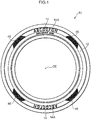
- FIG. 1 A side view of a pneumatic tire 10 relating to the present embodiment is shown in Fig. 1 .
- the tire peripheral direction is indicated by U
- the tire radial direction is indicated by R.
- Emblem portions 14 and side decorative bands 46 are formed at a tire side portion 12 of the pneumatic tire 10.
- the emblem portions 14 are made to be band-shaped circular-arc shapes, and are formed at two places at positions that are symmetrical with respect to a tire central axis CE (see Fig. 1 ).
- An emblem 14A is disposed at the emblem portion 14.
- the emblem 14A is expressed by characters such as "ABCDEFGH" for example that are marked on a smooth surface.
- the side decorative bands 46 are made to be a circular-arc shapes that run along the tire peripheral direction U, and four thereof are formed so as to be adjacent to the respective both end portions of the emblem portions 14.
- a decorative concave portion 48 is formed at the side decorative band 46.
- the decorative concave portion 48 is a shape that is recessed from the outer surface of the tire side portion 12, and structures the outer shape of the side decorative band 46.
- First direction ridge patterns 50 that serve as first ridge portions and second direction ridge patterns 60 that serve as second ridge portions are disposed alternately at a bottom surface 48A of the decorative concave portion 48.
- the first direction ridge patterns 50 and the second direction ridge patterns 60 are the same shapes and only the placement angles thereof differ.
- the first direction ridge pattern 50 is substantially square, and, as shown in Fig. 3 , is structured by a main ridge region 54 and a sub-ridge region 58 that are substantially rectangular.
- first main ridges 62E, 52A, 52B are disposed in parallel so as to be parallel to one another at the main ridge region 54.
- the first main ridges 62E, 52A, 52B extend in a first direction X that is inclined with respect to the tire peripheral direction U.
- the first main ridges 52A, 52B extend from one end side to the other end side of the square of the first direction ridge pattern 50.
- the first main ridge 62E extends from the one end side of the square of the first direction ridge pattern 50, and is connected to one end of a first main ridge 62B of the second direction ridge pattern 60.
- the first main ridges 52A, 52B, 62E project-out from the bottom surface 48A at height H3.
- the height H3 is set within the range of 0.08 to 3.0 mm.
- One end side of the first main ridge 52A and one end side of the first main ridge 52B are connected by an end portion ridge 52C.
- the end portion ridge 52C projects-out at height H3 from the bottom surface 48A.
- the end portion ridge 52C extends from one end side of the first main ridge 52A to one end side of the first main ridge 52B, in the direction orthogonal to the first direction X.
- a substantially U-shaped ridge which extends from another end side to one end side of the first direction ridge pattern 50 and is bent-back at the one end side and returns to the other end side, is formed by the first main ridges 52A, 52B and the end portion ridge 52C.
- a short connecting ridge 52D is formed at the other end side of the first main ridge 52A.
- the short connecting ridge 52D is a portion of the adjacent second direction ridge pattern 60, and is bent at a substantial right angle from the other end of the first main ridge 52A toward the side opposite the first main ridge 52B, and is formed to the corner portion of the first direction ridge pattern 50.
- a second main ridge 52E is formed at the other end side of the first main ridge 52B.
- the second main ridge 52E also is a portion of the adjacent second direction ridge pattern 60, and is bent at a substantial right angle from the other end of the first main ridge 52B toward the side opposite the first main ridge 52A, and is formed to the corner portion of the first direction ridge pattern 50.
- the cross-sectional shapes of the first main ridges 62E, 52A, 52B, the end portion ridge 52C, the short connecting ridge 52D and the second main ridge 52E are trapezoidal shapes that gradually become narrower from the bottom surface 48A, and the bottom surfaces thereof are width W3.
- the width W3 is set within the range of 0.08 to 3.0 mm.
- first sub-ridges 56A, 56B, 56C, 56D are formed in parallel so as to be parallel to one another.
- the first sub-ridges 56A, 56B, 56C, 56D project-out from the bottom surface 48A at height H4 that is lower than the height H3, and extend in the first direction X. Further, the other ends thereof are connected to the second main ridge 52E, and the one ends thereof extend to the other end side of the square of the first direction ridge pattern 50.
- the height H4 is set within the range of 0.05 to 2.0 mm.
- One end side of the first sub-ridge 56A and one end side of the first sub-ridge 56B are connected by an end portion ridge 56E, and one end side of the first sub-ridge 56C and one end side of the first sub-ridge 56D are connected by an end portion ridge 56F.
- the end portion ridges 56E, 56F are disposed in the direction orthogonal to the first direction X.
- Substantially U-shaped ridges which extend from the second main ridge 52E of the first direction ridge pattern 50 to the one end side and are bent-back at the one end side and return to the second main ridge 52E, are formed by the first sub-ridges 56A, 56B and the end portion ridge 56E, and the first sub-ridges 56C, 56D and the end portion ridge 56F, respectively. Further, at the other end side, the first sub-ridges 56A, 56B are connected via the second main ridge 52E, and the first sub-ridges 56C, 56D are connected via the second main ridge 52E.
- the region from the end portion, which is at the second main ridge 52E side, of the first sub-ridge 56A to the end portion, which is at the second main ridge 52E side, of the first sub-ridge 56D is a continuous sub-ridge 56R that is a continuous one ridge.
- the first sub-ridges 56A, 56B, 56C, 56D are trapezoidal shapes that gradually become narrower from the bottom surface 48A, and the bottom surfaces thereof are width W4.
- the width W4 is set within the range of 0.05 to 2.0 mm.
- the end portion ridges 56E, 56F also are trapezoidal shapes that gradually become narrower from the bottom surface 48A, and the bottom surfaces thereof are the width W4.
- a groove portion 53F of groove width M8 is formed between the first main ridge 62E and the first main ridge 52A, and a groove portion 53A of groove width M10 is structured between the first main ridge 52A and the first main ridge 52B, and a groove portion 53B of groove width M12 is formed between the first main ridge 52B and the first sub-ridge 56A.
- a groove portion 53C of groove width M14 is formed between the first sub-ridge 56A and the first sub-ridge 56B, and a groove portion 53D of groove width M16 is formed between the first sub-ridge 56B and the first sub-ridge 56C, and a groove portion 53E of groove width M18 is formed between the first sub-ridge 56C and the first sub-ridge 56D.
- the groove portion 53F is the widest, and the groove widths become more narrow in order toward the first sub-ridge 56D side, and M8 > M10 > M12 > M14 > M16 > M18.
- the second direction ridge pattern 60 has a shape that is similar to the first direction ridge pattern 50, but is disposed as if the first direction ridge pattern 50 is rotated by 90°.
- Main ridge region 64 and sub-ridge region 68 of the second direction ridge pattern 60 correspond respectively to the main ridge region 54 and the sub-ridge region 58 of the first direction ridge pattern 50.
- Second main ridges 52E, 62A, 62B, an end portion ridge 62C, and the short connecting ridge 52D of the second direction ridge pattern 60 correspond to the first main ridges 62E, 52A, 52B, the end portion ridge 52C, and the short connecting ridge 62D of the first direction ridge pattern 50.
- second sub-ridges 66A, 66B, 66C, 66D and end portion ridges 66E, 66F of the second direction ridge pattern 60 correspond to the sub-ridges 56A, 56B, 56C, 56D and the end portion ridges 56E, 56F of the first direction ridge pattern 50.
- the second main ridges 52E, 62A, 62B and the second sub-ridges 66A, 66B, 66C, 66D extend in a second direction Y that is inclined with respect to the tire radial direction R.
- a groove portion 63F, a groove portion 63A, a groove portion 63B, a groove portion 63C, a groove portion 63D, a groove portion 63E of the second direction ridge pattern 60 correspond to the groove portion 53F, the groove portion 53A, the groove portion 53B, the groove portion 53C, the groove portion 53D, the groove portion 53E of the first direction ridge pattern 50.
- the first direction ridge pattern 50 and the second direction ridge pattern 60 are disposed in the form of a lattice so as to be lined-up alternately at the bottom surface 48A of the decorative recess portion 48, and the entire decorative recess portion 48 is decorated by the first direction ridge pattern 50 and the second direction ridge pattern 60.
- the short connecting ridge 52D and the first main ridge 62E, and the second main ridge 52E and the short connecting ridge 62D, of the first direction ridge pattern 50 and the second direction ridge pattern 60 that are adjacent to one another are connected together. Due thereto, ridges of the heights H3, H4 are connected as one ridge from the one end to the other end of the decorative concave portion 48, and a continuous main ridge 51 is formed.
- the continuous main ridge 51 extends in a direction intersecting the tire peripheral direction.
- first sub-ridges 56A through 56D and the second sub-ridges 66A through 66D of the first direction ridge pattern 50 and the second direction ridge pattern 60 that are adjacent to one another form a 90° angle and are adjacent, and form a zigzag sub-ridgeline 61 that is zigzag-shaped.
- the zigzag sub-ridgeline 61 extends in the same direction as the continuous main ridge 51.
- the continuous main ridge 51 and the zigzag sub-ridgeline 61 are disposed alternately in the tire peripheral direction.
- the side decorative band 46 is formed due to the first direction ridge pattern 50, which includes the main ridge region 54 and the sub-ridge region 58 at which the projecting heights of the ridges differ, and the second direction ridge pattern 60, which includes the main ridge region 64 and the sub-ridge region 68, being lined-up alternately with the extending directions of the ridges thereof differing from one another. Due thereto, incident light can be reflected in multiple directions, and the side decorative band 46 can be made to look three-dimensional, and, at the tire side portion, a difference in shading that is due to the difference in the reflection of light (sunlight, ambient light, or the like) can be produced effectively.
- the side decorative band 46 has the continuous main ridge 51, which is zigzag-shaped and is structured by the main ridge regions 54, 64, and the zigzag sub-ridgeline 61, which is zigzag-shaped and is structured by the sub-ridge regions 58, 68. Accordingly, incident light can be reflected effectively in more directions, and, at the tire side portion, the difference in shading that is due to the difference in the reflection of light can be produced effectively.
- the continuous main ridge 51 is continuous as one ridge from the one end to the other end of the decorative concave portion 48.
- the continuous main ridge 51 in which the first main ridges 52A, 52B, 62E and the second main ridges 62A, 62B, 52E are connected and that is continuous from one end to the other end of the decorative concave portion, is formed. Accordingly, vertical movement of the aforementioned blade is unnecessary, and grooves for the main ridges can be machined easily.
- the continuous main ridge 51 and the zigzag sub-ridgeline 61 extend in a direction intersecting the tire peripheral direction U. Accordingly, propagation of cracks that arise easily along the tire peripheral direction U can be suppressed. Moreover, because the continuous main ridge 51 and the zigzag sub-ridgeline 61 are disposed alternately in the tire peripheral direction, these portions can more effectively be made to look three-dimensional by utilizing the difference in the heights.
- the groove width between adjacent ridges becomes gradually more narrow from the side of the first main ridge 52A, the second main ridge 62A toward the first sub-ridge 56D, the second sub-ridge 66D side. Due thereto, an effect that is as if the heights of the ridges are changing within the main ridge region 54, 64 and within the sub-ridge region 58, 68 respectively, can be produced.
- the groove widths of the groove portions 53A through 53F which are formed between the first main ridge 52A through the first sub-ridge 56D, are varied.
- the groove widths M8 through M18 may be such that the groove widths of the groove portions 53A, 53B, 53F within the main ridge region 54 are a same width M19, and the groove widths of the groove portions 53C, 53D, 53E within the sub-ridge region 58 are a same width M20.
- the groove width M19 of the groove widths 53A, 53B, 53F of the groove portions within the main ridge region 54 is made to be wider than the groove width M20 of the groove portions 53C through 53E within the sub-ridge region 58.
- the groove widths of the groove portions that are formed between the second main ridge 62A through the second sub-ridge 66D at the second direction ridge pattern 60 can be varied similarly.
- the groove widths M8 through M18 may all be made to be a same width M22.
- the groove widths vary, incident light can be reflected effectively in more directions, and, at the tire side portion, the difference in shading that is due to the difference in the reflection of light can be produced effectively.
- the projecting heights of the ridges are two steps, but the projecting heights may be made to be gradually shorter from the side of the first main ridge 52A, the second main ridge 62A toward the first sub-ridge 56D, the first sub-ridge 66C side.
- the projecting heights of the ridges may all be made to be the same.
- incident light can be reflected effectively in more directions, and, at the tire side portion, the difference in shading that is due to the difference in the reflection of light can be produced effectively.
- the first direction X and the second direction Y are orthogonal, but the directions do not necessarily have to be orthogonal. Because the angle between the first direction X and the second direction Y is 90°, the difference in shading that is due to the difference in the reflection of the light reflected by the respective ridges can be produced more effectively.
Landscapes
- Engineering & Computer Science (AREA)
- Mechanical Engineering (AREA)
- Tires In General (AREA)
Abstract
Description
- The present invention relates to a pneumatic tire in which plural ridges are formed at a tire side portion.
- The provision of side decorative bands, in which plural straight or curved ridges are arrayed in parallel, at the side portions of a tire has been carried out widely. Making the thickness of the tire sides thin in order to aim for decreased weight of the tire has been carried out, but, if the thickness of the tire sides is made thin, there are cases in which convexity and concavity, which is caused by the end portions of members such as the belts or the like, appears at the surfaces of the tire sides. The aforementioned side decorative belt is effective in making such convexity and concavity inconspicuous.
- For example, a side decorative belt that is structured by decorative element A1, decorative element B1 and decorative element C1 is disclosed in Patent Document 1. By forming this side decorative belt at the tire side portion, the effect of making convexity and concavity of the side portion of the tire inconspicuous is achieved.
- Patent Document 1: Japanese Patent Application Laid-Open (
JP-A) No. 2011-126335 - By the way, in a case in which a side decorative band is formed at a tire side portion, there is the need to carry out, on the mold that is used when vulcanizing the tire, convex/concave machining that makes the mold correspond to the side decorative band. At the time of carrying out this convex/concave machining, if the ridges break-off, each time a ridge breaks-off, the need arises to carry out vertical movement of the blade for machining, and the machining requires time and labor.
- In view of the above-described circumstances, the subject of the present invention is the provision of a pneumatic tire in which convexity and concavity of a tire side portion is made inconspicuous, and a side decorative region of the tire side portion can be formed easily. Solution to Problem
- A pneumatic tire relating to a first aspect comprises: a first ridge portion having a plurality of first main ridges, which project-out from a bottom surface of a side decorative region formed in a tire side portion and extend in parallel in a first direction, and having a first connecting ridge, which extends in a direction intersecting the first direction and connects together end portions of the first main ridges that are adjacent; and a second ridge portion having a plurality of second main ridges, which project out from the bottom surface of the side decorative region and extend in parallel in a second direction that is different than the first direction, and having a second connecting ridge, which extends in a direction intersecting the second direction and connects together end portions of the second main ridges that are adjacent, wherein a plurality of continuous main ridges, in which the first main ridges and the second main ridges are disposed alternately and connected together, and that are continuous from one end to another end of the side decorative region, are formed.
- In the pneumatic tire relating to the first aspect, the first ridge portion in which the first main ridges are formed and the second ridge portion in which the second main ridges are formed are disposed at the side decorative region of the tire side portion. The first main ridges extend in the first direction, and a plurality thereof are disposed in parallel. The first main ridges that are adjacent are connected to one another by the first connecting ridge and become a single ridge. The second main ridges extend in the second direction, and a plurality thereof are disposed in parallel. The second main ridges that are adjacent are connected to one another by the second connecting ridge and become a single ridge. Further, plural continuous main ridges, in which the first main ridges and the second main ridges are disposed alternately and connected together, and that are continuous from one end to the other end of the side decorative region, are formed.
- In accordance with the present invention, light that is incident on the tire side portion can be reflected in multiple directions by the first main ridges and the second main ridges that extend in respectively different directions. Accordingly, at the tire side portion, a difference in shading that is due to the difference in the reflection of light (sunlight, ambient light, or the like) can be produced effectively.
- Further, the continuous main ridges, in which the first main ridges and the second main ridges are connected and that are continuous from one end to another end of the side decorative band, are structured. Accordingly, there is no need for vertical movement of a blade for mold machining, and grooves for the first main ridges and the second main ridges can be machined easily.
- A pneumatic tire relating to a second aspect further comprises a plurality of sub-ridges that project out from the bottom surface of the side decorative region, are disposed between the first main ridges and the second main ridges, extend in the first direction or the second direction, and are disposed in parallel to one another.
- In accordance with the pneumatic tire relating to the second aspect, a difference in shading that is due to the difference in the reflection of light can be produced more effectively by the sub-ridges that extend in the first direction or the second direction.
- A pneumatic tire relating to a third aspect has the feature that the first ridge portion and the second ridge portion are disposed alternately in a form of a lattice.
- In accordance with the pneumatic tire relating to the third aspect, the first ridge portion and the second ridge portion, at which the extending directions of the ridges differ, are disposed alternately in the form of a lattice. Therefore, the difference in shading that is due to the difference in the reflection of light can be produced more effectively.
- A pneumatic tire relating to a fourth aspect has the feature that an interval between the first main ridges that are adjacent to one another and an interval between the second main ridges that are adjacent to one another are wider than an interval between the sub-ridges that are adjacent to one another.
- In accordance with the pneumatic tire relating to the fourth aspect, by making the interval between the first main ridges and the interval between the second main ridges wider than the interval between the sub-ridges, these portions can be made to look three-dimensional by utilizing the difference in the reflection of light that is due to the difference in the intervals.
- A pneumatic tire relating to a fifth aspect has the feature that projecting heights of the first main ridges and the second main ridges from the bottom surface are higher than that of the sub-ridges.
- In accordance with the pneumatic tire relating to the fifth aspect, the projecting heights of the first main ridges and the second main ridges from the bottom surface are higher than that of the sub-ridges. Therefore, these portions can be made to look three-dimensional by utilizing the difference in the reflection of light that is due to the difference in heights.
- A pneumatic tire relating to a sixth aspect has the feature that the sub-ridges include first sub-ridges that are disposed at the first ridge portion and second sub-ridges that are disposed at the second ridge portion, and the first sub-ridges are formed so as to be continuous within the first ridge portion, and the second sub-ridges are formed so as to be continuous within the second ridge portion.
- In accordance with the pneumatic tire relating to the sixth aspect, the sub-ridges as well are formed continuously as one sub-ridge within the first ridge portion and within the second ridge portion. Therefore, there is no need for vertical movement of a blade for mold machining within the range in which the sub-ridges are formed continuously, and grooves for the first sub-ridges and the second sub-ridges can be machined easily.
- A pneumatic tire relating to a seventh aspect has the feature that the first direction and the second direction are orthogonal.
- In accordance with the pneumatic tire relating to the seventh aspect, because the angle between the first direction and the second direction is 90°, the difference in shading that is due to the difference in the reflection of the light reflected by the respective regions can be produced more effectively.
- In accordance with the present invention, convexity and concavity of a tire side portion is made inconspicuous, and a side decorative band of the tire side portion can be formed easily.
-
-
Fig. 1 is a side view of a pneumatic tire relating to a present embodiment. -
Fig. 2 is a portion of a side decorative portion of the pneumatic tire relating to the present embodiment. -
Fig. 3 is a partial, enlarged view of the side decorative portion of the pneumatic tire relating to the present embodiment. -
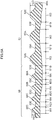
Fig. 4 is a cross-sectional view along line 4-4 ofFig. 3 . -
Fig. 5A is a cross-sectional view of a modified example of the side decorative portion of the tire of the present embodiment. -
Fig. 5B is a cross-sectional view of a modified example of the side decorative portion of the tire of the present embodiment. - An embodiment of the present invention is described hereinafter with reference to the drawings. A side view of a
pneumatic tire 10 relating to the present embodiment is shown inFig. 1 . In the present embodiment, the tire peripheral direction is indicated by U, and the tire radial direction is indicated by R. -
Emblem portions 14 and sidedecorative bands 46 are formed at atire side portion 12 of thepneumatic tire 10. - The
emblem portions 14 are made to be band-shaped circular-arc shapes, and are formed at two places at positions that are symmetrical with respect to a tire central axis CE (seeFig. 1 ). Anemblem 14A is disposed at theemblem portion 14. Theemblem 14A is expressed by characters such as "ABCDEFGH" for example that are marked on a smooth surface. - The side
decorative bands 46 are made to be a circular-arc shapes that run along the tire peripheral direction U, and four thereof are formed so as to be adjacent to the respective both end portions of theemblem portions 14. - As shown in
Fig. 2 , a decorativeconcave portion 48 is formed at the sidedecorative band 46. The decorativeconcave portion 48 is a shape that is recessed from the outer surface of thetire side portion 12, and structures the outer shape of the sidedecorative band 46. Firstdirection ridge patterns 50 that serve as first ridge portions and seconddirection ridge patterns 60 that serve as second ridge portions are disposed alternately at abottom surface 48A of the decorativeconcave portion 48. The firstdirection ridge patterns 50 and the seconddirection ridge patterns 60 are the same shapes and only the placement angles thereof differ. - The first
direction ridge pattern 50 is substantially square, and, as shown inFig. 3 , is structured by amain ridge region 54 and asub-ridge region 58 that are substantially rectangular. - Three first
main ridges main ridge region 54. The firstmain ridges main ridges direction ridge pattern 50. The firstmain ridge 62E extends from the one end side of the square of the firstdirection ridge pattern 50, and is connected to one end of a firstmain ridge 62B of the seconddirection ridge pattern 60. As shown inFig. 4 , the firstmain ridges bottom surface 48A at height H3. The height H3 is set within the range of 0.08 to 3.0 mm. - One end side of the first
main ridge 52A and one end side of the firstmain ridge 52B are connected by an end portion ridge 52C. In the same way as the firstmain ridges bottom surface 48A. The end portion ridge 52C extends from one end side of the firstmain ridge 52A to one end side of the firstmain ridge 52B, in the direction orthogonal to the first direction X. A substantially U-shaped ridge, which extends from another end side to one end side of the firstdirection ridge pattern 50 and is bent-back at the one end side and returns to the other end side, is formed by the firstmain ridges - A short connecting
ridge 52D is formed at the other end side of the firstmain ridge 52A. The short connectingridge 52D is a portion of the adjacent seconddirection ridge pattern 60, and is bent at a substantial right angle from the other end of the firstmain ridge 52A toward the side opposite the firstmain ridge 52B, and is formed to the corner portion of the firstdirection ridge pattern 50. A secondmain ridge 52E is formed at the other end side of the firstmain ridge 52B. The secondmain ridge 52E also is a portion of the adjacent seconddirection ridge pattern 60, and is bent at a substantial right angle from the other end of the firstmain ridge 52B toward the side opposite the firstmain ridge 52A, and is formed to the corner portion of the firstdirection ridge pattern 50. - The cross-sectional shapes of the first
main ridges ridge 52D and the secondmain ridge 52E are trapezoidal shapes that gradually become narrower from thebottom surface 48A, and the bottom surfaces thereof are width W3. The width W3 is set within the range of 0.08 to 3.0 mm. - At the
sub-ridge region 58, four first sub-ridges 56A, 56B, 56C, 56D are formed in parallel so as to be parallel to one another. The first sub-ridges 56A, 56B, 56C, 56D project-out from thebottom surface 48A at height H4 that is lower than the height H3, and extend in the first direction X. Further, the other ends thereof are connected to the secondmain ridge 52E, and the one ends thereof extend to the other end side of the square of the firstdirection ridge pattern 50. The height H4 is set within the range of 0.05 to 2.0 mm. - One end side of the first sub-ridge 56A and one end side of the first sub-ridge 56B are connected by an
end portion ridge 56E, and one end side of the first sub-ridge 56C and one end side of the first sub-ridge 56D are connected by anend portion ridge 56F. Theend portion ridges main ridge 52E of the firstdirection ridge pattern 50 to the one end side and are bent-back at the one end side and return to the secondmain ridge 52E, are formed by the first sub-ridges 56A, 56B and theend portion ridge 56E, and the first sub-ridges 56C, 56D and theend portion ridge 56F, respectively. Further, at the other end side, the first sub-ridges 56A, 56B are connected via the secondmain ridge 52E, and the first sub-ridges 56C, 56D are connected via the secondmain ridge 52E. Due thereto, within the firstdirection ridge pattern 50, the region from the end portion, which is at the secondmain ridge 52E side, of the first sub-ridge 56A to the end portion, which is at the secondmain ridge 52E side, of the first sub-ridge 56D is a continuous sub-ridge 56R that is a continuous one ridge. By forming the ridges to be continuous in this way, at the time of machining the mold for the ridges, there is no need for vertical movement of a blade for mold machining within the range in which the ridges are formed continuously, and the grooves can be machined easily. - As shown in
Fig. 4 , the first sub-ridges 56A, 56B, 56C, 56D are trapezoidal shapes that gradually become narrower from thebottom surface 48A, and the bottom surfaces thereof are width W4. The width W4 is set within the range of 0.05 to 2.0 mm. Further, theend portion ridges bottom surface 48A, and the bottom surfaces thereof are the width W4. - A
groove portion 53F of groove width M8 is formed between the firstmain ridge 62E and the firstmain ridge 52A, and agroove portion 53A of groove width M10 is structured between the firstmain ridge 52A and the firstmain ridge 52B, and agroove portion 53B of groove width M12 is formed between the firstmain ridge 52B and the first sub-ridge 56A. Agroove portion 53C of groove width M14 is formed between the first sub-ridge 56A and the first sub-ridge 56B, and agroove portion 53D of groove width M16 is formed between the first sub-ridge 56B and the first sub-ridge 56C, and agroove portion 53E of groove width M18 is formed between the first sub-ridge 56C and the first sub-ridge 56D. With respect to the groove widths of these groove portions, thegroove portion 53F is the widest, and the groove widths become more narrow in order toward the first sub-ridge 56D side, and M8 > M10 > M12 > M14 > M16 > M18. - The second
direction ridge pattern 60 has a shape that is similar to the firstdirection ridge pattern 50, but is disposed as if the firstdirection ridge pattern 50 is rotated by 90°.Main ridge region 64 andsub-ridge region 68 of the seconddirection ridge pattern 60 correspond respectively to themain ridge region 54 and thesub-ridge region 58 of the firstdirection ridge pattern 50. Secondmain ridges end portion ridge 62C, and the short connectingridge 52D of the seconddirection ridge pattern 60 correspond to the firstmain ridges ridge 62D of the firstdirection ridge pattern 50. Further, second sub-ridges 66A, 66B, 66C, 66D and endportion ridges direction ridge pattern 60 correspond to the sub-ridges 56A, 56B, 56C, 56D and theend portion ridges direction ridge pattern 50. The secondmain ridges A groove portion 63F, agroove portion 63A, agroove portion 63B, a groove portion 63C, agroove portion 63D, agroove portion 63E of the seconddirection ridge pattern 60 correspond to thegroove portion 53F, thegroove portion 53A, thegroove portion 53B, thegroove portion 53C, thegroove portion 53D, thegroove portion 53E of the firstdirection ridge pattern 50. - The first
direction ridge pattern 50 and the seconddirection ridge pattern 60 are disposed in the form of a lattice so as to be lined-up alternately at thebottom surface 48A of thedecorative recess portion 48, and the entiredecorative recess portion 48 is decorated by the firstdirection ridge pattern 50 and the seconddirection ridge pattern 60. The short connectingridge 52D and the firstmain ridge 62E, and the secondmain ridge 52E and the short connectingridge 62D, of the firstdirection ridge pattern 50 and the seconddirection ridge pattern 60 that are adjacent to one another are connected together. Due thereto, ridges of the heights H3, H4 are connected as one ridge from the one end to the other end of the decorativeconcave portion 48, and a continuousmain ridge 51 is formed. The continuousmain ridge 51 extends in a direction intersecting the tire peripheral direction. - Further, the first sub-ridges 56A through 56D and the second sub-ridges 66A through 66D of the first
direction ridge pattern 50 and the seconddirection ridge pattern 60 that are adjacent to one another form a 90° angle and are adjacent, and form azigzag sub-ridgeline 61 that is zigzag-shaped. Thezigzag sub-ridgeline 61 extends in the same direction as the continuousmain ridge 51. - The continuous
main ridge 51 and thezigzag sub-ridgeline 61 are disposed alternately in the tire peripheral direction. - As described above, the side
decorative band 46 is formed due to the firstdirection ridge pattern 50, which includes themain ridge region 54 and thesub-ridge region 58 at which the projecting heights of the ridges differ, and the seconddirection ridge pattern 60, which includes themain ridge region 64 and thesub-ridge region 68, being lined-up alternately with the extending directions of the ridges thereof differing from one another. Due thereto, incident light can be reflected in multiple directions, and the sidedecorative band 46 can be made to look three-dimensional, and, at the tire side portion, a difference in shading that is due to the difference in the reflection of light (sunlight, ambient light, or the like) can be produced effectively. - Further, the side
decorative band 46 has the continuousmain ridge 51, which is zigzag-shaped and is structured by themain ridge regions zigzag sub-ridgeline 61, which is zigzag-shaped and is structured by thesub-ridge regions - Further, the continuous
main ridge 51 is continuous as one ridge from the one end to the other end of the decorativeconcave portion 48. At the time of machining a mold for forming the firstmain ridges main ridges main ridges main ridges main ridge 51, in which the firstmain ridges main ridges - Further, at the side
decorative band 46, the continuousmain ridge 51 and thezigzag sub-ridgeline 61 extend in a direction intersecting the tire peripheral direction U. Accordingly, propagation of cracks that arise easily along the tire peripheral direction U can be suppressed. Moreover, because the continuousmain ridge 51 and thezigzag sub-ridgeline 61 are disposed alternately in the tire peripheral direction, these portions can more effectively be made to look three-dimensional by utilizing the difference in the heights. - Further, at the first
direction ridge pattern 50 and the seconddirection ridge pattern 60, the groove width between adjacent ridges becomes gradually more narrow from the side of the firstmain ridge 52A, the secondmain ridge 62A toward the first sub-ridge 56D, the second sub-ridge 66D side. Due thereto, an effect that is as if the heights of the ridges are changing within themain ridge region sub-ridge region - Note that, in the present embodiment, at the first
direction ridge pattern 50, the groove widths of thegroove portions 53A through 53F, which are formed between the firstmain ridge 52A through the first sub-ridge 56D, are varied. However, as shown inFig. 5A , the groove widths M8 through M18 may be such that the groove widths of thegroove portions main ridge region 54 are a same width M19, and the groove widths of thegroove portions sub-ridge region 58 are a same width M20. In this case, the groove width M19 of thegroove widths main ridge region 54 is made to be wider than the groove width M20 of thegroove portions 53C through 53E within thesub-ridge region 58. Note that the groove widths of the groove portions that are formed between the secondmain ridge 62A through the second sub-ridge 66D at the seconddirection ridge pattern 60 can be varied similarly. - Further, as shown in
Fig. 5B , the groove widths M8 through M18 may all be made to be a same width M22. In the present embodiment, because the groove widths vary, incident light can be reflected effectively in more directions, and, at the tire side portion, the difference in shading that is due to the difference in the reflection of light can be produced effectively. - Further, in the present embodiment, at the first
direction ridge pattern 50 and the seconddirection ridge pattern 50, the projecting heights of the ridges are two steps, but the projecting heights may be made to be gradually shorter from the side of the firstmain ridge 52A, the secondmain ridge 62A toward the first sub-ridge 56D, the first sub-ridge 66C side. - Moreover, at the first
direction ridge pattern 50 and the seconddirection ridge pattern 50, the projecting heights of the ridges may all be made to be the same. In the present embodiment, because the heights are varied, incident light can be reflected effectively in more directions, and, at the tire side portion, the difference in shading that is due to the difference in the reflection of light can be produced effectively. - Further, in the present embodiment, there is a pattern in which the first direction X and the second direction Y are orthogonal, but the directions do not necessarily have to be orthogonal. Because the angle between the first direction X and the second direction Y is 90°, the difference in shading that is due to the difference in the reflection of the light reflected by the respective ridges can be produced more effectively.
- The disclosure of Japanese Application: Patent Application No.
2014-218555 - All publications, patent applications, and technical standards mentioned in the present specification are incorporated by reference into the present specification to the same extent as if such individual publication, patent application, or technical standard was specifically and individually indicated to be incorporated by reference.
Claims (7)
- A pneumatic tire comprising:a first ridge portion having a plurality of first main ridges, which project out from a bottom surface of a side decorative region formed in a tire side portion and extend in parallel in a first direction, and having a first connecting ridge, which extends in a direction intersecting the first direction and connects together end portions of the first main ridges that are adjacent; anda second ridge portion having a plurality of second main ridges, which project out from the bottom surface of the side decorative region and extend in parallel in a second direction that is different than the first direction, and having a second connecting ridge, which extends in a direction intersecting the second direction and connects together end portions of the second main ridges that are adjacent,wherein a plurality of continuous main ridges, in which the first main ridges and the second main ridges are disposed alternately and connected together, and that are continuous from one end to another end of the side decorative region, are formed.
- The pneumatic tire of Claim 1, further comprising a plurality of sub-ridges that project out from the bottom surface of the side decorative region, are disposed between the first main ridges and the second main ridges, extend in the first direction or the second direction, and are disposed in parallel to one another.
- The pneumatic tire of Claim 1 or Claim 2, wherein the first ridge portion and the second ridge portion are disposed alternately in a form of a lattice.
- The pneumatic tire of Claim 2 or Claim 3, wherein an interval between the first main ridges that are adjacent to one another and an interval between the second main ridges that are adjacent to one another are wider than an interval between the sub-ridges that are adjacent to one another.
- The pneumatic tire of any one of Claims 2 through 4, wherein projecting heights of the first main ridges and the second main ridges from the bottom surface are higher than that of the sub-ridges.
- The pneumatic tire of any one of Claims 2 through 5, wherein:the sub-ridges include first sub-ridges that are disposed at the first ridge portion and second sub-ridges that are disposed at the second ridge portion, andthe first sub-ridges are formed so as to be continuous within the first ridge portion, and the second sub-ridges are formed so as to be continuous within the second ridge portion.
- The pneumatic tire of any one of Claims 1 through 5, wherein the first direction and the second direction are orthogonal.
Applications Claiming Priority (2)
| Application Number | Priority Date | Filing Date | Title |
|---|---|---|---|
| JP2014218555A JP6392078B2 (en) | 2014-10-27 | 2014-10-27 | Pneumatic tire |
| PCT/JP2015/078385 WO2016067856A1 (en) | 2014-10-27 | 2015-10-06 | Pneumatic tire |
Publications (3)
| Publication Number | Publication Date |
|---|---|
| EP3213934A1 true EP3213934A1 (en) | 2017-09-06 |
| EP3213934A4 EP3213934A4 (en) | 2017-11-08 |
| EP3213934B1 EP3213934B1 (en) | 2018-12-12 |
Family
ID=55857200
Family Applications (1)
| Application Number | Title | Priority Date | Filing Date |
|---|---|---|---|
| EP15854424.7A Not-in-force EP3213934B1 (en) | 2014-10-27 | 2015-10-06 | Pneumatic tire |
Country Status (5)
| Country | Link |
|---|---|
| US (1) | US10596859B2 (en) |
| EP (1) | EP3213934B1 (en) |
| JP (1) | JP6392078B2 (en) |
| CN (1) | CN107148363B (en) |
| WO (1) | WO2016067856A1 (en) |
Families Citing this family (6)
| Publication number | Priority date | Publication date | Assignee | Title |
|---|---|---|---|---|
| JP2016144704A (en) * | 2016-05-16 | 2016-08-12 | 京楽産業.株式会社 | Game machine |
| JP6270910B2 (en) * | 2016-05-16 | 2018-01-31 | 京楽産業.株式会社 | Game machine |
| JP2016165544A (en) * | 2016-05-20 | 2016-09-15 | 京楽産業.株式会社 | Game machine |
| JP2016165545A (en) * | 2016-05-20 | 2016-09-15 | 京楽産業.株式会社 | Game machine |
| DE102021206548A1 (en) * | 2021-06-24 | 2022-12-29 | Continental Reifen Deutschland Gmbh | Vehicle Pneumatic Tires |
| TWI896058B (en) * | 2024-03-28 | 2025-09-01 | 正新橡膠工業股份有限公司 | Patterned structure of tire sidewall |
Family Cites Families (12)
| Publication number | Priority date | Publication date | Assignee | Title |
|---|---|---|---|---|
| US5303758A (en) * | 1992-06-15 | 1994-04-19 | The Goodyear Tire & Rubber Company | Tire sidewall design patterns |
| JPH11291722A (en) * | 1998-04-03 | 1999-10-26 | Bridgestone Corp | Pneumatic tire provided with annular ornamental unit formed by many ridges |
| JP2000118208A (en) * | 1998-10-09 | 2000-04-25 | Bridgestone Corp | Pneumatic tire provided with many rectangular decorative bodies |
| JP4687811B2 (en) * | 2009-04-10 | 2011-05-25 | 横浜ゴム株式会社 | Pneumatic tire |
| WO2011062241A1 (en) | 2009-11-19 | 2011-05-26 | 株式会社ブリヂストン | Tire |
| JP5461161B2 (en) * | 2009-12-07 | 2014-04-02 | 株式会社ブリヂストン | tire |
| JP5675154B2 (en) * | 2010-04-15 | 2015-02-25 | 株式会社ブリヂストン | Pneumatic tire |
| DE102012104890A1 (en) * | 2012-06-05 | 2013-12-05 | Continental Reifen Deutschland Gmbh | Polymer product, preferably vehicle tires |
| JP5603389B2 (en) | 2012-08-28 | 2014-10-08 | 株式会社ユニバーサルエンターテインメント | Game machine |
| JP5789274B2 (en) * | 2013-01-16 | 2015-10-07 | 住友ゴム工業株式会社 | Pneumatic tire |
| JP6197987B2 (en) * | 2013-02-27 | 2017-09-20 | 横浜ゴム株式会社 | Pneumatic tire |
| JP5869019B2 (en) | 2014-03-05 | 2016-02-24 | 株式会社ブリヂストン | tire |
-
2014
- 2014-10-27 JP JP2014218555A patent/JP6392078B2/en not_active Expired - Fee Related
-
2015
- 2015-10-06 WO PCT/JP2015/078385 patent/WO2016067856A1/en not_active Ceased
- 2015-10-06 EP EP15854424.7A patent/EP3213934B1/en not_active Not-in-force
- 2015-10-06 US US15/519,556 patent/US10596859B2/en active Active
- 2015-10-06 CN CN201580058013.7A patent/CN107148363B/en not_active Expired - Fee Related
Also Published As
| Publication number | Publication date |
|---|---|
| CN107148363B (en) | 2019-03-26 |
| JP2016084043A (en) | 2016-05-19 |
| CN107148363A (en) | 2017-09-08 |
| EP3213934A4 (en) | 2017-11-08 |
| WO2016067856A1 (en) | 2016-05-06 |
| EP3213934B1 (en) | 2018-12-12 |
| US20170246919A1 (en) | 2017-08-31 |
| US10596859B2 (en) | 2020-03-24 |
| JP6392078B2 (en) | 2018-09-19 |
Similar Documents
| Publication | Publication Date | Title |
|---|---|---|
| US10596857B2 (en) | Pneumatic tire | |
| EP3213934B1 (en) | Pneumatic tire | |
| US10596858B2 (en) | Pneumatic tire | |
| US9365080B2 (en) | Tire | |
| JP5325129B2 (en) | tire | |
| US10532614B2 (en) | Tire | |
| JP6392076B2 (en) | Pneumatic tire | |
| JP6619959B2 (en) | tire | |
| WO2016067940A1 (en) | Pneumatic tire | |
| JP6392077B2 (en) | Pneumatic tire | |
| JP6423295B2 (en) | tire |
Legal Events
| Date | Code | Title | Description |
|---|---|---|---|
| STAA | Information on the status of an ep patent application or granted ep patent |
Free format text: STATUS: THE INTERNATIONAL PUBLICATION HAS BEEN MADE |
|
| PUAI | Public reference made under article 153(3) epc to a published international application that has entered the european phase |
Free format text: ORIGINAL CODE: 0009012 |
|
| STAA | Information on the status of an ep patent application or granted ep patent |
Free format text: STATUS: REQUEST FOR EXAMINATION WAS MADE |
|
| 17P | Request for examination filed |
Effective date: 20170508 |
|
| AK | Designated contracting states |
Kind code of ref document: A1 Designated state(s): AL AT BE BG CH CY CZ DE DK EE ES FI FR GB GR HR HU IE IS IT LI LT LU LV MC MK MT NL NO PL PT RO RS SE SI SK SM TR |
|
| AX | Request for extension of the european patent |
Extension state: BA ME |
|
| A4 | Supplementary search report drawn up and despatched |
Effective date: 20171011 |
|
| RIC1 | Information provided on ipc code assigned before grant |
Ipc: B60C 13/00 20060101AFI20171005BHEP |
|
| DAV | Request for validation of the european patent (deleted) | ||
| DAX | Request for extension of the european patent (deleted) | ||
| GRAP | Despatch of communication of intention to grant a patent |
Free format text: ORIGINAL CODE: EPIDOSNIGR1 |
|
| STAA | Information on the status of an ep patent application or granted ep patent |
Free format text: STATUS: GRANT OF PATENT IS INTENDED |
|
| INTG | Intention to grant announced |
Effective date: 20180626 |
|
| GRAS | Grant fee paid |
Free format text: ORIGINAL CODE: EPIDOSNIGR3 |
|
| GRAA | (expected) grant |
Free format text: ORIGINAL CODE: 0009210 |
|
| STAA | Information on the status of an ep patent application or granted ep patent |
Free format text: STATUS: THE PATENT HAS BEEN GRANTED |
|
| AK | Designated contracting states |
Kind code of ref document: B1 Designated state(s): AL AT BE BG CH CY CZ DE DK EE ES FI FR GB GR HR HU IE IS IT LI LT LU LV MC MK MT NL NO PL PT RO RS SE SI SK SM TR |
|
| REG | Reference to a national code |
Ref country code: GB Ref legal event code: FG4D |
|
| REG | Reference to a national code |
Ref country code: CH Ref legal event code: EP |
|
| REG | Reference to a national code |
Ref country code: AT Ref legal event code: REF Ref document number: 1075451 Country of ref document: AT Kind code of ref document: T Effective date: 20181215 |
|
| REG | Reference to a national code |
Ref country code: DE Ref legal event code: R096 Ref document number: 602015021690 Country of ref document: DE |
|
| REG | Reference to a national code |
Ref country code: IE Ref legal event code: FG4D |
|
| REG | Reference to a national code |
Ref country code: NL Ref legal event code: MP Effective date: 20181212 |
|
| REG | Reference to a national code |
Ref country code: LT Ref legal event code: MG4D |
|
| PG25 | Lapsed in a contracting state [announced via postgrant information from national office to epo] |
Ref country code: NO Free format text: LAPSE BECAUSE OF FAILURE TO SUBMIT A TRANSLATION OF THE DESCRIPTION OR TO PAY THE FEE WITHIN THE PRESCRIBED TIME-LIMIT Effective date: 20190312 Ref country code: LT Free format text: LAPSE BECAUSE OF FAILURE TO SUBMIT A TRANSLATION OF THE DESCRIPTION OR TO PAY THE FEE WITHIN THE PRESCRIBED TIME-LIMIT Effective date: 20181212 Ref country code: HR Free format text: LAPSE BECAUSE OF FAILURE TO SUBMIT A TRANSLATION OF THE DESCRIPTION OR TO PAY THE FEE WITHIN THE PRESCRIBED TIME-LIMIT Effective date: 20181212 Ref country code: LV Free format text: LAPSE BECAUSE OF FAILURE TO SUBMIT A TRANSLATION OF THE DESCRIPTION OR TO PAY THE FEE WITHIN THE PRESCRIBED TIME-LIMIT Effective date: 20181212 Ref country code: FI Free format text: LAPSE BECAUSE OF FAILURE TO SUBMIT A TRANSLATION OF THE DESCRIPTION OR TO PAY THE FEE WITHIN THE PRESCRIBED TIME-LIMIT Effective date: 20181212 Ref country code: ES Free format text: LAPSE BECAUSE OF FAILURE TO SUBMIT A TRANSLATION OF THE DESCRIPTION OR TO PAY THE FEE WITHIN THE PRESCRIBED TIME-LIMIT Effective date: 20181212 Ref country code: BG Free format text: LAPSE BECAUSE OF FAILURE TO SUBMIT A TRANSLATION OF THE DESCRIPTION OR TO PAY THE FEE WITHIN THE PRESCRIBED TIME-LIMIT Effective date: 20190312 |
|
| REG | Reference to a national code |
Ref country code: AT Ref legal event code: MK05 Ref document number: 1075451 Country of ref document: AT Kind code of ref document: T Effective date: 20181212 |
|
| PG25 | Lapsed in a contracting state [announced via postgrant information from national office to epo] |
Ref country code: AL Free format text: LAPSE BECAUSE OF FAILURE TO SUBMIT A TRANSLATION OF THE DESCRIPTION OR TO PAY THE FEE WITHIN THE PRESCRIBED TIME-LIMIT Effective date: 20181212 Ref country code: SE Free format text: LAPSE BECAUSE OF FAILURE TO SUBMIT A TRANSLATION OF THE DESCRIPTION OR TO PAY THE FEE WITHIN THE PRESCRIBED TIME-LIMIT Effective date: 20181212 Ref country code: GR Free format text: LAPSE BECAUSE OF FAILURE TO SUBMIT A TRANSLATION OF THE DESCRIPTION OR TO PAY THE FEE WITHIN THE PRESCRIBED TIME-LIMIT Effective date: 20190313 Ref country code: RS Free format text: LAPSE BECAUSE OF FAILURE TO SUBMIT A TRANSLATION OF THE DESCRIPTION OR TO PAY THE FEE WITHIN THE PRESCRIBED TIME-LIMIT Effective date: 20181212 |
|
| PG25 | Lapsed in a contracting state [announced via postgrant information from national office to epo] |
Ref country code: NL Free format text: LAPSE BECAUSE OF FAILURE TO SUBMIT A TRANSLATION OF THE DESCRIPTION OR TO PAY THE FEE WITHIN THE PRESCRIBED TIME-LIMIT Effective date: 20181212 |
|
| PG25 | Lapsed in a contracting state [announced via postgrant information from national office to epo] |
Ref country code: PL Free format text: LAPSE BECAUSE OF FAILURE TO SUBMIT A TRANSLATION OF THE DESCRIPTION OR TO PAY THE FEE WITHIN THE PRESCRIBED TIME-LIMIT Effective date: 20181212 Ref country code: CZ Free format text: LAPSE BECAUSE OF FAILURE TO SUBMIT A TRANSLATION OF THE DESCRIPTION OR TO PAY THE FEE WITHIN THE PRESCRIBED TIME-LIMIT Effective date: 20181212 Ref country code: PT Free format text: LAPSE BECAUSE OF FAILURE TO SUBMIT A TRANSLATION OF THE DESCRIPTION OR TO PAY THE FEE WITHIN THE PRESCRIBED TIME-LIMIT Effective date: 20190412 Ref country code: IT Free format text: LAPSE BECAUSE OF FAILURE TO SUBMIT A TRANSLATION OF THE DESCRIPTION OR TO PAY THE FEE WITHIN THE PRESCRIBED TIME-LIMIT Effective date: 20181212 |
|
| PG25 | Lapsed in a contracting state [announced via postgrant information from national office to epo] |
Ref country code: EE Free format text: LAPSE BECAUSE OF FAILURE TO SUBMIT A TRANSLATION OF THE DESCRIPTION OR TO PAY THE FEE WITHIN THE PRESCRIBED TIME-LIMIT Effective date: 20181212 Ref country code: SM Free format text: LAPSE BECAUSE OF FAILURE TO SUBMIT A TRANSLATION OF THE DESCRIPTION OR TO PAY THE FEE WITHIN THE PRESCRIBED TIME-LIMIT Effective date: 20181212 Ref country code: SK Free format text: LAPSE BECAUSE OF FAILURE TO SUBMIT A TRANSLATION OF THE DESCRIPTION OR TO PAY THE FEE WITHIN THE PRESCRIBED TIME-LIMIT Effective date: 20181212 Ref country code: RO Free format text: LAPSE BECAUSE OF FAILURE TO SUBMIT A TRANSLATION OF THE DESCRIPTION OR TO PAY THE FEE WITHIN THE PRESCRIBED TIME-LIMIT Effective date: 20181212 Ref country code: IS Free format text: LAPSE BECAUSE OF FAILURE TO SUBMIT A TRANSLATION OF THE DESCRIPTION OR TO PAY THE FEE WITHIN THE PRESCRIBED TIME-LIMIT Effective date: 20190412 |
|
| REG | Reference to a national code |
Ref country code: DE Ref legal event code: R097 Ref document number: 602015021690 Country of ref document: DE |
|
| PLBE | No opposition filed within time limit |
Free format text: ORIGINAL CODE: 0009261 |
|
| STAA | Information on the status of an ep patent application or granted ep patent |
Free format text: STATUS: NO OPPOSITION FILED WITHIN TIME LIMIT |
|
| PG25 | Lapsed in a contracting state [announced via postgrant information from national office to epo] |
Ref country code: AT Free format text: LAPSE BECAUSE OF FAILURE TO SUBMIT A TRANSLATION OF THE DESCRIPTION OR TO PAY THE FEE WITHIN THE PRESCRIBED TIME-LIMIT Effective date: 20181212 Ref country code: DK Free format text: LAPSE BECAUSE OF FAILURE TO SUBMIT A TRANSLATION OF THE DESCRIPTION OR TO PAY THE FEE WITHIN THE PRESCRIBED TIME-LIMIT Effective date: 20181212 Ref country code: SI Free format text: LAPSE BECAUSE OF FAILURE TO SUBMIT A TRANSLATION OF THE DESCRIPTION OR TO PAY THE FEE WITHIN THE PRESCRIBED TIME-LIMIT Effective date: 20181212 |
|
| 26N | No opposition filed |
Effective date: 20190913 |
|
| PG25 | Lapsed in a contracting state [announced via postgrant information from national office to epo] |
Ref country code: TR Free format text: LAPSE BECAUSE OF FAILURE TO SUBMIT A TRANSLATION OF THE DESCRIPTION OR TO PAY THE FEE WITHIN THE PRESCRIBED TIME-LIMIT Effective date: 20181212 |
|
| PG25 | Lapsed in a contracting state [announced via postgrant information from national office to epo] |
Ref country code: MC Free format text: LAPSE BECAUSE OF FAILURE TO SUBMIT A TRANSLATION OF THE DESCRIPTION OR TO PAY THE FEE WITHIN THE PRESCRIBED TIME-LIMIT Effective date: 20181212 |
|
| REG | Reference to a national code |
Ref country code: CH Ref legal event code: PL |
|
| PG25 | Lapsed in a contracting state [announced via postgrant information from national office to epo] |
Ref country code: CH Free format text: LAPSE BECAUSE OF NON-PAYMENT OF DUE FEES Effective date: 20191031 Ref country code: LI Free format text: LAPSE BECAUSE OF NON-PAYMENT OF DUE FEES Effective date: 20191031 Ref country code: LU Free format text: LAPSE BECAUSE OF NON-PAYMENT OF DUE FEES Effective date: 20191006 |
|
| REG | Reference to a national code |
Ref country code: BE Ref legal event code: MM Effective date: 20191031 |
|
| PG25 | Lapsed in a contracting state [announced via postgrant information from national office to epo] |
Ref country code: BE Free format text: LAPSE BECAUSE OF NON-PAYMENT OF DUE FEES Effective date: 20191031 |
|
| GBPC | Gb: european patent ceased through non-payment of renewal fee |
Effective date: 20191006 |
|
| PG25 | Lapsed in a contracting state [announced via postgrant information from national office to epo] |
Ref country code: IE Free format text: LAPSE BECAUSE OF NON-PAYMENT OF DUE FEES Effective date: 20191006 Ref country code: GB Free format text: LAPSE BECAUSE OF NON-PAYMENT OF DUE FEES Effective date: 20191006 |
|
| PG25 | Lapsed in a contracting state [announced via postgrant information from national office to epo] |
Ref country code: CY Free format text: LAPSE BECAUSE OF FAILURE TO SUBMIT A TRANSLATION OF THE DESCRIPTION OR TO PAY THE FEE WITHIN THE PRESCRIBED TIME-LIMIT Effective date: 20181212 |
|
| PG25 | Lapsed in a contracting state [announced via postgrant information from national office to epo] |
Ref country code: MT Free format text: LAPSE BECAUSE OF FAILURE TO SUBMIT A TRANSLATION OF THE DESCRIPTION OR TO PAY THE FEE WITHIN THE PRESCRIBED TIME-LIMIT Effective date: 20181212 Ref country code: HU Free format text: LAPSE BECAUSE OF FAILURE TO SUBMIT A TRANSLATION OF THE DESCRIPTION OR TO PAY THE FEE WITHIN THE PRESCRIBED TIME-LIMIT; INVALID AB INITIO Effective date: 20151006 |
|
| PGFP | Annual fee paid to national office [announced via postgrant information from national office to epo] |
Ref country code: DE Payment date: 20211020 Year of fee payment: 7 |
|
| PGFP | Annual fee paid to national office [announced via postgrant information from national office to epo] |
Ref country code: FR Payment date: 20211022 Year of fee payment: 7 |
|
| PG25 | Lapsed in a contracting state [announced via postgrant information from national office to epo] |
Ref country code: MK Free format text: LAPSE BECAUSE OF FAILURE TO SUBMIT A TRANSLATION OF THE DESCRIPTION OR TO PAY THE FEE WITHIN THE PRESCRIBED TIME-LIMIT Effective date: 20181212 |
|
| REG | Reference to a national code |
Ref country code: DE Ref legal event code: R119 Ref document number: 602015021690 Country of ref document: DE |
|
| PG25 | Lapsed in a contracting state [announced via postgrant information from national office to epo] |
Ref country code: FR Free format text: LAPSE BECAUSE OF NON-PAYMENT OF DUE FEES Effective date: 20221031 Ref country code: DE Free format text: LAPSE BECAUSE OF NON-PAYMENT OF DUE FEES Effective date: 20230503 |