EP3213873A2 - Magazine assembly for a fastening tool - Google Patents
Magazine assembly for a fastening tool Download PDFInfo
- Publication number
- EP3213873A2 EP3213873A2 EP17161682.4A EP17161682A EP3213873A2 EP 3213873 A2 EP3213873 A2 EP 3213873A2 EP 17161682 A EP17161682 A EP 17161682A EP 3213873 A2 EP3213873 A2 EP 3213873A2
- Authority
- EP
- European Patent Office
- Prior art keywords
- pusher
- pusher assembly
- magazine
- knob
- nail
- Prior art date
- Legal status (The legal status is an assumption and is not a legal conclusion. Google has not performed a legal analysis and makes no representation as to the accuracy of the status listed.)
- Granted
Links
- 230000007246 mechanism Effects 0.000 claims description 55
- 229910052751 metal Inorganic materials 0.000 claims description 6
- 239000002184 metal Substances 0.000 claims description 6
- 230000001960 triggered effect Effects 0.000 claims description 5
- 238000000034 method Methods 0.000 abstract description 19
- 210000001331 nose Anatomy 0.000 description 188
- 230000033001 locomotion Effects 0.000 description 72
- 230000000670 limiting effect Effects 0.000 description 20
- 210000003128 head Anatomy 0.000 description 15
- 230000004913 activation Effects 0.000 description 14
- 230000006835 compression Effects 0.000 description 14
- 238000007906 compression Methods 0.000 description 14
- 239000000463 material Substances 0.000 description 13
- 230000002441 reversible effect Effects 0.000 description 13
- 230000009471 action Effects 0.000 description 12
- 230000035939 shock Effects 0.000 description 12
- 238000013461 design Methods 0.000 description 11
- 238000010304 firing Methods 0.000 description 11
- 241000587161 Gomphocarpus Species 0.000 description 10
- 239000006096 absorbing agent Substances 0.000 description 7
- 230000000903 blocking effect Effects 0.000 description 7
- 239000004033 plastic Substances 0.000 description 7
- 229920003023 plastic Polymers 0.000 description 7
- 229920006324 polyoxymethylene Polymers 0.000 description 7
- 238000004382 potting Methods 0.000 description 7
- 230000009467 reduction Effects 0.000 description 7
- DHKHKXVYLBGOIT-UHFFFAOYSA-N acetaldehyde Diethyl Acetal Natural products CCOC(C)OCC DHKHKXVYLBGOIT-UHFFFAOYSA-N 0.000 description 6
- 230000007704 transition Effects 0.000 description 6
- 238000007373 indentation Methods 0.000 description 5
- 238000003825 pressing Methods 0.000 description 5
- 229920004943 Delrin® Polymers 0.000 description 4
- 229910000831 Steel Inorganic materials 0.000 description 4
- 239000011354 acetal resin Substances 0.000 description 4
- 230000002401 inhibitory effect Effects 0.000 description 4
- 230000005764 inhibitory process Effects 0.000 description 4
- 229920000642 polymer Polymers 0.000 description 4
- 230000002829 reductive effect Effects 0.000 description 4
- 230000000284 resting effect Effects 0.000 description 4
- 239000010959 steel Substances 0.000 description 4
- 229930040373 Paraformaldehyde Natural products 0.000 description 3
- 229910052782 aluminium Inorganic materials 0.000 description 3
- XAGFODPZIPBFFR-UHFFFAOYSA-N aluminium Chemical compound [Al] XAGFODPZIPBFFR-UHFFFAOYSA-N 0.000 description 3
- 238000005452 bending Methods 0.000 description 3
- 230000008878 coupling Effects 0.000 description 3
- 238000010168 coupling process Methods 0.000 description 3
- 238000005859 coupling reaction Methods 0.000 description 3
- 239000006260 foam Substances 0.000 description 3
- 230000005484 gravity Effects 0.000 description 3
- 239000003562 lightweight material Substances 0.000 description 3
- 230000013011 mating Effects 0.000 description 3
- 230000008569 process Effects 0.000 description 3
- 229910001208 Crucible steel Inorganic materials 0.000 description 2
- 150000001241 acetals Chemical class 0.000 description 2
- 239000000853 adhesive Substances 0.000 description 2
- 230000001070 adhesive effect Effects 0.000 description 2
- 238000007689 inspection Methods 0.000 description 2
- 150000002739 metals Chemical class 0.000 description 2
- 230000008901 benefit Effects 0.000 description 1
- 230000015572 biosynthetic process Effects 0.000 description 1
- 230000008859 change Effects 0.000 description 1
- 238000002485 combustion reaction Methods 0.000 description 1
- 238000004891 communication Methods 0.000 description 1
- 238000010276 construction Methods 0.000 description 1
- 229920001577 copolymer Polymers 0.000 description 1
- 230000001419 dependent effect Effects 0.000 description 1
- 230000000881 depressing effect Effects 0.000 description 1
- 238000005516 engineering process Methods 0.000 description 1
- 229920001519 homopolymer Polymers 0.000 description 1
- 230000006872 improvement Effects 0.000 description 1
- 238000003780 insertion Methods 0.000 description 1
- 230000037431 insertion Effects 0.000 description 1
- 239000007788 liquid Substances 0.000 description 1
- 238000012423 maintenance Methods 0.000 description 1
- 238000004519 manufacturing process Methods 0.000 description 1
- 230000003287 optical effect Effects 0.000 description 1
- 230000036961 partial effect Effects 0.000 description 1
- 230000037361 pathway Effects 0.000 description 1
- -1 polyoxymethylene Polymers 0.000 description 1
- 230000036316 preload Effects 0.000 description 1
- 239000011347 resin Substances 0.000 description 1
- 229920005989 resin Polymers 0.000 description 1
- 230000035945 sensitivity Effects 0.000 description 1
- 230000003068 static effect Effects 0.000 description 1
Images


Classifications
-
- B—PERFORMING OPERATIONS; TRANSPORTING
- B25—HAND TOOLS; PORTABLE POWER-DRIVEN TOOLS; MANIPULATORS
- B25C—HAND-HELD NAILING OR STAPLING TOOLS; MANUALLY OPERATED PORTABLE STAPLING TOOLS
- B25C1/00—Hand-held nailing tools; Nail feeding devices
-
- B—PERFORMING OPERATIONS; TRANSPORTING
- B25—HAND TOOLS; PORTABLE POWER-DRIVEN TOOLS; MANIPULATORS
- B25C—HAND-HELD NAILING OR STAPLING TOOLS; MANUALLY OPERATED PORTABLE STAPLING TOOLS
- B25C1/00—Hand-held nailing tools; Nail feeding devices
- B25C1/001—Nail feeding devices
- B25C1/005—Nail feeding devices for rows of contiguous nails
-
- B—PERFORMING OPERATIONS; TRANSPORTING
- B25—HAND TOOLS; PORTABLE POWER-DRIVEN TOOLS; MANIPULATORS
- B25C—HAND-HELD NAILING OR STAPLING TOOLS; MANUALLY OPERATED PORTABLE STAPLING TOOLS
- B25C1/00—Hand-held nailing tools; Nail feeding devices
- B25C1/008—Safety devices
-
- B—PERFORMING OPERATIONS; TRANSPORTING
- B25—HAND TOOLS; PORTABLE POWER-DRIVEN TOOLS; MANIPULATORS
- B25C—HAND-HELD NAILING OR STAPLING TOOLS; MANUALLY OPERATED PORTABLE STAPLING TOOLS
- B25C5/00—Manually operated portable stapling tools; Hand-held power-operated stapling tools; Staple feeding devices therefor
- B25C5/16—Staple-feeding devices, e.g. with feeding means, supports for staples or accessories concerning feeding devices
- B25C5/1606—Feeding means
- B25C5/1617—Feeding means employing a spring-loaded pusher
- B25C5/162—Feeding means employing a spring-loaded pusher with means for holding pusher out of position during re-loading
Definitions
- the present invention relates to a fastening tool having a latched pusher assembly.
- Fastening tools such as nailers
- fastening tools which are available do not provide an operator with fastener magazines which are capable of easily accomplished, efficient and effective use, operation and reloading.
- available fastening tools have noses which are insufficient in design, heavy in weight, experience misfire, exhibit poor fastener positioning before firing and produce unacceptable rates of damaged fasteners when fired.
- many available fastening tools do not adequately guard the moving parts of a nailer driving mechanism from damage.
- the fastening device disclosed herein can have a magazine having: a pusher assembly adapted to have an engaged state and a retracted state; the pusher assembly having a pusher assembly knob; the pusher assembly knob can be connected to a pusher; the pusher can be adapted to contact a nail and to impart a force upon the nail in a direction toward a nosepiece when the pusher assembly is in the engaged state; the magazine comprises a recess into which the pusher is reversibly retracted when the pusher assembly knob is moved to reversibly retract the pusher at least in part into the recess to achieve the retracted state; and a detent adapted to reversibly maintain the pusher assembly in the retracted state.
- the pusher assembly can have a pusher assembly knob and a pusher which is adapted to contact a fastener and to impart a force upon the fastener in a direction toward a nose end of the magazine when the pusher assembly is in the engaged state.
- the magazine can also have the recess into which the pusher can be reversibly retracted at least in part when the pusher assembly knob is moved to reversibly retract the pusher to achieve the retracted state, as well as have a detent adapted to reversibly maintain the pusher assembly in the retracted state.
- the pusher assembly knob can be adapted to reversibly latch to the detent.
- the detent can have a latch portion to which the pusher assembly knob can be reversibly latched when the pusher assembly is in the retracted state.
- the detent can have a detent base end to which the pusher assembly knob can reversibly latch.
- the detent can have a spring latch to which the pusher assembly knob can reversibly latch.
- the pusher assembly can have a spring located between the pusher assembly knob and the pusher.
- the spring can allow the pusher assembly knob to be tilted to achieve an unlatched state from a latched state.
- the spring can be a compressive spring.
- the pusher assembly can be free of a compressive spring between the pusher assembly knob and a portion of the pusher.
- the pusher assembly can have a pusher assembly knob which optionally can be pivoted to release the pusher assembly knob from the detent to achieve an unlatched state from a latched state.
- the pusher assembly optionally can have a pivot about which a pivot stem can move to release the pusher assembly knob from the detent to achieve an unlatched state from a latched state.
- the magazine can have a guide frame which has the detent.
- the detent can be located proximate to a pusher assembly guide path.
- the pusher assembly can be biased by a constant force spring.
- the pusher assembly can be configured such that the pusher assembly knob has a knob clearance of 0.05 mm or greater when the pusher assembly is in an engaged state.
- the magazine disclosed herein can be used with a nailer having one or a plurality of nails.
- the fastening device can have a nosepiece adapted to receive a fastener from a magazine, as well as having a power source adapted to power a fastener driving mechanism which can drive the fastener into a workpiece when triggered.
- the pusher assembly can be adapted to have an engaged state and a retracted state, as well as to have a pusher assembly knob and a pusher.
- the pusher can be adapted to contact a fastener and can impart a force upon the fastener in a direction toward the nosepiece when the pusher assembly is in the engaged state.
- the magazine can have a recess into which the pusher can be reversibly retracted at least in part when the pusher assembly knob is moved to reversibly retract the pusher to achieve the retracted state.
- a detent can be adapted to reversibly maintain the pusher assembly in the retracted state.
- the detent can have a latch to which the pusher assembly knob is reversibly latched when the pusher is in the retracted state.
- the latch can be a spring latch.
- the fastening device can use a method for loading fasteners into a magazine of a fastening device, comprising the steps of: providing a magazine having a pusher assembly adapted to have an engaged state and a retracted state, the pusher assembly having a pusher assembly knob connected to a pusher, the pusher adapted to contact a fastener and to impart a force upon the fastener in a direction toward a nose end of the magazine when the pusher assembly is in the engaged state; providing a recess of the magazine into which the pusher is reversibly retracted at least in part when the pusher assembly knob is moved to reversibly retract the pusher to achieve the retracted state; providing a detent of the magazine adapted to reversibly maintain the pusher assembly in the retracted state in which the pusher assembly knob is adapted to reversibly latch to the detent; reversibly retracting the pusher assembly into the retracted state; maintaining the pusher assembly in the retracted state; feeding one
- the fastening device can have a means for reversibly retracting a pusher assembly which can have a means for reversibly latching a pusher assembly knob to a detent.
- the means for reversibly latching a pusher assembly knob to the detent can be adapted to reversibly latch a portion of the pusher assembly knob to the detent when the pusher assembly is in a retracted state.
- the means can be adapted to unlatch the pusher assembly knob when a pivoting motion is imparted to the pusher assembly knob.
- the magazine can have a detent which has a raised portion located along the pusher assembly guide path and configured to reversibly mate with an indentation in a pusher assembly knob.
- the magazine can also have a spring loaded detent.
- the magazine can have a pusher assembly knob which is configured to reversibly mate with a detent, and in which the pusher assembly knob can be reversibly fixed in place when the detent and the knob are reversibly mated together.
- the magazine can have a detent having a detent base end portion configured to reversibly mate with a pusher assembly knob base portion.
- the magazine can have a detent which has a raised portion configured to reversibly mate with the pusher assembly knob.
- a magazine for a fastening device according to claim which can have a stop which is located proximate to the detent.
- the magazine can have a pusher guide track which can guide the path of the pusher.
- the magazine can have a guide track ramp configured such that the pusher can be reversibly moved from a position at least in part in the recess guided by the guide track ramp to a position along the pusher guide track.
- the fastening tool disclosed herein can have: a nosepiece adapted to receive a fastener from a magazine; a power source adapted to power a fastener driving mechanism which can drive the fastener when triggered; the magazine having a pusher assembly adapted to have an engaged state and a retracted state; the pusher assembly having a pusher assembly knob; the pusher assembly knob is connected to a pusher; the pusher adapted to impart a force upon a nail in a direction toward the nosepiece when the pusher assembly is in the engaged state; the magazine having a recess into which the pusher is reversibly retracted when the pusher assembly knob is moved to reversibly retract the pusher at least in part into the recess to achieve a retracted state; and a detent adapted to reversibly maintain the pusher assembly in the retracted state.
- the fastening tool can be a nailer and the fastener can be a nail.
- the fastening tool can have a detent which has a raised portion located along the pusher assembly guide path and configured to reversibly mate with an indentation in a pusher assembly knob.
- the fastening tool can have a detent which can be a spring loaded detent.
- the fastening tool can have a pusher assembly knob is configured to reversibly mate with the detent.
- the pusher assembly knob can be reversibly fixed in place when the detent and the knob are reversibly mated together.
- the magazine for a fastening device disclosed herein can have: a pusher assembly adapted to have an engaged state and a retracted state, the pusher assembly having a pusher; the magazine having a recess into which the pusher at least in part is reversibly retracted when the pusher assembly is in a retracted state; a means for reversibly retracting the pusher at least in part into the recess; and a means for reversibly maintaining the pusher assembly in a retracted state.
- the fastening device can be a nailer and the fastener can be a nail.
- the magazine can have a means for reversibly maintaining the pusher assembly in a retracted state.
- such means can be a detent, latch or stop.
- the magazine can have a means to apply a motive force to a pusher to engage the pusher with a fastener when the pusher is not maintained is a retracted state.
- the fastening tool can be loaded with fasteners by a method having the steps of: providing a magazine with a pusher assembly adapted to have an engaged state and a retracted state, the magazine having a detent adapted to maintain the pusher assembly in the retracted state, the magazine also having a track for a feeding one or more fasteners, proving a recess in the magazine configured to receive at least a portion of the pusher assembly to allow for the feeding one or more fasteners when the pusher assembly is in the retracted state, reversibly retracting the pusher assembly into the retracted state, maintaining the retracted state by using the detent to maintain the pusher assembly in the retracted state, feeding one or more fasteners to the track, and engaging the pusher assembly from the retracted state into the engaged state.
- the method for loading fasteners into a magazine for a fastening device can have a step of feeding one or more fasteners into the track and further have a step of feeding one or more nails into the track.
- the fastening tool can have a nosepiece with a nosepiece insert which optionally can be investment cast and made of a light weight material such as aluminum, or steel.
- the nosepiece insert can have a nail stop which can be offset from a nosepiece insert centerline
- the nail stop can have a dimension such that a nail will not have contact with the nail stop after 10 percent of the length of the nail has been driven.
- the nail stop can be shorter than the length of the shortest nail used with the magazine.
- a fastening tool can have a magazine having a lockout which can a locked out state when no nails, or a predetermined number of nails, are present in the magazine.
- the lockout can inhibit the movement of a contact trip when a predetermined number of nails (or zero (0) nails) are present in the magazine. This inhibition of movement of upper contact trip can make an operator aware that a nail is not going to be driven and that it is appropriate to reload nails or to add more nails.
- the lockout can be an angled lockout having a locking leg which does not meet a contact trip at a perpendicular angle to the direction of motion of the contact trip.
- the lockout can also protect the components constituting the fastening tool's nosepiece assembly from an application of force resulting from a drop or misuse.
- a lockout override can occur when an override force is reached.
- the inventive fastening tool can be of a wide variety of designs and can be powered by a number of power sources.
- power sources for the fastening tool can be manual, pneumatic, electric, combustion, solar or use other (or multiple) sources of energy.
- an inventive magazine for a fastening tool can be easy for an operator to handle and use. It can also be reliable and efficient for reloading fasteners.
- the magazine provides a means to retract a fastener pusher from an engaged state and to hold the fastener pusher (herein also as "pusher") in a retracted state. Retraction of the pusher to a retracted state can free an operator from having to maintain the state of the pusher by using one or more hands. Freeing an operator's hands in this fashion facilitates an operator's loading of fasteners into the magazine, or removing fasteners from the magazine.
- the pusher of the magazine disclosed herein is easily reengaged to push fasteners. Its reengagement requires minimal operator actions (e.g . pushing a knob, or freeing a pusher assembly from a restriction on its motion by a detent).
- the pusher can be reengaged by a motion of an operator upon an element of the pusher assembly 110, such as moving a pusher assembly knob 140.
- the fastener pusher is adapted for pushing nails.
- the pusher design and operation can cause (or allow) an operator action of retracting or engaging the pusher and/or loading the magazine to occur in the same longitudinal direction as the movement of the pusher when it is in an engaged state and pushing fasteners, for example along longitudinal centerline 927 of a magazine 100 as shown in FIG. 2C2A , such that the motion of the pusher can be intuitive to an operator using the magazine.
- the magazine disclosed herein can be used with a broad variety of fastening tools, including but not limited to, nailers, drivers, riveters, screw guns and staplers.
- Fasteners which can be used with the magazine 100 can be in non-limiting example, roofing nails, finishing nails, duplex nails, brads, staples, tacks, masonry nails, screws and positive placement/metal connector nails, rivets and dowels.
- an operator action of moving a pusher assembly can retract a nail pusher and latch it in place achieving and maintaining its retracted state which allows for nail loading. Additionally, an operator action of moving a pusher assembly (and/or pusher assembly knob and/or other latching component) can unlatch the pusher assembly to engage it for tool operation. Further, the direction of action for the movement of the nail pusher to retract or to engage can be along the same longitudinal axis as that of pushing nails in the magazine and/or loading nails in the magazine. The same benefits exist when using the magazine for fasteners other than nails.
- inventive magazine in its several embodiments and many aspects can be employed for use with fastening tools other than nailers and can be used with fasteners other than nails. Additional areas of applicability of the present invention can become apparent from the detailed description provided herein. The detailed description and specific examples herein are not intended to limit the scope of the invention. The claims of this application are to be broadly construed.
- FIG. 1 is a side view of an exemplary nailer having a magazine viewed from the knob-side 90 ( e.g ., FIG. 1 and FIG. 3 ) and showing the pusher assembly knob 140.
- a magazine 100 which is constructed according to the principles of the present invention is shown in operative association with a nailer 1.
- nailer 1 is a cordless nailer.
- the nailer can be of a different type and/or a different power source.
- the applicability and use of the magazine 100 is broad and can be used with many fastening tools.
- the applicability and use of the magazine 100 is not limited by the power supply used by a tool having the magazine 100.
- Nailer 1 has a housing 4 and a motor (which can be covered by the housing 4) which drives a nail driving mechanism for driving nails which are fed from the magazine 100.
- the terms "driving” and “firing” are used synonymously herein regarding the action of driving or fastening a fastener ( e.g . a nail) into a workpiece.
- a handle 6 extends from housing 4 to a base portion 8 having a battery pack 10.
- Battery pack 10 is configured to engage a base portion 8 of handle 6 and provides power to the motor such that nailer 1 can drive one or more nails which are fed from the magazine 100.
- Nailer 1 has a nosepiece assembly 12 which is coupled to housing 4.
- the nosepiece can be of a variety of embodiments.
- the nosepiece assembly 12 can be a fixed nosepiece assembly 300 ( e.g . FIG. 1 ), or a latched nosepiece assembly 13 ( e.g . FIG. 3 ) as disclosed herein.
- the magazine 100 can optionally be coupled to housing 4 by coupling member 89.
- the magazine 100 has a nose portion 103 which can be proximate to the fixed nosepiece assembly 300.
- the magazine 100 engages the fixed nosepiece assembly 300 at a nose portion 103 of the magazine 100 which has a nose end 102.
- the magazine 100 can be coupled to a base portion 8 of a handle 6 at a base portion 104 of magazine 100 by base coupling member 88.
- the base portion 104 of magazine 100 is proximate to a base end 105 of the magazine 100.
- the magazine can have a magazine body 106 with an upper magazine 107 and a lower magazine 109.
- An upper magazine edge 108 is proximate to and can be attached to housing 4.
- the lower magazine 109 has a lower magazine edge 101.
- the magazine includes a nail track 111 sized to accept a plurality of nails 55 therein ( e.g . FIG. 6 ).
- the nails can be guided by a feature of the upper magazine 107 which guides at least one end of a nail.
- the upper magazine 107 can guide a portion of a nail proximate to at least one end of the nail, or can guide a portion of the nail comprising an end.
- upper magazine 107 guides on or proximate to a nail end which is or has a nail head.
- lower magazine 109 guides another portion of the nail or at another end of the nail.
- lower magazine 109 guides a nail proximate to or at its nail tip.
- the plurality of nails 55 can have nail tips which are supported by a lower liner 95.
- the plurality of nails 55 are loaded into the magazine 100 by inserting them into the nail track 111 through a nail feed slot 59 ( e.g . FIG. 11 and FIG. 12 ) which can be located at or proximate to the base end 105.
- the magazine 100 can have a nail track 111 which is sized to accept a plurality of nails 55 therein.
- the plurality of nails 55 can be moved through the magazine 100 towards the fixed nosepiece assembly 300 (or generally, a nosepiece assembly 12 ) by a force imparted by contact from the pusher assembly 110.
- FIG. 1 illustrates an example embodiment of the fixed nosepiece assembly 300 which has an upper contact trip 310 and a lower contact trip 320.
- the lower contact trip 320 can be guided and/or supported by a lower contact trip support 325.
- the fixed nosepiece assembly 300 also can have a nose 332 which can be designed to have a nose tip 333 which can facilitate temporary and reversible placement on a workpiece by having at least one of e.g .: a pointed portion, a serration, a tooth, a high friction or adhesive portion, or other feature which can facilitate a temporary and reversible placement of the nose 332 on a workpiece.
- the lower contact trip 320 and the upper contact trip 310 can be moved toward the housing 4 and a contact trip spring 330 is compressed.
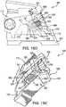
- the upper contact trip 310 is connected to an activation rod 403 ( e.g . FIGS. 15I , 15J and 17A ) which is a linkage which can strike a contact trip actuator 700 ( e.g . FIG. 17A ) which then contacts and activates a tactile switch 800 ( e.g . FIG. 17A ) sending a signal to a microprocessor which runs a machine executable code that turns a motor and drives a nail with a driver blade 54 ( e.g . FIG. 2A ).
- an activation rod 403 e.g . FIGS. 15I , 15J and 17A
- a contact trip actuator 700 e.g . FIG. 17A
- a tactile switch 800 e.g . FIG. 17A
- the fixed nosepiece assembly 300 is adjustable having a depth adjust allowing the user to adjust the firing characteristics of the fixed nosepiece assembly 300.
- a depth adjustment wheel 340 can be moved to affect the position of a depth adjustment rod 350.
- the depth adjustment wheel 340 is a thumbwheel.
- the position of the depth adjustment rod also affects the distance between nose tip 333 and insert tip 355 ( e.g . FIG. 2A ).
- the depth adjustment wheel 340 (or other means of depth adjustment) allows an operator to determine how much of a nail's length can be driven into a workpiece and how much of the nail's length under its nail head can be located at a distance from a workpiece surface.
- depth adjustment can be achieved by changing the relative distance between the upper contact trip 310 and the lower contact trip 320.
- rotating the depth adjustment wheel 340 can move a depth adjustment rod 350 by means of engagement to the depth adjustment rod 350 by machined flats of the depth adjustment wheel 340 into which the depth adjustment rod 350 mates.
- the lower contact trip 320 and the depth adjustment rod 350 can be connected by threads.
- the lower contact trip 320 can not rotate with the depth adjustment rod 350 which forces the lower contact trip 320 to move axially with respect to the depth adjustment rod 350.
- the range of adjustment can be a value in a range of from no adjustment ( i.e . zero (0) mm) to 13.5 mm or greater.
- the range of depth adjustment can be limited by a roll pin (not shown) assembled with relation to the lower contact trip 320 and the front face of the depth adjustment wheel 340.
- the roll pin can be set to prevent the unscrewing of the depth adjustment rod 350 from the lower contact trip 320.
- Numeric values and ranges herein also are intended to have associated with them a tolerance and to account for variances of design and manufacturing.
- a number can include values "about” that number.
- a value X is also intended to be understood as “about X”.
- a range of Y-Z is also intended to be understood as within a range of from “about Y-about Z”.
- significant digits disclosed for a number are not intended to make the number an exact limiting value. Variance and tolerance is inherent in mechanical design and the numbers disclosed herein are intended to be construed to allow for such factors (in non-limiting e.g ., ⁇ 10 percent of a given value).
- the claims are to be broadly construed in their recitations of numbers and ranges.
- the lower contact trip and upper contact trip can move in coordination with each other.
- the lower contact trip 320 can move independently of the upper contact trip 310.
- a contact trip spring 330 can be used.
- a detenting feeling can be provided to the operator moving the depth adjustment wheel 340 by using one or more indexing bolts which can slide on a contact face of the upper contact trip 310 and optionally using two cold formed pockets that change the length of the spring every 180 degrees.
- using the depth adjustment wheel 340 allows for the movement of the lower contact trip 320 independent of the location of the upper contact trip 310.
- the magazine 100 is adapted to hold a means for releasing (or decoupling, or disconnecting) the fixed nosepiece 300 from the magazine 100.
- the means can be at least a magazine screw 337 which can be a captive screw.
- the magazine screw 337 can be screwed to couple the fixed nosepiece assembly 300 to the magazine 100, or unscrewed to decouple the magazine 100 from the fixed nosepiece assembly 300.
- one or more of a magazine screw 337 can be used to fix the nosepiece assembly 300 to the magazine 100.
- the depth to which the depth adjustment rod can be moved is a value from 0 mm to 13.5 mm.
- one or more of the magazine screw 337 can be used to reversibly mate the nose end 102 of the magazine 100 captive to the fixed nosepiece assembly 300.
- the magazine screw 337 can have a variety of screw heads.
- the magazine screw 337 can be a captive screw.
- the magazine screw 337 can be different from a nosepiece insert screw 401 ( e.g . FIG. 2A ).
- Means for releasing the fixed nosepiece 300 from the magazine 100 can be as non-limiting examples a wrench, a screwdriver, an Allen wrench 600 ( FIG. 2 ), or another device capable of loosening a fastener.
- Types of fasteners for fixing nosepiece 300 to the magazine 100 can be as non-limiting examples: a screw, a nail, a nut, a bolt or a reversible fastener.
- the exemplary wrench, screwdriver, or Allen wrench 600 can be adapted to fit with, turn (screw and unscrew; tighten or loosen) magazine screw 337.
- the magazine screw 337 can have a head adapted for an operator to turn manually by use of an operator's fingers.
- a butterfly head screw or folding butterfly head screw can be used, as well as other heads which allow for turning by fingers.
- This disclosure is to be broadly construed regarding the means for fixing or releasing the fixed nosepiece 300 from the magazine 100.
- the fixed nosepiece assembly 300 can fit with the magazine 100 by a magazine interface 380.
- the nosepiece has a sensor which indicates when the fixed nosepiece assembly 300 is not properly or completely screwed into or connected to the magazine 100. This feature can reduce misfiring or bending of nails upon driving.
- the sensor for indicating when the fixed nosepiece assembly 300 is not properly or completely screwed into or connected to the magazine 100 is installed in the magazine 100 or the casing 4.
- the sensor can also have a number of pieces with at least one placed in a nosepiece 12 and optionally another placed elsewhere, such as in the magazine 100 and/or the casing 4.
- the magazine 100 can have a sensor which indicates the number of nails remaining to be fired. In another embodiment, the magazine 100 can have a sensor which indicates the number of nails in the magazine 100. In another embodiment, the magazine 100 can have a sensor which indicates when the magazine has less than a set number of nails, or that the magazine is empty.
- the magazine 100 can have a nail length sensor which indicates a length of one or more of a plurality of nails 55 loaded into the magazine 100 and which can provide an input to a microprocessor of nailer 1.
- the microprocessor can execute machine readable code which can adjust the driving energy expended to drive a nail of an indicated length.
- Such an energy control system can extend battery life by controlling the energy expended in driving nails of an indicated length. This can constitute (or be part of) a fastener tool energy control system (e.g. nailer energy control system).
- the magazine 100 achieves a fast, reliable and effective use and reloading of the magazine 100, and of a fastening tool using it (in the FIG. 1 illustration the tool is nailer 1 ).
- the magazine 100 can have a pusher assembly 110 which retracts a pusher 112 ( e.g ., FIG. 14A ) into a pusher recess 171 ( e.g., FIG. 14A ) which removes the pusher 112 from obstructing a nail track 111 for movement of loaded fasteners or for feeding new fasteners into the magazine 100.
- the pusher assembly 110 can be engaged to move to a position behind the newly inserted plurality of nails 55 and to push the plurality of nails 55 forward for driving by nailer 1.
- the magazine 100 can hold a plurality of nails 55 ( FIG. 6 ) therein.
- a broad variety of fasteners usable with nailers can be used with the magazine 100.
- collated nails can be inserted into the magazine 100 for fastening.
- the pusher assembly 110 can be in a retracted state (e.g . FIG. 10A-H , FIG. 11, FIG. 12 , FIG. 13 and FIG. 14A-B ) allowing for the loading of the plurality of nails 55, or in an engaged state ( e.g . FIG. 6 , FIG. 8 , FIG. 9 , FIG. 14D , FIG. 15 and FIG. 16 ) in which the pusher assembly 110 pushes the plurality of nails 55 as feed to the nosepiece assembly 12 for driving.
- the nails can be fed toward the nose end 102 along the nail track 111 into the nosepiece assembly 12 by the pusher assembly 110 which has the pusher assembly knob 140.
- the pusher 112 of the pusher assembly 110 can be guided in its movement within the magazine 100 and a spring (e.g . a spring 200; see e.g. FIG. 10A ) can apply force to the pusher assembly 110 to feed one or more of the plurality of nails 55 which are guided along the nail track 111 to the nosepiece assembly 12 for fastening.
- a spring e.g . a spring 200; see e.g. FIG. 10A
- FIG. 1 illustrates the nosepiece 12 of exemplary nailer 1 to be a fixed nosepiece assembly 300 (see also FIGS. 2A-2C ).
- An example of the nosepiece 12 of an exemplary nailer 1 having a latched nosepiece assembly 13 is illustrated in FIG. 3 and detailed FIGS. 4-8 .
- a retracted state of the pusher assembly 110 for unloading, loading or reloading can be achieved.
- the pusher assembly 110 has a pusher assembly knob 140 which can be moved by the operator toward the base end 105 of the magazine where it can be reversibly fixed in place, or so as to have a limited range of motion but not fixed in place.
- the pusher assembly knob 140 is connected to the pusher 112. The movement of the pusher assembly knob 140 toward the base end 105 of the magazine where the pusher assembly knob 140 can be reversibly fixed moves the pusher 112 into the pusher recess 171.
- the movement of the pusher 112 into the pusher recess 171 results in a retracted stated of pusher assembly 110.
- the retracted state of the pusher assembly 110 can be maintained by reversibly fixing the pusher assembly knob 140 in place.
- a detent or mechanical means can be provided which prevents the pusher assembly knob 140 and/or the pusher 112 from movement out of the retracted state ( e.g . FIGS. 10A- 12 ) until the operator activates engagement of the pusher assembly 110 to push the plurality of nails 55 toward the nose end 102.
- the pusher assembly 110 can be placed in an engaged state by the movement of the pusher 112 into the nail track 111 and in the direction of loading of fasteners (e.g. nails) to push the plurality of nails 55 toward the nose end 102.
- the pusher assembly knob 140 can be reversibly fixed in place or secured against movement out of a retracted state by a variety of means.
- FIG. 11 shows the pusher assembly knob 140 reversibly fixed in place by a detent 260
- FIG. 12 shows the pusher assembly knob 140 reversibly fixed in place by a spring loaded detent 230
- FIG. 9 shows a detent 156 which is a U-shaped detent and FIG.
- 10B shows the pusher assembly knob 140 reversibly fixed in place by the detent 156.
- the operator can accomplish reloading by using one hand to pull back the pusher assembly 110, reversibly retracting it, and reloading the magazine 100 with fasteners, and then engaging the pusher assembly 110 for fastening operation.
- the magazine can use a push button mechanism (or other detent or latching mechanism) instead of the pusher assembly knob 140 in pusher assembly 110.
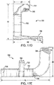
- FIG. 1A is a knob-side view of an exemplary nailer illustrating an embodiment in which the magazine can pivot away from the fixed nosepiece assembly.
- the magazine 100 is pivotably attached to the power tool, for example by coupling member 88 ( FIG. 2 ), or to handle 6, or to base 8.
- the means of attachment adapts the tool so that the nose portion 103 can be moved away from a nosepiece assembly 12.
- FIG. 1A illustrates an example embodiment in which the nosepiece assembly 12 is a fixed nosepiece assembly 300. In an embodiment, the movement away from the nose portion 103 is by a rotational motion. This feature allows for easy removal of misfired nails from the nosepiece assembly 12, ready maintenance and ease of operation.
- unscrewing one or more of a magazine screw 337 can release the magazine 100 from attachment to the fixed nosepiece assembly 300 such that the nose portion 103 can be rotationally moved away from the fixed nosepiece assembly 300 as shown in FIG. 1A by moving the magazine 100 to for example positions 100' and 100".
- Positions 100' and 100" are non-limiting examples of possible locations of the movement of the magazine 100.
- the magazine 100 can be attached to nailer 1 to allow for a movement of the magazine 100 which is other than radial motion.
- Like reference numbers in FIG. 1 identify like elements in FIG. 1A .
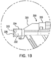
- FIG. 1B is a knob-side view of an exemplary nailer illustrating a detail of a nosepiece assembly 12 having a nose cover 334.
- FIG. 1B illustrates an embodiment in which nose 332 can be covered by a nose cover 334 which has a no-mar pad 335. In an embodiment, the no-mar pad 335 covers the nose tip 333.
- Like reference numbers in FIG. 1 identify like elements in FIG. 1B .
- FIG. 2 is a side view of exemplary nailer 1 having a magazine 100 and viewed from a nail-side 58.
- Allen wrench 600 is illustrated as reversibly secured to the magazine 100.
- Like reference numbers in FIG. 1 identify like elements in FIG. 2 .
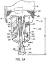
- FIG. 2A is a detail view of the fixed nosepiece assembly 300.
- nosepiece insert 410 having nose 400 with insert tip 355 is inserted into the fixed nosepiece assembly 300.
- nosepiece insert 410 is configured such that a driver blade 54 overlaps at least a portion of a blade guide 415 which optionally can extend under a nose plate 331. The overlap of blade guide 415 by driver blade 54 is optional.
- Blade guide 415 is an optional element of the nosepiece insert 410. In an embodiment, blade guide 415 is not required in the nosepiece insert 410 and can be absent from the nosepiece insert 410. Nose 332 is also illustrated.
- Nosepiece insert 410 can be secured to the fixed nosepiece assembly 300 by one or more of a nosepiece insert screw 401 through a respective insert screw hole 422.
- the nosepiece insert 410 can be investment cast.
- nosepiece insert 410 can be made of a light weight material such as aluminum.
- the nosepiece insert 410 can be investment cast steel.
- the insert can be made at least in part from 8620 carbonized steel, which can optionally be investment cast 8620 carbonized steel.
- the nosepiece insert 410 is joined to the fixed nosepiece assembly 300 by a nail guide insert screw 421 through a rear mount screw hole 417.
- one or more prongs 437 respectively having a screw hole 336 for the magazine screw 337 can be used.
- the nosepiece insert 410 accommodates at least one or more prongs 437.
- FIG. 2A also illustrates a nose plate 331 having a switch activation rod hole 402 through which an activation rod 403 ( e.g . FIG. 15I ) passes. Housing 4 is shown in conjunction with the nose plate 331.
- FIG. 2B is a detailed view of a nosepiece insert 410 viewed from the channel side 412.
- FIG. 2B illustrates nosepiece insert 410 which has a channel side 412 with a nose 400 and insert tip 355.
- the channel side 412 has a blade guide 415 and a nail stop 420.
- the nail stop 420 can be in line with said plurality of nails ( FIG. 2C1 ).
- angle G can be 14 degrees.
- the nail stop 420 having nail stop centerline 427 ( FIG. 2B ) is offset from the insert centerline 423 which achieves the receipt of nails to the nail stop 420 in a configuration in which the longitudinal axis 1127 of the plurality of nails 55 ( FIG. 2C2A ) is collinear (or parallel in alignment) with the longitudinal centerline 1027 of the nail track 111.
- the nosepiece insert 410 can also have a rear mount screw hole 417 and one or more of an interface seat 425.
- FIG. 2B also illustrates the insert screw hole 422 which can secure nosepiece insert 410 into the fixed nosepiece assembly 300.
- nail stop 420 can have a dimension such that a nail will not have contact with the nail stop 420 after 10 percent of the length of the nail has been driven. For example a 90 mm nail would not be in contact with nail stop 420 after 9 mm of the nail has been driven.
- the nail stop 420 length can be set to 10 percent of the length of the loaded nail 53 ( e.g . FIG. 2E ) to be driven. In another embodiment, the nail stop 420 length is 25 percent the length of the nail. In yet another embodiment the nail stop 420 is a value in a range of from 10 percent to 90 percent of the length of the nail, for example 15 percent or 33 percent, or 50 percent.
- the nail stop 420 length can broadly vary in design.
- An embodiment has a nail stop which is shorter in length than the length of a loaded nail (e.g. loaded nail 53; or a nail of the plurality of nails 55 ) to be driven.
- the magazine can be used with nails having different lengths and the nail stop 420 can be shorter then the length of the shortest nail used with the magazine of such embodiment.
- the magazine 100 and the nosepiece assembly 12 can adapted for a collation angle of a plurality of nails 55 which is greater than the angle of the magazine.
- a nail channel 352 is formed when the nosepiece insert 410 is mated with the nose end 102 of the magazine 100 ( e.g . FIG. 2B and FIG. 2D ).
- the formation of the nail channel 352 provides a generally cylindrical path for a nail which is being driven.
- the nail channel has an inner circumference.
- about 50 percent of the inner circumference can be provided by the nosepiece insert 410 and about 50 percent of the inner circumference is provided by the nose end 102.
- Broad variance can be used regarding which pieces provide which percentages of the inner circumference of the nail channel 352. This disclosure should be broadly construed in this regard.
- nosepiece insert 410 can constitute 50 percent of the inner circumference of nail channel 352. In another embodiment nosepiece insert 410 can constitute less than 50 percent of the inner circumference of nail channel 352. In another embodiment nosepiece insert 410 can constitute greater than 50 percent of the inner circumference of nail channel 352.
- FIG. 2B also illustrates insert centerline 423 and nailer 1 channel centerline 429 ( FIG. 2C2A ) perpendicular thereto. As illustrated in FIG. 1A the fixed nosepiece 300 mates with the nose end 102 of the magazine 100. When nosepiece 300 and the nose end 102 are coupled, channel centerline 429 can be collinear or parallel with nailer 1 centerline 1029.
- FIG. 2C1 is a detailed view of a nosepiece insert section 2C1 of FIG. 2B.
- FIG. 2C1 illustrates a cross-sectional detail of the nail stop 420 which is offset from the insert centerline 423 ( FIG. 2 ).
- the location of the nail stop 420 can be set such that a portion of a nail can contact the nail stop 420.
- the location of the nail stop 420 to achieve this orientation can be dependent upon the orientation of the magazine 100.
- Nail stop centerline 427 can be offset in FIG. 2C1 at an angle G measured from nailer 1 channel centerline 429 ( FIG. 2C2A ).
- FIG. 2C2 is a detailed view of a nosepiece insert having nail stop 420 offset at an angle G measured from the channel centerline 429 ( e.g . FIG. 2B ).
- angle G aligns the longitudinal centerline 1027 of the nail track 111 with the centerline 1127 of the plurality of nails 55 and also nail stop centerline 427.
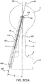
- FIG. 2C2A is a perspective view illustrating the alignment of an embodiment of a nailer 1, a magazine 100, a plurality of nails 55 and a nail stop 420.
- FIG. 2C2A illustrates the nail stop 420, the nail stop centerline 427, a longitudinal centerline 927 of the magazine 100, a longitudinal centerline 1027 of the nail track 111, a longitudinal centerline 1127 of the plurality of nails 55 and a longitudinal centerline 1227 of the nailer 1.
- FIG. 2C2A illustrates that in an embodiment having fixed nosepiece 300 having nosepiece insert 410 is mated with the nose end 102 channel centerline 429 can be collinear with nail 1 centerline 1029.
- Like reference numbers in FIG. 1 identify like elements in FIG. 2C2A .
- the magazine 100 can have its longitudinal centerline 927 offset from a longitudinal centerline 1227 of nailer 1 by an angle G. Angle G can be 14 degrees.
- nail stop centerline 427 can be collinear with a longitudinal centerline 927 of the magazine 100.
- longitudinal centerline 927 of the magazine 100 can be collinear with a longitudinal centerline 1027 of the nail track 111, as well as collinear with a nail stop centerline 427.
- Longitudinal centerline 1127 of the plurality of nails 55 can be collinear with nail stop centerline 427.
- a wide range of angles and orientations for the nail stop 420 can be used.
- FIG. 2D is a detailed view of the nosepiece insert 410 viewed from the fitting side 430.
- the fitting side 430 can have a magnet stop 435 and a magnet seat 440 which are adapted for the mounting of a magnet 445.
- Magnet 445 can be mounted on the fitting side 430 by a variety of means including frictional fit (e.g . in which the magnet is fit between the magnet stop 435 and the magnet seat 440 ), by magnetic attraction of magnet 445 to the insert 410, structural fit, by adhesive, fastener, or other mounting and/or fastening means.
- at least a portion of insert 410 can have magnetic properties.
- a magnetic portion of insert 410 can be used to guide driver blade 54.
- Like reference numbers in FIG. 2B identify like elements in FIG. 2D .
- the fitting side 430 can have a rear mount 450 and a rear mount screw hole 417 to receive a screw to secure nosepiece insert 410 to the fixed nosepiece assembly 300.
- the fitting side 430 can also have a mount 455 to receive a screw to secure nosepiece insert 410 to the fixed nosepiece assembly 300.
- the fitting side 430 can have lower trip seat 460 which fits into a portion of nosepiece assembly 300.
- Like reference numbers in FIG. 2B identify like elements in FIG. 2D .
- the nosepiece insert 410 and the nose end 102 of the magazine 100 can be reversibly fit together by a fastening means.
- at least a magazine screw 337 can be turned to reversibly fit nosepiece insert 410 and the nose end 102 together.
- the nail channel 352 can be formed by fitting nosepiece insert 410 and the nose end 102 together.
- Like reference numbers in FIG. 2A identify like elements in FIG. 2E .
- FIG. 2E is a detailed view of a fixed nosepiece with a nosepiece insert and a mating nose end of a magazine (which can mate as illustrated in FIG. 1A ).
- FIG. 2E is a detailed view of the nosepiece assembly 300 from the channel side 412 which mates with the nose end 102 of the magazine 100. See FIG. 1A for an example of a motion of the magazine 100 which can achieve mating of the nose end 102 and the magazine 100.
- FIG. 2E detail A illustrates a detail of the nosepiece insert 410 from the channel side 412.
- the nosepiece insert 410 has the rear mount screw hole 417 for the nail guide insert screw 421.
- the nail guide insert screw 421 can be a rear mounted or front mounted screw.
- Nosepiece insert 410 can also have a blade guide 415 and nail stop 420.
- Nosepiece insert 410 can be fit to nosepiece assembly 300 and can have an interface seat 425.
- Nosepiece insert 410 can also have a nosepiece insert screw hole 422 and a magazine screw hole 336.
- insert screw 401 for mounting the nosepiece insert 410 to the fixed nosepiece assembly 300 can be a rear mounted screw or a front mounted screw.
- Like reference numbers in FIG. 2A identify like elements in FIG. 2E .
- FIG. 2E detail B is a front detail of the face of the nose end 102 having nose end front side 360.
- the nose end 102 can have a nose end front face 359 which fits with channel side 412.
- the nose end 102 can have a nail track exit 353.
- a loaded nail 53 is illustrated exiting nail track exit 353.
- FIG. 2E detail B also illustrates screw hole 357 for magazine screw 337.
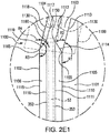
- FIG. 2E1 is a detailed view of a nail feed funnel 1100.
- nail feed funnel 1100 can have an opening from which the loaded nail 53 emerges from nail track exit 353 of the magazine 100 and is fed into nail channel 352.
- Nail feed funnel 1100 can have one or more feed surfaces ( e.g . 1103 and 1104 ) along which a nail head 1130 can slide.
- a feed plane 1199 can be coplanar with one or more feed surfaces.
- a first feed surface 1103 and a second feed surface 1104 are coplanar.
- a feed plane 1199 is illustrated as also coplanar with 1103 and 1104.
- the nail feed funnel 1100 can have a first feed surface 1103 and a second feed surface 1104 and can be at least a part of a transition portion from which a nail 53 emerges from nail track exit 353 and enters into nail channel 352.
- FIG. 2E1 illustrates the nail feed funnel 1100 having first feed guide 1101 and second feed guide 1102.
- First feed guide 1101 can have inner edge 1111 and end edge 1110, as well as track edge 1112 and top edge 1113.
- Track edge 1112 and top edge 1113 can be connected by funnel edge 1114 which can extend between inner funnel point 1150 and outer funnel point 1155.
- Second feed guide 1102 can have inner edge 1116 and end edge 1115, as well as track edge 1117 and top edge 1118.
- Track edge 1117 and top edge 1118 can be connected by funnel edge 1119 which can extend between inner funnel point 1160 and outer funnel point 1165.
- a nail feed funnel 1100 can be constructed of a wide range of geometries and contain a broad variety of elements.
- the shape of a nail feed funnel 1100 can vary broadly.
- the nail feed funnel 1100 can have one or more of a curved surface, a flat surface, a notched surface, an angled surface, a textured surface, a coated surface, a non-stick surface or other surface type.
- Nail feed funnel 1100 can have two or more of the same type of surface, or a combination of surface types.
- first feed surface 1103 and a second feed surface 1104 each have a generally flat surface and are generally planar with one another.
- first feed surface 1103 and second feed surface 1104 can be ridged or notched to fit with an outer diameter of a nail head.
- first head guide surface 1105 and second head guide surface 1106 are illustrated in FIG. 2E1 .
- Each of first head guide surface 1105 and second head guide surface 1106 can be a surface along which at least a portion of a nail head can slide or be guided as a nail is driven.
- First head guide surface 1105 and second head guide surface 1106 can be each generally flat in shape.
- first head guide surface 1105 and second head guide surface 1106 can be ridged, or notched, or otherwise shaped, to fit with an outer circumference of a nail head.
- First head guide surface 1105 and second head guide surface 1106 can have similar or different shapes and surfaces.
- the funnel can have an angle R1.
- Angle R1 can be the angle between end edge 1110 and top edge 1113. This angle can have a wide range of values. Angle R1 for example can be a value in a range of from less than 90° to 175°. In an embodiment, Angle R1 can be 90°. In another embodiment angle R1 can be 130°. In another embodiment angle R1 can be 145°. FIG. 2E1 illustrates angle R1 can be 165°. Angle R3 can be the angle between end edge 1115 and top edge 1118. Similarly, angle R3 can also have a values disclosed herein for angle R1 ( e.g. a value in a range of from less than 90° to 175°, 130°, 145°, or 165°). FIG. 2E1 illustrates angle R3 can be 165°.
- the funnel can have an angle R2.
- Angle R2 can be the angle between funnel edge 1114 and top edge 1113. This angle can have a wide range of values. Angle R2 for example can be a value in a range of from less than 90° to greater than 150°. In an embodiment, Angle R2 can be 90°. In another embodiment R2 can be 60°. In another embodiment R2 can be 30°. FIG. 2E1 illustrates angle R2 can be 35°. Angle R4 can be the angle between funnel edge 1119 and top edge 1118. Similarly, angle R4 can have the values disclosed herein for angle R2 ( e.g . a value in a range of from less than 90° to greater than 150°, 90°, 60°, 35° or 30°). FIG. 2E1 illustrates angle R4 can be 35°.
- FIG. 2E1 illustrates a nail feed funnel 1100 which is a ramped nail feed funnel in which R1 can have a value of 165° and R3 can have a value of 165°.
- the a ramped feed funnel having an angle R1 and/or an angle R3 has funnel surfaces and features which can be inspected by automated inspection equipment, e.g . optical, or mechanical inspection.
- the exit of a nail to be driven from nail track exit 353 via nail feed funnel 1100 can position the nail head in relation to driver blade 54 to reduce skipping, buckling and bending of loaded nail 53 when it is driven.
- the nail head is located less than 30 mm ( e.g . 20 mm or 15 mm), from the closest portion of driver blade 54. In another embodiment, the nail head is located 10 mm or less, or 5 mm or less, from the closest portion of driver blade 54.
- the nail feed funnel 1100 can be cast of a metal.
- the nail feed funnel 1100 can be cast of a light weight material such as aluminum, or the nail feed funnel 1100 can be investment cast steel.
- the nail feed funnel 1100 can be 8620 carbonized steel.
- the disclosure herein also encompasses a means for guiding a nail for and during driving in nailer 1, which in an example uses a fixed nosepiece 300 having a nosepiece insert 410 in a nosepiece 12.
- Such means also can include a broad variety of nail stops, channel designs having geometries providing equivalent control to nail movement as the nosepiece insert 410, variations on the nosepiece 12 which have one piece nail channels and which incorporate aspects of the nose end 102 of magazine 100.
- means for guiding a nails for and during driving in nailer 1 can include a broad variety of funnel designs and mechanisms for providing a nail 57 in an orientation for proper driving by a driver blade 54.
- Such mean can include a funnel which is contained within the nosepiece or which is part of a nosepiece insert.
- This disclosure also encompasses the methods for feeding a nail 57 to a driver blade 54 using the elements, equivalents and means disclosed herein.
- FIG. 3 is a side view of another embodiment of exemplary nailer 1 viewed from the knob-side 90 and having a magazine 100 showing the pusher assembly 110 having a pusher assembly knob 140.
- the nosepiece assembly 12 is a latched nosepiece assembly 13.
- the magazine 100 is coupled to the housing 4 and coupled to the base 8 of the handle 6 by bracket 11.
- Like reference numbers in FIG. 1 identify like elements in FIG. 3 .
- FIG. 4 is a perspective view of latched nosepiece assembly 13 of nailer 1 having a latch mechanism 14 and which can be used with the magazine 100.
- Latched nosepiece assembly 13 has a nosepiece 28 which is mounted to a backbone structure of housing 4 ( FIG. 1 ).
- Nosepiece 28 has a pair of hooks 32 that extend therefrom in a direction away from the magazine 100.
- a nose cover 34 can be pivotally mounted to the nosepiece 28 near an end 30 by a pin connection 36 extending between a pair of lugs 37.
- Nosepiece 28 further has a groove 50 and the nose cover 34 has a cam portion 56.
- the nose cover 34 can extend along the length of the nosepiece 28 between the hooks 32.
- the nose cover 34 has a rib 38 that extends along its length. Rib 38 can be used to provide strength to the nose cover 34 and a line-of-sight for the operator of the nailer 1 to align the nails.
- the nosepiece 28 and nose cover 34 define a channel 52 ( e.g . FIG. 6 ) which is a passage through which a nail can pass.
- FIG. 4 also illustrates an embodiment having a tip portion 39 which can contact a workpiece.
- the latch mechanism 14 is mounted to the nose cover 34 and has a latch tab 40 and a latch wire 42.
- the latch mechanism 14 can be used to lock and unlock the nose cover 34 to and from nosepiece 28.
- the latch tab 40 is pivotally connected to the nose cover 34 at pin 44.
- Latch wire 42 is pivotally coupled to latch tab 40 at slots 46.
- the latch wire 42 can be formed such that a center portion 49 of latch wire 42 has a hump portion 51 sized to fit over the rib 38 ( FIG. 2 ).
- the latch wire 42 has a pair of parallel arms 48 which can be perpendicular to a center portion 49 of latch wire 42. Various shapes of the arms 48 can be employed.
- the latch wire can have at least an arm 43 which can have a sinusoidal, or "S" shape as illustrated in e.g . FIGS. 4 and 6 .
- FIG. 5 is a rear perspective view of a latch wire and latch tab used with the latch mechanism 14.
- the latch wire 42 is pivotally coupled to the latch tab 40 at slots 46. Slots 46 can be sized to allow for securing and release of the latch wire 42 by the operation of latch tab 40.
- Like reference numbers in FIG. 4 identify like elements in FIG. 5 .
- the latch wire 42 is locked firmly within the hooks 32 of the nosepiece 28.
- the center portion 49 in turn presses firmly down upon the nose cover 34 on each side of the rib 38. This ensures that nose cover 34 is tightly engaged to nosepiece 28.
- the latch tab 40 can be urged away from nose cover 34. This in turn disengages the latch wire 42 from the hooks 32, thus allowing the nose cover 34 to pivot about pin connection 36 away from the nosepiece 28. In the unlocked position, an operator can then clear any nail jams within the nosepiece assembly 12.
- FIG. 6 is a side view of the latched nosepiece assembly 13 and the nose portion 103 of the magazine 100 having the nose end 102.
- FIG. 6 illustrates a driver blade 54 and the pusher assembly 110 having the pusher 112 used with the magazine 100 of nailer 1 and pushing on a nail 57 of the plurality of nails 55.
- the nosepiece 28 has a groove 50 formed therein that cooperates with the nose cover 34 to form a channel 52 (channel is generally cylindrical when the nose cover 34 is in its locked position) ( e.g ., FIG. 7 and FIG. 8 ).
- the channel 52 is sized to receive a loaded nail 53 pushed into it from the magazine 100.
- the driver blade 54 extends from the housing 4 into channel 52.
- the driver blade 54 is driven by the motor and nail driver mechanism (not shown) and engages the head of the loaded nail 53 to drive the loaded nail 53 through the nosepiece 28 and out of the nailer 1.
- the driver blade is a crescent shaped driver blade.
- nose cover 34 When the nose cover 34 is in its unlocked position (shown in dashed lines in FIG. 6 ), to prevent escape of driver blade 54 from the nosepiece 28, nose cover 34 has a cam portion 56. As the nose cover 34 is moved to its unlocked position, the cam portion 56 engages the driver blade 54, thereby constraining the driver blade 54 to the groove 50 and preventing the driver blade 54 from escaping.
- Like reference numbers in FIG. 4 and FIG. 5 identify like elements in FIG. 6 .
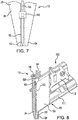
- FIG. 7 illustrates a cross section of channel 52 of latched nosepiece assembly 13 (and a nose-on view of nosepiece 28 ) having a loaded nail 53 in place for driving by driver blade 54.
- FIG. 7 further illustrates end 30 and nose cover 34 of nosepiece 28.
- the nosepiece 28 also includes a nail stop bridge 83 which bridges the channel 52.
- the nail stop bridge 83 or a nail stop, can stop each nail of the plurality of nails 55 as they are pushed by the pusher 112 into channel 52. This assures that the head of the loaded nail 53 within the channel 52 is aligned with the driver blade 54.
- the nail stop bridge 83 also prevents buckling of a loaded nail 53, which can occur as the driver blade 54 strikes the loaded nail 53.
- the nail stop bridge 83 is formed as part of the nosepiece 28 and optionally can be of a single unitary structure.
- FIG. 8 is a side sectional view of the latched nosepiece assembly 13 illustrating a nail stop bridge 83 used.
- channel 52 can be formed from two or more pieces, e.g . nose cover 34 and at least one of groove 50 and nosepiece 28 (and/or nail stop bridge 83 ).
- Nosepiece 28 has a groove 50 ( FIG. 4 ) formed therein which cooperates with the nose cover 34 (when the nose cover 34 is in its locked position).
- the locking of nose cover 34 against groove 50 can form an upper portion of channel 52.
- the driver blade 54 can extend from housing 4 into channel 52.
- the driver blade 54 can engage the head of the loaded nail 53 to drive loaded nail 53.
- Cam 56 prevents escape of driver blade 54 from the nosepiece 28.
- Nosepiece 28 further has a nail stop bridge 83 that bridges the channel 52.
- the nail stop bridge 83 engages each nail of the plurality of nails 55 as they are pushed by the pusher 112 along the nail track 111 of the magazine 100 and into channel 52.
- the tips of the plurality of nails 55 can be supported by the lower liner 95, or a lower support.
- the lower liner 95 forms part of the magazine 100.
- FIG. 9 is a side view of the magazine 100 viewed from the knob-side 90 showing the pusher assembly 110 in an engaged state.
- FIG. 9 illustrates the pusher assembly knob 140 and a partial view of the pusher 112 as seen through the guide path opening 152 of the pusher assembly guide path 150.
- a spring 200 biases the pusher 112 in a direction from the base end 105 to the nose end 102 of the magazine 100.
- the spring 200 is a constant force spring.
- this disclosure is not limited regarding the means of biasing the pusher 112.
- This disclosure is also not limited as to a spring type (or motive force) for biasing the pusher 112.
- the pusher assembly 110 can receive a motive force from a mechanism other than a spring and no spring 200 is used.
- the means to apply motive force on the pusher 112 can vary broadly and this disclosure is to be broadly construed in this regard.
- the pusher assembly guide path 150 has a pusher track nose end 151 which is proximate to the nose portion 103 of the magazine 100 and a pusher track base end 157 which is proximate to base portion 104 of the magazine 100.
- the pusher assembly knob 140 can be moved such that the pusher assembly 110 is in a retracted state.
- the pusher assembly knob 140 can interact with and can be held in place proximate to the pusher track base end 157 by a detent 156 with a detent base end 154.
- the detent base end 154 can have a stop 158 that stops the pusher assembly knob 140 being moved in a manner which can impart unacceptable stress on the pusher assembly 110 when being placed in a retracted stated.
- the stop 158 can prevent mechanical damage to the pusher assembly 110 when an operator moves the pusher assembly knob 140 such that it is engaged with the detent.
- a detent can be an integral portion of a magazine 100 ( e.g . FIGS. 9-10H ).
- the detent can be a separate member interacting with both the magazine 100 and pusher assembly 110.
- the detent base end 154 can be a spring member or a spring biased member that can be deflected when the pusher assembly 110 is being placed in, or moved into, a retracted state.
- the spring member or spring biased member can be deflected in a direction away from the pusher assembly knob 140, or the knob base end 143.
- the detent base end 154 can be moved toward or into the guide frame inside portion 153, e.g. downwardly away from a portion of the pusher assembly knob 140, to allow a portion of assembly knob 140, e.g . the knob base end 143 to move past and optionally latch to the detent base end 154.
- the pusher assembly knob 140 of the pusher assembly 110 is located adjacent to a knob-side of pusher guide frame 159.
- the pusher assembly 110 has a connecting mechanism ( e.g . FIG. 10A ) which is attached to the pusher assembly knob 140 and which is connected to the pusher 112.
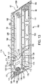
- the pusher guide frame 159 has a guide frame inside portion 153 ( e.g . FIG. 13 ) and a guide frame outside portion 91 ( e.g . FIG. 9 and FIGS. 11- 12 ).
- the nail track 111 is located in the guide frame inside portion 153.
- the nail track 111 extends from the nail feed slot 59 ( e.g . FIGS. 11- 12 ) located at the base end 105 to the nose end 102 of magazine 100 and extends through the guide frame inside portion 153.
- the pusher assembly 110 is configured such that the pusher 112 in both its retracted state and its engaged state is located within the guide frame inside portion 153.
- a plurality of nails 55 can be inserted into the magazine via the nail track 111.
- the plurality of nails 55 can have tips which are supported by the lower liner 95. If the plurality of nails 55 are inserted in the magazine 100 to a location past the pusher 112 in the direction of the nose end 102 the pusher assembly 110 can be released to move and/or can be moved from a retracted state to an engaged state.
- the pusher assembly 110 in the engaged state can push against one of the plurality of nails 55.
- the spring 200 which is biased toward the nose end 102, can impart a force pushing the nails toward the nose end 102 and allowing the nails to move along the nail track 111 toward and for feeding into the nosepiece assembly 12.
- the pusher assembly 110 can move along the upper pusher guide 162 and lower pusher guide 170 ( e.g . FIG. 13 ) and move the plurality of nails 55 along the nail track 111 in a direction away from the magazine base end toward the magazine nose end and push one or more of the plurality of nails 55 into the nosepiece assembly 12 for nailing.
- the pusher assembly 110 is configured such that the pusher 112 can be in a retracted state wherein the pusher 112 is retracted into the pusher recess 171 ( e.g . FIGS. 10B-C , FIG. 13 and FIGS. 14A ) or the pusher 112 can be in an engaged state such that it is located at a position in the nail track 111 ( e.g . FIGS. 15-16 and FIG. 14D ).
- the pusher 112 in an engaged state the pusher 112 has moved out from the pusher recess 171 and in part or in whole into the nail track 111.
- FIG. 9 also illustrates a lockout 500 for prevent or inhibiting actuation a contact trip actuator 700 of nailer 1 when a predetermined number of nails or zero (0) nails are present in the magazine ( e.g . FIGS. 15-15L ).
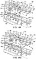
- FIG. 10A is a sectional view of the pusher assembly 110 having the pusher assembly knob 140 moving toward a detent 156.
- a latch pin 147 connects the pusher assembly knob 140 to the pusher 112 and passes through the guide path opening 152 ( e.g . FIG. 9 ).
- the pusher assembly knob 140 has a knob stem 144.
- the knob stem 144 has a cylindrical cavity 136 ( e.g . FIG. 10A1 ) configured to receive a plug stem portion 138 of a plug 137 which has a plug head 146 ( e.g . FIG. 10A1 ).
- the plug 137 has a screw passage 135 ( e.g . FIG. 10A1 ) through which screw 148 passes to secure the knob stem 144 and the plug 137 together.
- the pusher 112 has a pusher assembly spool 142 which has a cylindrical passage 139 through which a portion of the assembly the knob stem 144 can be inserted.
- the spring 200 is illustrated spooled around the pusher assembly spool 142.
- the pusher 112 has a knob connector opening 155 in communication with a cylindrical passage 139.
- the knob connector opening 155 has radial dimensions smaller than the radial dimensions of a plug head 146 of the plug 137.
- the pusher assembly 110 can be assembled by inserting at least in part the knob stem 144 within the pusher assembly spool 142 which has the cylindrical passage 139 through which the knob stem 144 is inserted.
- Plug stem portion 138 of the plug 137 can be inserted through the knob connector opening 155 and at least in part into the cylindrical cavity 136.
- the screw 148 can be screwed through the screw passage 135 at least in part into assembly the knob stem 144 securing the pusher assembly knob 140 and the plug 137 together.
- a washer 161 is placed under a screw head of the screw 148 to reduce undesired screw movement.
- the plug head 146 can have a radial dimension which is larger than a redial dimension of the knob connector opening 155 such that the plug head 146 can not pass through the knob connector opening 155 of the pusher 112.
- the pusher assembly spool 142 has a knob connector opening 155 which has an oval shape, while the cylindrical passage 139 is cylindrical.
- the oval shape of the knob connector opening 155 does not allow the plug head 146 to pass therethrough preventing the plug head 146 from entering into the cylindrical passage 139.
- This disclosure is not limited as to how the plug head 146 is prevented from passing through the knob connector opening 155 and should be broadly construed in this regard.
- An inner diameter of cylindrical passage 139 can be larger than an outer diameter of the knob stem 144 such that the knob stem 144 can be tilted toward the nose end 102 and away from the base end 105 ( e.g . FIG. 10C and FIG. 10D ) such that the pusher assembly knob 140 can engage and disengage from the detent 156.
- the pusher assembly knob 140 having an assembly knob nose end 141 can optionally be mounted upon a spring 210 which is placed between the pusher assembly spool 142 and the pusher assembly knob 140.
- the spring 210 can be a compressive spring.
- the assembly knob stem 144 can be inserted at least in part through a spring passage 212.
- the spring 210 having the spring passage 212 can be used.
- the pusher assembly knob 140 can be moved toward the detent 156 such that the pusher assembly knob base portion 145 passes over the detent 156 and reversibly engages the pusher assembly knob 140 with the detent 156. While reversibly engaged, the pusher assembly knob 140 can be latched by the knob base end 143 to a detent base end 154.
- FIG. 10A also illustrates the stop 158.
- the pusher 112 can be guided by at least one guide ramp into a recess ( e.g . the pusher recess 171 ) while simultaneously the pusher assembly knob 140 is in contact with a detent, e.g . the detent 156.
- a movement of the assembly knob 140 to engage detent 156 can simultaneously cause the pusher 112 to be guided into the pusher recess 171 by a guide ramp ( e.g ., an upper nose prong ramp 164 ( FIG. 14A ), or a ramp 285 ( FIGS. 11 and 12 )) .
- the reverse process can also be executed; the pusher 112 can be guided out of a recess ( e.g . the pusher recess 171 ) by at least one ramp when simultaneously the pusher assembly knob 140 is moved while released from a detent.
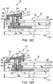
- FIG. 10B is a sectional view of the pusher assembly 110 having a pusher assembly knob 140 reversibly fixed by the detent 156.
- FIG. 10B illustrates the pusher assembly knob 140 reversibly latched onto the detent 156 by the latching of the knob base end 143 over the detent base end 154.
- Like reference numbers in FIG. 10A identify like elements in FIG. 10B .
- FIG. 10C is a sectional view of the pusher assembly 110 having the pusher assembly knob 140 experiencing or being pushed by both a lateral force toward the nose end 102 and a downward force toward the magazine body 106, thereby imparting a radial force on the nose side 213 of the spring 210.
- This compression of the nose side 213 of the spring 210 tilts a portion of the knob stem 144 toward the nose end 102. This tilting raises the knob base end 143 to allow it to move over the detent base end 154 toward the nose end 102.
- Like reference numbers in FIG. 10A identify like elements in FIG. 10C .
- FIG. 10D is a sectional view of the pusher assembly 110 having a pusher assembly knob 140 which has been released from the detent 156 and which is moving away from the detent 156 toward the nose end 102 and into the nail track 111.
- the pusher assembly 110 also moves toward the nose end 102 and the pusher assembly 110 is disengaged from the detent 156.
- the pusher assembly knob 140 can return to its not tilted configuration as shown in FIG. 10A .
- Like reference numbers in FIG. 10A identify like elements in FIG. 10D .
- FIG. 10E is a sectional view of the pusher assembly 110 having the pusher assembly knob 140 moving toward the detent 156.
- the embodiment of the pusher assembly 110 is a spring-free pusher assembly.
- spring-free means that a spring is not used at a location between the pusher assembly spool 142 and the pusher assembly knob 140.
- a spring analogous to the spring 210 of FIG. 10A is not used.
- FIG. 10E illustrates an embodiment in which a latch pin 147 connects the pusher assembly knob 140 to the pusher 112 and passes through the guide path opening 152 ( e.g. FIG. 9 ).
- the forces provided by the spring 200 and the reversible fitting of the knob base end 143 with the detent base end 154 achieves the reversible retraction of the pusher assembly 110.
- Like reference numbers in FIG. 10A identify like elements in FIG. 10E .
- movement of the pusher assembly knob 140 toward the detent 156 allows the pusher 112 to be guided by a ramp 199 into the pusher recess 171 out of the nail track 111.
- the movement of the pusher assembly knob 140 away from the detent 156 allows the pusher 112 to be guided by the ramp 199 out of the pusher recess 171 into the nail track 111.
- FIG. 10F is a sectional view of with a spring-free pusher assembly reversibly fixed by a detent. Like reference numbers in FIG. 10E identify like elements in FIG. 10F .
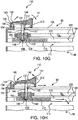
- FIG. 10G is a sectional view of a pusher assembly having a spring-free pusher assembly which is being pushed to release it from a detent.
- movement of the pusher assembly knob 140, which is spring-free, in a manner to engage the detent 156 can achieve retraction of the pusher 112.
- Like reference numbers in FIG. 10E identify like elements in FIG. 10G .
- FIG. 10H is a sectional view of a pusher assembly having a spring-free pusher assembly released from a detent and moving away from the detent, then into the nail track 111.
- Like reference numbers in FIG. 10E identify like elements in FIG. 10H .
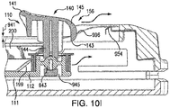
- FIG. 10I is a sectional view of an embodiment of the pusher assembly in which the pusher assembly knob 140 has a pivot stem 944 and which is moving toward the detent 156.
- the pivot stem 944 is pivotably attached to a pivot 943.
- the pivot 943 can be located in a pivot chamber 945 of the pusher assembly 110.
- the pusher assembly knob 140 can have the pusher assembly knob base portion 145 which has the knob base end 143.
- FIG. 10I also shows a spring latch 954 of the detent 156.
- the movement of the pusher assembly 110 toward the spring latch 954 reversibly moves the pusher assembly 110 into its retracted position.
- the latching of the pusher assembly knob 140 to the spring latch 954 achieves the reversible retraction of the pusher assembly 110.
- the pusher assembly knob 140 can have the pusher assembly knob base portion 145 which has the knob base end 143 that can be reversibly latched to the spring latch 954.
- Like reference numbers in FIG. 10A identify like elements in FIG. 10I .
- movement of the pusher assembly knob 140 toward the detent 156 allows the pusher 112 to be guided by the ramp 199 at least in part, or wholly, into the pusher recess 171 out of the nail track 111.
- the movement of the pusher assembly knob 140 away from the detent 156 allows the pusher 112 to be guided by the ramp 199 out of the pusher recess 171 and into the nail track 111 ( FIG. 10J ).
- a knob ramp 996 can be used to guide the pusher assembly knob 140 toward the spring latch 954 to facilitate latching.
- the pusher assembly knob 140 when the pusher assembly 110 is not retracted and the pusher 112 is engaged in the nail track 111, the pusher assembly knob 140 can be set to have a knob clearance 941 which reduces and/or eliminates friction between the assembly knob 140 and the magazine body 106.
- the knob clearance 941 can have a distance in a range such as 0.001 mm or greater, for example: 0.05 mm, 0.075 mm, 1.0 mm, 1.25 mm, 1.5 mm, 2.0 mm, 2.5 mm, 3.0 mm, 5 mm, 10 mm, or greater.
- FIG. 10J shows the pusher 112 in its retracted state and the pusher assembly knob 140 reversibly latched to the spring latch 954.
- the spring latch 954 can be made at least in part of formed sheet metal.
- the spring latch 954 can be made in part or in whole from a broad variety of materials such as metals, formed metals, plastics, polymers, cured resins or any other material with flexibility and durability properties to be able to function as the spring latch 954 for the pusher assembly knob 140.
- Like reference numbers in FIG. 10I identify like elements in FIG. 10J .
- the spring latch 954 can be formed to have a spring action when experiencing force from the pusher assembly knob 140, or other source. Force sufficient to cause a spring action of the spring latch 954 can be imparted by the pusher assembly knob 140 when the pusher assembly knob 140 is being latched to the spring latch 954, or when the pusher assembly knob 140 is pivoted to unlatch the pusher assembly knob 140 from the spring latch 954. In an embodiment, when the pusher assembly knob 140 is being latched, the force against the detent from at least a portion of the pusher assembly knob such as the knob base portion 145 and/or the knob base end 143 can cause a spring action of spring latch 954 to occur.
- the pusher assembly knob 140 can be unlatched by a release force of 3 lbf or less which is applied in the direction of arrow K to at least a portion of the pusher assembly knob 140, such as the assembly knob nose end 141.
- FIG. 10J shows the direction of arrow K can be along a push axis 1040 which can be perpendicular to the longitudinal centerline 1027.
- the pusher assembly knob 140 can be unlatched by a release force applied in the direction of arrow K2 ( FIG. 10J ) of 2.25 lbf or less.
- the release force of 2.25 lbf or less can be applied to the assembly knob nose end 141 at an angle 1043 in a range of from 15° to 90°, for example: 80°, or 66°, or 45° or 33°, or 25°.
- Example 1 the reversible latching of the pusher assembly knob 140 to a portion of detent 156 allows for a release and/or unlatching by a force of 3 lbf or less applied at any of a wide range of angles to various portions of the pusher assembly knob 140.
- the reversible latching of the pusher assembly knob 140 to the spring latch 954 allows for a release and/or unlatching by a force of 3 lbf or less applied at any of a wide range of angles to various portions of the pusher assembly knob 140.
- FIG. 10K shows an embodiment in which the pusher assembly knob 140 can be unlatched from the spring latch 954 by applying a release force to the pusher assembly knob 140, for example at the assembly knob nose end 141. Applying a release force to the pusher assembly knob 140 can pivot the pusher assembly knob 140 and the pivot stem 944 about the pivot 943 which can disengage the knob base end 143 of the pusher assembly knob base portion 145 from the spring latch 954.
- Like reference numbers in FIG. 10I identify like elements in FIG. 10K .
- the pusher assembly knob 140 can have a pivoting stem member, such as pivot stem 944 or knob stem 144, which in conjunction with detent 156 can achieve a quick release mechanism which allows an operator to unlatch a latched pusher assembly knob by applying a force of 15 lbf or less, for example: 10 lbf, or 6 lbf, or 5 lbf, or 3 lbf, or 2.75 lbf, or 2.5 lbf, or 2.25 lbf, or 2.0 lbf, or 1.75 lbf, or 1.5 lbf, or 1.25 lbf, or 1.0 lbf, or 0.75 lbf, or 0.5 lbf, or 0.25 lbf.
- a pivoting stem member such as pivot stem 944 or knob stem 144
- the detent base end 154 or the spring latch 954 can be used in the quick release mechanism.
- the spring 200 can also be a member of the quick release mechanism and can impart a bias upon the pusher assembly which can move the pusher assembly 110 into an engaged state automatically once the pusher assembly knob 140 is unlatched.
- the spring 200 imparts a bias upon the pusher assembly which contributes to the unlatching of the pusher assembly knob 140 when an operator initiates an unlatching movement of the pusher assembly knob 140.
- the bias of spring 200 imparted upon the pusher assembly can be in a direction generally toward the nose end 102 of the magazine 100.
- a retracted pusher assembly can move the pusher 112 automatically under a bias imparted by spring 200 out of the pusher recess 171 and into the nail track 111 to achieve an engaged state of the pusher assembly 110 when the pusher assembly knob 140 is unlatched.
- unlatching the pusher assembly knob 140 and/or movement of the pusher 112 out of the pusher recess 171 and into the nail track 111 to achieve an engaged state can be manually achieved by an operator.
- the transition of the pusher assembly 110 form a retracted and latched state to an engaged state in which the pusher 112 moves from the pusher recess 171 into nail track 111 can be a spring assisted manual action in which both a force provided by an operator and a bias imparted by spring 200 act together achieve the engaged state of the pusher assembly 110.
- FIG. 11 is a sectional view of another embodiment of a pusher assembly which can be used with the magazine 100 and which can be fixed by engagement with another embodiment of a detent.
- FIG. 11 illustrates, a pusher assembly 215 having a knob 216 having a notch 217 in a fixed position by its engagement with the detent 260.
- the notch 217 can be configured to mate with the detent 260. As illustrated, the knob 216 is in a fixed position and reversibly mated with the detent 260. In this configuration, a pusher 225 is retracted into a recess 280. The pusher 225 is maintained in the recess 280 when the pusher assembly 215 is in a retracted state. The retraction of the pusher 225 is achieved by the bias of a spring 220 pushing a retracting member 229 away from the nail track 111. The retracting member 229 is connected to the pusher 225 by the pusher connecting member 227. The pusher 225 can be maintained in a retracted state by the bias of the spring 220 against the retracting member 229.
- a plurality of nails 55 can be loaded into the magazine 100 through a nail feed slot 59.
- the pusher assembly 215 can be transitioned from a retracted state to an engaged state by an operator pressing the knob 216 in a fashion that imparts force upon the knob 216 in a direction laterally toward the nose end 102 and also in a direction toward the magazine body 106.
- This type of pressing motion can impart a radial movement tilting the knob 216 which can raise the notch 217 and disengage the notch 217 from the detent 260.
- the pusher assembly 215 can move away from the base end 105 and toward the nose end 102 of the magazine.
- a ramp 285 can connect the recess 280 with the nail track 111.
- the detent e.g ., 260
- the detent can be a raised feature of the magazine housing.
- the spring 200 biases the pusher 225 in a direction from the base end 105 to the nose end 102.
- the bias of the spring 200 moves the pusher 225 toward the nose end 102 and pushing the pusher 225 against a nail 57.
- the contact of the pusher 225 against the nail 57 of the plurality of nails 55 imparts a force to the plurality of nails 55 such that they are fed to the nosepiece 12 to be driven into a workpiece.
- the spring 220 is not used.
- a single spring member can be used impart bias against a detent and to retract a pusher.
- a recess 280 can be provided near the base end 105 of the magazine 100 for a pusher 225 to retract into by means of a spring bias when the pusher assembly 215 is pulled longitudinally back toward the base end 105.
- a detent is located near the base end 105 position to engage the pusher assembly 215 and provide resistance to overcome a negator spring force until the operator is finished with a loading/unloading of nails and is ready for tool operation at which point operator moves the pusher assembly 215 in the opposite direction thus overcoming the detent and allowing negator to pull the pusher assembly 110 towards the nose end 102.
- FIG. 12 is a sectional view of an embodiment of a pusher assembly which can be maintained in a retracted state by utilization of yet another embodiment of a detent.
- a pusher assembly 226 is maintained, or reversibly fixed, in a retracted state by a spring loaded detent 230.
- the spring loaded detent 230 has a detent body 231 having an upper face 238 with an upper ramp portion 234 and a lower ramp portion 236. When a force is applied to the detent body 231, the spring loaded detent 230 can move at least in part away from a knob 221 into a cavity 240 of the magazine 100.
- a spring 242 is biased toward a retracting member 229 and the spring loaded detent 230 is pushed in a direction toward the retracting member 229 by the bias of the spring 242 which extends from a base 249 in the cavity 240 into a detent cavity 232 and biasing the spring loaded detent 230 toward the knob 221.
- the spring loaded detent 230 is engaged with the cavity 240 and prevented from disengaging from the cavity 240 and the spring 242 by a stop 243 of a cavity wall 245 of the detent cavity 232.
- the cavity wall 245 can guide the detent rim 241.
- FIG. 12 illustrates the pusher assembly 226 in a reversibly retracted state.
- the retracted state of the pusher assembly 226 shown in FIG. 12 can be achieved by moving the knob 221 in a direction toward the base end 105. This pulling can move the pusher assembly such that a knob base portion 223 contacts the spring loaded detent 230 in blocking position at lower detent ramp portion 236.
- a blocking position can be a position of a spring loaded detent 230 which blocks at least a portion of the knob 221 from a motion in a direction.
- the knob 221 can move against the upper face 238 of the spring loaded detent 230 and across the upper detent ramp portion 234 by compressing the spring 242 and pushing the spring loaded detent 230 at least partially into the cavity 240, such that the knob 221 can move over and past the spring loaded detent 230 toward the base end 105.
- the spring loaded detent 230 can return to its blocking position after movement of the knob 221 over and past the spring loaded detent 230 toward the base end 105.
- the spring loaded detent 230 can return to its blocking position as a result of the bias of the spring 242 acting on the spring loaded detent 230 and moving the spring loaded detent 230 into a blocking position. In the blocking position, the spring loaded detent 230 can prevent or block the knob 221 from moving past the spring loaded detent 230 and away from the base end 105.
- This blocking can occur for example when the pusher assembly 226 is in its retraced state by a contact between the upper ramp portion 234 and a knob nose portion 237 such that the spring loaded detent 230 prevents the knob nose portion 237 from moving away from the base end 105 and can reversibly secure and reversibly maintains the pusher assembly 226 in a retracted state.
- Like reference numbers in FIG. 11 identify like elements in FIG. 12 .
- the pusher assembly 226 can be moved into an engaged state by moving the knob 221 in a direction away from the base end 105 and toward the nose end 102, such that the knob nose portion 237 is pushed against the spring loaded detent 230 thereby compressing the spring 242. Compressing the spring 242 can move the spring loaded detent 230 at least in part into the cavity 240 such that the knob 221 can pass over the spring loaded detent 230 when the spring loaded detent 230 is experiencing compression.
- the engaged state can be achieved when the spring 200 is biased away from the base end 105 and toward the nose end 102 such that the spring 200 forces the pusher 225 to move along the ramp 285 and into the nail track 111 behind the nail 57 pushing the plurality of nails 55 toward the nosepiece assembly 12 to be driven.
- Like reference numbers in FIG. 11 identify like elements in FIG. 12 .
- the spring loaded detent 230 can be moved into the cavity 240 to an extent which allows the knob 221 to pass over the spring loaded detent 230 in a direction away from the base end 105 and toward the nose end 102 thus placing the pusher assembly 226 into an engaged state.
- FIG. 13 is a sectional view from the nail-side 58 of the magazine 100 illustrating the pusher assembly 110 in a retracted state and the magazine 100 loaded with a plurality of nails 55.
- FIG. 9 also illustrates a lockout 500 ( e.g . FIGS. 15-15L ).
- the pusher assembly 110 has a pusher 112 which is configured to push a nail 57 of a plurality of nails 55 which have been loaded into the magazine 100.
- the pusher 112 has a pusher nose end 129 and a pusher base end 130, as well as an upper pusher portion 131 and a lower pusher portion 132.
- the pusher 112 has a lower pusher face 119 and an upper pusher face 115.
- the lower pusher face 119 and the upper pusher face 115 can be configured such that they each can be brought into reversible contact with a nail 57 of the plurality of nails 55 located in the nail track 111 of the magazine 100.
- the lower pusher face 119 and the upper pusher face 115 can each optionally have an indentation into which a nail can be partially seated.
- the pusher 112 can have a nose end notch 117 which is positioned at a location between an upper pusher face 115 and a lower pusher face 119.
- the pusher 112 and the nail track 111 can be sized to accommodate a collation wrapping (e.g ., paper, plastic, band or other material wrapping) of the plurality of nails 55.
- a nose end notch 117 can be sized to accommodate a collation wrapping of the plurality of nails 55.
- the pusher nose end 129 can have an upper pusher nose ramp 116 connecting the upper pusher face 115 with the nose end notch 117.
- the pusher nose end 129 can also optionally have a lower pusher nose ramp 118 connecting the nose end notch 117 to the lower pusher face 119.
- the magazine 100 can have one guide or a plurality of guides which can guide the pusher 112.
- a guide can guide the pusher 112 to a nail 57 of the plurality of nails 55 when the pusher 112 is in an engaged state.
- the guide can also guide the pusher 112 into a pusher recess 171 to achieve a retracted position of the pusher 112.
- an upper pusher recess 133 can have an upper pusher nail head notch 114.
- the guide can optionally have at least one pusher ramp along which the pusher 112 travels when it is guided in its movement from an engaged state in which the pusher 112 is not in the pusher recess 171 to a retracted state in which the pusher 112 is retracted into the pusher recess 171, as well as during transition from the retracted state to the engaged state.
- FIG. 13 illustrates an embodiment of the pusher assembly 112 having a plug head 146 securing in-part the plug 137 by a screw 148 to a pusher assembly 110, as well as illustrating a knob connector opening 155 which can have an oval or other shape which can prevent the plug 137 from passing through the knob connector opening 155 and into the cylindrical passage 139 's ( FIG. 10A1 ) entrance.
- Like reference numbers in FIG. 14A identify like elements in FIG. 13 .
- FIG. 14A is a sectional view from a nail-side 58 angle of the magazine 100 illustrating the pusher 112 in a retracted state.
- a pusher recess 171 into which the pusher 112 can be recessed can be formed by an upper pusher recess 133, a lower nose prong recess 181 and a lower base prong recess 183.
- the pusher 112 is illustrated as positioned in a pusher recess 171. Such position is a retracted position and the pusher assembly 110 is illustrated in an example of a retracted state.
- the pusher recess 171 has an upper pusher recess guide 166 and a lower pusher recess guide 134.
- the magazine has a pusher guide track 160 which can guide the pusher 112.
- the pusher guide track 160 can have an upper pusher guide 162 and a lower pusher guide 170.
- the pusher guide track 160 has a guide track nose end 175 ( FIG. 15 and FIG. 16 ) and a guide track base end 177 which can be proximate to the pusher track base end 195.
- the pusher recess 171 can be located proximate to the pusher guide track base end 177.
- the pusher 112 can have an upper nose prong 113 and an upper base prong 121 which can be guided by the upper pusher guide 162.
- the pusher 112 can also have a lower nose prong 120 and a lower base prong 122 which can be guided by the lower pusher guide 170.
- the pusher guide track 160 has an upper nose prong ramp 164 which transitions the upper pusher guide 162 to the upper pusher recess 133.
- the upper nose prong 113 and upper base prong 121 of the pusher assembly 110 can be guided by the pusher guide track 160 into the upper pusher recess 133.
- the upper pusher recess can have an upper pusher recess 133 into which the upper base prong 121 and the upper nose prong 113 are retracted.
- the pusher guide track 160 can also have a lower pusher guide 170 which can guide lower nose prong 120 and a lower base prong guide 176.
- the lower pusher guide 170 can be connected to a lower nose prong recess 181 by a lower nose prong ramp 172.
- the lower base prong guide 176 can be positioned adjacent to and lower in the magazine than lower pusher guide 170.
- the lower base prong guide 176 can be connected to a lower base prong recess guide 180 by the lower base prong ramp 178.
- FIG. 14A also illustrates the spring 200 and identifies the guide frame inside portion 153.
- the pusher 112 can be moved away from the pusher track nose end 190 ( e.g . FIG. 13 ) in the direction of the pusher track base end 195 to a point where the lower base prong 122 is positioned adjacent to the lower base prong ramp 178 and the lower nose prong 120 is positioned adjacent to the lower nose prong ramp 172 and the upper nose prong 113 is positioned adjacent to the upper nose prong ramp 164. Then, the pusher 112 can be guided down each of these respective ramps into the pusher recess 171. This movement of the pusher 112 into the pusher recess 171 can be reversed thereby moving the pusher 112 from the pusher recess 171 and into an engaged state.
- FIG. 14B is a sectional view from a nail-side 58 angle of the magazine which illustrates the pusher 112 transitioning from a retracted state to an engaged state as the upper nose prong 113 is guided by an upper nose prong ramp 164 and the lower nose prong 120 is guided by a lower nose prong ramp 172.
- This disclosure is not limited as to the number of guides and ramps employed to allow transition of the pusher assembly between and engaged state and retracted state and vice versa.
- the pusher 112 can have a broad variety of designs and embodiments. This application is not limited to the presence, absence or number of nose prongs. Broadly, in an embodiment, a portion of the pusher 112 pushes a nail 57.
- the pusher assembly 110 can be transitioned from a retracted state to an engaged state simultaneously with the pusher 112 moving out of the pusher recess 171 and into an engaged state.
- Like reference numbers in FIG. 14A identify like elements in FIG. 14B .
- FIG. 14C is a sectional view from a nail-side 58 angle of the magazine 100 illustrating the pusher assembly 110 transitioning from a retracted state to an engaged state as the upper nose prong 113 is guided by an upper pusher guide 162 into the nail track 111 where the pusher 112 engages the nail 57, the lower nose prong 120 is guided by a lower pusher guide 170 and the lower base prong 122 is guided by a lower base prong ramp 178 into the nail track 111.
- the pusher 112 can be guided into an engaged state from a retracted state.
- the pusher 112 can be guided into a retracted state from an engaged state.
- Like reference numbers in FIG. 14A identify like elements in FIG. 14C .
- FIG. 14D is a sectional view from a nail-side 58 angle of the magazine illustrating the pusher in an engaged state as the upper nose prong 113 is guided by an upper pusher guide 162 in the nail track 111, the lower nose prong 120 is guided by a lower pusher guide 170 and the lower base prong 122 is guided by a lower base prong guide 176.
- Like reference numbers in FIG. 14A identify like elements in FIG. 14D .
- FIG. 15 is a nail-side 58 sectional view of the magazine 100 illustrating the pusher 112 in an engaged state.
- the upper nose prong 113 is guided by an upper pusher guide 162
- the lower nose prong 120 is guided by a lower pusher guide 170
- the lower base prong 122 is also guided by the lower pusher guide 170.
- the spring 200 is biased toward the pusher track nose end 190 and pushes the pusher 112 against the plurality of nails 55 to be fed to the nosepiece assembly 12 for driving.
- Like reference numbers in FIG. 14A identify like elements in FIG. 15 .
- the nail 53 is a nail of the plurality of nails 55.
- the pusher 112 can be stopped by a mechanical stop or a lockout 500 from forward motion at the pusher track nose end 190.
- the lockout 500 is an optional feature of a magazine 100.
- the lockout 500 can cause a locked out state (also herein as "locked out") of the nailer 1 when no nails, or a predetermined number of nails, are present in the magazine.
- the lockout 500 can inhibit the movement of the upper contact trip 310 when a predetermined number of nails (or zero (0) nails) are present in the magazine.
- This inhibition of movement of the upper contact trip 310 when the lockout 500 is in a locked out state can make an operator aware that a nail is not going to be driven and that it is appropriate to reload nails or to add more nails into the magazine 100.
- This feature can be used in all modes of operation of a fastening tool, e.g . nailer, including but not limited to sequential and bump modes.
- an operator can drive a series of nails until a predetermined number of nails (or zero (0) nails) are present in the magazine at which condition the lockout 500 engages and inhibits the movement of the upper contact trip 310 preventing and/or inhibiting a nail 53 from being driven. This circumstance can indicate to the operator that it is appropriate to add one or more nails to the magazine.
- a lockout state can prevent firing when a predetermined number of nails, or no nails, remain in the magazine 100. If a nailer were to fire with no nail present in the nosepiece, then the energy expended in the attempt to drive a missing nail would be absorbed by the fastening tool and would subject the fastening tool to an unwanted physical shock. Additionally, without the lockout 500, an operator could use the fastening tool under a false assumption that fasteners were being driven, when they were not actually being driven.
- a predetermined number of nails can be chosen so as to maintain a bias from the spring 200 on the pusher 112. This maintaining of the bias on the pusher 112 can be achieved by providing a number of nails which the pusher 112 can push on which keeps an amount of tension on the spring 200.
- a lockout state can occur when a number of nails in a range of from 0 to 20 nails are present in the nail track 111. In an embodiment, a lockout state occurs when 3 or fewer nails are present in the nail track 111. In an embodiment, a lockout state occurs when 5 or fewer nails are present in the nail track 111. In an embodiment, a lockout state occurs when 8 or fewer nails are present in the nail track 111.
- This disclosure encompasses means for pushing a fastener for driving by a fastening tool.
- a broad variety means for pushing a fastener e.g. a nail
- a pusher 112 can have a variety of designs and can employ various shapes, prongs and surfaces to push one or more of the plurality of nails 55.
- This disclosure is not limited regarding means for guiding the pusher 112 or the plurality of nails 55.
- this disclosure is also to be broadly construed regarding disclosed means for achieving a recess of pusher 112.
- this disclosure encompasses methods for pushing and moving fasteners, e.g . nails, as disclosed herein. Additionally, this disclosure encompasses methods for achieving a recessed state of the pusher assembly 110, or a recessed state of pusher 112, as disclosed herein.
- FIG. 15A is a nail-side detail view of an embodiment of a lockout 500 which is an "angled lockout".
- An angled lockout has a locking leg 520 which does not meet a contact trip at a perpendicular angle to the direction of motion of the contact trip ( e.g . FIGS. 15G-15L ).
- the lockout 500 has a lock 510 with a lock base end 511.
- the lockout 500 is an angled lockout 501 having the locking leg 520 with an angle A.
- the angle A is 27° from a plane LP1 of an upper lock portion 521.
- a lock guide 530 can guide the movement of the lock 510 to a predetermined direction when it is pushed by a lockout pusher 570 of the pusher 112.
- the lockout 500 uses a lockout spring 550 which can sit in a lock spring seat 540 to bias the lock 510 toward a lock stop 560.
- the lock spring seat 540 can be an extruded rib feature of the magazine 100.
- the lockout 500 uses a retaining clip, or lockout mechanism cover, to maintain the lock 510 positioned in coordination with the lock guide 530.
- the lock 510 is positioned in coordination with the lock guide 530 by fit within the magazine 100.
- the spring 200 is fixed to the magazine 100 at a location which can be a value of distance to the lockout 500 in a range of from 1 mm to 30 mm, for example e.g . 15 mm or less.
- FIG. 15B is a detail view of the lockout 500 in a retracted state.
- FIG. 15B illustrates an embodiment of the angled lockout 501 which uses a lock 510 having a locking leg 520 which has an angle A of 27° as measured from the plane LP1. In other angled lockout embodiments, the angle A can have another value.
- the angled lockout 501 of FIG. 15A can be set at an orientation in which lower lock portion 572 has an angle B of 31.5° from a plane PG1 of the lower pusher guide 170.
- Like reference numbers in FIG. 15B indicate like elements of FIG. 15A .
- FIG. 15C is a nail-side detail view of the lockout 500 in a retracted state as the pusher 112 moves toward it.
- FIG. 15C illustrates the pusher 112 having a lockout pusher 570 which has a lockout pusher face 571.
- the pusher 112 is illustrated moving forward toward the lockout 500.
- the lock 510 has a lockout base end 511 which has an angle D of 121.5° from the plane PG1 of the lower pusher guide 170.
- the lockout pusher 570 has a lockout pusher face 571 which also has an angle C of 121.5° from the plane PG1 of the lower pusher guide 170.
- the lockout pusher face 571 can move behind the lockout base end 511, push up against it so that the lockout pusher face 571 fits against the lockout base end 511 and can push the lock 510 toward the nose end 102 and against the bias of the lockout spring 550.
- Like reference numbers in FIG. 15C indicate like elements of FIG. 15A .
- FIG. 15D is a perspective view of the lockout 500 in a retracted state as the pusher 112 contacts a lock base end 511 of the lockout 500.
- FIG. 15D illustrates that the lockout pusher 570 having the lockout pusher face 571 has cleared over the lock stop 560 and illustrates the lockout pusher face 571 pressing against the lockout base end 511.
- Like reference numbers in FIG. 15D indicate like elements of FIG. 15A .
- FIG. 15E is a nail-side detail view of a lockout mechanism 500 as it is transitioned into an engaged state.
- FIG. 15E is a perspective view illustrating the movement of the lock 510 which occurs when the lockout pusher 570 clears over the lock stop 560 and the lockout pusher face 571 presses against the lockout base end 511. By this action, the lockout pusher 570 pushes the lockout 500 toward the nose end 102 of the magazine 100.
- the locking leg 520 moves ( e.g . FIG. 15E ) to protrude out of the nose end 102 of the magazine 100 into a position to block the motion of the upper contact trip 310.
- Like reference numbers in FIG. 15A indicate like elements of FIG. 15E .
- FIG. 15F is a nail-side detail view of the lockout mechanism 500 in a locked out state.
- FIG. 15F illustrates the locked out configuration of the lockout 500.
- FIG. 15F illustrates a state of the fastening device that is locked out.
- the locking leg 520 inhibits the upper contact trip 310 from moving to activate the driving of a nail.
- the inhibition of the movement of the upper contact trip 310 also can indicate to an operator that a reloading of nails can be appropriate.
- the amount of inhibition to the movement of the upper contact trip 310 by the locking leg 520 can be different in different embodiments.
- the locking leg 520 can prevent the movement of the upper contact trip 310 toward the nose plate 331 ( e.g . FIG.
- the lockout can be set such that when the locking leg 520 experiences an amount of force from the upper contact trip 310, the locking leg 520 can be pushed in a direction away from the nose end 102 and can move away from the direction of the nose end 102. This allows the upper contact trip 310 to move the locking leg 520 allowing the upper contact trip 310 to continue to move toward the nose plate 331. In an embodiment, a portion of the upper contact trip 310 can move past the locking leg 520 toward the nose plate 331 when the locking leg 520 is moved away from the direction of the nose end 102 allowing the portion of the upper contact trip 310 to pass.
- the lockout 500 is an angled lockout 501 having a locking leg 520 with the angle A which is 27° from the plane LP1 of the upper lock portion 521.
- FIG. 15F also illustrates an upper contact trip 310 having a direction of motion M and an angle F of 63° from the direction of motion M when the plane LP1 of the upper lock portion 521 is perpendicular to the direction of motion M such that an angle E has a value of 90°.
- Other values of the angle E may be used, for example the angle E can have a value in a range of 45° to 165°, e.g . 75° or 135°.
- the angle F and the angle A can also have other values.
- the lockout 500 can be set to provide a resistance of 50 lbf against the motion of the upper contact trip 310.
- the upper contact trip 310 imparts a force against a portion of the locking leg 520 greater than the 50 lbf of resistance provided by lockout 500, then the upper lock portion 521 can be pushed away from the upper contact trip 310.
- a force applied to a lower trip 320 can also provide force to the upper contact trip 310 large enough to overcome the friction and spring forces on the upper lock portion 521 and can move the locking leg 520 and allow a portion of the upper contact trip 310 to pass by the locking leg 520.
- a 27° value of the angle A e.g. FIG.
- the resistance force against the motion of the upper contact trip 310 can be selected from a wide range of values and can be a small or large number.
- the resistance force can be 25 lbf, 75 lbf, 100 lbf, 200 lbf, 250 lbf or 300 lbf, or even greater.
- the resistance force can be a value in a range of from e.g. 15 lbf to 400 lbf.
- the center of gravity of the tool can be positioned collinearly with axis 396 such that when dropped, the tool can land in a manner causing the lower contact trip to impact the surface onto which the too is dropped and lockout 500 can mitigate the force of the impact on the nosepiece assembly 12.
- a lockout override is a feature or action which can limit the bending stress upon the nosepiece assembly 12 resulting from a drop, or other application of force. For example, it can protect the individual components constituting the fixed nosepiece assembly 300 from such an application of force.
- a lockout override can occur when an override force is reached.
- An override force is a force able to move the locking leg 520 such that a lockout override can occur.
- a lockout override can occur.
- Such a force would be a lockout override force.
- a wide range of values for the lockout 500 resistive force can be used.
- a wide range of values for an override force can be used.
- An override force can be set by considering criteria such as but not limited to the strength of the nosepiece elements of the tool, the sensitivity of the triggering elements, the desired feel and use of the equipment as well as other factors. If an override force is reached, a rod stop 348 of the depth adjustment rod 350 can be moved to meet an upper stop 390 ( e.g . FIGS. 15G-15L ).
- the lockout 500 is an angled lockout 501 having a locking leg 520 with an angle A set such that a force greater than the 50 lbf of resistance provided by lockout 500 is applied upon locking leg 520.
- an override force is applied to locking leg 520 in a direction which perpendicular to a direction of motion M ( FIG. 15F ) and also normal to the axis of operation AO ( e.g . FIG. 15G ).
- a force from an upper contact trip upon 310 upon a locking leg 520 can be applied at a wide variety of angles consistent with achieving a desired override force and/or resistance for lockout 500.
- the lockout 500 can be designed having a contact face or contacting portion which can be angled or which otherwise interacts with a contact trip element to allow a lockout override to occur when an override force is applied to the contact trip element.
- An override force can have a value selected from a wide range, such as for non-limiting example a value in a range of from, for example 25 lbf to 300 lbf, e.g . 50 lbf or 51 lbf.
- FIG. 15G is a nail-side detailed view of an embodiment of the lockout 500 in a locked out state and the upper contact trip 310 in a position not in contact with the lockout mechanism.
- FIG. 15G illustrates the locked out configuration of the angled lockout 501.
- FIG. 15G illustrates the upper contact trip 310 positioned on the nose tip 333 side of the locking leg 520.
- FIG. 15G is a detail of a lockout 500 of an embodiment of the nailer 1 as illustrated in e.g . FIGS. 1A, 1A and 2 .
- FIGS. 15G-15L illustrate a nosepiece assembly 12 which is a fixed nosepiece assembly 300.
- the fixed nosepiece assembly 300 has a nosepiece shaft 370 which extends from the nose plate 331 to overlap at least a portion of the interface seat 425 ( e.g . FIG. 2A ) to at least allow for connection of a nosepiece insert screw 401 and cover at least a portion of the interface seat 425 ( e.g. FIG. 2A ).
- the nosepiece shaft 370 can extend to insert tip 355.
- FIG. 15G illustrates an upper contact trip 310 slidably mounted on the nosepiece shaft 370.
- the activation rod 403 (e.g . FIG. 15I ) is connected to the upper contact trip 310 to allow the activation rod 403 to move in coordination with the movement of the upper contact trip 310.
- the example of FIG. 15G illustrates the upper contact trip 310 also connected to a pin plate 342. When the pin plate 342 moves toward the nose plate 331, the upper contact trip 310 also moves toward the nose plate 331.
- the depth adjustment wheel 340 is illustrated as coaxial and covering a portion of the depth adjustment rod 350.
- the example of the depth adjustment rod 350 illustrated in FIG. 15G has three segments of different diameters.
- the first is a spring base portion 344 of the depth adjustment rod 350.
- the second is a rod stop portion 346 having a rod stop 348.
- the third is an upper pin 349.
- the upper pin 349 passes through an opening in the upper stop 390 against which the rod stop 348 can reversibly contact.
- the upper pin 349 can pass through an opening in an insert boss 392 which in an embodiment, extends through the upper stop 390.
- the upper pin 349 has a length which passes through respective openings in the upper stop 390, and the insert boss 392 which passes through the nose plate 331 to enter an upper pin cavity 394.
- This configuration allows for the upper pin 349 to reversibly move in coordination with the upper contact trip 310.
- a greater portion the length of the upper pin 349 enters the upper pin cavity 394.
- a lesser portion of its length is present in the upper pin cavity 394.
- the contact trip spring 330 can be placed coaxially with the depth adjustment rod 350 such that the contact trip spring 330 coils surround or encompass at least a portion of the depth adjustment rod 350 and the contact trip spring 330 can be located between the pin plate 342 and the upper stop 390.
- the spring 200 is biased to provide a motive force to the pusher assembly 110 to push the lockout 500 into a locked out configuration as illustrated in FIG. 15H .
- FIG. 15G illustrates a lockout 500 in a locked out configuration.
- the lockout 500 is an angled lockout 501.
- the angled lockout 501 has an of the upper lock portion 521 with the locking leg 520 having the angle A.
- the angle A can be a wide range of angles. In this example, the angle A can be 27° from the plane LP1. In this example, the angle B can be 31.5° measured from plane PG1.
- the axis of operation AO in FIG. 15G of the upper contact trip 310 can be the same as that of the lower contact trip 320. In an embodiment, the axis of operation AO is collinear with a centerline 397.
- a force can be placed upon locking leg 520 which has been communicated via a contact trip such as that the lower contact trip 320 or the upper contact trip 320.
- An impact or force upon the lower contact trip 320 or the upper contact trip 320 can be collinear with AO , but can also be from other angles which are not collinear with AO.
- the angled lockout 501 can use the lock 510 which has the upper lock portion 521 and the lock base end 511.
- the lockout pusher 571 of the pusher 112 is illustrated pushing up against the lock base end 511 in a direction toward the nosepiece shaft 370 ( e.g . 15G-L) and against the bias of the lockout spring 550 which is located in the lock spring seat 540.
- FIG. 15G also illustrates the lower lock portion 572 optionally having a lower lock end 513.
- the upper contact trip 310 can be stopped against a down stop 391. In an embodiment, this position can be referred to as the "home” or “resting” position. In FIG. 15G , the pin plate 342 to which the upper contact trip 310 can be connected is stopped from downward motion by the down stop 391.
- the contact trip spring 330 can have a bias toward the down stop 391 (which can be a preload force) of 8.75 lbf bias toward the down stop 391. This can be the bias toward the down stop 391 when the tool is static and at rest.
- a wide range of values of bias toward the down stop 391 can be used, e.g. a value in a range of from 1 lbf to 25 lbf.
- a contact trip spring 330 can experience a compression force of 12.0 lbf. This compression force of 12.0 lbf can be experienced when the fastening tool is operating in sequential, bump or other modes.
- the compression force upon the contact trip spring 330 can be 1.25 times the weight of the tool as determined when the tool is not loaded with nails and the battery is reversibly attached to the tool to allow triggering of the driving or firing of a fastener.
- the ratio of a compression force upon the contact trip spring 330 to the weight of a fastening tool with no fasteners and a battery attached if a battery is used with the fastening tool can be a ratio in the range of from 1:1 to 5:1, such as for example 1.5:1 or 2.0:1 to allow triggering of the driving or firing of a fastener.
- the compression force ratios can be applied to a fastening tool not employing a battery as a power source.
- 12 mm of movement or less of an upper contact trip 310 can occur from an at rest position having no pressure from a workpiece upon the lower contact trip 320 to a compressed state of the contact trip spring 330 which can result in a fastener being driven.
- the contact trip spring 330 can have a spring length SL ( FIG. 15G ) which is reduced when the contact trip spring 330 is compressed.
- the spring length SL when compressed to trigger the driving of a nail, can be reduced by 12 mm.
- the reduction of spring length SL during a compression of the contact trip spring 330 to trigger the driving of a nail can have a wide range of values, for example the spring length SL can be reduced in a range of from 7.5 mm or less to 15 mm or greater for each compression leading to a nail being driven.
- 12 mm of movement or less can occur to upper pin 349 from an at rest position for a compression of the contact trip spring 330 which results in a nail being driven.
- a nosepiece length NL ( FIG. 2A ) can be reduced by 12 mm or less during a compression of the contact trip spring 330 leading to a nail being driven.
- the reduction of the nosepiece length NL during a compression of the contact trip spring 330 leading to a nail being driven can have a wide range of values, for example the reduction of the nosepiece length NL can range from 7.5 mm or less to 15 mm or greater during a compression leading to a nail being driven.
- the reduction of nosepiece length NL can be 12.5 mm.
- the reduction of the nosepiece length NL can be equal to the reduction of the spring length SL, for example 12.5 mm, or 12 mm.
- the reduction of nosepiece length NL can be 12.5 mm during bump or sequential modes.
- FIG. 15G1 is a nail-side detail view of an upper stop 390 having a bushing 389.
- FIG. 15G1 also illustrates a contact trip spring 330, an insert boss 392, a nose plate 331 and an upper pin 349.
- Like reference numbers in FIG. 15G identify like elements in FIG. 15G1 .
- FIG. 15H is a nail-side detailed view of the upper contact trip contacting and pushing back the locking leg 520 of the lockout 500.
- FIG. 15H illustrates that when the upper contact trip 310 is forced along an axis of operation AO toward the nose plate 331, then the lock 510 having the locking leg 520 is pushed away from the nosepiece shaft 370 such that a portion of the upper contact trip 310 can move beyond the locking leg 520 toward the nose plate 331.
- Like reference numbers in FIG. 15G identify like elements in FIG. 15H .
- FIG. 15I is a nail-side detailed view of the upper contact trip 310 in an up-stopped position or override state after the upper contact trip 310 has pushed back the locking leg 520 of the lockout 500 and moved to the upper stop 390.
- FIG. 15I illustrates when the locking leg 520 pressing against the upper contact trip 310 of which a portion has moved beyond the locking leg 520 toward the nose plate 331. In an up-stopped position, the rod stop 348 is stopped by the upper stop 390.
- Like reference numbers in FIG. 15G identify like elements in FIG. 15I .
- FIG. 15J is a nail-side detailed view of the upper contact trip returning from an up-stopped position to a position not in contact with the lockout mechanism.
- FIG. 15J illustrates when the locking leg 520 is pressing against the upper contact trip 310 of which a portion has moved beyond the locking leg 520 toward the nose plate 331.
- FIG. 15J illustrates the movement of upper contact trip away from the nose plate 331 at least in part as a result of the bias of the contact trip spring 330.
- Like reference numbers in FIG. 15G identify like elements in FIG. 15J .
- FIG. 15K is a nail-side detailed view of the upper contact trip which has returned from contact with the lockout 500 to a state again having no contact with the lockout 500.
- FIG. 15K illustrates the locking leg 520 having returned to a locked out configuration of the angled lockout 501.
- FIG. 15K illustrates the upper contact trip 310 having returned to the nose tip 333 side of the locking leg 520.
- FIG. 15K illustrates the upper contact trip 310 and the locking leg 520 having returned to positions as depicting in FIG. 15G . It can be characterized that the upper contact trip 310 has returned to its home position as illustrated in FIG. 15G .
- Like reference numbers in FIG. 15G identify like elements in FIG. 15K .
- a trip stop can be a stop which, when engaged or activated, prevents actuation of a contact trip or contact trip actuator, such as for example a contact trip actuator 700 ( e.g . FIG. 17A ).
- a contact trip can also be another means of preventing actuation of the driving of a loaded nail 53, such as a mechanical or electronic stop or interruption of an actuation of a contact trip actuator.
- a nailer can have a trip stop and/or an upper stop 390 and a lockout 500.
- FIG. 15L is knob-side view of pusher 310 in a down-stopped position and not in contact with the lockout mechanism.
- Like reference numbers in FIG. 15G identify like elements in FIG. 15L .
- using a down stop 391 can achieve an on-axis stop point 395 along a centerline 399 which can be parallel to the centerline 397.
- the stop point 395 can be a point along a plane AS which can be perpendicular to the axis of operation AO.
- Axis of operation AO can optionally be collinear with the centerline 397 as illustrated by an angle F illustrated in FIG. 15L .
- angle F can be 90°.
- the down stop 391 can provide the on-axis stop point 395.
- This configuration of the down stop 391 and the on-axis stop point 395 can align the downward forces upon a pin plate 342 in a direction parallel to the centerline 399 and which can be parallel in direction to the centerline 397.
- This configuration can improve fastening tool performance and can improve the wear characteristics of the nosepiece assembly 12. Additionally, this configuration also improves the stability of the nosepiece assembly 12. For non-limiting example this configuration can reduce rocking and undesired movement of the upper contact trip 310 when moving or in contact with the down stop 391.
- Stop point 395 can be positioned at a distance along the centerline 399 or the centerline 397 which intersects with a plane AS.
- the plane AS can be positioned at a location between the down stop 391 and the upper stop 390 at which position the upper contact trip 310 has an available distance to move to trigger the driving or firing of a fastener, e.g. a nail.
- FIG. 16 is a sectional view from the nail-side 58 of the magazine 100 illustrating the pusher 112 in an engaged state and in which the pusher 112 has fed all of the plurality of nails 55 to the nosepiece assembly 12.
- the lockout 500 is in a locked out state (also herein as "locked out”).
- Like reference numbers in FIG. 14A identify like elements in FIG. 16 .
- This disclosure is to be broadly construed to encompass means to prevent undesired driving or firing of a fastener, e.g. a nail, by using a lockout or lockout mechanism.
- the means for achieving lockout can be using multiple locks, latches and other means of inhibiting the movement of a contact trip.
- a lockout from firing can be achieved by electronic or software means.
- Means for physically protecting the nose also include but are not limited to lockout mechanisms which can be located in the nosepiece, magazine, or which have components distributed in both the nosepiece and magazine.
- This disclosure also encompasses a method of inhibiting the undesired firing of a fastening tool. It additionally discloses a method of protecting a nosepiece 12 by using a lockout and equivalents thereof.
- FIG. 17A illustrates an embodiment of a contact trip actuator 700.
- the contact trip actuator 700 can be a plastic compliant member.
- the contact trip actuator 700 can be used to control the amount of force which is applied to a tactile switch 800.
- the tactile switch 800 can be mounted on a potting boat 1000.
- the contact trip actuator 700 can serve as a shock absorber and limit the force transmitted when the activation rod 403 contacts a leg face 705.
- the activation rod 403 is connected to the upper contact trip 310 and moves in conjunction with the movement of the upper contact trip 310.
- the movement of the upper contact trip 310 toward the nose plate 331 can move the activation rod 403 to press against the leg face 705 ( e.g. FIG. 15l ).
- Using the contact trip actuator 700 can increase the durability of a fastener tool's trigger mechanism by extending the life of the tactile switch 800.
- the tactile switch 800 can cause the fastening tool to drive a fastener, e.g. a nail.
- a fastener tool's trigger mechanism can be broadly construed to include all related elements which when triggered, activated or actuated cause a fastener to be driven.
- the life of the tactile switch 800 can achieve a large number of switching cycles through the use of trip actuator 700.
- the use of the contact trip actuator 700 can achieve a life of the tactile switch 800 which is as long, or longer, than the life of the fastening tool in which it is used.
- a life of the tactile switch 800 can be considered to include in an aspect the total number of switching cycles which can occur before the failure of the tactile switch 800.
- the contact trip actuator 700 can at least in part be composed of a flexible material.
- the flexible material can be an acetal plastic.
- an acetal polyoxymethylene (POM) homopolymer and/or copolymer can be used.
- the flexible material can have a flexural modulus of 250,000 psi or greater; 420,000 psi or greater; or 600,000 psi or greater (ASTM D-790).
- the flexible material can have a flexural strength of 14,300 psi with a flexural modulus of 420,000 psi (ASTM D-790).
- the flexible material can have a strength yield of 10,000 psi or greater (ASTM D-368).
- the flexible material can have a shear strength of 9,500 psi or greater (ASTM D-732).
- the flexible material can have a specific gravity within a range of 1.1 and 3.0, e.g. 1.30, 1.42, 1.5 or 1.75 (ASTM D-792). An embodiment uses a specific gravity of 1.42 (ASTM D-792).
- the contact trip actuator 700 can have a flexible material which can at least in part be composed of OupontTM Delrin ® Acetal Resin (DuPont, BMP26-2363, Lancaster Pike & Route 141, Wilmington, DE 19805 U.S.A.; common name "polyoxymethylene”).
- Delrin ® Acetal Resin melt flow series 100 is employed in the contact trip actuator 700.
- Delrin ® Acetal Resin melt flow series 300, 500 and 900 can be used at least in part to make the contact trip actuator 700.
- the DupontTM Delrin ® Acetal Resin can be cured when producing the contact trip actuator 700.
- the pressure exerted by the contact trip actuator 700 upon the tactile switch 800 equal to or less than 0.5 Kgf and the life cycle of the switch is 4,500,000 switchings or greater. In other embodiments, the pressure exerted by the contact trip actuator 700 upon the tactile switch 800 equal to or less than 0.3 Kgf and the life cycle of the switch is 800,000 switchings or greater. In other embodiments, the pressure exerted by the contact trip actuator 700 upon the tactile switch 800 equal to or less than 0.22 Kgf and the life cycle of the switch is 1,000,000 switchings or greater. In other embodiments, the pressure exerted by the contact trip actuator 700 upon the tactile switch 800 can be equal to or less than 0.15 Kgf and the life cycle of the switch can be 2,000,000 switchings or greater. In other embodiments, the pressure exerted by the contact trip actuator 700 upon the tactile switch 800 can be equal to or less than 0.10 Kgf and the life cycle of the switch can be 3,000,000 switchings or greater.
- the contact trip actuator 700 can pivot on a potting boat axle 1010.
- the potting boat axle 1010 can be an axle molded as a part of the potting boat 1000.
- an axle for pivot of the contact trip actuator 700 is not a molded portion of the potting boat, but can be a member connected to the potting boat or elsewhere on the fastening tool.
- the contact trip actuator 700 has an actuator hub 702 from which a contact leg 704 and an actuator spring curl 706 each extend.
- the actuator hub 702 can be rotationally mounted on a potting boat axle 1010 through a key hole 701 in the actuator hub 702.
- the actuator spring curl 706 can curve radially about at least a portion of the actuator hub 702.
- the actuator spring curl 706 can transitions from a curl to extend as an actuator switch contact leg 708 which can terminate with a tactile contact switch pad 710.
- a contact switch pad face 709 can be a distance of less than 5 mm, e.g. 2 mm, from a tactile switch face 805 when in a resting state.
- a distance S can be less than 3 mm.
- the distance S in a resting state can be 2 mm, or less than 2 mm.
- the S can be zero mm (0 mm), such that the contact switch pad face 709 rests in contact with the tactile switch face 805.
- contact switch pad face 709 can be connected to the tactile switch face 805, or a unitary piece.
- An application of force by the activation rod 403 to the contact leg face 705 can cause the contact switch pad face 709 to contact the tactile switch face 805.
- the tactile switch 800 can switch causing a signal which can activate the microprocessor to turn the motor and drive a fastener.
- the force exerted upon the tactile switch is normal to the face plane FP of the tactile switch face 805.
- the amount of force applied by the contact switch pad face 709 to the tactile switch face 805 can widely vary.
- the force can have a value in a range of 1 N to 20 N.
- the force applied by the contact switch pad face 709 to the tactile switch face 805 can be a value in a range of 3 N to 8 N, e.g. 4 N or 6 N.
- a force limiting means can be employed which is different from, instead of or in addition to the contact trip actuator 700.
- a different force limiting means can be used at a location in the actuation mechanism between the activation rod 403 and the tactile switch 800.
- Such a means for force limiting can be or use, but is not limited to, a spring, a rubber shock absorber, a mechanical shock absorber, a liquid shock absorber, a gel shock absorber or a gear mechanism.
- a centerline 712 of the actuator switch contact leg 708 can be parallel to centerline 1011.
- a distance S between the contact switch pad face 709 ( FIG. 17B ) of the tactile contact switch pad 710 and the switch face 805 can be 10 mm or less.
- a distance S can be measured along a centerline 812 of the tactile switch 800.
- the distance S can be 5 mm or less.
- distance S can be 3 mm or less, or 2 mm or less.
- the contact switch pad face 709 can also have a temporary contact or permanent contact with the switch face 805, such that the distance S is zero mm (0 mm).
- FIG. 17B illustrates embodiments of angles of a contact trip actuator 700.
- an angle LF can be measured from a contact leg face 705 to the contact switch pad face 709 and can have a value of 84°.
- the angle LF can have a value from a wide range of angles. In non-limiting example, the angle LF a value in a range of from 45° to 165°, or 90°.
- an angle LK can be measured from a contact leg face 705 to a face 711 of a key hole 701 and can have a value of 45°.
- the Angle LK can have a value from a wide range of angles. In non-limiting example, the angle LK can have a value in a range of from 0° to 180°, or 90°.
- Like reference numbers in FIG. 17A identify like elements in FIG. 17B .
- Additional embodiments can employ additional or different force limiting mechanisms to prolong the life of the tactile switch 800.
- a shock absorbing element or material such as a foam, a cushion, a polymer, a gel, a rubber, a plastic or a spring, which in an embodiment can be in contact with an end of the activation rod 403, or placed elsewhere in the tactile switch 800 actuation mechanism.
- a shock absorbing element or material such as a foam, a cushion, a polymer, a gel, a rubber, a plastic or a spring can be added in a position such that it absorbs an amount of energy from the activation rod 403 which reduces the amount of force upon the tactile switch 800.
- the contact trip actuator 700 is not used and thus is not present in the actuation mechanism for the tactile switch 800.
- another type of shock absorber can be used to limit the force from the movement of a contract trip and/or nosepiece member and/or the activation rod 403 that can affect the tactile switch 800.
- shock absorbers include a foam, a cushion, a polymer, a gel, a rubber, a plastic or a spring.
- a means to absorb force and/or mechanical energy affecting the tactile switch 800 can broadly vary and this disclosure broadly encompasses means in this. Additionally, this disclosure encompasses methods for controlling and absorbing force and/or mechanical energy which can affect the tactile switch 800.
- FIG. 17C illustrates a perspective view of a contact trip actuator.
- FIG. 17C illustrates a contact trip actuator 700 having a switch pad end 719 and a spring curl end 716, as well as a contact leg side 718 and a leg face side 715.
- Like reference numbers in FIG. 17A identify like elements in FIG. 17C .
- FIG. 17D illustrates a perspective view of a contact trip actuator from the contact switch pad end 719.
- FIG. 17D illustrates an actuator height AH, an actuator width AW and a contact leg width LW.
- the design of the contact trip actuator 700 achieves compact dimensions for this part, as well as for the actuation mechanism for the tactile switch 800.
- the actuator height AH can have a value in a range of 47.88 mm to 11.97 mm, or less. In an embodiment, the actuator height AH can have a value of 23.94 mm.
- the actuator width AW can have a value in a range of 40.50 mm to 10.13 mm, or less. In an embodiment, the actuator width AW can have a value of 20.25 mm.
- the contact leg width LW can have a value in a range of 22.80 mm to 5.7 mm, or less. In an embodiment, the contact leg width LW can have a value of 11.40 mm.
- the dimensions disclosed herein for the actuator height AH, the actuator width AW, the contact leg width LW and the actuator length AL can each have associated with them a tolerance of up to ⁇ 3.00 mm, or greater. In an embodiment, the actuator height AH, the actuator width AW, the contact leg width LW and the actuator length AL ( FIG. 17E ) can each have associated with them a tolerance of up to ⁇ 0.20 mm, or greater.
- Like reference numbers in FIG. 17A and FIG. 17C identify like elements in FIG. 17D .
- FIG. 17E illustrates a perspective view of a contact trip actuator viewing the switch pad face 709.
- FIG. 17E illustrates the actuator width AW and the actuator length AL.
- the actuator width AW can have a value in a range of 40.50 mm to 10.13 mm, or less. In an embodiment, the actuator width AW can have a value of 20.25 mm.
- the actuator length AL can have a value in a range of 64.00 mm to 16.00 mm, or less. In an embodiment, the actuator length AL can have a value of 32.00 mm.
- Like reference numbers in FIG. 17A and 17D identify like elements in FIG. 17E .
- the dimensions of the contact trip actuator 700 are also referred to herein as follows: the actuator height AH as "AH”; the actuator width AW as “AW”; the contact leg width LW as “LW”: and the actuator length AL as “AL”.
- the ratio AW:AH:AL:LW can be 1.00:1.18:1.58:0.56.
- the ratio of AH:AW can be 1:0.8.
- the ratio of AH:AL can be 1:1.3.
- the ratio of AL:AW can be 1:0.6.
- the ratios between each of the respective dimensions AW, AH, AL, and LW disclosed herein can widely vary. Each disclosed value of the ratios disclosed herein regarding AW, AH, AL, and LW can vary in a range of at least up to ⁇ 25 percent, or up to ⁇ 50 percent.
- This disclosure is to be broadly construed to encompass means for controlling forces experience by a contact trip actuator. Additionally, this disclosure encompasses means for actuating the driving of a nail as set forth herein, as well as also without the use of a contact trip actuator. Such means include a broad variety of mechanisms including an actuation element which connects an activation rod 403 or equivalent to a tactile switch 800 or equivalent. The disclosure also encompasses a broad variety of means for absorbing shock in an actuation mechanism for driving a nail.
- This disclosure encompasses the methods for controlling the forces experienced by a tactile switch 800 or equivalent, as well as methods to absorb shock within an actuation mechanism. Additionally, this disclosure encompasses the methods for actuating and controlling the actuation of a driving or firing of a fastener by a fastening tool.
Landscapes
- Engineering & Computer Science (AREA)
- Mechanical Engineering (AREA)
- Portable Nailing Machines And Staplers (AREA)
- Automatic Tool Replacement In Machine Tools (AREA)
- Push-Button Switches (AREA)
Abstract
Description
- The present invention relates to a fastening tool having a latched pusher assembly.
- Fastening tools, such as nailers, are used in the construction trades. However, many fastening tools which are available do not provide an operator with fastener magazines which are capable of easily accomplished, efficient and effective use, operation and reloading. Often, available fastening tools have noses which are insufficient in design, heavy in weight, experience misfire, exhibit poor fastener positioning before firing and produce unacceptable rates of damaged fasteners when fired. Further, many available fastening tools do not adequately guard the moving parts of a nailer driving mechanism from damage.
- Additional difficulties which exist regarding many available fastener magazines include difficult and inefficient fastener loading procedures. Inconvenient or problematic procedures are required to activate a fastening tool for use after fastener reloading. Reloading problems exist in magazines in which reloading requires a fastener feeder to be moved in a direction inconsistent with the loading of new fasteners and/or in which one or more internal pieces mechanically obstruct or impinge upon a fastener pathway. Many existing magazines for feeding fasteners are particularly problematic under field conditions in which fastening tools are used and in view of the number of fasteners typically fastened during the use of a fastening tool.
- There is a strong need for an improved magazine for use with a fastening tool. There is also a strong need for an improved fastening tool nose. Additionally, there is a strong need for a reliable and an effective nose protection mechanism. Thus, there is a need for a fastening tool having improvements in its magazine, nose and nose protection.
- In an embodiment, the fastening device disclosed herein can have a magazine having: a pusher assembly adapted to have an engaged state and a retracted state; the pusher assembly having a pusher assembly knob; the pusher assembly knob can be connected to a pusher; the pusher can be adapted to contact a nail and to impart a force upon the nail in a direction toward a nosepiece when the pusher assembly is in the engaged state; the magazine comprises a recess into which the pusher is reversibly retracted when the pusher assembly knob is moved to reversibly retract the pusher at least in part into the recess to achieve the retracted state; and a detent adapted to reversibly maintain the pusher assembly in the retracted state.
- The pusher assembly can have a pusher assembly knob and a pusher which is adapted to contact a fastener and to impart a force upon the fastener in a direction toward a nose end of the magazine when the pusher assembly is in the engaged state. The magazine can also have the recess into which the pusher can be reversibly retracted at least in part when the pusher assembly knob is moved to reversibly retract the pusher to achieve the retracted state, as well as have a detent adapted to reversibly maintain the pusher assembly in the retracted state. The pusher assembly knob can be adapted to reversibly latch to the detent. The detent can have a latch portion to which the pusher assembly knob can be reversibly latched when the pusher assembly is in the retracted state. In an embodiment, the detent can have a detent base end to which the pusher assembly knob can reversibly latch. In another embodiment, the detent can have a spring latch to which the pusher assembly knob can reversibly latch.
- In an embodiment, the pusher assembly can have a spring located between the pusher assembly knob and the pusher. The spring can allow the pusher assembly knob to be tilted to achieve an unlatched state from a latched state. The spring can be a compressive spring. In another embodiment, the pusher assembly can be free of a compressive spring between the pusher assembly knob and a portion of the pusher.
- The pusher assembly can have a pusher assembly knob which optionally can be pivoted to release the pusher assembly knob from the detent to achieve an unlatched state from a latched state. In an embodiment, the pusher assembly optionally can have a pivot about which a pivot stem can move to release the pusher assembly knob from the detent to achieve an unlatched state from a latched state.
- In an embodiment, the magazine can have a guide frame which has the detent. The detent can be located proximate to a pusher assembly guide path. The pusher assembly can be biased by a constant force spring. Optionally, the pusher assembly can be configured such that the pusher assembly knob has a knob clearance of 0.05 mm or greater when the pusher assembly is in an engaged state. The magazine disclosed herein, can be used with a nailer having one or a plurality of nails.
- In an embodiment, the fastening device can have a nosepiece adapted to receive a fastener from a magazine, as well as having a power source adapted to power a fastener driving mechanism which can drive the fastener into a workpiece when triggered. The pusher assembly can be adapted to have an engaged state and a retracted state, as well as to have a pusher assembly knob and a pusher. The pusher can be adapted to contact a fastener and can impart a force upon the fastener in a direction toward the nosepiece when the pusher assembly is in the engaged state. The magazine can have a recess into which the pusher can be reversibly retracted at least in part when the pusher assembly knob is moved to reversibly retract the pusher to achieve the retracted state. A detent can be adapted to reversibly maintain the pusher assembly in the retracted state. In an embodiment, the detent can have a latch to which the pusher assembly knob is reversibly latched when the pusher is in the retracted state. The latch can be a spring latch.
- In an embodiment, the fastening device can use a method for loading fasteners into a magazine of a fastening device, comprising the steps of: providing a magazine having a pusher assembly adapted to have an engaged state and a retracted state, the pusher assembly having a pusher assembly knob connected to a pusher, the pusher adapted to contact a fastener and to impart a force upon the fastener in a direction toward a nose end of the magazine when the pusher assembly is in the engaged state; providing a recess of the magazine into which the pusher is reversibly retracted at least in part when the pusher assembly knob is moved to reversibly retract the pusher to achieve the retracted state; providing a detent of the magazine adapted to reversibly maintain the pusher assembly in the retracted state in which the pusher assembly knob is adapted to reversibly latch to the detent; reversibly retracting the pusher assembly into the retracted state; maintaining the pusher assembly in the retracted state; feeding one or more fasteners to the track; and engaging the pusher assembly from the retracted state into the engaged state. In an embodiment, the step of feeding one or more fasteners into the track can also have the step of feeding one or more nails into the track.
- In an embodiment, the fastening device can have a means for reversibly retracting a pusher assembly which can have a means for reversibly latching a pusher assembly knob to a detent. The means for reversibly latching a pusher assembly knob to the detent can be adapted to reversibly latch a portion of the pusher assembly knob to the detent when the pusher assembly is in a retracted state. In an embodiment, the means can be adapted to unlatch the pusher assembly knob when a pivoting motion is imparted to the pusher assembly knob.
- The magazine can have a detent which has a raised portion located along the pusher assembly guide path and configured to reversibly mate with an indentation in a pusher assembly knob. The magazine can also have a spring loaded detent.
- The magazine can have a pusher assembly knob which is configured to reversibly mate with a detent, and in which the pusher assembly knob can be reversibly fixed in place when the detent and the knob are reversibly mated together.
- The magazine can have a detent having a detent base end portion configured to reversibly mate with a pusher assembly knob base portion.
- The magazine can have a detent which has a raised portion configured to reversibly mate with the pusher assembly knob. A magazine for a fastening device according to claim which can have a stop which is located proximate to the detent.
- The magazine can have a pusher guide track which can guide the path of the pusher.
- The magazine can have a guide track ramp configured such that the pusher can be reversibly moved from a position at least in part in the recess guided by the guide track ramp to a position along the pusher guide track.
- In another embodiment the fastening tool disclosed herein can have: a nosepiece adapted to receive a fastener from a magazine; a power source adapted to power a fastener driving mechanism which can drive the fastener when triggered; the magazine having a pusher assembly adapted to have an engaged state and a retracted state; the pusher assembly having a pusher assembly knob; the pusher assembly knob is connected to a pusher; the pusher adapted to impart a force upon a nail in a direction toward the nosepiece when the pusher assembly is in the engaged state; the magazine having a recess into which the pusher is reversibly retracted when the pusher assembly knob is moved to reversibly retract the pusher at least in part into the recess to achieve a retracted state; and a detent adapted to reversibly maintain the pusher assembly in the retracted state.
- The fastening tool can be a nailer and the fastener can be a nail.
- The fastening tool can have a detent which has a raised portion located along the pusher assembly guide path and configured to reversibly mate with an indentation in a pusher assembly knob.
- The fastening tool can have a detent which can be a spring loaded detent.
- The fastening tool can have a pusher assembly knob is configured to reversibly mate with the detent. The pusher assembly knob can be reversibly fixed in place when the detent and the knob are reversibly mated together.
- In yet another embodiment, the magazine for a fastening device disclosed herein can have: a pusher assembly adapted to have an engaged state and a retracted state, the pusher assembly having a pusher; the magazine having a recess into which the pusher at least in part is reversibly retracted when the pusher assembly is in a retracted state; a means for reversibly retracting the pusher at least in part into the recess; and a means for reversibly maintaining the pusher assembly in a retracted state.
- The fastening device can be a nailer and the fastener can be a nail.
- The magazine can have a means for reversibly maintaining the pusher assembly in a retracted state. In an embodiment, such means can be a detent, latch or stop.
- The magazine can have a means to apply a motive force to a pusher to engage the pusher with a fastener when the pusher is not maintained is a retracted state.
- In an aspect, the fastening tool can be loaded with fasteners by a method having the steps of: providing a magazine with a pusher assembly adapted to have an engaged state and a retracted state, the magazine having a detent adapted to maintain the pusher assembly in the retracted state, the magazine also having a track for a feeding one or more fasteners, proving a recess in the magazine configured to receive at least a portion of the pusher assembly to allow for the feeding one or more fasteners when the pusher assembly is in the retracted state, reversibly retracting the pusher assembly into the retracted state, maintaining the retracted state by using the detent to maintain the pusher assembly in the retracted state, feeding one or more fasteners to the track, and engaging the pusher assembly from the retracted state into the engaged state.
- The method for loading fasteners into a magazine for a fastening device can have a step of feeding one or more fasteners into the track and further have a step of feeding one or more nails into the track.
- In another aspect, the fastening tool can have a nosepiece with a nosepiece insert which optionally can be investment cast and made of a light weight material such as aluminum, or steel. The nosepiece insert can have a nail stop which can be offset from a nosepiece insert centerline
- The nail stop can have a dimension such that a nail will not have contact with the nail stop after 10 percent of the length of the nail has been driven. The nail stop can be shorter than the length of the shortest nail used with the magazine.
- In yet another aspect, a fastening tool can have a magazine having a lockout which can a locked out state when no nails, or a predetermined number of nails, are present in the magazine. The lockout can inhibit the movement of a contact trip when a predetermined number of nails (or zero (0) nails) are present in the magazine. This inhibition of movement of upper contact trip can make an operator aware that a nail is not going to be driven and that it is appropriate to reload nails or to add more nails.
- The lockout can be an angled lockout having a locking leg which does not meet a contact trip at a perpendicular angle to the direction of motion of the contact trip.
- The lockout can also protect the components constituting the fastening tool's nosepiece assembly from an application of force resulting from a drop or misuse. In an embodiment, a lockout override can occur when an override force is reached.
- The present invention in its several aspects and embodiments solves the problems discussed above and significantly advances the technology of fastening tools. The present invention can become more fully understood from the detailed description and the accompanying drawings, wherein:
-
FIG. 1 is a knob-side side view of an exemplary nailer having a fixed nosepiece assembly and a magazine; -
FIG. 1A is a knob-side view of an exemplary nailer illustrating an embodiment in which the magazine can reversibly pivot away from a fixed nosepiece assembly; -
FIG. 1B is a knob-side view of a detail of a nosepiece assembly having a nose cover; -
FIG. 2 is a nail-side view of an exemplary nailer having a fixed nosepiece assembly and a magazine; -
FIG. 2A is a detail view of an embodiment of a fixed nosepiece; -
FIG. 2B is a detailed view of a nosepiece insert viewed from the channel side; -
FIG. 2C1 is a detailed view of nosepiece insert section 2C1 ofFIG. 2B ; -
FIG. 2C2 is a detailed view of a nosepiece insert having nail stop offset at an angle; -
FIG. 2C2A is a perspective view illustrating the alignment of the nailer, magazine, nails and nail stop; -
FIG. 2D is a detailed view of a nosepiece insert viewed from the fitting side; -
FIG. 2E is a detailed view of a fixed nosepiece with a nosepiece insert and a mating nose end of a magazine (which can mate as illustrated inFIG. 1A ); -
FIG. 2E1 is a detailed view of a nail feed funnel; -
FIG. 3 is a knob-side view of an exemplary nailer having a magazine, a latched nosepiece and having a magazine coupled to the nailer's handle by a bracket; -
FIG. 4 is a perspective view of a latched nosepiece assembly of the nailer having a latch mechanism used with a magazine; -
FIG. 5 is a perspective view of a latch wire and latch tab used with a latch mechanism; -
FIG. 6 is a side view of the latched nosepiece assembly having a driver blade; -
FIG. 7 is a view of the nosepiece of the latched nosepiece assembly having a nail stop bridge; -
FIG. 8 is a side sectional view of the latched nosepiece assembly having a nail stop bridge; -
FIG. 9 is a knob-side view of a magazine illustrating a pusher assembly in an engaged state; -
FIG. 10A is a sectional view of a pusher assembly having a pusher assembly knob moving toward a detent; -
FIG. 10A1 is a detail view of a knob stem and plug configuration; -
FIG. 10B is a sectional view of a pusher assembly having a pusher assembly knob reversibly fixed by a detent; -
FIG. 10C is a sectional view of a pusher assembly having a pusher assembly knob which is being pushed to release it from a detent; -
FIG. 10D is a sectional view of a pusher assembly having a pusher assembly knob released from a detent and moving away from the detent; -
FIG. 10E is a sectional view of a pusher assembly having a spring-free pusher assembly moving toward a detent; -
FIG. 10F is a sectional view of a pusher assembly having a spring-free pusher assembly reversibly fixed by a detent; -
FIG. 10G is a sectional view of a pusher assembly having a spring-free pusher assembly which is being pushed to release it from a detent; -
FIG. 10H is a sectional view of a pusher assembly having a spring-free pusher assembly released from a detent and moving away from the detent; -
FIG. 10I is a sectional view of the pusher assembly having the pusher assembly knob which has the pivot stem and which is moving toward the detent; -
FIG. 10J is a sectional view of the pusher assembly having the pusher assembly knob which has the pivot stem and which is reversibly fixed by the detent; -
FIG. 10K is a sectional view of the pusher assembly having the pusher assembly knob which has the pivot stem and which is being pushed to achieve release from the detent; -
FIG. 11 is a sectional view of a pusher assembly having a pusher assembly knob having an indentation which is reversibly fixed by a detent which is reversibly mated with the indentation; -
FIG. 12 is a sectional view of a pusher assembly having a pusher assembly knob reversibly fixed by a spring loaded detent; -
FIG. 13 is a nail-side sectional view of the magazine illustrating the pusher in a retracted state and the magazine loaded with nails; -
FIG. 14A is a nail-side sectional view of the magazine illustrating the pusher in a retracted state; -
FIG. 14B is a nail-side sectional view of the magazine illustrating the pusher transitioning from a retracted state to an engaged state when the upper nose prong is guided by an upper nose prong ramp and the lower nose prong is guided by a lower nose prong ramp; -
FIG. 14C is a nail-side sectional view of the magazine illustrating the pusher transitioning from a retracted state to an engaged state as the upper nose prong is guided by an upper pusher guide, the lower nose prong is guided by a lower pusher guide and lower base prong is guided by a lower base prong ramp; -
FIG. 14D is a nail-side sectional view of the magazine illustrating the pusher in an engaged state as the upper nose prong is guided by an upper pusher guide, the lower nose prong is guided by a lower pusher guide and lower base prong is guided by a lower base prong guide; -
FIG. 15 is a nail-side sectional view of the magazine illustrating the pusher in an engaged state and illustrating a lockout mechanism; -
FIG. 15A is a nail-side detail view of the lockout mechanism; -
FIG. 15B is a nail-side detail view of the lockout mechanism in a retracted state; -
FIG. 15C is a nail-side detail view of the lockout mechanism in a retracted state as a pusher moves toward it; -
FIG. 15D is a nail-side detail view of the lockout mechanism in a retracted state as the pusher contacts a lock base end of the lockout mechanism; -
FIG. 15E is a perspective view of the lockout mechanism as it is pushed into an engaged state; -
FIG. 15F is a nail-side detail view of the lockout mechanism in a locked out state; -
FIG. 15G is a nail-side detailed view of the lockout mechanism in a locked out state and an upper contact trip in a position not in contact with the lockout mechanism; -
FIG. 15G1 is a nail-side detail view of an upper stop having a bushing; -
FIG. 15H is a nail-side detailed view of the upper contact trip contacting and pushing back a locking leg of the lockout mechanism; -
FIG. 15I is a nail-side detailed view of the upper contact trip in an up-stopped position having pushed back the locking leg of the lockout mechanism; -
FIG. 15J is a nail-side detailed view of the upper contact trip returning from an up-stopped position; -
FIG. 15K is a nail-side detailed view of the upper contact trip having returned from contact with the lockout mechanism to a state again having no contact with the lockout mechanism; -
FIG. 15L is knob-side view of pusher in a down-stopped position; -
FIG. 16 is a nail-side sectional view of the magazine illustrating the pusher having caused a locked out state of the lockout mechanism; -
FIG. 17A illustrates an embodiment of a contact trip actuator; -
FIG. 17B illustrates an embodiment of angles of a contact trip actuator; -
FIG. 17C illustrates a perspective view of a contact trip actuator; -
FIG. 17D illustrates a perspective view of a contact trip actuator from the contact switch pad end; and -
FIG. 17E illustrates a perspective view of a contact trip actuator from a view to the switch pad face. - The inventive fastening tool can be of a wide variety of designs and can be powered by a number of power sources. For example, power sources for the fastening tool can be manual, pneumatic, electric, combustion, solar or use other (or multiple) sources of energy.
- In one aspect, an inventive magazine for a fastening tool can be easy for an operator to handle and use. It can also be reliable and efficient for reloading fasteners. The magazine provides a means to retract a fastener pusher from an engaged state and to hold the fastener pusher (herein also as "pusher") in a retracted state. Retraction of the pusher to a retracted state can free an operator from having to maintain the state of the pusher by using one or more hands. Freeing an operator's hands in this fashion facilitates an operator's loading of fasteners into the magazine, or removing fasteners from the magazine. The pusher of the magazine disclosed herein is easily reengaged to push fasteners. Its reengagement requires minimal operator actions (e.g. pushing a knob, or freeing a pusher assembly from a restriction on its motion by a detent).
- In an embodiment shown in
FIG. 1 , the pusher can be reengaged by a motion of an operator upon an element of thepusher assembly 110, such as moving apusher assembly knob 140. In an embodiment, the fastener pusher is adapted for pushing nails. - Additionally, the pusher design and operation can cause (or allow) an operator action of retracting or engaging the pusher and/or loading the magazine to occur in the same longitudinal direction as the movement of the pusher when it is in an engaged state and pushing fasteners, for example along
longitudinal centerline 927 of amagazine 100 as shown inFIG. 2C2A , such that the motion of the pusher can be intuitive to an operator using the magazine. The magazine disclosed herein can be used with a broad variety of fastening tools, including but not limited to, nailers, drivers, riveters, screw guns and staplers. Fasteners which can be used with themagazine 100 can be in non-limiting example, roofing nails, finishing nails, duplex nails, brads, staples, tacks, masonry nails, screws and positive placement/metal connector nails, rivets and dowels. - In an embodiment in which the fastening tool is a nailer, an operator action of moving a pusher assembly can retract a nail pusher and latch it in place achieving and maintaining its retracted state which allows for nail loading. Additionally, an operator action of moving a pusher assembly (and/or pusher assembly knob and/or other latching component) can unlatch the pusher assembly to engage it for tool operation. Further, the direction of action for the movement of the nail pusher to retract or to engage can be along the same longitudinal axis as that of pushing nails in the magazine and/or loading nails in the magazine. The same benefits exist when using the magazine for fasteners other than nails.
- The inventive magazine in its several embodiments and many aspects can be employed for use with fastening tools other than nailers and can be used with fasteners other than nails. Additional areas of applicability of the present invention can become apparent from the detailed description provided herein. The detailed description and specific examples herein are not intended to limit the scope of the invention. The claims of this application are to be broadly construed.
-
FIG. 1 is a side view of an exemplary nailer having a magazine viewed from the knob-side 90 (e.g.,FIG. 1 andFIG. 3 ) and showing thepusher assembly knob 140. - With reference to
FIG. 1 , amagazine 100 which is constructed according to the principles of the present invention is shown in operative association with anailer 1. In thisFIG. 1 example,nailer 1 is a cordless nailer. However, the nailer can be of a different type and/or a different power source. The applicability and use of themagazine 100 is broad and can be used with many fastening tools. The applicability and use of themagazine 100 is not limited by the power supply used by a tool having themagazine 100. -
Nailer 1 has ahousing 4 and a motor (which can be covered by the housing 4) which drives a nail driving mechanism for driving nails which are fed from themagazine 100. The terms "driving" and "firing" are used synonymously herein regarding the action of driving or fastening a fastener (e.g. a nail) into a workpiece. Ahandle 6 extends fromhousing 4 to abase portion 8 having abattery pack 10.Battery pack 10 is configured to engage abase portion 8 ofhandle 6 and provides power to the motor such thatnailer 1 can drive one or more nails which are fed from themagazine 100. -
Nailer 1 has anosepiece assembly 12 which is coupled tohousing 4. The nosepiece can be of a variety of embodiments. In a non-limiting example, thenosepiece assembly 12 can be a fixed nosepiece assembly 300 (e.g.FIG. 1 ), or a latched nosepiece assembly 13 (e.g.FIG. 3 ) as disclosed herein. - The
magazine 100 can optionally be coupled tohousing 4 by couplingmember 89. Themagazine 100 has anose portion 103 which can be proximate to the fixednosepiece assembly 300. Themagazine 100 engages the fixednosepiece assembly 300 at anose portion 103 of themagazine 100 which has anose end 102. Themagazine 100 can be coupled to abase portion 8 of ahandle 6 at abase portion 104 ofmagazine 100 bybase coupling member 88. Thebase portion 104 ofmagazine 100 is proximate to abase end 105 of themagazine 100. - The magazine can have a
magazine body 106 with anupper magazine 107 and alower magazine 109. Anupper magazine edge 108 is proximate to and can be attached tohousing 4. Thelower magazine 109 has alower magazine edge 101. - The magazine includes a
nail track 111 sized to accept a plurality ofnails 55 therein (e.g.FIG. 6 ). The nails can be guided by a feature of theupper magazine 107 which guides at least one end of a nail. In an embodiment, theupper magazine 107 can guide a portion of a nail proximate to at least one end of the nail, or can guide a portion of the nail comprising an end. In an embodiment,upper magazine 107 guides on or proximate to a nail end which is or has a nail head. In another embodiment,lower magazine 109 guides another portion of the nail or at another end of the nail. In an embodiment,lower magazine 109 guides a nail proximate to or at its nail tip. - In an embodiment, the plurality of
nails 55 can have nail tips which are supported by alower liner 95. The plurality ofnails 55 are loaded into themagazine 100 by inserting them into thenail track 111 through a nail feed slot 59 (e.g.FIG. 11 and FIG. 12 ) which can be located at or proximate to thebase end 105. Themagazine 100 can have anail track 111 which is sized to accept a plurality ofnails 55 therein. The plurality ofnails 55 can be moved through themagazine 100 towards the fixed nosepiece assembly 300 (or generally, a nosepiece assembly 12) by a force imparted by contact from thepusher assembly 110. -
FIG. 1 illustrates an example embodiment of the fixednosepiece assembly 300 which has anupper contact trip 310 and alower contact trip 320. Thelower contact trip 320 can be guided and/or supported by a lowercontact trip support 325. The fixednosepiece assembly 300 also can have anose 332 which can be designed to have anose tip 333 which can facilitate temporary and reversible placement on a workpiece by having at least one of e.g.: a pointed portion, a serration, a tooth, a high friction or adhesive portion, or other feature which can facilitate a temporary and reversible placement of thenose 332 on a workpiece. When thenose 332 is pressed against a workpiece, thelower contact trip 320 and theupper contact trip 310 can be moved toward thehousing 4 and acontact trip spring 330 is compressed. - In an embodiment, the
upper contact trip 310 is connected to an activation rod 403 (e.g.FIGS. 15I ,15J and17A ) which is a linkage which can strike a contact trip actuator 700 (e.g.FIG. 17A ) which then contacts and activates a tactile switch 800 (e.g.FIG. 17A ) sending a signal to a microprocessor which runs a machine executable code that turns a motor and drives a nail with a driver blade 54 (e.g.FIG. 2A ). - The fixed
nosepiece assembly 300 is adjustable having a depth adjust allowing the user to adjust the firing characteristics of the fixednosepiece assembly 300. In the embodiment ofFIG. 1 , adepth adjustment wheel 340 can be moved to affect the position of adepth adjustment rod 350. In an embodiment, thedepth adjustment wheel 340 is a thumbwheel. The position of the depth adjustment rod also affects the distance betweennose tip 333 and insert tip 355 (e.g.FIG. 2A ). - Additionally, the depth adjustment wheel 340 (or other means of depth adjustment) allows an operator to determine how much of a nail's length can be driven into a workpiece and how much of the nail's length under its nail head can be located at a distance from a workpiece surface. In an embodiment, depth adjustment can be achieved by changing the relative distance between the
upper contact trip 310 and thelower contact trip 320. - In an embodiment, rotating the
depth adjustment wheel 340 can move adepth adjustment rod 350 by means of engagement to thedepth adjustment rod 350 by machined flats of thedepth adjustment wheel 340 into which thedepth adjustment rod 350 mates. Thelower contact trip 320 and thedepth adjustment rod 350 can be connected by threads. In an embodiment, thelower contact trip 320 can not rotate with thedepth adjustment rod 350 which forces thelower contact trip 320 to move axially with respect to thedepth adjustment rod 350. In an embodiment, the range of adjustment can be a value in a range of from no adjustment (i.e. zero (0) mm) to 13.5 mm or greater. In an embodiment, the range of depth adjustment can be limited by a roll pin (not shown) assembled with relation to thelower contact trip 320 and the front face of thedepth adjustment wheel 340. The roll pin can be set to prevent the unscrewing of thedepth adjustment rod 350 from thelower contact trip 320. - Numeric values and ranges herein, unless otherwise stated, also are intended to have associated with them a tolerance and to account for variances of design and manufacturing. Thus, a number can include values "about" that number. For example, a value X is also intended to be understood as "about X". Likewise, a range of Y-Z, is also intended to be understood as within a range of from "about Y-about Z". Unless otherwise stated, significant digits disclosed for a number are not intended to make the number an exact limiting value. Variance and tolerance is inherent in mechanical design and the numbers disclosed herein are intended to be construed to allow for such factors (in non-limiting e.g., ± 10 percent of a given value). Likewise, the claims are to be broadly construed in their recitations of numbers and ranges.
- In an embodiment, the lower contact trip and upper contact trip can move in coordination with each other. In an embodiment, the
lower contact trip 320 can move independently of theupper contact trip 310. In an embodiment, acontact trip spring 330 can be used. - In an embodiment, a detenting feeling can be provided to the operator moving the
depth adjustment wheel 340 by using one or more indexing bolts which can slide on a contact face of theupper contact trip 310 and optionally using two cold formed pockets that change the length of the spring every 180 degrees. - In an embodiment, using the
depth adjustment wheel 340 allows for the movement of thelower contact trip 320 independent of the location of theupper contact trip 310. - In an embodiment, the
magazine 100 is adapted to hold a means for releasing (or decoupling, or disconnecting) the fixednosepiece 300 from themagazine 100. In an embodiment, the means can be at least amagazine screw 337 which can be a captive screw. In an embodiment, themagazine screw 337 can be screwed to couple the fixednosepiece assembly 300 to themagazine 100, or unscrewed to decouple themagazine 100 from the fixednosepiece assembly 300. - In an embodiment, one or more of a
magazine screw 337 can be used to fix thenosepiece assembly 300 to themagazine 100. In the embodiment illustrated inFIG. 1 the depth to which the depth adjustment rod can be moved is a value from 0 mm to 13.5 mm. In an embodiment, one or more of themagazine screw 337 can be used to reversibly mate thenose end 102 of themagazine 100 captive to the fixednosepiece assembly 300. Optionally, themagazine screw 337 can have a variety of screw heads. Optionally, themagazine screw 337 can be a captive screw. In an embodiment, themagazine screw 337 can be different from a nosepiece insert screw 401 (e.g.FIG. 2A ). - Means for releasing the fixed
nosepiece 300 from themagazine 100 can be as non-limiting examples a wrench, a screwdriver, an Allen wrench 600 (FIG. 2 ), or another device capable of loosening a fastener. Types of fasteners for fixingnosepiece 300 to themagazine 100 can be as non-limiting examples: a screw, a nail, a nut, a bolt or a reversible fastener. The exemplary wrench, screwdriver, orAllen wrench 600 can be adapted to fit with, turn (screw and unscrew; tighten or loosen)magazine screw 337. In another embodiment, themagazine screw 337 can have a head adapted for an operator to turn manually by use of an operator's fingers. For example, a butterfly head screw or folding butterfly head screw can be used, as well as other heads which allow for turning by fingers. This disclosure is to be broadly construed regarding the means for fixing or releasing the fixednosepiece 300 from themagazine 100. - In an embodiment, the fixed
nosepiece assembly 300 can fit with themagazine 100 by amagazine interface 380. In an embodiment, the nosepiece has a sensor which indicates when the fixednosepiece assembly 300 is not properly or completely screwed into or connected to themagazine 100. This feature can reduce misfiring or bending of nails upon driving. In yet another embodiment, the sensor for indicating when the fixednosepiece assembly 300 is not properly or completely screwed into or connected to themagazine 100 is installed in themagazine 100 or thecasing 4. The sensor can also have a number of pieces with at least one placed in anosepiece 12 and optionally another placed elsewhere, such as in themagazine 100 and/or thecasing 4. - In another embodiment, the
magazine 100 can have a sensor which indicates the number of nails remaining to be fired. In another embodiment, themagazine 100 can have a sensor which indicates the number of nails in themagazine 100. In another embodiment, themagazine 100 can have a sensor which indicates when the magazine has less than a set number of nails, or that the magazine is empty. - In yet another embodiment, the
magazine 100 can have a nail length sensor which indicates a length of one or more of a plurality ofnails 55 loaded into themagazine 100 and which can provide an input to a microprocessor ofnailer 1. The microprocessor can execute machine readable code which can adjust the driving energy expended to drive a nail of an indicated length. Such an energy control system can extend battery life by controlling the energy expended in driving nails of an indicated length. This can constitute (or be part of) a fastener tool energy control system (e.g. nailer energy control system). - The
magazine 100 achieves a fast, reliable and effective use and reloading of themagazine 100, and of a fastening tool using it (in theFIG. 1 illustration the tool is nailer 1). Themagazine 100 can have apusher assembly 110 which retracts a pusher 112 (e.g.,FIG. 14A ) into a pusher recess 171 (e.g.,FIG. 14A ) which removes thepusher 112 from obstructing anail track 111 for movement of loaded fasteners or for feeding new fasteners into themagazine 100. In the exemplary nailer ofFIG. 1 , after insertion of a plurality ofnails 55 into thenail track 111, thepusher assembly 110 can be engaged to move to a position behind the newly inserted plurality ofnails 55 and to push the plurality ofnails 55 forward for driving bynailer 1. - The
magazine 100 can hold a plurality of nails 55 (FIG. 6 ) therein. A broad variety of fasteners usable with nailers can be used with themagazine 100. In an embodiment, collated nails can be inserted into themagazine 100 for fastening. - The
pusher assembly 110 can be in a retracted state (e.g.FIG. 10A-H ,FIG. 11, FIG. 12 ,FIG. 13 andFIG. 14A-B ) allowing for the loading of the plurality ofnails 55, or in an engaged state (e.g.FIG. 6 ,FIG. 8 ,FIG. 9 ,FIG. 14D ,FIG. 15 andFIG. 16 ) in which thepusher assembly 110 pushes the plurality ofnails 55 as feed to thenosepiece assembly 12 for driving. The nails can be fed toward thenose end 102 along thenail track 111 into thenosepiece assembly 12 by thepusher assembly 110 which has thepusher assembly knob 140. Thepusher 112 of thepusher assembly 110 can be guided in its movement within themagazine 100 and a spring (e.g. aspring 200; see e.g.FIG. 10A ) can apply force to thepusher assembly 110 to feed one or more of the plurality ofnails 55 which are guided along thenail track 111 to thenosepiece assembly 12 for fastening. -
FIG. 1 illustrates thenosepiece 12 ofexemplary nailer 1 to be a fixed nosepiece assembly 300 (see alsoFIGS. 2A-2C ). An example of thenosepiece 12 of anexemplary nailer 1 having a latchednosepiece assembly 13 is illustrated inFIG. 3 and detailedFIGS. 4-8 . - As discussed herein in regard to e.g.
FIGS. 10A-10H ,13 and14A-D , a retracted state of thepusher assembly 110 for unloading, loading or reloading, can be achieved. In an embodiment, thepusher assembly 110 has apusher assembly knob 140 which can be moved by the operator toward thebase end 105 of the magazine where it can be reversibly fixed in place, or so as to have a limited range of motion but not fixed in place. Thepusher assembly knob 140 is connected to thepusher 112. The movement of thepusher assembly knob 140 toward thebase end 105 of the magazine where thepusher assembly knob 140 can be reversibly fixed moves thepusher 112 into thepusher recess 171. The movement of thepusher 112 into thepusher recess 171 results in a retracted stated ofpusher assembly 110. The retracted state of thepusher assembly 110 can be maintained by reversibly fixing thepusher assembly knob 140 in place. Optionally, instead of fixingassembly knob 140 in place, a detent or mechanical means can be provided which prevents thepusher assembly knob 140 and/or thepusher 112 from movement out of the retracted state (e.g.FIGS. 10A-12 ) until the operator activates engagement of thepusher assembly 110 to push the plurality ofnails 55 toward thenose end 102. - In an embodiment, the
pusher assembly 110 can be placed in an engaged state by the movement of thepusher 112 into thenail track 111 and in the direction of loading of fasteners (e.g. nails) to push the plurality ofnails 55 toward thenose end 102. Thepusher assembly knob 140 can be reversibly fixed in place or secured against movement out of a retracted state by a variety of means. In a non-limiting example,FIG. 11 shows thepusher assembly knob 140 reversibly fixed in place by adetent 260;FIG. 12 shows thepusher assembly knob 140 reversibly fixed in place by a spring loadeddetent 230;FIG. 9 shows adetent 156 which is a U-shaped detent andFIG. 10B shows thepusher assembly knob 140 reversibly fixed in place by thedetent 156. In an embodiment, the operator can accomplish reloading by using one hand to pull back thepusher assembly 110, reversibly retracting it, and reloading themagazine 100 with fasteners, and then engaging thepusher assembly 110 for fastening operation. - In another embodiment, the magazine can use a push button mechanism (or other detent or latching mechanism) instead of the
pusher assembly knob 140 inpusher assembly 110. -
FIG. 1A is a knob-side view of an exemplary nailer illustrating an embodiment in which the magazine can pivot away from the fixed nosepiece assembly. - In the embodiment of
FIG. 1A , themagazine 100 is pivotably attached to the power tool, for example by coupling member 88 (FIG. 2 ), or to handle 6, or tobase 8. This disclosure is not limiting as to where on the fastening tool the magazine is attached. The means of attachment adapts the tool so that thenose portion 103 can be moved away from anosepiece assembly 12.FIG. 1A illustrates an example embodiment in which thenosepiece assembly 12 is a fixednosepiece assembly 300. In an embodiment, the movement away from thenose portion 103 is by a rotational motion. This feature allows for easy removal of misfired nails from thenosepiece assembly 12, ready maintenance and ease of operation. - In an embodiment, from a state where the
magazine 100 is reversibly attached to the fixed nosepiece assembly 300 (e.g.FIG. 1 ), unscrewing one or more of amagazine screw 337 can release themagazine 100 from attachment to the fixednosepiece assembly 300 such that thenose portion 103 can be rotationally moved away from the fixednosepiece assembly 300 as shown inFIG. 1A by moving themagazine 100 to forexample positions 100' and 100". - A range of motions are possible to move the
magazine 100.Positions 100' and 100" are non-limiting examples of possible locations of the movement of themagazine 100. Additionally, themagazine 100 can be attached tonailer 1 to allow for a movement of themagazine 100 which is other than radial motion. Like reference numbers inFIG. 1 identify like elements inFIG. 1A . -
FIG. 1B is a knob-side view of an exemplary nailer illustrating a detail of anosepiece assembly 12 having anose cover 334.FIG. 1B illustrates an embodiment in whichnose 332 can be covered by anose cover 334 which has a no-mar pad 335. In an embodiment, the no-mar pad 335 covers thenose tip 333. Like reference numbers inFIG. 1 identify like elements inFIG. 1B . -
FIG. 2 is a side view ofexemplary nailer 1 having amagazine 100 and viewed from a nail-side 58.Allen wrench 600 is illustrated as reversibly secured to themagazine 100. Like reference numbers inFIG. 1 identify like elements inFIG. 2 . -
FIG. 2A is a detail view of the fixednosepiece assembly 300. In an embodiment,nosepiece insert 410 havingnose 400 withinsert tip 355 is inserted into the fixednosepiece assembly 300. In an embodiment,nosepiece insert 410 is configured such that adriver blade 54 overlaps at least a portion of ablade guide 415 which optionally can extend under anose plate 331. The overlap ofblade guide 415 bydriver blade 54 is optional.Blade guide 415 is an optional element of thenosepiece insert 410. In an embodiment,blade guide 415 is not required in thenosepiece insert 410 and can be absent from thenosepiece insert 410.Nose 332 is also illustrated. -
Nosepiece insert 410 can be secured to the fixednosepiece assembly 300 by one or more of anosepiece insert screw 401 through a respectiveinsert screw hole 422. In an embodiment, thenosepiece insert 410 can be investment cast. In an embodiment,nosepiece insert 410 can be made of a light weight material such as aluminum. In another embodiment, thenosepiece insert 410 can be investment cast steel. In an embodiment, the insert can be made at least in part from 8620 carbonized steel, which can optionally be investment cast 8620 carbonized steel. - In an embodiment, the
nosepiece insert 410 is joined to the fixednosepiece assembly 300 by a nailguide insert screw 421 through a rearmount screw hole 417. Optionally, one ormore prongs 437 respectively having ascrew hole 336 for themagazine screw 337 can be used. In an embodiment, thenosepiece insert 410 accommodates at least one ormore prongs 437. -
FIG. 2A also illustrates anose plate 331 having a switchactivation rod hole 402 through which an activation rod 403 (e.g.FIG. 15I ) passes.Housing 4 is shown in conjunction with thenose plate 331. -
FIG. 2B is a detailed view of anosepiece insert 410 viewed from thechannel side 412. -
FIG. 2B illustratesnosepiece insert 410 which has achannel side 412 with anose 400 and inserttip 355. Thechannel side 412 has ablade guide 415 and anail stop 420. In an embodiment, the nail stop 420 can be in line with said plurality of nails (FIG. 2C1 ). In an embodiment angle G can be 14 degrees. In an embodiment, the nail stop 420 having nail stop centerline 427 (FIG. 2B ) is offset from theinsert centerline 423 which achieves the receipt of nails to thenail stop 420 in a configuration in which thelongitudinal axis 1127 of the plurality of nails 55 (FIG. 2C2A ) is collinear (or parallel in alignment) with thelongitudinal centerline 1027 of thenail track 111. Thenosepiece insert 410 can also have a rearmount screw hole 417 and one or more of aninterface seat 425.FIG. 2B also illustrates theinsert screw hole 422 which can securenosepiece insert 410 into the fixednosepiece assembly 300. - In an embodiment, nail stop 420 can have a dimension such that a nail will not have contact with the nail stop 420 after 10 percent of the length of the nail has been driven. For example a 90 mm nail would not be in contact with
nail stop 420 after 9 mm of the nail has been driven. Thenail stop 420 length can be set to 10 percent of the length of the loaded nail 53 (e.g.FIG. 2E ) to be driven. In another embodiment, the nail stop 420 length is 25 percent the length of the nail. In yet another embodiment thenail stop 420 is a value in a range of from 10 percent to 90 percent of the length of the nail, for example 15 percent or 33 percent, or 50 percent. - The
nail stop 420 length can broadly vary in design. An embodiment has a nail stop which is shorter in length than the length of a loaded nail (e.g. loadednail 53; or a nail of the plurality of nails 55) to be driven. In an embodiment, the magazine can be used with nails having different lengths and the nail stop 420 can be shorter then the length of the shortest nail used with the magazine of such embodiment. - In an embodiment, the
magazine 100 and thenosepiece assembly 12 can adapted for a collation angle of a plurality ofnails 55 which is greater than the angle of the magazine. - In an embodiment, a
nail channel 352 is formed when thenosepiece insert 410 is mated with thenose end 102 of the magazine 100 (e.g.FIG. 2B andFIG. 2D ). The formation of thenail channel 352 provides a generally cylindrical path for a nail which is being driven. When thenosepiece insert 410 is mated with thenose end 102 of themagazine 100, the nail channel has an inner circumference. - In an embodiment, about 50 percent of the inner circumference can be provided by the
nosepiece insert 410 and about 50 percent of the inner circumference is provided by thenose end 102. Broad variance can be used regarding which pieces provide which percentages of the inner circumference of thenail channel 352. This disclosure should be broadly construed in this regard. - In an embodiment,
nosepiece insert 410 can constitute 50 percent of the inner circumference ofnail channel 352. In anotherembodiment nosepiece insert 410 can constitute less than 50 percent of the inner circumference ofnail channel 352. In anotherembodiment nosepiece insert 410 can constitute greater than 50 percent of the inner circumference ofnail channel 352.FIG. 2B also illustratesinsert centerline 423 andnailer 1 channel centerline 429 (FIG. 2C2A ) perpendicular thereto. As illustrated inFIG. 1A the fixednosepiece 300 mates with thenose end 102 of themagazine 100. Whennosepiece 300 and thenose end 102 are coupled,channel centerline 429 can be collinear or parallel withnailer 1 centerline 1029. -
FIG. 2C1 is a detailed view of a nosepiece insert section 2C1 ofFIG. 2B. FIG. 2C1 illustrates a cross-sectional detail of the nail stop 420 which is offset from the insert centerline 423 (FIG. 2 ). The location of the nail stop 420 can be set such that a portion of a nail can contact thenail stop 420. The location of the nail stop 420 to achieve this orientation can be dependent upon the orientation of themagazine 100.Nail stop centerline 427 can be offset inFIG. 2C1 at an angle G measured fromnailer 1 channel centerline 429 (FIG. 2C2A ). -
FIG. 2C2 is a detailed view of a nosepiece insert having nail stop 420 offset at an angle G measured from the channel centerline 429 (e.g.FIG. 2B ). In an embodiment, angle G aligns thelongitudinal centerline 1027 of thenail track 111 with thecenterline 1127 of the plurality ofnails 55 and also nailstop centerline 427. -
FIG. 2C2A is a perspective view illustrating the alignment of an embodiment of anailer 1, amagazine 100, a plurality ofnails 55 and anail stop 420.FIG. 2C2A illustrates thenail stop 420, thenail stop centerline 427, alongitudinal centerline 927 of themagazine 100, alongitudinal centerline 1027 of thenail track 111, alongitudinal centerline 1127 of the plurality ofnails 55 and alongitudinal centerline 1227 of thenailer 1.FIG. 2C2A illustrates that in an embodiment having fixednosepiece 300 having nosepiece insert 410 is mated with thenose end 102channel centerline 429 can be collinear withnail 1 centerline 1029. Like reference numbers inFIG. 1 identify like elements inFIG. 2C2A . - In an embodiment, the
magazine 100 can have itslongitudinal centerline 927 offset from alongitudinal centerline 1227 ofnailer 1 by an angle G. Angle G can be 14 degrees. In an embodiment,nail stop centerline 427 can be collinear with alongitudinal centerline 927 of themagazine 100. Additionally, in an embodiment,longitudinal centerline 927 of themagazine 100 can be collinear with alongitudinal centerline 1027 of thenail track 111, as well as collinear with anail stop centerline 427.Longitudinal centerline 1127 of the plurality ofnails 55 can be collinear withnail stop centerline 427. A wide range of angles and orientations for the nail stop 420 can be used. -
FIG. 2D is a detailed view of thenosepiece insert 410 viewed from thefitting side 430. Optionally, thefitting side 430 can have amagnet stop 435 and amagnet seat 440 which are adapted for the mounting of amagnet 445. -
Magnet 445 can be mounted on thefitting side 430 by a variety of means including frictional fit (e.g. in which the magnet is fit between themagnet stop 435 and the magnet seat 440), by magnetic attraction ofmagnet 445 to theinsert 410, structural fit, by adhesive, fastener, or other mounting and/or fastening means. In another embodiment, at least a portion ofinsert 410 can have magnetic properties. A magnetic portion ofinsert 410 can be used to guidedriver blade 54. Like reference numbers inFIG. 2B identify like elements inFIG. 2D . - The
fitting side 430 can have arear mount 450 and a rearmount screw hole 417 to receive a screw to securenosepiece insert 410 to the fixednosepiece assembly 300. Thefitting side 430 can also have amount 455 to receive a screw to securenosepiece insert 410 to the fixednosepiece assembly 300. Thefitting side 430 can havelower trip seat 460 which fits into a portion ofnosepiece assembly 300. Like reference numbers inFIG. 2B identify like elements inFIG. 2D . - As illustrated in
FIG. 2E , thenosepiece insert 410 and thenose end 102 of themagazine 100 can be reversibly fit together by a fastening means. In an embodiment, at least amagazine screw 337 can be turned to reversiblyfit nosepiece insert 410 and thenose end 102 together. Thenail channel 352 can be formed by fittingnosepiece insert 410 and thenose end 102 together. Like reference numbers inFIG. 2A identify like elements inFIG. 2E . -
FIG. 2E is a detailed view of a fixed nosepiece with a nosepiece insert and a mating nose end of a magazine (which can mate as illustrated inFIG. 1A ).FIG. 2E is a detailed view of thenosepiece assembly 300 from thechannel side 412 which mates with thenose end 102 of themagazine 100. SeeFIG. 1A for an example of a motion of themagazine 100 which can achieve mating of thenose end 102 and themagazine 100. -
FIG. 2E detail A illustrates a detail of thenosepiece insert 410 from thechannel side 412. As illustrated, thenosepiece insert 410 has the rearmount screw hole 417 for the nailguide insert screw 421. The nailguide insert screw 421 can be a rear mounted or front mounted screw.Nosepiece insert 410 can also have ablade guide 415 andnail stop 420.Nosepiece insert 410 can be fit tonosepiece assembly 300 and can have aninterface seat 425.Nosepiece insert 410 can also have a nosepieceinsert screw hole 422 and amagazine screw hole 336. Optionally, insertscrew 401 for mounting thenosepiece insert 410 to the fixednosepiece assembly 300 can be a rear mounted screw or a front mounted screw. Like reference numbers inFIG. 2A identify like elements inFIG. 2E . -
FIG. 2E detail B is a front detail of the face of thenose end 102 having nose endfront side 360. Thenose end 102 can have a noseend front face 359 which fits withchannel side 412. Thenose end 102 can have anail track exit 353. For example, a loadednail 53 is illustrated exitingnail track exit 353.FIG. 2E detail B also illustratesscrew hole 357 formagazine screw 337. -
FIG. 2E1 is a detailed view of anail feed funnel 1100. In an embodiment,nail feed funnel 1100 can have an opening from which the loadednail 53 emerges fromnail track exit 353 of themagazine 100 and is fed intonail channel 352.Nail feed funnel 1100 can have one or more feed surfaces (e.g. 1103 and 1104) along which anail head 1130 can slide. In an embodiment, afeed plane 1199 can be coplanar with one or more feed surfaces. In the embodiment illustrated inFIG. 2E1 afirst feed surface 1103 and asecond feed surface 1104 are coplanar. In this example, afeed plane 1199 is illustrated as also coplanar with 1103 and 1104. - The
nail feed funnel 1100 can have afirst feed surface 1103 and asecond feed surface 1104 and can be at least a part of a transition portion from which anail 53 emerges fromnail track exit 353 and enters intonail channel 352.FIG. 2E1 illustrates thenail feed funnel 1100 havingfirst feed guide 1101 andsecond feed guide 1102. -
First feed guide 1101 can haveinner edge 1111 andend edge 1110, as well astrack edge 1112 andtop edge 1113.Track edge 1112 andtop edge 1113 can be connected byfunnel edge 1114 which can extend betweeninner funnel point 1150 andouter funnel point 1155. -
Second feed guide 1102 can haveinner edge 1116 andend edge 1115, as well astrack edge 1117 andtop edge 1118.Track edge 1117 andtop edge 1118 can be connected byfunnel edge 1119 which can extend betweeninner funnel point 1160 andouter funnel point 1165. - A
nail feed funnel 1100 can be constructed of a wide range of geometries and contain a broad variety of elements. The shape of anail feed funnel 1100 can vary broadly. Thenail feed funnel 1100 can have one or more of a curved surface, a flat surface, a notched surface, an angled surface, a textured surface, a coated surface, a non-stick surface or other surface type.Nail feed funnel 1100 can have two or more of the same type of surface, or a combination of surface types. In an example, as illustrated inFIG. 2E1 first feed surface 1103 and asecond feed surface 1104 each have a generally flat surface and are generally planar with one another. In another embodimentfirst feed surface 1103 andsecond feed surface 1104 can be ridged or notched to fit with an outer diameter of a nail head. - A first
head guide surface 1105 and secondhead guide surface 1106 are illustrated inFIG. 2E1 . Each of firsthead guide surface 1105 and secondhead guide surface 1106 can be a surface along which at least a portion of a nail head can slide or be guided as a nail is driven. Firsthead guide surface 1105 and secondhead guide surface 1106 can be each generally flat in shape. In another embodiment firsthead guide surface 1105 and secondhead guide surface 1106 can be ridged, or notched, or otherwise shaped, to fit with an outer circumference of a nail head. Firsthead guide surface 1105 and secondhead guide surface 1106 can have similar or different shapes and surfaces. - As illustrated in
FIG. 2E1 , the funnel can have an angle R1. Angle R1 can be the angle betweenend edge 1110 andtop edge 1113. This angle can have a wide range of values. Angle R1 for example can be a value in a range of from less than 90° to 175°. In an embodiment, Angle R1 can be 90°. In another embodiment angle R1 can be 130°. In another embodiment angle R1 can be 145°.FIG. 2E1 illustrates angle R1 can be 165°. Angle R3 can be the angle betweenend edge 1115 andtop edge 1118. Similarly, angle R3 can also have a values disclosed herein for angle R1 (e.g. a value in a range of from less than 90° to 175°, 130°, 145°, or 165°).FIG. 2E1 illustrates angle R3 can be 165°. - As illustrated in
FIG. 2E1 , the funnel can have an angle R2. Angle R2 can be the angle betweenfunnel edge 1114 andtop edge 1113. This angle can have a wide range of values. Angle R2 for example can be a value in a range of from less than 90° to greater than 150°. In an embodiment, Angle R2 can be 90°. In another embodiment R2 can be 60°. In another embodiment R2 can be 30°.FIG. 2E1 illustrates angle R2 can be 35°. Angle R4 can be the angle betweenfunnel edge 1119 andtop edge 1118. Similarly, angle R4 can have the values disclosed herein for angle R2 (e.g. a value in a range of from less than 90° to greater than 150°, 90°, 60°, 35° or 30°).FIG. 2E1 illustrates angle R4 can be 35°. - When an angle R1 and/or an angle R3 has a value greater than 90°, the
nail feed funnel 1100 can be referred to as a ramped nail feed funnel.FIG. 2E1 illustrates anail feed funnel 1100 which is a ramped nail feed funnel in which R1 can have a value of 165° and R3 can have a value of 165°. - In an embodiment, the a ramped feed funnel having an angle R1 and/or an angle R3 has funnel surfaces and features which can be inspected by automated inspection equipment, e.g. optical, or mechanical inspection.
- In an embodiment, the exit of a nail to be driven from
nail track exit 353 vianail feed funnel 1100 can position the nail head in relation todriver blade 54 to reduce skipping, buckling and bending of loadednail 53 when it is driven. In an embodiment, the nail head is located less than 30 mm (e.g. 20 mm or 15 mm), from the closest portion ofdriver blade 54. In another embodiment, the nail head is located 10 mm or less, or 5 mm or less, from the closest portion ofdriver blade 54. - In an embodiment, the
nail feed funnel 1100 can be cast of a metal. In non-limiting example thenail feed funnel 1100 can be cast of a light weight material such as aluminum, or thenail feed funnel 1100 can be investment cast steel. In an embodiment, thenail feed funnel 1100 can be 8620 carbonized steel. - The disclosure herein also encompasses a means for guiding a nail for and during driving in
nailer 1, which in an example uses a fixednosepiece 300 having anosepiece insert 410 in anosepiece 12. Such means also can include a broad variety of nail stops, channel designs having geometries providing equivalent control to nail movement as thenosepiece insert 410, variations on thenosepiece 12 which have one piece nail channels and which incorporate aspects of thenose end 102 ofmagazine 100. Additionally, means for guiding a nails for and during driving innailer 1 can include a broad variety of funnel designs and mechanisms for providing anail 57 in an orientation for proper driving by adriver blade 54. Such mean can include a funnel which is contained within the nosepiece or which is part of a nosepiece insert. - This disclosure also encompasses the methods for feeding a
nail 57 to adriver blade 54 using the elements, equivalents and means disclosed herein. -
FIG. 3 is a side view of another embodiment ofexemplary nailer 1 viewed from the knob-side 90 and having amagazine 100 showing thepusher assembly 110 having apusher assembly knob 140. In this embodiment, thenosepiece assembly 12 is a latchednosepiece assembly 13. Also in this embodiment, themagazine 100 is coupled to thehousing 4 and coupled to thebase 8 of thehandle 6 bybracket 11. Like reference numbers inFIG. 1 identify like elements inFIG. 3 . -
FIG. 4 is a perspective view of latchednosepiece assembly 13 ofnailer 1 having alatch mechanism 14 and which can be used with themagazine 100. - Latched
nosepiece assembly 13 has anosepiece 28 which is mounted to a backbone structure of housing 4 (FIG. 1 ).Nosepiece 28 has a pair ofhooks 32 that extend therefrom in a direction away from themagazine 100. In an embodiment, anose cover 34 can be pivotally mounted to thenosepiece 28 near anend 30 by apin connection 36 extending between a pair oflugs 37.Nosepiece 28 further has agroove 50 and thenose cover 34 has acam portion 56. - The nose cover 34 can extend along the length of the
nosepiece 28 between thehooks 32. Thenose cover 34 has arib 38 that extends along its length.Rib 38 can be used to provide strength to thenose cover 34 and a line-of-sight for the operator of thenailer 1 to align the nails. Thenosepiece 28 and nose cover 34 define a channel 52 (e.g.FIG. 6 ) which is a passage through which a nail can pass.FIG. 4 also illustrates an embodiment having atip portion 39 which can contact a workpiece. - The
latch mechanism 14 is mounted to thenose cover 34 and has alatch tab 40 and alatch wire 42. Thelatch mechanism 14 can be used to lock and unlock thenose cover 34 to and fromnosepiece 28. Thelatch tab 40 is pivotally connected to thenose cover 34 atpin 44.Latch wire 42 is pivotally coupled to latchtab 40 atslots 46. In an embodiment, thelatch wire 42 can be formed such that acenter portion 49 oflatch wire 42 has ahump portion 51 sized to fit over the rib 38 (FIG. 2 ). Thelatch wire 42 has a pair ofparallel arms 48 which can be perpendicular to acenter portion 49 oflatch wire 42. Various shapes of thearms 48 can be employed. The latch wire can have at least anarm 43 which can have a sinusoidal, or "S" shape as illustrated in e.g.FIGS. 4 and 6 . -
FIG. 5 is a rear perspective view of a latch wire and latch tab used with thelatch mechanism 14. Thelatch wire 42 is pivotally coupled to thelatch tab 40 atslots 46.Slots 46 can be sized to allow for securing and release of thelatch wire 42 by the operation oflatch tab 40. Like reference numbers inFIG. 4 identify like elements inFIG. 5 . - With reference to
FIGS. 4 and 5 , when thenose cover 34 is in its locked position over thenosepiece 28, thelatch wire 42 is locked firmly within thehooks 32 of thenosepiece 28. Thecenter portion 49 in turn presses firmly down upon thenose cover 34 on each side of therib 38. This ensures that nose cover 34 is tightly engaged tonosepiece 28. To unlocknose cover 34, thelatch tab 40 can be urged away fromnose cover 34. This in turn disengages thelatch wire 42 from thehooks 32, thus allowing thenose cover 34 to pivot aboutpin connection 36 away from thenosepiece 28. In the unlocked position, an operator can then clear any nail jams within thenosepiece assembly 12. -
FIG. 6 is a side view of the latchednosepiece assembly 13 and thenose portion 103 of themagazine 100 having thenose end 102.FIG. 6 illustrates adriver blade 54 and thepusher assembly 110 having thepusher 112 used with themagazine 100 ofnailer 1 and pushing on anail 57 of the plurality ofnails 55. Thenosepiece 28 has agroove 50 formed therein that cooperates with thenose cover 34 to form a channel 52 (channel is generally cylindrical when thenose cover 34 is in its locked position) (e.g.,FIG. 7 and FIG. 8 ). Thechannel 52 is sized to receive a loadednail 53 pushed into it from themagazine 100. Thedriver blade 54 extends from thehousing 4 intochannel 52. Thedriver blade 54 is driven by the motor and nail driver mechanism (not shown) and engages the head of the loadednail 53 to drive the loadednail 53 through thenosepiece 28 and out of thenailer 1. In an embodiment, the driver blade is a crescent shaped driver blade. - When the
nose cover 34 is in its unlocked position (shown in dashed lines inFIG. 6 ), to prevent escape ofdriver blade 54 from thenosepiece 28, nose cover 34 has acam portion 56. As thenose cover 34 is moved to its unlocked position, thecam portion 56 engages thedriver blade 54, thereby constraining thedriver blade 54 to thegroove 50 and preventing thedriver blade 54 from escaping. Like reference numbers inFIG. 4 and FIG. 5 identify like elements inFIG. 6 . -
FIG. 7 , illustrates a cross section ofchannel 52 of latched nosepiece assembly 13 (and a nose-on view of nosepiece 28) having a loadednail 53 in place for driving bydriver blade 54. -
FIG. 7 further illustratesend 30 and nose cover 34 ofnosepiece 28. In this embodiment, thenosepiece 28 also includes anail stop bridge 83 which bridges thechannel 52. Thenail stop bridge 83, or a nail stop, can stop each nail of the plurality ofnails 55 as they are pushed by thepusher 112 intochannel 52. This assures that the head of the loadednail 53 within thechannel 52 is aligned with thedriver blade 54. Thenail stop bridge 83 also prevents buckling of a loadednail 53, which can occur as thedriver blade 54 strikes the loadednail 53. In an embodiment, thenail stop bridge 83 is formed as part of thenosepiece 28 and optionally can be of a single unitary structure. -
FIG. 8 is a side sectional view of the latchednosepiece assembly 13 illustrating anail stop bridge 83 used. In an example embodiment,channel 52 can be formed from two or more pieces, e.g.nose cover 34 and at least one ofgroove 50 and nosepiece 28 (and/or nail stop bridge 83). -
Nosepiece 28 has a groove 50 (FIG. 4 ) formed therein which cooperates with the nose cover 34 (when thenose cover 34 is in its locked position). The locking of nose cover 34 againstgroove 50 can form an upper portion ofchannel 52. Thedriver blade 54 can extend fromhousing 4 intochannel 52. Thedriver blade 54 can engage the head of the loadednail 53 to drive loadednail 53.Cam 56 prevents escape ofdriver blade 54 from thenosepiece 28. -
Nosepiece 28 further has anail stop bridge 83 that bridges thechannel 52. Thenail stop bridge 83 engages each nail of the plurality ofnails 55 as they are pushed by thepusher 112 along thenail track 111 of themagazine 100 and intochannel 52. The tips of the plurality ofnails 55 can be supported by thelower liner 95, or a lower support. In an embodiment, thelower liner 95 forms part of themagazine 100. -
FIG. 9 is a side view of themagazine 100 viewed from the knob-side 90 showing thepusher assembly 110 in an engaged state.FIG. 9 illustrates thepusher assembly knob 140 and a partial view of thepusher 112 as seen through the guide path opening 152 of the pusherassembly guide path 150. A spring 200 (e.g.FIG. 10A ) biases thepusher 112 in a direction from thebase end 105 to thenose end 102 of themagazine 100. In an embodiment, thespring 200 is a constant force spring. However, this disclosure is not limited regarding the means of biasing thepusher 112. This disclosure is also not limited as to a spring type (or motive force) for biasing thepusher 112. In an embodiment, thepusher assembly 110 can receive a motive force from a mechanism other than a spring and nospring 200 is used. The means to apply motive force on thepusher 112 can vary broadly and this disclosure is to be broadly construed in this regard. - The pusher
assembly guide path 150 has a pushertrack nose end 151 which is proximate to thenose portion 103 of themagazine 100 and a pushertrack base end 157 which is proximate tobase portion 104 of themagazine 100. - In an embodiment, the
pusher assembly knob 140 can be moved such that thepusher assembly 110 is in a retracted state. When thepusher assembly 110 is in a retracted state, thepusher assembly knob 140 can interact with and can be held in place proximate to the pushertrack base end 157 by adetent 156 with adetent base end 154. Thedetent base end 154 can have astop 158 that stops thepusher assembly knob 140 being moved in a manner which can impart unacceptable stress on thepusher assembly 110 when being placed in a retracted stated. As such, thestop 158 can prevent mechanical damage to thepusher assembly 110 when an operator moves thepusher assembly knob 140 such that it is engaged with the detent. In an embodiment, a detent can be an integral portion of a magazine 100 (e.g.FIGS. 9-10H ). In another embodiment, the detent can be a separate member interacting with both themagazine 100 andpusher assembly 110. - In a further embodiment, the
detent base end 154 can be a spring member or a spring biased member that can be deflected when thepusher assembly 110 is being placed in, or moved into, a retracted state. In an embodiment, the spring member or spring biased member can be deflected in a direction away from thepusher assembly knob 140, or theknob base end 143. In another embodiment, thedetent base end 154 can be moved toward or into the guide frame insideportion 153, e.g. downwardly away from a portion of thepusher assembly knob 140, to allow a portion ofassembly knob 140, e.g. theknob base end 143 to move past and optionally latch to thedetent base end 154. - The
pusher assembly knob 140 of thepusher assembly 110 is located adjacent to a knob-side ofpusher guide frame 159. Thepusher assembly 110 has a connecting mechanism (e.g.FIG. 10A ) which is attached to thepusher assembly knob 140 and which is connected to thepusher 112. - The
pusher guide frame 159 has a guide frame inside portion 153 (e.g.FIG. 13 ) and a guide frame outside portion 91 (e.g.FIG. 9 andFIGS. 11-12 ). Thenail track 111 is located in the guide frame insideportion 153. Thenail track 111 extends from the nail feed slot 59 (e.g.FIGS. 11-12 ) located at thebase end 105 to thenose end 102 ofmagazine 100 and extends through the guide frame insideportion 153. Thepusher assembly 110 is configured such that thepusher 112 in both its retracted state and its engaged state is located within the guide frame insideportion 153. - When the
pusher assembly 110 is in a retracted state, a plurality ofnails 55 can be inserted into the magazine via thenail track 111. In an embodiment, the plurality ofnails 55 can have tips which are supported by thelower liner 95. If the plurality ofnails 55 are inserted in themagazine 100 to a location past thepusher 112 in the direction of thenose end 102 thepusher assembly 110 can be released to move and/or can be moved from a retracted state to an engaged state. Thepusher assembly 110 in the engaged state can push against one of the plurality ofnails 55. Thespring 200, which is biased toward thenose end 102, can impart a force pushing the nails toward thenose end 102 and allowing the nails to move along thenail track 111 toward and for feeding into thenosepiece assembly 12. Thepusher assembly 110 can move along theupper pusher guide 162 and lower pusher guide 170 (e.g.FIG. 13 ) and move the plurality ofnails 55 along thenail track 111 in a direction away from the magazine base end toward the magazine nose end and push one or more of the plurality ofnails 55 into thenosepiece assembly 12 for nailing. - The
pusher assembly 110 is configured such that thepusher 112 can be in a retracted state wherein thepusher 112 is retracted into the pusher recess 171 (e.g.FIGS. 10B-C ,FIG. 13 andFIGS. 14A ) or thepusher 112 can be in an engaged state such that it is located at a position in the nail track 111 (e.g.FIGS. 15-16 andFIG. 14D ). In an embodiment, in an engaged state thepusher 112 has moved out from thepusher recess 171 and in part or in whole into thenail track 111.FIG. 9 also illustrates alockout 500 for prevent or inhibiting actuation acontact trip actuator 700 ofnailer 1 when a predetermined number of nails or zero (0) nails are present in the magazine (e.g.FIGS. 15-15L ). -
FIG. 10A is a sectional view of thepusher assembly 110 having thepusher assembly knob 140 moving toward adetent 156. - A
latch pin 147 connects thepusher assembly knob 140 to thepusher 112 and passes through the guide path opening 152 (e.g.FIG. 9 ). Thepusher assembly knob 140 has aknob stem 144. Theknob stem 144 has a cylindrical cavity 136 (e.g.FIG. 10A1 ) configured to receive aplug stem portion 138 of aplug 137 which has a plug head 146 (e.g.FIG. 10A1 ). Theplug 137 has a screw passage 135 (e.g.FIG. 10A1 ) through which screw 148 passes to secure theknob stem 144 and theplug 137 together. - The
pusher 112 has apusher assembly spool 142 which has acylindrical passage 139 through which a portion of the assembly theknob stem 144 can be inserted. Thespring 200 is illustrated spooled around thepusher assembly spool 142. Thepusher 112 has aknob connector opening 155 in communication with acylindrical passage 139. Theknob connector opening 155 has radial dimensions smaller than the radial dimensions of aplug head 146 of theplug 137. - The
pusher assembly 110 can be assembled by inserting at least in part theknob stem 144 within thepusher assembly spool 142 which has thecylindrical passage 139 through which theknob stem 144 is inserted. -
Plug stem portion 138 of theplug 137 can be inserted through theknob connector opening 155 and at least in part into thecylindrical cavity 136. Thescrew 148 can be screwed through thescrew passage 135 at least in part into assembly theknob stem 144 securing thepusher assembly knob 140 and theplug 137 together. In an embodiment, awasher 161 is placed under a screw head of thescrew 148 to reduce undesired screw movement. - The
plug head 146 can have a radial dimension which is larger than a redial dimension of theknob connector opening 155 such that theplug head 146 can not pass through theknob connector opening 155 of thepusher 112. - In an embodiment, the
pusher assembly spool 142 has aknob connector opening 155 which has an oval shape, while thecylindrical passage 139 is cylindrical. In this embodiment, the oval shape of theknob connector opening 155 does not allow theplug head 146 to pass therethrough preventing theplug head 146 from entering into thecylindrical passage 139. This disclosure is not limited as to how theplug head 146 is prevented from passing through theknob connector opening 155 and should be broadly construed in this regard. - An inner diameter of
cylindrical passage 139 can be larger than an outer diameter of theknob stem 144 such that theknob stem 144 can be tilted toward thenose end 102 and away from the base end 105 (e.g.FIG. 10C and FIG. 10D ) such that thepusher assembly knob 140 can engage and disengage from thedetent 156. - The
pusher assembly knob 140 having an assemblyknob nose end 141 can optionally be mounted upon aspring 210 which is placed between thepusher assembly spool 142 and thepusher assembly knob 140. Thespring 210 can be a compressive spring. The assembly knob stem 144 can be inserted at least in part through aspring passage 212. Optionally, thespring 210 having thespring passage 212 can be used. - The
pusher assembly knob 140 can be moved toward thedetent 156 such that the pusher assemblyknob base portion 145 passes over thedetent 156 and reversibly engages thepusher assembly knob 140 with thedetent 156. While reversibly engaged, thepusher assembly knob 140 can be latched by theknob base end 143 to adetent base end 154.FIG. 10A also illustrates thestop 158. - When the
pusher assembly knob 140 is fixed in position by thedetent 156, thepusher 112 is in a retracted position and thepusher assembly 110 is in a retracted state. - In an embodiment, the
pusher 112 can be guided by at least one guide ramp into a recess (e.g. the pusher recess 171) while simultaneously thepusher assembly knob 140 is in contact with a detent, e.g. thedetent 156. In an embodiment, a movement of theassembly knob 140 to engagedetent 156 can simultaneously cause thepusher 112 to be guided into thepusher recess 171 by a guide ramp (e.g., an upper nose prong ramp 164 (FIG. 14A ), or a ramp 285 (FIGS. 11 and 12 )). In an embodiment, the reverse process can also be executed; thepusher 112 can be guided out of a recess (e.g. the pusher recess 171) by at least one ramp when simultaneously thepusher assembly knob 140 is moved while released from a detent. -
FIG. 10B is a sectional view of thepusher assembly 110 having apusher assembly knob 140 reversibly fixed by thedetent 156.FIG. 10B illustrates thepusher assembly knob 140 reversibly latched onto thedetent 156 by the latching of theknob base end 143 over thedetent base end 154. Like reference numbers inFIG. 10A identify like elements inFIG. 10B . -
FIG. 10C is a sectional view of thepusher assembly 110 having thepusher assembly knob 140 experiencing or being pushed by both a lateral force toward thenose end 102 and a downward force toward themagazine body 106, thereby imparting a radial force on thenose side 213 of thespring 210. This compression of thenose side 213 of thespring 210 tilts a portion of theknob stem 144 toward thenose end 102. This tilting raises theknob base end 143 to allow it to move over thedetent base end 154 toward thenose end 102. Like reference numbers inFIG. 10A identify like elements inFIG. 10C . -
FIG. 10D is a sectional view of thepusher assembly 110 having apusher assembly knob 140 which has been released from thedetent 156 and which is moving away from thedetent 156 toward thenose end 102 and into thenail track 111. When theknob base end 143 to moves past thedetent base end 154 toward thenose end 102 thepusher assembly 110 also moves toward thenose end 102 and thepusher assembly 110 is disengaged from thedetent 156. Thepusher assembly knob 140 can return to its not tilted configuration as shown inFIG. 10A . Like reference numbers inFIG. 10A identify like elements inFIG. 10D . -
FIG. 10E is a sectional view of thepusher assembly 110 having thepusher assembly knob 140 moving toward thedetent 156. In the embodiment ofFIGS. 10E-10H , the embodiment of thepusher assembly 110 is a spring-free pusher assembly. In this embodiment "spring-free" means that a spring is not used at a location between thepusher assembly spool 142 and thepusher assembly knob 140. In this embodiment, a spring analogous to thespring 210 ofFIG. 10A is not used. -
FIG. 10E illustrates an embodiment in which alatch pin 147 connects thepusher assembly knob 140 to thepusher 112 and passes through the guide path opening 152 (e.g.FIG. 9 ). In this embodiment, the forces provided by thespring 200 and the reversible fitting of theknob base end 143 with thedetent base end 154 achieves the reversible retraction of thepusher assembly 110. Like reference numbers inFIG. 10A identify like elements inFIG. 10E . - In an embodiment, movement of the
pusher assembly knob 140 toward thedetent 156 allows thepusher 112 to be guided by aramp 199 into thepusher recess 171 out of thenail track 111. In the reverse process, the movement of thepusher assembly knob 140 away from thedetent 156 allows thepusher 112 to be guided by theramp 199 out of thepusher recess 171 into thenail track 111. -
FIG. 10F is a sectional view of with a spring-free pusher assembly reversibly fixed by a detent. Like reference numbers inFIG. 10E identify like elements inFIG. 10F . -
FIG. 10G is a sectional view of a pusher assembly having a spring-free pusher assembly which is being pushed to release it from a detent. In an embodiment, movement of thepusher assembly knob 140, which is spring-free, in a manner to engage thedetent 156 can achieve retraction of thepusher 112. Like reference numbers inFIG. 10E identify like elements inFIG. 10G . -
FIG. 10H is a sectional view of a pusher assembly having a spring-free pusher assembly released from a detent and moving away from the detent, then into thenail track 111. Like reference numbers inFIG. 10E identify like elements inFIG. 10H . -
FIG. 10I is a sectional view of an embodiment of the pusher assembly in which thepusher assembly knob 140 has apivot stem 944 and which is moving toward thedetent 156. In the embodiment ofFIG. 10I , thepivot stem 944 is pivotably attached to apivot 943. Thepivot 943 can be located in apivot chamber 945 of thepusher assembly 110. Thepusher assembly knob 140 can have the pusher assemblyknob base portion 145 which has theknob base end 143.FIG. 10I also shows aspring latch 954 of thedetent 156. - As shown in
FIG. 10I , in an embodiment the movement of thepusher assembly 110 toward thespring latch 954 reversibly moves thepusher assembly 110 into its retracted position. The latching of thepusher assembly knob 140 to thespring latch 954 achieves the reversible retraction of thepusher assembly 110. In an embodiment, thepusher assembly knob 140 can have the pusher assemblyknob base portion 145 which has theknob base end 143 that can be reversibly latched to thespring latch 954. Like reference numbers inFIG. 10A identify like elements inFIG. 10I . - In an embodiment, movement of the
pusher assembly knob 140 toward thedetent 156 allows thepusher 112 to be guided by theramp 199 at least in part, or wholly, into thepusher recess 171 out of thenail track 111. In the reverse process, the movement of thepusher assembly knob 140 away from thedetent 156 allows thepusher 112 to be guided by theramp 199 out of thepusher recess 171 and into the nail track 111 (FIG. 10J ). Optionally, aknob ramp 996 can be used to guide thepusher assembly knob 140 toward thespring latch 954 to facilitate latching. - In an embodiment, when the
pusher assembly 110 is not retracted and thepusher 112 is engaged in thenail track 111, thepusher assembly knob 140 can be set to have aknob clearance 941 which reduces and/or eliminates friction between theassembly knob 140 and themagazine body 106. Theknob clearance 941 can have a distance in a range such as 0.001 mm or greater, for example: 0.05 mm, 0.075 mm, 1.0 mm, 1.25 mm, 1.5 mm, 2.0 mm, 2.5 mm, 3.0 mm, 5 mm, 10 mm, or greater. -
FIG. 10J shows thepusher 112 in its retracted state and thepusher assembly knob 140 reversibly latched to thespring latch 954. In an embodiment, thespring latch 954 can be made at least in part of formed sheet metal. Thespring latch 954 can be made in part or in whole from a broad variety of materials such as metals, formed metals, plastics, polymers, cured resins or any other material with flexibility and durability properties to be able to function as thespring latch 954 for thepusher assembly knob 140. Like reference numbers inFIG. 10I identify like elements inFIG. 10J . - The
spring latch 954 can be formed to have a spring action when experiencing force from thepusher assembly knob 140, or other source. Force sufficient to cause a spring action of thespring latch 954 can be imparted by thepusher assembly knob 140 when thepusher assembly knob 140 is being latched to thespring latch 954, or when thepusher assembly knob 140 is pivoted to unlatch thepusher assembly knob 140 from thespring latch 954. In an embodiment, when thepusher assembly knob 140 is being latched, the force against the detent from at least a portion of the pusher assembly knob such as theknob base portion 145 and/or theknob base end 143 can cause a spring action ofspring latch 954 to occur. - In the embodiment of
FIG. 10J , thepusher assembly knob 140 can be unlatched by a release force of 3 lbf or less which is applied in the direction of arrow K to at least a portion of thepusher assembly knob 140, such as the assemblyknob nose end 141.FIG. 10J shows the direction of arrow K can be along apush axis 1040 which can be perpendicular to thelongitudinal centerline 1027. Additionally, thepusher assembly knob 140 can be unlatched by a release force applied in the direction of arrow K2 (FIG. 10J ) of 2.25 lbf or less. The release force of 2.25 lbf or less can be applied to the assemblyknob nose end 141 at anangle 1043 in a range of from 15° to 90°, for example: 80°, or 66°, or 45° or 33°, or 25°. - In Example 1, the reversible latching of the
pusher assembly knob 140 to a portion ofdetent 156 allows for a release and/or unlatching by a force of 3 lbf or less applied at any of a wide range of angles to various portions of thepusher assembly knob 140. The reversible latching of thepusher assembly knob 140 to thespring latch 954 allows for a release and/or unlatching by a force of 3 lbf or less applied at any of a wide range of angles to various portions of thepusher assembly knob 140. -
FIG. 10K shows an embodiment in which thepusher assembly knob 140 can be unlatched from thespring latch 954 by applying a release force to thepusher assembly knob 140, for example at the assemblyknob nose end 141. Applying a release force to thepusher assembly knob 140 can pivot thepusher assembly knob 140 and thepivot stem 944 about thepivot 943 which can disengage theknob base end 143 of the pusher assemblyknob base portion 145 from thespring latch 954. Like reference numbers inFIG. 10I identify like elements inFIG. 10K . - In an embodiment, the
pusher assembly knob 140 can have a pivoting stem member, such as pivot stem 944 orknob stem 144, which in conjunction withdetent 156 can achieve a quick release mechanism which allows an operator to unlatch a latched pusher assembly knob by applying a force of 15 lbf or less, for example: 10 lbf, or 6 lbf, or 5 lbf, or 3 lbf, or 2.75 lbf, or 2.5 lbf, or 2.25 lbf, or 2.0 lbf, or 1.75 lbf, or 1.5 lbf, or 1.25 lbf, or 1.0 lbf, or 0.75 lbf, or 0.5 lbf, or 0.25 lbf. Optionally, thedetent base end 154 or thespring latch 954 can be used in the quick release mechanism. In an embodiment, thespring 200 can also be a member of the quick release mechanism and can impart a bias upon the pusher assembly which can move thepusher assembly 110 into an engaged state automatically once thepusher assembly knob 140 is unlatched. In yet another embodiment, thespring 200 imparts a bias upon the pusher assembly which contributes to the unlatching of thepusher assembly knob 140 when an operator initiates an unlatching movement of thepusher assembly knob 140. In an embodiment, the bias ofspring 200 imparted upon the pusher assembly can be in a direction generally toward thenose end 102 of themagazine 100. - In an embodiment, a retracted pusher assembly can move the
pusher 112 automatically under a bias imparted byspring 200 out of thepusher recess 171 and into thenail track 111 to achieve an engaged state of thepusher assembly 110 when thepusher assembly knob 140 is unlatched. In an embodiment, unlatching thepusher assembly knob 140 and/or movement of thepusher 112 out of thepusher recess 171 and into thenail track 111 to achieve an engaged state can be manually achieved by an operator. In an embodiment, the transition of thepusher assembly 110 form a retracted and latched state to an engaged state in which thepusher 112 moves from thepusher recess 171 intonail track 111 can be a spring assisted manual action in which both a force provided by an operator and a bias imparted byspring 200 act together achieve the engaged state of thepusher assembly 110. -
FIG. 11 is a sectional view of another embodiment of a pusher assembly which can be used with themagazine 100 and which can be fixed by engagement with another embodiment of a detent.FIG. 11 illustrates, apusher assembly 215 having aknob 216 having anotch 217 in a fixed position by its engagement with thedetent 260. - The
notch 217 can be configured to mate with thedetent 260. As illustrated, theknob 216 is in a fixed position and reversibly mated with thedetent 260. In this configuration, apusher 225 is retracted into arecess 280. Thepusher 225 is maintained in therecess 280 when thepusher assembly 215 is in a retracted state. The retraction of thepusher 225 is achieved by the bias of aspring 220 pushing a retractingmember 229 away from thenail track 111. The retractingmember 229 is connected to thepusher 225 by thepusher connecting member 227. Thepusher 225 can be maintained in a retracted state by the bias of thespring 220 against the retractingmember 229. - As shown in
FIG. 11 , while thepusher assembly 215 is in a retracted state, a plurality ofnails 55 can be loaded into themagazine 100 through anail feed slot 59. - The
pusher assembly 215 can be transitioned from a retracted state to an engaged state by an operator pressing theknob 216 in a fashion that imparts force upon theknob 216 in a direction laterally toward thenose end 102 and also in a direction toward themagazine body 106. This type of pressing motion can impart a radial movement tilting theknob 216 which can raise thenotch 217 and disengage thenotch 217 from thedetent 260. When theknob 216 is disengaged and no longer fixed by thedetent 260, thepusher assembly 215 can move away from thebase end 105 and toward thenose end 102 of the magazine. Aramp 285 can connect therecess 280 with thenail track 111. Movement of thepusher assembly 215 away from thebase end 105, moves thepusher 225 along theramp 285 which can compress thespring 220 such that thepusher 225 can move out of therecess 280 and can be brought into alignment behind anail 57 in thenail tract 111. The detent (e.g., 260) can be a raised feature of the magazine housing. - The
spring 200 biases thepusher 225 in a direction from thebase end 105 to thenose end 102. The bias of thespring 200 moves thepusher 225 toward thenose end 102 and pushing thepusher 225 against anail 57. The contact of thepusher 225 against thenail 57 of the plurality ofnails 55 imparts a force to the plurality ofnails 55 such that they are fed to thenosepiece 12 to be driven into a workpiece. - In other embodiments which can be similar to the embodiments disclosed in
FIGS. 11-12 , thespring 220 is not used. In another embodiment, a single spring member, can be used impart bias against a detent and to retract a pusher. - In yet another embodiment, a
recess 280 can be provided near thebase end 105 of themagazine 100 for apusher 225 to retract into by means of a spring bias when thepusher assembly 215 is pulled longitudinally back toward thebase end 105. A detent is located near thebase end 105 position to engage thepusher assembly 215 and provide resistance to overcome a negator spring force until the operator is finished with a loading/unloading of nails and is ready for tool operation at which point operator moves thepusher assembly 215 in the opposite direction thus overcoming the detent and allowing negator to pull thepusher assembly 110 towards thenose end 102. -
FIG. 12 is a sectional view of an embodiment of a pusher assembly which can be maintained in a retracted state by utilization of yet another embodiment of a detent. In the embodiment illustrated inFIG. 12 , apusher assembly 226 is maintained, or reversibly fixed, in a retracted state by a spring loadeddetent 230. The spring loadeddetent 230 has a detent body 231 having anupper face 238 with anupper ramp portion 234 and alower ramp portion 236. When a force is applied to the detent body 231, the spring loadeddetent 230 can move at least in part away from aknob 221 into acavity 240 of themagazine 100. - A
spring 242 is biased toward a retractingmember 229 and the spring loadeddetent 230 is pushed in a direction toward the retractingmember 229 by the bias of thespring 242 which extends from a base 249 in thecavity 240 into adetent cavity 232 and biasing the spring loadeddetent 230 toward theknob 221. The spring loadeddetent 230 is engaged with thecavity 240 and prevented from disengaging from thecavity 240 and thespring 242 by astop 243 of acavity wall 245 of thedetent cavity 232. In an embodiment, thecavity wall 245 can guide thedetent rim 241. -
FIG. 12 illustrates thepusher assembly 226 in a reversibly retracted state. The retracted state of thepusher assembly 226 shown inFIG. 12 can be achieved by moving theknob 221 in a direction toward thebase end 105. This pulling can move the pusher assembly such that aknob base portion 223 contacts the spring loadeddetent 230 in blocking position at lowerdetent ramp portion 236. A blocking position can be a position of a spring loadeddetent 230 which blocks at least a portion of theknob 221 from a motion in a direction. Then, theknob 221 can move against theupper face 238 of the spring loadeddetent 230 and across the upperdetent ramp portion 234 by compressing thespring 242 and pushing the spring loadeddetent 230 at least partially into thecavity 240, such that theknob 221 can move over and past the spring loadeddetent 230 toward thebase end 105. - The spring loaded
detent 230 can return to its blocking position after movement of theknob 221 over and past the spring loadeddetent 230 toward thebase end 105. The spring loadeddetent 230 can return to its blocking position as a result of the bias of thespring 242 acting on the spring loadeddetent 230 and moving the spring loadeddetent 230 into a blocking position. In the blocking position, the spring loadeddetent 230 can prevent or block theknob 221 from moving past the spring loadeddetent 230 and away from thebase end 105. This blocking can occur for example when thepusher assembly 226 is in its retraced state by a contact between theupper ramp portion 234 and aknob nose portion 237 such that the spring loadeddetent 230 prevents theknob nose portion 237 from moving away from thebase end 105 and can reversibly secure and reversibly maintains thepusher assembly 226 in a retracted state. Like reference numbers inFIG. 11 identify like elements inFIG. 12 . - The
pusher assembly 226 can be moved into an engaged state by moving theknob 221 in a direction away from thebase end 105 and toward thenose end 102, such that theknob nose portion 237 is pushed against the spring loadeddetent 230 thereby compressing thespring 242. Compressing thespring 242 can move the spring loadeddetent 230 at least in part into thecavity 240 such that theknob 221 can pass over the spring loadeddetent 230 when the spring loadeddetent 230 is experiencing compression. - In an embodiment, when the
knob 221 passes over the spring loadeddetent 230 in a direction away from thebase end 105 and toward thenose end 102, the engaged state can be achieved when thespring 200 is biased away from thebase end 105 and toward thenose end 102 such that thespring 200 forces thepusher 225 to move along theramp 285 and into thenail track 111 behind thenail 57 pushing the plurality ofnails 55 toward thenosepiece assembly 12 to be driven. Like reference numbers inFIG. 11 identify like elements inFIG. 12 . - This disclosure is not limited regarding means for depressing the spring loaded
detent 230 and should be broadly construed in this regard. In another embodiment, the spring loadeddetent 230 can be moved into thecavity 240 to an extent which allows theknob 221 to pass over the spring loadeddetent 230 in a direction away from thebase end 105 and toward thenose end 102 thus placing thepusher assembly 226 into an engaged state. -
FIG. 13 is a sectional view from the nail-side 58 of themagazine 100 illustrating thepusher assembly 110 in a retracted state and themagazine 100 loaded with a plurality ofnails 55.FIG. 9 also illustrates a lockout 500 (e.g.FIGS. 15-15L ). - The
pusher assembly 110 has apusher 112 which is configured to push anail 57 of a plurality ofnails 55 which have been loaded into themagazine 100. Thepusher 112 has apusher nose end 129 and apusher base end 130, as well as anupper pusher portion 131 and alower pusher portion 132. In the embodiment illustrated inFIG. 13 , thepusher 112 has alower pusher face 119 and anupper pusher face 115. Thelower pusher face 119 and theupper pusher face 115 can be configured such that they each can be brought into reversible contact with anail 57 of the plurality ofnails 55 located in thenail track 111 of themagazine 100. Thelower pusher face 119 and theupper pusher face 115 can each optionally have an indentation into which a nail can be partially seated. In an embodiment, thepusher 112 can have anose end notch 117 which is positioned at a location between anupper pusher face 115 and alower pusher face 119. Thepusher 112 and thenail track 111 can be sized to accommodate a collation wrapping (e.g., paper, plastic, band or other material wrapping) of the plurality ofnails 55. In an embodiment, anose end notch 117 can be sized to accommodate a collation wrapping of the plurality ofnails 55. Optionally, thepusher nose end 129 can have an upperpusher nose ramp 116 connecting theupper pusher face 115 with thenose end notch 117. Thepusher nose end 129 can also optionally have a lowerpusher nose ramp 118 connecting thenose end notch 117 to thelower pusher face 119. - The
magazine 100 can have one guide or a plurality of guides which can guide thepusher 112. A guide can guide thepusher 112 to anail 57 of the plurality ofnails 55 when thepusher 112 is in an engaged state. - The guide can also guide the
pusher 112 into apusher recess 171 to achieve a retracted position of thepusher 112. In an embodiment, anupper pusher recess 133 can have an upper pushernail head notch 114. The guide can optionally have at least one pusher ramp along which thepusher 112 travels when it is guided in its movement from an engaged state in which thepusher 112 is not in thepusher recess 171 to a retracted state in which thepusher 112 is retracted into thepusher recess 171, as well as during transition from the retracted state to the engaged state. -
FIG. 13 illustrates an embodiment of thepusher assembly 112 having aplug head 146 securing in-part theplug 137 by ascrew 148 to apusher assembly 110, as well as illustrating aknob connector opening 155 which can have an oval or other shape which can prevent theplug 137 from passing through theknob connector opening 155 and into thecylindrical passage 139's (FIG. 10A1 ) entrance. Like reference numbers inFIG. 14A identify like elements inFIG. 13 . -
FIG. 14A is a sectional view from a nail-side 58 angle of themagazine 100 illustrating thepusher 112 in a retracted state. - In an embodiment, illustrated in
FIG. 14A , apusher recess 171 into which thepusher 112 can be recessed can be formed by anupper pusher recess 133, a lowernose prong recess 181 and a lowerbase prong recess 183. InFIG. 14A , thepusher 112 is illustrated as positioned in apusher recess 171. Such position is a retracted position and thepusher assembly 110 is illustrated in an example of a retracted state. - In this embodiment the
pusher recess 171 has an upperpusher recess guide 166 and a lowerpusher recess guide 134. The magazine has apusher guide track 160 which can guide thepusher 112. Thepusher guide track 160 can have anupper pusher guide 162 and alower pusher guide 170. Thepusher guide track 160 has a guide track nose end 175 (FIG. 15 andFIG. 16 ) and a guidetrack base end 177 which can be proximate to the pushertrack base end 195. Thepusher recess 171 can be located proximate to the pusher guidetrack base end 177. Thepusher 112 can have anupper nose prong 113 and anupper base prong 121 which can be guided by theupper pusher guide 162. Thepusher 112 can also have alower nose prong 120 and alower base prong 122 which can be guided by thelower pusher guide 170. In an embodiment, thepusher guide track 160 has an uppernose prong ramp 164 which transitions theupper pusher guide 162 to theupper pusher recess 133. Theupper nose prong 113 andupper base prong 121 of thepusher assembly 110 can be guided by thepusher guide track 160 into theupper pusher recess 133. The upper pusher recess can have anupper pusher recess 133 into which theupper base prong 121 and theupper nose prong 113 are retracted. Thepusher guide track 160 can also have alower pusher guide 170 which can guidelower nose prong 120 and a lowerbase prong guide 176. Thelower pusher guide 170 can be connected to a lowernose prong recess 181 by a lowernose prong ramp 172. The lowerbase prong guide 176 can be positioned adjacent to and lower in the magazine thanlower pusher guide 170. The lowerbase prong guide 176 can be connected to a lower baseprong recess guide 180 by the lowerbase prong ramp 178. - A
nail 57 is shown in hidden lines inFIG. 14A to illustrate that when thepusher assembly 110 is in a retracted state, a plurality ofnails 55 having thenail 57 can be loaded into themagazine 100 thenail track 111.FIG. 14A also illustrates thespring 200 and identifies the guide frame insideportion 153. - In an embodiment, to achieve retraction of the
pusher 112 into theupper pusher recess 133, thepusher 112 can be moved away from the pusher track nose end 190 (e.g.FIG. 13 ) in the direction of the pushertrack base end 195 to a point where thelower base prong 122 is positioned adjacent to the lowerbase prong ramp 178 and thelower nose prong 120 is positioned adjacent to the lowernose prong ramp 172 and theupper nose prong 113 is positioned adjacent to the uppernose prong ramp 164. Then, thepusher 112 can be guided down each of these respective ramps into thepusher recess 171. This movement of thepusher 112 into thepusher recess 171 can be reversed thereby moving thepusher 112 from thepusher recess 171 and into an engaged state. -
FIG. 14B is a sectional view from a nail-side 58 angle of the magazine which illustrates thepusher 112 transitioning from a retracted state to an engaged state as theupper nose prong 113 is guided by an uppernose prong ramp 164 and thelower nose prong 120 is guided by a lowernose prong ramp 172. This disclosure is not limited as to the number of guides and ramps employed to allow transition of the pusher assembly between and engaged state and retracted state and vice versa. Thepusher 112 can have a broad variety of designs and embodiments. This application is not limited to the presence, absence or number of nose prongs. Broadly, in an embodiment, a portion of thepusher 112 pushes anail 57. - The
pusher assembly 110 can be transitioned from a retracted state to an engaged state simultaneously with thepusher 112 moving out of thepusher recess 171 and into an engaged state. Like reference numbers inFIG. 14A identify like elements inFIG. 14B . -
FIG. 14C is a sectional view from a nail-side 58 angle of themagazine 100 illustrating thepusher assembly 110 transitioning from a retracted state to an engaged state as theupper nose prong 113 is guided by anupper pusher guide 162 into thenail track 111 where thepusher 112 engages thenail 57, thelower nose prong 120 is guided by alower pusher guide 170 and thelower base prong 122 is guided by a lowerbase prong ramp 178 into thenail track 111. Thus, thepusher 112 can be guided into an engaged state from a retracted state. In the reverse of this method, thepusher 112 can be guided into a retracted state from an engaged state. Like reference numbers inFIG. 14A identify like elements inFIG. 14C . -
FIG. 14D is a sectional view from a nail-side 58 angle of the magazine illustrating the pusher in an engaged state as theupper nose prong 113 is guided by anupper pusher guide 162 in thenail track 111, thelower nose prong 120 is guided by alower pusher guide 170 and thelower base prong 122 is guided by a lowerbase prong guide 176. Like reference numbers inFIG. 14A identify like elements inFIG. 14D . -
FIG. 15 is a nail-side 58 sectional view of themagazine 100 illustrating thepusher 112 in an engaged state. Theupper nose prong 113 is guided by anupper pusher guide 162, thelower nose prong 120 is guided by alower pusher guide 170 and thelower base prong 122 is also guided by thelower pusher guide 170. Thespring 200 is biased toward the pushertrack nose end 190 and pushes thepusher 112 against the plurality ofnails 55 to be fed to thenosepiece assembly 12 for driving. Like reference numbers inFIG. 14A identify like elements inFIG. 15 . Thenail 53 is a nail of the plurality ofnails 55. Thepusher 112 can be stopped by a mechanical stop or alockout 500 from forward motion at the pushertrack nose end 190. - The
lockout 500 is an optional feature of amagazine 100. Thelockout 500 can cause a locked out state (also herein as "locked out") of thenailer 1 when no nails, or a predetermined number of nails, are present in the magazine. - In an embodiment, the
lockout 500 can inhibit the movement of theupper contact trip 310 when a predetermined number of nails (or zero (0) nails) are present in the magazine. This inhibition of movement of theupper contact trip 310 when thelockout 500 is in a locked out state (also as "lockout" state) can make an operator aware that a nail is not going to be driven and that it is appropriate to reload nails or to add more nails into themagazine 100. This feature can be used in all modes of operation of a fastening tool, e.g. nailer, including but not limited to sequential and bump modes. - For example in bump mode, an operator can drive a series of nails until a predetermined number of nails (or zero (0) nails) are present in the magazine at which condition the
lockout 500 engages and inhibits the movement of theupper contact trip 310 preventing and/or inhibiting anail 53 from being driven. This circumstance can indicate to the operator that it is appropriate to add one or more nails to the magazine. - A lockout state can prevent firing when a predetermined number of nails, or no nails, remain in the
magazine 100. If a nailer were to fire with no nail present in the nosepiece, then the energy expended in the attempt to drive a missing nail would be absorbed by the fastening tool and would subject the fastening tool to an unwanted physical shock. Additionally, without thelockout 500, an operator could use the fastening tool under a false assumption that fasteners were being driven, when they were not actually being driven. - A predetermined number of nails can be chosen so as to maintain a bias from the
spring 200 on thepusher 112. This maintaining of the bias on thepusher 112 can be achieved by providing a number of nails which thepusher 112 can push on which keeps an amount of tension on thespring 200. In an embodiment, a lockout state can occur when a number of nails in a range of from 0 to 20 nails are present in thenail track 111. In an embodiment, a lockout state occurs when 3 or fewer nails are present in thenail track 111. In an embodiment, a lockout state occurs when 5 or fewer nails are present in thenail track 111. In an embodiment, a lockout state occurs when 8 or fewer nails are present in thenail track 111. - This disclosure encompasses means for pushing a fastener for driving by a fastening tool. A broad variety means for pushing a fastener (e.g. a nail) in a magazine are intended to be within the scope of this application. For example, a
pusher 112 can have a variety of designs and can employ various shapes, prongs and surfaces to push one or more of the plurality ofnails 55. This disclosure is not limited regarding means for guiding thepusher 112 or the plurality ofnails 55. Additionally, this disclosure is also to be broadly construed regarding disclosed means for achieving a recess ofpusher 112. - Further, this disclosure encompasses methods for pushing and moving fasteners, e.g. nails, as disclosed herein. Additionally, this disclosure encompasses methods for achieving a recessed state of the
pusher assembly 110, or a recessed state ofpusher 112, as disclosed herein. -
FIG. 15A is a nail-side detail view of an embodiment of alockout 500 which is an "angled lockout". An angled lockout has a lockingleg 520 which does not meet a contact trip at a perpendicular angle to the direction of motion of the contact trip (e.g.FIGS. 15G-15L ). Thelockout 500 has alock 510 with alock base end 511. In the illustrated embodiment ofFIG. 15A , thelockout 500 is anangled lockout 501 having the lockingleg 520 with an angle A. In an embodiment, the angle A is 27° from a plane LP1 of anupper lock portion 521. - A
lock guide 530 can guide the movement of thelock 510 to a predetermined direction when it is pushed by alockout pusher 570 of thepusher 112. Thelockout 500 uses alockout spring 550 which can sit in alock spring seat 540 to bias thelock 510 toward alock stop 560. In an embodiment, thelock spring seat 540 can be an extruded rib feature of themagazine 100. - In an embodiment, the
lockout 500 uses a retaining clip, or lockout mechanism cover, to maintain thelock 510 positioned in coordination with thelock guide 530. In another embodiment, thelock 510 is positioned in coordination with thelock guide 530 by fit within themagazine 100. In an embodiment, thespring 200 is fixed to themagazine 100 at a location which can be a value of distance to thelockout 500 in a range of from 1 mm to 30 mm, for example e.g. 15 mm or less. -
FIG. 15B is a detail view of thelockout 500 in a retracted state.FIG. 15B illustrates an embodiment of theangled lockout 501 which uses alock 510 having a lockingleg 520 which has an angle A of 27° as measured from the plane LP1. In other angled lockout embodiments, the angle A can have another value. Theangled lockout 501 ofFIG. 15A can be set at an orientation in whichlower lock portion 572 has an angle B of 31.5° from a plane PG1 of thelower pusher guide 170. Like reference numbers inFIG. 15B indicate like elements ofFIG. 15A . -
FIG. 15C is a nail-side detail view of thelockout 500 in a retracted state as thepusher 112 moves toward it.FIG. 15C illustrates thepusher 112 having alockout pusher 570 which has alockout pusher face 571. Thepusher 112 is illustrated moving forward toward thelockout 500. In this embodiment, thelock 510 has alockout base end 511 which has an angle D of 121.5° from the plane PG1 of thelower pusher guide 170. Thelockout pusher 570 has alockout pusher face 571 which also has an angle C of 121.5° from the plane PG1 of thelower pusher guide 170. Thelockout pusher face 571 can move behind thelockout base end 511, push up against it so that thelockout pusher face 571 fits against thelockout base end 511 and can push thelock 510 toward thenose end 102 and against the bias of thelockout spring 550. Like reference numbers inFIG. 15C indicate like elements ofFIG. 15A . -
FIG. 15D is a perspective view of thelockout 500 in a retracted state as thepusher 112 contacts alock base end 511 of thelockout 500.FIG. 15D illustrates that thelockout pusher 570 having thelockout pusher face 571 has cleared over thelock stop 560 and illustrates thelockout pusher face 571 pressing against thelockout base end 511. Like reference numbers inFIG. 15D indicate like elements ofFIG. 15A . -
FIG. 15E is a nail-side detail view of alockout mechanism 500 as it is transitioned into an engaged state.FIG. 15E is a perspective view illustrating the movement of thelock 510 which occurs when thelockout pusher 570 clears over thelock stop 560 and thelockout pusher face 571 presses against thelockout base end 511. By this action, thelockout pusher 570 pushes thelockout 500 toward thenose end 102 of themagazine 100. When thelockout 500 moves toward thenose end 102 of themagazine 100, the lockingleg 520 moves (e.g.FIG. 15E ) to protrude out of thenose end 102 of themagazine 100 into a position to block the motion of theupper contact trip 310. Like reference numbers inFIG. 15A indicate like elements ofFIG. 15E . -
FIG. 15F is a nail-side detail view of thelockout mechanism 500 in a locked out state.FIG. 15F illustrates the locked out configuration of thelockout 500.FIG. 15F illustrates a state of the fastening device that is locked out. In a locked out state, the lockingleg 520 inhibits theupper contact trip 310 from moving to activate the driving of a nail. The inhibition of the movement of theupper contact trip 310 also can indicate to an operator that a reloading of nails can be appropriate. The amount of inhibition to the movement of theupper contact trip 310 by the lockingleg 520 can be different in different embodiments. For example, in an embodiment, the lockingleg 520 can prevent the movement of theupper contact trip 310 toward the nose plate 331 (e.g.FIG. 15G ). In other embodiments, the lockout can be set such that when the lockingleg 520 experiences an amount of force from theupper contact trip 310, the lockingleg 520 can be pushed in a direction away from thenose end 102 and can move away from the direction of thenose end 102. This allows theupper contact trip 310 to move the lockingleg 520 allowing theupper contact trip 310 to continue to move toward thenose plate 331. In an embodiment, a portion of theupper contact trip 310 can move past the lockingleg 520 toward thenose plate 331 when the lockingleg 520 is moved away from the direction of thenose end 102 allowing the portion of theupper contact trip 310 to pass. - In the example embodiment illustrated in
FIG. 15F , thelockout 500 is anangled lockout 501 having a lockingleg 520 with the angle A which is 27° from the plane LP1 of theupper lock portion 521.FIG. 15F also illustrates anupper contact trip 310 having a direction of motion M and an angle F of 63° from the direction of motion M when the plane LP1 of theupper lock portion 521 is perpendicular to the direction of motion M such that an angle E has a value of 90°. Other values of the angle E may be used, for example the angle E can have a value in a range of 45° to 165°, e.g. 75° or 135°. When other values of the angle E are used, the angle F and the angle A can also have other values. - In an embodiment, the
lockout 500 can be set to provide a resistance of 50 lbf against the motion of theupper contact trip 310. When theupper contact trip 310 imparts a force against a portion of the lockingleg 520 greater than the 50 lbf of resistance provided bylockout 500, then theupper lock portion 521 can be pushed away from theupper contact trip 310. In an embodiment, a force applied to alower trip 320 can also provide force to theupper contact trip 310 large enough to overcome the friction and spring forces on theupper lock portion 521 and can move the lockingleg 520 and allow a portion of theupper contact trip 310 to pass by the lockingleg 520. In an embodiment, a 27° value of the angle A (e.g.FIG. 15A-15B ) is sufficient to provide a resistance of 50 lbf against the motion of anupper contact trip 310 and allow a lockout. The resistance force against the motion of theupper contact trip 310 can be selected from a wide range of values and can be a small or large number. For non-limiting example, the resistance force can be 25 lbf, 75 lbf, 100 lbf, 200 lbf, 250 lbf or 300 lbf, or even greater. The resistance force can be a value in a range of from e.g. 15 lbf to 400 lbf. - In an embodiment, the center of gravity of the tool can be positioned collinearly with
axis 396 such that when dropped, the tool can land in a manner causing the lower contact trip to impact the surface onto which the too is dropped andlockout 500 can mitigate the force of the impact on thenosepiece assembly 12. - The movement of the locking
leg 520 to allow a portion of theupper contact trip 310 to move by the lockingleg 520 is referred to herein as a "lockout override". A lockout override is a feature or action which can limit the bending stress upon thenosepiece assembly 12 resulting from a drop, or other application of force. For example, it can protect the individual components constituting the fixednosepiece assembly 300 from such an application of force. A lockout override can occur when an override force is reached. An override force is a force able to move the lockingleg 520 such that a lockout override can occur. For example, if a force is experienced bylockout leg 520 which can override the 50 lbf of resistance provided bylockout 500 then a lockout override can occur. Such a force would be a lockout override force. A wide range of values for thelockout 500 resistive force can be used. Likewise, a wide range of values for an override force can be used. An override force can be set by considering criteria such as but not limited to the strength of the nosepiece elements of the tool, the sensitivity of the triggering elements, the desired feel and use of the equipment as well as other factors. If an override force is reached, arod stop 348 of thedepth adjustment rod 350 can be moved to meet an upper stop 390 (e.g.FIGS. 15G-15L ). In an embodiment, thelockout 500 is anangled lockout 501 having a lockingleg 520 with an angle A set such that a force greater than the 50 lbf of resistance provided bylockout 500 is applied upon lockingleg 520. - In an embodiment an override force is applied to locking
leg 520 in a direction which perpendicular to a direction of motion M (FIG. 15F ) and also normal to the axis of operation AO (e.g.FIG. 15G ). A force from an upper contact trip upon 310 upon a lockingleg 520 can be applied at a wide variety of angles consistent with achieving a desired override force and/or resistance forlockout 500. - In other embodiments, the
lockout 500 can be designed having a contact face or contacting portion which can be angled or which otherwise interacts with a contact trip element to allow a lockout override to occur when an override force is applied to the contact trip element. An override force can have a value selected from a wide range, such as for non-limiting example a value in a range of from, for example 25 lbf to 300 lbf, e.g. 50 lbf or 51 lbf. -
FIG. 15G is a nail-side detailed view of an embodiment of thelockout 500 in a locked out state and theupper contact trip 310 in a position not in contact with the lockout mechanism.FIG. 15G illustrates the locked out configuration of theangled lockout 501.FIG. 15G illustrates theupper contact trip 310 positioned on thenose tip 333 side of the lockingleg 520. -
FIG. 15G is a detail of alockout 500 of an embodiment of thenailer 1 as illustrated in e.g.FIGS. 1A, 1A and2 . In this example embodiment,FIGS. 15G-15L illustrate anosepiece assembly 12 which is a fixednosepiece assembly 300. The fixednosepiece assembly 300 has anosepiece shaft 370 which extends from thenose plate 331 to overlap at least a portion of the interface seat 425 (e.g.FIG. 2A ) to at least allow for connection of anosepiece insert screw 401 and cover at least a portion of the interface seat 425 (e.g.FIG. 2A ). In another embodiment thenosepiece shaft 370 can extend to inserttip 355. -
FIG. 15G illustrates anupper contact trip 310 slidably mounted on thenosepiece shaft 370. In an embodiment, the activation rod 403 (e.g.FIG. 15I ) is connected to theupper contact trip 310 to allow theactivation rod 403 to move in coordination with the movement of theupper contact trip 310. The example ofFIG. 15G illustrates theupper contact trip 310 also connected to apin plate 342. When thepin plate 342 moves toward thenose plate 331, theupper contact trip 310 also moves toward thenose plate 331. Thedepth adjustment wheel 340 is illustrated as coaxial and covering a portion of thedepth adjustment rod 350. - The example of the
depth adjustment rod 350 illustrated inFIG. 15G has three segments of different diameters. The first is aspring base portion 344 of thedepth adjustment rod 350. The second is arod stop portion 346 having arod stop 348. The third is anupper pin 349. Theupper pin 349 passes through an opening in theupper stop 390 against which the rod stop 348 can reversibly contact. Theupper pin 349 can pass through an opening in aninsert boss 392 which in an embodiment, extends through theupper stop 390. Thus, theupper pin 349 has a length which passes through respective openings in theupper stop 390, and theinsert boss 392 which passes through thenose plate 331 to enter anupper pin cavity 394. This configuration allows for theupper pin 349 to reversibly move in coordination with theupper contact trip 310. As theupper contact trip 310 moves toward thenose plate 331, a greater portion the length of theupper pin 349 enters theupper pin cavity 394. As theupper contact trip 310 moves away from thenose plate 331, then a lesser portion of its length is present in theupper pin cavity 394. - In the embodiment of
FIG. 15G , thecontact trip spring 330 can be placed coaxially with thedepth adjustment rod 350 such that thecontact trip spring 330 coils surround or encompass at least a portion of thedepth adjustment rod 350 and thecontact trip spring 330 can be located between thepin plate 342 and theupper stop 390. - The
spring 200 is biased to provide a motive force to thepusher assembly 110 to push thelockout 500 into a locked out configuration as illustrated inFIG. 15H . -
FIG. 15G illustrates alockout 500 in a locked out configuration. In this embodiment, thelockout 500 is anangled lockout 501. Theangled lockout 501 has an of theupper lock portion 521 with the lockingleg 520 having the angle A. The angle A can be a wide range of angles. In this example, the angle A can be 27° from the plane LP1. In this example, the angle B can be 31.5° measured from plane PG1. The axis of operation AO inFIG. 15G of theupper contact trip 310 can be the same as that of thelower contact trip 320. In an embodiment, the axis of operation AO is collinear with acenterline 397. A force can be placed upon lockingleg 520 which has been communicated via a contact trip such as that thelower contact trip 320 or theupper contact trip 320. An impact or force upon thelower contact trip 320 or theupper contact trip 320 can be collinear with AO, but can also be from other angles which are not collinear with AO. - The
angled lockout 501 can use thelock 510 which has theupper lock portion 521 and thelock base end 511. Thelockout pusher 571 of thepusher 112 is illustrated pushing up against thelock base end 511 in a direction toward the nosepiece shaft 370 (e.g. 15G-L) and against the bias of thelockout spring 550 which is located in thelock spring seat 540.FIG. 15G also illustrates thelower lock portion 572 optionally having alower lock end 513. - In an embodiment, the
upper contact trip 310 can be stopped against adown stop 391. In an embodiment, this position can be referred to as the "home" or "resting" position. InFIG. 15G , thepin plate 342 to which theupper contact trip 310 can be connected is stopped from downward motion by thedown stop 391. - In an embodiment, the
contact trip spring 330 can have a bias toward the down stop 391 (which can be a preload force) of 8.75 lbf bias toward thedown stop 391. This can be the bias toward thedown stop 391 when the tool is static and at rest. A wide range of values of bias toward thedown stop 391 can be used, e.g. a value in a range of from 1 lbf to 25 lbf. When thenose tip 333 is pressed against e.g. a workpiece, theupper contact trip 310 and thepin plate 342 experience a force along the operating axis toward thenose plate 331. As theupper contact trip 310 and thepin plate 342 can move toward thenose plate 331 under force. In an embodiment, the spring compression can reach 12.5 lbf at theupper stop 390. - In an embodiment, a
contact trip spring 330 can experience a compression force of 12.0 lbf. This compression force of 12.0 lbf can be experienced when the fastening tool is operating in sequential, bump or other modes. - In an embodiment, the compression force upon the
contact trip spring 330 can be 1.25 times the weight of the tool as determined when the tool is not loaded with nails and the battery is reversibly attached to the tool to allow triggering of the driving or firing of a fastener. The ratio of a compression force upon thecontact trip spring 330 to the weight of a fastening tool with no fasteners and a battery attached if a battery is used with the fastening tool can be a ratio in the range of from 1:1 to 5:1, such as for example 1.5:1 or 2.0:1 to allow triggering of the driving or firing of a fastener. The compression force ratios can be applied to a fastening tool not employing a battery as a power source. - In an embodiment, 12 mm of movement or less of an
upper contact trip 310 can occur from an at rest position having no pressure from a workpiece upon thelower contact trip 320 to a compressed state of thecontact trip spring 330 which can result in a fastener being driven. - The
contact trip spring 330 can have a spring length SL (FIG. 15G ) which is reduced when thecontact trip spring 330 is compressed. In an embodiment, when compressed to trigger the driving of a nail, the spring length SL can be reduced by 12 mm. The reduction of spring length SL during a compression of thecontact trip spring 330 to trigger the driving of a nail can have a wide range of values, for example the spring length SL can be reduced in a range of from 7.5 mm or less to 15 mm or greater for each compression leading to a nail being driven. - In an embodiment, 12 mm of movement or less can occur to
upper pin 349 from an at rest position for a compression of thecontact trip spring 330 which results in a nail being driven. - In an embodiment, a nosepiece length NL (
FIG. 2A ) can be reduced by 12 mm or less during a compression of thecontact trip spring 330 leading to a nail being driven. The reduction of the nosepiece length NL during a compression of thecontact trip spring 330 leading to a nail being driven can have a wide range of values, for example the reduction of the nosepiece length NL can range from 7.5 mm or less to 15 mm or greater during a compression leading to a nail being driven. In an embodiment, the reduction of nosepiece length NL can be 12.5 mm. In an embodiment, the reduction of the nosepiece length NL can be equal to the reduction of the spring length SL, for example 12.5 mm, or 12 mm. In an embodiment, the reduction of nosepiece length NL can be 12.5 mm during bump or sequential modes. -
FIG. 15G1 is a nail-side detail view of anupper stop 390 having abushing 389.FIG. 15G1 also illustrates acontact trip spring 330, aninsert boss 392, anose plate 331 and anupper pin 349. Like reference numbers inFIG. 15G identify like elements inFIG. 15G1 . -
FIG. 15H is a nail-side detailed view of the upper contact trip contacting and pushing back the lockingleg 520 of thelockout 500.FIG. 15H illustrates that when theupper contact trip 310 is forced along an axis of operation AO toward thenose plate 331, then thelock 510 having the lockingleg 520 is pushed away from thenosepiece shaft 370 such that a portion of theupper contact trip 310 can move beyond the lockingleg 520 toward thenose plate 331. Like reference numbers inFIG. 15G identify like elements inFIG. 15H . -
FIG. 15I is a nail-side detailed view of theupper contact trip 310 in an up-stopped position or override state after theupper contact trip 310 has pushed back the lockingleg 520 of thelockout 500 and moved to theupper stop 390.FIG. 15I illustrates when the lockingleg 520 pressing against theupper contact trip 310 of which a portion has moved beyond the lockingleg 520 toward thenose plate 331. In an up-stopped position, therod stop 348 is stopped by theupper stop 390. Like reference numbers inFIG. 15G identify like elements inFIG. 15I . -
FIG. 15J is a nail-side detailed view of the upper contact trip returning from an up-stopped position to a position not in contact with the lockout mechanism.FIG. 15J illustrates when the lockingleg 520 is pressing against theupper contact trip 310 of which a portion has moved beyond the lockingleg 520 toward thenose plate 331.FIG. 15J illustrates the movement of upper contact trip away from thenose plate 331 at least in part as a result of the bias of thecontact trip spring 330. Like reference numbers inFIG. 15G identify like elements inFIG. 15J . -
FIG. 15K is a nail-side detailed view of the upper contact trip which has returned from contact with thelockout 500 to a state again having no contact with thelockout 500.FIG. 15K illustrates the lockingleg 520 having returned to a locked out configuration of theangled lockout 501.FIG. 15K illustrates theupper contact trip 310 having returned to thenose tip 333 side of the lockingleg 520.FIG. 15K illustrates theupper contact trip 310 and the lockingleg 520 having returned to positions as depicting inFIG. 15G . It can be characterized that theupper contact trip 310 has returned to its home position as illustrated inFIG. 15G . Like reference numbers inFIG. 15G identify like elements inFIG. 15K . - A trip stop can be a stop which, when engaged or activated, prevents actuation of a contact trip or contact trip actuator, such as for example a contact trip actuator 700 (e.g.
FIG. 17A ). A contact trip can also be another means of preventing actuation of the driving of a loadednail 53, such as a mechanical or electronic stop or interruption of an actuation of a contact trip actuator. In an embodiment, a nailer can have a trip stop and/or anupper stop 390 and alockout 500. -
FIG. 15L is knob-side view ofpusher 310 in a down-stopped position and not in contact with the lockout mechanism. Like reference numbers inFIG. 15G identify like elements inFIG. 15L . - As illustrated in
FIG. 15L , using adown stop 391 can achieve an on-axis stop point 395 along acenterline 399 which can be parallel to thecenterline 397. Thestop point 395 can be a point along a plane AS which can be perpendicular to the axis of operation AO. Axis of operation AO can optionally be collinear with thecenterline 397 as illustrated by an angle F illustrated inFIG. 15L . In this example, angle F can be 90°. The downstop 391 can provide the on-axis stop point 395. This configuration of thedown stop 391 and the on-axis stop point 395 can align the downward forces upon apin plate 342 in a direction parallel to thecenterline 399 and which can be parallel in direction to thecenterline 397. This configuration can improve fastening tool performance and can improve the wear characteristics of thenosepiece assembly 12. Additionally, this configuration also improves the stability of thenosepiece assembly 12. For non-limiting example this configuration can reduce rocking and undesired movement of theupper contact trip 310 when moving or in contact with thedown stop 391. -
Stop point 395 can be positioned at a distance along thecenterline 399 or thecenterline 397 which intersects with a plane AS. The plane AS can be positioned at a location between thedown stop 391 and theupper stop 390 at which position theupper contact trip 310 has an available distance to move to trigger the driving or firing of a fastener, e.g. a nail. -
FIG. 16 is a sectional view from the nail-side 58 of themagazine 100 illustrating thepusher 112 in an engaged state and in which thepusher 112 has fed all of the plurality ofnails 55 to thenosepiece assembly 12. InFIG. 16 , thelockout 500 is in a locked out state (also herein as "locked out"). Like reference numbers inFIG. 14A identify like elements inFIG. 16 . - This disclosure is to be broadly construed to encompass means to prevent undesired driving or firing of a fastener, e.g. a nail, by using a lockout or lockout mechanism. The means for achieving lockout can be using multiple locks, latches and other means of inhibiting the movement of a contact trip. Additionally, a lockout from firing can be achieved by electronic or software means. Means for physically protecting the nose also include but are not limited to lockout mechanisms which can be located in the nosepiece, magazine, or which have components distributed in both the nosepiece and magazine.
- This disclosure also encompasses a method of inhibiting the undesired firing of a fastening tool. It additionally discloses a method of protecting a
nosepiece 12 by using a lockout and equivalents thereof. -
FIG. 17A illustrates an embodiment of acontact trip actuator 700. Thecontact trip actuator 700 can be a plastic compliant member. Thecontact trip actuator 700 can be used to control the amount of force which is applied to atactile switch 800. Optionally, thetactile switch 800 can be mounted on apotting boat 1000. Thecontact trip actuator 700 can serve as a shock absorber and limit the force transmitted when theactivation rod 403 contacts aleg face 705. In an embodiment, theactivation rod 403 is connected to theupper contact trip 310 and moves in conjunction with the movement of theupper contact trip 310. The movement of theupper contact trip 310 toward thenose plate 331 can move theactivation rod 403 to press against the leg face 705 (e.g.FIG. 15l ). - Using the
contact trip actuator 700 can increase the durability of a fastener tool's trigger mechanism by extending the life of thetactile switch 800. When switched or triggered, thetactile switch 800 can cause the fastening tool to drive a fastener, e.g. a nail. A fastener tool's trigger mechanism can be broadly construed to include all related elements which when triggered, activated or actuated cause a fastener to be driven. The life of thetactile switch 800 can achieve a large number of switching cycles through the use oftrip actuator 700. In an embodiment, the use of thecontact trip actuator 700 can achieve a life of thetactile switch 800 which is as long, or longer, than the life of the fastening tool in which it is used. A life of thetactile switch 800 can be considered to include in an aspect the total number of switching cycles which can occur before the failure of thetactile switch 800. - In an embodiment, the
contact trip actuator 700 can at least in part be composed of a flexible material. In non-limiting example, the flexible material can be an acetal plastic. In an embodiment, an acetal polyoxymethylene (POM) homopolymer and/or copolymer can be used. In example embodiments, the flexible material can have a flexural modulus of 250,000 psi or greater; 420,000 psi or greater; or 600,000 psi or greater (ASTM D-790). In an example embodiment, the flexible material can have a flexural strength of 14,300 psi with a flexural modulus of 420,000 psi (ASTM D-790). In other embodiments, a flexural strength of, e.g. 10,000 psi, 12,500 psi, 15,000 psi, 20,000 psi, 30,000 psi, or greater, can be used, as well as a value of flexural strength from within the ranges of these numbers (e.g. a number between 10,000 psi to 30,000 psi, or subset ranges thereof; ASTM D-790). In an embodiment, the flexible material can have a strength yield of 10,000 psi or greater (ASTM D-368). In an embodiment, the flexible material can have a shear strength of 9,500 psi or greater (ASTM D-732). In an embodiment, the flexible material can have a specific gravity within a range of 1.1 and 3.0, e.g. 1.30, 1.42, 1.5 or 1.75 (ASTM D-792). An embodiment uses a specific gravity of 1.42 (ASTM D-792). - In an embodiment, the
contact trip actuator 700 can have a flexible material which can at least in part be composed of Oupont™ Delrin® Acetal Resin (DuPont, BMP26-2363, Lancaster Pike &Route 141, Wilmington, DE 19805 U.S.A.; common name "polyoxymethylene"). In an embodiment, Delrin® Acetal Resinmelt flow series 100 is employed in thecontact trip actuator 700. In other embodiments, Delrin® Acetal Resinmelt flow series contact trip actuator 700. The Dupont™ Delrin® Acetal Resin can be cured when producing thecontact trip actuator 700. - In an embodiment, the pressure exerted by the
contact trip actuator 700 upon thetactile switch 800 equal to or less than 0.5 Kgf and the life cycle of the switch is 4,500,000 switchings or greater. In other embodiments, the pressure exerted by thecontact trip actuator 700 upon thetactile switch 800 equal to or less than 0.3 Kgf and the life cycle of the switch is 800,000 switchings or greater. In other embodiments, the pressure exerted by thecontact trip actuator 700 upon thetactile switch 800 equal to or less than 0.22 Kgf and the life cycle of the switch is 1,000,000 switchings or greater. In other embodiments, the pressure exerted by thecontact trip actuator 700 upon thetactile switch 800 can be equal to or less than 0.15 Kgf and the life cycle of the switch can be 2,000,000 switchings or greater. In other embodiments, the pressure exerted by thecontact trip actuator 700 upon thetactile switch 800 can be equal to or less than 0.10 Kgf and the life cycle of the switch can be 3,000,000 switchings or greater. - In the example embodiment of
FIG. 17A , thecontact trip actuator 700 can pivot on apotting boat axle 1010. In an embodiment, thepotting boat axle 1010 can be an axle molded as a part of thepotting boat 1000. In another embodiment, an axle for pivot of thecontact trip actuator 700 is not a molded portion of the potting boat, but can be a member connected to the potting boat or elsewhere on the fastening tool. - In the example illustrated in
FIG. 17A , thecontact trip actuator 700 has anactuator hub 702 from which acontact leg 704 and anactuator spring curl 706 each extend. Theactuator hub 702 can be rotationally mounted on apotting boat axle 1010 through akey hole 701 in theactuator hub 702. Theactuator spring curl 706 can curve radially about at least a portion of theactuator hub 702. Theactuator spring curl 706 can transitions from a curl to extend as an actuatorswitch contact leg 708 which can terminate with a tactilecontact switch pad 710. - In an embodiment, a contact
switch pad face 709 can be a distance of less than 5 mm, e.g. 2 mm, from atactile switch face 805 when in a resting state. In an embodiment, in a resting state a distance S can be less than 3 mm. In another embodiment, in a resting state the distance S can be 2 mm, or less than 2 mm. In yet another embodiment, the S can be zero mm (0 mm), such that the contactswitch pad face 709 rests in contact with thetactile switch face 805. In an embodiment, contactswitch pad face 709 can be connected to thetactile switch face 805, or a unitary piece. - An application of force by the
activation rod 403 to thecontact leg face 705 can cause the contactswitch pad face 709 to contact thetactile switch face 805. In an embodiment, if 5 N of force applied to thetactile switch face 805 by a contact from theswitch pad face 709, then thetactile switch 800 can switch causing a signal which can activate the microprocessor to turn the motor and drive a fastener. In an embodiment, the force exerted upon the tactile switch is normal to the face plane FP of thetactile switch face 805. The amount of force applied by the contactswitch pad face 709 to thetactile switch face 805 can widely vary. In an embodiment the force can have a value in a range of 1 N to 20 N. In another embodiment the force applied by the contactswitch pad face 709 to thetactile switch face 805 can be a value in a range of 3 N to 8 N, e.g. 4 N or 6 N. - In another embodiment, a force limiting means can be employed which is different from, instead of or in addition to the
contact trip actuator 700. Such a different force limiting means can be used at a location in the actuation mechanism between theactivation rod 403 and thetactile switch 800. Such a means for force limiting can be or use, but is not limited to, a spring, a rubber shock absorber, a mechanical shock absorber, a liquid shock absorber, a gel shock absorber or a gear mechanism. - As illustrated in
FIG. 17A , in an embodiment, acenterline 712 of the actuatorswitch contact leg 708 can be parallel tocenterline 1011. A distance S between the contact switch pad face 709 (FIG. 17B ) of the tactilecontact switch pad 710 and theswitch face 805 can be 10 mm or less. In an embodiment, a distance S can be measured along acenterline 812 of thetactile switch 800. The distance S can be 5 mm or less. In yet another embodiment distance S can be 3 mm or less, or 2 mm or less. The contactswitch pad face 709 can also have a temporary contact or permanent contact with theswitch face 805, such that the distance S is zero mm (0 mm). -
FIG. 17B illustrates embodiments of angles of acontact trip actuator 700. In an example embodiment, an angle LF can be measured from acontact leg face 705 to the contactswitch pad face 709 and can have a value of 84°. The angle LF can have a value from a wide range of angles. In non-limiting example, the angle LF a value in a range of from 45° to 165°, or 90°. In an example embodiment, an angle LK can be measured from acontact leg face 705 to aface 711 of akey hole 701 and can have a value of 45°. The Angle LK can have a value from a wide range of angles. In non-limiting example, the angle LK can have a value in a range of from 0° to 180°, or 90°. Like reference numbers inFIG. 17A identify like elements inFIG. 17B . - Additional embodiments can employ additional or different force limiting mechanisms to prolong the life of the
tactile switch 800. These include but are not limited to a shock absorbing element or material such as a foam, a cushion, a polymer, a gel, a rubber, a plastic or a spring, which in an embodiment can be in contact with an end of theactivation rod 403, or placed elsewhere in thetactile switch 800 actuation mechanism. Alternatively, a shock absorbing element or material such as a foam, a cushion, a polymer, a gel, a rubber, a plastic or a spring can be added in a position such that it absorbs an amount of energy from theactivation rod 403 which reduces the amount of force upon thetactile switch 800. - In an embodiment, the
contact trip actuator 700 is not used and thus is not present in the actuation mechanism for thetactile switch 800. When thetrip actuator 700 is not present, another type of shock absorber can be used to limit the force from the movement of a contract trip and/or nosepiece member and/or theactivation rod 403 that can affect thetactile switch 800. Non-limiting examples of such shock absorbers include a foam, a cushion, a polymer, a gel, a rubber, a plastic or a spring. - A means to absorb force and/or mechanical energy affecting the
tactile switch 800 can broadly vary and this disclosure broadly encompasses means in this. Additionally, this disclosure encompasses methods for controlling and absorbing force and/or mechanical energy which can affect thetactile switch 800. -
FIG. 17C illustrates a perspective view of a contact trip actuator.FIG. 17C illustrates acontact trip actuator 700 having aswitch pad end 719 and aspring curl end 716, as well as acontact leg side 718 and aleg face side 715. Like reference numbers inFIG. 17A identify like elements inFIG. 17C . -
FIG. 17D illustrates a perspective view of a contact trip actuator from the contactswitch pad end 719.FIG. 17D illustrates an actuator height AH, an actuator width AW and a contact leg width LW. The design of thecontact trip actuator 700 achieves compact dimensions for this part, as well as for the actuation mechanism for thetactile switch 800. The actuator height AH can have a value in a range of 47.88 mm to 11.97 mm, or less. In an embodiment, the actuator height AH can have a value of 23.94 mm. The actuator width AW can have a value in a range of 40.50 mm to 10.13 mm, or less. In an embodiment, the actuator width AW can have a value of 20.25 mm. The contact leg width LW can have a value in a range of 22.80 mm to 5.7 mm, or less. In an embodiment, the contact leg width LW can have a value of 11.40 mm. The dimensions disclosed herein for the actuator height AH, the actuator width AW, the contact leg width LW and the actuator length AL can each have associated with them a tolerance of up to ± 3.00 mm, or greater. In an embodiment, the actuator height AH, the actuator width AW, the contact leg width LW and the actuator length AL (FIG. 17E ) can each have associated with them a tolerance of up to ± 0.20 mm, or greater. Like reference numbers inFIG. 17A andFIG. 17C identify like elements inFIG. 17D . -
FIG. 17E illustrates a perspective view of a contact trip actuator viewing theswitch pad face 709.FIG. 17E illustrates the actuator width AW and the actuator length AL. As disclosed regardingFIG. 17D , the actuator width AW can have a value in a range of 40.50 mm to 10.13 mm, or less. In an embodiment, the actuator width AW can have a value of 20.25 mm. The actuator length AL can have a value in a range of 64.00 mm to 16.00 mm, or less. In an embodiment, the actuator length AL can have a value of 32.00 mm. Like reference numbers inFIG. 17A and17D identify like elements inFIG. 17E . - The dimensions of the
contact trip actuator 700 are also referred to herein as follows: the actuator height AH as "AH"; the actuator width AW as "AW"; the contact leg width LW as "LW": and the actuator length AL as "AL". In an embodiment the ratio AW:AH:AL:LW can be 1.00:1.18:1.58:0.56. In an embodiment, the ratio of AH:AW can be 1:0.8. In an embodiment, the ratio of AH:AL can be 1:1.3. In an embodiment, the ratio of AL:AW can be 1:0.6. The ratios between each of the respective dimensions AW, AH, AL, and LW disclosed herein can widely vary. Each disclosed value of the ratios disclosed herein regarding AW, AH, AL, and LW can vary in a range of at least up to ± 25 percent, or up to ± 50 percent. - This disclosure is to be broadly construed to encompass means for controlling forces experience by a contact trip actuator. Additionally, this disclosure encompasses means for actuating the driving of a nail as set forth herein, as well as also without the use of a contact trip actuator. Such means include a broad variety of mechanisms including an actuation element which connects an
activation rod 403 or equivalent to atactile switch 800 or equivalent. The disclosure also encompasses a broad variety of means for absorbing shock in an actuation mechanism for driving a nail. - This disclosure encompasses the methods for controlling the forces experienced by a
tactile switch 800 or equivalent, as well as methods to absorb shock within an actuation mechanism. Additionally, This disclosure encompasses the methods for actuating and controlling the actuation of a driving or firing of a fastener by a fastening tool.
Claims (15)
- A magazine (100) for a fastening device (1), comprising:a pusher assembly (110, 226) adapted to have an engaged state and a retracted state,the pusher assembly (110, 226) having a pusher assembly knob (140, 221) and a pusher (112, 225),the pusher (112, 225) adapted to contact a fastener (55) and to impart a force upon the fastener (55) in a direction toward a nose end (102) of the magazine (100) when the pusher assembly (110, 226) is in the engaged state,a recess (171, 280) into which the pusher (112, 225) is reversibly retracted at least in part when the pusher assembly knob (140, 221) is moved to reversibly retract the pusher (112, 225) to achieve the retracted state,a detent (156, 230) adapted to reversibly maintain the pusher assembly (110, 226) in the retracted state, andthe pusher assembly knob (140, 221) adapted to reversibly latch to the detent (156, 230),characterized in that the detent (156, 230) has a spring latch (954, 230) to which the pusher assembly knob (140, 221) is reversibly latched when the pusher assembly (110, 226) is in the retracted state.
- The magazine (100) for a fastening device (1) according to claim 1, wherein the detent (156, 230) has a latch portion to which the pusher assembly knob (140, 221) is reversibly latched when the pusher assembly (110, 226) is in the retracted state.
- The magazine (100) for a fastening device (1) according to any one of claims 1 to 2, wherein the detent (156) has a detent base end (154) to which the pusher assembly knob (140) is reversibly latched when the pusher assembly (110, 226) is in the retracted state.
- The magazine (100) for a fastening device (1) according to any one of claims 1 to 3, wherein the spring latch (954) comprises a sheet metal (954) adapted to reversibly latch to the pusher assembly knob (140).
- The magazine (100) for a fastening device (1) according to any one of claims 1 to 4, wherein the pusher assembly (226) comprises a spring (220) located between the pusher assembly knob (221) and the pusher (225), the spring (220) allowing the pusher assembly knob (221) to be tilted to achieve an unlatched state from a latched state.
- The magazine (100) for a fastening device (1) according to any one of claims 1 to 5, wherein the pusher assembly (226) comprises a compressive spring (220) between the pusher assembly knob (221) and a portion of the pusher (225).
- The magazine (100) for a fastening device (1) according to any one of claims 1 to 6, wherein the pusher assembly (110) is free of a compressive spring between the pusher assembly knob (140) and a portion of the pusher (112).
- The magazine (100) for a fastening device (1) according to any one of claims 1 to 7, wherein the pusher assembly (110) further comprises a pivot (943) about which a member (944) supporting the pusher assembly knob (140) can be pivoted to release the pusher assembly knob (140) from engagement with the detent (156) to achieve an unlatched state from a latched state.
- The magazine (100) for a fastening device (1) according to any one of claims 1 to 8, wherein the pusher assembly knob (140) can be pivoted to release the pusher assembly knob (140) from engagement with the detent (156) to achieve an unlatched state from a latched state.
- The magazine (100) for a fastening device (1) according to any one of claims 1 to 9, wherein the pusher assembly knob (140)has a knob clearance (941) of 0.05 mm or greater when the pusher assembly (110) is in an engaged state.
- The magazine (100) for a fastening device (1) according to any one of claims 1 to 10, wherein a guide frame (159) comprises the detent (156, 230).
- The magazine (100) for a fastening device (1) according to any one of claims 1 to 11, wherein the detent (156, 230) is located proximate to a pusher assembly guide path (150, 160).
- The magazine (100) for a fastening device (1) according to any one of claims 1 to 12, wherein the pusher assembly (110, 226) is biased by a constant force spring (200).
- The magazine (100) for a fastening device (1) according to any one of claims 1 to 13, wherein the fastening device (1) is a nailer and the fastener (55) is a nail.
- A fastening device (1) comprising:a magazine (100),a nosepiece (12) adapted to receive a fastener (55) from the magazine (100),a power source (10) adapted to power a fastener driving mechanism (54) adapted to drive the fastener (55) into a workpiece when triggered,a pusher assembly (110, 215, 226) adapted to have an engaged state and a retracted state, wherein the pusher assembly (110, 215, 226) has a pusher assembly knob (140, 216, 221) and a pusher (112, 225), wherein the pusher (112, 225) is adapted to contact a fastener (55) and to impart a force upon the fastener (55) in a direction toward the nosepiece (12) when the pusher assembly (110, 215, 226) is in the engaged state,a recess (171, 280) in the magazine (100) into which the pusher (112, 225) can be reversibly retracted at least in part when the pusher assembly knob (140, 216, 221) is moved to reversibly retract the pusher (112, 225) to achieve the retracted state, anda detent (156, 230, 260) adapted to reversibly maintain the pusher assembly (110, 215, 226) in the retracted state, wherein the pusher assembly knob (140, 216, 221) is adapted to reversibly latch to the detent (156, 230, 260),characterized in that the detent (156, 230) has a spring latch (954, 230) to which the pusher assembly knob (140, 221) is reversibly latched when the pusher assembly (110, 226) is in the retracted state.
Applications Claiming Priority (2)
| Application Number | Priority Date | Filing Date | Title |
|---|---|---|---|
| US13/485,007 US9643305B2 (en) | 2012-05-31 | 2012-05-31 | Magazine assembly for fastening tool |
| EP13170119.5A EP2669059B1 (en) | 2012-05-31 | 2013-05-31 | Power tool having latched pusher assembly |
Related Parent Applications (2)
| Application Number | Title | Priority Date | Filing Date |
|---|---|---|---|
| EP13170119.5A Division EP2669059B1 (en) | 2012-05-31 | 2013-05-31 | Power tool having latched pusher assembly |
| EP13170119.5A Division-Into EP2669059B1 (en) | 2012-05-31 | 2013-05-31 | Power tool having latched pusher assembly |
Publications (3)
| Publication Number | Publication Date |
|---|---|
| EP3213873A2 true EP3213873A2 (en) | 2017-09-06 |
| EP3213873A3 EP3213873A3 (en) | 2018-08-15 |
| EP3213873B1 EP3213873B1 (en) | 2022-06-22 |
Family
ID=48539007
Family Applications (10)
| Application Number | Title | Priority Date | Filing Date |
|---|---|---|---|
| EP13170106.2A Withdrawn EP2669053A3 (en) | 2012-05-31 | 2013-05-31 | Fastening tool nosepiece insert |
| EP13170113.8A Withdrawn EP2669056A3 (en) | 2012-05-31 | 2013-05-31 | Fastening tool nail feed funnel |
| EP13170119.5A Active EP2669059B1 (en) | 2012-05-31 | 2013-05-31 | Power tool having latched pusher assembly |
| EP13170103.9A Active EP2669052B1 (en) | 2012-05-31 | 2013-05-31 | Magazine assembly for fastening tool |
| EP17161681.6A Active EP3213872B1 (en) | 2012-05-31 | 2013-05-31 | Magazine assembly for a fastening tool |
| EP13170114.6A Active EP2669057B1 (en) | 2012-05-31 | 2013-05-31 | Power tool having angled dry fire lockout |
| EP13170109.6A Withdrawn EP2669055A3 (en) | 2012-05-31 | 2013-05-31 | Fastening tool nail stop |
| EP13170108.8A Ceased EP2669054A3 (en) | 2012-05-31 | 2013-05-31 | Fastening tool nail channel |
| EP13170116.1A Active EP2669058B1 (en) | 2012-05-31 | 2013-05-31 | Power tool having spring curl trip actuator |
| EP17161682.4A Active EP3213873B1 (en) | 2012-05-31 | 2013-05-31 | Magazine assembly for a fastening tool |
Family Applications Before (9)
| Application Number | Title | Priority Date | Filing Date |
|---|---|---|---|
| EP13170106.2A Withdrawn EP2669053A3 (en) | 2012-05-31 | 2013-05-31 | Fastening tool nosepiece insert |
| EP13170113.8A Withdrawn EP2669056A3 (en) | 2012-05-31 | 2013-05-31 | Fastening tool nail feed funnel |
| EP13170119.5A Active EP2669059B1 (en) | 2012-05-31 | 2013-05-31 | Power tool having latched pusher assembly |
| EP13170103.9A Active EP2669052B1 (en) | 2012-05-31 | 2013-05-31 | Magazine assembly for fastening tool |
| EP17161681.6A Active EP3213872B1 (en) | 2012-05-31 | 2013-05-31 | Magazine assembly for a fastening tool |
| EP13170114.6A Active EP2669057B1 (en) | 2012-05-31 | 2013-05-31 | Power tool having angled dry fire lockout |
| EP13170109.6A Withdrawn EP2669055A3 (en) | 2012-05-31 | 2013-05-31 | Fastening tool nail stop |
| EP13170108.8A Ceased EP2669054A3 (en) | 2012-05-31 | 2013-05-31 | Fastening tool nail channel |
| EP13170116.1A Active EP2669058B1 (en) | 2012-05-31 | 2013-05-31 | Power tool having spring curl trip actuator |
Country Status (2)
| Country | Link |
|---|---|
| US (1) | US9643305B2 (en) |
| EP (10) | EP2669053A3 (en) |
Families Citing this family (26)
| Publication number | Priority date | Publication date | Assignee | Title |
|---|---|---|---|---|
| US20140021237A1 (en) * | 2012-07-20 | 2014-01-23 | Chin-Chin Chang | Spring biased lock for magazine of nail gun |
| CA3146951A1 (en) * | 2014-03-27 | 2015-10-01 | Techtronic Power Tools Technology Limited | Powered fastener driver and operating method thereof |
| CN208289826U (en) | 2015-02-06 | 2018-12-28 | 米沃奇电动工具公司 | Using gas spring as the fastener driver of power |
| US20170036333A1 (en) * | 2015-08-04 | 2017-02-09 | Nailermate Enterprise Corporation | Magazine Assembly for Accommodating of Nail Clips |
| US11325235B2 (en) | 2016-06-28 | 2022-05-10 | Black & Decker, Inc. | Push-on support member for fastening tools |
| US11267114B2 (en) | 2016-06-29 | 2022-03-08 | Black & Decker, Inc. | Single-motion magazine retention for fastening tools |
| US11400572B2 (en) | 2016-06-30 | 2022-08-02 | Black & Decker, Inc. | Dry-fire bypass for a fastening tool |
| US11279013B2 (en) | 2016-06-30 | 2022-03-22 | Black & Decker, Inc. | Driver rebound plate for a fastening tool |
| US10987790B2 (en) | 2016-06-30 | 2021-04-27 | Black & Decker Inc. | Cordless concrete nailer with improved power take-off mechanism |
| AU2017258913A1 (en) | 2016-11-09 | 2018-05-24 | Tti (Macao Commercial Offshore) Limited | Depth of drive adjustment mechanism for gas spring fastener driver |
| CN108058136B (en) * | 2016-11-09 | 2022-07-05 | 创科无线普通合伙 | Gas spring fastener driver |
| US10926385B2 (en) | 2017-02-24 | 2021-02-23 | Black & Decker, Inc. | Contact trip having magnetic filter |
| EP3378598A1 (en) * | 2017-03-20 | 2018-09-26 | HILTI Aktiengesellschaft | Method for operating a fastener driving device |
| WO2019113423A1 (en) | 2017-12-07 | 2019-06-13 | Black & Decker, Inc. | Nosepiece latch mechanism for a fastening tool |
| US10632604B2 (en) | 2018-01-31 | 2020-04-28 | Black & Decker Inc. | Magazine with lockback pusher for use with stapling device |
| US10821587B2 (en) | 2018-03-30 | 2020-11-03 | Black & Decker Inc. | Stapling tool assembly including a wire alignment contact trip |
| US10766127B2 (en) * | 2018-05-07 | 2020-09-08 | Black & Decker Inc. | Nosepiece assembly with a passage for ejecting debris |
| US10933521B2 (en) | 2018-11-19 | 2021-03-02 | Brahma Industries LLC | Staple gun with self-centering mechanism |
| US10967492B2 (en) | 2018-11-19 | 2021-04-06 | Brahma Industries LLC | Staple gun with automatic depth adjustment |
| US11141849B2 (en) | 2018-11-19 | 2021-10-12 | Brahma Industries LLC | Protective shield for use with a staple gun |
| US11130221B2 (en) | 2019-01-31 | 2021-09-28 | Milwaukee Electric Tool Corporation | Powered fastener driver |
| US11806854B2 (en) | 2019-02-19 | 2023-11-07 | Brahma Industries LLC | Insert for palm stapler, a palm stapler and a method of use thereof |
| US11524396B2 (en) | 2019-02-28 | 2022-12-13 | Black & Decker, Inc. | Fastener tool |
| TW202106463A (en) * | 2019-07-31 | 2021-02-16 | 日商工機控股股份有限公司 | Driving machine |
| EP4126461A4 (en) | 2020-03-25 | 2024-09-25 | Milwaukee Electric Tool Corp | Powered fastener driver |
| EP4281253A1 (en) | 2021-01-20 | 2023-11-29 | Milwaukee Electric Tool Corporation | Powered fastener driver |
Family Cites Families (47)
| Publication number | Priority date | Publication date | Assignee | Title |
|---|---|---|---|---|
| US618085A (en) | 1899-01-24 | Hand nailing implement | ||
| US2522931A (en) | 1946-10-12 | 1950-09-19 | Frank R Curtiss | Magazine and feed means for stapling machines |
| US2519617A (en) * | 1948-03-24 | 1950-08-22 | Nat Autostitch Corp | Magazine and feed means for stapling implements |
| US2569221A (en) * | 1948-05-27 | 1951-09-25 | Gerrard Ind Ltd | Magazine and feed means for stapling machines |
| US3708095A (en) * | 1971-04-28 | 1973-01-02 | Textron Inc | Fastener driving device having improved structure for driving nails |
| US4197974A (en) | 1978-06-12 | 1980-04-15 | Speedfast Corporation | Nailer |
| DE3426173A1 (en) | 1984-07-16 | 1986-01-23 | Hilti Ag, Schaan | DRIVING DEVICE FOR FASTENING ELEMENTS, LIKE NAILS, CLIPS AND THE LIKE |
| US4688710A (en) | 1984-12-07 | 1987-08-25 | Senco Products, Inc. | Modular tool having interchangeable handle and magazine units |
| US4597517A (en) | 1985-06-21 | 1986-07-01 | Signode Corporation | Magazine interlock for a fastener driving device |
| IT215739Z2 (en) | 1989-03-03 | 1990-11-05 | Maestri Figli Spa Romeo | FIXING MACHINE FOR THE CONFIGCATION OF METAL POINTS. |
| US5197647A (en) * | 1991-10-21 | 1993-03-30 | Illinois Tool Works Inc. | Fastener-driving tool with improved feeding mechanism |
| US5297713A (en) * | 1993-03-31 | 1994-03-29 | Stanley-Bostitch, Inc. | Rear load magazine assembly |
| US5433367A (en) | 1994-11-28 | 1995-07-18 | Liu; Park | Magazine assembly for a fastener driving tool |
| US5813588A (en) * | 1996-10-09 | 1998-09-29 | Lin; George | Magazine assembly for fastener driving tools |
| US6041603A (en) * | 1997-12-31 | 2000-03-28 | Porter-Cable Corporation | Internal combustion fastener driving tool accelerator plate |
| US6012622A (en) * | 1998-04-20 | 2000-01-11 | Illinois Tool Works Inc. | Fastener driving tool for trim applications |
| JP3558884B2 (en) | 1998-08-10 | 2004-08-25 | 株式会社マキタ | Nailing machine |
| US6036072A (en) | 1998-10-27 | 2000-03-14 | De Poan Pneumatic Corporation | Nailer magazine |
| US6499642B1 (en) * | 1999-03-04 | 2002-12-31 | Max Co., Ltd. | Magazine mechanism for nailing machine |
| US6149046A (en) * | 1999-11-01 | 2000-11-21 | Basso Industry Corp. | Safety device for preventing ejecting mechanism from hitting pushing member in a magazine of a power stapler |
| US6290115B1 (en) | 2000-11-13 | 2001-09-18 | Rexon Industrial Corp., Ltd. | Quick-release device for a pneumatic nail gun magazine |
| US6296167B1 (en) | 2000-12-21 | 2001-10-02 | Apach Industrial Co., Ltd. | Nail cartridge for a pneumatic nail driving device |
| US6679413B2 (en) | 2001-02-08 | 2004-01-20 | Black & Decker Inc. | Magazine assembly for fastening tool |
| JP3861756B2 (en) * | 2002-06-17 | 2006-12-20 | マックス株式会社 | Nail tilt prevention mechanism in nailing machine |
| US20050001007A1 (en) | 2003-05-29 | 2005-01-06 | Butzen Robert W. | Pneumatic nailer |
| US6986448B2 (en) * | 2003-09-09 | 2006-01-17 | Illinois Tool Works Inc. | Fastener driving tool for spacing object from substrate |
| US7137541B2 (en) | 2004-04-02 | 2006-11-21 | Black & Decker Inc. | Fastening tool with mode selector switch |
| US7165305B2 (en) | 2004-04-02 | 2007-01-23 | Black & Decker Inc. | Activation arm assembly method |
| US7641089B2 (en) * | 2004-04-02 | 2010-01-05 | Black & Decker Inc. | Magazine assembly for nailer |
| US7213732B2 (en) | 2004-04-02 | 2007-05-08 | Black & Decker Inc. | Contact trip mechanism for nailer |
| US7503401B2 (en) | 2004-04-02 | 2009-03-17 | Black & Decker Inc. | Solenoid positioning methodology |
| US7138595B2 (en) | 2004-04-02 | 2006-11-21 | Black & Decker Inc. | Trigger configuration for a power tool |
| JP4525214B2 (en) | 2004-07-09 | 2010-08-18 | 日立工機株式会社 | Driving machine |
| JP4618537B2 (en) * | 2004-07-15 | 2011-01-26 | 日立工機株式会社 | Nailer |
| US7314155B2 (en) * | 2004-11-03 | 2008-01-01 | Illinois Tool Works Inc. | Modular magazine for fastener-driving tool |
| US7086573B1 (en) * | 2005-01-28 | 2006-08-08 | De Poan Pneumatic | Brake device for de-actuating a nail driver without nails therein |
| US20070075112A1 (en) * | 2005-10-04 | 2007-04-05 | Porth Chris H | Nose assembly for a fastener driving tool |
| AU2007243714B2 (en) | 2006-04-20 | 2011-04-21 | Illinois Tool Works Inc. | Bypass type follower assembly having a latch mechanism on the follower claw |
| US7427008B2 (en) | 2006-10-25 | 2008-09-23 | Black & Decker Inc. | Depth adjusting device for a power tool |
| US7513404B2 (en) | 2007-04-13 | 2009-04-07 | Illinois Tool Works Inc. | Depth of drive control with load transfer for fastener driver |
| JP5395333B2 (en) | 2007-05-11 | 2014-01-22 | 日立工機株式会社 | Driving machine |
| US8899460B2 (en) | 2007-06-12 | 2014-12-02 | Black & Decker Inc. | Magazine assembly for nailer |
| TW200909152A (en) | 2007-08-23 | 2009-03-01 | Basso Ind Corp | Nail cartridge capable of dual direction nail-filling |
| JP2009190105A (en) * | 2008-02-13 | 2009-08-27 | Makita Corp | Magazine of driving tool |
| US8534527B2 (en) | 2008-04-03 | 2013-09-17 | Black & Decker Inc. | Cordless framing nailer |
| US20100127035A1 (en) * | 2008-11-25 | 2010-05-27 | I-Tsung Wu | Braking Mechanism for Nail Guns |
| US8631986B2 (en) * | 2009-12-04 | 2014-01-21 | Robert Bosch Gmbh | Fastener driver with an operating switch |
-
2012
- 2012-05-31 US US13/485,007 patent/US9643305B2/en active Active
-
2013
- 2013-05-31 EP EP13170106.2A patent/EP2669053A3/en not_active Withdrawn
- 2013-05-31 EP EP13170113.8A patent/EP2669056A3/en not_active Withdrawn
- 2013-05-31 EP EP13170119.5A patent/EP2669059B1/en active Active
- 2013-05-31 EP EP13170103.9A patent/EP2669052B1/en active Active
- 2013-05-31 EP EP17161681.6A patent/EP3213872B1/en active Active
- 2013-05-31 EP EP13170114.6A patent/EP2669057B1/en active Active
- 2013-05-31 EP EP13170109.6A patent/EP2669055A3/en not_active Withdrawn
- 2013-05-31 EP EP13170108.8A patent/EP2669054A3/en not_active Ceased
- 2013-05-31 EP EP13170116.1A patent/EP2669058B1/en active Active
- 2013-05-31 EP EP17161682.4A patent/EP3213873B1/en active Active
Non-Patent Citations (1)
| Title |
|---|
| None |
Also Published As
| Publication number | Publication date |
|---|---|
| EP2669055A2 (en) | 2013-12-04 |
| EP3213872B1 (en) | 2022-05-25 |
| EP2669057A2 (en) | 2013-12-04 |
| EP2669059A3 (en) | 2016-06-01 |
| EP3213872A2 (en) | 2017-09-06 |
| EP2669052A2 (en) | 2013-12-04 |
| EP2669052A3 (en) | 2016-06-01 |
| EP2669058A2 (en) | 2013-12-04 |
| EP2669056A2 (en) | 2013-12-04 |
| EP2669059A2 (en) | 2013-12-04 |
| EP2669058A3 (en) | 2018-04-18 |
| EP3213873B1 (en) | 2022-06-22 |
| EP2669052B1 (en) | 2019-04-24 |
| EP2669053A2 (en) | 2013-12-04 |
| EP2669055A3 (en) | 2016-07-06 |
| EP2669053A3 (en) | 2016-06-22 |
| EP2669054A2 (en) | 2013-12-04 |
| US20130320067A1 (en) | 2013-12-05 |
| EP2669054A3 (en) | 2016-07-20 |
| EP2669056A3 (en) | 2016-07-13 |
| EP2669057A3 (en) | 2016-08-03 |
| EP2669057B1 (en) | 2019-06-26 |
| EP3213872A3 (en) | 2018-09-05 |
| EP2669059B1 (en) | 2019-01-23 |
| US9643305B2 (en) | 2017-05-09 |
| EP2669058B1 (en) | 2021-04-07 |
| EP3213873A3 (en) | 2018-08-15 |
Similar Documents
| Publication | Publication Date | Title |
|---|---|---|
| US20220080571A1 (en) | Power Tool Having Latched Pusher Assembly | |
| EP3213873B1 (en) | Magazine assembly for a fastening tool | |
| US9469021B2 (en) | Fastening tool nail channel | |
| US9649755B2 (en) | Power tool having angled dry fire lockout | |
| US9498871B2 (en) | Power tool raving spring curl trip actuator | |
| US20220118593A1 (en) | Fastening Tool Nail Stop | |
| US20130320063A1 (en) | Fastening tool nail feed funnel | |
| US9486904B2 (en) | Fastening tool nosepiece insert | |
| CA2410147C (en) | Lockout mechanism for fastener driving tool | |
| US6708860B1 (en) | Setting tool for fastening elements | |
| EP1882557B1 (en) | Pusher bearing and pusher block for magazine feeder | |
| TWI630990B (en) | Fastening tool with releasable work contact element | |
| CN117754512A (en) | Nail gun | |
| CN110587547A (en) | Device for driving a plurality of fasteners |
Legal Events
| Date | Code | Title | Description |
|---|---|---|---|
| PUAI | Public reference made under article 153(3) epc to a published international application that has entered the european phase |
Free format text: ORIGINAL CODE: 0009012 |
|
| STAA | Information on the status of an ep patent application or granted ep patent |
Free format text: STATUS: THE APPLICATION HAS BEEN PUBLISHED |
|
| AC | Divisional application: reference to earlier application |
Ref document number: 2669059 Country of ref document: EP Kind code of ref document: P |
|
| AK | Designated contracting states |
Kind code of ref document: A2 Designated state(s): AL AT BE BG CH CY CZ DE DK EE ES FI FR GB GR HR HU IE IS IT LI LT LU LV MC MK MT NL NO PL PT RO RS SE SI SK SM TR |
|
| AX | Request for extension of the european patent |
Extension state: BA ME |
|
| PUAL | Search report despatched |
Free format text: ORIGINAL CODE: 0009013 |
|
| AK | Designated contracting states |
Kind code of ref document: A3 Designated state(s): AL AT BE BG CH CY CZ DE DK EE ES FI FR GB GR HR HU IE IS IT LI LT LU LV MC MK MT NL NO PL PT RO RS SE SI SK SM TR |
|
| AX | Request for extension of the european patent |
Extension state: BA ME |
|
| RIC1 | Information provided on ipc code assigned before grant |
Ipc: B25C 5/16 20060101ALI20180709BHEP Ipc: B25C 1/00 20060101AFI20180709BHEP |
|
| STAA | Information on the status of an ep patent application or granted ep patent |
Free format text: STATUS: REQUEST FOR EXAMINATION WAS MADE |
|
| 17P | Request for examination filed |
Effective date: 20190128 |
|
| RBV | Designated contracting states (corrected) |
Designated state(s): AL AT BE BG CH CY CZ DE DK EE ES FI FR GB GR HR HU IE IS IT LI LT LU LV MC MK MT NL NO PL PT RO RS SE SI SK SM TR |
|
| STAA | Information on the status of an ep patent application or granted ep patent |
Free format text: STATUS: REQUEST FOR EXAMINATION WAS MADE |
|
| GRAP | Despatch of communication of intention to grant a patent |
Free format text: ORIGINAL CODE: EPIDOSNIGR1 |
|
| STAA | Information on the status of an ep patent application or granted ep patent |
Free format text: STATUS: GRANT OF PATENT IS INTENDED |
|
| INTG | Intention to grant announced |
Effective date: 20220201 |
|
| GRAS | Grant fee paid |
Free format text: ORIGINAL CODE: EPIDOSNIGR3 |
|
| GRAA | (expected) grant |
Free format text: ORIGINAL CODE: 0009210 |
|
| STAA | Information on the status of an ep patent application or granted ep patent |
Free format text: STATUS: THE PATENT HAS BEEN GRANTED |
|
| AC | Divisional application: reference to earlier application |
Ref document number: 2669059 Country of ref document: EP Kind code of ref document: P |
|
| AK | Designated contracting states |
Kind code of ref document: B1 Designated state(s): AL AT BE BG CH CY CZ DE DK EE ES FI FR GB GR HR HU IE IS IT LI LT LU LV MC MK MT NL NO PL PT RO RS SE SI SK SM TR |
|
| REG | Reference to a national code |
Ref country code: GB Ref legal event code: FG4D |
|
| REG | Reference to a national code |
Ref country code: CH Ref legal event code: EP |
|
| REG | Reference to a national code |
Ref country code: DE Ref legal event code: R096 Ref document number: 602013081929 Country of ref document: DE |
|
| REG | Reference to a national code |
Ref country code: AT Ref legal event code: REF Ref document number: 1499471 Country of ref document: AT Kind code of ref document: T Effective date: 20220715 |
|
| REG | Reference to a national code |
Ref country code: IE Ref legal event code: FG4D |
|
| REG | Reference to a national code |
Ref country code: LT Ref legal event code: MG9D |
|
| REG | Reference to a national code |
Ref country code: NL Ref legal event code: MP Effective date: 20220622 |
|
| PG25 | Lapsed in a contracting state [announced via postgrant information from national office to epo] |
Ref country code: SE Free format text: LAPSE BECAUSE OF FAILURE TO SUBMIT A TRANSLATION OF THE DESCRIPTION OR TO PAY THE FEE WITHIN THE PRESCRIBED TIME-LIMIT Effective date: 20220622 Ref country code: NO Free format text: LAPSE BECAUSE OF FAILURE TO SUBMIT A TRANSLATION OF THE DESCRIPTION OR TO PAY THE FEE WITHIN THE PRESCRIBED TIME-LIMIT Effective date: 20220922 Ref country code: LT Free format text: LAPSE BECAUSE OF FAILURE TO SUBMIT A TRANSLATION OF THE DESCRIPTION OR TO PAY THE FEE WITHIN THE PRESCRIBED TIME-LIMIT Effective date: 20220622 Ref country code: HR Free format text: LAPSE BECAUSE OF FAILURE TO SUBMIT A TRANSLATION OF THE DESCRIPTION OR TO PAY THE FEE WITHIN THE PRESCRIBED TIME-LIMIT Effective date: 20220622 Ref country code: GR Free format text: LAPSE BECAUSE OF FAILURE TO SUBMIT A TRANSLATION OF THE DESCRIPTION OR TO PAY THE FEE WITHIN THE PRESCRIBED TIME-LIMIT Effective date: 20220923 Ref country code: FI Free format text: LAPSE BECAUSE OF FAILURE TO SUBMIT A TRANSLATION OF THE DESCRIPTION OR TO PAY THE FEE WITHIN THE PRESCRIBED TIME-LIMIT Effective date: 20220622 Ref country code: BG Free format text: LAPSE BECAUSE OF FAILURE TO SUBMIT A TRANSLATION OF THE DESCRIPTION OR TO PAY THE FEE WITHIN THE PRESCRIBED TIME-LIMIT Effective date: 20220922 |
|
| REG | Reference to a national code |
Ref country code: AT Ref legal event code: MK05 Ref document number: 1499471 Country of ref document: AT Kind code of ref document: T Effective date: 20220622 |
|
| PG25 | Lapsed in a contracting state [announced via postgrant information from national office to epo] |
Ref country code: RS Free format text: LAPSE BECAUSE OF FAILURE TO SUBMIT A TRANSLATION OF THE DESCRIPTION OR TO PAY THE FEE WITHIN THE PRESCRIBED TIME-LIMIT Effective date: 20220622 Ref country code: LV Free format text: LAPSE BECAUSE OF FAILURE TO SUBMIT A TRANSLATION OF THE DESCRIPTION OR TO PAY THE FEE WITHIN THE PRESCRIBED TIME-LIMIT Effective date: 20220622 |
|
| PG25 | Lapsed in a contracting state [announced via postgrant information from national office to epo] |
Ref country code: NL Free format text: LAPSE BECAUSE OF FAILURE TO SUBMIT A TRANSLATION OF THE DESCRIPTION OR TO PAY THE FEE WITHIN THE PRESCRIBED TIME-LIMIT Effective date: 20220622 |
|
| PG25 | Lapsed in a contracting state [announced via postgrant information from national office to epo] |
Ref country code: SM Free format text: LAPSE BECAUSE OF FAILURE TO SUBMIT A TRANSLATION OF THE DESCRIPTION OR TO PAY THE FEE WITHIN THE PRESCRIBED TIME-LIMIT Effective date: 20220622 Ref country code: SK Free format text: LAPSE BECAUSE OF FAILURE TO SUBMIT A TRANSLATION OF THE DESCRIPTION OR TO PAY THE FEE WITHIN THE PRESCRIBED TIME-LIMIT Effective date: 20220622 Ref country code: RO Free format text: LAPSE BECAUSE OF FAILURE TO SUBMIT A TRANSLATION OF THE DESCRIPTION OR TO PAY THE FEE WITHIN THE PRESCRIBED TIME-LIMIT Effective date: 20220622 Ref country code: PT Free format text: LAPSE BECAUSE OF FAILURE TO SUBMIT A TRANSLATION OF THE DESCRIPTION OR TO PAY THE FEE WITHIN THE PRESCRIBED TIME-LIMIT Effective date: 20221024 Ref country code: ES Free format text: LAPSE BECAUSE OF FAILURE TO SUBMIT A TRANSLATION OF THE DESCRIPTION OR TO PAY THE FEE WITHIN THE PRESCRIBED TIME-LIMIT Effective date: 20220622 Ref country code: EE Free format text: LAPSE BECAUSE OF FAILURE TO SUBMIT A TRANSLATION OF THE DESCRIPTION OR TO PAY THE FEE WITHIN THE PRESCRIBED TIME-LIMIT Effective date: 20220622 Ref country code: CZ Free format text: LAPSE BECAUSE OF FAILURE TO SUBMIT A TRANSLATION OF THE DESCRIPTION OR TO PAY THE FEE WITHIN THE PRESCRIBED TIME-LIMIT Effective date: 20220622 Ref country code: AT Free format text: LAPSE BECAUSE OF FAILURE TO SUBMIT A TRANSLATION OF THE DESCRIPTION OR TO PAY THE FEE WITHIN THE PRESCRIBED TIME-LIMIT Effective date: 20220622 |
|
| PG25 | Lapsed in a contracting state [announced via postgrant information from national office to epo] |
Ref country code: PL Free format text: LAPSE BECAUSE OF FAILURE TO SUBMIT A TRANSLATION OF THE DESCRIPTION OR TO PAY THE FEE WITHIN THE PRESCRIBED TIME-LIMIT Effective date: 20220622 Ref country code: IS Free format text: LAPSE BECAUSE OF FAILURE TO SUBMIT A TRANSLATION OF THE DESCRIPTION OR TO PAY THE FEE WITHIN THE PRESCRIBED TIME-LIMIT Effective date: 20221022 |
|
| REG | Reference to a national code |
Ref country code: DE Ref legal event code: R097 Ref document number: 602013081929 Country of ref document: DE |
|
| PG25 | Lapsed in a contracting state [announced via postgrant information from national office to epo] |
Ref country code: AL Free format text: LAPSE BECAUSE OF FAILURE TO SUBMIT A TRANSLATION OF THE DESCRIPTION OR TO PAY THE FEE WITHIN THE PRESCRIBED TIME-LIMIT Effective date: 20220622 |
|
| PG25 | Lapsed in a contracting state [announced via postgrant information from national office to epo] |
Ref country code: DK Free format text: LAPSE BECAUSE OF FAILURE TO SUBMIT A TRANSLATION OF THE DESCRIPTION OR TO PAY THE FEE WITHIN THE PRESCRIBED TIME-LIMIT Effective date: 20220622 |
|
| PLBE | No opposition filed within time limit |
Free format text: ORIGINAL CODE: 0009261 |
|
| STAA | Information on the status of an ep patent application or granted ep patent |
Free format text: STATUS: NO OPPOSITION FILED WITHIN TIME LIMIT |
|
| 26N | No opposition filed |
Effective date: 20230323 |
|
| PG25 | Lapsed in a contracting state [announced via postgrant information from national office to epo] |
Ref country code: SI Free format text: LAPSE BECAUSE OF FAILURE TO SUBMIT A TRANSLATION OF THE DESCRIPTION OR TO PAY THE FEE WITHIN THE PRESCRIBED TIME-LIMIT Effective date: 20220622 |
|
| P01 | Opt-out of the competence of the unified patent court (upc) registered |
Effective date: 20230912 |
|
| REG | Reference to a national code |
Ref country code: CH Ref legal event code: PL |
|
| PG25 | Lapsed in a contracting state [announced via postgrant information from national office to epo] |
Ref country code: MC Free format text: LAPSE BECAUSE OF FAILURE TO SUBMIT A TRANSLATION OF THE DESCRIPTION OR TO PAY THE FEE WITHIN THE PRESCRIBED TIME-LIMIT Effective date: 20220622 |
|
| REG | Reference to a national code |
Ref country code: BE Ref legal event code: MM Effective date: 20230531 |
|
| PG25 | Lapsed in a contracting state [announced via postgrant information from national office to epo] |
Ref country code: MC Free format text: LAPSE BECAUSE OF FAILURE TO SUBMIT A TRANSLATION OF THE DESCRIPTION OR TO PAY THE FEE WITHIN THE PRESCRIBED TIME-LIMIT Effective date: 20220622 Ref country code: LU Free format text: LAPSE BECAUSE OF NON-PAYMENT OF DUE FEES Effective date: 20230531 Ref country code: LI Free format text: LAPSE BECAUSE OF NON-PAYMENT OF DUE FEES Effective date: 20230531 Ref country code: IT Free format text: LAPSE BECAUSE OF FAILURE TO SUBMIT A TRANSLATION OF THE DESCRIPTION OR TO PAY THE FEE WITHIN THE PRESCRIBED TIME-LIMIT Effective date: 20220622 Ref country code: CH Free format text: LAPSE BECAUSE OF NON-PAYMENT OF DUE FEES Effective date: 20230531 |
|
| REG | Reference to a national code |
Ref country code: IE Ref legal event code: MM4A |
|
| PG25 | Lapsed in a contracting state [announced via postgrant information from national office to epo] |
Ref country code: IE Free format text: LAPSE BECAUSE OF NON-PAYMENT OF DUE FEES Effective date: 20230531 |
|
| PG25 | Lapsed in a contracting state [announced via postgrant information from national office to epo] |
Ref country code: IE Free format text: LAPSE BECAUSE OF NON-PAYMENT OF DUE FEES Effective date: 20230531 |
|
| PG25 | Lapsed in a contracting state [announced via postgrant information from national office to epo] |
Ref country code: FR Free format text: LAPSE BECAUSE OF NON-PAYMENT OF DUE FEES Effective date: 20230531 Ref country code: BE Free format text: LAPSE BECAUSE OF NON-PAYMENT OF DUE FEES Effective date: 20230531 |
|
| PGFP | Annual fee paid to national office [announced via postgrant information from national office to epo] |
Ref country code: GB Payment date: 20240522 Year of fee payment: 12 |
|
| PGFP | Annual fee paid to national office [announced via postgrant information from national office to epo] |
Ref country code: DE Payment date: 20240517 Year of fee payment: 12 |