EP3213810A1 - Planar filtration device comprising 2-dimensional membranes - Google Patents
Planar filtration device comprising 2-dimensional membranes Download PDFInfo
- Publication number
- EP3213810A1 EP3213810A1 EP17164883.5A EP17164883A EP3213810A1 EP 3213810 A1 EP3213810 A1 EP 3213810A1 EP 17164883 A EP17164883 A EP 17164883A EP 3213810 A1 EP3213810 A1 EP 3213810A1
- Authority
- EP
- European Patent Office
- Prior art keywords
- membrane
- planar
- apertures
- membranes
- feedwater
- Prior art date
- Legal status (The legal status is an assumption and is not a legal conclusion. Google has not performed a legal analysis and makes no representation as to the accuracy of the status listed.)
- Withdrawn
Links
- 239000012528 membrane Substances 0.000 title claims abstract description 183
- 238000001914 filtration Methods 0.000 title claims abstract description 79
- 239000012466 permeate Substances 0.000 claims abstract description 67
- 125000006850 spacer group Chemical group 0.000 claims abstract description 66
- 239000000463 material Substances 0.000 claims abstract description 57
- 239000012530 fluid Substances 0.000 claims abstract description 11
- OKTJSMMVPCPJKN-UHFFFAOYSA-N Carbon Chemical compound [C] OKTJSMMVPCPJKN-UHFFFAOYSA-N 0.000 claims description 47
- 229910021389 graphene Inorganic materials 0.000 claims description 44
- 150000002500 ions Chemical class 0.000 description 18
- 239000010410 layer Substances 0.000 description 18
- XLYOFNOQVPJJNP-UHFFFAOYSA-N water Substances O XLYOFNOQVPJJNP-UHFFFAOYSA-N 0.000 description 17
- 239000012141 concentrate Substances 0.000 description 13
- 238000013461 design Methods 0.000 description 8
- 238000000034 method Methods 0.000 description 7
- 229920003266 Leaf® Polymers 0.000 description 6
- 230000004907 flux Effects 0.000 description 6
- 238000001223 reverse osmosis Methods 0.000 description 6
- 239000000470 constituent Substances 0.000 description 5
- 238000010276 construction Methods 0.000 description 5
- 238000002955 isolation Methods 0.000 description 5
- 238000011084 recovery Methods 0.000 description 5
- XKRFYHLGVUSROY-UHFFFAOYSA-N Argon Chemical compound [Ar] XKRFYHLGVUSROY-UHFFFAOYSA-N 0.000 description 4
- 230000008901 benefit Effects 0.000 description 4
- 125000004432 carbon atom Chemical group C* 0.000 description 4
- 239000004020 conductor Substances 0.000 description 4
- 238000005516 engineering process Methods 0.000 description 4
- 230000007246 mechanism Effects 0.000 description 4
- 230000010287 polarization Effects 0.000 description 4
- 229920000642 polymer Polymers 0.000 description 4
- -1 polypropylene Polymers 0.000 description 4
- 238000012545 processing Methods 0.000 description 4
- UHOVQNZJYSORNB-UHFFFAOYSA-N Benzene Chemical group C1=CC=CC=C1 UHOVQNZJYSORNB-UHFFFAOYSA-N 0.000 description 3
- 238000004140 cleaning Methods 0.000 description 3
- 239000000356 contaminant Substances 0.000 description 3
- 229910052751 metal Inorganic materials 0.000 description 3
- 239000002184 metal Substances 0.000 description 3
- 229920003229 poly(methyl methacrylate) Polymers 0.000 description 3
- 239000004926 polymethyl methacrylate Substances 0.000 description 3
- 150000003839 salts Chemical class 0.000 description 3
- 239000004952 Polyamide Substances 0.000 description 2
- 229910052786 argon Inorganic materials 0.000 description 2
- QVGXLLKOCUKJST-UHFFFAOYSA-N atomic oxygen Chemical compound [O] QVGXLLKOCUKJST-UHFFFAOYSA-N 0.000 description 2
- 239000000919 ceramic Substances 0.000 description 2
- 238000005056 compaction Methods 0.000 description 2
- 239000002131 composite material Substances 0.000 description 2
- 238000010612 desalination reaction Methods 0.000 description 2
- 230000000694 effects Effects 0.000 description 2
- 238000004519 manufacturing process Methods 0.000 description 2
- 150000002739 metals Chemical class 0.000 description 2
- 230000003647 oxidation Effects 0.000 description 2
- 238000007254 oxidation reaction Methods 0.000 description 2
- 239000001301 oxygen Substances 0.000 description 2
- 229910052760 oxygen Inorganic materials 0.000 description 2
- 230000035699 permeability Effects 0.000 description 2
- 238000001020 plasma etching Methods 0.000 description 2
- 229920002647 polyamide Polymers 0.000 description 2
- 229920000728 polyester Polymers 0.000 description 2
- 238000000926 separation method Methods 0.000 description 2
- 238000004513 sizing Methods 0.000 description 2
- 239000000126 substance Substances 0.000 description 2
- 229910052582 BN Inorganic materials 0.000 description 1
- 241000894006 Bacteria Species 0.000 description 1
- PZNSFCLAULLKQX-UHFFFAOYSA-N Boron nitride Chemical compound N#B PZNSFCLAULLKQX-UHFFFAOYSA-N 0.000 description 1
- ZAMOUSCENKQFHK-UHFFFAOYSA-N Chlorine atom Chemical compound [Cl] ZAMOUSCENKQFHK-UHFFFAOYSA-N 0.000 description 1
- DGAQECJNVWCQMB-PUAWFVPOSA-M Ilexoside XXIX Chemical compound C[C@@H]1CC[C@@]2(CC[C@@]3(C(=CC[C@H]4[C@]3(CC[C@@H]5[C@@]4(CC[C@@H](C5(C)C)OS(=O)(=O)[O-])C)C)[C@@H]2[C@]1(C)O)C)C(=O)O[C@H]6[C@@H]([C@H]([C@@H]([C@H](O6)CO)O)O)O.[Na+] DGAQECJNVWCQMB-PUAWFVPOSA-M 0.000 description 1
- 239000004698 Polyethylene Substances 0.000 description 1
- 239000004642 Polyimide Substances 0.000 description 1
- 239000004743 Polypropylene Substances 0.000 description 1
- FKNQFGJONOIPTF-UHFFFAOYSA-N Sodium cation Chemical compound [Na+] FKNQFGJONOIPTF-UHFFFAOYSA-N 0.000 description 1
- 241000700605 Viruses Species 0.000 description 1
- 238000009825 accumulation Methods 0.000 description 1
- 238000013459 approach Methods 0.000 description 1
- 229920001400 block copolymer Polymers 0.000 description 1
- 230000000903 blocking effect Effects 0.000 description 1
- 150000001721 carbon Chemical group 0.000 description 1
- 229910052799 carbon Inorganic materials 0.000 description 1
- 230000015556 catabolic process Effects 0.000 description 1
- 150000004770 chalcogenides Chemical class 0.000 description 1
- 238000012512 characterization method Methods 0.000 description 1
- 239000000460 chlorine Substances 0.000 description 1
- 229910052801 chlorine Inorganic materials 0.000 description 1
- 230000007547 defect Effects 0.000 description 1
- 230000002950 deficient Effects 0.000 description 1
- 238000006731 degradation reaction Methods 0.000 description 1
- 238000009792 diffusion process Methods 0.000 description 1
- 229920002313 fluoropolymer Polymers 0.000 description 1
- 239000004811 fluoropolymer Substances 0.000 description 1
- 238000003780 insertion Methods 0.000 description 1
- 230000037431 insertion Effects 0.000 description 1
- 230000014759 maintenance of location Effects 0.000 description 1
- 230000005012 migration Effects 0.000 description 1
- 238000013508 migration Methods 0.000 description 1
- CWQXQMHSOZUFJS-UHFFFAOYSA-N molybdenum disulfide Chemical compound S=[Mo]=S CWQXQMHSOZUFJS-UHFFFAOYSA-N 0.000 description 1
- 229910052982 molybdenum disulfide Inorganic materials 0.000 description 1
- 239000002086 nanomaterial Substances 0.000 description 1
- 239000002064 nanoplatelet Substances 0.000 description 1
- 239000002074 nanoribbon Substances 0.000 description 1
- 239000007800 oxidant agent Substances 0.000 description 1
- 238000000059 patterning Methods 0.000 description 1
- 239000004417 polycarbonate Substances 0.000 description 1
- 229920000515 polycarbonate Polymers 0.000 description 1
- 229920000573 polyethylene Polymers 0.000 description 1
- 229920001721 polyimide Polymers 0.000 description 1
- 229920001155 polypropylene Polymers 0.000 description 1
- 230000008569 process Effects 0.000 description 1
- 239000000047 product Substances 0.000 description 1
- 239000008213 purified water Substances 0.000 description 1
- 230000009467 reduction Effects 0.000 description 1
- 229910021428 silicene Inorganic materials 0.000 description 1
- 239000002356 single layer Substances 0.000 description 1
- 229910052708 sodium Inorganic materials 0.000 description 1
- 239000011734 sodium Substances 0.000 description 1
- 229910001415 sodium ion Inorganic materials 0.000 description 1
- 239000002904 solvent Substances 0.000 description 1
- 241000894007 species Species 0.000 description 1
- 238000012360 testing method Methods 0.000 description 1
- 239000003053 toxin Substances 0.000 description 1
- 231100000765 toxin Toxicity 0.000 description 1
- 108700012359 toxins Proteins 0.000 description 1
- 238000011282 treatment Methods 0.000 description 1
Images


Classifications
-
- B—PERFORMING OPERATIONS; TRANSPORTING
- B01—PHYSICAL OR CHEMICAL PROCESSES OR APPARATUS IN GENERAL
- B01D—SEPARATION
- B01D63/00—Apparatus in general for separation processes using semi-permeable membranes
- B01D63/08—Flat membrane modules
- B01D63/082—Flat membrane modules comprising a stack of flat membranes
-
- B—PERFORMING OPERATIONS; TRANSPORTING
- B01—PHYSICAL OR CHEMICAL PROCESSES OR APPARATUS IN GENERAL
- B01D—SEPARATION
- B01D65/00—Accessories or auxiliary operations, in general, for separation processes or apparatus using semi-permeable membranes
- B01D65/02—Membrane cleaning or sterilisation ; Membrane regeneration
- B01D65/022—Membrane sterilisation
-
- B—PERFORMING OPERATIONS; TRANSPORTING
- B01—PHYSICAL OR CHEMICAL PROCESSES OR APPARATUS IN GENERAL
- B01D—SEPARATION
- B01D65/00—Accessories or auxiliary operations, in general, for separation processes or apparatus using semi-permeable membranes
- B01D65/08—Prevention of membrane fouling or of concentration polarisation
-
- B—PERFORMING OPERATIONS; TRANSPORTING
- B01—PHYSICAL OR CHEMICAL PROCESSES OR APPARATUS IN GENERAL
- B01D—SEPARATION
- B01D71/00—Semi-permeable membranes for separation processes or apparatus characterised by the material; Manufacturing processes specially adapted therefor
- B01D71/02—Inorganic material
- B01D71/021—Carbon
- B01D71/0211—Graphene or derivates thereof
-
- C—CHEMISTRY; METALLURGY
- C02—TREATMENT OF WATER, WASTE WATER, SEWAGE, OR SLUDGE
- C02F—TREATMENT OF WATER, WASTE WATER, SEWAGE, OR SLUDGE
- C02F1/00—Treatment of water, waste water, or sewage
- C02F1/44—Treatment of water, waste water, or sewage by dialysis, osmosis or reverse osmosis
-
- C—CHEMISTRY; METALLURGY
- C02—TREATMENT OF WATER, WASTE WATER, SEWAGE, OR SLUDGE
- C02F—TREATMENT OF WATER, WASTE WATER, SEWAGE, OR SLUDGE
- C02F1/00—Treatment of water, waste water, or sewage
- C02F1/46—Treatment of water, waste water, or sewage by electrochemical methods
- C02F1/4602—Treatment of water, waste water, or sewage by electrochemical methods for prevention or elimination of deposits
-
- B—PERFORMING OPERATIONS; TRANSPORTING
- B01—PHYSICAL OR CHEMICAL PROCESSES OR APPARATUS IN GENERAL
- B01D—SEPARATION
- B01D2313/00—Details relating to membrane modules or apparatus
- B01D2313/02—Specific tightening or locking mechanisms
- B01D2313/025—Specific membrane holders
-
- B—PERFORMING OPERATIONS; TRANSPORTING
- B01—PHYSICAL OR CHEMICAL PROCESSES OR APPARATUS IN GENERAL
- B01D—SEPARATION
- B01D2313/00—Details relating to membrane modules or apparatus
- B01D2313/14—Specific spacers
-
- B—PERFORMING OPERATIONS; TRANSPORTING
- B01—PHYSICAL OR CHEMICAL PROCESSES OR APPARATUS IN GENERAL
- B01D—SEPARATION
- B01D2313/00—Details relating to membrane modules or apparatus
- B01D2313/21—Specific headers, end caps
-
- B—PERFORMING OPERATIONS; TRANSPORTING
- B01—PHYSICAL OR CHEMICAL PROCESSES OR APPARATUS IN GENERAL
- B01D—SEPARATION
- B01D2313/00—Details relating to membrane modules or apparatus
- B01D2313/56—Specific mechanisms for loading the membrane in a module
-
- B—PERFORMING OPERATIONS; TRANSPORTING
- B01—PHYSICAL OR CHEMICAL PROCESSES OR APPARATUS IN GENERAL
- B01D—SEPARATION
- B01D2319/00—Membrane assemblies within one housing
- B01D2319/02—Elements in series
- B01D2319/022—Reject series
-
- B—PERFORMING OPERATIONS; TRANSPORTING
- B01—PHYSICAL OR CHEMICAL PROCESSES OR APPARATUS IN GENERAL
- B01D—SEPARATION
- B01D2319/00—Membrane assemblies within one housing
- B01D2319/06—Use of membranes of different materials or properties within one module
-
- B—PERFORMING OPERATIONS; TRANSPORTING
- B01—PHYSICAL OR CHEMICAL PROCESSES OR APPARATUS IN GENERAL
- B01D—SEPARATION
- B01D2321/00—Details relating to membrane cleaning, regeneration, sterilization or to the prevention of fouling
- B01D2321/22—Electrical effects
-
- B—PERFORMING OPERATIONS; TRANSPORTING
- B01—PHYSICAL OR CHEMICAL PROCESSES OR APPARATUS IN GENERAL
- B01D—SEPARATION
- B01D2321/00—Details relating to membrane cleaning, regeneration, sterilization or to the prevention of fouling
- B01D2321/22—Electrical effects
- B01D2321/223—Polarity reversal
-
- C—CHEMISTRY; METALLURGY
- C02—TREATMENT OF WATER, WASTE WATER, SEWAGE, OR SLUDGE
- C02F—TREATMENT OF WATER, WASTE WATER, SEWAGE, OR SLUDGE
- C02F2103/00—Nature of the water, waste water, sewage or sludge to be treated
- C02F2103/08—Seawater, e.g. for desalination
Definitions
- the present invention relates to filtration and selective fluidic isolation and recovery devices. Specifically, the present invention relates to a layered planar filtration device. More particularly, the present invention is directed to a stacked layer of materials that include at least one high-flux membrane material.
- the reverse osmosis approach to filtering and/or desalination is to employ active filtering layers utilizing polyimide components. These components may include composite materials or chemical treatments to modify the properties of the polymer. In all cases such technology utilizes solution diffusion so as to separate the feed material into a concentrate and permeate. In the reverse osmosis technology, the membranes are susceptible to fouling, scaling and compaction. These materials also have limited chemical and biological resistance with limited methods of cleaning, which in turn relates to the need for frequent replacement of the filtration devices.
- It is another aspect of the present invention to provide a filtration or selective fluidic isolation and recovery device comprises a housing having an inlet and an outlet, the housing having an opening extending from the inlet to the outlet an internal support structure maintained in the opening and at least one planar filtration media carried by the internal support structure, the media separating feedwater received at the inlet into at least a permeate and a concentrate that separately exit at the outlet.
- one of the at least two planar channels is a permeate spacer disposed between adjacent membrane support structures and the other of the at least two planar channels is a feed channel which has the planar membrane adjacent at least one side thereof.
- a still further aspect of the present invention for the above embodiment provides for a planar membrane that is constructed from perforated graphene material.
- Still another aspect of the present invention in another embodiment provides for each planar membrane disposed between an adjacent membrane structure on one side and an adjacent feed channel.
- Yet another aspect of the present invention in still another embodiment provides for one of the at least three planar channels to be at least one first permeate spacer, at least one second permeate spacer, and at least one feed channel, and wherein the at least one planar membrane is at least one first perforated graphene material having apertures sized to block a first component of the feedwater, and at least one second perforated graphene membrane sized to block a second component of the feedwater.
- a further aspect of the present invention for the above embodiment provides for the first perforated graphene membrane to be positioned between the feed channel and a first of the membrane support structures, wherein the second perforated graphene membrane to be positioned between the at least one first permeate spacer and a second of the membrane support structures, and wherein a first of the at least one second permeate spacer is positioned adjacent a side of the second of the membrane support structures opposite the second perforated graphene membrane.
- Still a further aspect of the present invention comprises for the above embodiment an outlet cap associated with the outlet, the outlet cap having a first permeate pipe associated with the at least one first permeate spacer to collect the second component of feedwater, a second permeate pipe associated with the at least one second permeate spacer to collect components of feedwater not blocked by the first and second membranes, and a concentrate pipe associated with the feed spacer to collect the first component of feedwater.
- a further aspect of the present invention in yet another embodiment comprises a switchable voltage supply, wherein the planar membrane is perforated graphene electrically conductive and connected to the switchable voltage supply to electrically charge the planar membrane to disrupt effects of concentration polarization for polarized species included in the feedwater.
- An additional aspect of the present invention in a further embodiment comprises a switchable voltage supply, wherein the planar membrane receives a direct current electrical charge from the switchable voltage supply for a specified duration and is then removed for the purposes of destroying or disabling biological contaminants upon the planar membrane and/or surrounding structures.
- a still further aspect of the present invention in another embodiment provides for the filtration media comprising a pair of spaced apart inner membranes, each inner membrane having an outer diameter coupled to the membrane support structure, and a permeate spacer disposed between the inner membranes, and wherein the internal support structure comprises at least one outlet conduit, wherein the at least one outlet conduit has openings adjacent the permeate spacer.
- the filtration media further comprising a pair of spaced apart end membranes, each end membrane having an outer diameter coupled to the membrane support structure, and another permeate spacer disposed between each adjacent end membrane and the inner membrane, and wherein the internal support structure further comprises another outlet conduit, wherein the another outlet conduit has openings adjacent the another permeate spacer.
- planar layered filtration media being configured for selective isolation and recovery of desired particulates, solutes, or analytes, as opposed to filtering out unwanted particulates, solutes, or analytes for two or more concentrate streams.
- a filtration device is designated generally by the numeral 10.
- Fig. 1 presents a general perspective cross-sectional view of an inlet side
- Fig. 2 presents a perspective general cross-sectional view of an outlet side of the filtration device.
- the device 10 includes a housing 12 which may be of a cylindrical construction as shown, but other shapes are believed to be possible depending upon end-use applications.
- the housing 12 includes an inlet 14 which receives feedwater 15 or other fluid for filtration or selective fluidic isolation and recovery.
- feedwater is used throughout this description, it will be appreciated that the feedwater or fluid material provided to the filtration device may not include water.
- feedwater refers to the medium that includes components supplied to the filtration device for separation and removal.
- the feedwater may contain particulates, solutes, or analytes of interest for selective fluidic isolation and recovery.
- Attached to the inlet 14 is an inlet cap 16 which includes a feedwater pipe 18 that allows the feedwater to be directed into the housing.
- the inlet cap 16 directs the received feedwater 15 into a plurality of feed spacers as will be described.
- the cap 16 may have conduits to direct the feedwater into the feed channels.
- the feed channels may be surrounded by a nonporous surface such that the feedwater is directed into the feed channels.
- An outlet 22 is disposed at an opposite end of the housing 12 and provides an outlet cap 24.
- the outlet cap 24 includes a permeate pipe 26 and a concentrate pipe 27. These pipes or conduits direct the filtered feedwater -- a permeate 28 and a concentrate 29, sometimes called a residue -- based upon their properties after filtration, for further use.
- the outlet cap 24 is configured to maintain the separation of the permeate from the concentrate.
- the housing 12 includes an opening 32 which extends the entire length thereof.
- an internal support structure which includes a series of ridges 34 and ledges 35, steps or other structural features so as to support a filtration media designated generally by the numeral 36.
- the internal support structure 34, 35 is provided on interior sides of the housing 12.
- the filtration media 36 includes a planar layered configuration which includes at least one feed channel 40, at least one high-flux membrane 42, at least one membrane porous support structure 44, which is sometimes referred to as a porous backing, and at least one permeate spacer 52.
- the letter designations FC (feed channel 40), M (membrane 42), SS (support structure 44) and PS (permeate spacer 52) are provided to provide a clear designation as to each layer. It will be appreciated that although the various layers of filtration media are shown slightly spaced apart for clarity purposes, in practice the various adjacent layers are likely in touching contact with one another, with seals as appropriate between membranes, flow channels, and permeate spacers so as to provide separated flow paths between permeate and concentrate.
- the feedwater may contain undesired constituents such as sodium, chlorine, salts, toxins, virus, bacteria, and other suspended contaminants of similar size that is carried by a fluid medium such as a solvent or water.
- the feedwater is received by at least one feed channel 40 which delivers the feedwater to a high-flux membrane 42 that is supported by the support structure 44.
- the feed channel 40 may contain either a woven or non-woven spacer material.
- the feed spacer material is constructed from a polymeric material such as polypropylene, polyethylene, polyester, polyamides, and/or fluoropolymers. Non-polymeric materials such as porous ceramics or porous sintered metals, or other materials possessing desirable hydrodynamic and application specific properties may also be used for the feed spacer material.
- the feed channel's physical configuration features a geometry optimized to support membrane performance and as such may have a thickness of between 0.02" to 0.04".
- each membrane support structure 44 includes a plurality of holes 48 such that the porous support structure provides minimal flow resistance.
- the support structure is constructed from a polymeric material such as polycarbonate or polyester, which may be used in conjunction to comprise a laminated or composite backing structure depending on the application. Other materials with similar hydrodynamic and structural properties could be used, including carbon nano-structured materials, ceramics, and sintered porous metals.
- the holes 48 are sized anywhere between 15 nanometers to 200 nanometers in diameter and may be spaced apart from one another depending on hole size used.
- the spacer if used in feed channel 40, can be used to set a channel height for the feedwater to flow into and through.
- the channel height may be sized to accommodate a range of channel spacer designs to receive a mechanical mechanism 54 that generates turbulence of the feedwater prior to its entering the membrane 42.
- the mechanical mechanisms may include, but are not limited to, ribs or protrusions that are adjacent or integral with the feed channel 40.
- Turbulence may also be generated by use of a feed spacer in the form of a mesh that is constructed with ribs and spacers.
- An exemplary material is sold under the trade name Naltex TM by DelStar Technologies, Inc. of Middletown, DE, USA.
- Turbulence may also be generated by electrical mechanisms which may include, but are not limited to alternating current or direct current charge.
- the high-flux membrane 42 is a graphene membrane as described in U.S. Patent No. 8,361,321 , which is incorporated herein by reference.
- the graphene membrane is a single-atomic-layer-thick layer of carbon atoms, bound together to define a sheet.
- the thickness of a single graphene membrane which may be referred to as a layer or a sheet, is approximately 0.2 to 0.3 nanometers (nm).
- multiple graphene layers can be formed, having greater thickness and correspondingly greater strength.
- Multiple graphene sheets can be provided in multiple layers as the membrane is grown or formed, and is commonly known as few layer graphene.
- multiple graphene sheets can be achieved by layering or positioning one graphene layer on top of another.
- a single layer of graphene or multiple graphene layers may be used. Testing reveals that multiple layers of graphene maintain their integrity and function, possibly as a result of self-adhesion. This improves the strength of the membrane and in some cases flow performance.
- the perforated graphene high-flux throughput material provides significantly improved filtration properties, as opposed to polyamide or other polymeric material filtration materials.
- the graphene membrane is 0.5 to 2 nanometers thick.
- the carbon atoms of the graphene layer define a repeating pattern of hexagonal ring structures (benzene rings) constructed of six carbon atoms, which form a honeycomb lattice of carbon atoms.
- An interstitial aperture is formed by each six carbon atom ring structure in the sheet and this interstitial aperture is less than one nanometer across. Indeed, skilled artisans will appreciate that the interstitial aperture is believed to be about 0.23 nanometers across at its longest dimension. Accordingly, the dimension and configuration of the interstitial aperture and the electron nature of the graphene precludes transport of any molecule across the graphene's thickness unless there are perforations. This dimension is much too small to allow the passage of either water or ions.
- a representative generally or nominally round aperture or perforation 55 is defined through the graphene membrane 42.
- Aperture 55 has a nominal diameter of about 0.6 nanometers. The six tenth nanometer dimension is selected to block the smallest of the ions which would ordinarily be expected in salt or brackish water, which is the sodium ion.
- the generally round shape of the aperture 55 is affected by the fact that the edges of the aperture are defined, in part, by the hexagonal carbon ring structure of the graphene membrane 42. Other aperture sizes may be selected depending upon the constituents of the feedwater and the constituents or components of the feedwater that is desired to be blocked or filtered.
- the apertures 55 may range in size from 0.5 nm to 1.2 nm in some embodiments, or from 1.0 to 10 nm in other embodiments. And in other embodiments, the size of the apertures may range from 10 nm to 100 nm.
- Apertures in the graphene membrane may be made by selective oxidation, by which is meant exposure to an oxidizing agent for a selected period of time. It is believed that the aperture 55 can also be laser-drilled.
- the most straightforward perforation strategy is to treat the graphene film with dilute oxygen in argon at elevated temperature. As described therein, through apertures or holes in the 20 to 180 nm range were etched in graphene using 350 mTorr of oxygen in 1 atmosphere (atm) argon at 500°C for 2 hours. The paper reasonably suggests that the number of holes is related to defects in the graphene sheet and the size of the holes is related to the residence time.
- the structures may be graphene nanoplatelets and graphene nanoribbons.
- apertures in the desired range can be formed by shorter oxidation times.
- Another more involved method as described in Kim et al. "Fabrication and Characterization of Large Area, Semiconducting Nanoperforated Graphene Material, " Nano Letters 2010 Vol. 10, No. 4, March 1, 2010, pp 1125-1131 utilizes a self assembling polymer that creates a mask suitable for patterning using reactive ion etching.
- a P(S-blockMMA) block copolymer forms an array of PMMA columns that form vias for the RIE upon redeveloping.
- the pattern of holes is very dense.
- the number and size of holes is controlled by the molecular weight of the PMMA block and the weight fraction of the PMMA in the P(S-MMA).
- Either method has the potential to produce perforated graphene sheets.
- Other methods of forming the apertures may be employed.
- the apertures are sized to block selected components of the feedwater and allow passage of other components.
- the edges of the apertures may be modified to assist in blocking or passing of selected components.
- graphene is an exemplary two dimensional material for use as the high-flux membrane 42
- other materials such as boron nitride, metal chalcogenides, silicene and germanene, and molybdenum disulfide could offer two dimensional thinness, although use of these materials for filtration applications is not known to be as ideal as graphene.
- the membrane 42 functions to preclude passage of unwanted components of the feedwater while allowing the desired components to pass therethrough and, accordingly through the structure holes 48.
- the permeate spacer 52 is constructed and sized for compressive loads which will have a substantially different magnitude from those of the feed channel 40 for high pressure operation.
- the purpose of the permeate spacers differs as it primarily provides structural support to the membrane and does not generally serve to produce flow turbulence as does the feed spacer material if disposed in the feed channel 40.
- the permeate spacer also provides a conduit for permeate flow from the back side of the membrane to a common permeate collection means. Skilled artisans will appreciate that construction and sizing of the permeate spacer may be varied depending upon the characteristics of the feedwater and therefore the operating pressure and permeate flux rate.
- the channels 40 and spacers 52 directly feed their respective fluids into the permeate pipe 26 (the permeate spacer 52) and the concentrate pipe 30 (the feed spacer 42).
- the aforementioned electrical mechanism for generating turbulence is a switched voltage supply 70, which is maintained outside the housing but could be within the housing, is connected to the membrane 42 by a pair of conductors 72. In most embodiments, the conductors are attached at diametrically opposite ends of the membrane 42.
- application of an electrical voltage to the membrane 42 that is graphene or has some other electrically conductive material generates a repulsive force that causes turbulence that is transmitted or transferred to the feedwater, in particular the polarized salt ions within the feedwater.
- the forces will be alternated between repulsive and attractive to produce maximum turbulence. This turbulence assists in moving the permeate through the various layers.
- the material is able to conduct an electrical charge which can be controlled to disrupt concentration polarization, thereby lowering operating pressure.
- an electrically charged graphene membrane is an ideal conductive material that will support the necessary charge to disrupt biological accumulation on the membrane surface or surrounding supporting structures.
- the channels 40, the spacers 52, the support structure 44, and the membrane 42 are of a planar construction. In other words, each are provided with a width and length which receives the feed supply and the filtered fluid.
- the support structure 44 along with the membranes 42 which they support, are removable from the housing by virtue of their retention by the internal support structure 34.
- the support structure 44 includes a lateral edge 74 along each side that provides a handle 75.
- Each handle 75 includes a groove 76.
- Each groove 76 is slidably receivable on a corresponding ridge 34.
- an underside of each handle 75 may be slidably received on and supported by a corresponding ledge 35.
- the support structure 44 can be mechanically fastened to the internal support structure -- ridges 34, ledges 35 -- to maintain pressure during operation. Unfastening of the support structures allows access to the membranes located inside the housing.
- the uppermost support structure 44 supports a membrane 42.
- the feedwater flows through the membrane 42 via the apertures 55 and the membrane support 44 via the holes 48 and is received by the permeate spacer 52.
- another support structure 44 Disposed on the underside of that particular permeate spacer 52 is another support structure 44 which has on its other side another membrane 42.
- Another feed channel 40 is disposed adjacent that membrane.
- any feedwater that enters one of the inner feed channels 40 may enter a membrane 42 immediately above or immediately below wherein the material that flows therethrough enters the appropriate permeate spacer 52.
- a feed spacer material may be used to keep the membranes separated from each other.
- each support structure 44 is associated with a membrane 42 on one side thereof and an appropriate permeate spacer 52 on an opposite side. This stacked planar design is conducive for replacing membranes as needed.
- each feed channel 40 has at least one membrane on one side thereof, and in some instances both sides.
- Each permeate spacer 52 has a support structure 44 on both sides thereof.
- each membrane is positioned between a support structure 44 on one side and a feed spacer on an opposite side. The filtered material that collects in the permeate spacer 52 then flows out the housing through the permeate pipe 26.
- the unfiltered or blocked material that remains in the feed channel flows out the housing through the concentrate pipe 29.
- adjacent layers cold be specifically associated with one another.
- a layered sequence of a membrane 42, a support structure 44, a permeate spacer 52, another support structure and another membrane 42 could be configured so as to form a membrane leaf structure.
- the leaf structure could be a replaceable unit and could be removed and replaced if found defective.
- the associated support structures could be secured to one another to facilitate insertion and removal.
- Other repeating sequences could be configured as a leaf structure.
- the filtration device 10 has several readily apparent advantages. By utilizing ultra thin or two-dimensional materials, a layered plate design is able to be obtained instead of a spiral wound design. In the case of an ultra-permeable membrane such as perforated graphene, the layered plate design can be utilized at reduced overall size compared to current state of the art filtration devices while maintaining the benefits of linear scalability, membrane accessibility, and channel design to mitigate the effects of concentration polarization, scaling fouling and the like. Indeed, use of a high flux throughput material, such as perforated graphene or the like, allows for a reduction in membrane surface area by a factor of anywhere between five to fifty times.
- the present embodiments are also advantageous in that they increase the ease of assembly and reduce manufacturing requirements by use of the removable support structures, spacers and membranes. Still yet another advantage of the filtration device 10 is that it allows for multiple devices to be attached in series to provide additional filtering as needed.
- a filtration device having a filtration media designated generally by the numeral 80 is shown.
- the media 80 is receivable in the housing 12 and receives feedwater input in substantially the same way as shown in Fig. 1 .
- the output of the filtration media 80 is different and will be described in relation to Fig. 5 .
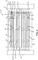
- the filtration media is a layered planar construction very similar to that shown in Fig. 3 , but with several new components.
- the filtration media includes a feed channel 40 (FC) and a high-flux membrane 42 (M1) having a plurality of apertures 55.
- a support structure 44 carries the membrane 42 and the feed channel 40, which may include a spacer material, and, in a manner similar to the previous embodiment, the structure 44 provides for a plurality of holes 48.
- Each support structure 44 provides a handle 75 at each side edge 74 of the support structure which is sized large enough for grasping by a technician.
- Each handle 75 has a groove 76 so as to be slidably movable along the ridge 34 extending inwardly from a wall of the housing.
- Each handle may be supported by a ledge 35.
- the support structure is sized so as to easily carry the membrane and the feed spacer and allow for their removal, if required, from the support structure.
- a permeate spacer 52 Positioned underneath the support structure is a permeate spacer 52 (PS1).
- PS1 permeate spacer 52
- additional layers are provided. These include another high-flux membrane 82 (M2) which has a plurality of apertures 84 which are sized to be smaller than the apertures 55 of the high-flux membrane 42.
- M2 high-flux membrane
- Another support structure 44 is positioned immediately underneath the membrane 82. Positioned underneath this particular support structure is another permeate spacer 86 (PS2).
- PS2 permeate spacer
- the remaining structure of the filtration media is a mirror opposite of the just described variation.
- positioned underneath the second support structure 44 and the permeate spacer 86 is another support structure which has on its underside a membrane 82, another permeate spacer 52, a support structure 44, a membrane 42 and a feed channel 40.
- a leaf structure can be formed by the layered sequence shown or some variation thereof to allow for replacement.
- the layered construction shown in Fig. 4 may be repeated any number of times so as to filter the feedwater material.
- the filtration media is utilized to separate out two components from the feedwater, fluid medium or other material.
- the shown configuration may be utilized to desalinate salt water.
- the feedwater which contains water molecules, monovalent ions and divalent ions is provided to the feed channels 40.
- the feedwater flows through the feed channels, and spacer material if provided, and is projected onto the membranes 42.
- the apertures 55 of the membrane 42 are sized so as to preclude or block the flow of divalent ions.
- the apertures may be sized to about a dimension of about 1.4 nm or in a range of between 1.2 to 1.6 nm. Accordingly, the water molecules and monovalent ions are permitted to flow through these apertures while the divalent ions are blocked. These divalent ions and remaining components that do not flow through the apertures 55 continue through the feed channels and to the outlet of the housing. The water molecules and monovalent ions that flow through the support structure apertures 44 are then received by the permeate spacers 52 and flow toward the membrane 82.
- the membrane 82 provides apertures 84 that are sized to block the monovalent ions and, in the present embodiment, the apertures are believed to have a diameter of about 0.9 nm.
- the apertures may range in size from 0.8 to 1.2 nm. Accordingly, these apertures are adequate to allow for the passage of the water molecules but preclude migration of the monovalent ions. Accordingly, the monovalent ions flow along the permeate spacers 52 along with any water molecules that do not flow through the apertures 84 and are received in the appropriate outlet for further processing. The material not blocked by the membrane 82, the purified water molecules, flows into the permeate spacer 86 and likewise flows to the outlet for further processing.
- the device 10 provides the housing 12 along with a plurality of outputs.
- the housing 12 provides for extension of the feed channel 40 which carries the materials blocked by the membrane 42 and routes the feed channels 40 into an appropriate outlet or conduit for further processing.
- the permeate spacers 52 carry the monovalent ions and presumably a number of water molecules to an appropriate outlet for further processing.
- the permeate spacer 86 carries the water molecules which are free of the salt ions and can be used for the appropriate end-use.
- the embodiment shown in Figs. 4 and 5 is advantageous in that multiple components of a feedwater can be separated and processed. This is useful for when multi-components are included in the feedwater and it will be appreciated that the layering concept utilizing the support structures can facilitate filtering of any number of components from a fluid or gaseous medium. It will also be appreciated that membrane leafs and corresponding components can be replaced as needed if they are damaged or otherwise rendered inoperative. Moreover, the aperture sizes of the membranes can be adjusted as needed for a particular feedwater material. Although the embodiments shown in Figs. 4 and 5 outputs three components, the layered filtration components can be scaled so as to increase the number of constituents provided in a feedwater supply. In other words, by incorporating high-flux membranes that have different aperture sizes, any number of constituents can be removed.
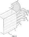
- an alternative filtration device is designated generally by the numeral 100.
- the device 100 provides for a housing 102 and at least one filtration media designated generally by the numeral 106.
- the filtration media is configured in planar circular discs which allow for a more direct collection of the filtered materials.
- the housing 102 provides for a single inlet 110, although multiple inlets could be provided, as long as the same material enters the housing 102.
- the housing 102 also provides an outlet 112 utilized to direct the unfiltered concentrate from the feedwater.
- the concentrate is any material that has not processed through the filters as will be described.
- the housing also includes a permeate conduit 114 and a permeate conduit 116. Both the conduits 114 and 116 are provided to axially extend through the filtration media and out from the housing 102.
- the conduits 114 and 116 are sealed so as to prevent direct entry of the feedwater.
- the conduits 114 and 116 provide the internal support structure for carrying the filtration media.
- the filtration media 106 provides for a circular outer band 120 which serves as a membrane support structure and precludes the flow of material through the bands so as to not enter the areas between the membranes as will be discussed.
- the membranes in this embodiment have the same properties and characteristics as disclosed in the previous embodiments. And, as in the previous embodiments, the media 106 may be utilized to separate and/or filter any multi-component feedwater. Captured by the inner surfaces of the outer band 120 are a pair of opposed and spaced apart end membranes 122. The outer diameter of each end membrane 122 is captured and sealed by the outer band 120.
- Each membrane 122 provides for a plurality of apertures which are sized to block the selected ions. As discussed in the previous embodiment for desalination, the membranes will as one example be utilized to block divalent ions that will flow through the housing 102 with all other rejected material and then exit out the outlet 112.
- a central hub 126 is provided by each end membrane 122 so as to preclude direct entry of feedwater into the conduits 114 and 116.
- One of the hubs 126 will have openings therethrough to receive and carry the conduits 114 and 116.
- Disposed between the two end membranes are a pair of spaced apart inner membranes 130.
- Each inner membrane has an outer diameter that is securely received by the band 120.
- the inner membranes 130 have a plurality of apertures 132 which are configured so as to block the monovalent ions and allow for the water molecules to pass therethrough in the same manner as in the previous embodiment.
- the inner membranes are also provided with inner hubs 134 that receive and carry the conduits 114 and 116 so as to allow for passage of the selected ions and preclude passage of the non-selected ions and other debris.
- a permeate spacer 140 may be disposed between a respective end membrane and an inner membrane.
- a permeate spacer 142 may be disposed between the inner membranes 130.
- the permeate conduit 116 provides conduit openings 144 disposed between the end and inner membranes.
- the permeate conduit 114 provides conduit openings 146 between the inner membranes.
- the feedwater material is projected into the housing and comes in contact with the end membranes 122. Those materials sized to pass through the apertures 124 do so accordingly, while the material that is too large to fit through the apertures continues on through the housing and exits out the outlet 112. Once the material passes through the end membranes it encounters the inner membranes 130. If the material is too large, it will be received and pass through the conduit openings 144 and flow through the conduit 116. If the material is small enough to fit through the apertures 132 of the inner membranes 130, then the filtered material is received and passes into the conduit openings 146 and flows through the conduit 114.
- This embodiment is advantageous in that it allows for the conduits to be centrally located and thus facilitate attachment to various collection vessels. This embodiment also allows for the media 106 to be removed from the housing 102 and for the membranes 122, 130 to be cleaned and/or replaced as needed.
Abstract
A fluid filtration device according to a first aspect of the invention comprises at least one planar filtration media (80). The filtration media (80) comprises at least three planar channels, the at least three planar channels comprising at least one first permeate spacer (52), at least one second permeate spacer (86), and at least one feed channel (40); and at least one first perforated membrane (42) having apertures (55) sized to block a first component of feedwater and at least one second perforated membrane (82) having apertures (84) sized to block a second component of the feedwater; and a membrane support structure (44) associated with each said planar membrane (42, 82). Said at least one first perforated membrane (42) and said at least one second perforated membrane (82) are constructed from a perforated two-dimensional material.
Description
- This application claims priority of United States Provisional Application Serial No.
61/617,261 filed March 29, 2012 - Generally, the present invention relates to filtration and selective fluidic isolation and recovery devices. Specifically, the present invention relates to a layered planar filtration device. More particularly, the present invention is directed to a stacked layer of materials that include at least one high-flux membrane material.
- Currently, nearly half of the online capacity of desalinated water is achieved through a reverse osmosis filtering process. Reverse osmosis market share is growing but current reverse osmosis technology remains capital and energy intensive, with limitations in product design and performance based upon current polymer filtration membranes. The current industry standard for polymer filtration is an eight inch diameter by forty inch length spiral wound membrane with 400 to 440 square feet of active membrane area. Such devices are limited in permeability which in turn limits output water per unit area, or flux, and requires increased membrane area and operating pressures. These high membrane area requirements and operating pressures are a result of membrane resistance (that is, permeability) as well as concentration polarization, scaling, fouling, and the like. Higher flux rates can exacerbate fouling of the filtration membranes. As such, these filtration devices require frequent cleaning and ultimately replacement. The limitations in relation to the flux and associated membrane area requirements result in significant capital cost. The need for high operating pressure devices increase the energy required to operate the filtration device and which further results in degradation of the membrane due to fouling and compaction which also adds to the operating cost.
- Current filtration devices for reverse osmosis utilize an eight inch diameter by forty inch length spiral wound design. Within the filtration media there are twenty to thirty-four membrane leafs which provide for an active membrane area for maximum filtration output water. Although improvements have been made in the filtration media, these are only incremental improvements and do not address the issues raised in regard to limited flux throughput or the requirement for high operating pressures.
- The reverse osmosis approach to filtering and/or desalination is to employ active filtering layers utilizing polyimide components. These components may include composite materials or chemical treatments to modify the properties of the polymer. In all cases such technology utilizes solution diffusion so as to separate the feed material into a concentrate and permeate. In the reverse osmosis technology, the membranes are susceptible to fouling, scaling and compaction. These materials also have limited chemical and biological resistance with limited methods of cleaning, which in turn relates to the need for frequent replacement of the filtration devices.
- Therefore, there is a need in the art for filtration devices that provide for improved flow characteristics, reduced size and weight and increased operational life.. There is also a need for filtration devices to be able to be serviced by replacement of select components instead of replacing whole systems.
- In light of the foregoing, it is an aspect of the present invention to provide a fluid filtration device according to claims 1 and 6.
- It is another aspect of the present invention to provide a filtration or selective fluidic isolation and recovery device comprises a housing having an inlet and an outlet, the housing having an opening extending from the inlet to the outlet an internal support structure maintained in the opening and at least one planar filtration media carried by the internal support structure, the media separating feedwater received at the inlet into at least a permeate and a concentrate that separately exit at the outlet.
- It is yet another aspect of the present invention for the above embodiment to provide at least one filtration media that comprises at least two planar channels, and at least one planar membrane disposed between the at least two planar channels, the planar membrane filtering the feedwater into the permeate and the concentrate.
- It is a further aspect of the present invention for the above embodiment to provide at least one filtration media that further comprises a membrane support structure associated with each planar membrane and carried by the internal support structure, the membrane support structure being removable from the housing for cleaning, servicing or replacement.
- It is still a further aspect of the present invention wherein for the above embodiment one of the at least two planar channels is a permeate spacer disposed between adjacent membrane support structures and the other of the at least two planar channels is a feed channel which has the planar membrane adjacent at least one side thereof.
- A still further aspect of the present invention for the above embodiment provides for a planar membrane that is constructed from perforated graphene material.
- Still another aspect of the present invention in another embodiment provides for each planar membrane disposed between an adjacent membrane structure on one side and an adjacent feed channel.
- Yet another aspect of the present invention in still another embodiment provides for one of the at least three planar channels to be at least one first permeate spacer, at least one second permeate spacer, and at least one feed channel, and wherein the at least one planar membrane is at least one first perforated graphene material having apertures sized to block a first component of the feedwater, and at least one second perforated graphene membrane sized to block a second component of the feedwater.
- A further aspect of the present invention for the above embodiment provides for the first perforated graphene membrane to be positioned between the feed channel and a first of the membrane support structures, wherein the second perforated graphene membrane to be positioned between the at least one first permeate spacer and a second of the membrane support structures, and wherein a first of the at least one second permeate spacer is positioned adjacent a side of the second of the membrane support structures opposite the second perforated graphene membrane.
- Still a further aspect of the present invention comprises for the above embodiment an outlet cap associated with the outlet, the outlet cap having a first permeate pipe associated with the at least one first permeate spacer to collect the second component of feedwater, a second permeate pipe associated with the at least one second permeate spacer to collect components of feedwater not blocked by the first and second membranes, and a concentrate pipe associated with the feed spacer to collect the first component of feedwater.
- A further aspect of the present invention in yet another embodiment comprises a switchable voltage supply, wherein the planar membrane is perforated graphene electrically conductive and connected to the switchable voltage supply to electrically charge the planar membrane to disrupt effects of concentration polarization for polarized species included in the feedwater.
- An additional aspect of the present invention in a further embodiment comprises a switchable voltage supply, wherein the planar membrane receives a direct current electrical charge from the switchable voltage supply for a specified duration and is then removed for the purposes of destroying or disabling biological contaminants upon the planar membrane and/or surrounding structures.
- A still further aspect of the present invention in another embodiment provides for the filtration media comprising a pair of spaced apart inner membranes, each inner membrane having an outer diameter coupled to the membrane support structure, and a permeate spacer disposed between the inner membranes, and wherein the internal support structure comprises at least one outlet conduit, wherein the at least one outlet conduit has openings adjacent the permeate spacer.
- Yet a further aspect of the present invention for the above embodiment provides for the filtration media further comprising a pair of spaced apart end membranes, each end membrane having an outer diameter coupled to the membrane support structure, and another permeate spacer disposed between each adjacent end membrane and the inner membrane, and wherein the internal support structure further comprises another outlet conduit, wherein the another outlet conduit has openings adjacent the another permeate spacer.
- And still another aspect of the present invention in a different embodiment includes the planar layered filtration media being configured for selective isolation and recovery of desired particulates, solutes, or analytes, as opposed to filtering out unwanted particulates, solutes, or analytes for two or more concentrate streams.
- This and other features and advantages of the present invention will become better understood with regard to the following description, appended claims, and accompanying drawings wherein:
-
Fig. 1 is a right side enlarged perspective schematic view of a planar filtration device carried in a housing according to the concepts of the present invention; -
Fig. 2 is a left side enlarged perspective schematic view of the planar filtration device carried in the housing according to the concepts of the present invention; -
Fig. 3 is a cross-sectional and enlarged schematic view of the filtration device according to the concepts of the present invention; -
Fig. 4 is a cross-sectional and enlarged schematic view of an alternative filtration device according to the concepts of the present invention; -
Fig 5 is a schematic view of an outlet cap to separate two or more output streams from the filtration device with a planar membrane arrangement; and -
Fig. 6 is a cross-sectional and enlarged schematic view of another alternative filtration device according to the concepts of the present invention. - Referring now to
Figs. 1 and 2 , it can be seen that a filtration device is designated generally by thenumeral 10.Fig. 1 presents a general perspective cross-sectional view of an inlet side whileFig. 2 presents a perspective general cross-sectional view of an outlet side of the filtration device. Thedevice 10 includes ahousing 12 which may be of a cylindrical construction as shown, but other shapes are believed to be possible depending upon end-use applications. In any event, thehousing 12 includes aninlet 14 which receivesfeedwater 15 or other fluid for filtration or selective fluidic isolation and recovery. Although the term feedwater is used throughout this description, it will be appreciated that the feedwater or fluid material provided to the filtration device may not include water. As used herein, feedwater refers to the medium that includes components supplied to the filtration device for separation and removal. In another embodiment, the feedwater may contain particulates, solutes, or analytes of interest for selective fluidic isolation and recovery. Attached to theinlet 14 is aninlet cap 16 which includes afeedwater pipe 18 that allows the feedwater to be directed into the housing. As will be appreciated by skilled artisans, theinlet cap 16 directs the receivedfeedwater 15 into a plurality of feed spacers as will be described. In some embodiments, thecap 16 may have conduits to direct the feedwater into the feed channels. In other embodiments, the feed channels may be surrounded by a nonporous surface such that the feedwater is directed into the feed channels. - An
outlet 22 is disposed at an opposite end of thehousing 12 and provides anoutlet cap 24. Theoutlet cap 24 includes apermeate pipe 26 and aconcentrate pipe 27. These pipes or conduits direct the filtered feedwater -- apermeate 28 and aconcentrate 29, sometimes called a residue -- based upon their properties after filtration, for further use. Theoutlet cap 24 is configured to maintain the separation of the permeate from the concentrate. - Referring now to
Figs. 1-3 , it can be seen that thehousing 12 includes anopening 32 which extends the entire length thereof. Maintained within thehousing 12 is an internal support structure which includes a series ofridges 34 andledges 35, steps or other structural features so as to support a filtration media designated generally by the numeral 36. As seen, theinternal support structure housing 12. - The
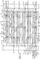
filtration media 36 includes a planar layered configuration which includes at least onefeed channel 40, at least one high-flux membrane 42, at least one membraneporous support structure 44, which is sometimes referred to as a porous backing, and at least onepermeate spacer 52. The letter designations FC (feed channel 40), M (membrane 42), SS (support structure 44) and PS (permeate spacer 52) are provided to provide a clear designation as to each layer. It will be appreciated that although the various layers of filtration media are shown slightly spaced apart for clarity purposes, in practice the various adjacent layers are likely in touching contact with one another, with seals as appropriate between membranes, flow channels, and permeate spacers so as to provide separated flow paths between permeate and concentrate. Different positional arrangements of the aforementioned components can be utilized depending upon the components in the feedwater and how the components can best be efficiently separated or filtered from one another. As used herein, the feedwater may contain undesired constituents such as sodium, chlorine, salts, toxins, virus, bacteria, and other suspended contaminants of similar size that is carried by a fluid medium such as a solvent or water. - Generally, the feedwater is received by at least one
feed channel 40 which delivers the feedwater to a high-flux membrane 42 that is supported by thesupport structure 44. Thefeed channel 40 may contain either a woven or non-woven spacer material. The feed spacer material is constructed from a polymeric material such as polypropylene, polyethylene, polyester, polyamides, and/or fluoropolymers. Non-polymeric materials such as porous ceramics or porous sintered metals, or other materials possessing desirable hydrodynamic and application specific properties may also be used for the feed spacer material. The feed channel's physical configuration features a geometry optimized to support membrane performance and as such may have a thickness of between 0.02" to 0.04". Other embodiments may use thicknesses of between 0.02" to 0.20" for the feed channel and corresponding spacer, if used. Thefeed channel 40 is configured to allow the feedwater to flow from the inlet toward the outlet. Eachmembrane support structure 44 includes a plurality ofholes 48 such that the porous support structure provides minimal flow resistance. In the present embodiment, the support structure is constructed from a polymeric material such as polycarbonate or polyester, which may be used in conjunction to comprise a laminated or composite backing structure depending on the application. Other materials with similar hydrodynamic and structural properties could be used, including carbon nano-structured materials, ceramics, and sintered porous metals. Theholes 48 are sized anywhere between 15 nanometers to 200 nanometers in diameter and may be spaced apart from one another depending on hole size used. It is desirable to use backing material as open as possible to maintain a desirable flow while adequately supporting the membrane. Indeed, astructure 44 having an open area of up to 25% could be used. Other hole sizing and spacing may be used. The spacer, if used infeed channel 40, can be used to set a channel height for the feedwater to flow into and through. In some embodiments the channel height may be sized to accommodate a range of channel spacer designs to receive amechanical mechanism 54 that generates turbulence of the feedwater prior to its entering themembrane 42. The mechanical mechanisms may include, but are not limited to, ribs or protrusions that are adjacent or integral with thefeed channel 40. Turbulence may also be generated by use of a feed spacer in the form of a mesh that is constructed with ribs and spacers. An exemplary material is sold under the trade name Naltex ™ by DelStar Technologies, Inc. of Middletown, DE, USA. Turbulence may also be generated by electrical mechanisms which may include, but are not limited to alternating current or direct current charge. - In the present embodiment, the high-
flux membrane 42 is a graphene membrane as described inU.S. Patent No. 8,361,321 , which is incorporated herein by reference. The graphene membrane is a single-atomic-layer-thick layer of carbon atoms, bound together to define a sheet. The thickness of a single graphene membrane, which may be referred to as a layer or a sheet, is approximately 0.2 to 0.3 nanometers (nm). In some embodiments, multiple graphene layers can be formed, having greater thickness and correspondingly greater strength. Multiple graphene sheets can be provided in multiple layers as the membrane is grown or formed, and is commonly known as few layer graphene. Or multiple graphene sheets can be achieved by layering or positioning one graphene layer on top of another. For all the embodiments disclosed herein, a single layer of graphene or multiple graphene layers may be used. Testing reveals that multiple layers of graphene maintain their integrity and function, possibly as a result of self-adhesion. This improves the strength of the membrane and in some cases flow performance. The perforated graphene high-flux throughput material provides significantly improved filtration properties, as opposed to polyamide or other polymeric material filtration materials. In most embodiments, the graphene membrane is 0.5 to 2 nanometers thick. The carbon atoms of the graphene layer define a repeating pattern of hexagonal ring structures (benzene rings) constructed of six carbon atoms, which form a honeycomb lattice of carbon atoms. An interstitial aperture is formed by each six carbon atom ring structure in the sheet and this interstitial aperture is less than one nanometer across. Indeed, skilled artisans will appreciate that the interstitial aperture is believed to be about 0.23 nanometers across at its longest dimension. Accordingly, the dimension and configuration of the interstitial aperture and the electron nature of the graphene precludes transport of any molecule across the graphene's thickness unless there are perforations. This dimension is much too small to allow the passage of either water or ions. - In order to form the perforated graphene membrane, one or more perforations are made. A representative generally or nominally round aperture or
perforation 55 is defined through thegraphene membrane 42.Aperture 55 has a nominal diameter of about 0.6 nanometers. The six tenth nanometer dimension is selected to block the smallest of the ions which would ordinarily be expected in salt or brackish water, which is the sodium ion. The generally round shape of theaperture 55 is affected by the fact that the edges of the aperture are defined, in part, by the hexagonal carbon ring structure of thegraphene membrane 42. Other aperture sizes may be selected depending upon the constituents of the feedwater and the constituents or components of the feedwater that is desired to be blocked or filtered. Accordingly, theapertures 55 may range in size from 0.5 nm to 1.2 nm in some embodiments, or from 1.0 to 10 nm in other embodiments. And in other embodiments, the size of the apertures may range from 10 nm to 100 nm. - Apertures in the graphene membrane may be made by selective oxidation, by which is meant exposure to an oxidizing agent for a selected period of time. It is believed that the
aperture 55 can also be laser-drilled. As described in the publication Nano Lett. 2008, Vol.8, no.7, pg 1965-1970, the most straightforward perforation strategy is to treat the graphene film with dilute oxygen in argon at elevated temperature. As described therein, through apertures or holes in the 20 to 180 nm range were etched in graphene using 350 mTorr of oxygen in 1 atmosphere (atm) argon at 500°C for 2 hours. The paper reasonably suggests that the number of holes is related to defects in the graphene sheet and the size of the holes is related to the residence time. This is believed to be the preferred method for making the desired perforations in graphene structures. The structures may be graphene nanoplatelets and graphene nanoribbons. Thus, apertures in the desired range can be formed by shorter oxidation times. Another more involved method as described in Kim et al. "Fabrication and Characterization of Large Area, Semiconducting Nanoperforated Graphene Material, " Nano Letters 2010 Vol. 10, No. 4, March 1, 2010, pp 1125-1131 utilizes a self assembling polymer that creates a mask suitable for patterning using reactive ion etching. A P(S-blockMMA) block copolymer forms an array of PMMA columns that form vias for the RIE upon redeveloping. The pattern of holes is very dense. The number and size of holes is controlled by the molecular weight of the PMMA block and the weight fraction of the PMMA in the P(S-MMA). Either method has the potential to produce perforated graphene sheets. Other methods of forming the apertures may be employed. - In the embodiments disclosed herein, it will be appreciated that the apertures are sized to block selected components of the feedwater and allow passage of other components. Moreover, the edges of the apertures may be modified to assist in blocking or passing of selected components. Although graphene is an exemplary two dimensional material for use as the high-
flux membrane 42, skilled artisans will appreciate that other materials such as boron nitride, metal chalcogenides, silicene and germanene, and molybdenum disulfide could offer two dimensional thinness, although use of these materials for filtration applications is not known to be as ideal as graphene. In any event, themembrane 42 functions to preclude passage of unwanted components of the feedwater while allowing the desired components to pass therethrough and, accordingly through the structure holes 48. As such, by reduced operating pressure, the material not blocked by the membrane flows through themembrane apertures 55 and themembrane support structure 44 and is delivered to thepermeate spacer 52. As an end result, the material blocked by the membrane continues through thefeed channel 40 while the unblocked material proceeds and flows through thepermeate spacer 52. In the present embodiment, thepermeate spacer 52 is constructed and sized for compressive loads which will have a substantially different magnitude from those of thefeed channel 40 for high pressure operation. The purpose of the permeate spacers differs as it primarily provides structural support to the membrane and does not generally serve to produce flow turbulence as does the feed spacer material if disposed in thefeed channel 40. The permeate spacer also provides a conduit for permeate flow from the back side of the membrane to a common permeate collection means. Skilled artisans will appreciate that construction and sizing of the permeate spacer may be varied depending upon the characteristics of the feedwater and therefore the operating pressure and permeate flux rate. - The
channels 40 andspacers 52 directly feed their respective fluids into the permeate pipe 26 (the permeate spacer 52) and the concentrate pipe 30 (the feed spacer 42). - In some embodiments, the aforementioned electrical mechanism for generating turbulence is a switched
voltage supply 70, which is maintained outside the housing but could be within the housing, is connected to themembrane 42 by a pair ofconductors 72. In most embodiments, the conductors are attached at diametrically opposite ends of themembrane 42. As skilled artisans will appreciate, application of an electrical voltage to themembrane 42 that is graphene or has some other electrically conductive material generates a repulsive force that causes turbulence that is transmitted or transferred to the feedwater, in particular the polarized salt ions within the feedwater. In some embodiments, the forces will be alternated between repulsive and attractive to produce maximum turbulence. This turbulence assists in moving the permeate through the various layers. In the perforated graphene embodiment, the material is able to conduct an electrical charge which can be controlled to disrupt concentration polarization, thereby lowering operating pressure. Moreover, it is believed that an electrically charged graphene membrane is an ideal conductive material that will support the necessary charge to disrupt biological accumulation on the membrane surface or surrounding supporting structures. By applying a direct current or alternating current electrical charge from thesupply 70 for a specified duration and then removing the charge, biological contaminants on the membrane and/or surrounding structures can be destroyed or disabled. - As skilled artisans will appreciate, the
channels 40, thespacers 52, thesupport structure 44, and themembrane 42 are of a planar construction. In other words, each are provided with a width and length which receives the feed supply and the filtered fluid. - In the present embodiment the
support structure 44, along with themembranes 42 which they support, are removable from the housing by virtue of their retention by theinternal support structure 34. Thesupport structure 44 includes alateral edge 74 along each side that provides ahandle 75. Each handle 75 includes agroove 76. Eachgroove 76 is slidably receivable on acorresponding ridge 34. Additionally, an underside of each handle 75 may be slidably received on and supported by a correspondingledge 35. Thesupport structure 44 can be mechanically fastened to the internal support structure --ridges 34,ledges 35 -- to maintain pressure during operation. Unfastening of the support structures allows access to the membranes located inside the housing. - In the embodiment shown in
Fig. 3 , theuppermost support structure 44 supports amembrane 42. The feedwater flows through themembrane 42 via theapertures 55 and themembrane support 44 via theholes 48 and is received by thepermeate spacer 52. Disposed on the underside of thatparticular permeate spacer 52 is anothersupport structure 44 which has on its other side anothermembrane 42. Anotherfeed channel 40 is disposed adjacent that membrane. As such, any feedwater that enters one of theinner feed channels 40 may enter amembrane 42 immediately above or immediately below wherein the material that flows therethrough enters theappropriate permeate spacer 52. A feed spacer material may be used to keep the membranes separated from each other. Flow through the device moves from input side to output side down the length of the housing, with permeate flow moving down the permeate channel and feedwater flow moving down the feedwater channel, tangential to the membrane surface. This direction is in and out of the page as viewed inFig 3 . The directional arrows provided inFig. 3 (and later inFig. 4 ) are for the purpose of showing how the feedwater flows from one layer to another. As can be seen by viewing thefiltration media 36, eachsupport structure 44 is associated with amembrane 42 on one side thereof and anappropriate permeate spacer 52 on an opposite side. This stacked planar design is conducive for replacing membranes as needed. - The
filtration media 36 is configured to optimize the relationship of the various layers with one another. As such, eachfeed channel 40 has at least one membrane on one side thereof, and in some instances both sides. Eachpermeate spacer 52 has asupport structure 44 on both sides thereof. Finally, each membrane is positioned between asupport structure 44 on one side and a feed spacer on an opposite side. The filtered material that collects in thepermeate spacer 52 then flows out the housing through thepermeate pipe 26. The unfiltered or blocked material that remains in the feed channel flows out the housing through theconcentrate pipe 29. - It will also be appreciated that adjacent layers cold be specifically associated with one another. For example, a layered sequence of a
membrane 42, asupport structure 44, apermeate spacer 52, another support structure and anothermembrane 42 could be configured so as to form a membrane leaf structure. The leaf structure could be a replaceable unit and could be removed and replaced if found defective. The associated support structures could be secured to one another to facilitate insertion and removal. Other repeating sequences could be configured as a leaf structure. - The
filtration device 10 has several readily apparent advantages. By utilizing ultra thin or two-dimensional materials, a layered plate design is able to be obtained instead of a spiral wound design. In the case of an ultra-permeable membrane such as perforated graphene, the layered plate design can be utilized at reduced overall size compared to current state of the art filtration devices while maintaining the benefits of linear scalability, membrane accessibility, and channel design to mitigate the effects of concentration polarization, scaling fouling and the like. Indeed, use of a high flux throughput material, such as perforated graphene or the like, allows for a reduction in membrane surface area by a factor of anywhere between five to fifty times. The present embodiments are also advantageous in that they increase the ease of assembly and reduce manufacturing requirements by use of the removable support structures, spacers and membranes. Still yet another advantage of thefiltration device 10 is that it allows for multiple devices to be attached in series to provide additional filtering as needed. - Referring now to
Figs. 4 and5 , an alternative embodiment of a filtration device having a filtration media designated generally by the numeral 80 is shown. Themedia 80 is receivable in thehousing 12 and receives feedwater input in substantially the same way as shown inFig. 1 . The output of thefiltration media 80 is different and will be described in relation toFig. 5 . In any event, the filtration media is a layered planar construction very similar to that shown inFig. 3 , but with several new components. As in the previous embodiment, the filtration media includes a feed channel 40 (FC) and a high-flux membrane 42 (M1) having a plurality ofapertures 55. - A support structure 44 (SS) carries the
membrane 42 and thefeed channel 40, which may include a spacer material, and, in a manner similar to the previous embodiment, thestructure 44 provides for a plurality ofholes 48. Eachsupport structure 44 provides ahandle 75 at eachside edge 74 of the support structure which is sized large enough for grasping by a technician. Each handle 75 has agroove 76 so as to be slidably movable along theridge 34 extending inwardly from a wall of the housing. Each handle may be supported by aledge 35. The support structure is sized so as to easily carry the membrane and the feed spacer and allow for their removal, if required, from the support structure. Positioned underneath the support structure is a permeate spacer 52 (PS1). The layers in themedia 80 are substantially the same as that disclosed for themedia 36. - For the
filtration media 80, additional layers are provided. These include another high-flux membrane 82 (M2) which has a plurality ofapertures 84 which are sized to be smaller than theapertures 55 of the high-flux membrane 42. Anothersupport structure 44 is positioned immediately underneath themembrane 82. Positioned underneath this particular support structure is another permeate spacer 86 (PS2). The remaining structure of the filtration media is a mirror opposite of the just described variation. In other words, positioned underneath thesecond support structure 44 and thepermeate spacer 86 is another support structure which has on its underside amembrane 82, anotherpermeate spacer 52, asupport structure 44, amembrane 42 and afeed channel 40. In a manner similar to the previous embodiment, a leaf structure can be formed by the layered sequence shown or some variation thereof to allow for replacement. - Skilled artisans will appreciate that the layered construction shown in
Fig. 4 may be repeated any number of times so as to filter the feedwater material. In the embodiment shown the filtration media is utilized to separate out two components from the feedwater, fluid medium or other material. For example purposes only, the shown configuration may be utilized to desalinate salt water. Accordingly, the feedwater which contains water molecules, monovalent ions and divalent ions is provided to thefeed channels 40. The feedwater flows through the feed channels, and spacer material if provided, and is projected onto themembranes 42. Theapertures 55 of themembrane 42 are sized so as to preclude or block the flow of divalent ions. As such, the apertures may be sized to about a dimension of about 1.4 nm or in a range of between 1.2 to 1.6 nm. Accordingly, the water molecules and monovalent ions are permitted to flow through these apertures while the divalent ions are blocked. These divalent ions and remaining components that do not flow through theapertures 55 continue through the feed channels and to the outlet of the housing. The water molecules and monovalent ions that flow through thesupport structure apertures 44 are then received by thepermeate spacers 52 and flow toward themembrane 82. Themembrane 82 providesapertures 84 that are sized to block the monovalent ions and, in the present embodiment, the apertures are believed to have a diameter of about 0.9 nm. In some embodiments, the apertures may range in size from 0.8 to 1.2 nm. Accordingly, these apertures are adequate to allow for the passage of the water molecules but preclude migration of the monovalent ions. Accordingly, the monovalent ions flow along thepermeate spacers 52 along with any water molecules that do not flow through theapertures 84 and are received in the appropriate outlet for further processing. The material not blocked by themembrane 82, the purified water molecules, flows into thepermeate spacer 86 and likewise flows to the outlet for further processing. - As best seen in
Fig. 5 , thedevice 10 provides thehousing 12 along with a plurality of outputs. In particular, thehousing 12 provides for extension of thefeed channel 40 which carries the materials blocked by themembrane 42 and routes thefeed channels 40 into an appropriate outlet or conduit for further processing. In a similar manner, thepermeate spacers 52 carry the monovalent ions and presumably a number of water molecules to an appropriate outlet for further processing. Finally, thepermeate spacer 86 carries the water molecules which are free of the salt ions and can be used for the appropriate end-use. - The embodiment shown in
Figs. 4 and5 is advantageous in that multiple components of a feedwater can be separated and processed. This is useful for when multi-components are included in the feedwater and it will be appreciated that the layering concept utilizing the support structures can facilitate filtering of any number of components from a fluid or gaseous medium. It will also be appreciated that membrane leafs and corresponding components can be replaced as needed if they are damaged or otherwise rendered inoperative. Moreover, the aperture sizes of the membranes can be adjusted as needed for a particular feedwater material. Although the embodiments shown inFigs. 4 and5 outputs three components, the layered filtration components can be scaled so as to increase the number of constituents provided in a feedwater supply. In other words, by incorporating high-flux membranes that have different aperture sizes, any number of constituents can be removed. - Referring now to
Fig. 6 , it can be seen that an alternative filtration device is designated generally by the numeral 100. Thedevice 100 provides for ahousing 102 and at least one filtration media designated generally by the numeral 106. In this particular embodiment, instead of employing a planar rectangular filtration media, it will be appreciated that the filtration media is configured in planar circular discs which allow for a more direct collection of the filtered materials. Thehousing 102 provides for asingle inlet 110, although multiple inlets could be provided, as long as the same material enters thehousing 102. Thehousing 102 also provides anoutlet 112 utilized to direct the unfiltered concentrate from the feedwater. As noted previously, the concentrate is any material that has not processed through the filters as will be described. The housing also includes apermeate conduit 114 and apermeate conduit 116. Both theconduits housing 102. Theconduits conduits - The
filtration media 106 provides for a circularouter band 120 which serves as a membrane support structure and precludes the flow of material through the bands so as to not enter the areas between the membranes as will be discussed. The membranes in this embodiment have the same properties and characteristics as disclosed in the previous embodiments. And, as in the previous embodiments, themedia 106 may be utilized to separate and/or filter any multi-component feedwater. Captured by the inner surfaces of theouter band 120 are a pair of opposed and spaced apart endmembranes 122. The outer diameter of eachend membrane 122 is captured and sealed by theouter band 120. Eachmembrane 122 provides for a plurality of apertures which are sized to block the selected ions. As discussed in the previous embodiment for desalination, the membranes will as one example be utilized to block divalent ions that will flow through thehousing 102 with all other rejected material and then exit out theoutlet 112. - A
central hub 126 is provided by eachend membrane 122 so as to preclude direct entry of feedwater into theconduits hubs 126 will have openings therethrough to receive and carry theconduits inner membranes 130. Each inner membrane has an outer diameter that is securely received by theband 120. Theinner membranes 130 have a plurality ofapertures 132 which are configured so as to block the monovalent ions and allow for the water molecules to pass therethrough in the same manner as in the previous embodiment. The inner membranes are also provided withinner hubs 134 that receive and carry theconduits permeate spacer 140 may be disposed between a respective end membrane and an inner membrane. In a similar manner, apermeate spacer 142 may be disposed between theinner membranes 130. Thepermeate conduit 116 providesconduit openings 144 disposed between the end and inner membranes. In a similar manner, thepermeate conduit 114 providesconduit openings 146 between the inner membranes. - Accordingly, in operation the feedwater material is projected into the housing and comes in contact with the
end membranes 122. Those materials sized to pass through theapertures 124 do so accordingly, while the material that is too large to fit through the apertures continues on through the housing and exits out theoutlet 112. Once the material passes through the end membranes it encounters theinner membranes 130. If the material is too large, it will be received and pass through theconduit openings 144 and flow through theconduit 116. If the material is small enough to fit through theapertures 132 of theinner membranes 130, then the filtered material is received and passes into theconduit openings 146 and flows through theconduit 114. - This embodiment is advantageous in that it allows for the conduits to be centrally located and thus facilitate attachment to various collection vessels. This embodiment also allows for the
media 106 to be removed from thehousing 102 and for themembranes - Thus, it can be seen that the objects of the invention have been satisfied by the structure and its method for use presented above. While in accordance with the Patent Statutes, only the best mode and preferred embodiment has been presented and described in detail, it is to be understood that the invention is not limited thereto or thereby. Accordingly, for an appreciation of the true scope and breadth of the invention, reference should be made to the following claims.
Claims (7)
- A fluid filtration device, comprising:at least one planar filtration media (80), wherein the filtration media (80) comprisesat least three planar channels, the at least three planar channels comprising at least one first permeate spacer (52), at least one second permeate spacer (86), and at least one feed channel (40); andat least one first perforated membrane (42) having apertures (55) sized to block a first component of feedwater and at least one second perforated membrane (82) having apertures (84) sized to block a second component of the feedwater, the apertures (55) of the at least one first perforated membrane (42) being greater in size than the apertures (84) of the at least one second perforated membrane (82); anda membrane support structure (44) associated with each said planar membrane (42, 82); andwherein said at least one first perforated membrane (42) and said at least one second perforated membrane (82) are constructed from a perforated two-dimensional material.
- The device according to claim 1, wherein the at least one first perforated membrane (42) is a first perforated graphene membrane and the at least one second perforated membrane (82) is a second perforated graphene membrane.
- The device according to claim 1 or 2, wherein the aperture size of the at least one first perforated membrane (42) is greater than the aperture size of the at least one second perforated membrane (82).
- The device according to claim 3, wherein said at least one first perforated membrane (42) has apertures sized between 1.2 nm to 1.6 nm and said at least one second perforated membrane (82) has apertures sized from 0.8 nm to 1.2 nm.
- The device according to claim 1 or 2, wherein the at least one planar filtration media further comprises an additional first perforated membrane, an additional second perforated membrane, an additional feed channel, and an additional first permeate spacer.
- A fluid filtration device, comprising:at least one planar filtration media (106), wherein the filtration media (106) comprises:a pair of spaced apart end membranes (122), each of said end membranes (122) comprising a first planar membrane, an outer diameter, and an aperture size;a pair of spaced apart inner membranes (130), each of said inner membranes (130) comprising a second planar membrane, an outer diameter, and an aperture size;a first permeate spacer (142) disposed between said pair of inner membranes (130) and a second permeate spacer (140) disposed between each of said pair of inner membranes (130) and each adjacent end membrane (122), andwherein the aperture size of said end membranes (122) is greater than the aperture size of said inner membranes (130), andwherein said end membranes (122) and said inner membranes (130) are constructed from a perforated graphene material.
- The device of claim 6, wherein the apertures of the end membranes (122) are from 1.2 to 1.6 mm and the apertures of the inner membranes (130) are from 0.8 nm to 1.2 nm.
Applications Claiming Priority (2)
| Application Number | Priority Date | Filing Date | Title |
|---|---|---|---|
| US201261617261P | 2012-03-29 | 2012-03-29 | |
| EP13715529.7A EP2830746B1 (en) | 2012-03-29 | 2013-03-22 | Planar filtration and selective isolation and recovery device |
Related Parent Applications (2)
| Application Number | Title | Priority Date | Filing Date |
|---|---|---|---|
| EP13715529.7A Division-Into EP2830746B1 (en) | 2012-03-29 | 2013-03-22 | Planar filtration and selective isolation and recovery device |
| EP13715529.7A Division EP2830746B1 (en) | 2012-03-29 | 2013-03-22 | Planar filtration and selective isolation and recovery device |
Publications (1)
| Publication Number | Publication Date |
|---|---|
| EP3213810A1 true EP3213810A1 (en) | 2017-09-06 |
Family
ID=48083638
Family Applications (2)
| Application Number | Title | Priority Date | Filing Date |
|---|---|---|---|
| EP13715529.7A Not-in-force EP2830746B1 (en) | 2012-03-29 | 2013-03-22 | Planar filtration and selective isolation and recovery device |
| EP17164883.5A Withdrawn EP3213810A1 (en) | 2012-03-29 | 2013-03-22 | Planar filtration device comprising 2-dimensional membranes |
Family Applications Before (1)
| Application Number | Title | Priority Date | Filing Date |
|---|---|---|---|
| EP13715529.7A Not-in-force EP2830746B1 (en) | 2012-03-29 | 2013-03-22 | Planar filtration and selective isolation and recovery device |
Country Status (13)
| Country | Link |
|---|---|
| US (2) | US9463421B2 (en) |
| EP (2) | EP2830746B1 (en) |
| JP (1) | JP6270815B2 (en) |
| KR (1) | KR20150001786A (en) |
| CN (1) | CN104245098B (en) |
| AU (1) | AU2013240071A1 (en) |
| CA (1) | CA2866866A1 (en) |
| ES (1) | ES2639162T3 (en) |
| IL (1) | IL234827A0 (en) |
| IN (1) | IN2014DN07848A (en) |
| SA (1) | SA113340424B1 (en) |
| SG (1) | SG11201405624TA (en) |
| WO (1) | WO2013148479A1 (en) |
Families Citing this family (31)
| Publication number | Priority date | Publication date | Assignee | Title |
|---|---|---|---|---|
| US9475709B2 (en) | 2010-08-25 | 2016-10-25 | Lockheed Martin Corporation | Perforated graphene deionization or desalination |
| US9193587B2 (en) | 2011-07-13 | 2015-11-24 | Lockheed Martin Corporation | System and method for water purification and desalination |
| WO2013142133A1 (en) | 2012-03-21 | 2013-09-26 | Lockheed Martin Corporation | Methods for perforating graphene using an activated gas stream and perforated graphene produced therefrom |
| US9463421B2 (en) * | 2012-03-29 | 2016-10-11 | Lockheed Martin Corporation | Planar filtration and selective isolation and recovery device |
| US9095823B2 (en) | 2012-03-29 | 2015-08-04 | Lockheed Martin Corporation | Tunable layered membrane configuration for filtration and selective isolation and recovery devices |
| US9744617B2 (en) | 2014-01-31 | 2017-08-29 | Lockheed Martin Corporation | Methods for perforating multi-layer graphene through ion bombardment |
| US9834809B2 (en) | 2014-02-28 | 2017-12-05 | Lockheed Martin Corporation | Syringe for obtaining nano-sized materials for selective assays and related methods of use |
| US10653824B2 (en) | 2012-05-25 | 2020-05-19 | Lockheed Martin Corporation | Two-dimensional materials and uses thereof |
| US10418143B2 (en) | 2015-08-05 | 2019-09-17 | Lockheed Martin Corporation | Perforatable sheets of graphene-based material |
| US9067811B1 (en) * | 2012-05-25 | 2015-06-30 | Lockheed Martin Corporation | System, method, and control for graphenoid desalination |
| US9610546B2 (en) | 2014-03-12 | 2017-04-04 | Lockheed Martin Corporation | Separation membranes formed from perforated graphene and methods for use thereof |
| WO2014164621A1 (en) | 2013-03-12 | 2014-10-09 | Lockheed Martin Corporation | Method for forming filter with uniform aperture size |
| US9505192B2 (en) | 2013-03-13 | 2016-11-29 | Lockheed Martin Corporation | Nanoporous membranes and methods for making the same |
| US9480952B2 (en) | 2013-03-14 | 2016-11-01 | Lockheed Martin Corporation | Methods for chemical reaction perforation of atomically thin materials |
| US9572918B2 (en) | 2013-06-21 | 2017-02-21 | Lockheed Martin Corporation | Graphene-based filter for isolating a substance from blood |
| AU2015210875A1 (en) | 2014-01-31 | 2016-09-15 | Lockheed Martin Corporation | Processes for forming composite structures with a two-dimensional material using a porous, non-sacrificial supporting layer |
| KR20160142820A (en) | 2014-01-31 | 2016-12-13 | 록히드 마틴 코포레이션 | Perforating two-dimensional materials using broad ion field |
| AU2015229331A1 (en) | 2014-03-12 | 2016-10-27 | Lockheed Martin Corporation | Separation membranes formed from perforated graphene |
| EP3140028A4 (en) * | 2014-05-08 | 2018-01-03 | Lockheed Martin Corporation | Stacked two-dimensional materials and methods for producing structures incorporating same |
| CN106457162A (en) * | 2014-06-30 | 2017-02-22 | 国立大学法人信州大学 | Method for perforating carbon nanomaterial, and method for producing filter molded article |
| WO2016036888A1 (en) | 2014-09-02 | 2016-03-10 | Lockheed Martin Corporation | Hemodialysis and hemofiltration membranes based upon a two-dimensional membrane material and methods employing same |
| US10464025B2 (en) | 2014-12-04 | 2019-11-05 | Shinshu University | Method for producing molded filter body |
| EP3259382B1 (en) | 2015-02-20 | 2021-06-30 | Northeastern University | Device comprising an ultrathin membrane composed of an atomically-thin 2d material |
| CA2994664A1 (en) | 2015-08-06 | 2017-02-09 | Lockheed Martin Corporation | Nanoparticle modification and perforation of graphene |
| WO2017180137A1 (en) | 2016-04-14 | 2017-10-19 | Lockheed Martin Corporation | Method for treating graphene sheets for large-scale transfer using free-float method |
| WO2017180134A1 (en) | 2016-04-14 | 2017-10-19 | Lockheed Martin Corporation | Methods for in vivo and in vitro use of graphene and other two-dimensional materials |
| WO2017180135A1 (en) | 2016-04-14 | 2017-10-19 | Lockheed Martin Corporation | Membranes with tunable selectivity |
| CA3020880A1 (en) | 2016-04-14 | 2017-10-19 | Lockheed Martin Corporation | Selective interfacial mitigation of graphene defects |
| EP3443329A4 (en) | 2016-04-14 | 2020-04-08 | Lockheed Martin Corporation | Methods for in situ monitoring and control of defect formation or healing |
| SG11201809015WA (en) | 2016-04-14 | 2018-11-29 | Lockheed Corp | Two-dimensional membrane structures having flow passages |
| CN111229044B (en) * | 2018-11-29 | 2021-07-27 | 中国科学院大连化学物理研究所 | Dish tubular separation membrane subassembly |
Citations (5)
| Publication number | Priority date | Publication date | Assignee | Title |
|---|---|---|---|---|
| EP1777250A1 (en) * | 2005-10-15 | 2007-04-25 | DECHEMA Gesellschaft für Chemische Technologie und Biotechnologie e.V. | Process for preventing or reducing biofilms on a substrate |
| WO2009129984A1 (en) * | 2008-04-21 | 2009-10-29 | Ntnu Technology Transfer As | Carbon membranes from cellulose esters |
| WO2011063458A1 (en) * | 2009-11-25 | 2011-06-03 | University Of Sydney | Membrane and membrane separation system |
| US20120048804A1 (en) * | 2010-08-25 | 2012-03-01 | Lockheed Martin Corporation | Perforated graphene deionization or desalination |
| KR20120022164A (en) * | 2010-09-01 | 2012-03-12 | 연세대학교 산학협력단 | Net of graphene nano filter, graphene nano filter and manufacturing method |
Family Cites Families (53)
| Publication number | Priority date | Publication date | Assignee | Title |
|---|---|---|---|---|
| US4277344A (en) | 1979-02-22 | 1981-07-07 | Filmtec Corporation | Interfacially synthesized reverse osmosis membrane |
| JPS59102111U (en) * | 1982-12-27 | 1984-07-10 | 日東電工株式会社 | Laminated cartridge filter |
| US4855058A (en) | 1986-06-24 | 1989-08-08 | Hydranautics | High recovery spiral wound membrane element |
| US4880440A (en) * | 1988-09-12 | 1989-11-14 | Union Carbide Corporation | Hollow fiber multimembrane cells and permeators |
| US4889626A (en) | 1988-11-17 | 1989-12-26 | Memron, Inc. | Filter cartridge having a tunable asymmetric fluoropolymer alloy filter membrane |
| US5679249A (en) | 1991-12-24 | 1997-10-21 | Pall Corporation | Dynamic filter system |
| JPH07504120A (en) * | 1991-12-24 | 1995-05-11 | ポール・コーポレーション | filter device |
| DE19536560C1 (en) * | 1995-10-02 | 1997-03-13 | Mft Membran Filtrations Techni | Membrane element |
| DE10000196B4 (en) | 2000-01-05 | 2013-10-10 | Sartorius Stedim Biotech Gmbh | Improved crossflow filtration unit |
| JP3939943B2 (en) | 2001-08-29 | 2007-07-04 | 株式会社Gsiクレオス | Filter material made of carbon fiber by vapor deposition |
| JP4369153B2 (en) * | 2002-05-16 | 2009-11-18 | 株式会社神鋼環境ソリューション | Membrane separation device and membrane separation method |
| EP1922137B1 (en) | 2005-09-09 | 2017-07-26 | Tangenx Technology Corporation | Laminated cassette device |
| DE102006022502A1 (en) | 2006-05-08 | 2007-11-29 | Ltn Nanovation Ag | Filter unit for wastewater treatment and drinking water production |
| US8173713B2 (en) | 2006-05-25 | 2012-05-08 | Drexel University | Filled nanoporous polymer membrane composites for protective clothing and methods for making them |
| US8378046B2 (en) * | 2007-10-19 | 2013-02-19 | 3M Innovative Properties Company | High refractive index pressure-sensitive adhesives |
| US20110263912A1 (en) | 2007-11-07 | 2011-10-27 | Air Products And Chemicals, Inc. | Control Of Kinetic Decomposition In Mixed Conducting Ion Transport Membranes |
| US8147599B2 (en) * | 2009-02-17 | 2012-04-03 | Mcalister Technologies, Llc | Apparatuses and methods for storing and/or filtering a substance |
| EP2230511B1 (en) | 2009-03-20 | 2017-04-26 | Ecole Polytechnique | Method for varying the diameter of a nanopore contained in a nanoporous membrane functionalised with a ph-dependent polyelectrolyte |
| AR077838A1 (en) | 2009-08-10 | 2011-09-28 | Danisco Us Inc | PROCESS BASED ON THE TANGENTIAL FILTRATION IN MEMBRANE FOR THE RECOVERY OF PROTEINS |
| JP5407921B2 (en) * | 2010-02-19 | 2014-02-05 | 富士電機株式会社 | Method for producing graphene film |
| CN103097288B (en) | 2010-07-14 | 2016-06-15 | 莫纳什大学 | material and application thereof |
| US9475709B2 (en) | 2010-08-25 | 2016-10-25 | Lockheed Martin Corporation | Perforated graphene deionization or desalination |
| WO2012030368A1 (en) | 2010-09-01 | 2012-03-08 | Lawrence Curtin | Application of radio frequency to fluidized beds |
| KR101813170B1 (en) | 2011-04-11 | 2017-12-28 | 삼성전자주식회사 | Separation membrane comprising graphene |
| US9193587B2 (en) | 2011-07-13 | 2015-11-24 | Lockheed Martin Corporation | System and method for water purification and desalination |
| US8925736B2 (en) | 2011-09-12 | 2015-01-06 | University Of Houston | Nanocomposite polymer-carbon based nanomaterial filters for the simultaneous removal of bacteria and heavy metals |
| US8808645B2 (en) | 2011-10-25 | 2014-08-19 | Hewlett-Packard Development Company, L.P. | Molecular filters |
| EP2825508A4 (en) | 2012-03-15 | 2015-10-21 | Massachusetts Inst Technology | Graphene based filter |
| US20130240355A1 (en) | 2012-03-16 | 2013-09-19 | Lockheed Martin Corporation | Functionalization of graphene holes for deionization |
| WO2013142133A1 (en) | 2012-03-21 | 2013-09-26 | Lockheed Martin Corporation | Methods for perforating graphene using an activated gas stream and perforated graphene produced therefrom |
| US9028663B2 (en) | 2012-03-21 | 2015-05-12 | Lockheed Martin Corporation | Molecular separation device |
| US9463421B2 (en) * | 2012-03-29 | 2016-10-11 | Lockheed Martin Corporation | Planar filtration and selective isolation and recovery device |
| US9095823B2 (en) | 2012-03-29 | 2015-08-04 | Lockheed Martin Corporation | Tunable layered membrane configuration for filtration and selective isolation and recovery devices |
| US20130277305A1 (en) | 2012-04-19 | 2013-10-24 | Lockheed Martin Corporation | Selectively perforated graphene membranes for compound harvest, capture and retention |
| US9834809B2 (en) | 2014-02-28 | 2017-12-05 | Lockheed Martin Corporation | Syringe for obtaining nano-sized materials for selective assays and related methods of use |
| US9067811B1 (en) | 2012-05-25 | 2015-06-30 | Lockheed Martin Corporation | System, method, and control for graphenoid desalination |
| US9744617B2 (en) | 2014-01-31 | 2017-08-29 | Lockheed Martin Corporation | Methods for perforating multi-layer graphene through ion bombardment |
| US20150258498A1 (en) | 2014-03-12 | 2015-09-17 | Lockheed Martin Corporation | Graphene-based molecular separation and sequestration device and methods for harvest and recovery |
| US20150258254A1 (en) | 2014-03-12 | 2015-09-17 | Lockheed Martin Corporation | Methods for in vivo and in vitro use of graphene and other two-dimensional materials |
| WO2014164621A1 (en) | 2013-03-12 | 2014-10-09 | Lockheed Martin Corporation | Method for forming filter with uniform aperture size |
| US20160009049A1 (en) | 2013-03-13 | 2016-01-14 | Lockheed Martin Corporation | Nanoporous membranes and methods for making the same |
| US9505192B2 (en) | 2013-03-13 | 2016-11-29 | Lockheed Martin Corporation | Nanoporous membranes and methods for making the same |
| US9480952B2 (en) | 2013-03-14 | 2016-11-01 | Lockheed Martin Corporation | Methods for chemical reaction perforation of atomically thin materials |
| US20140261999A1 (en) | 2013-03-15 | 2014-09-18 | Lockheed Martin Corporation | Method of separating an atomically thin material from a substrate |
| US9572918B2 (en) | 2013-06-21 | 2017-02-21 | Lockheed Martin Corporation | Graphene-based filter for isolating a substance from blood |
| US20150075667A1 (en) | 2013-09-19 | 2015-03-19 | Lockheed Martin Corporation | Carbon macrotubes and methods for making the same |
| KR20160142820A (en) | 2014-01-31 | 2016-12-13 | 록히드 마틴 코포레이션 | Perforating two-dimensional materials using broad ion field |
| AU2015210875A1 (en) | 2014-01-31 | 2016-09-15 | Lockheed Martin Corporation | Processes for forming composite structures with a two-dimensional material using a porous, non-sacrificial supporting layer |
| AU2015229331A1 (en) | 2014-03-12 | 2016-10-27 | Lockheed Martin Corporation | Separation membranes formed from perforated graphene |
| US20150258502A1 (en) | 2014-03-12 | 2015-09-17 | Lockheed Martin Corporation | Coating of a porous substrate for disposition of graphene and other two-dimensional materials thereon |
| US20150258525A1 (en) | 2014-03-12 | 2015-09-17 | Lockheed Martin Corporation | Graphene-based molecular sieves and methods for production thereof |
| WO2015148548A2 (en) | 2014-03-24 | 2015-10-01 | Lockheed Martin Corporation | Large area membrane evaluation apparatuses and methods for use thereof |
| EP3140028A4 (en) | 2014-05-08 | 2018-01-03 | Lockheed Martin Corporation | Stacked two-dimensional materials and methods for producing structures incorporating same |
-
2013
- 2013-03-14 US US13/803,958 patent/US9463421B2/en not_active Expired - Fee Related
- 2013-03-22 CA CA2866866A patent/CA2866866A1/en not_active Abandoned
- 2013-03-22 SG SG11201405624TA patent/SG11201405624TA/en unknown
- 2013-03-22 AU AU2013240071A patent/AU2013240071A1/en not_active Abandoned
- 2013-03-22 EP EP13715529.7A patent/EP2830746B1/en not_active Not-in-force
- 2013-03-22 WO PCT/US2013/033400 patent/WO2013148479A1/en active Application Filing
- 2013-03-22 CN CN201380017644.5A patent/CN104245098B/en not_active Expired - Fee Related
- 2013-03-22 ES ES13715529.7T patent/ES2639162T3/en active Active
- 2013-03-22 KR KR1020147030397A patent/KR20150001786A/en not_active Application Discontinuation
- 2013-03-22 EP EP17164883.5A patent/EP3213810A1/en not_active Withdrawn
- 2013-03-22 JP JP2015503405A patent/JP6270815B2/en not_active Expired - Fee Related
- 2013-03-28 SA SA113340424A patent/SA113340424B1/en unknown
-
2014
- 2014-09-19 IN IN7848DEN2014 patent/IN2014DN07848A/en unknown
- 2014-09-23 IL IL234827A patent/IL234827A0/en unknown
-
2016
- 2016-10-10 US US15/289,944 patent/US20170028355A1/en not_active Abandoned
Patent Citations (6)
| Publication number | Priority date | Publication date | Assignee | Title |
|---|---|---|---|---|
| EP1777250A1 (en) * | 2005-10-15 | 2007-04-25 | DECHEMA Gesellschaft für Chemische Technologie und Biotechnologie e.V. | Process for preventing or reducing biofilms on a substrate |
| WO2009129984A1 (en) * | 2008-04-21 | 2009-10-29 | Ntnu Technology Transfer As | Carbon membranes from cellulose esters |
| WO2011063458A1 (en) * | 2009-11-25 | 2011-06-03 | University Of Sydney | Membrane and membrane separation system |
| US20120048804A1 (en) * | 2010-08-25 | 2012-03-01 | Lockheed Martin Corporation | Perforated graphene deionization or desalination |
| US8361321B2 (en) | 2010-08-25 | 2013-01-29 | Lockheed Martin Corporation | Perforated graphene deionization or desalination |
| KR20120022164A (en) * | 2010-09-01 | 2012-03-12 | 연세대학교 산학협력단 | Net of graphene nano filter, graphene nano filter and manufacturing method |
Non-Patent Citations (2)
| Title |
|---|
| KIM ET AL.: "Fabrication and Characterization of Large Area, Semiconducting Nanoperforated Graphene Materials", NANO LETTERS, vol. 10, no. 4, 1 March 2010 (2010-03-01), pages 1125 - 1131, XP002698143, DOI: doi:10.1021/nl9032318 |
| NANO LETT., vol. 8, no. 7, 2008, pages 1965 - 1970 |
Also Published As
| Publication number | Publication date |
|---|---|
| SG11201405624TA (en) | 2014-10-30 |
| AU2013240071A1 (en) | 2014-11-13 |
| CN104245098B (en) | 2017-10-31 |
| US9463421B2 (en) | 2016-10-11 |
| WO2013148479A1 (en) | 2013-10-03 |
| EP2830746B1 (en) | 2017-06-14 |
| JP6270815B2 (en) | 2018-01-31 |
| US20170028355A1 (en) | 2017-02-02 |
| CN104245098A (en) | 2014-12-24 |
| KR20150001786A (en) | 2015-01-06 |
| CA2866866A1 (en) | 2013-10-03 |
| US20130256210A1 (en) | 2013-10-03 |
| EP2830746A1 (en) | 2015-02-04 |
| SA113340424B1 (en) | 2015-08-16 |
| IN2014DN07848A (en) | 2015-04-24 |
| JP2015512332A (en) | 2015-04-27 |
| ES2639162T3 (en) | 2017-10-25 |
| IL234827A0 (en) | 2014-12-31 |
Similar Documents
| Publication | Publication Date | Title |
|---|---|---|
| EP2830746B1 (en) | Planar filtration and selective isolation and recovery device | |
| US9095823B2 (en) | Tunable layered membrane configuration for filtration and selective isolation and recovery devices | |
| US9833748B2 (en) | Perforated graphene deionization or desalination | |
| JP2015515369A5 (en) | ||
| AU2011293742B2 (en) | Perforated graphene deionization or desalination | |
| US20130277305A1 (en) | Selectively perforated graphene membranes for compound harvest, capture and retention | |
| WO2016027302A1 (en) | Reverse osmosis membrane device and method for operating same | |
| AU2013363283A1 (en) | Perforated graphene deionization or desalination | |
| KR20240004242A (en) | Spacer compatible with active layer of fluid filtration member |
Legal Events
| Date | Code | Title | Description |
|---|---|---|---|
| PUAI | Public reference made under article 153(3) epc to a published international application that has entered the european phase |
Free format text: ORIGINAL CODE: 0009012 |
|
| AC | Divisional application: reference to earlier application |
Ref document number: 2830746 Country of ref document: EP Kind code of ref document: P |
|
| AK | Designated contracting states |
Kind code of ref document: A1 Designated state(s): AL AT BE BG CH CY CZ DE DK EE ES FI FR GB GR HR HU IE IS IT LI LT LU LV MC MK MT NL NO PL PT RO RS SE SI SK SM TR |
|
| STAA | Information on the status of an ep patent application or granted ep patent |
Free format text: STATUS: THE APPLICATION IS DEEMED TO BE WITHDRAWN |
|
| 18D | Application deemed to be withdrawn |
Effective date: 20180307 |