EP3213681B1 - Testing instrument and airway defense testing apparatus - Google Patents
Testing instrument and airway defense testing apparatus Download PDFInfo
- Publication number
- EP3213681B1 EP3213681B1 EP15854008.8A EP15854008A EP3213681B1 EP 3213681 B1 EP3213681 B1 EP 3213681B1 EP 15854008 A EP15854008 A EP 15854008A EP 3213681 B1 EP3213681 B1 EP 3213681B1
- Authority
- EP
- European Patent Office
- Prior art keywords
- holes
- pipe
- pipe portion
- cough
- kit
- Prior art date
- Legal status (The legal status is an assumption and is not a legal conclusion. Google has not performed a legal analysis and makes no representation as to the accuracy of the status listed.)
- Active
Links
- 238000012360 testing method Methods 0.000 title claims description 125
- 230000007123 defense Effects 0.000 title 1
- 239000003153 chemical reaction reagent Substances 0.000 claims description 78
- 239000000203 mixture Substances 0.000 claims description 38
- 238000005259 measurement Methods 0.000 claims description 15
- 238000013459 approach Methods 0.000 claims description 8
- 238000002156 mixing Methods 0.000 claims description 4
- 230000000903 blocking effect Effects 0.000 claims description 3
- 230000007246 mechanism Effects 0.000 claims description 2
- 230000000149 penetrating effect Effects 0.000 claims description 2
- 206010011224 Cough Diseases 0.000 description 100
- 230000006870 function Effects 0.000 description 26
- 208000037265 diseases, disorders, signs and symptoms Diseases 0.000 description 23
- 238000012545 processing Methods 0.000 description 15
- 238000001514 detection method Methods 0.000 description 14
- 230000006698 induction Effects 0.000 description 13
- 239000007921 spray Substances 0.000 description 13
- 238000003825 pressing Methods 0.000 description 10
- 206010035669 Pneumonia aspiration Diseases 0.000 description 9
- 201000009807 aspiration pneumonia Diseases 0.000 description 9
- 239000000463 material Substances 0.000 description 9
- 238000000034 method Methods 0.000 description 9
- 210000003800 pharynx Anatomy 0.000 description 9
- 230000000694 effects Effects 0.000 description 8
- 230000035945 sensitivity Effects 0.000 description 8
- 230000004048 modification Effects 0.000 description 7
- 238000012986 modification Methods 0.000 description 7
- 238000003860 storage Methods 0.000 description 7
- 230000000474 nursing effect Effects 0.000 description 6
- 239000011347 resin Substances 0.000 description 6
- 229920005989 resin Polymers 0.000 description 6
- FEWJPZIEWOKRBE-UHFFFAOYSA-N Tartaric acid Natural products [H+].[H+].[O-]C(=O)C(O)C(O)C([O-])=O FEWJPZIEWOKRBE-UHFFFAOYSA-N 0.000 description 5
- 235000002906 tartaric acid Nutrition 0.000 description 5
- 239000011975 tartaric acid Substances 0.000 description 5
- 230000008859 change Effects 0.000 description 3
- 239000000470 constituent Substances 0.000 description 3
- 230000009747 swallowing Effects 0.000 description 3
- 230000015572 biosynthetic process Effects 0.000 description 2
- 238000004140 cleaning Methods 0.000 description 2
- 230000008878 coupling Effects 0.000 description 2
- 238000010168 coupling process Methods 0.000 description 2
- 238000005859 coupling reaction Methods 0.000 description 2
- 238000005520 cutting process Methods 0.000 description 2
- 230000003247 decreasing effect Effects 0.000 description 2
- 238000010586 diagram Methods 0.000 description 2
- 238000011156 evaluation Methods 0.000 description 2
- 239000006199 nebulizer Substances 0.000 description 2
- 230000009467 reduction Effects 0.000 description 2
- 230000002747 voluntary effect Effects 0.000 description 2
- 238000005406 washing Methods 0.000 description 2
- 206010035664 Pneumonia Diseases 0.000 description 1
- 239000000853 adhesive Substances 0.000 description 1
- 230000001070 adhesive effect Effects 0.000 description 1
- 239000002184 metal Substances 0.000 description 1
- 230000003287 optical effect Effects 0.000 description 1
- 238000002360 preparation method Methods 0.000 description 1
- 230000002265 prevention Effects 0.000 description 1
- 230000004044 response Effects 0.000 description 1
- 210000003296 saliva Anatomy 0.000 description 1
Images




Classifications
-
- A—HUMAN NECESSITIES
- A61—MEDICAL OR VETERINARY SCIENCE; HYGIENE
- A61B—DIAGNOSIS; SURGERY; IDENTIFICATION
- A61B5/00—Measuring for diagnostic purposes; Identification of persons
- A61B5/08—Measuring devices for evaluating the respiratory organs
- A61B5/097—Devices for facilitating collection of breath or for directing breath into or through measuring devices
-
- A—HUMAN NECESSITIES
- A61—MEDICAL OR VETERINARY SCIENCE; HYGIENE
- A61B—DIAGNOSIS; SURGERY; IDENTIFICATION
- A61B5/00—Measuring for diagnostic purposes; Identification of persons
- A61B5/08—Measuring devices for evaluating the respiratory organs
-
- A—HUMAN NECESSITIES
- A61—MEDICAL OR VETERINARY SCIENCE; HYGIENE
- A61B—DIAGNOSIS; SURGERY; IDENTIFICATION
- A61B5/00—Measuring for diagnostic purposes; Identification of persons
- A61B5/08—Measuring devices for evaluating the respiratory organs
- A61B5/087—Measuring breath flow
-
- A—HUMAN NECESSITIES
- A61—MEDICAL OR VETERINARY SCIENCE; HYGIENE
- A61B—DIAGNOSIS; SURGERY; IDENTIFICATION
- A61B5/00—Measuring for diagnostic purposes; Identification of persons
- A61B5/103—Measuring devices for testing the shape, pattern, colour, size or movement of the body or parts thereof, for diagnostic purposes
- A61B5/11—Measuring movement of the entire body or parts thereof, e.g. head or hand tremor or mobility of a limb
- A61B5/113—Measuring movement of the entire body or parts thereof, e.g. head or hand tremor or mobility of a limb occurring during breathing
-
- A—HUMAN NECESSITIES
- A61—MEDICAL OR VETERINARY SCIENCE; HYGIENE
- A61B—DIAGNOSIS; SURGERY; IDENTIFICATION
- A61B5/00—Measuring for diagnostic purposes; Identification of persons
- A61B5/08—Measuring devices for evaluating the respiratory organs
- A61B5/0823—Detecting or evaluating cough events
Definitions
- the present invention relates to a kit of parts comprising a testing instrument and a reagent supply unit, as well as to an airway protection testing apparatus that are used for testing an airway protection function.
- Patent Literatures 1 and 2 various methods for testing a swallowing state have been studied (for example, Patent Literatures 1 and 2).
- JP S63-242228 A discloses features falling under the preamble of claim 1.
- DE 20 2011 005437 A1 is further prior art.
- aspiration is caused by a lowering of the sensitivity of the pharynx and a lowering of the ability to expel foreign bodies that are about to enter the airway. Accordingly, it is important in the prevention of aspiration pneumonia to test these elements.
- a swallowing operation functions properly is determined based on a change in the position of the pharynx and swallowing sound. These methods, however, cannot test the basic elements of aspiration that are the sensitivity of the pharynx and the ability to expel foreign bodies, i.e., the airway protection function cannot be tested.
- an object of the present invention is to provide a kit of parts comprising a testing instrument and a reagent supply unit, as well as an airway protection testing apparatus capable of easily and smoothly testing the airway protection function.
- a first aspect of the present invention relates to a kit of parts that is used for testing an airway protection function as defined in claim 1.
- the kit of parts when the reagent gas mixture is supplied from the inflow port, the gas mixture is guided to the holes and is further guided to the inlet port while passing through the inside of the pipe portion from the holes. Accordingly, a subject can inhale the reagent through the inlet port.
- the reagent When the reagent is inhaled, then, due to the reagent, the subject is induced to cough.
- the subject coughs airflow of the cough travels from the inlet port toward the outlet port while passing through the inside of the pipe portion. Strength of the thus induced cough can therefore be measured by disposing a sensor detecting the airflow of the cough that flows toward the outlet port. Time until the subject coughs can be measured manually or measured automatically based on output from the sensor.
- the proper amount of reagent can be smoothly introduced into the pipe portion when the reagent is inhaled while reducing the size of the individual holes. Furthermore, the reduction in size of the individual holes can prevent the airflow generated by the subject's cough from leaking into the guide portion through the holes. The airflow of the cough can therefore be smoothly guided to the outlet port of the pipe portion, thereby measuring the strength of the cough with high accuracy.
- Usage of the kit of parts according to the first aspect enables elapsed time until induction of the cough and the strength of the cough to be measured simultaneously.
- the elapsed time corresponds to sharpness of the sensitivity of the pharynx, and the shorter elapsed time indicates the sharper sensitivity of the pharynx.
- the strength of the cough mainly corresponds to the ability to expel foreign bodies, and the stronger cough indicates the higher ability to expel foreign bodies.
- the cough caused by using the kit of parts according to the first aspect is not a voluntary cough intended by the subject but an involuntary cough reflexively caused by the reagent. Measurement of the involuntary cough enables the sensitivity of the pharynx and the ability to expel foreign bodies to be grasped as the original airway protection function of the subject. Accordingly, the airway protection function of the subject can be properly diagnosed by using the kit of parts according to the first aspect.
- an inhalation tool to be held in the mouth of a subject may be installed on the inlet port in a detachable manner, for example. With this configuration, the inhalation tool can be appropriately replaced, thereby testing the airway protection function hygienically.
- the kit of parts according to the aspect may include a sensor for detecting strength of airflow that is discharged from the outlet port.
- the guide portion can be detachable from the pipe portion.
- the closed space can be formed around the holes, and the closed space and the inflow port can communicate with each other.
- the guide portion may have an opening into which the pipe portion is fit in a detachable manner, and has such a shape that, when the pipe portion is fit into the opening, the closed space is formed around the holes, and the closed space and the inflow port communicate with each other.
- the guide portion When the guide portion is detachable from the pipe portion, the guide portion is appropriately detached from the pipe portion, and then the guide portion and the pipe portion can be cleaned by washing or the like. Accordingly, the testing instrument can be kept hygienic, and clogging of the holes can be prevented by cleaning.
- the holes may be formed so as to gradually become closer to the inlet port as the holes approach the inner surface of the pipe portion from the outer surface of the pipe portion.
- the reagent gas mixture can be made to smoothly travel toward the inlet port when the reagent is inhaled.
- the holes may be formed so as to gradually become farther from the inlet port as the holes approach the inner surface of the pipe portion from the outer surface of the pipe portion.
- airflow generated by the subject's cough is difficult to leak into the guide portion from the holes.
- the airflow of the cough can therefore be smoothly guided to the outlet port of the pipe portion, thereby measuring the strength of the cough with high accuracy.
- the kit of parts according to the aspect may further include: a stopper blocking a flow path continuous from the inflow port to the holes; and an opening and closing member opening and closing the stopper.
- a second aspect of the present invention relates to an airway protection testing apparatus as defined in claim 10.
- a test is performed using the testing instrument according to the first aspect. Accordingly, the elapsed time until induction of the cough and the strength of the cough can be simultaneously measured as in the first aspect.
- This enables information related to the basic elements necessary for determining the airway protection function to be obtained easily and smoothly.
- the information based on the strength of the airflow is displayed on the display unit. This display enables a physician, an examiner, or the like to determine whether the subject has a disorder in the airway protection function by checking the display.
- the measuring unit may further measure elapsed time until the airflow is generated in the outlet port after the gas mixture starts to be supplied to the inflow port, and the display unit may further display information based on the elapsed time.
- the measuring unit may determine a risk of an airway protection disorder based on the strength of the airflow and the elapsed time, and the display unit may display information based on a determination result of the risk.
- the risk of the airway protection disorder can be easily grasped also in nursing and caring facility and the like in which there is no person who has expert knowledge, such as a physician and an examiner. Persons in charge in the nursing and caring facility and the like can therefore take measures of causing the subject having the risk of the airway protection disorder to undergo medical examination by a specialist and so on appropriately, thereby reducing the possibility that the subject suffers from aspiration pneumonia.
- the airway protection testing apparatus may be accommodated in one housing. With this configuration, the airway protection testing apparatus can be easily carried and a test operation can be easily performed.
- the present invention can provide a kit of parts comprising a testing instrument and a reagent supply unit, as well as an airway protection testing apparatus capable of easily and smoothly testing an airway protection function.
- a "pipe portion” described in the claims is constructed from a pipe 12, a support portion 141 of a filter member 14, and cylindrical members 151a and 151b of a detector 15.
- a cover 13 in the first embodiment corresponds to a "guide portion” described in the claims, and a reagent supply unit 20 and a measuring unit 30 correspond to a "reagent supply unit” and a “measuring unit” described in the claims, respectively.
- the first embodiment exemplifies a mode for carrying out the invention described in the claims and the invention described in the claims is not limited by correspondence between the configuration in the above-mentioned first embodiment and the configuration in the claims.
- FIG. 1 is a perspective view illustrating the configuration of an airway protection testing apparatus 1 according to the first embodiment.
- the airway protection testing apparatus 1 includes a testing instrument 10, the reagent supply unit 20, and the measuring unit 30.
- a reagent gas mixture is supplied to the testing instrument 10 from the reagent supply unit 20.
- the reagent is tartaric acid, and the gas mixture, obtained by mixing droplets of tartaric acid with the air, is generated in the reagent supply unit 20.
- the testing instrument 10 includes an inhalation tool 11, the pipe 12, the cover 13, the filter member 14, and the detector 15.
- FIG. 2A is a view illustrating the configurations of the pipe 12 and the cover 13.
- the pipe 12 is made of a resin material and has a cylindrical shape.
- the pipe 12 has a plurality of holes 121 penetrating the pipe 12 from the outer surface to the inner surface. These holes 121 are formed so as to be aligned at a constant interval in the circumferential direction of the pipe 12.
- the plurality of holes 121 are arranged in the pipe 12 evenly in the circumferential direction.
- the cover 13 is formed with a cylindrical member having an outer diameter that is larger than that of the pipe 12.
- the cover 13 is also made of the resin material.
- the length of the cover 13 in the Z-axis direction is smaller than the length of the pipe 12 in the Z-axis direction.
- Flange portions 131 are provided on the respective end edges of the cover 13 at the sides facing in the negative and positive directions of the Z-axis so as to extend toward a center axis L of the cover 13.
- a circular opening 132 is formed at the inner side of each of the flange portions 131.
- the center of each opening 132 is identical to the center axis L of the cover 13.
- the diameter of each opening 132 is substantially the same as the outer diameter of the pipe 12.
- the pipe 12 and the cover 13 are integrated with each other by fitting the pipe 12 into the openings 132.
- the integrated cover 13 can be appropriately detached from the pipe 12.
- a cylinder portion 133 is formed on the lower surface of the cover 13.
- a space in the cylinder portion 133 communicates with a space in the openings 132.
- the lower end of the cylinder portion 133 corresponds to an inflow port 13a for the reagent gas mixture.
- FIG. 2B is a sectional view when the testing instrument 10 illustrated in FIG. 1 is evenly cut along a plane that is parallel to the Y-Z plane.
- FIG. 3 is a cross-sectional view cut along line A-A' in FIG. 2B .
- the cover 13 is mounted on the pipe 12 so as to cover the holes 121 from the outer side of the pipe 12.
- a closed space S is formed around the holes 121, and the inflow port 13a communicates with the closed space S.
- the closed space S is filled with the gas mixture, and the gas mixture is further guided into the pipe 12 from the closed space S through the holes 121.
- the end edge of the pipe 12 at the side facing in the negative direction of the Z-axis corresponds to an inlet port 10a for enabling a subject to inhale the gas mixture.
- the cylindrical inhalation tool 11 is fit into the inlet port 10a.
- the inhalation tool 11 is made of, for example, a paper material having a predetermined thickness so as to be disposable. Alternatively, the inhalation tool 11 may be made of another material such as a resin material.
- the holes 121 are formed so as to gradually become closer to the inlet port 10a as the holes 121 approach the inner surface of the pipe 12 from the outer surface thereof.
- the gas mixture accumulated in the closed space S smoothly travels toward the inlet port 10a.
- the filter member 14 is mounted on the end edge of the pipe 12 at the side facing in the positive direction of the Z-axis.
- the filter member 14 includes the support portion 141 and a filter 142.
- the support portion 141 is made of a resin material and has such a shape that a center portion of a cylinder projects radially over the entire circumference.
- the support portion 141 is configured by combining two cylindrical members 141a and 141b having the sectional shapes illustrated in FIG. 2B .
- the two cylindrical members 141a and 141b of the support portion 141 pinch the outer circumferential portion of the filter 142 such that the filter 142 is supported by the support portion 141.
- the two cylindrical members 141a and 141b are bonded to each other with an adhesive in a state of pinching the filter 142 in this manner.
- a space in the support portion 141 is divided by the filter 142 at a center portion in the Z-axis direction.
- the filter 142 filters the air flowing in the positive direction of the Z-axis in the support portion 141.
- the inner diameter of the support portion 141 at the side facing in the negative direction of the Z-axis is substantially the same as the inner diameter of the pipe 12.
- a step is provided on the end edge of the pipe 12 at the side facing in the positive direction of the Z-axis, and the end edge of the support portion 141 at the side facing in the negative direction of the Z-axis is fit into the step such that the filter member 14 is integrated with the pipe 12.
- the integrated filter member 14 can be appropriately pulled out and detached from the pipe 12.
- the detector 15 is mounted on the end edge of the support portion 141 at the side facing in the positive direction of the Z-axis.
- the detector 15 includes the two cylindrical members 151a and 151b having cylindrical shapes that are fit into a holding member 152 having a cylindrical shape.
- the cylindrical members 151a and 151b and the holding member 152 are made of a resin material.
- a predetermined support member supports a sensor 153 detecting strength of airflow in the holding member 152.
- the sensor 153 is connected to terminals 154 with wirings (not illustrated).
- a piezoelectric element is used as the sensor 153.
- the detector 15 is integrated with the filter member 14 by fitting the cylindrical member 151b at the side facing in the negative direction of the Z-axis with an end portion of the support portion 141 at the side facing in positive direction the Z-axis.
- the testing instrument 10 illustrated in FIG. 1 is configured in this manner.
- a grip 155 is mounted on the lower surface of the holding member 152 so as to cover the terminals 154.
- the reagent supply unit 20 generates the gas mixture obtained by mixing the fine droplets of tartaric acid with the air.
- the reagent supply unit 20, for example, has the same function and configuration as those of an existing nebulizer.
- the reagent supply unit 20, for example, generates fine droplets by the principle of spray with high-speed airflow or makes the reagent into droplets with an ultrasonic oscillator, and then generates the gas mixture by causing the droplets to flow on the air from a fan.
- the reagent supply unit 20 has a configuration in which an operation input unit 211 and a spray unit 212 are provided on the upper surface of a box-shaped main body 21.
- the spray unit 212 discharges the gas mixture generated in the reagent supply unit 20.
- the spray unit 212 is coupled to the cylinder portion 133 of the cover 13 with a hose 22. The gas mixture generated in the reagent supply unit 20 is thereby supplied to the inside of the cover 13.
- the measuring unit 30 has a configuration in which a display unit 311 and an operation input unit 312 are provided on the upper surface of a box-shaped main body 31.
- the measuring unit 30 is coupled to the terminals 154 (see FIG. 2B ) of the detector 15 via a cable 32.
- the cable 32 is connected to the terminals 154 while passing through the inside of the grip 155.
- the measuring unit 30 includes a signal processing circuit (not illustrated) such as a central processing unit (CPU) therein, measures strength of a cough induced on the subject based on a detection signal of the sensor 153 (see FIG. 2B ), and causes the display unit 311 to display a measurement result.
- the strength of the cough is measured using what is called a peak cough flow (PCF).
- PCF peak cough flow
- an existing spirometer can be used as the filter member 14, the detector 15, and the measuring unit 30.
- the existing spirometer measures various measurement items other than the strength of a cough (PCF) as a measurement target in the first embodiment and therefore has excessive specification in the first embodiment. It is sufficient that the measuring unit 30 has a configuration and function capable of measuring at least the strength of a cough based on output from the sensor 153.
- the gas mixture filling the closed space S passes through the holes 121 and is introduced into the pipe 12 as indicated by arrows with dashed-dotted lines in FIG. 2B . Furthermore, the gas mixture is guided to the inlet port 10a while passing through the inside of the pipe 12, and is inhaled by the subject through the inhalation tool 11.
- the inhalation of the reagent induces the subject to cough.
- airflow of the cough travels from the inlet port 10a toward an outlet port 10b while passing through the inside of the pipe 12.
- the filter 142 removes foreign bodies such as saliva that are contained in the cough.
- the sensor 153 outputs a detection signal in accordance with the strength of the cough to the measuring unit 30.
- the measuring unit 30 measures the strength of the cough (PCF) based on the detection signal, and a measurement result is displayed on the display unit 311.
- the airflow of the cough that has passed through the sensor 153 is discharged through the outlet port 10b.
- a physician or the examiner manually measures elapsed time until the subject coughs after the reagent supply unit 20 supplies the gas mixture to the cover 13.
- the physician or examiner determines an airway protection function of the subject based on the measured elapsed time and the strength of the cough (PCF) displayed on the display unit 311.
- the inventors of the present application performed a test of the airway protection function on a plurality of subjects using the airway protection testing apparatus 1 having the above-mentioned configuration.
- an existing nebulizer was used as the reagent supply unit 20 and an existing spirometer was used as the filter member 14, the detector 15, and the measuring unit 30.
- the test was performed on each subject with the following procedures.
- FIGS. 4A and 4B indicate test results of the test.
- FIG. 4(a) indicates the test results when the subjects were healthy individuals and
- FIG. 4B indicates the test results when the subjects had past histories of aspiration pneumonia.
- Usage of the airway protection testing apparatus 1 having the above-mentioned configuration enables parameter values (induction time of a cough and strength of the cough) in accordance with medical conditions to be obtained.
- the airway protection function can be properly diagnosed by using the airway protection testing apparatus 1 having the above-mentioned configuration.
- the configuration of the first embodiment can provide the following effects.
- Usage of the testing instrument 10 can simultaneously measure elapsed time until induction of a cough and strength of the cough.
- the cough caused by using the testing instrument 10 is not a voluntary cough intended by the subject but an involuntary cough reflexively caused by a reagent.
- the involuntary cough can be measured by using the testing instrument 10, thereby grasping the sensitivity of the pharynx and the ability to expel foreign bodies as an original airway protection function of the subject. Accordingly, the airway protection function of the subject can be properly diagnosed by using the testing instrument 10.
- the inhalation tool 11 to be held in the mouth of the subject is installed on the inlet port 10a in a detachable manner. With this configuration, the inhalation tool 11 can be appropriately replaced, thereby testing the airway protection function hygienically.
- the cover 13 is detachable from the pipe 12.
- the cover 13 can therefore be detached from the pipe 12 appropriately, and then the cover 13 and the pipe 12 can be cleaned by washing or the like. Accordingly, the testing instrument 10 can be kept hygienic, and clogging of the holes 121 can be prevented by cleaning.
- the holes 121 are formed in the pipe 12.
- the proper amount of reagent can therefore be smoothly introduced into the pipe 12 when the reagent is inhaled while reducing the size of the individual holes 121.
- the reduction in size of the individual holes 121 can prevent airflow generated by the subject's cough from leaking into the cover 13 through the holes 121.
- the airflow of the cough can therefore be smoothly guided to the outlet port 10b, thereby measuring the strength of the cough with high accuracy.
- the holes 121 are formed so as to gradually become closer to the inlet port 10a as the holes 121 approach the inner surface of the pipe 12 from the outer surface thereof.
- the reagent gas mixture can be made to smoothly travel toward the inlet port 10a when the reagent is inhaled.
- the PCF indicating the strength of the cough is displayed on the display unit 311 of the measuring unit 30.
- This display enables a physician, an examiner, or the like to determine whether the subject has a disorder in the airway protection function by checking the display.
- the reagent supply unit 20 and the measuring unit 30 are configured as the separate bodies. In a second embodiment, they are integrated with each other as one unit.
- FIG. 5 is a perspective view illustrating the configuration of the airway protection testing apparatus 1 according to the second embodiment.
- a testing unit 40 has a configuration in which a display unit 411, an operation input unit 412, and a spray unit 413 are provided on the upper surface of a box-shaped main body 41.
- a speaker 414 is provided on the side surface of the main body 41.
- the testing unit 40 is coupled to the terminals 154 (see FIG. 2B ) of the detector 15 via a cable 43.
- the cable 43 is connected to the terminals 154 while passing through the inside of the grip 155.
- the spray unit 413 discharges a reagent gas mixture that is generated in the main body 41.
- the spray unit 413 is coupled to the cylinder portion 133 of the cover 13 with a hose 42. The gas mixture generated in the testing unit 40 is thereby supplied into the cover 13.
- FIG. 6 is a diagram illustrating the block configuration of the airway protection testing apparatus 1 according to the second embodiment.
- the testing unit 40 includes a controller 401, a reagent supply unit 402, and a measuring unit 403 in addition to the display unit 411, the operation input unit 412, and the speaker 414.
- the reagent supply unit 402 includes the spray unit 413.
- the controller 401 includes a processing unit such as a CPU and a storage 401a.
- the storage 401a includes a storage device such as a read only memory (ROM) and a random access memory (RAM).
- the controller 401 controls each unit in accordance with a control program stored in the storage 401a.
- the storage 401a stores therein the above-mentioned control program and is used as a work area when the control program is executed.
- the reagent supply unit 402 nebulizes the reagent (tartaric acid solution) contained in a reagent container 402a to generate the gas mixture obtained by mixing droplets of the reagent with the air.
- the reagent supply unit 402 for example, generates fine droplets based on the principle of spray using high-speed airflow, or makes the reagent into droplets by an ultrasonic oscillator to generate the gas mixture by causing the droplets to flow on the air from a fan.
- the measuring unit 403 starts a time counting operation in accordance with an instruction from the controller 401 and measures elapsed time until the subject is induced to cough after the reagent starts to be supplied. In this case, the measuring unit 403 detects the induction of the cough based on a detection signal from the detector 15 (sensor 153). The measuring unit 403 measures strength of the induced cough (PCF) with the detection signal from the detector 15 (sensor 153) in accordance with an instruction from the controller 401. When detecting the induction of the cough based on the detection signal from the detector 15 (sensor 153), the measuring unit 403 outputs information indicating the measured elapsed time and the strength of the cough (PCF) to the controller 401.
- PCF strength of the induced cough
- the measuring unit 403 calculates a flow rate (liters/sec) of the cough flowing toward the outlet port 10b in the detector 15, for example, based on the detection signal from the sensor 153.
- the measuring unit 403 determines that the cough has been induced when the flow rate is higher than a predetermined threshold, and a period of time until the flow rate is lower than the threshold again is set to a coughing period.
- the measuring unit 403 detects a maximum value (peak value) of the flow rate during the coughing period set in this manner as the strength of the cough (PCF).
- a change speed of the detection signal from the sensor 153 may be obtained as the flow rate of the cough.
- FIG. 7 is a flowchart illustrating control of the airway protection testing apparatus according to the second embodiment .
- FIG. 7 is a flowchart illustrating measurement processing in the second embodiment. The measurement processing is performed after the nose clip is mounted on the subject and the subject holds the inhalation tool 11 of the testing instrument 10 with his (her) mouth as measurement preparation operations.
- the controller 401 When a measurement start instruction is input through the operation input unit 412 (YES at S11), the controller 401 causes the measuring unit 403 to start measurement of elapsed time and measurement of a cough (S12). Simultaneously with this, the controller 401 causes the reagent supply unit 402 to start to spray the reagent (S13). The controller 401 continues these operations until the measuring unit 403 detects the cough (S14).
- the controller 401 determines that the cough has been detected (YES at S14) and causes the reagent supply unit 402 to finish to spray the reagent (S15).
- the controller 401 controls to store the received the information indicating the elapsed time and the strength of the cough in the storage 401a and causes the display unit 411 to display the information (S16).
- the controller 401 refers to the received elapsed time and strength of the cough and determines whether the elapsed time is equal to or longer than a predetermined threshold Ts and the strength of the cough is equal to or weaker than a predetermined threshold Ps (S17).
- the controller 401 adds information indicating that the subject has a risk of an airway protection disorder onto a screen on the display unit 411 (S18).
- the controller 401 adds information indicating that the subject has no risk of the airway protection disorder onto the screen on the display unit 411 (S19).
- FIGS. 8A and 8B are views indicating the screens on the display unit 411 when the respective pieces of processing at S18 and S19 are performed.
- display D1 indicating the elapsed time (time) and the strength of the cough (PCF) and display D2 indicating that the subject has the risk of the airway protection disorder are displayed on the display unit 411.
- the display D1 and display D3 indicating that the subject has no risk of the airway protection disorder are displayed on the display unit 411. These displays enable a physician, an examiner, or the like to easily determine whether the subject has the risk of the airway protection disorder.
- the second embodiment also provides the same effects as those provided in the first embodiment.
- the second embodiment can provide the following effects.
- the measuring unit 403 measures elapsed time until induction of a cough after a reagent starts to be sprayed. Time and effort for measuring the elapsed time manually can therefore be saved. Furthermore, the elapsed time (time) and the strength of the cough (PCF) are displayed on the display unit 411. This display enables a physician, an examiner, or the like to simultaneously grasp the strength of the cough and the elapsed time until the induction of the cough and to smoothly and easily determine whether the subject has the disorder in the airway protection function by checking the display on the display unit 411.
- the screen contains the displays D2 and D3 regarding the risk of the airway protection disorder.
- the risk of the airway protection disorder can be easily grasped also in nursing and caring facility and the like in which there is no person who has expert knowledge, such as a physician and an examiner. Persons in charge in the nursing and caring facility and the like can therefore take measures of causing the subject having the risk of the airway protection disorder to undergo medical examination by a specialist and so on appropriately, thereby reducing the possibility that the subject suffers from aspiration pneumonia.
- the constituent units other than the testing instrument 10 are intensively installed in one testing unit 40.
- the airway protection testing apparatus 1 can be easily carried and a test operation can also be easily performed.
- the pieces of processing at S17 to S19 may be omitted.
- the displays D2 and D3 are omitted from FIGS. 8(a) and 8(b) .
- persons who have the expert knowledge such as a physician and an examiner, can determine whether the subject has the risk of the airway protection disorder based on the display D1.
- persons who do not have the expert knowledge such as persons in charge in the nursing and caring facility, cannot determine whether the subject has the risk of the airway protection disorder based on the display D1. This mode is therefore considered to be useful when the airway protection testing apparatus 1 is used in medical institution.
- the display processing at S16 may be omitted.
- the display D1 is omitted from FIGS. 8A and 8B .
- persons who have the expert knowledge such as a physician and an examiner, but also persons in charge in the nursing and caring facility can determine whether the subject has the risk of the airway protection disorder based on the displays D2 and D3.
- a physician, an examiner, or the like cannot determine the level of the airway protection disorder of the subject because there is no display D1. This mode is therefore considered to be useful when the airway protection testing apparatus 1 is used in non-medical institution.
- sound indicating a display result may be output from the speaker 414 in addition to the display or instead of the display.
- predetermined warning sound may be output from the speaker 414 only in the processing at S18 or different types of sound may be output from the speaker 414 in the processing at S18 and the processing at S19.
- announcement reading notifications corresponding to displays in the pieces of processing at S18 and S19 may be output from the speaker 414.
- the condition for determining whether the subject has the risk of the airway protection disorder is set to the condition indicated by the processing at S17 in the flowchart in FIG. 7 .
- conditions other than that may be used.
- a method in which it is determined that the subject has the risk of the airway protection disorder when the elapsed time is significantly long or a method in which it is determined that the subject has the risk of the airway protection disorder when the strength of the cough is significantly weak may be used together with the determination condition indicated by the processing at S17 or instead of the determination condition indicated by the processing at S17.
- whether the subject has the risk of the airway protection disorder may be determined by comparing a value, which is obtained by substituting the elapsed time and the strength of the cough into a predetermined expression, with a threshold.
- testing instrument 10 and the testing unit 40 are configured as the separate bodies. In a third embodiment, they are integrated with each other as one unit.
- FIG. 9 is a perspective view illustrating the configuration of the airway protection testing apparatus 1 according to the third embodiment.
- a main body 50 of the airway protection testing apparatus 1 is constructed from a box-shaped housing 50a.
- a display unit 511 and an operation input unit 512 are provided on the upper surface of the main body 50, and a speaker 513 is provided on the side surface of the main body 50.
- circular holes 514 and 515 are provided in the side surfaces of the main body 50, the side surfaces facing in the positive and negative directions of the Z-axis, respectively.
- the testing instrument 10 is accommodated in the housing 50a.
- the testing instrument 10 has, for example, a configuration in which the grip 155 is omitted from the configuration illustrated in FIG. 1 .
- the inlet port 10a of the testing instrument 10 is exposed to the outside through the hole 514, and the outlet port 10b of the testing instrument 10 is exposed to the outside through the hole 515.
- An inhalation tool 60 is fit into the inlet port 10a in a detachable manner.
- the testing instrument 10 is desirably detachable from the housing 50a by, for example, opening the upper surface of the housing 50a.
- Constituent blocks corresponding to the controller 401, the storage 401a, the reagent supply unit 402, the reagent container 402a, and the measuring unit 403 illustrated in FIG. 6 are accommodated in the housing 50a. These components are appropriately connected to each other with pipes or wirings in the housing 50a. Also in the third embodiment, the same control as that illustrated in FIG. 7 and the same display as that illustrated in FIG. 8 are performed.
- a test start instruction is input by, for example, pushing, by the subject, a start button on the operation input unit 512 with his (her) finger.
- the third embodiment also provides the same effects as those provided in the second embodiment.
- the testing instrument 10 and the testing unit 40 are integrated with each other as one unit.
- the airway protection testing apparatus 1 can therefore be carried more easily and a test operation can be performed more easily than in the second embodiment.
- the airway protection testing apparatus 1 and a face of the subject are close to each other, thereby arranging a detection unit for detecting that the subject has held the inhalation tool 60 with his (her) mouth on the airway protection testing apparatus 1.
- An optical sensor, a miniature camera, or the like can be used as the detection unit.
- spray of a reagent, measurement of elapsed time, and detection of a cough may be started in response to the detection that the subject has held the inhalation tool 60 with his (her) mouth.
- the airway protection function of the subject can thereby be diagnosed more easily with high accuracy.
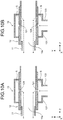
- the holes 121 are formed so as to gradually become closer to the inlet port 10a as the holes approach the inner surface of the pipe 12 from the outer surface thereof as illustrated in FIG. 2B in the first embodiment, a method of forming the holes 121 is not limited thereto.
- the holes 121 may be formed such that the positions of the holes 121 do not vary between the outer surface and the inner surface, for example.
- the holes 121 may be formed so as to gradually become farther from the inlet port 10a as the holes 121 approach the inner surface of the pipe 12 from the outer surface thereof.
- the hole formation mode illustrated in FIG. 2B and the hole formation mode illustrated in FIG. 10A or 10B may be mixed.
- the sizes of the holes 121 may not be necessarily constant.
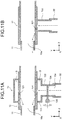
- a disc-like stopper 134 blocking a flow path of the cylinder portion 133 and a knob 135 for opening and closing the stopper 134 may be provided.
- the stopper 134 is coupled to the knob 135 and is supported on the cylinder portion 133 in a rotatable manner about the Z axis. When the knob 135 is turned, the stopper 134 rotates to open the flow path of the cylinder portion 133.
- the stopper 134 blocks travelling of the reagent gas mixture.
- the knob 135 is turned, the reagent gas mixture enters the closed space S and is inhaled by the subject. Accordingly, in this configuration example, turning the knob 135 triggers the start of inhalation of the gas mixture. The elapsed time until the cough is induced after the gas mixture starts to be inhaled can therefore be measured smoothly and accurately.
- the stopper 134 may be opened by a push-type switch.
- the employment of the switch can control opening and closing of the stopper 134 more easily.
- the stopper 134 may be controlled to be opened and closed electrically by an operation with buttons.
- opening and closing buttons may be provided on the testing instrument 10 or may be provided on the measuring unit 30 illustrated in FIG. 1 or the testing unit 40 illustrated in FIG. 5 .
- a cylinder portion 122 may be integrally formed on the lower surface of the pipe 12 and the holes 121 may be positioned in the cylinder portion 122 as illustrated in FIG. 11B .
- the hose 22 illustrated in FIG. 1 is coupled to the cylinder portion 122.
- the cover 13 is omitted, thereby reducing the number of components and simplifying the configuration.
- clogging of the holes 121 is more difficult to be prevented than in the first embodiment because it is difficult to clean the holes 121.
- the number of holes 121 is smaller than that in the above-mentioned first embodiment. This makes the reagent gas mixture difficult to be introduced to the inlet port 10a.
- the holes 121 are required to be increased in size in comparison with the above-mentioned first embodiment.
- the increase in size of the holes 121 causes the airflow of the cough to be easy to leak from the holes 121, and the cough detection accuracy may be lowered. In consideration of these circumstances in a comprehensive manner, it is considered that the configuration using the cover 13 as in the above-mentioned first embodiment is desirable.
- FIGS. 12A and 12B are a cross-sectional view of a constitution body obtained by integrating the cover 16 and the pipe 12 and corresponds to the cross-sectional view in FIG. 3 .
- FIG. 12A is a cross-sectional view of the cover 16 alone when the pipe 12 is removed from FIG. 12B .
- the cover 16 illustrated in FIG. 12A has a configuration in which wall portions 163 extending in the vertical direction are superimposed on the upper surfaces of a constituent body obtained by cutting the cover 13 illustrated in FIG. 2A along a plane that is parallel to the X-Z plane and contains the center axis L and then removing the upper portion of the cover 13.
- a flange portion 161 corresponds to the flange portion 131 of the cover 13 illustrated in FIG. 2
- a cylinder portion 162 corresponds to the cylinder portion 133 of the cover 13 illustrated in FIG. 2 .
- the flange portion 161 has only a lower semicircle portion, and the wall portions 163 are continuously provided above the flange portion 161.
- the flange portion 161 is also provided at the side facing in the negative direction of the Z-axis.
- a pressing plate 164 is supported on the upper surfaces of the wall portions 163 in a rotatable manner by a support axis 165. That is to say, the pressing plate 164 is rotatable about the support axis 165.
- a U-shaped cut 164a having a depth in the positive direction of the Z-axis is provided at an end portion of the pressing plate 164.
- the pressing plate 164 rotates forward (in the negative direction of the Z-axis)
- the cut 164a is engaged with a shaft portion of a fastening tool 166.
- a head portion is provided on the shaft portion of the fastening tool 166. Upward movement of the pressing plate 164 is therefore restricted.
- the upper surface of the cover 16 is opened by rotationally moving the pressing plate 164 backward (in the positive direction of the Z-axis).
- the pipe 12 is placed on the cover 16.
- the holes 121 are formed over the semi-circumference of the pipe 12.
- the pipe 12 is placed on the cover 16 such that a region with the holes 121 is located at the lower side.
- the pressing plate 164 is rotated forward (in the negative direction of the Z-axis) to cause the cut 164a to be engaged with the shaft portion of the fastening tool 166. With this engagement, the pipe 12 and the cover 16 are integrated with each other as illustrated in FIG. 12(b) .
- a flat surface 123 is formed on the upper surface of the pipe 12.
- the flat surface 123 is pressed by the pressing plate 164 such that the pipe 12 is positioned at a predetermined rotational position.
- the flat surface 123 is slightly higher than the lower surface of the pressing plate 164.
- the pipe 12 therefore receives downward force by the pressing plate 164 to be pressed against the cover 16.
- the closed space S is formed so as to cover the holes 121.
- the closed space S is filled with the gas mixture, and the gas mixture is guided into the pipe 12 through the holes 121. The subject then inhales the reagent gas mixture.
- the sizes of the holes 121 are constant in the above-mentioned embodiments, the sizes of the holes 121 may be changeable, and the mixed amount of the reagent may be controllable by changing the sizes of the holes 121.
- FIG. 13A illustrates a configuration example in which the sizes of the holes 121 are changeable.
- FIG. 13A illustrates, as a sectional view, only the configuration in the vicinity of the cover 13 in the testing instrument 10.
- FIG. 13A is a sectional view when the testing instrument 10 is evenly cut by a plane that is parallel to the Y-Z plane in the same manner as FIG. 2B .
- the pipe 12 in the first embodiment is changed to two cylindrical pipes 12a and 12b.
- the outer diameter of an end portion of the pipe 12b at the side facing in the negative direction of the Z-axis is substantially identical to the inner diameter of an end portion of the pipe 12a at the side facing in the positive direction of the Z-axis.
- the two pipes 12a and 12b are integrated with each other by fitting these two end portions with each other.
- the pipe 12a is rotatable about an axis parallel to the Z axis with respect to the pipe 12b.
- holes 121a and 121b that oppose each other in the combined state are formed in the pipes 12a and 12b, respectively.
- FIGS. 13B and 13C are cross-sectional views obtained by cutting the pipes 12a and 12b, which are combined as illustrated in FIG. 13A , along a plane parallel to the X-Y plane at a position of the holes 121a and 121b.
- the eight long holes 121a are formed evenly in the circumferential direction on the end portion of the pipe 12a that is fit with the end portion of the pipe 12b.
- the long holes 121a have contours elongated in the circumferential direction of the pipe 12a.
- eight long holes 121b are also formed evenly in the circumferential direction on the end portion of the pipe 12b that is fit with the end portion of the pipe 12a.
- the long holes 121b have contours elongated in the circumferential direction of the pipe 12b.
- the dimensions of the long holes 121a in the circumferential direction and the dimensions of the long holes 121b in the circumferential direction are the same.
- the long holes 121a completely match with the long holes 121b, and the sizes of the holes communicating between the closed space S and the inside of the pipes 12a and 12b illustrated in FIG. 13A are therefore maximum.
- the pipe 12a is rotated in the circumferential direction from this state as illustrated in FIG. 13C , overlapped portions of the long holes 121a and the long holes 121b are decreased.
- the sizes of the holes communicating between the closed space S and the inside of the pipes 12a and 12b illustrated in FIG. 13A are therefore made smaller than those in the case of FIG. 13B .
- the sizes of the holes communicating between the closed space S and the inside of the pipes 12a and 12b can be changed by rotating the pipe 12a in this manner.
- the mixed amount of the reagent can be desirably controlled by providing a changing mechanism for changing the sizes of the holes.
- the dimensions of the long holes 121a in the circumferential direction and the dimensions of the long holes 121b in the circumferential direction are the same in the configuration example of FIGS. 13A to 13C , the dimensions of the long holes 121a in the circumferential direction may be different from the dimensions of the long holes 121b in the circumferential direction.
- the eight long holes 121a formed in the pipe 12a may not have the same dimension in the circumferential direction.
- the eight long holes 121b formed in the pipe 12b may not have the same dimension in the circumferential direction.
- the number of the long holes 121a and 121b formed in the pipes 12a and 12b is not limited to eight and may be another number.
- Circular holes may be formed instead of the long holes 121a and 121b.
- Other desirable shapes, sizes, and arrangement positions of the holes may be employed as long as the overlap amount of the two holes can be changed by relatively rotating the pipes 12a and 12b in the circumferential direction.
- the overlap amount of the two long holes 121a and 121b is changed by relatively rotating the pipes 12a and 12b in the circumferential direction in the configuration example of FIGS. 13A to 13C
- the overlap amount of the two long holes 121a and 121b may be changed by relatively moving the pipes 12a and 12b in the lengthwise direction as illustrated in FIGS. 14A and 14B .
- the configuration example of FIGS. 14A and 14B can also change the sizes of the holes communicating between the closed space S and the inside of the pipes 12a and 12b in the same manner as the configuration example of FIGS. 13A to 13C .
- the mixed amount of the reagent can thereby be desirably controlled.
- the holes 121c and 121d may have contours elongated in the Z-axis direction or may have other shapes.
- other desirable shapes, sizes, and arrangement positions of the holes may be employed as long as the overlap amount of the two holes can be changed by relatively moving the pipes 12a and 12b in the lengthwise direction.
- a member that restricts a rotational movement range of the pipe 12a to a range in which the two long holes 121a and 121b oppose each other completely or at least partially is desirably provided. Furthermore, a guide member for rotating the pipe 12a in a state in which the two pipes 12a and 12b are completely fit with each other is desirably provided.
- a unit that restricts a movement range of the pipe 12a in the lengthwise direction to a range in which the two long holes 121c and 121d oppose each other completely or at least partially is desirably provided. Furthermore, a guide unit for moving the pipe 12a in the lengthwise direction in a state in which the two pipes 12a and 12b are not deviated from each other in the circumferential direction is desirably provided.
- the pipe 12, the support portion 141 of the filter member 14, and the cylindrical members 151a and 151b of the detector 15 are coupled to each other to configure the "pipe portion" described in the claims in the above-mentioned first embodiment, a method for configuring the "pipe portion” is not limited thereto.
- the "pipe portion” is not necessarily required to be configured by coupling other separate members and may be configured with one member.
- the "pipe portion” may be configured by coupling only the detector 15.
- the filter member 14 is effective for removing flown foreign bodies contained in the cough, it may be appropriately omitted from the configuration of the testing instrument 10 according to the invention.
- An arrangement position of the sensor 153 is not limited to the position in the first embodiment and can be appropriately changed to another position as long as the arrangement position is a position at which the strength of the subject's cough can be detected.
- the arrangement position of the filter member 14 can also be appropriately changed.
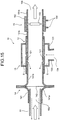
- the filter member 14 may be arranged between the inlet port 10a and the pipe 12 as illustrated in FIG. 15 .
- This arrangement enables the foreign bodies and the like contained in the cough to be prevented from adhering to the pipe 12 and the cover 13, thereby keeping the inside of the testing instrument 10 more hygienic.
- the filter member 14 is preferably arranged such that the filter 142 is close to the rear end of the inhalation tool 11 as much as possible. This arrangement enables the foreign bodies and the like to be prevented from adhering to the inside of the filter member 14.
- the filter 142 may be integrated with the inhalation tool 11. This causes the filter 142 to be also disposable together with the inhalation tool 11 but the inside of the testing instrument 10 can be hygienically kept more reliably.
- the sensor 153 may be arranged between the filter 142 and the pipe 12. In the configuration illustrated in FIG. 15 , the foreign bodies and the like contained in the cough do not adhere to the sensor 153 even when the sensor 153 is arranged between the filter 142 and the pipe 12 because the filter 142 is positioned at a just rear side of the inhalation tool 11.
- a display mode of the test result is not limited to the display modes illustrated in FIGS. 8A and 8B and can be appropriately modified.
- a waveform or the like of the cough, another parameter value, or the like may be added as a display target.
- the number, shapes, and sizes of the holes 121 can also be appropriately changed.
- the material of the testing instrument 10 is not limited to resin, and another material such as metal can also be used.
Landscapes
- Health & Medical Sciences (AREA)
- Life Sciences & Earth Sciences (AREA)
- Medical Informatics (AREA)
- Molecular Biology (AREA)
- Veterinary Medicine (AREA)
- Biophysics (AREA)
- Pathology (AREA)
- Engineering & Computer Science (AREA)
- Biomedical Technology (AREA)
- Heart & Thoracic Surgery (AREA)
- Physiology (AREA)
- Physics & Mathematics (AREA)
- Surgery (AREA)
- Animal Behavior & Ethology (AREA)
- General Health & Medical Sciences (AREA)
- Public Health (AREA)
- Pulmonology (AREA)
- Dentistry (AREA)
- Oral & Maxillofacial Surgery (AREA)
- Measurement Of The Respiration, Hearing Ability, Form, And Blood Characteristics Of Living Organisms (AREA)
- Investigating Or Analysing Biological Materials (AREA)
Description
- The present invention relates to a kit of parts comprising a testing instrument and a reagent supply unit, as well as to an airway protection testing apparatus that are used for testing an airway protection function.
- Currently, of the total number of patients in medical institutions, 1.6% patients are estimated to be under treatment for aspiration pneumonia. It is considered that mortality of patients who repeatedly contract aspiration pneumonia is high. In particular, mortality of elderly people due to aspiration pneumonia is extremely high. Conventionally, various methods for testing a swallowing state have been studied (for example,
Patent Literatures 1 and 2). -
- Patent Literature 1: Japanese Patent Application Laid-open No.
2013-017694 - Patent Literature 2: Japanese Patent Application Laid-open No.
2008-301895 -
JP S63-242228 A claim 1.DE 20 2011 005437 A1 - In general, aspiration is caused by a lowering of the sensitivity of the pharynx and a lowering of the ability to expel foreign bodies that are about to enter the airway. Accordingly, it is important in the prevention of aspiration pneumonia to test these elements. With the methods disclosed in
Patent Literatures 1 and 2 mentioned above, whether a swallowing operation functions properly is determined based on a change in the position of the pharynx and swallowing sound. These methods, however, cannot test the basic elements of aspiration that are the sensitivity of the pharynx and the ability to expel foreign bodies, i.e., the airway protection function cannot be tested. - In consideration of the above-mentioned problems, an object of the present invention is to provide a kit of parts comprising a testing instrument and a reagent supply unit, as well as an airway protection testing apparatus capable of easily and smoothly testing the airway protection function.
- A first aspect of the present invention relates to a kit of parts that is used for testing an airway protection function as defined in
claim 1. - With the kit of parts according to the aspect, when the reagent gas mixture is supplied from the inflow port, the gas mixture is guided to the holes and is further guided to the inlet port while passing through the inside of the pipe portion from the holes. Accordingly, a subject can inhale the reagent through the inlet port. When the reagent is inhaled, then, due to the reagent, the subject is induced to cough. When the subject coughs, airflow of the cough travels from the inlet port toward the outlet port while passing through the inside of the pipe portion. Strength of the thus induced cough can therefore be measured by disposing a sensor detecting the airflow of the cough that flows toward the outlet port. Time until the subject coughs can be measured manually or measured automatically based on output from the sensor. With the plurality of holes, the proper amount of reagent can be smoothly introduced into the pipe portion when the reagent is inhaled while reducing the size of the individual holes. Furthermore, the reduction in size of the individual holes can prevent the airflow generated by the subject's cough from leaking into the guide portion through the holes. The airflow of the cough can therefore be smoothly guided to the outlet port of the pipe portion, thereby measuring the strength of the cough with high accuracy.
- Usage of the kit of parts according to the first aspect enables elapsed time until induction of the cough and the strength of the cough to be measured simultaneously. The elapsed time corresponds to sharpness of the sensitivity of the pharynx, and the shorter elapsed time indicates the sharper sensitivity of the pharynx. The strength of the cough mainly corresponds to the ability to expel foreign bodies, and the stronger cough indicates the higher ability to expel foreign bodies. Thus, usage of the testing instrument according to the first aspect makes it easy and smooth to obtain information related to basic elements necessary for determining an airway protection function.
- The cough caused by using the kit of parts according to the first aspect is not a voluntary cough intended by the subject but an involuntary cough reflexively caused by the reagent. Measurement of the involuntary cough enables the sensitivity of the pharynx and the ability to expel foreign bodies to be grasped as the original airway protection function of the subject. Accordingly, the airway protection function of the subject can be properly diagnosed by using the kit of parts according to the first aspect.
- In the kit of parts according to the aspect, an inhalation tool to be held in the mouth of a subject may be installed on the inlet port in a detachable manner, for example. With this configuration, the inhalation tool can be appropriately replaced, thereby testing the airway protection function hygienically.
- The kit of parts according to the aspect may include a sensor for detecting strength of airflow that is discharged from the outlet port. With this configuration, time and effort for separately mounting a sensor on the testing instrument are eliminated.
- In the kit of parts according to the aspect, the guide portion can be detachable from the pipe portion. In this case, when the guide portion is mounted on the pipe portion, the closed space can be formed around the holes, and the closed space and the inflow port can communicate with each other.
- For example, the guide portion may have an opening into which the pipe portion is fit in a detachable manner, and has such a shape that, when the pipe portion is fit into the opening, the closed space is formed around the holes, and the closed space and the inflow port communicate with each other.
- When the guide portion is detachable from the pipe portion, the guide portion is appropriately detached from the pipe portion, and then the guide portion and the pipe portion can be cleaned by washing or the like. Accordingly, the testing instrument can be kept hygienic, and clogging of the holes can be prevented by cleaning.
- The holes may be formed so as to gradually become closer to the inlet port as the holes approach the inner surface of the pipe portion from the outer surface of the pipe portion. Thus, the reagent gas mixture can be made to smoothly travel toward the inlet port when the reagent is inhaled.
- Alternatively, the holes may be formed so as to gradually become farther from the inlet port as the holes approach the inner surface of the pipe portion from the outer surface of the pipe portion. Thus, airflow generated by the subject's cough is difficult to leak into the guide portion from the holes. The airflow of the cough can therefore be smoothly guided to the outlet port of the pipe portion, thereby measuring the strength of the cough with high accuracy.
- The kit of parts according to the aspect may further include: a stopper blocking a flow path continuous from the inflow port to the holes; and an opening and closing member opening and closing the stopper. With this configuration, timing at which the reagent is caused to travel to the inlet port can be controlled using the opening and closing member. The elapsed time until induction of the cough can therefore be measured more properly.
- A second aspect of the present invention relates to an airway protection testing apparatus as defined in
claim 10. - With the airway protection testing apparatus according to this aspect, a test is performed using the testing instrument according to the first aspect. Accordingly, the elapsed time until induction of the cough and the strength of the cough can be simultaneously measured as in the first aspect. This enables information related to the basic elements necessary for determining the airway protection function to be obtained easily and smoothly. Furthermore, the information based on the strength of the airflow is displayed on the display unit. This display enables a physician, an examiner, or the like to determine whether the subject has a disorder in the airway protection function by checking the display.
- In the airway protection testing apparatus according to the aspect, the measuring unit may further measure elapsed time until the airflow is generated in the outlet port after the gas mixture starts to be supplied to the inflow port, and the display unit may further display information based on the elapsed time. With this configuration, a physician, an examiner, or the like can simultaneously grasp the strength of the airflow generated by the cough and the elapsed time until induction of the cough by checking the display on the display unit. In addition, time and effort for measuring the elapsed time manually can be saved. Accordingly, whether the subject has the disorder in the airway protection function can be smoothly and easily determined.
- When the elapsed time until induction of the cough is further measured, the measuring unit may determine a risk of an airway protection disorder based on the strength of the airflow and the elapsed time, and the display unit may display information based on a determination result of the risk. With this configuration, the risk of the airway protection disorder can be easily grasped also in nursing and caring facility and the like in which there is no person who has expert knowledge, such as a physician and an examiner. Persons in charge in the nursing and caring facility and the like can therefore take measures of causing the subject having the risk of the airway protection disorder to undergo medical examination by a specialist and so on appropriately, thereby reducing the possibility that the subject suffers from aspiration pneumonia.
- The airway protection testing apparatus according to the aspect, the testing instrument, the reagent supply unit, the measuring unit, and the display unit may be accommodated in one housing. With this configuration, the airway protection testing apparatus can be easily carried and a test operation can be easily performed.
- As described above, the present invention can provide a kit of parts comprising a testing instrument and a reagent supply unit, as well as an airway protection testing apparatus capable of easily and smoothly testing an airway protection function.
- Characteristics of the present invention will be made clearer by the following description of embodiments.
- The following embodiments are merely modes for carrying out the present invention, and the present invention or the meanings of terminologies of its components are not limited by those described in the following embodiments.
-
-
FIG. 1 is a view illustrating the configuration of an airway protection testing apparatus according to a first embodiment. -
FIG. 2 includes a view illustrating the configurations of a pipe and a cover according to the first embodiment and a sectional view illustrating the configuration of a testing instrument. -
FIG. 3 is a cross-sectional view illustrating the configuration of the testing instrument according to the first embodiment. -
FIG. 4 includes tables illustrating test results obtained by the airway protection testing apparatus according to the first embodiment. -
FIG. 5 is a view illustrating the configuration of an airway protection testing apparatus according to a second embodiment. -
FIG. 6 is a diagram illustrating the configuration of the airway protection testing apparatus according to the second embodiment. -
FIG. 7 is a flowchart illustrating control of the airway protection testing apparatus according to the second embodiment. -
FIG. 8 includes views each illustrating an example of a display screen according to the second embodiment. -
FIG. 9 is a view illustrating the configuration of an airway protection testing apparatus according to a third embodiment. -
FIG. 10 includes sectional views each illustrating the configuration of a testing instrument according to a modification. -
FIG. 11 includes sectional views each illustrating the configuration of a testing instrument according to another modification. -
FIG. 12 includes cross-sectional views each illustrating the configuration of a testing instrument according to still another modification. -
FIG. 13 includes cross-sectional views and a sectional view each illustrating the configuration of a testing instrument according to still another modification. -
FIG. 14 includes sectional views each illustrating the configuration of a testing instrument according to still another modification. -
FIG. 15 is a sectional view illustrating the configuration of a testing instrument according to still another modification. - It should be noted that the drawings are provided merely for explanation and do not limit the scope of the present invention.
- Hereinafter, embodiments of the present invention will be described with reference to the drawings. An X axis, a Y axis, and a Z axis, which are orthogonal to one another, are added to the drawings for the convenience of description. The X axis and the Y axis are parallel to a horizontal plane and the Z axis is parallel to the vertical direction.
- In a first embodiment, a "pipe portion" described in the claims is constructed from a
pipe 12, asupport portion 141 of afilter member 14, andcylindrical members detector 15. Acover 13 in the first embodiment corresponds to a "guide portion" described in the claims, and areagent supply unit 20 and a measuringunit 30 correspond to a "reagent supply unit" and a "measuring unit" described in the claims, respectively. The first embodiment exemplifies a mode for carrying out the invention described in the claims and the invention described in the claims is not limited by correspondence between the configuration in the above-mentioned first embodiment and the configuration in the claims. -
FIG. 1 is a perspective view illustrating the configuration of an airwayprotection testing apparatus 1 according to the first embodiment. - As illustrated in
FIG. 1 , the airwayprotection testing apparatus 1 includes atesting instrument 10, thereagent supply unit 20, and the measuringunit 30. A reagent gas mixture is supplied to thetesting instrument 10 from thereagent supply unit 20. The reagent is tartaric acid, and the gas mixture, obtained by mixing droplets of tartaric acid with the air, is generated in thereagent supply unit 20. Thetesting instrument 10 includes aninhalation tool 11, thepipe 12, thecover 13, thefilter member 14, and thedetector 15. -
FIG. 2A is a view illustrating the configurations of thepipe 12 and thecover 13. - The
pipe 12 is made of a resin material and has a cylindrical shape. Thepipe 12 has a plurality ofholes 121 penetrating thepipe 12 from the outer surface to the inner surface. Theseholes 121 are formed so as to be aligned at a constant interval in the circumferential direction of thepipe 12. The plurality ofholes 121 are arranged in thepipe 12 evenly in the circumferential direction. - The
cover 13 is formed with a cylindrical member having an outer diameter that is larger than that of thepipe 12. Thecover 13 is also made of the resin material. The length of thecover 13 in the Z-axis direction is smaller than the length of thepipe 12 in the Z-axis direction.Flange portions 131 are provided on the respective end edges of thecover 13 at the sides facing in the negative and positive directions of the Z-axis so as to extend toward a center axis L of thecover 13. Acircular opening 132 is formed at the inner side of each of theflange portions 131. The center of eachopening 132 is identical to the center axis L of thecover 13. The diameter of eachopening 132 is substantially the same as the outer diameter of thepipe 12. - The
pipe 12 and thecover 13 are integrated with each other by fitting thepipe 12 into theopenings 132. Theintegrated cover 13 can be appropriately detached from thepipe 12. Acylinder portion 133 is formed on the lower surface of thecover 13. A space in thecylinder portion 133 communicates with a space in theopenings 132. The lower end of thecylinder portion 133 corresponds to aninflow port 13a for the reagent gas mixture. -
FIG. 2B is a sectional view when thetesting instrument 10 illustrated inFIG. 1 is evenly cut along a plane that is parallel to the Y-Z plane.FIG. 3 is a cross-sectional view cut along line A-A' inFIG. 2B . - As illustrated in
FIG. 2B , thecover 13 is mounted on thepipe 12 so as to cover theholes 121 from the outer side of thepipe 12. With this mounting, as illustrated inFIG. 2B andFIG. 3 , a closed space S is formed around theholes 121, and theinflow port 13a communicates with the closed space S. When the reagent gas mixture is introduced to theinflow port 13a, the closed space S is filled with the gas mixture, and the gas mixture is further guided into thepipe 12 from the closed space S through theholes 121. - The end edge of the
pipe 12 at the side facing in the negative direction of the Z-axis corresponds to aninlet port 10a for enabling a subject to inhale the gas mixture. As illustrated inFIG. 2B , thecylindrical inhalation tool 11 is fit into theinlet port 10a. Theinhalation tool 11 is made of, for example, a paper material having a predetermined thickness so as to be disposable. Alternatively, theinhalation tool 11 may be made of another material such as a resin material. - As illustrated in
FIG. 2B , in the first embodiment, theholes 121 are formed so as to gradually become closer to theinlet port 10a as theholes 121 approach the inner surface of thepipe 12 from the outer surface thereof. The gas mixture accumulated in the closed space S smoothly travels toward theinlet port 10a. - As illustrated in
FIG. 2B , thefilter member 14 is mounted on the end edge of thepipe 12 at the side facing in the positive direction of the Z-axis. Thefilter member 14 includes thesupport portion 141 and afilter 142. Thesupport portion 141 is made of a resin material and has such a shape that a center portion of a cylinder projects radially over the entire circumference. Thesupport portion 141 is configured by combining twocylindrical members FIG. 2B . The twocylindrical members support portion 141 pinch the outer circumferential portion of thefilter 142 such that thefilter 142 is supported by thesupport portion 141. The twocylindrical members filter 142 in this manner. A space in thesupport portion 141 is divided by thefilter 142 at a center portion in the Z-axis direction. Thefilter 142 filters the air flowing in the positive direction of the Z-axis in thesupport portion 141. - The inner diameter of the
support portion 141 at the side facing in the negative direction of the Z-axis is substantially the same as the inner diameter of thepipe 12. A step is provided on the end edge of thepipe 12 at the side facing in the positive direction of the Z-axis, and the end edge of thesupport portion 141 at the side facing in the negative direction of the Z-axis is fit into the step such that thefilter member 14 is integrated with thepipe 12. Theintegrated filter member 14 can be appropriately pulled out and detached from thepipe 12. - In addition, as illustrated in
FIG. 2B , thedetector 15 is mounted on the end edge of thesupport portion 141 at the side facing in the positive direction of the Z-axis. Thedetector 15 includes the twocylindrical members member 152 having a cylindrical shape. Thecylindrical members member 152 are made of a resin material. Furthermore, a predetermined support member supports asensor 153 detecting strength of airflow in the holdingmember 152. There is a space between the circumference of thesensor 153 and thecylindrical members sensor 153 is connected toterminals 154 with wirings (not illustrated). For example, a piezoelectric element is used as thesensor 153. - The
detector 15 is integrated with thefilter member 14 by fitting thecylindrical member 151b at the side facing in the negative direction of the Z-axis with an end portion of thesupport portion 141 at the side facing in positive direction the Z-axis. Thetesting instrument 10 illustrated inFIG. 1 is configured in this manner. As illustrated inFIG. 1 , agrip 155 is mounted on the lower surface of the holdingmember 152 so as to cover theterminals 154. - By referring to
FIG. 1 again, thereagent supply unit 20 generates the gas mixture obtained by mixing the fine droplets of tartaric acid with the air. Thereagent supply unit 20, for example, has the same function and configuration as those of an existing nebulizer. Thereagent supply unit 20, for example, generates fine droplets by the principle of spray with high-speed airflow or makes the reagent into droplets with an ultrasonic oscillator, and then generates the gas mixture by causing the droplets to flow on the air from a fan. - The
reagent supply unit 20 has a configuration in which anoperation input unit 211 and aspray unit 212 are provided on the upper surface of a box-shapedmain body 21. Thespray unit 212 discharges the gas mixture generated in thereagent supply unit 20. Thespray unit 212 is coupled to thecylinder portion 133 of thecover 13 with ahose 22. The gas mixture generated in thereagent supply unit 20 is thereby supplied to the inside of thecover 13. - The measuring
unit 30 has a configuration in which adisplay unit 311 and anoperation input unit 312 are provided on the upper surface of a box-shapedmain body 31. The measuringunit 30 is coupled to the terminals 154 (seeFIG. 2B ) of thedetector 15 via acable 32. Thecable 32 is connected to theterminals 154 while passing through the inside of thegrip 155. The measuringunit 30 includes a signal processing circuit (not illustrated) such as a central processing unit (CPU) therein, measures strength of a cough induced on the subject based on a detection signal of the sensor 153 (seeFIG. 2B ), and causes thedisplay unit 311 to display a measurement result. The strength of the cough is measured using what is called a peak cough flow (PCF). - For example, an existing spirometer can be used as the
filter member 14, thedetector 15, and the measuringunit 30. The existing spirometer measures various measurement items other than the strength of a cough (PCF) as a measurement target in the first embodiment and therefore has excessive specification in the first embodiment. It is sufficient that the measuringunit 30 has a configuration and function capable of measuring at least the strength of a cough based on output from thesensor 153. - As illustrated in
FIG. 1 , when the subject inhales the air by holding theinhalation tool 11 with his (her) mouth, the gas mixture filling the closed space S passes through theholes 121 and is introduced into thepipe 12 as indicated by arrows with dashed-dotted lines inFIG. 2B . Furthermore, the gas mixture is guided to theinlet port 10a while passing through the inside of thepipe 12, and is inhaled by the subject through theinhalation tool 11. Thus, the inhalation of the reagent induces the subject to cough. When the subject coughs, airflow of the cough travels from theinlet port 10a toward anoutlet port 10b while passing through the inside of thepipe 12. In this case, thefilter 142 removes foreign bodies such as saliva that are contained in the cough. Thesensor 153 outputs a detection signal in accordance with the strength of the cough to the measuringunit 30. The measuringunit 30 measures the strength of the cough (PCF) based on the detection signal, and a measurement result is displayed on thedisplay unit 311. The airflow of the cough that has passed through thesensor 153 is discharged through theoutlet port 10b. - In the first embodiment, a physician or the examiner manually measures elapsed time until the subject coughs after the
reagent supply unit 20 supplies the gas mixture to thecover 13. The physician or examiner determines an airway protection function of the subject based on the measured elapsed time and the strength of the cough (PCF) displayed on thedisplay unit 311. - The inventors of the present application performed a test of the airway protection function on a plurality of subjects using the airway
protection testing apparatus 1 having the above-mentioned configuration. In the test, an existing nebulizer was used as thereagent supply unit 20 and an existing spirometer was used as thefilter member 14, thedetector 15, and the measuringunit 30. The test was performed on each subject with the following procedures. - (1) A nose clip is mounted on each subject so as to prevent a cough from leaking from his (her) nose.
- (2) The reagent supply unit 20 (nebulizers) is filled with a tartaric acid solution at a concentration of 20%, and the gas mixture starts to be sprayed.
- (3) Measurement with the spirometer is started.
- (4) The
inhalation tool 11 of thetesting instrument 10 is fit into the mouth of the subject, and inhalation is started. - (5) Time until the subject is induced to cough from the start of the inhalation is measured manually.
- (6) Strength of the induced cough (PCF) and a forced vital capacity (FVC) are obtained as measurement results.
-
FIGS. 4A and 4B indicate test results of the test.FIG. 4(a) indicates the test results when the subjects were healthy individuals andFIG. 4B indicates the test results when the subjects had past histories of aspiration pneumonia. - As illustrated in
FIG. 4A , when the subjects were healthy individuals, the elapsed time until induction of a cough was 1 second for all of the subjects. As a result, it can be evaluated that all of these subjects had sharp sensitivity of the pharynx. When the subjects were healthy individuals, the minimum of the PCFs, each of which indicates the strength of the cough, was 2.5 liters/sec among all of the subjects. As a result, it can be evaluated that all of these subjects had high abilities to expel foreign bodies. Accordingly, this test provided the test results indicating that when the subjects were healthy individuals, all of the subjects had preferable airway protection functions. - Alternatively, as illustrated in
FIG. 4B , when the subjects had the past histories of pneumonia, the elapsed time until induction of the cough was over 20 seconds for each of the subjects. As a result, it can be evaluated that all of these subjects were in states in which their sensitivities of the pharynx were lowered. When the subjects had the past histories of aspiration pneumonia, the PCF indicating the strength of the cough was lower than 0.5 liter/sec for each of the subjects. As a result, it can be evaluated that all of these subjects had low abilities to expel foreign bodies. Accordingly, this test provided the test results indicating that when the subjects had the past histories of aspiration pneumonia, the airway protection functions of all of the subjects were significantly lowered. - Usage of the airway
protection testing apparatus 1 having the above-mentioned configuration enables parameter values (induction time of a cough and strength of the cough) in accordance with medical conditions to be obtained. The airway protection function can be properly diagnosed by using the airwayprotection testing apparatus 1 having the above-mentioned configuration. - In the above-described test, the PCF and the FVC were used as the evaluation parameters. Alternatively, evaluation parameters other than them can be appropriately used.
- The configuration of the first embodiment can provide the following effects.
- Usage of the
testing instrument 10 can simultaneously measure elapsed time until induction of a cough and strength of the cough. The cough caused by using thetesting instrument 10 is not a voluntary cough intended by the subject but an involuntary cough reflexively caused by a reagent. The involuntary cough can be measured by using thetesting instrument 10, thereby grasping the sensitivity of the pharynx and the ability to expel foreign bodies as an original airway protection function of the subject. Accordingly, the airway protection function of the subject can be properly diagnosed by using thetesting instrument 10. - As illustrated in
FIG. 2B , theinhalation tool 11 to be held in the mouth of the subject is installed on theinlet port 10a in a detachable manner. With this configuration, theinhalation tool 11 can be appropriately replaced, thereby testing the airway protection function hygienically. - As illustrated in
FIGS. 2A and 2B , thecover 13 is detachable from thepipe 12. Thecover 13 can therefore be detached from thepipe 12 appropriately, and then thecover 13 and thepipe 12 can be cleaned by washing or the like. Accordingly, thetesting instrument 10 can be kept hygienic, and clogging of theholes 121 can be prevented by cleaning. - As illustrated in
FIG. 2A , theholes 121 are formed in thepipe 12. The proper amount of reagent can therefore be smoothly introduced into thepipe 12 when the reagent is inhaled while reducing the size of the individual holes 121. Furthermore, the reduction in size of theindividual holes 121 can prevent airflow generated by the subject's cough from leaking into thecover 13 through theholes 121. The airflow of the cough can therefore be smoothly guided to theoutlet port 10b, thereby measuring the strength of the cough with high accuracy. - As illustrated in
FIGS. 2A and 2B , theholes 121 are formed so as to gradually become closer to theinlet port 10a as theholes 121 approach the inner surface of thepipe 12 from the outer surface thereof. Thus, the reagent gas mixture can be made to smoothly travel toward theinlet port 10a when the reagent is inhaled. - The PCF indicating the strength of the cough is displayed on the
display unit 311 of the measuringunit 30. This display enables a physician, an examiner, or the like to determine whether the subject has a disorder in the airway protection function by checking the display. - In the first embodiment, the
reagent supply unit 20 and the measuringunit 30 are configured as the separate bodies. In a second embodiment, they are integrated with each other as one unit. -
FIG. 5 is a perspective view illustrating the configuration of the airwayprotection testing apparatus 1 according to the second embodiment. - As illustrated in
FIG. 5 , thetesting instrument 10 has the same configuration as that in the above-described first embodiment. Atesting unit 40 has a configuration in which adisplay unit 411, anoperation input unit 412, and aspray unit 413 are provided on the upper surface of a box-shapedmain body 41. Aspeaker 414 is provided on the side surface of themain body 41. Thetesting unit 40 is coupled to the terminals 154 (seeFIG. 2B ) of thedetector 15 via acable 43. Thecable 43 is connected to theterminals 154 while passing through the inside of thegrip 155. Thespray unit 413 discharges a reagent gas mixture that is generated in themain body 41. Thespray unit 413 is coupled to thecylinder portion 133 of thecover 13 with ahose 42. The gas mixture generated in thetesting unit 40 is thereby supplied into thecover 13. -
FIG. 6 is a diagram illustrating the block configuration of the airwayprotection testing apparatus 1 according to the second embodiment. - As illustrated in
FIG. 6 , thetesting unit 40 includes acontroller 401, areagent supply unit 402, and ameasuring unit 403 in addition to thedisplay unit 411, theoperation input unit 412, and thespeaker 414. Thereagent supply unit 402 includes thespray unit 413. - The
controller 401 includes a processing unit such as a CPU and astorage 401a. Thestorage 401a includes a storage device such as a read only memory (ROM) and a random access memory (RAM). Thecontroller 401 controls each unit in accordance with a control program stored in thestorage 401a. Thestorage 401a stores therein the above-mentioned control program and is used as a work area when the control program is executed. - The
reagent supply unit 402 nebulizes the reagent (tartaric acid solution) contained in areagent container 402a to generate the gas mixture obtained by mixing droplets of the reagent with the air. Thereagent supply unit 402, for example, generates fine droplets based on the principle of spray using high-speed airflow, or makes the reagent into droplets by an ultrasonic oscillator to generate the gas mixture by causing the droplets to flow on the air from a fan. - The measuring
unit 403 starts a time counting operation in accordance with an instruction from thecontroller 401 and measures elapsed time until the subject is induced to cough after the reagent starts to be supplied. In this case, the measuringunit 403 detects the induction of the cough based on a detection signal from the detector 15 (sensor 153). The measuringunit 403 measures strength of the induced cough (PCF) with the detection signal from the detector 15 (sensor 153) in accordance with an instruction from thecontroller 401. When detecting the induction of the cough based on the detection signal from the detector 15 (sensor 153), the measuringunit 403 outputs information indicating the measured elapsed time and the strength of the cough (PCF) to thecontroller 401. - In the cough measuring operation, the measuring
unit 403 calculates a flow rate (liters/sec) of the cough flowing toward theoutlet port 10b in thedetector 15, for example, based on the detection signal from thesensor 153. The measuringunit 403 determines that the cough has been induced when the flow rate is higher than a predetermined threshold, and a period of time until the flow rate is lower than the threshold again is set to a coughing period. The measuringunit 403 detects a maximum value (peak value) of the flow rate during the coughing period set in this manner as the strength of the cough (PCF). A change speed of the detection signal from thesensor 153 may be obtained as the flow rate of the cough. -
FIG. 7 is a flowchart illustrating control of the airway protection testing apparatus according to the second embodiment.FIG. 7 is a flowchart illustrating measurement processing in the second embodiment. The measurement processing is performed after the nose clip is mounted on the subject and the subject holds theinhalation tool 11 of thetesting instrument 10 with his (her) mouth as measurement preparation operations. - When a measurement start instruction is input through the operation input unit 412 (YES at S11), the
controller 401 causes the measuringunit 403 to start measurement of elapsed time and measurement of a cough (S12). Simultaneously with this, thecontroller 401 causes thereagent supply unit 402 to start to spray the reagent (S13). Thecontroller 401 continues these operations until the measuringunit 403 detects the cough (S14). - Thereafter, when the subject is induced to cough and the
controller 401 receives the information indicating the elapsed time and the strength of the cough from the measuringunit 403, thecontroller 401 determines that the cough has been detected (YES at S14) and causes thereagent supply unit 402 to finish to spray the reagent (S15). Thecontroller 401 controls to store the received the information indicating the elapsed time and the strength of the cough in thestorage 401a and causes thedisplay unit 411 to display the information (S16). Furthermore, thecontroller 401 refers to the received elapsed time and strength of the cough and determines whether the elapsed time is equal to or longer than a predetermined threshold Ts and the strength of the cough is equal to or weaker than a predetermined threshold Ps (S17). When the condition is satisfied (YES at S17), thecontroller 401 adds information indicating that the subject has a risk of an airway protection disorder onto a screen on the display unit 411 (S18). Alternatively, when the above-mentioned condition is not satisfied (NO at S17), thecontroller 401 adds information indicating that the subject has no risk of the airway protection disorder onto the screen on the display unit 411 (S19). -
FIGS. 8A and 8B are views indicating the screens on thedisplay unit 411 when the respective pieces of processing at S18 and S19 are performed. - As illustrated in
FIG. 8A , when the condition that the elapsed time measured by the measuringunit 403 is equal to or longer than the predetermined threshold Ts and the strength of the cough is equal to or weaker than the predetermined threshold Ps is satisfied, display D1 indicating the elapsed time (time) and the strength of the cough (PCF) and display D2 indicating that the subject has the risk of the airway protection disorder are displayed on thedisplay unit 411. By contrast, when the condition that the elapsed time measured by the measuringunit 403 is equal to or longer than the predetermined threshold Ts and the strength of the cough is equal to or weaker than the predetermined threshold Ps is not satisfied, the display D1 and display D3 indicating that the subject has no risk of the airway protection disorder are displayed on thedisplay unit 411. These displays enable a physician, an examiner, or the like to easily determine whether the subject has the risk of the airway protection disorder. - The second embodiment also provides the same effects as those provided in the first embodiment. In addition, the second embodiment can provide the following effects.
- The measuring
unit 403 measures elapsed time until induction of a cough after a reagent starts to be sprayed. Time and effort for measuring the elapsed time manually can therefore be saved. Furthermore, the elapsed time (time) and the strength of the cough (PCF) are displayed on thedisplay unit 411. This display enables a physician, an examiner, or the like to simultaneously grasp the strength of the cough and the elapsed time until the induction of the cough and to smoothly and easily determine whether the subject has the disorder in the airway protection function by checking the display on thedisplay unit 411. - In addition, in the second embodiment, as illustrated in
FIGS. 8A and 8B , the screen contains the displays D2 and D3 regarding the risk of the airway protection disorder. With this display, the risk of the airway protection disorder can be easily grasped also in nursing and caring facility and the like in which there is no person who has expert knowledge, such as a physician and an examiner. Persons in charge in the nursing and caring facility and the like can therefore take measures of causing the subject having the risk of the airway protection disorder to undergo medical examination by a specialist and so on appropriately, thereby reducing the possibility that the subject suffers from aspiration pneumonia. - Furthermore, as illustrated in
FIG. 5 , the constituent units other than thetesting instrument 10 are intensively installed in onetesting unit 40. With this configuration, the airwayprotection testing apparatus 1 can be easily carried and a test operation can also be easily performed. - In the flowchart illustrated in
FIG. 7 , the pieces of processing at S17 to S19 may be omitted. In this case, the displays D2 and D3 are omitted fromFIGS. 8(a) and 8(b) . Also in this case, persons who have the expert knowledge, such as a physician and an examiner, can determine whether the subject has the risk of the airway protection disorder based on the display D1. In this case, persons who do not have the expert knowledge, such as persons in charge in the nursing and caring facility, cannot determine whether the subject has the risk of the airway protection disorder based on the display D1. This mode is therefore considered to be useful when the airwayprotection testing apparatus 1 is used in medical institution. - Alternatively, in the flowchart illustrated in
FIG. 7 , the display processing at S16 may be omitted. In this case, the display D1 is omitted fromFIGS. 8A and 8B . Not only persons who have the expert knowledge, such as a physician and an examiner, but also persons in charge in the nursing and caring facility can determine whether the subject has the risk of the airway protection disorder based on the displays D2 and D3. In this case, a physician, an examiner, or the like cannot determine the level of the airway protection disorder of the subject because there is no display D1. This mode is therefore considered to be useful when the airwayprotection testing apparatus 1 is used in non-medical institution. - Although the test results are displayed on the
display unit 411 in the flowchart inFIG. 7 , sound indicating a display result may be output from thespeaker 414 in addition to the display or instead of the display. For example, predetermined warning sound may be output from thespeaker 414 only in the processing at S18 or different types of sound may be output from thespeaker 414 in the processing at S18 and the processing at S19. Alternatively, announcement reading notifications corresponding to displays in the pieces of processing at S18 and S19 may be output from thespeaker 414. - The condition for determining whether the subject has the risk of the airway protection disorder is set to the condition indicated by the processing at S17 in the flowchart in
FIG. 7 . However, conditions other than that may be used. For example, a method in which it is determined that the subject has the risk of the airway protection disorder when the elapsed time is significantly long or a method in which it is determined that the subject has the risk of the airway protection disorder when the strength of the cough is significantly weak may be used together with the determination condition indicated by the processing at S17 or instead of the determination condition indicated by the processing at S17. Alternatively, whether the subject has the risk of the airway protection disorder may be determined by comparing a value, which is obtained by substituting the elapsed time and the strength of the cough into a predetermined expression, with a threshold. - In the second embodiment, the
testing instrument 10 and thetesting unit 40 are configured as the separate bodies. In a third embodiment, they are integrated with each other as one unit. -
FIG. 9 is a perspective view illustrating the configuration of the airwayprotection testing apparatus 1 according to the third embodiment. - As illustrated in
FIG. 9 , amain body 50 of the airwayprotection testing apparatus 1 is constructed from a box-shapedhousing 50a. Adisplay unit 511 and anoperation input unit 512 are provided on the upper surface of themain body 50, and aspeaker 513 is provided on the side surface of themain body 50. Furthermore,circular holes main body 50, the side surfaces facing in the positive and negative directions of the Z-axis, respectively. - The
testing instrument 10 is accommodated in thehousing 50a. Thetesting instrument 10 has, for example, a configuration in which thegrip 155 is omitted from the configuration illustrated inFIG. 1 . Theinlet port 10a of thetesting instrument 10 is exposed to the outside through thehole 514, and theoutlet port 10b of thetesting instrument 10 is exposed to the outside through thehole 515. Aninhalation tool 60 is fit into theinlet port 10a in a detachable manner. Thetesting instrument 10 is desirably detachable from thehousing 50a by, for example, opening the upper surface of thehousing 50a. - Constituent blocks corresponding to the
controller 401, thestorage 401a, thereagent supply unit 402, thereagent container 402a, and the measuringunit 403 illustrated inFIG. 6 are accommodated in thehousing 50a. These components are appropriately connected to each other with pipes or wirings in thehousing 50a. Also in the third embodiment, the same control as that illustrated inFIG. 7 and the same display as that illustrated inFIG. 8 are performed. A test start instruction is input by, for example, pushing, by the subject, a start button on theoperation input unit 512 with his (her) finger. - The third embodiment also provides the same effects as those provided in the second embodiment.
- In addition, with the third embodiment, the
testing instrument 10 and thetesting unit 40 are integrated with each other as one unit. The airwayprotection testing apparatus 1 can therefore be carried more easily and a test operation can be performed more easily than in the second embodiment. - In the third embodiment, as illustrated in
FIG. 9 , the airwayprotection testing apparatus 1 and a face of the subject are close to each other, thereby arranging a detection unit for detecting that the subject has held theinhalation tool 60 with his (her) mouth on the airwayprotection testing apparatus 1. An optical sensor, a miniature camera, or the like can be used as the detection unit. When such a detection unit is arranged, spray of a reagent, measurement of elapsed time, and detection of a cough may be started in response to the detection that the subject has held theinhalation tool 60 with his (her) mouth. The airway protection function of the subject can thereby be diagnosed more easily with high accuracy. - Although the embodiments of the present invention have been described hereinbefore, the above-mentioned embodiments do not limit the present invention and the embodiments of the present invention can also be variously changed.
- For example, although the
holes 121 are formed so as to gradually become closer to theinlet port 10a as the holes approach the inner surface of thepipe 12 from the outer surface thereof as illustrated inFIG. 2B in the first embodiment, a method of forming theholes 121 is not limited thereto. As illustrated inFIG. 10A , theholes 121 may be formed such that the positions of theholes 121 do not vary between the outer surface and the inner surface, for example. Alternatively, as illustrated inFIG. 10B , theholes 121 may be formed so as to gradually become farther from theinlet port 10a as theholes 121 approach the inner surface of thepipe 12 from the outer surface thereof. The hole formation mode illustrated inFIG. 2B and the hole formation mode illustrated inFIG. 10A or 10B may be mixed. The sizes of theholes 121 may not be necessarily constant. - When the
holes 121 are formed as illustrated inFIG. 10B , airflow generated by a cough of the subject is difficult to leak into the cover 13 (closed space S) through theholes 121. The airflow of the cough can therefore be smoothly introduced to theoutlet port 10b, thereby detecting strength of the cough with high accuracy. - As illustrated in
FIG. 11A , a disc-like stopper 134 blocking a flow path of thecylinder portion 133 and aknob 135 for opening and closing thestopper 134 may be provided. In the configuration inFIG. 11A , thestopper 134 is coupled to theknob 135 and is supported on thecylinder portion 133 in a rotatable manner about the Z axis. When theknob 135 is turned, thestopper 134 rotates to open the flow path of thecylinder portion 133. - With this configuration, even when the
reagent supply unit 20 starts a reagent spray operation, thestopper 134 blocks travelling of the reagent gas mixture. When the subject holds theinhalation tool 11 with his (her) mouth, and then, theknob 135 is turned, the reagent gas mixture enters the closed space S and is inhaled by the subject. Accordingly, in this configuration example, turning theknob 135 triggers the start of inhalation of the gas mixture. The elapsed time until the cough is induced after the gas mixture starts to be inhaled can therefore be measured smoothly and accurately. - Although in the configuration example illustrated in
FIG. 11A , turning theknob 135 causes thestopper 134 to be opened, thestopper 134 may be opened by a push-type switch. The employment of the switch can control opening and closing of thestopper 134 more easily. Furthermore, thestopper 134 may be controlled to be opened and closed electrically by an operation with buttons. In this case, opening and closing buttons may be provided on thetesting instrument 10 or may be provided on the measuringunit 30 illustrated inFIG. 1 or thetesting unit 40 illustrated inFIG. 5 . - Although the
pipe 12 and thecover 13 are configured as the separate bodies and can be detachable from each other as illustrated inFIGS. 2A and 2B in the first embodiment, acylinder portion 122 may be integrally formed on the lower surface of thepipe 12 and theholes 121 may be positioned in thecylinder portion 122 as illustrated inFIG. 11B . In this case, thehose 22 illustrated inFIG. 1 is coupled to thecylinder portion 122. - With this configuration, the
cover 13 is omitted, thereby reducing the number of components and simplifying the configuration. However, clogging of theholes 121 is more difficult to be prevented than in the first embodiment because it is difficult to clean theholes 121. Furthermore, the number ofholes 121 is smaller than that in the above-mentioned first embodiment. This makes the reagent gas mixture difficult to be introduced to theinlet port 10a. For this reason, theholes 121 are required to be increased in size in comparison with the above-mentioned first embodiment. The increase in size of theholes 121 causes the airflow of the cough to be easy to leak from theholes 121, and the cough detection accuracy may be lowered. In consideration of these circumstances in a comprehensive manner, it is considered that the configuration using thecover 13 as in the above-mentioned first embodiment is desirable. - Although the
cover 13 and thepipe 12 are integrated with each other by fitting thepipe 12 into theopenings 132 of thecover 13 in the above-mentioned first embodiment, a method for integrating thecover 13 and thepipe 12 is not limited thereto. For example, acover 16 illustrated inFIGS. 12A and 12B may be used instead of thecover 13.FIG. 12B is a cross-sectional view of a constitution body obtained by integrating thecover 16 and thepipe 12 and corresponds to the cross-sectional view inFIG. 3 .FIG. 12A is a cross-sectional view of thecover 16 alone when thepipe 12 is removed fromFIG. 12B . - The
cover 16 illustrated inFIG. 12A has a configuration in whichwall portions 163 extending in the vertical direction are superimposed on the upper surfaces of a constituent body obtained by cutting thecover 13 illustrated inFIG. 2A along a plane that is parallel to the X-Z plane and contains the center axis L and then removing the upper portion of thecover 13. Aflange portion 161 corresponds to theflange portion 131 of thecover 13 illustrated inFIG. 2 , and acylinder portion 162 corresponds to thecylinder portion 133 of thecover 13 illustrated inFIG. 2 . Theflange portion 161 has only a lower semicircle portion, and thewall portions 163 are continuously provided above theflange portion 161. In the same manner asFIG. 2A , theflange portion 161 is also provided at the side facing in the negative direction of the Z-axis. - A
pressing plate 164 is supported on the upper surfaces of thewall portions 163 in a rotatable manner by asupport axis 165. That is to say, thepressing plate 164 is rotatable about thesupport axis 165. AU-shaped cut 164a having a depth in the positive direction of the Z-axis is provided at an end portion of thepressing plate 164. When thepressing plate 164 rotates forward (in the negative direction of the Z-axis), thecut 164a is engaged with a shaft portion of afastening tool 166. A head portion is provided on the shaft portion of thefastening tool 166. Upward movement of thepressing plate 164 is therefore restricted. - When the
pipe 12 and thecover 16 are integrated with each other, the upper surface of thecover 16 is opened by rotationally moving thepressing plate 164 backward (in the positive direction of the Z-axis). In this state, thepipe 12 is placed on thecover 16. Theholes 121 are formed over the semi-circumference of thepipe 12. Thepipe 12 is placed on thecover 16 such that a region with theholes 121 is located at the lower side. Thereafter, thepressing plate 164 is rotated forward (in the negative direction of the Z-axis) to cause thecut 164a to be engaged with the shaft portion of thefastening tool 166. With this engagement, thepipe 12 and thecover 16 are integrated with each other as illustrated inFIG. 12(b) . - As illustrated in
FIG. 12B , in this configuration example, aflat surface 123 is formed on the upper surface of thepipe 12. Theflat surface 123 is pressed by thepressing plate 164 such that thepipe 12 is positioned at a predetermined rotational position. In this case, theflat surface 123 is slightly higher than the lower surface of thepressing plate 164. Thepipe 12 therefore receives downward force by thepressing plate 164 to be pressed against thecover 16. When thepipe 12 and thecover 16 are integrated with each other in this manner, the closed space S is formed so as to cover theholes 121. When the reagent gas mixture flows into the closed space S from thecylinder portion 162, the closed space S is filled with the gas mixture, and the gas mixture is guided into thepipe 12 through theholes 121. The subject then inhales the reagent gas mixture. - Although the sizes of the
holes 121 are constant in the above-mentioned embodiments, the sizes of theholes 121 may be changeable, and the mixed amount of the reagent may be controllable by changing the sizes of theholes 121. -
FIG. 13A illustrates a configuration example in which the sizes of theholes 121 are changeable.FIG. 13A illustrates, as a sectional view, only the configuration in the vicinity of thecover 13 in thetesting instrument 10.FIG. 13A is a sectional view when thetesting instrument 10 is evenly cut by a plane that is parallel to the Y-Z plane in the same manner asFIG. 2B . - As illustrated in
FIG. 13A , in this configuration example, thepipe 12 in the first embodiment is changed to twocylindrical pipes pipe 12b at the side facing in the negative direction of the Z-axis is substantially identical to the inner diameter of an end portion of thepipe 12a at the side facing in the positive direction of the Z-axis. The twopipes pipe 12a is rotatable about an axis parallel to the Z axis with respect to thepipe 12b. Furthermore,holes pipes -
FIGS. 13B and 13C are cross-sectional views obtained by cutting thepipes FIG. 13A , along a plane parallel to the X-Y plane at a position of theholes - As illustrated in
FIG. 13B , the eightlong holes 121a are formed evenly in the circumferential direction on the end portion of thepipe 12a that is fit with the end portion of thepipe 12b. Thelong holes 121a have contours elongated in the circumferential direction of thepipe 12a. In the same manner, eightlong holes 121b are also formed evenly in the circumferential direction on the end portion of thepipe 12b that is fit with the end portion of thepipe 12a. Thelong holes 121b have contours elongated in the circumferential direction of thepipe 12b. In this configuration example, the dimensions of thelong holes 121a in the circumferential direction and the dimensions of thelong holes 121b in the circumferential direction are the same. - In the state illustrated in
FIG. 13A , thelong holes 121a completely match with thelong holes 121b, and the sizes of the holes communicating between the closed space S and the inside of thepipes FIG. 13A are therefore maximum. When thepipe 12a is rotated in the circumferential direction from this state as illustrated inFIG. 13C , overlapped portions of thelong holes 121a and thelong holes 121b are decreased. The sizes of the holes communicating between the closed space S and the inside of thepipes FIG. 13A are therefore made smaller than those in the case ofFIG. 13B . - In this configuration example, the sizes of the holes communicating between the closed space S and the inside of the
pipes pipe 12a in this manner. The mixed amount of the reagent can be desirably controlled by providing a changing mechanism for changing the sizes of the holes. - Although the dimensions of the
long holes 121a in the circumferential direction and the dimensions of thelong holes 121b in the circumferential direction are the same in the configuration example ofFIGS. 13A to 13C , the dimensions of thelong holes 121a in the circumferential direction may be different from the dimensions of thelong holes 121b in the circumferential direction. Furthermore, the eightlong holes 121a formed in thepipe 12a may not have the same dimension in the circumferential direction. Similarly, the eightlong holes 121b formed in thepipe 12b may not have the same dimension in the circumferential direction. Moreover, the number of thelong holes pipes long holes pipes - Although the overlap amount of the two
long holes pipes FIGS. 13A to 13C , the overlap amount of the twolong holes pipes FIGS. 14A and 14B . - In the configuration example of
FIGS. 14A and 14B , in a state in which the end portion of thepipe 12a at the side facing in the positive direction of the Z-axis and the end portion of thepipe 12b at the side facing in the negative direction of the Z-axis are completely fit with each other as illustrated inFIG. 14A , holes 121c in thepipe 12a andholes 121d in thepipe 12b completely match with each other. From this state, when thepipe 12a is moved in the negative direction of the Z-axis as illustrated inFIG. 14B , the overlap amount of the twolong holes pipes FIG. 14A . - In this manner, the configuration example of
FIGS. 14A and 14B can also change the sizes of the holes communicating between the closed space S and the inside of thepipes FIGS. 13A to 13C . The mixed amount of the reagent can thereby be desirably controlled. Theholes FIGS. 13A to 13C , other desirable shapes, sizes, and arrangement positions of the holes may be employed as long as the overlap amount of the two holes can be changed by relatively moving thepipes - In the configuration example of
FIGS. 13A to 13C , a member that restricts a rotational movement range of thepipe 12a to a range in which the twolong holes pipe 12a in a state in which the twopipes - In the configuration example of
FIGS. 14A and 14B , a unit that restricts a movement range of thepipe 12a in the lengthwise direction to a range in which the twolong holes pipe 12a in the lengthwise direction in a state in which the twopipes - Although the
pipe 12, thesupport portion 141 of thefilter member 14, and thecylindrical members detector 15 are coupled to each other to configure the "pipe portion" described in the claims in the above-mentioned first embodiment, a method for configuring the "pipe portion" is not limited thereto. For example, the "pipe portion" is not necessarily required to be configured by coupling other separate members and may be configured with one member. Furthermore, the "pipe portion" may be configured by coupling only thedetector 15. - Although the
filter member 14 is effective for removing flown foreign bodies contained in the cough, it may be appropriately omitted from the configuration of thetesting instrument 10 according to the invention. An arrangement position of thesensor 153 is not limited to the position in the first embodiment and can be appropriately changed to another position as long as the arrangement position is a position at which the strength of the subject's cough can be detected. The arrangement position of thefilter member 14 can also be appropriately changed. - For example, the
filter member 14 may be arranged between theinlet port 10a and thepipe 12 as illustrated inFIG. 15 . This arrangement enables the foreign bodies and the like contained in the cough to be prevented from adhering to thepipe 12 and thecover 13, thereby keeping the inside of thetesting instrument 10 more hygienic. In this case, thefilter member 14 is preferably arranged such that thefilter 142 is close to the rear end of theinhalation tool 11 as much as possible. This arrangement enables the foreign bodies and the like to be prevented from adhering to the inside of thefilter member 14. Thefilter 142 may be integrated with theinhalation tool 11. This causes thefilter 142 to be also disposable together with theinhalation tool 11 but the inside of thetesting instrument 10 can be hygienically kept more reliably. - In the configuration illustrated in
FIG. 15 , thesensor 153 may be arranged between thefilter 142 and thepipe 12. In the configuration illustrated inFIG. 15 , the foreign bodies and the like contained in the cough do not adhere to thesensor 153 even when thesensor 153 is arranged between thefilter 142 and thepipe 12 because thefilter 142 is positioned at a just rear side of theinhalation tool 11. - Furthermore, a display mode of the test result is not limited to the display modes illustrated in
FIGS. 8A and 8B and can be appropriately modified. A waveform or the like of the cough, another parameter value, or the like may be added as a display target. Moreover, the number, shapes, and sizes of theholes 121 can also be appropriately changed. The material of thetesting instrument 10 is not limited to resin, and another material such as metal can also be used. - In addition, embodiments of the present invention can be variously changed appropriately within a range of a technical idea described in the claims.
-
- 1
- AIRWAY PROTECTION TESTING APPARATUS
- 10
- TESTING INSTRUMENT
- 10a
- INLET PORT
- 10b
- OUTLET PORT
- 11
- INHALATION TOOL
- 12
- PIPE (PIPE PORTION)
- 12a, 12b
- PIPE (PIPE PORTION)
- 121
- HOLE
- 121A, 121B
- LONG HOLE
- 121c, 121d
- HOLE
- 13
- COVER (GUIDE PORTION)
- 13a
- INFLOW PORT
- 132
- OPENING
- 134
- STOPPER
- 135
- KNOB (OPENING AND CLOSING MEMBER)
- 141
- SUPPORT PORTION (GUIDE PORTION)
- 15
- DETECTOR
- 151a, 151b
- CYLINDRICAL MEMBER (PIPE PORTION)
- 153
- SENSOR
- 20
- REAGENT SUPPLY UNIT (REAGENT SUPPLY UNIT)
- 30
- MEASURING UNIT (MEASURING UNIT)
- 311
- DISPLAY UNIT
- 40
- TESTING UNIT (REAGENT SUPPLY UNIT, MEASURING UNIT)
- 402
- REAGENT SUPPLY UNIT
- 403
- MEASURING UNIT
- 411
- DISPLAY UNIT
Claims (13)
- A kit of parts that is used for testing an airway protection function, including
a testing instrument (10) comprising:a pipe portion (12) continuous from an inlet port (10a) to an outlet port (10b), characterized by the pipe portion having a plurality of holes (121) penetrating the pipe portion from an outer surface of the pipe portion to an inner surface of the pipe portion, anda guide portion (13) covering all of the holes to form a closed space and guiding a reagent gas mixture to the closed space from an inflow port; anda reagent supply unit (20) configured to generate the reagent gas mixture by mixing droplets of reagent with air. - The kit of parts according to claim 1,
wherein an inhalation tool (11) to be held in the mouth of a subject is installed on the inlet port in a detachable manner. - The kit of parts according to claim 1 or 2, comprising
a sensor (153) for detecting strength of airflow that is discharged from the outlet port. - The kit of parts according to any one of claims 1 to 3,
wherein the guide portion is configured to be detachable from the pipe portion, and
wherein, when the guide portion is mounted on the pipe portion, the closed space is formed around the holes, and the closed space and the inflow port communicate with each other. - The kit of parts according to claim 4,
wherein the guide portion has an opening (132) into which the pipe portion is fit in a detachable manner, and has such a shape that, when the pipe portion is fit into the opening, the closed space is formed around the holes, and the closed space and the inflow port communicate with each other. - The kit of parts according to any one of claims 1 to 5,
wherein the holes are formed so as to gradually become closer to the inlet port as the holes approach the inner surface of the pipe portion from the outer surface of the pipe portion. - The kit of parts according to any one of claims 1 to 5,
wherein the holes are formed so as to gradually become farther from the inlet port as the holes approach the inner surface of the pipe portion from the outer surface of the pipe portion. - The kit of parts according to any one of claims 1 to 7, further comprising:a stopper (134) blocking a flow path continuous from the inflow port to the holes; andan opening and closing member (135) opening and closing the stopper.
- The kit of parts according to any one of claims 1 to 8, further comprising
a changing mechanism for changing a size of the holes. - An airway protection testing apparatus comprising:the kit of parts including the testing instrument and the reagent supply unit according to any one of claims 1 to 9;a measuring unit (30, 40) measuring strength of airflow that is discharged from the outlet port; anda display unit (311, 411) displaying information based on a measurement result obtained by the measuring unit.
- The airway protection testing apparatus according to claim 10,
wherein the measuring unit further measures elapsed time until the airflow is generated in the outlet port after the gas mixture starts to be supplied to the inflow port, and
wherein the display unit further displays information based on the elapsed time. - The airway protection testing apparatus according to claim 10 or 11,
wherein the measuring unit further measures elapsed time until the airflow is generated in the outlet port after the gas mixture starts to be supplied to the inflow port, and determines a risk of an airway protection disorder based on the strength of the airflow and the elapsed time, and
wherein the display unit displays information based on a determination result of the risk. - The airway protection testing apparatus according to any one of claims 10 to 12,
wherein the testing instrument, the reagent supply unit, the measuring unit, and the display unit are accommodated in one housing.
Applications Claiming Priority (2)
| Application Number | Priority Date | Filing Date | Title |
|---|---|---|---|
| JP2014223697 | 2014-10-31 | ||
| PCT/JP2015/080350 WO2016068172A1 (en) | 2014-10-31 | 2015-10-28 | Testing instrument and airway defense testing apparatus |
Publications (3)
| Publication Number | Publication Date |
|---|---|
| EP3213681A1 EP3213681A1 (en) | 2017-09-06 |
| EP3213681A4 EP3213681A4 (en) | 2018-07-11 |
| EP3213681B1 true EP3213681B1 (en) | 2020-04-22 |
Family
ID=55857507
Family Applications (1)
| Application Number | Title | Priority Date | Filing Date |
|---|---|---|---|
| EP15854008.8A Active EP3213681B1 (en) | 2014-10-31 | 2015-10-28 | Testing instrument and airway defense testing apparatus |
Country Status (4)
| Country | Link |
|---|---|
| US (1) | US10631759B2 (en) |
| EP (1) | EP3213681B1 (en) |
| JP (2) | JP6283424B6 (en) |
| WO (1) | WO2016068172A1 (en) |
Families Citing this family (3)
| Publication number | Priority date | Publication date | Assignee | Title |
|---|---|---|---|---|
| JP7134429B2 (en) * | 2017-06-23 | 2022-09-12 | 国立大学法人広島大学 | Cough ability evaluation device, cough ability evaluation system, cough ability evaluation method and program |
| US20190134460A1 (en) * | 2017-11-07 | 2019-05-09 | Dwight Cheu | Respiratory therapy device and system with integrated gaming capabilities and method of using the same |
| US20230191306A1 (en) * | 2021-12-22 | 2023-06-22 | Sdi Diagnostics, Inc. | Breathing tube filter and filter assembly |
Family Cites Families (10)
| Publication number | Priority date | Publication date | Assignee | Title |
|---|---|---|---|---|
| JPS63242228A (en) * | 1987-03-31 | 1988-10-07 | チエスト株式会社 | Method and apparatus for evaluating and measuring appearance easiness of cough |
| JPH06121785A (en) * | 1992-10-14 | 1994-05-06 | Chiesuto M I Kk | Trachea hypersensitiveness measuring system |
| JP3158906B2 (en) | 1994-11-25 | 2001-04-23 | 富士通株式会社 | Substrate storage device and substrate storage method |
| MXPA05008845A (en) * | 2003-02-20 | 2006-02-17 | Pneumoflex Systems Llc | Apparatus for evaluating a patient's laryngeal cough reflex and associated methods. |
| US9022027B2 (en) * | 2004-02-20 | 2015-05-05 | Pneumoflex Systems, Llc | Nebulizer with intra-oral vibrating mesh |
| US20050245837A1 (en) * | 2004-04-28 | 2005-11-03 | Medpond, Llc | Mouthpiece for use in a spirometer |
| JP5022782B2 (en) | 2007-06-05 | 2012-09-12 | 株式会社日立製作所 | Biopsy device |
| DE202011005437U1 (en) | 2011-04-13 | 2011-06-28 | Healthkare Enterprise Co., Ltd. | Mist-forming health-promoting cleaning device |
| JP5952536B2 (en) | 2011-07-12 | 2016-07-13 | 国立大学法人 筑波大学 | Swallowing function data measuring device, swallowing function data measuring system, and swallowing function data measuring method |
| US9180271B2 (en) * | 2012-03-05 | 2015-11-10 | Hill-Rom Services Pte. Ltd. | Respiratory therapy device having standard and oscillatory PEP with nebulizer |
-
2015
- 2015-10-28 EP EP15854008.8A patent/EP3213681B1/en active Active
- 2015-10-28 JP JP2016556593A patent/JP6283424B6/en not_active Expired - Fee Related
- 2015-10-28 US US15/522,740 patent/US10631759B2/en not_active Expired - Fee Related
- 2015-10-28 WO PCT/JP2015/080350 patent/WO2016068172A1/en not_active Ceased
-
2017
- 2017-11-06 JP JP2017214165A patent/JP6458117B2/en not_active Expired - Fee Related
Non-Patent Citations (1)
| Title |
|---|
| None * |
Also Published As
| Publication number | Publication date |
|---|---|
| US10631759B2 (en) | 2020-04-28 |
| JP6283424B6 (en) | 2018-06-27 |
| JP6283424B2 (en) | 2018-02-28 |
| JP6458117B2 (en) | 2019-01-23 |
| WO2016068172A1 (en) | 2016-05-06 |
| US20170273598A1 (en) | 2017-09-28 |
| EP3213681A1 (en) | 2017-09-06 |
| JPWO2016068172A1 (en) | 2017-08-31 |
| JP2018038849A (en) | 2018-03-15 |
| EP3213681A4 (en) | 2018-07-11 |
Similar Documents
| Publication | Publication Date | Title |
|---|---|---|
| US10029056B2 (en) | System and method for monitoring use of a device | |
| CN101310690B (en) | Monitoring device and method | |
| JP2022174106A (en) | Retention chamber with smart valve | |
| US20180353104A1 (en) | Personal spirometer | |
| US6126613A (en) | Device and method to measure inhalation and exhalation air flows | |
| JP2016539679A (en) | Apparatus, system, and method for detecting difference in olfactory threshold on both sides of a pure olfactory agent | |
| WO2017023589A1 (en) | Airflow puff topography measurement device and method | |
| WO2019099425A1 (en) | Devices, systems and methods for testing olfactory sensitivity | |
| JP2017529885A (en) | Improved apparatus, system and method for detecting left-right difference in olfactory detection threshold for pure olfactory agents | |
| US10631759B2 (en) | Testing instrument and airway protection testing apparatus | |
| EP3320463A1 (en) | Touch-sensitive user interface intended for a tracheobronchial-air stimulation device | |
| CN112930142B (en) | Respiratory diagnostic tools and methods | |
| KR101090730B1 (en) | Blood collection module for alcohol concentration measurement | |
| AU2016205562A1 (en) | Monitor for a medicament inhaler | |
| US20170319106A1 (en) | Measurement of respiratory function | |
| JPWO2016068172A6 (en) | Inspection instrument and airway defense inspection device | |
| CN112641439A (en) | Hand-held breath flow rate real-time detection curve screen display device | |
| WO2018233794A1 (en) | INHALER WITH ACOUSTIC FLOW MONITORING | |
| CN212963696U (en) | A handheld infrared temperature measuring device with indicator light that is convenient for self-measurement of body temperature | |
| US20210241874A1 (en) | Overdose diagnostic and treatment device and method | |
| CN215078511U (en) | Hand-held breath flow rate real-time detection curve screen display device | |
| FR2583283A1 (en) | Apparatus used to check pulmonary function | |
| KR101927446B1 (en) | A breath filter device for carbon monoxide measurement | |
| KR20210001627U (en) | Nose kit for diagnosing cold | |
| ES2769451T3 (en) | System to monitor the use of a device |
Legal Events
| Date | Code | Title | Description |
|---|---|---|---|
| STAA | Information on the status of an ep patent application or granted ep patent |
Free format text: STATUS: THE INTERNATIONAL PUBLICATION HAS BEEN MADE |
|
| PUAI | Public reference made under article 153(3) epc to a published international application that has entered the european phase |
Free format text: ORIGINAL CODE: 0009012 |
|
| STAA | Information on the status of an ep patent application or granted ep patent |
Free format text: STATUS: REQUEST FOR EXAMINATION WAS MADE |
|
| 17P | Request for examination filed |
Effective date: 20170427 |
|
| AK | Designated contracting states |
Kind code of ref document: A1 Designated state(s): AL AT BE BG CH CY CZ DE DK EE ES FI FR GB GR HR HU IE IS IT LI LT LU LV MC MK MT NL NO PL PT RO RS SE SI SK SM TR |
|
| AX | Request for extension of the european patent |
Extension state: BA ME |
|
| DAV | Request for validation of the european patent (deleted) | ||
| DAX | Request for extension of the european patent (deleted) | ||
| A4 | Supplementary search report drawn up and despatched |
Effective date: 20180607 |
|
| RIC1 | Information provided on ipc code assigned before grant |
Ipc: A61B 5/11 20060101ALI20180601BHEP Ipc: A61B 10/00 20060101ALI20180601BHEP Ipc: A61B 5/08 20060101AFI20180601BHEP |
|
| STAA | Information on the status of an ep patent application or granted ep patent |
Free format text: STATUS: EXAMINATION IS IN PROGRESS |
|
| 17Q | First examination report despatched |
Effective date: 20190218 |
|
| GRAP | Despatch of communication of intention to grant a patent |
Free format text: ORIGINAL CODE: EPIDOSNIGR1 |
|
| STAA | Information on the status of an ep patent application or granted ep patent |
Free format text: STATUS: GRANT OF PATENT IS INTENDED |
|
| INTG | Intention to grant announced |
Effective date: 20191218 |
|
| RIN1 | Information on inventor provided before grant (corrected) |
Inventor name: KAWAMOTO, KATSUYUKI Inventor name: UEHARA, KAZUTAKE Inventor name: KITANO, HIROYA Inventor name: UEKI, MASARU Inventor name: FUJIWARA, KAZUNORI |
|
| GRAS | Grant fee paid |
Free format text: ORIGINAL CODE: EPIDOSNIGR3 |
|
| GRAA | (expected) grant |
Free format text: ORIGINAL CODE: 0009210 |
|
| STAA | Information on the status of an ep patent application or granted ep patent |
Free format text: STATUS: THE PATENT HAS BEEN GRANTED |
|
| AK | Designated contracting states |
Kind code of ref document: B1 Designated state(s): AL AT BE BG CH CY CZ DE DK EE ES FI FR GB GR HR HU IE IS IT LI LT LU LV MC MK MT NL NO PL PT RO RS SE SI SK SM TR |
|
| REG | Reference to a national code |
Ref country code: CH Ref legal event code: EP |
|
| REG | Reference to a national code |
Ref country code: IE Ref legal event code: FG4D |
|
| REG | Reference to a national code |
Ref country code: DE Ref legal event code: R096 Ref document number: 602015051375 Country of ref document: DE |
|
| REG | Reference to a national code |
Ref country code: AT Ref legal event code: REF Ref document number: 1258989 Country of ref document: AT Kind code of ref document: T Effective date: 20200515 |
|
| REG | Reference to a national code |
Ref country code: LT Ref legal event code: MG4D |
|
| REG | Reference to a national code |
Ref country code: NL Ref legal event code: MP Effective date: 20200422 |
|
| PG25 | Lapsed in a contracting state [announced via postgrant information from national office to epo] |
Ref country code: LT Free format text: LAPSE BECAUSE OF FAILURE TO SUBMIT A TRANSLATION OF THE DESCRIPTION OR TO PAY THE FEE WITHIN THE PRESCRIBED TIME-LIMIT Effective date: 20200422 Ref country code: NL Free format text: LAPSE BECAUSE OF FAILURE TO SUBMIT A TRANSLATION OF THE DESCRIPTION OR TO PAY THE FEE WITHIN THE PRESCRIBED TIME-LIMIT Effective date: 20200422 Ref country code: NO Free format text: LAPSE BECAUSE OF FAILURE TO SUBMIT A TRANSLATION OF THE DESCRIPTION OR TO PAY THE FEE WITHIN THE PRESCRIBED TIME-LIMIT Effective date: 20200722 Ref country code: SE Free format text: LAPSE BECAUSE OF FAILURE TO SUBMIT A TRANSLATION OF THE DESCRIPTION OR TO PAY THE FEE WITHIN THE PRESCRIBED TIME-LIMIT Effective date: 20200422 Ref country code: PT Free format text: LAPSE BECAUSE OF FAILURE TO SUBMIT A TRANSLATION OF THE DESCRIPTION OR TO PAY THE FEE WITHIN THE PRESCRIBED TIME-LIMIT Effective date: 20200824 Ref country code: FI Free format text: LAPSE BECAUSE OF FAILURE TO SUBMIT A TRANSLATION OF THE DESCRIPTION OR TO PAY THE FEE WITHIN THE PRESCRIBED TIME-LIMIT Effective date: 20200422 Ref country code: IS Free format text: LAPSE BECAUSE OF FAILURE TO SUBMIT A TRANSLATION OF THE DESCRIPTION OR TO PAY THE FEE WITHIN THE PRESCRIBED TIME-LIMIT Effective date: 20200822 Ref country code: GR Free format text: LAPSE BECAUSE OF FAILURE TO SUBMIT A TRANSLATION OF THE DESCRIPTION OR TO PAY THE FEE WITHIN THE PRESCRIBED TIME-LIMIT Effective date: 20200723 |
|
| REG | Reference to a national code |
Ref country code: AT Ref legal event code: MK05 Ref document number: 1258989 Country of ref document: AT Kind code of ref document: T Effective date: 20200422 |
|
| PG25 | Lapsed in a contracting state [announced via postgrant information from national office to epo] |
Ref country code: RS Free format text: LAPSE BECAUSE OF FAILURE TO SUBMIT A TRANSLATION OF THE DESCRIPTION OR TO PAY THE FEE WITHIN THE PRESCRIBED TIME-LIMIT Effective date: 20200422 Ref country code: HR Free format text: LAPSE BECAUSE OF FAILURE TO SUBMIT A TRANSLATION OF THE DESCRIPTION OR TO PAY THE FEE WITHIN THE PRESCRIBED TIME-LIMIT Effective date: 20200422 Ref country code: LV Free format text: LAPSE BECAUSE OF FAILURE TO SUBMIT A TRANSLATION OF THE DESCRIPTION OR TO PAY THE FEE WITHIN THE PRESCRIBED TIME-LIMIT Effective date: 20200422 Ref country code: BG Free format text: LAPSE BECAUSE OF FAILURE TO SUBMIT A TRANSLATION OF THE DESCRIPTION OR TO PAY THE FEE WITHIN THE PRESCRIBED TIME-LIMIT Effective date: 20200722 |
|
| PG25 | Lapsed in a contracting state [announced via postgrant information from national office to epo] |
Ref country code: AL Free format text: LAPSE BECAUSE OF FAILURE TO SUBMIT A TRANSLATION OF THE DESCRIPTION OR TO PAY THE FEE WITHIN THE PRESCRIBED TIME-LIMIT Effective date: 20200422 |
|
| REG | Reference to a national code |
Ref country code: DE Ref legal event code: R097 Ref document number: 602015051375 Country of ref document: DE |
|
| PG25 | Lapsed in a contracting state [announced via postgrant information from national office to epo] |
Ref country code: RO Free format text: LAPSE BECAUSE OF FAILURE TO SUBMIT A TRANSLATION OF THE DESCRIPTION OR TO PAY THE FEE WITHIN THE PRESCRIBED TIME-LIMIT Effective date: 20200422 Ref country code: CZ Free format text: LAPSE BECAUSE OF FAILURE TO SUBMIT A TRANSLATION OF THE DESCRIPTION OR TO PAY THE FEE WITHIN THE PRESCRIBED TIME-LIMIT Effective date: 20200422 Ref country code: AT Free format text: LAPSE BECAUSE OF FAILURE TO SUBMIT A TRANSLATION OF THE DESCRIPTION OR TO PAY THE FEE WITHIN THE PRESCRIBED TIME-LIMIT Effective date: 20200422 Ref country code: DK Free format text: LAPSE BECAUSE OF FAILURE TO SUBMIT A TRANSLATION OF THE DESCRIPTION OR TO PAY THE FEE WITHIN THE PRESCRIBED TIME-LIMIT Effective date: 20200422 Ref country code: IT Free format text: LAPSE BECAUSE OF FAILURE TO SUBMIT A TRANSLATION OF THE DESCRIPTION OR TO PAY THE FEE WITHIN THE PRESCRIBED TIME-LIMIT Effective date: 20200422 Ref country code: SM Free format text: LAPSE BECAUSE OF FAILURE TO SUBMIT A TRANSLATION OF THE DESCRIPTION OR TO PAY THE FEE WITHIN THE PRESCRIBED TIME-LIMIT Effective date: 20200422 Ref country code: EE Free format text: LAPSE BECAUSE OF FAILURE TO SUBMIT A TRANSLATION OF THE DESCRIPTION OR TO PAY THE FEE WITHIN THE PRESCRIBED TIME-LIMIT Effective date: 20200422 Ref country code: ES Free format text: LAPSE BECAUSE OF FAILURE TO SUBMIT A TRANSLATION OF THE DESCRIPTION OR TO PAY THE FEE WITHIN THE PRESCRIBED TIME-LIMIT Effective date: 20200422 |
|
| PGFP | Annual fee paid to national office [announced via postgrant information from national office to epo] |
Ref country code: DE Payment date: 20201020 Year of fee payment: 6 |
|
| PG25 | Lapsed in a contracting state [announced via postgrant information from national office to epo] |
Ref country code: SK Free format text: LAPSE BECAUSE OF FAILURE TO SUBMIT A TRANSLATION OF THE DESCRIPTION OR TO PAY THE FEE WITHIN THE PRESCRIBED TIME-LIMIT Effective date: 20200422 Ref country code: PL Free format text: LAPSE BECAUSE OF FAILURE TO SUBMIT A TRANSLATION OF THE DESCRIPTION OR TO PAY THE FEE WITHIN THE PRESCRIBED TIME-LIMIT Effective date: 20200422 |
|
| PLBE | No opposition filed within time limit |
Free format text: ORIGINAL CODE: 0009261 |
|
| STAA | Information on the status of an ep patent application or granted ep patent |
Free format text: STATUS: NO OPPOSITION FILED WITHIN TIME LIMIT |
|
| 26N | No opposition filed |
Effective date: 20210125 |
|
| PG25 | Lapsed in a contracting state [announced via postgrant information from national office to epo] |
Ref country code: SI Free format text: LAPSE BECAUSE OF FAILURE TO SUBMIT A TRANSLATION OF THE DESCRIPTION OR TO PAY THE FEE WITHIN THE PRESCRIBED TIME-LIMIT Effective date: 20200422 |
|
| REG | Reference to a national code |
Ref country code: CH Ref legal event code: PL |
|
| GBPC | Gb: european patent ceased through non-payment of renewal fee |
Effective date: 20201028 |
|
| PG25 | Lapsed in a contracting state [announced via postgrant information from national office to epo] |
Ref country code: LU Free format text: LAPSE BECAUSE OF NON-PAYMENT OF DUE FEES Effective date: 20201028 Ref country code: MC Free format text: LAPSE BECAUSE OF FAILURE TO SUBMIT A TRANSLATION OF THE DESCRIPTION OR TO PAY THE FEE WITHIN THE PRESCRIBED TIME-LIMIT Effective date: 20200422 |
|
| REG | Reference to a national code |
Ref country code: BE Ref legal event code: MM Effective date: 20201031 |
|
| PG25 | Lapsed in a contracting state [announced via postgrant information from national office to epo] |
Ref country code: FR Free format text: LAPSE BECAUSE OF NON-PAYMENT OF DUE FEES Effective date: 20201031 |
|
| PG25 | Lapsed in a contracting state [announced via postgrant information from national office to epo] |
Ref country code: GB Free format text: LAPSE BECAUSE OF NON-PAYMENT OF DUE FEES Effective date: 20201028 Ref country code: LI Free format text: LAPSE BECAUSE OF NON-PAYMENT OF DUE FEES Effective date: 20201031 Ref country code: CH Free format text: LAPSE BECAUSE OF NON-PAYMENT OF DUE FEES Effective date: 20201031 Ref country code: BE Free format text: LAPSE BECAUSE OF NON-PAYMENT OF DUE FEES Effective date: 20201031 |
|
| PG25 | Lapsed in a contracting state [announced via postgrant information from national office to epo] |
Ref country code: IE Free format text: LAPSE BECAUSE OF NON-PAYMENT OF DUE FEES Effective date: 20201028 |
|
| REG | Reference to a national code |
Ref country code: DE Ref legal event code: R119 Ref document number: 602015051375 Country of ref document: DE |
|
| PG25 | Lapsed in a contracting state [announced via postgrant information from national office to epo] |
Ref country code: TR Free format text: LAPSE BECAUSE OF FAILURE TO SUBMIT A TRANSLATION OF THE DESCRIPTION OR TO PAY THE FEE WITHIN THE PRESCRIBED TIME-LIMIT Effective date: 20200422 Ref country code: MT Free format text: LAPSE BECAUSE OF FAILURE TO SUBMIT A TRANSLATION OF THE DESCRIPTION OR TO PAY THE FEE WITHIN THE PRESCRIBED TIME-LIMIT Effective date: 20200422 Ref country code: CY Free format text: LAPSE BECAUSE OF FAILURE TO SUBMIT A TRANSLATION OF THE DESCRIPTION OR TO PAY THE FEE WITHIN THE PRESCRIBED TIME-LIMIT Effective date: 20200422 |
|
| PG25 | Lapsed in a contracting state [announced via postgrant information from national office to epo] |
Ref country code: MK Free format text: LAPSE BECAUSE OF FAILURE TO SUBMIT A TRANSLATION OF THE DESCRIPTION OR TO PAY THE FEE WITHIN THE PRESCRIBED TIME-LIMIT Effective date: 20200422 |
|
| PG25 | Lapsed in a contracting state [announced via postgrant information from national office to epo] |
Ref country code: DE Free format text: LAPSE BECAUSE OF NON-PAYMENT OF DUE FEES Effective date: 20220503 |