EP3213627A1 - Pole assembly for vegetation cutting tool - Google Patents
Pole assembly for vegetation cutting tool Download PDFInfo
- Publication number
- EP3213627A1 EP3213627A1 EP17156620.1A EP17156620A EP3213627A1 EP 3213627 A1 EP3213627 A1 EP 3213627A1 EP 17156620 A EP17156620 A EP 17156620A EP 3213627 A1 EP3213627 A1 EP 3213627A1
- Authority
- EP
- European Patent Office
- Prior art keywords
- motor
- pole assembly
- powerhead
- housing
- handle
- Prior art date
- Legal status (The legal status is an assumption and is not a legal conclusion. Google has not performed a legal analysis and makes no representation as to the accuracy of the status listed.)
- Granted
Links
Images


Classifications
-
- A—HUMAN NECESSITIES
- A01—AGRICULTURE; FORESTRY; ANIMAL HUSBANDRY; HUNTING; TRAPPING; FISHING
- A01G—HORTICULTURE; CULTIVATION OF VEGETABLES, FLOWERS, RICE, FRUIT, VINES, HOPS OR SEAWEED; FORESTRY; WATERING
- A01G3/00—Cutting implements specially adapted for horticultural purposes; Delimbing standing trees
- A01G3/04—Apparatus for trimming hedges, e.g. hedge shears
- A01G3/047—Apparatus for trimming hedges, e.g. hedge shears portable
- A01G3/053—Apparatus for trimming hedges, e.g. hedge shears portable motor-driven
-
- A—HUMAN NECESSITIES
- A01—AGRICULTURE; FORESTRY; ANIMAL HUSBANDRY; HUNTING; TRAPPING; FISHING
- A01G—HORTICULTURE; CULTIVATION OF VEGETABLES, FLOWERS, RICE, FRUIT, VINES, HOPS OR SEAWEED; FORESTRY; WATERING
- A01G3/00—Cutting implements specially adapted for horticultural purposes; Delimbing standing trees
- A01G3/08—Other tools for pruning, branching or delimbing standing trees
- A01G3/085—Motor-driven saws for pruning or branching
- A01G3/086—Chain saws
-
- A—HUMAN NECESSITIES
- A01—AGRICULTURE; FORESTRY; ANIMAL HUSBANDRY; HUNTING; TRAPPING; FISHING
- A01G—HORTICULTURE; CULTIVATION OF VEGETABLES, FLOWERS, RICE, FRUIT, VINES, HOPS OR SEAWEED; FORESTRY; WATERING
- A01G3/00—Cutting implements specially adapted for horticultural purposes; Delimbing standing trees
- A01G3/04—Apparatus for trimming hedges, e.g. hedge shears
- A01G2003/0461—Apparatus for trimming hedges, e.g. hedge shears with reciprocating knives
Definitions
- the invention relates generally to a multi-purpose electrically powered hand-held garden tool for cutting vegetation that can be used alone or attached to a pole assembly for extending the reach of the tool.
- electric tools With respect to electrical tools, they are an improvement over gasoline powered tools as electric motors are typically much lighter than gas engines.
- electric tools which can be either cordless (eg. battery powered) or corded, have their own disadvantages. Battery powered electric tools have the added weight of a battery, and corded electric tools have to contend with cords which can become tangled and cumbersome to pull around.
- the powered garden tool includes a powerhead having a housing with a main handle and a motor chamber, and a pole assembly adapted to be releasably connected to the powerhead housing to extend the reach of the blade assembly.
- the main handle includes a trigger to allow actuation of the tool when the pole assembly is not attached.
- the powerhead is electrically connected to the pole assembly, which includes a second trigger to actuate the tool.
- the present invention further includes powerhead housing where the main handle and motor chamber are separated, and extend rearwardly from a front portion of the housing parallel to one another.
- the pole assembly further includes a coupling member for securing it to the powerhead.
- the coupling member is secured to the motor chamber of the powerhead, with the components being keyed to one another so that the powerhead is properly aligned with the pole assembly when attached.
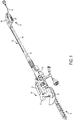
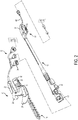
- the present invention is directed to a vegetation cutting tool having a powerhead 10 and an extensible pole assembly 12 as shown in Figs. 1 and 2 .
- Fig. 1 shows the pole assembly 12 secured to the powerhead 10 while Fig. 2 shows them separated.
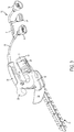
- the powerhead 10 is a hand-held tool with a blade assembly 14 extending out from a housing 16.
- the blade assembly 14 is shown as a hedgetrimmer blade made up of a pair of reciprocating blades that produce a shearing action to cut vegetation.
- the blade assembly shown in the figures is approximately 8 inches long, and is shorter than conventional hedgetrimmer blades which are typically 18 inches or longer. It should be understood however that other blade types and lengths may be used and fall within the scope of the present invention.
- the tool can have an interchangeable blade system that allows other blade assemblies, such as a shearing blade, to be swapped for the hedgetrimmer blade assembly as well.
- the housing 16 includes a motor chamber 18 that holds an electric motor 20 for powering the blade assembly 14.
- the housing 16 also includes a main handle 22, positioned above and parallel to the motor chamber 18, for a user to grip the tool.
- the main handle 22 includes a trigger 24 for actuating the motor 20.
- a support handle 26 Positioned adjacent the main handle 22 is a support handle 26 to provide additional control for the tool.
- a safety guard 28 Positioned just forward of the support handle 26 is a safety guard 28 for shielding the user's hand from the blade assembly 14.
- a power cord 30 for providing electrical power to the motor 20.
- An adapter cord 32 is tethered to the power cord 30 using a Velcro strap 31 or other similar attachment means.
- the power cord 30 has a three-pronged connector 34 which can be connected to the adapter cord 32 (or a corresponding connector 60 on the pole assembly 12, as discussed later).
- a first end of the adapter cord 32 has a connector 36 that corresponds to the connector 34 for connection therewith, and second end with a standard two-pronged electrical plug 38 that can be connected to an extension cord (not shown) or into a wall outlet for providing power.
- the power cord 30 is connected to the adapter cord 32, which is plugged into an electrical outlet.
- power to the motor 20 is controlled by trigger 24 on the main handle 22.
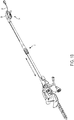
- FIG. 1B A first end of the pole assembly 12 has the connector 60 and a coupling member 40.
- a second end of the pole assembly includes a second handle 54 that allows the user to control the powerhead 10 when connected to the pole assembly 12.
- the second handle 54 includes a gripping portion 56 and a trigger 58.
- a standard two-pronged power cord 62 is located on the second handle 54 and plugs into a wall outlet or to an extension cord to deliver electricity to the power head 10.
- An electrical wire 61 located within the pole connects the power cord 62 to the connector 60.
- Fig. 4A shows a wire diagram of the powerhead 10 when connected to the adapter 32 and Fig. 4B shows a wire diagram of the powerhead 10 when connected to the pole assembly 12.
- the powerhead 10 is shown with a motor 20 electrically connected to the adapter 32 via the three pronged connection at connector 34 and 36.
- the three prongs are labelled L1, N, and L2.
- the trigger 24 of the powerhead 10 actuates a switch 24a to turn the motor on an off.
- Fig. 4A shows the switch 24a in the "off” position so that prongs N and L2 are connected to the motor.
- L2 is a "dead" wire (eg. not connected to the plug 38) and so the motor 20 is not powered.
- the switch 24a is turned to the "on” position, the prongs L1 and N are connected to the motor.
- L1 and N are “live” wires (eg. connected to plug 38) and so electrical power is transferred to the motor 20.
- the powerhead 10 is attached to the pole assembly 12 via connectors 34 and 60.
- the trigger 58 on the second handle 54 actuates a second switch 58a on the pole assembly.
- actuation of the motor 20 is transferred from the first trigger 24 on the powerhead 10 to the second trigger 58 on the pole assembly.
- the switch 24a on the powerhead 10 is in the "off” position so that N and L2 are the “live” wires.
- the second switch 58a is turned “on,” it completes the circuit and actuation of the motor is conducted through prongs N and L2.
- Prong L1 which was "live” wire in the powerhead only mode, is now a “dead wire.”
- a simple and cost effective means is provided to transfer control of the powerhead from the powerhead trigger 24 to pole assembly trigger 58. Furthermore, this design prevents accidential actuation of the tool through powerhead trigger 24 while the pole assembly is attached.
- the coupling member 40 includes a first section 42 and a second section 44 that are hinged together to open and close, so that in a closed position, it defines a cavity 45.
- a locking latch 46 is also hingedly connected to the first section 42, to lock the second section 44 in a closed position.
- the locking latch 46 includes a bar 48 that swings over a pair of catches 50 on the second section 44.
- the latch 46 includes a gripping portion 52 for a user to lock or unlock the latch 46.
- the motor chamber 18 of the power head 10 When joining the pole assembly 12 to the powerhead 10, the motor chamber 18 of the power head 10 is inserted into the cavity 45 of the coupling member 40. The second section 44 is then closed around the motor chamber 18 to engage the first section 42, and securely hold the power head 10. The bar 48 of the latch 46 is then swung over the catches 50, and the gripping portion 52 can be rotated to lie against the first section 42, which is the locked position. The locked position can be seen in Figs. 6A and 6B (power head not shown).
- the motor chamber 18 of the housing By isolating the motor chamber 18 of the housing, a easily accessible and rigid section of the powerhead is provided for attaching the coupling member 40 of the pole assembly. Also, by locating the power cord 30 on the main handle 22, away from the motor chamber 18, the power cord does not interfere with the coupling of the pole assembly 12. Additionally, the motor chamber 18 has a slightly oval shape so that coupling member 40 rotatably aligns the powerhead 10 with the pole assembly 12. It should be understood that the motor chamber can have any shape, although it is preferred that it be one that automatically aligns the powerhead relative to the pole assembly.
- the coupling member 40 can be pivotably attached to the pole assembly 12.
- the coupling member 40 includes a spindle 41 extending from its end, and secure within a bracket 66 on the pole assembly 12.
- the bracket 66 has two ears 70 that support the spindle 41 on opposite sides.
- An pin (not shown) goes through the ears 70 and spindle 41 allowing the coupling member 40 to rotate.
- a lever 72 is secured to one end of the pin.
- the lever 72 includes a handle 74 and a cammed end portion 76 that urges the ears 70 toward one another to pivotally lock the coupling member 40 in position.
- Fig. 6A shows the locked position
- Fig. 7 shows an unlocked position.
Landscapes
- Life Sciences & Earth Sciences (AREA)
- Biodiversity & Conservation Biology (AREA)
- Ecology (AREA)
- Forests & Forestry (AREA)
- Environmental Sciences (AREA)
- Harvester Elements (AREA)
Abstract
Description
- The invention relates generally to a multi-purpose electrically powered hand-held garden tool for cutting vegetation that can be used alone or attached to a pole assembly for extending the reach of the tool.
- Most current powered garden tools are hand-held tools used to cut vegetation near the user. However, oftentimes tall bushes or trees are present and a user needs to be able to reach distant growth. In those cases, users often have separate tools with integrated poles to allow the user to reach the vegetation. However, for many garden tools, such as a hedgetrimmer, the tool's weight and size make controlling and using such a tool difficult. For example, most hedgetrimmers have blade lengths of 18 inches or longer. This issue is exacerbated with gasoline powered tools where the weight of the engine and gasoline contribute significantly to the weight and size of the tool.
- With respect to electrical tools, they are an improvement over gasoline powered tools as electric motors are typically much lighter than gas engines. However, electric tools, which can be either cordless (eg. battery powered) or corded, have their own disadvantages. Battery powered electric tools have the added weight of a battery, and corded electric tools have to contend with cords which can become tangled and cumbersome to pull around.
- Furthermore, all of the above types of tools have the challenge of how to acutate the tool when attached to a pole assembly. When used alone, the tool is controlled by a trigger or other actuation means on the tool itself, however, when attached to a pole the tool is separated from the user, and the user needs a way of actuating the tool from the pole. Therefore, the pole itself must have a separate trigger or actuation means.
- Therefore, it would be desirable to have a small garden tool, such as a hedgetrimmer, that is lighter weight and easy to manoeuvre for use individually and when attached to a pole. Furthermore, it would be desirable to have a simple and cost effective method of attaching and actuating a tool from a pole.
- In light of the above need, a brief summary of various exemplary embodiments is presented. Some simplifications and omissions may be made in the following summary, which is intended to highlight and introduce some aspects of the various exemplary embodiments, but not to limit the scope of the invention. Detailed descriptions of a preferred exemplary embodiment adequate to allow those of ordinary skill in the art to make and use the inventive concepts will follow in later sections.
- The powered garden tool includes a powerhead having a housing with a main handle and a motor chamber, and a pole assembly adapted to be releasably connected to the powerhead housing to extend the reach of the blade assembly. The main handle includes a trigger to allow actuation of the tool when the pole assembly is not attached. When the pole assembly is attached, the powerhead is electrically connected to the pole assembly, which includes a second trigger to actuate the tool.
- The present invention further includes powerhead housing where the main handle and motor chamber are separated, and extend rearwardly from a front portion of the housing parallel to one another.
- The pole assembly further includes a coupling member for securing it to the powerhead. The coupling member is secured to the motor chamber of the powerhead, with the components being keyed to one another so that the powerhead is properly aligned with the pole assembly when attached.
- Further features and advantages of the present invention will be better understood by reference to the following description, which is given by way of example and in association with the accompanying drawings, in which:
-
Fig. 1 is a perspective view of a vegetation cutting tool attached to a pole assembly according to an embodiment of the invention; -
Fig. 1B is a perspective view of the vegetation cutting tool ofFig. 1 with the pole assembly in an extended position; -
Fig. 2 is a perspective view ofFig. 1 with the powerhead separated from the pole assembly; -
Fig. 3 is a perspective view of the powerhead ofFig. 1 ; -
Fig. 4A is a wire diagram of the powerhead; -
Fig. 4B is a wire diagram of the powerhead when attached to a pole assembly; -
Fig. 5A is side view of a coupling member for the pole assembly in an open position; -
Fig. 5B is a top perspective view of the coupling member ofFig. 5A ; -
Fig. 6A is a side view of the coupling member ofFig. 5A in a closed position; -
Fig. 6B is a top view of the coupling member ofFig. 5A in a closed position; and -
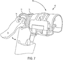
Fig. 7 shows the coupling member in a pivoted position. - The present invention is directed to a vegetation cutting tool having a
powerhead 10 and anextensible pole assembly 12 as shown inFigs. 1 and2 .Fig. 1 shows thepole assembly 12 secured to thepowerhead 10 whileFig. 2 shows them separated. - The
powerhead 10, as best shown inFig. 3 , is a hand-held tool with ablade assembly 14 extending out from ahousing 16. Theblade assembly 14 is shown as a hedgetrimmer blade made up of a pair of reciprocating blades that produce a shearing action to cut vegetation. The blade assembly shown in the figures is approximately 8 inches long, and is shorter than conventional hedgetrimmer blades which are typically 18 inches or longer. It should be understood however that other blade types and lengths may be used and fall within the scope of the present invention. Furthermore, the tool can have an interchangeable blade system that allows other blade assemblies, such as a shearing blade, to be swapped for the hedgetrimmer blade assembly as well. - The
housing 16 includes amotor chamber 18 that holds anelectric motor 20 for powering theblade assembly 14. Thehousing 16 also includes amain handle 22, positioned above and parallel to themotor chamber 18, for a user to grip the tool. Themain handle 22 includes atrigger 24 for actuating themotor 20. Positioned adjacent themain handle 22 is asupport handle 26 to provide additional control for the tool. Positioned just forward of thesupport handle 26 is asafety guard 28 for shielding the user's hand from theblade assembly 14. - Referring now to
Figs. 2 and3 , extending from the rear of themain handle 22 is apower cord 30 for providing electrical power to themotor 20. Anadapter cord 32 is tethered to thepower cord 30 using a Velcrostrap 31 or other similar attachment means. Thepower cord 30 has a three-prongedconnector 34 which can be connected to the adapter cord 32 (or acorresponding connector 60 on thepole assembly 12, as discussed later). - A first end of the
adapter cord 32 has aconnector 36 that corresponds to theconnector 34 for connection therewith, and second end with a standard two-prongedelectrical plug 38 that can be connected to an extension cord (not shown) or into a wall outlet for providing power. In this way, when the cutting tool is used alone as a hand-held unit, e.g. without thepole assembly 12, thepower cord 30 is connected to theadapter cord 32, which is plugged into an electrical outlet. In this configuration, power to themotor 20 is controlled bytrigger 24 on themain handle 22. - Referring now to
Figs. 1 and2 , thepole assembly 12 is shown attached and detached from thepowerhead 10, respectively. Thepole assembly 12 is also telescopic and can be extended, as shown inFig. 1B . A first end of thepole assembly 12 has theconnector 60 and acoupling member 40. A second end of the pole assembly includes asecond handle 54 that allows the user to control thepowerhead 10 when connected to thepole assembly 12. Thesecond handle 54 includes a grippingportion 56 and atrigger 58. A standard two-pronged power cord 62 is located on thesecond handle 54 and plugs into a wall outlet or to an extension cord to deliver electricity to thepower head 10. Anelectrical wire 61 located within the pole connects thepower cord 62 to theconnector 60. -
Fig. 4A shows a wire diagram of thepowerhead 10 when connected to theadapter 32 andFig. 4B shows a wire diagram of thepowerhead 10 when connected to thepole assembly 12. Referring toFig. 4A , thepowerhead 10 is shown with amotor 20 electrically connected to theadapter 32 via the three pronged connection atconnector trigger 24 of thepowerhead 10 actuates aswitch 24a to turn the motor on an off.Fig. 4A shows theswitch 24a in the "off" position so that prongs N and L2 are connected to the motor. L2 is a "dead" wire (eg. not connected to the plug 38) and so themotor 20 is not powered. When theswitch 24a is turned to the "on" position, the prongs L1 and N are connected to the motor. L1 and N are "live" wires (eg. connected to plug 38) and so electrical power is transferred to themotor 20. - Now referring to
Fig. 4B , thepowerhead 10 is attached to thepole assembly 12 viaconnectors trigger 58 on thesecond handle 54 actuates asecond switch 58a on the pole assembly. Here actuation of themotor 20 is transferred from thefirst trigger 24 on thepowerhead 10 to thesecond trigger 58 on the pole assembly. Theswitch 24a on thepowerhead 10 is in the "off" position so that N and L2 are the "live" wires. When thesecond switch 58a is turned "on," it completes the circuit and actuation of the motor is conducted through prongs N and L2. Prong L1, which was "live" wire in the powerhead only mode, is now a "dead wire." Using this design, a simple and cost effective means is provided to transfer control of the powerhead from thepowerhead trigger 24 topole assembly trigger 58. Furthermore, this design prevents accidential actuation of the tool throughpowerhead trigger 24 while the pole assembly is attached. - Now referring to
Figs. 5A and5B , thecoupling member 40 is shown in more detail. The figures show an over-center type of clamp, but it should be understood that any coupling mechanism can be used and fall within the scope of the invention. Thecoupling member 40 includes afirst section 42 and asecond section 44 that are hinged together to open and close, so that in a closed position, it defines acavity 45. A lockinglatch 46 is also hingedly connected to thefirst section 42, to lock thesecond section 44 in a closed position. The lockinglatch 46 includes abar 48 that swings over a pair ofcatches 50 on thesecond section 44. Thelatch 46 includes a grippingportion 52 for a user to lock or unlock thelatch 46. - When joining the
pole assembly 12 to thepowerhead 10, themotor chamber 18 of thepower head 10 is inserted into thecavity 45 of thecoupling member 40. Thesecond section 44 is then closed around themotor chamber 18 to engage thefirst section 42, and securely hold thepower head 10. Thebar 48 of thelatch 46 is then swung over thecatches 50, and the grippingportion 52 can be rotated to lie against thefirst section 42, which is the locked position. The locked position can be seen inFigs. 6A and6B (power head not shown). - By isolating the
motor chamber 18 of the housing, a easily accessible and rigid section of the powerhead is provided for attaching thecoupling member 40 of the pole assembly. Also, by locating thepower cord 30 on themain handle 22, away from themotor chamber 18, the power cord does not interfere with the coupling of thepole assembly 12. Additionally, themotor chamber 18 has a slightly oval shape so that couplingmember 40 rotatably aligns thepowerhead 10 with thepole assembly 12. It should be understood that the motor chamber can have any shape, although it is preferred that it be one that automatically aligns the powerhead relative to the pole assembly. - Now referring to
Figs 6A and7 , a further embodiment of the invention will now be described. The figures show that thecoupling member 40 can be pivotably attached to thepole assembly 12. Thecoupling member 40 includes aspindle 41 extending from its end, and secure within abracket 66 on thepole assembly 12. Thebracket 66 has twoears 70 that support thespindle 41 on opposite sides. An pin (not shown) goes through theears 70 andspindle 41 allowing thecoupling member 40 to rotate. Alever 72 is secured to one end of the pin. Thelever 72 includes ahandle 74 and acammed end portion 76 that urges theears 70 toward one another to pivotally lock thecoupling member 40 in position.Fig. 6A shows the locked position andFig. 7 shows an unlocked position. - The foregoing description of the embodiments has been provided for purposes of illustration and description. It is not intended to be exhaustive or to limit the disclosure. Individual elements or features of a particular embodiment are generally not limited to that particular embodiment, but, where applicable, are interchangeable and can be used in a selected embodiment, even if not specifically shown or described. The same may also be varied in many ways. Such variations are not to be regarded as a departure from the disclosure, and all such modifications are intended to be included within the scope of the disclosure
Claims (15)
- A powered garden tool comprising:a powerhead having a housing, the housing having an motor chamber for holding an electric motor, a main handle capable of being gripped by a user, the main handle having a first trigger to turn the motor on or off;a blade assembly driveably connected to the motor and extending out from a front portion of the housing;a pole assembly having a coupling member capable of removably connecting to the motor chamber of the powerhead for use in a poled configuration.
- The powered garden tool of claim 1, further comprising an adapter that connects to a first power cord on the powerhead for use in a hand-held configuration, the adapter capable of connecting to a power outlet; and
wherein the first power cord is electrically connected to a second power cord on the pole assembly when used in the poled configuration, the second power cord capable of connecting to the power outlet. - The powered garden tool of claim 1 or 2, wherein the pole assembly includes a second trigger, and when the tool is in the poled configuration, the second trigger is used to actuate power to the motor.
- The powered garden tool of claim 2, wherein the adapter is tethered to the first power cord.
- The powered garden tool of any of the preceding claims, wherein the pole assembly includes a coupling member for securing it to the motor chamber, the motor chamber and coupling member being correspondingly shaped so that the position of the motor chamber is aligned within the coupling member.
- The powered garden tool of any of the preceding claims, wherein the main handle and the motor chamber are parallel to one another, and extend rearwardly from a front portion of the housing.
- The powered garden tool of any of the preceding claims, wherein the powerhead is pivotable relative to the pole assembly.
- A powered garden tool comprising:a powerhead having a housing with a first handle and a motor chamber, an electric motor located in said motor chamber, and a power cord to supply power to the motor attached to said housing, the first handle having a first trigger to actuate the motor;a blade assembly extending out from a front portion of the housing and operatively connected to the motor;a pole assembly adapted to be connected to the powerhead housing to extend the reach of the blade assembly, the pole assembly having an electrical connector on a first end, and second handle and a second power cord on a second end, the second handle having a second trigger, the electrical connector being electrically connected to the second power cord; andwherein when the pole assembly is not attached to the powerhead, actuation of the motor is controlled by the first trigger, and when the pole assembly is attached to the powerhead and the first power cord is connected to the electrical connector of the pole assembly, actuation of the motor is controlled by the second trigger.
- The powered garden tool of claim 8, further comprising an adapter cord capable of connecting the first power cord to an electrical outlet.
- The powered garden tool of claim 9, wherein the adapter is tethered to the first power cord.
- The powered garden tool of any of claims 8 to 10, wherein the first handle and motor chamber extend rearwardly from a front portion of the housing, and are parallel to one another.
- The powered garden tool of any of claims 8 to 11, wherein the pole assembly is attached to the motor chamber.
- The powered garden tool of any of claims 8 to 12, wherein the powerhead is pivotable relative to the pole assembly assembly.
- A method of attaching a pole assembly to a garden tool powerhead, comprising the steps of:providing a powerhead having a housing with a first handle and a motor chamber, an electric motor located in said motor chamber, and a power cord to supply power to the motor attached to said housing, the first handle having a first trigger to actuate the motor, a blade assembly extending out from a front portion of the housing and operatively connected to the motor;attaching a pole assembly to the powerhead housing, the pole assembly having an electrical connector on a first end, and second handle and a second power cord on a second end, the second handle having a second trigger, the electrical connector being electrically connected to the second power cord, and wherein when the pole assembly is attached to the powerhead, actuation of the motor is controlled by the second trigger.
- The method of attaching a pole assembly to a garden tool powerhead of claim 14, wherein the first handle and motor chamber extend rearwardly from a front portion of the housing, and the pole assembly is attached to the motor housing.
Applications Claiming Priority (1)
| Application Number | Priority Date | Filing Date | Title |
|---|---|---|---|
| US15/059,740 US10420287B2 (en) | 2016-03-03 | 2016-03-03 | Pole assembly for vegetation cutting tool |
Publications (2)
| Publication Number | Publication Date |
|---|---|
| EP3213627A1 true EP3213627A1 (en) | 2017-09-06 |
| EP3213627B1 EP3213627B1 (en) | 2021-11-03 |
Family
ID=58057016
Family Applications (1)
| Application Number | Title | Priority Date | Filing Date |
|---|---|---|---|
| EP17156620.1A Active EP3213627B1 (en) | 2016-03-03 | 2017-02-17 | Pole assembly for vegetation cutting tool |
Country Status (3)
| Country | Link |
|---|---|
| US (2) | US10420287B2 (en) |
| EP (1) | EP3213627B1 (en) |
| CN (1) | CN207104838U (en) |
Cited By (2)
| Publication number | Priority date | Publication date | Assignee | Title |
|---|---|---|---|---|
| WO2020035281A1 (en) | 2018-08-17 | 2020-02-20 | Crochat Philippe | Pruning device comprising at least one gripping handle, a clipping/cutting-back tool and motorised aerodynamic levitation means |
| WO2020035291A1 (en) | 2018-08-17 | 2020-02-20 | Crochat Philippe | Assembly comprising a gripping handle for a working tool and motorised aerodynamic levitation means |
Families Citing this family (11)
| Publication number | Priority date | Publication date | Assignee | Title |
|---|---|---|---|---|
| US9877435B2 (en) * | 2015-09-15 | 2018-01-30 | Chervon (Hk) Limited | Hedge trimmer |
| CN114502332B (en) * | 2019-10-02 | 2024-11-29 | 胡斯华纳有限公司 | Battery adapter assembly and hand-held power tool |
| WO2021120859A1 (en) * | 2019-12-19 | 2021-06-24 | Techtronic Cordless Gp | Electric cultivator |
| US11697199B2 (en) * | 2021-02-24 | 2023-07-11 | Towa Industries, Incorporated | Power landscaping tool ensemble for using multiple tool heads |
| DE102021132353A1 (en) * | 2021-12-08 | 2023-06-15 | Mtd Products Inc. | Handling device and processing device, in particular gardening and/or household appliance, with such a handling device |
| EP4296007A1 (en) * | 2022-05-09 | 2023-12-27 | Husqvarna AB | Handheld power tool, pole extension unit and power tool assembly |
| CN117356283A (en) * | 2022-06-30 | 2024-01-09 | 南京泉峰科技有限公司 | Pruning machine |
| US12023824B1 (en) * | 2023-05-26 | 2024-07-02 | Jayantha Sarath Mallikarachchi | Triple saw |
| US20240397878A1 (en) * | 2023-06-04 | 2024-12-05 | Greenworks (Jiangsu) Co., Ltd. | Hedge Trimmer |
| USD1005805S1 (en) * | 2023-07-06 | 2023-11-28 | Jinyun Mailin Tools Co., Ltd | Garden tool |
| USD1005068S1 (en) * | 2023-07-14 | 2023-11-21 | Jinhua Xiaoyi Tools Co., Ltd | High branch pole |
Citations (7)
| Publication number | Priority date | Publication date | Assignee | Title |
|---|---|---|---|---|
| US4207675A (en) * | 1978-05-15 | 1980-06-17 | Clarence Burchell | Adjustable utility extension handle for electrically powered handtool |
| US4515423A (en) * | 1983-04-04 | 1985-05-07 | Moore Jerry R | Extension device for electrically powered tools |
| US5787590A (en) * | 1994-01-10 | 1998-08-04 | D'alessandro, Sr.; Thomas C. | Extension and support for electric clippers |
| US5884403A (en) * | 1997-01-08 | 1999-03-23 | Rogers; Ronald E. | Powered tree limb trimming device |
| US20050086813A1 (en) * | 2003-10-23 | 2005-04-28 | Champlin David E. | Electric pole saw |
| US20060005673A1 (en) * | 2004-07-12 | 2006-01-12 | Homelite Technologies Ltd. | Extendable chain saw system |
| US20080196256A1 (en) * | 2007-02-06 | 2008-08-21 | Jason Gieske | Split power tool |
Family Cites Families (15)
| Publication number | Priority date | Publication date | Assignee | Title |
|---|---|---|---|---|
| US2748476A (en) * | 1954-10-29 | 1956-06-05 | Woodrow J Cooper | Portable device for trimming trees |
| US3579827A (en) * | 1966-08-01 | 1971-05-25 | Sunbeam Corp | Hedge trimmer |
| US3731380A (en) * | 1971-12-20 | 1973-05-08 | R Mathiesen | Chain-saw extension pole |
| US3805385A (en) * | 1972-10-11 | 1974-04-23 | Sunbeam Corp | Housing for a portable grass shear |
| US3973179A (en) | 1974-08-23 | 1976-08-03 | The Black And Decker Manufacturing Company | Modular cordless tools |
| US4050003A (en) | 1974-08-23 | 1977-09-20 | The Black And Decker Manufacturing Company | Modular cordless tools |
| US4330938A (en) * | 1981-05-11 | 1982-05-25 | Martin Raymond G | Carpet stripping machine |
| US5070576A (en) * | 1990-11-21 | 1991-12-10 | Banta Jerry W | Hedge trimmer extension handle apparatus |
| US5802724A (en) | 1994-09-09 | 1998-09-08 | Ryobi North America | Coupling for split-boom power tool |
| AU3546395A (en) | 1994-09-09 | 1996-03-27 | Ryobi North America, Inc. | Attachment system for battery powered tool |
| US6181032B1 (en) | 1999-07-14 | 2001-01-30 | Black & Decker Inc. | Releasably connecting power packs to electrical appliances |
| US6474747B2 (en) | 2000-11-30 | 2002-11-05 | Homelite Technologies Limited | Split boom coupling structure |
| US6349712B1 (en) * | 2001-01-19 | 2002-02-26 | David Halstead | Saw extension |
| US7484300B2 (en) | 2004-09-09 | 2009-02-03 | Black & Decker Inc. | Extensible pole saw having separable sections |
| US7989718B1 (en) * | 2009-05-08 | 2011-08-02 | Weber Eugene A | Power control engagement device for a power tool |
-
2016
- 2016-03-03 US US15/059,740 patent/US10420287B2/en active Active
-
2017
- 2017-02-17 EP EP17156620.1A patent/EP3213627B1/en active Active
- 2017-03-03 CN CN201720423050.XU patent/CN207104838U/en not_active Expired - Fee Related
-
2019
- 2019-08-28 US US16/553,575 patent/US20210068350A1/en not_active Abandoned
Patent Citations (7)
| Publication number | Priority date | Publication date | Assignee | Title |
|---|---|---|---|---|
| US4207675A (en) * | 1978-05-15 | 1980-06-17 | Clarence Burchell | Adjustable utility extension handle for electrically powered handtool |
| US4515423A (en) * | 1983-04-04 | 1985-05-07 | Moore Jerry R | Extension device for electrically powered tools |
| US5787590A (en) * | 1994-01-10 | 1998-08-04 | D'alessandro, Sr.; Thomas C. | Extension and support for electric clippers |
| US5884403A (en) * | 1997-01-08 | 1999-03-23 | Rogers; Ronald E. | Powered tree limb trimming device |
| US20050086813A1 (en) * | 2003-10-23 | 2005-04-28 | Champlin David E. | Electric pole saw |
| US20060005673A1 (en) * | 2004-07-12 | 2006-01-12 | Homelite Technologies Ltd. | Extendable chain saw system |
| US20080196256A1 (en) * | 2007-02-06 | 2008-08-21 | Jason Gieske | Split power tool |
Cited By (4)
| Publication number | Priority date | Publication date | Assignee | Title |
|---|---|---|---|---|
| WO2020035281A1 (en) | 2018-08-17 | 2020-02-20 | Crochat Philippe | Pruning device comprising at least one gripping handle, a clipping/cutting-back tool and motorised aerodynamic levitation means |
| WO2020035291A1 (en) | 2018-08-17 | 2020-02-20 | Crochat Philippe | Assembly comprising a gripping handle for a working tool and motorised aerodynamic levitation means |
| FR3085012A1 (en) * | 2018-08-17 | 2020-02-21 | Philippe CROCHAT | ASSEMBLY COMPRISING A GRIPPING HANDLE FOR A WORKING TOOL AND MOTORIZED AERODYNAMIC LEVITATION MEANS |
| FR3084990A1 (en) * | 2018-08-17 | 2020-02-21 | Philippe CROCHAT | PRUNING DEVICE COMPRISING AT LEAST ONE GRIPPING HANDLE, A PRUNING / TRIMMING TOOL AND MOTORIZED AERODYNAMIC LEVITATION MEANS |
Also Published As
| Publication number | Publication date |
|---|---|
| CN207104838U (en) | 2018-03-16 |
| EP3213627B1 (en) | 2021-11-03 |
| US10420287B2 (en) | 2019-09-24 |
| US20210068350A1 (en) | 2021-03-11 |
| US20170251608A1 (en) | 2017-09-07 |
Similar Documents
| Publication | Publication Date | Title |
|---|---|---|
| EP3213627B1 (en) | Pole assembly for vegetation cutting tool | |
| US8136254B2 (en) | Split power tool with extension | |
| US9591809B2 (en) | Split power tool | |
| AU2020233621B2 (en) | Split power tool | |
| US11116122B2 (en) | Handheld lawn maintenance tool | |
| US20140208598A1 (en) | Vegetation cutter | |
| EP3815504B1 (en) | Poled cutting device with a hinge allowing the pole to be folded | |
| US20080184568A1 (en) | Split Power Tool | |
| TWI471087B (en) | Power tool | |
| EP2277237A2 (en) | Power connection system | |
| US6484484B1 (en) | Lawn mower for providing power to a garden implement | |
| JP6253088B2 (en) | Back working machine | |
| CN108472800A (en) | Power tool attachment, power tool and method of operating a power tool | |
| JP2014194950A (en) | Battery device for power tool | |
| CN104097189B (en) | Handleset and there is the electric tool of this Handleset | |
| US20120073145A1 (en) | Weed trimmer with electrical starting mechanism | |
| GB2633811A (en) | Remote battery switch adapter apparatus and method of operating a battery-powered lawn trimmer |
Legal Events
| Date | Code | Title | Description |
|---|---|---|---|
| PUAI | Public reference made under article 153(3) epc to a published international application that has entered the european phase |
Free format text: ORIGINAL CODE: 0009012 |
|
| STAA | Information on the status of an ep patent application or granted ep patent |
Free format text: STATUS: THE APPLICATION HAS BEEN PUBLISHED |
|
| AK | Designated contracting states |
Kind code of ref document: A1 Designated state(s): AL AT BE BG CH CY CZ DE DK EE ES FI FR GB GR HR HU IE IS IT LI LT LU LV MC MK MT NL NO PL PT RO RS SE SI SK SM TR |
|
| AX | Request for extension of the european patent |
Extension state: BA ME |
|
| STAA | Information on the status of an ep patent application or granted ep patent |
Free format text: STATUS: REQUEST FOR EXAMINATION WAS MADE |
|
| 17P | Request for examination filed |
Effective date: 20180124 |
|
| RBV | Designated contracting states (corrected) |
Designated state(s): AL AT BE BG CH CY CZ DE DK EE ES FI FR GB GR HR HU IE IS IT LI LT LU LV MC MK MT NL NO PL PT RO RS SE SI SK SM TR |
|
| GRAP | Despatch of communication of intention to grant a patent |
Free format text: ORIGINAL CODE: EPIDOSNIGR1 |
|
| STAA | Information on the status of an ep patent application or granted ep patent |
Free format text: STATUS: GRANT OF PATENT IS INTENDED |
|
| INTG | Intention to grant announced |
Effective date: 20210616 |
|
| GRAS | Grant fee paid |
Free format text: ORIGINAL CODE: EPIDOSNIGR3 |
|
| GRAA | (expected) grant |
Free format text: ORIGINAL CODE: 0009210 |
|
| STAA | Information on the status of an ep patent application or granted ep patent |
Free format text: STATUS: THE PATENT HAS BEEN GRANTED |
|
| AK | Designated contracting states |
Kind code of ref document: B1 Designated state(s): AL AT BE BG CH CY CZ DE DK EE ES FI FR GB GR HR HU IE IS IT LI LT LU LV MC MK MT NL NO PL PT RO RS SE SI SK SM TR |
|
| REG | Reference to a national code |
Ref country code: GB Ref legal event code: FG4D |
|
| REG | Reference to a national code |
Ref country code: AT Ref legal event code: REF Ref document number: 1443152 Country of ref document: AT Kind code of ref document: T Effective date: 20211115 Ref country code: CH Ref legal event code: EP |
|
| REG | Reference to a national code |
Ref country code: DE Ref legal event code: R096 Ref document number: 602017048571 Country of ref document: DE |
|
| REG | Reference to a national code |
Ref country code: IE Ref legal event code: FG4D |
|
| REG | Reference to a national code |
Ref country code: LT Ref legal event code: MG9D |
|
| REG | Reference to a national code |
Ref country code: NL Ref legal event code: MP Effective date: 20211103 |
|
| REG | Reference to a national code |
Ref country code: AT Ref legal event code: MK05 Ref document number: 1443152 Country of ref document: AT Kind code of ref document: T Effective date: 20211103 |
|
| PG25 | Lapsed in a contracting state [announced via postgrant information from national office to epo] |
Ref country code: RS Free format text: LAPSE BECAUSE OF FAILURE TO SUBMIT A TRANSLATION OF THE DESCRIPTION OR TO PAY THE FEE WITHIN THE PRESCRIBED TIME-LIMIT Effective date: 20211103 Ref country code: LT Free format text: LAPSE BECAUSE OF FAILURE TO SUBMIT A TRANSLATION OF THE DESCRIPTION OR TO PAY THE FEE WITHIN THE PRESCRIBED TIME-LIMIT Effective date: 20211103 Ref country code: FI Free format text: LAPSE BECAUSE OF FAILURE TO SUBMIT A TRANSLATION OF THE DESCRIPTION OR TO PAY THE FEE WITHIN THE PRESCRIBED TIME-LIMIT Effective date: 20211103 Ref country code: BG Free format text: LAPSE BECAUSE OF FAILURE TO SUBMIT A TRANSLATION OF THE DESCRIPTION OR TO PAY THE FEE WITHIN THE PRESCRIBED TIME-LIMIT Effective date: 20220203 Ref country code: AT Free format text: LAPSE BECAUSE OF FAILURE TO SUBMIT A TRANSLATION OF THE DESCRIPTION OR TO PAY THE FEE WITHIN THE PRESCRIBED TIME-LIMIT Effective date: 20211103 |
|
| PG25 | Lapsed in a contracting state [announced via postgrant information from national office to epo] |
Ref country code: IS Free format text: LAPSE BECAUSE OF FAILURE TO SUBMIT A TRANSLATION OF THE DESCRIPTION OR TO PAY THE FEE WITHIN THE PRESCRIBED TIME-LIMIT Effective date: 20220303 Ref country code: SE Free format text: LAPSE BECAUSE OF FAILURE TO SUBMIT A TRANSLATION OF THE DESCRIPTION OR TO PAY THE FEE WITHIN THE PRESCRIBED TIME-LIMIT Effective date: 20211103 Ref country code: PT Free format text: LAPSE BECAUSE OF FAILURE TO SUBMIT A TRANSLATION OF THE DESCRIPTION OR TO PAY THE FEE WITHIN THE PRESCRIBED TIME-LIMIT Effective date: 20220303 Ref country code: PL Free format text: LAPSE BECAUSE OF FAILURE TO SUBMIT A TRANSLATION OF THE DESCRIPTION OR TO PAY THE FEE WITHIN THE PRESCRIBED TIME-LIMIT Effective date: 20211103 Ref country code: NO Free format text: LAPSE BECAUSE OF FAILURE TO SUBMIT A TRANSLATION OF THE DESCRIPTION OR TO PAY THE FEE WITHIN THE PRESCRIBED TIME-LIMIT Effective date: 20220203 Ref country code: NL Free format text: LAPSE BECAUSE OF FAILURE TO SUBMIT A TRANSLATION OF THE DESCRIPTION OR TO PAY THE FEE WITHIN THE PRESCRIBED TIME-LIMIT Effective date: 20211103 Ref country code: LV Free format text: LAPSE BECAUSE OF FAILURE TO SUBMIT A TRANSLATION OF THE DESCRIPTION OR TO PAY THE FEE WITHIN THE PRESCRIBED TIME-LIMIT Effective date: 20211103 Ref country code: HR Free format text: LAPSE BECAUSE OF FAILURE TO SUBMIT A TRANSLATION OF THE DESCRIPTION OR TO PAY THE FEE WITHIN THE PRESCRIBED TIME-LIMIT Effective date: 20211103 Ref country code: GR Free format text: LAPSE BECAUSE OF FAILURE TO SUBMIT A TRANSLATION OF THE DESCRIPTION OR TO PAY THE FEE WITHIN THE PRESCRIBED TIME-LIMIT Effective date: 20220204 Ref country code: ES Free format text: LAPSE BECAUSE OF FAILURE TO SUBMIT A TRANSLATION OF THE DESCRIPTION OR TO PAY THE FEE WITHIN THE PRESCRIBED TIME-LIMIT Effective date: 20211103 |
|
| PG25 | Lapsed in a contracting state [announced via postgrant information from national office to epo] |
Ref country code: SM Free format text: LAPSE BECAUSE OF FAILURE TO SUBMIT A TRANSLATION OF THE DESCRIPTION OR TO PAY THE FEE WITHIN THE PRESCRIBED TIME-LIMIT Effective date: 20211103 Ref country code: SK Free format text: LAPSE BECAUSE OF FAILURE TO SUBMIT A TRANSLATION OF THE DESCRIPTION OR TO PAY THE FEE WITHIN THE PRESCRIBED TIME-LIMIT Effective date: 20211103 Ref country code: RO Free format text: LAPSE BECAUSE OF FAILURE TO SUBMIT A TRANSLATION OF THE DESCRIPTION OR TO PAY THE FEE WITHIN THE PRESCRIBED TIME-LIMIT Effective date: 20211103 Ref country code: EE Free format text: LAPSE BECAUSE OF FAILURE TO SUBMIT A TRANSLATION OF THE DESCRIPTION OR TO PAY THE FEE WITHIN THE PRESCRIBED TIME-LIMIT Effective date: 20211103 Ref country code: DK Free format text: LAPSE BECAUSE OF FAILURE TO SUBMIT A TRANSLATION OF THE DESCRIPTION OR TO PAY THE FEE WITHIN THE PRESCRIBED TIME-LIMIT Effective date: 20211103 Ref country code: CZ Free format text: LAPSE BECAUSE OF FAILURE TO SUBMIT A TRANSLATION OF THE DESCRIPTION OR TO PAY THE FEE WITHIN THE PRESCRIBED TIME-LIMIT Effective date: 20211103 |
|
| REG | Reference to a national code |
Ref country code: DE Ref legal event code: R097 Ref document number: 602017048571 Country of ref document: DE |
|
| PLBE | No opposition filed within time limit |
Free format text: ORIGINAL CODE: 0009261 |
|
| STAA | Information on the status of an ep patent application or granted ep patent |
Free format text: STATUS: NO OPPOSITION FILED WITHIN TIME LIMIT |
|
| PG25 | Lapsed in a contracting state [announced via postgrant information from national office to epo] |
Ref country code: MC Free format text: LAPSE BECAUSE OF FAILURE TO SUBMIT A TRANSLATION OF THE DESCRIPTION OR TO PAY THE FEE WITHIN THE PRESCRIBED TIME-LIMIT Effective date: 20211103 |
|
| 26N | No opposition filed |
Effective date: 20220804 |
|
| REG | Reference to a national code |
Ref country code: CH Ref legal event code: PL |
|
| REG | Reference to a national code |
Ref country code: BE Ref legal event code: MM Effective date: 20220228 |
|
| PG25 | Lapsed in a contracting state [announced via postgrant information from national office to epo] |
Ref country code: LU Free format text: LAPSE BECAUSE OF NON-PAYMENT OF DUE FEES Effective date: 20220217 Ref country code: AL Free format text: LAPSE BECAUSE OF FAILURE TO SUBMIT A TRANSLATION OF THE DESCRIPTION OR TO PAY THE FEE WITHIN THE PRESCRIBED TIME-LIMIT Effective date: 20211103 |
|
| PG25 | Lapsed in a contracting state [announced via postgrant information from national office to epo] |
Ref country code: SI Free format text: LAPSE BECAUSE OF FAILURE TO SUBMIT A TRANSLATION OF THE DESCRIPTION OR TO PAY THE FEE WITHIN THE PRESCRIBED TIME-LIMIT Effective date: 20211103 |
|
| PG25 | Lapsed in a contracting state [announced via postgrant information from national office to epo] |
Ref country code: FR Free format text: LAPSE BECAUSE OF NON-PAYMENT OF DUE FEES Effective date: 20220228 |
|
| PG25 | Lapsed in a contracting state [announced via postgrant information from national office to epo] |
Ref country code: LI Free format text: LAPSE BECAUSE OF NON-PAYMENT OF DUE FEES Effective date: 20220228 Ref country code: IE Free format text: LAPSE BECAUSE OF NON-PAYMENT OF DUE FEES Effective date: 20220217 Ref country code: CH Free format text: LAPSE BECAUSE OF NON-PAYMENT OF DUE FEES Effective date: 20220228 |
|
| PG25 | Lapsed in a contracting state [announced via postgrant information from national office to epo] |
Ref country code: BE Free format text: LAPSE BECAUSE OF NON-PAYMENT OF DUE FEES Effective date: 20220228 |
|
| PG25 | Lapsed in a contracting state [announced via postgrant information from national office to epo] |
Ref country code: IT Free format text: LAPSE BECAUSE OF FAILURE TO SUBMIT A TRANSLATION OF THE DESCRIPTION OR TO PAY THE FEE WITHIN THE PRESCRIBED TIME-LIMIT Effective date: 20211103 |
|
| PG25 | Lapsed in a contracting state [announced via postgrant information from national office to epo] |
Ref country code: HU Free format text: LAPSE BECAUSE OF FAILURE TO SUBMIT A TRANSLATION OF THE DESCRIPTION OR TO PAY THE FEE WITHIN THE PRESCRIBED TIME-LIMIT; INVALID AB INITIO Effective date: 20170217 |
|
| PG25 | Lapsed in a contracting state [announced via postgrant information from national office to epo] |
Ref country code: MK Free format text: LAPSE BECAUSE OF FAILURE TO SUBMIT A TRANSLATION OF THE DESCRIPTION OR TO PAY THE FEE WITHIN THE PRESCRIBED TIME-LIMIT Effective date: 20211103 Ref country code: CY Free format text: LAPSE BECAUSE OF FAILURE TO SUBMIT A TRANSLATION OF THE DESCRIPTION OR TO PAY THE FEE WITHIN THE PRESCRIBED TIME-LIMIT Effective date: 20211103 |
|
| PG25 | Lapsed in a contracting state [announced via postgrant information from national office to epo] |
Ref country code: TR Free format text: LAPSE BECAUSE OF FAILURE TO SUBMIT A TRANSLATION OF THE DESCRIPTION OR TO PAY THE FEE WITHIN THE PRESCRIBED TIME-LIMIT Effective date: 20211103 |
|
| PG25 | Lapsed in a contracting state [announced via postgrant information from national office to epo] |
Ref country code: MT Free format text: LAPSE BECAUSE OF FAILURE TO SUBMIT A TRANSLATION OF THE DESCRIPTION OR TO PAY THE FEE WITHIN THE PRESCRIBED TIME-LIMIT Effective date: 20211103 |
|
| PGFP | Annual fee paid to national office [announced via postgrant information from national office to epo] |
Ref country code: GB Payment date: 20260219 Year of fee payment: 10 |
|
| PGFP | Annual fee paid to national office [announced via postgrant information from national office to epo] |
Ref country code: DE Payment date: 20260217 Year of fee payment: 10 |