EP3213144B1 - Method for optical design of a pair of ophthalmic lenses and pair of ophthalmic lenses thus obtained - Google Patents
Method for optical design of a pair of ophthalmic lenses and pair of ophthalmic lenses thus obtained Download PDFInfo
- Publication number
- EP3213144B1 EP3213144B1 EP14811949.8A EP14811949A EP3213144B1 EP 3213144 B1 EP3213144 B1 EP 3213144B1 EP 14811949 A EP14811949 A EP 14811949A EP 3213144 B1 EP3213144 B1 EP 3213144B1
- Authority
- EP
- European Patent Office
- Prior art keywords
- vision
- cylindrical
- spherical
- wearer
- ophthalmic lenses
- Prior art date
- Legal status (The legal status is an assumption and is not a legal conclusion. Google has not performed a legal analysis and makes no representation as to the accuracy of the status listed.)
- Active
Links
- 238000000034 method Methods 0.000 title claims description 42
- 238000013461 design Methods 0.000 title description 8
- 230000003287 optical effect Effects 0.000 title description 8
- 230000004438 eyesight Effects 0.000 claims description 161
- 210000001508 eye Anatomy 0.000 claims description 97
- 238000012937 correction Methods 0.000 claims description 72
- 239000013598 vector Substances 0.000 claims description 72
- 208000001491 myopia Diseases 0.000 claims description 54
- 238000005259 measurement Methods 0.000 claims description 24
- 239000005711 Benzoic acid Substances 0.000 claims description 8
- 230000000670 limiting effect Effects 0.000 claims description 7
- 230000000051 modifying effect Effects 0.000 claims description 7
- 230000007547 defect Effects 0.000 claims 1
- 239000004176 azorubin Substances 0.000 description 15
- 239000004175 ponceau 4R Substances 0.000 description 14
- 238000012545 processing Methods 0.000 description 11
- 201000009310 astigmatism Diseases 0.000 description 7
- 230000008569 process Effects 0.000 description 7
- 239000004106 carminic acid Substances 0.000 description 6
- 239000011521 glass Substances 0.000 description 6
- 239000004291 sulphur dioxide Substances 0.000 description 6
- 239000004173 sunset yellow FCF Substances 0.000 description 6
- 238000012986 modification Methods 0.000 description 5
- 230000004048 modification Effects 0.000 description 5
- 230000000007 visual effect Effects 0.000 description 5
- 238000004519 manufacturing process Methods 0.000 description 4
- 230000000750 progressive effect Effects 0.000 description 4
- 208000014733 refractive error Diseases 0.000 description 4
- 238000011282 treatment Methods 0.000 description 4
- 230000004308 accommodation Effects 0.000 description 3
- 238000005457 optimization Methods 0.000 description 3
- 230000002350 accommodative effect Effects 0.000 description 2
- 230000009021 linear effect Effects 0.000 description 2
- 230000001373 regressive effect Effects 0.000 description 2
- 238000012360 testing method Methods 0.000 description 2
- 230000004304 visual acuity Effects 0.000 description 2
- 206010020675 Hypermetropia Diseases 0.000 description 1
- 229920000297 Rayon Polymers 0.000 description 1
- 208000029091 Refraction disease Diseases 0.000 description 1
- 241001080024 Telles Species 0.000 description 1
- 230000004430 ametropia Effects 0.000 description 1
- 238000013459 approach Methods 0.000 description 1
- 230000008901 benefit Effects 0.000 description 1
- 238000004422 calculation algorithm Methods 0.000 description 1
- 238000004364 calculation method Methods 0.000 description 1
- 238000010494 dissociation reaction Methods 0.000 description 1
- 230000005593 dissociations Effects 0.000 description 1
- 230000000694 effects Effects 0.000 description 1
- 210000003128 head Anatomy 0.000 description 1
- 230000004305 hyperopia Effects 0.000 description 1
- 201000006318 hyperopia Diseases 0.000 description 1
- 238000003754 machining Methods 0.000 description 1
- 230000004379 myopia Effects 0.000 description 1
- 239000002964 rayon Substances 0.000 description 1
- 238000011084 recovery Methods 0.000 description 1
Images
Classifications
-
- G—PHYSICS
- G02—OPTICS
- G02C—SPECTACLES; SUNGLASSES OR GOGGLES INSOFAR AS THEY HAVE THE SAME FEATURES AS SPECTACLES; CONTACT LENSES
- G02C7/00—Optical parts
- G02C7/02—Lenses; Lens systems ; Methods of designing lenses
- G02C7/024—Methods of designing ophthalmic lenses
- G02C7/027—Methods of designing ophthalmic lenses considering wearer's parameters
-
- G—PHYSICS
- G02—OPTICS
- G02C—SPECTACLES; SUNGLASSES OR GOGGLES INSOFAR AS THEY HAVE THE SAME FEATURES AS SPECTACLES; CONTACT LENSES
- G02C7/00—Optical parts
- G02C7/02—Lenses; Lens systems ; Methods of designing lenses
- G02C7/024—Methods of designing ophthalmic lenses
-
- G—PHYSICS
- G02—OPTICS
- G02C—SPECTACLES; SUNGLASSES OR GOGGLES INSOFAR AS THEY HAVE THE SAME FEATURES AS SPECTACLES; CONTACT LENSES
- G02C13/00—Assembling; Repairing; Cleaning
- G02C13/003—Measuring during assembly or fitting of spectacles
- G02C13/005—Measuring geometric parameters required to locate ophtalmic lenses in spectacles frames
-
- G—PHYSICS
- G02—OPTICS
- G02C—SPECTACLES; SUNGLASSES OR GOGGLES INSOFAR AS THEY HAVE THE SAME FEATURES AS SPECTACLES; CONTACT LENSES
- G02C7/00—Optical parts
- G02C7/02—Lenses; Lens systems ; Methods of designing lenses
- G02C7/024—Methods of designing ophthalmic lenses
- G02C7/025—Methods of designing ophthalmic lenses considering parameters of the viewed object
-
- G—PHYSICS
- G02—OPTICS
- G02C—SPECTACLES; SUNGLASSES OR GOGGLES INSOFAR AS THEY HAVE THE SAME FEATURES AS SPECTACLES; CONTACT LENSES
- G02C7/00—Optical parts
- G02C7/02—Lenses; Lens systems ; Methods of designing lenses
- G02C7/024—Methods of designing ophthalmic lenses
- G02C7/028—Special mathematical design techniques
-
- G—PHYSICS
- G02—OPTICS
- G02C—SPECTACLES; SUNGLASSES OR GOGGLES INSOFAR AS THEY HAVE THE SAME FEATURES AS SPECTACLES; CONTACT LENSES
- G02C7/00—Optical parts
- G02C7/02—Lenses; Lens systems ; Methods of designing lenses
- G02C7/06—Lenses; Lens systems ; Methods of designing lenses bifocal; multifocal ; progressive
- G02C7/061—Spectacle lenses with progressively varying focal power
Description
La présente invention concerne de manière générale le domaine de la conception des lentilles ophtalmiques pour la correction des défauts de réfraction sphérique et cylindrique des deux yeux d'un porteur.The present invention relates generally to the field of design of ophthalmic lenses for the correction of spherical and cylindrical refractive errors in both eyes of a wearer.
Elle concerne plus particulièrement un procédé d'obtention d'une paire de telles lentilles ophtalmiques.It relates more particularly to a process for obtaining a pair of such ophthalmic lenses.
La conception des lentilles ophtalmiques destinées à être montées dans une monture de lunettes pour la correction des défauts de vision d'un porteur revêt une importance particulière dans la mesure où elle conditionne pour une grande partie la bonne acceptation de cette paire de lunettes.The design of ophthalmic lenses intended to be mounted in a spectacle frame for the correction of a wearer's vision defects is of particular importance insofar as it largely determines the good acceptance of this pair of glasses.
Cette conception est en particulier critique lorsqu'elle concerne des lentilles multifocales ou progressives, et des lentilles destinées à compenser l'astigmatisme du porteur.This design is particularly critical when it concerns multifocal or progressive lenses, and lenses intended to compensate for the wearer's astigmatism.
De manière connue, la conception optique d'une paire de lentilles ophtalmiques pour la correction des défauts de réfraction sphérique et cylindrique des deux yeux d'un porteur comprend :
- une étape de définition des besoins de correction sphérique et cylindrique du porteur pour différentes proximités de vision, et
- une étape de détermination des puissances sphériques et cylindriques desdites lentilles ophtalmiques en des points de vision de différentes proximités, en fonction des besoins de correction sphérique et cylindrique du porteur précédemment définis.
- a step of defining the spherical and cylindrical correction needs of the wearer for different vision proximities, and
- a step of determining the spherical and cylindrical powers of said ophthalmic lenses at viewing points of different proximity, depending on the spherical and cylindrical correction needs of the wearer previously defined.
La première étape peut être réalisée par l'ophtalmologue qui délivre une prescription optique au porteur, cette prescription comprenant pour chaque proximité, par exemple pour la vision de loin, la vision intermédiaire et/ou la vision de près :
- une valeur de sphère en dioptries pour la correction des amétropies sphériques, telles que la myopie ou l'hypermétropie en vision de loin,
- une valeur de cylindre avec la donnée de son module en dioptries et la donnée de son axe en degrés, ce cylindre ayant pour but de corriger l'astigmatisme éventuel du porteur aux différentes proximités.
- a sphere value in diopters for the correction of spherical ametropia, such as myopia or hyperopia in distance vision,
- a cylinder value with the data of its module in diopters and the data of its axis in degrees, this cylinder having the aim of correcting the possible astigmatism of the wearer at different proximity.
Avec une telle prescription différenciée (oeil droit/oeil gauche et vision de loin/vision de près), la seconde étape pourrait dans certains cas conduire, sans traitement spécifique, à des puissances sphériques et cylindriques disparates, ce qui peut provoquer un inconfort pour le porteur.With such a differentiated prescription (right eye/left eye and distance vision/near vision), the second stage could in certain cases lead, without specific treatment, to disparate spherical and cylindrical powers, which can cause discomfort for the eye. carrier.
Un tel procédé est décrit dans le brevet
Dans ce contexte, on propose selon l'invention un procédé d'obtention d'une paire de lentilles ophtalmiques selon la revendication 1 annexée.In this context, according to the invention, we propose a method for obtaining a pair of ophthalmic lenses according to appended claim 1.
On obtient ainsi un bon équilibrage binoculaire et le porteur peut ainsi bénéficier des avantages de la prescription différenciée sans subir d'inconfort.Good binocular balancing is thus obtained and the wearer can thus benefit from the advantages of differentiated prescription without experiencing discomfort.
D'autres caractéristiques non limitatives et avantageuses du procédé de conception optique conforme à l'invention sont les suivantes :
- l'écart obtenu sur l'une et/ou l'autre desdites grandeurs est inférieur à une valeur seuil prédéfinie ;
- l'écart obtenu entre les deux lentilles ophtalmiques de la paire sur l'addition de puissance sphérique équivalente entre les points de vision de différentes proximités est inférieur à 0,25 dioptrie ;
- l'écart entre les deux lentilles ophtalmiques de la paire sur l'addition de puissance sphérique équivalente entre les points de vision de différentes proximités est inférieur à 0,125 dioptrie ;
- la détermination des puissances d'au moins une des deux lentilles ophtalmiques est réalisée en appliquant les règles suivantes :
- l'une des deux lentilles ophtalmiques de la paire présentant une variation du vecteur de puissance cylindrique minimale et inférieure à 0,15 dioptrie, la variation du vecteur de puissance cylindrique de l'autre lentille ophtalmique de la paire est inférieure à 0,3 dioptries, ou
- l'une des deux lentilles ophtalmiques de la paire présentant une variation du vecteur de puissance cylindrique minimale et supérieure ou égale à 0,15 dioptrie, la variation du vecteur de puissance cylindrique de l'autre lentille ophtalmique de la paire est inférieure au double de cette variation du vecteur de puissance cylindrique minimale ;
- l'écart sur la variation du vecteur de puissance cylindrique entre les points de vision de différentes proximités est obtenu par modification de l'amplitude et/ou de l'angle du vecteur de puissance cylindrique de l'une des deux lentilles ophtalmiques de la paire en un point de vision de près ;
- la détermination des puissances d'au moins une des deux lentilles est également réalisée de manière à limiter la différence obtenue, pour les deux lentilles ophtalmiques de la paire, entre l'addition de puissance sphérique équivalente et le besoin d'addition ;
- la différence obtenue entre l'addition de puissance sphérique équivalente et le besoin d'addition est inférieure à 0,25 dioptries ;
- la détermination des puissances sphérique et cylindrique de ladite au moins une des deux lentilles ophtalmiques en des points de vision de différentes proximités est réalisée avec un pas de 0,125 dioptrie ;
- l'étape de détermination est réalisée de manière à ce que les puissances sphérique et cylindrique, aux points de vision des différentes proximités, de la lentille ophtalmique destinée à être placée devant l'œil dominant du porteur correspondent aux besoins de correction sphérique et cylindrique auxdits points de vision du porteur ;
- lesdits points de vision de différentes proximités correspondent à des points de vision de loin, de vision intermédiaire et/ou de vision de près du porteur ;
- lesdits points de vision de différentes proximités correspondent à des points de vision de loin et de vision de près du porteur, et les besoins de correction sphérique et cylindrique du porteur sont définis à partir d'une mesure de la réfraction sphérique et cylindrique en vision de loin et en vision de près des deux yeux du porteur ;
- lesdits points de vision de différentes proximités correspondent à des points de vision de loin et de vision de près du porteur, et les besoins de correction sphérique et cylindrique du porteur sont définis à partir d'une mesure de la réfraction sphérique et cylindrique en vision de loin des deux yeux du porteur et d'une mesure de la réfraction sphérique et cylindrique en vision de près d'au moins un oeil du porteur ;
- ladite mesure de la réfraction sphérique et cylindrique en vision de près est réalisée sur l'œil dominant du porteur.
- the difference obtained on one and/or the other of said quantities is less than a predefined threshold value;
- the difference obtained between the two ophthalmic lenses of the pair on the addition of equivalent spherical power between the viewing points of different proximity is less than 0.25 diopters;
- the difference between the two ophthalmic lenses of the pair on the addition of equivalent spherical power between the viewing points of different proximity is less than 0.125 diopter;
- the determination of the powers of at least one of the two ophthalmic lenses is carried out by applying the following rules:
- one of the two ophthalmic lenses of the pair presenting a variation of the minimum cylindrical power vector and less than 0.15 diopters, the variation of the cylindrical power vector of the other ophthalmic lens of the pair is less than 0.3 diopters, or
- one of the two ophthalmic lenses of the pair having a variation of the minimum cylindrical power vector and greater than or equal to 0.15 diopter, the variation of the cylindrical power vector of the other ophthalmic lens of the pair is less than twice of this variation of the minimum cylindrical power vector;
- the difference in the variation of the cylindrical power vector between the viewing points of different proximity is obtained by modifying the amplitude and/or the angle of the cylindrical power vector of one of the two ophthalmic lenses of the pair at a point of close vision;
- the determination of the powers of at least one of the two lenses is also carried out so as to limit the difference obtained, for the two ophthalmic lenses of the pair, between the addition of equivalent spherical power and the need for addition;
- the difference obtained between the equivalent spherical power addition and the addition requirement is less than 0.25 diopters;
- the determination of the spherical and cylindrical powers of said at least one of the two ophthalmic lenses at viewing points of different proximity is carried out with a step of 0.125 diopters;
- the determination step is carried out in such a way that the spherical and cylindrical powers, at the viewing points of the different proximities, of the ophthalmic lens intended to be placed in front of the dominant eye of the wearer correspond to the spherical and cylindrical correction needs at said wearer's vision points;
- said vision points of different proximity correspond to far vision points, intermediate vision points and/or near vision points of the wearer;
- said vision points of different proximities correspond to far vision and near vision points of the wearer, and the spherical and cylindrical correction needs of the wearer are defined from a measurement of the spherical and cylindrical refraction in near vision. far and near vision of both eyes of the wearer;
- said vision points of different proximities correspond to far vision points and near vision points of the wearer, and the correction needs spherical and cylindrical refraction of the wearer are defined from a measurement of the spherical and cylindrical refraction in far vision of both eyes of the wearer and a measurement of the spherical and cylindrical refraction in near vision of at least one eye of the wearer. carrier ;
- said measurement of spherical and cylindrical refraction in near vision is carried out on the dominant eye of the wearer.
L'étape de définition des besoins peut par ailleurs comprendre une sous-étape de définition des besoins de correction cylindrique du porteur pour différentes proximités de vision réalisée après une étape de limitation de l'écart obtenu, entre les deux lentilles ophtalmiques de la paire, sur l'addition de puissance sphérique équivalente.The step of defining needs may also include a sub-step of defining the cylindrical correction needs of the wearer for different vision proximities carried out after a step of limiting the difference obtained, between the two ophthalmic lenses of the pair, on the addition of equivalent spherical power.
La description qui va suivre en regard des dessins annexés, donnés à titre d'exemples non limitatifs, fera bien comprendre en quoi consiste l'invention et comment elle peut être réalisée.The description which follows with reference to the appended drawings, given as non-limiting examples, will make it clear what the invention consists of and how it can be carried out.
Sur les dessins annexés :
- la
figure 1 est un logigramme présentant les étapes principales visant à l'obtention de lentilles ophtalmiques dans le cadre de la présente invention ; - la
figure 2 représente un premier exemple de procédé de détermination des puissances prescrites conforme à l'invention ; - la
figure 3 représente un second exemple de procédé de détermination des puissances prescrites conforme à l'invention ; - la
figure 4 représente schématiquement un exemple de procédé de réalisation d'une lentille ophtalmique sur la base de puissances prescrites.
- there
figure 1 is a flowchart presenting the main steps aimed at obtaining ophthalmic lenses in the context of the present invention; - there
figure 2 represents a first example of a method for determining the prescribed powers in accordance with the invention; - there
Figure 3 represents a second example of a method for determining the prescribed powers in accordance with the invention; - there
Figure 4 schematically represents an example of a method for producing an ophthalmic lens on the basis of prescribed powers.
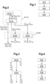
La
Ce procédé débute par une étape E10 de définition des besoins de correction sphérique et cylindrique d'un porteur pour au moins deux proximités de vision, ici en vision de loin et en vision de près. On pourrait en variante définir les besoins de correction du porteur pour au moins une autre proximité de vision, par exemple la vision intermédiaire.This process begins with a step E10 of defining the spherical and cylindrical correction needs of a wearer for at least two vision proximities, here in far vision and in near vision. Alternatively, we could define the correction needs of the wearer for at least one other proximity of vision, by example the intermediate vision.
Deux exemples envisageables pour la mise en oeuvre de cette étape E10 sont décrits ci-dessous en référence respectivement aux
Les besoins en correction du porteur sont par exemple exprimés comme suit, pour au moins un oeil (noté X ci-dessous, qui peut être l'œil droit OD ou l'œil gauche OG) :
- une valeur de puissance sphérique RX visant à corriger un défaut de réfraction sphérique en vision de loin (déterminée en général pour chaque oeil) ;
- un vecteur de puissance cylindrique
CX représentant le module et l'angle de la correction cylindrique visant à corriger un défaut de réfraction cylindrique (astigmatisme) en vision de loin (déterminée en général pour chaque œil) ; - l'addition de puissance sphérique équivalente AEX pour une autre proximité de vision (ici la vision de près) que la vision de loin, qui représente la différence entre la valeur de puissance sphérique équivalente pour l'autre proximité de vision (ici la vision de près) et la valeur de puissance sphérique équivalente Req pour la vision de loin ;
- la variation (vectorielle)
VCX du vecteur de puissance cylindrique pour une autre proximité de vision (ici la vision de près) que la vision de loin, qui représente la différence vectorielle entre le vecteur
CX représentant la correction cylindrique en vision de loin.
- a spherical power value R
- a cylindrical power vector
C representing the module and the angle of the cylindrical correction aimed at correcting a cylindrical refractive error (astigmatism) in distance vision (generally determined for each eye); - the addition of equivalent spherical power AE near) and the equivalent spherical power value R eq for distance vision;
- variation (vector)
VC of the cylindrical power vector for another proximity of vision (here near vision) than far vision, which represents the vector difference between the vectorC representing the cylindrical correction in distance vision.
Autrement dit, on a la relation vectorielle suivante : ![]()
![]()
La puissance sphérique équivalente (ou moyenne) est égale à la somme de la puissance sphérique et de la moitié du module du vecteur de puissance cylindrique ; pour la vision de loin : Req = RX + ||
Le procédé se poursuit par une étape E20 de détermination des puissances sphériques et cylindriques de deux lentilles ophtalmiques (chaque lentille ophtalmique étant destinée à être placée devant un oeil du porteur) en des points de vision de différentes proximités, ici en vision de près et en vision de loin, en fonction des besoins définis à l'étape E10.The method continues with a step E20 of determining the spherical and cylindrical powers of two ophthalmic lenses (each ophthalmic lens being intended to be placed in front of one eye of the wearer) at points of vision of different proximities, here in near vision and in distance vision, depending on the needs defined in step E10.
Des puissances sphériques et cylindriques pourraient être déterminées pour des points correspondant à au moins une autre proximité de vision (par exemple la vision intermédiaire) en utilisant les besoins définis pour cette autre proximité de vision dans la variante déjà mentionnée.Spherical and cylindrical powers could be determined for points corresponding to at least one other vision proximity (for example intermediate vision) using the needs defined for this other vision proximity in the variant already mentioned.
Pour au moins une des deux lentilles ophtalmiques, les puissances sphériques et cylindriques sont déterminées à l'étape E20 notamment de manière à limiter l'écart entre l'addition de puissance sphérique équivalente pour l'œil droit AEOD et l'addition de puissance sphérique équivalente pour l'œil gauche AEOG, et/ou de manière à limiter l'écart entre la variation du vecteur de puissance cylindrique pour l'œil droit
Deux exemples envisageables pour la mise en oeuvre de cette étape E20 sont décrits ci-dessous en référence respectivement aux
L'étape E20 est suivie d'une étape E30 de réalisation des lentilles ophtalmiques sur la base des puissances sphériques et cylindriques déterminées à l'étape E20.Step E20 is followed by a step E30 of producing ophthalmic lenses on the basis of the spherical and cylindrical powers determined in step E20.
Comme cela ressortira de l'exemple de mise en oeuvre de cette étape donné ci-dessous pour une lentille en référence à la
La
Un tel procédé comprend une première étape E110 de définition des besoins de correction sphérique et cylindrique du porteur (qui correspond à l'étape E10 décrite ci-dessus) et une seconde étape E120 de détermination des puissances sphériques et cylindriques pour deux lentilles ophtalmiques destinées à être placées devant les yeux du porteur (l'étape E120 correspondant à l'étape E20 décrite ci-dessus).Such a method comprises a first step E110 of defining the spherical and cylindrical correction needs of the wearer (which corresponds to step E10 described above) and a second step E120 of determining the spherical and cylindrical powers for two ophthalmic lenses intended to be placed in front of the wearer's eyes (step E120 corresponding to step E20 described above).
La première étape E110 débute par une sous-étape E112 de prescription de certaines valeurs de correction par un optométriste :
- des valeurs de correction en vision de loin (notamment, pour chaque oeil X, une valeur de puissance sphérique RX et un vecteur de puissance cylindrique
CX ), généralement basées sur des mesures effectuées par l'optométriste sur le porteur (réfraction monoculaire, correction d'astigmatisme, équilibre bioculaire, appréciation perceptuelle), sur des plaintes et les besoins visuels du porteur et sur la vision binoculaire ; - une valeur d'addition standard AST (relative à une autre proximité de vision, ici la vision de près), qui tient généralement compte de l'âge du porteur, de sa distance de travail et de sa capacité d'accommodation, et qui est utilisée pour les deux yeux (la puissance sphérique positive pour cette addition standard étant ajoutée symétriquement sur les deux yeux).
- far vision correction values (in particular, for each eye X, a spherical power value R
C ), generally based on measurements carried out by the optometrist on the wearer (monocular refraction, astigmatism correction, biocular balance, perceptual assessment), on complaints and the visual needs of the wearer and on binocular vision; - a standard addition value A ST (relating to another vision proximity, here near vision), which generally takes into account the age of the wearer, their working distance and their accommodation capacity, and which is used for both eyes (the positive spherical power for this standard addition being added symmetrically across both eyes).
La première étape E112 est suivie d'une sous-étape E114 de mesure de la réfraction subjective pour cette autre proximité de vision (ici la vision de près), à l'aide d'un outil adapté à ce type de mesure, par exemple une tête de réfraction ou des lunettes d'essai.The first step E112 is followed by a sub-step E114 of measuring the subjective refraction for this other proximity of vision (here near vision), using a tool adapted to this type of measurement, for example a refraction head or trial glasses.
Grâce à un tel outil, on mesure à l'étape E114 la réfraction monoculaire de chaque oeil à la distance d'observation voulue (axe de regard et proximité souhaitée, ici vision de près) : puissance sphérique, axe de cylindre, puissance cylindrique, puis éventuellement vérification de la puissance sphérique.Using such a tool, in step E114 the monocular refraction of each eye is measured at the desired observation distance (gaze axis and desired proximity, here near vision): spherical power, cylinder axis, cylindrical power, then possibly checking the spherical power.
On peut alors procéder à un équilibrage des puissances sphériques entre les deux yeux (équilibre binoculaire) afin d'égaliser l'accommodation mise en jeu lors de la réfraction monoculaire ; en effet, les deux yeux sont généralement testés à des moments différents et il est possible que le couple oculaire n'ait pas eu le même degré de relâchement accommodatif pendant l'examen de l'un ou l'autre oeil.We can then proceed to balance the spherical powers between the two eyes (binocular balance) in order to equalize the accommodation involved during monocular refraction; indeed, the two eyes are generally tested at different times and it is possible that the ocular pair did not have the same degree of accommodative relaxation during the examination of one or the other eye.
Différentes méthodes d'équilibrage de la puissance sphérique peuvent être utilisées (prismes verticaux, filtres polarisés, occlusion alternée, septum). Avec chaque méthode de dissociation, l'état accommodatif des deux yeux peut être comparé selon l'une des méthodes suivantes : méthode des optotypes, flou des images, équilibre sur duochrome.Different spherical power balancing methods can be used (vertical prisms, polarized filters, alternating occlusion, septum). With each dissociation method, the accommodative state of the two eyes can be compared using one of the following methods: optotype method, image blur, duochrome balance.
La sous-étape E114 inclut éventuellement en outre une mesure de la performance visuelle (par exemple une mesure de l'acuité visuelle monoculaire et/ou binoculaire) avant et après cette mesure de réfraction monoculaire en vision de près (par exemple avec des lunettes d'essai apportant une correction correspondant aux puissances mesurées) afin de s'assurer que la prise en compte de la réfraction monoculaire améliore la performance visuelle.Substep E114 optionally also includes a measurement of visual performance (for example a measurement of monocular and/or binocular visual acuity) before and after this measurement of monocular refraction in near vision (for example with glasses of test providing a correction corresponding to the measured powers) in order to ensure that the taking into account Monocular refraction improves visual performance.
La sous-étape E114 permet donc d'obtenir, pour chaque oeil X, l'addition de puissance sphérique équivalente AEX pour l'autre proximité de vision (ici la vision de près) et la variation
Selon une variante envisageable pour l'étape E114, seule la correction de puissance cylindrique est mesurée pour l'autre proximité de vision (ici la vision de près) de sorte que l'étape E114 permet seulement de définir, pour chaque oeil X, la variation
Selon d'autres modes de réalisation envisageable pour l'étape E110 :
- l'ensemble des données (besoins de correction sphérique et cylindrique) pour les différentes proximités de vision (vision de loin et vision de près dans l'exemple décrit ici) sont recueillies de manière objective à l'aide d'un aberromètre ou d'un auto-refractomètre ;
- l'ensemble des données (besoins de correction sphérique et cylindrique) pour les différentes proximités de vision (vision de loin et vision de près dans l'exemple décrit ici) sont recueillies de manière subjective par un optométriste ;
- les besoins de correction sphérique et cylindrique pour la vision de loin sont déterminés, de manière subjective, par un optométriste et les besoins de correction sphérique et cylindrique pour une autre proximité de vision (ici la vision de près) sont déterminés, de manière objective, par un aberromètre ou un auto-refractomètre ;
- les besoins de correction sphérique et cylindrique pour la vision de loin sont déterminés de manière subjective par un optométriste et ceux relatifs à une autre proximité de vision (ici la vision de près) sont déterminés par l'ajout, à la prescription en vision de loin subjective, de l'écart mesuré de manière objective entre vision de loin et vision de près à l'aide d'un aberromètre ou d'un auto-refractomètre.
- all the data (spherical and cylindrical correction needs) for the different vision proximities (far vision and near vision in the example described here) are collected objectively using an aberrometer or an auto-refractometer;
- all the data (spherical and cylindrical correction needs) for the different vision proximities (far vision and near vision in the example described here) are collected subjectively by an optometrist;
- the spherical and cylindrical correction needs for distance vision are determined, subjectively, by an optometrist and the spherical and cylindrical correction needs for other near vision (here near vision) are determined, objectively, by an aberrometer or auto-refractometer;
- the spherical and cylindrical correction needs for distance vision are determined subjectively by an optometrist and those relating to another near vision (here near vision) are determined by adding to the prescription for distance vision subjective, of the gap measured objectively between distance vision and near vision using an aberrometer or an auto-refractometer.
Une fois les besoins de correction sphérique et cylindrique définis (étape E110 formée par exemple des sous-étapes E112 et E114), on procède à l'étape E120 de détermination des puissances sphériques et cylindriques pour les deux lentilles ophtalmiques.Once the spherical and cylindrical correction needs have been defined (step E110 formed for example by sub-steps E112 and E114), we proceed to step E120 for determining the spherical and cylindrical powers for the two ophthalmic lenses.
Dans l'exemple décrit ici, on utilise directement les besoins de correction sphérique et cylindrique en vision de loin (c'est-à-dire les valeurs de puissance sphérique ROD, ROG et les vecteurs de puissance cylindrique
On traite en revanche les deux valeurs d'addition de puissance sphérique équivalente AEOD, AEOG, obtenues respectivement pour l'œil droit et l'œil gauche à l'étape E114, au moyen d'une sous-étape E122 de limitation de l'écart entre ces deux valeurs (cet écart pouvant s'écrire comme la valeur absolue de la différence entre les deux valeurs : |AEOD - AEOG|).On the other hand, we treat the two equivalent spherical power addition values AE OD , AE OG , obtained respectively for the right eye and the left eye in step E114, by means of a sub-step E122 of limitation of the difference between these two values (this difference can be written as the absolute value of the difference between the two values: |AE OD - AE OG |).
Si cet écart est (strictement) supérieur à un seuil prédéfini (par exemple 0,325 dioptrie ou 0,25 dioptrie, voire 0,125 dioptrie), on modifie au moyen de l'étape E122 au moins une des deux valeurs d'addition de puissance sphérique équivalente AEOD, AEOG de sorte que l'écart (en tenant compte de la valeur modifiée) soit inférieur ou égal au seuil prédéfini, voire nul.If this difference is (strictly) greater than a predefined threshold (for example 0.325 diopter or 0.25 diopter, or even 0.125 diopter), at least one of the two equivalent spherical power addition values is modified by means of step E122. AE OD , AE OG so that the deviation (taking into account the modified value) is less than or equal to the predefined threshold, or even zero.
On peut éventuellement prendre en compte, lors de la modification de valeur d'addition de puissance sphérique équivalente de l'étape E122, la valeur d'addition standard AST déterminée à l'étape E112, par exemple en modifiant lors de l'étape E122 la valeur d'addition de puissance sphérique la plus éloignée de la valeur d'addition standard AST.It is possible to take into account, when modifying the equivalent spherical power addition value of step E122, the standard addition value A ST determined in step E112, for example by modifying during step E122 the spherical power addition value farthest from the standard addition value A ST .
Ainsi, par exemple, si les besoins définis à l'étape E110 sont les suivants : AST = 2,25 dioptrie, AEOD = 2,5 dioptrie, AEOG = 2,75 dioptrie, on modifie la valeur d'addition de puissance sphérique équivalente pour l'œil gauche AEOG (la plus éloignée de la valeur d'addition standard AST) de manière à réduire l'écart entre AEOD et AEOG, en prenant par exemple comme valeur modifiée d'addition de puissance sphérique équivalente pour l'œil gauche AE'OG = 2,5 dioptrie.Thus, for example, if the needs defined in step E110 are as follows: A ST = 2.25 diopter, AE OD = 2.5 diopter, AE OG = 2.75 diopter, we modify the addition value of equivalent spherical power for the left eye AE OG (farthest from the standard addition value A ST ) so as to reduce the gap between AE OD and AE OG , taking for example as a modified power addition value spherical equivalent for the left eye AE' OG = 2.5 diopters.
Les valeurs AE'OG, AE'OD d'addition de puissance sphérique équivalente après traitement par l'étape E122 (c'est-à-dire éventuellement modifiées par ce traitement) sont utilisées, en complément des valeurs de puissance sphérique ROD, ROG en vision de loin, pour obtenir les puissances sphériques sur les zones de lentilles ophtalmiques qui correspondent à l'autre proximité de vision caractérisée par cette addition, ici la vision de près.The values AE' OG , AE' OD of equivalent spherical power addition after processing by step E122 (that is to say possibly modified by this treatment) are used, in addition to the spherical power values R OD , R OG in distance vision, to obtain the spherical powers on the ophthalmic lens zones which correspond to the other near vision characterized by this addition, here the vision from close.
On évite ainsi l'inconfort qui pourrait être causé au porteur du fait d'une prescription d'addition de puissance sphérique différenciée (oeil droit/oeil gauche) trop marquée.This avoids the discomfort that could be caused to the wearer due to a prescription for differentiated spherical power addition (right eye/left eye) that is too marked.
Selon une variante envisageable pour l'étape E122, le traitement effectué par cette étape consiste à modifier au moins une des deux valeurs d'addition de puissance sphérique équivalente AEOD, AEOG de manière à annuler toute différence entre ces deux valeurs, par exemple en prenant pour les deux yeux (et donc notamment pour l'œil Y non-dominant en vision de loin) la valeur d'addition équivalente AEZ mesurée à l'étape E114 pour l'œil dominant Z.According to a possible variant for step E122, the processing carried out by this step consists of modifying at least one of the two equivalent spherical power addition values AE OD , AE OG so as to cancel any difference between these two values, for example by taking for both eyes (and therefore in particular for the non-dominant eye Y in distance vision) the equivalent addition value AE Z measured in step E114 for the dominant eye Z.
On a donc dans ce cas les valeurs suivantes après traitement par l'étape E122 : AE'OG=AE'OD=AEZ (seule la valeur AEY pour l'œil non-dominant étant donc modifiée par cette étape).We therefore have in this case the following values after processing by step E122: AE' OG =AE' OD =AE Z (only the AE Y value for the non-dominant eye is therefore modified by this step).
Selon une autre variante envisageable pour l'étape E122, le traitement effectué à cette étape (qui peut éventuellement être combiné aux traitements proposés ci-dessus) consiste à modifier éventuellement chaque valeur d'addition de puissance sphérique équivalente AEOD, AEOG obtenue à l'étape E114 de sorte que l'écart entre cette valeur AEOD, AEOG et la valeur d'addition standard AST obtenue à l'étape E112 soit inférieur ou égal à un seuil prédéfini, par exemple 0,25 dioptrie.According to another possible variant for step E122, the processing carried out at this step (which can possibly be combined with the processing proposed above) consists of possibly modifying each equivalent spherical power addition value AE OD , AE OG obtained at step E114 so that the difference between this value AE OD , AE OG and the standard addition value A ST obtained in step E112 is less than or equal to a predefined threshold, for example 0.25 diopters.
On remarque que cette variante permet également de limiter l'écart entre les deux valeurs d'addition de puissance sphérique équivalente AEOD, AEOG puisque, après modification éventuelle afin d'être toutes deux suffisamment proches de la valeur d'addition standard AST, les valeurs d'addition de puissance sphérique équivalente AE'OD, AE'OG obtenues à l'issue de l'étape E112 seront nécessairement proches l'une de l'autre.Note that this variant also makes it possible to limit the difference between the two equivalent spherical power addition values AE OD , AE OG since, after possible modification in order to be both sufficiently close to the standard addition value A ST , the equivalent spherical power addition values AE' OD , AE' OG obtained at the end of step E112 will necessarily be close to each other.
Selon une autre variante envisageable pour l'étape E122, le traitement effectué à cette étape consiste à modifier éventuellement chaque valeur d'addition de puissance sphérique équivalente AEOD, AEOG de manière à annuler toute différence entre chacune de ces deux valeurs AEOD, AEOG et la valeur d'addition standard AST obtenue à l'étape E112.According to another possible variant for step E122, the processing carried out in this step consists of possibly modifying each equivalent spherical power addition value AE OD , AE OG so as to cancel any difference between each of these two values AE OD , AE OG and the standard addition value A ST obtained in step E112.
On traite également les deux variations du vecteur de puissance cylindrique
Selon un premier mode de réalisation envisageable pour la sous-étape E124, on applique les règles de traitement suivantes :
- si le module ∥
VCZ ∥ de la variation du vecteur de puissance cylindrique pour l'œil dominant Z est inférieur à un premier seuil prédéfini (ici 0,15 dioptrie), alors le module ∥VCY ∥ de la variation du vecteur de puissance cylindrique pour l'œil non-dominant Y est limité à un second seuil prédéfini, valant par exemple le double du premier seuil prédéfini (ici le second seuil vaut 0,30 dioptrie) ; - si le module ∥
VCZ ∥ de la variation du vecteur de puissance cylindrique pour l'œil dominant Z est supérieur (ou égal) au premier seuil prédéfini (ici 0,15 dioptrie), alors le module ∥VCY ∥ de la variation du vecteur de puissance cylindrique pour l'œil non-dominant Y est limité proportionnellement au module ∥VCZ ∥ de la variation du vecteur de puissance cylindrique pour l'œil dominant Z, par exemple au double du module ∥VCZ ∥ de la variation du vecteur de puissance cylindrique pour l'œil dominant Z.
- if the module ∥
VC Z ∥ of the variation of the cylindrical power vector for the dominant eye Z is less than a first predefined threshold (here 0.15 diopter), then the module ∥VC Y ∥ of the variation of the cylindrical power vector for the non-dominant eye Y is limited to a second predefined threshold, for example worth twice the first predefined threshold (here the second threshold is worth 0.30 diopters); - if the module ∥
VC Z ∥ of the variation of the cylindrical power vector for the dominant eye Z is greater (or equal) to the first predefined threshold (here 0.15 diopter), then the module ∥VC Y ∥ of the variation of the cylindrical power vector for the non-dominant eye Y is limited proportionally to the module ∥VC Z ∥ of the variation of the cylindrical power vector for the dominant eye Z, for example twice the module ∥VC Z ∥ of the variation of the cylindrical power vector for the dominant eye Z.
Autrement dit, si l'on note
- si ∥
VCZ ∥ < 0,15 et ∥VCY ∥ < 0,3, alorsVC'Y =VCY (la variation du vecteur de puissance cylindrique pour l'œil non-dominant est alors inchangée par l'étape E124) ; - si ∥
VCZ ∥ < 0,15 et ∥VCY ∥ ≥ 0,3, alorsVC'Y est choisi tel que: ∥VC'Y ∥ = 0,3 (l'angle du vecteurVC' Y étant identique à celui du vecteurVCY ); - si ∥
VCZ ∥ ≥ 0,15 et ∥VCY ∥ < 2.∥VCZ ∥, alorsVC'Y =VCY (la variation du vecteur de puissance cylindrique pour l'œil non-dominant est alors inchangée par l'étape E124) ; - si ∥
VCZ ∥ ≥ 0,15 et ∥VCY ∥ ≥ 2.∥VCZ ∥, alorsVC'Y est choisi tel que : ∥VC'Y ∥ = 2.∥VCZ ∥ (l'angle du vecteurVC'Y étant identique à celui du vecteurVCY ).
- if ∥
VC Z ∥ < 0.15 and ∥VC Y ∥ < 0.3, thenVC' Y =VC Y (the variation of the cylindrical power vector for the non-dominant eye is then unchanged by step E124); - if ∥
VC Z ∥ < 0.15 and ∥VC Y ∥ ≥ 0.3, thenVC' Y is chosen such that: ∥VC' Y ∥ = 0.3 (the angle of the vectorVC'Y being identical to that of the vectorVC Y ); - if ∥
VC Z ∥ ≥ 0.15 and ∥VC Y ∥ < 2.∥VC Z ∥, thenVC' Y =VC Y (the variation of the cylindrical power vector for the non-dominant eye is then unchanged by step E124); - if ∥
VC Z ∥ ≥ 0.15 and ∥VC Y ∥ ≥ 2.∥VC Z ∥, thenVC' Y is chosen such that: ∥VC' Y ∥ = 2.∥VC Z ∥ (the angle of the vectorVC' Y being identical to that of the vectorVC Y ).
On remarque que, dans ce mode de réalisation, la variation du vecteur de puissance cylindrique
On a en effet remarqué que la mesure réalisée à l'étape E122 définissait en général un plus fort besoin de variation du vecteur de puissance cylindrique pour l'œil non-dominant Y mais également qu'une variation du vecteur de puissance cylindrique trop déséquilibrée (entre l'œil droit OD et l'œil gauche OG) produisait un inconfort pour le porteur, ce qui est évité grâce aux règles de traitement ci-dessus.It was indeed noted that the measurement carried out in step E122 generally defined a greater need for variation of the cylindrical power vector for the non-dominant eye Y but also that a variation of the cylindrical power vector that was too unbalanced ( between the right eye OD and the left eye OG) produced discomfort for the wearer, which is avoided by the treatment rules above.
Selon un second mode de réalisation envisageable pour la sous-étape E124, le traitement effectué consiste à limiter la variation du vecteur de puissance cylindrique dont le module est maximum, en tenant compte de la variation du vecteur de puissance cylindrique dont le module est minimum. (Aucune modification n'est apportée aux variations du vecteur de puissance cylindrique si leurs deux modules sont égaux.)According to a second possible embodiment for sub-step E124, the processing carried out consists of limiting the variation of the cylindrical power vector whose module is maximum, taking into account the variation of the cylindrical power vector whose module is minimum. (No modification is made to the variations of the cylindrical power vector if their two moduli are equal.)
Autrement dit, si on note I l'œil pour lequel le module de la variation du vecteur de puissance cylindrique est minimum (I est tel que : ∥
- si ∥
VCI ∥ < 0,15 et ∥VCJ ∥ < 0,3, alorsVC'J =VCJ ; - si ∥
VCI ∥ < 0,15 et ∥VCJ ∥ ≥ 0,3, alorsVC'J est choisi tel que: ∥VC'J ∥ = 0,3 (l'angle du vecteurVC'J étant identique à celui du vecteurVCJ ) ; - si ∥
VCI ∥ > 0,15 et ∥VCJ ∥ < 2.∥VCI ∥, alorsVC'J =VCJ ; - si ∥
VCI ∥ ≥ 0,15 et ∥VCJ ∥ ≥ 2.∥VCI ∥, alorsVC'J est choisi tel que : ∥VC'J ∥ = 2.∥VCI ∥ (l'angle du vecteurVC'J étant identique à celui du vecteurVCJ ).
- if ∥
VC I ∥ < 0.15 and ∥VC J ∥ < 0.3, thenVC' J =VC J ; - if ∥
VC I ∥ < 0.15 and ∥VC J ∥ ≥ 0.3, thenVC' J is chosen such that: ∥VC' J ∥ = 0.3 (the angle of the vectorVC' J being identical to that of the vectorVC J ) ; - if ∥
VC I ∥ > 0.15 and ∥VC J ∥ < 2.∥VC I ∥, thenVC' J =VC J ; - if ∥
VC I ∥ ≥ 0.15 and ∥VC J ∥ ≥ 2.∥VC I ∥, thenVC' J is chosen such that: ∥VC' J ∥ = 2.∥VC I ∥ (the angle of the vectorVC' J being identical to that of the vectorVC J ).
On propose dans ce mode de réalisation de ne pas modifier la variation du vecteur de puissance cylindrique
Selon un troisième mode de réalisation envisageable pour la sous-étape E124, la variation du vecteur de puissance cylindrique
Quel que soit le mode de réalisation mis en oeuvre, les variations du vecteur de puissance cylindrique
L'étape E120 inclut éventuellement en outre, après les traitements des étapes E122 et E124 qui viennent d'être décrits, une mesure de la performance visuelle (par exemple une mesure de l'acuité visuelle monoculaire et/ou binoculaire, typiquement avec des lunettes d'essai apportant une correction correspondant aux puissances déterminées) afin de s'assurer que la prise en compte des variations du vecteur de puissance cylindrique pour la vision de près améliore la performance visuelle.Step E120 optionally also includes, after the processing of steps E122 and E124 which have just been described, a measurement of visual performance (for example a measurement of monocular and/or binocular visual acuity, typically with glasses test providing a correction corresponding to the determined powers) in order to ensure that taking into account variations in the cylindrical power vector for near vision improves visual performance.
Selon une variante envisageable, plutôt que de réaliser toutes les actions de l'étape E114 puis ensuite celles de l'étape E120 comme décrit ci-dessus, on pourrait procéder comme suit :
- réaliser dans l'étape E114 seulement les actions relatives à la correction sphérique (notamment la détermination des valeurs d'addition de puissance sphérique équivalente AEOD, AEOG) ;
- réaliser les actions de la sous-étape E122 (limitation des écarts pour l'addition de puissance sphérique équivalente) ;
- réaliser dans l'étape E114 les actions relatives à la correction cylindrique (en tenant compte des valeurs d'addition de puissance sphérique équivalente modifiées AE'OD, AE'OG obtenues au moyen de la sous-étape E122, ce qui permet d'améliorer les mesures effectuées lors de la présente étape) ;
- réaliser les actions de la sous-étape E124.
- carry out in step E114 only the actions relating to the spherical correction (in particular the determination of the equivalent spherical power addition values AE OD , AE OG );
- carry out the actions of sub-step E122 (limiting the deviations for the addition of equivalent spherical power);
- carry out in step E114 the actions relating to the cylindrical correction (taking into account the modified equivalent spherical power addition values AE' OD , AE' OG obtained by means of sub-step E122, which makes it possible to improve the measurements taken during this step);
- carry out the actions of sub-step E124.
La
Un tel procédé comprend une première étape E210 de définition des besoins de correction sphérique et cylindrique du porteur (qui correspond à l'étape E10 décrite ci-dessus) et une seconde étape E220 de détermination des puissances sphériques et cylindriques pour deux lentilles ophtalmiques destinées à être placées devant les yeux du porteur (la seconde étape E220 correspondant à l'étape E20 décrite ci-dessus).Such a method comprises a first step E210 of defining the spherical and cylindrical correction needs of the wearer (which corresponds to step E10 described above) and a second step E220 of determining the spherical and cylindrical powers for two ophthalmic lenses intended to be placed in front of the eyes of the wearer (the second step E220 corresponding to step E20 described above).
L'étape E210 comprend la mesure pour un seul des deux yeux du porteur, ici l'œil dominant Z (pour lequel les mesures sont en général plus stables), des besoins en correction sphérique et cylindrique, pour plusieurs proximités de vision (ici en vision de loin et en vision de près).Step E210 includes the measurement for only one of the wearer's two eyes, here the dominant eye Z (for which the measurements are generally more stable), of the spherical and cylindrical correction needs, for several vision proximities (here in distance vision and near vision).
Ceci permet donc de définir :
- la valeur de puissance sphérique RZ de correction en vision de loin pour l'œil dominant Z ;
- le vecteur de puissance cylindrique
CZ de correction en vision de loin pour l'œil dominant Z ; - l'addition de puissance sphérique équivalente AEZ pour une autre proximité de vision (ici la vision de près) ;
- la variation
VCZ du vecteur de puissance cylindrique pour l'autre proximité de vision (ici la vision de près).
- the spherical power value R Z for far vision correction for the dominant eye Z;
- the cylindrical power vector
C Z far vision correction for the dominant eye Z; - the addition of equivalent spherical power AE Z for another vision proximity (here near vision);
- variation
VC Z of the cylindrical power vector for the other vision proximity (here near vision).
On réalise également à l'étape E210 des mesures en vision de loin pour l'autre oeil, ici l'œil non-dominant Y, ce qui permet de définir :
- la valeur de puissance sphérique RY de correction en vision de loin pour l'œil non-dominant Y ;
- le vecteur de puissance cylindrique
CY de correction en vision de loin pour l'œil non-dominant Y.
- the spherical power value R Y for far vision correction for the non-dominant eye Y;
- the cylindrical power vector
C Y far vision correction for the non-dominant eye Y.
On utilise par exemple pour ces mesures les mêmes techniques que celles décrites plus haut en référence à l'étape E114 (appliquées cette fois à la vision de loin et à la vision de près).For example, for these measurements we use the same techniques as those described above with reference to step E114 (this time applied to distance vision and near vision).
Au cours de l'étape E220, on utilise les résultats de l'étape E210 sans modification afin de déterminer les puissances sphérique et cylindrique des deux lentilles ophtalmiques.During step E220, the results of step E210 are used without modification in order to determine the spherical and cylindrical powers of the two ophthalmic lenses.
Toutefois, afin de déterminer les puissances sphérique et cylindrique pour la vision de près pour la lentille ophtalmique associée à l'œil pour lequel aucune mesure n'a été effectuée en vision de près (ici l'œil non-dominant Y), on détermine comme suit au cours de l'étape E220 l'addition de puissance sphérique équivalente AEY et la variation du vecteur de puissance cylindrique
- l'addition de puissance sphérique équivalente AEY est choisie égale à celle relative à l'autre oeil AEZ;
- la variation du vecteur de puissance cylindrique
VCY est choisie de sorte que son module soit proche ou identique du module ∥VCZ ∥ de la variation du vecteur de puissance cylindrique relative à l'autre oeil, son orientation étant choisi de façon à obtenir une variation d'angle de correction cylindrique de signe opposé sur les deux yeux.
- the addition of equivalent spherical power AE Y is chosen equal to that relating to the other eye AE Z ;
- the variation of the cylindrical power vector
VC Y is chosen so that its modulus is close to or identical to the modulus ∥VC Z ∥ of the variation of the cylindrical power vector relative to the other eye, its orientation being chosen so as to obtain a variation of cylindrical correction angle of opposite sign on the two eyes.
Par exemple, dans le cas décrit ici où l'œil pour lequel les mesures ont été effectuées est l'œil dominant Z :
- si ∥
VCZ ∥ < 0,15, alors on choisitVCY tel que ∥VCY ∥ < 0,3 ; - si ∥
VCZ ∥ ≥ 0,15, alors on choisitVCY tel que ∥VCY ∥ < 2.∥VCZ ∥.
- if ∥
VC Z ∥ < 0.15, then we chooseVC Y such that ∥VC Y ∥ <0.3; - if ∥
VC Z ∥ ≥ 0.15, then we chooseVC Y such that ∥VC Y ∥ < 2.∥VC Z ∥.
En variante, lorsque l'œil pour lequel les mesures ont été effectuées est l'œil non-dominant Y (auquel cas la variation du vecteur de puissance cylindrique ![]()
![]()
Selon une variante envisageable, on peut prévoir au cours de l'étape E220 que l'addition de puissance sphérique équivalente AEZ obtenue à l'étape E210 soit éventuellement modifiée de manière à limiter l'écart entre cette valeur AEZ et l'addition standard AST (mentionnée plus haut dans le cadre de la description de la
La
Ce procédé débute par une étape E32 de détermination d'une loi de variation cible pour la correction de puissance cylindrique.This method begins with a step E32 of determining a target variation law for the cylindrical power correction.
On note α et β les angles qui définissent une direction du regard par rapport au centre de rotation de l'œil : α est l'angle formé entre la direction du regard et le plan horizontal contenant le centre de rotation de l'œil ; β est l'angle formé entre la direction du regard et le plan vertical contenant le centre de rotation de l'œil.We note α and β the angles which define a direction of gaze relative to the center of rotation of the eye: α is the angle formed between the direction of gaze and the horizontal plane containing the center of rotation of the eye; β is the angle formed between the direction of gaze and the vertical plane containing the center of rotation of the eye.
On définit lors de l'étape E32 la correction cylindrique (module, axe) à apporter pour l'ensemble des directions de regard traversant (dans les conditions standards de port des lunettes, dites "au porté") la lentille ophtalmique, sur la base des puissances prescrites obtenues à l'étape E20.We define during step E32 the cylindrical correction (module, axis) to be made for all the directions of gaze passing through (under the standard conditions of wearing glasses, called " when worn ") the ophthalmic lens, on the basis prescribed powers obtained in step E20.
Dans l'exemple décrit ici, on définit 3 zones :
- les directions du regard pour lesquelles α < αmin (quel que soit β), qui correspondent à la vision de loin ;
- les directions du regard pour lesquelles α > αmax (quel que soit β), qui correspondent à la vision de près ;
- les directions du regard pour lesquelles αmin ≤ α ≤ αmax, qui correspondent à une zone intermédiaire.
- the gaze directions for which α < α min (whatever β), which correspond to distance vision;
- the gaze directions for which α > α max (whatever β), which correspond to near vision;
- the gaze directions for which α min ≤ α ≤ α max , which correspond to an intermediate zone.
Selon une première possibilité de réalisation, on utilise une loi de variation linéaire selon α dans la zone intermédiaire pour définir le module et l'axe de la correction cylindrique à apporter.According to a first possibility of realization, we use a law of linear variation according to α in the intermediate zone to define the module and the axis of the cylindrical correction to be made.
Si on note X l'œil correspondant à la lentille ophtalmique construite ici, et Cyl et Axe respectivement les valeurs de module et d'angle de correction cylindrique souhaitée, on a alors :
- Cyl(α) = ∥
CX ∥ et Axe(α) = argCX pour α < αmin (où argV est la fonction qui donne l'angle du vecteurV ) ; - Cyl(α) = λ(α).∥
CX ∥ + µ(α).∥CX +VCX ∥ et Axe(α) = λ(α).argCX + µ(α).arg(CX +VCX ) pour αmin ≤ α ≤ αmax, avec λ(α)=(αmax-α)/(αmax-αmin) et µ(α)=(α-αmin)/( αmax-αmin) ; - Cyl(α) = ∥
CX +VCX ∥ et Axe(α) = arg(CX +VCX ) pour α > αmax.
- Cyl(α) = ∥
C ∥ and Axis(α) = argC for α < α min (where argV is the function which gives the angle of the vectorV ); - Cyl(α) = λ(α).∥
C ∥ + µ(α).∥C +VC ∥ and Ax(α) = λ(α).argC + µ(α).arg(C +VC ) for α min ≤ α ≤ α max , with λ(α)=(α max -α)/(α max -α min ) and µ(α)=(α-α min )/(α max -α min ) ; - Cyl(α) = ∥
C +VC ∥ and Ax(α) = arg(C +VC ) for α > α max .
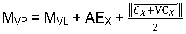
Selon une seconde possibilité de réalisation, on utilise les grandeurs M, J0, J45 classiquement définie comme : M = S + C/2 ; J0 = -(C/2).cos 2A ; J45 = -(C/2).sin 2A, avec S la puissance sphérique, C la puissance cylindrique (module) et A l'angle de cylindre.According to a second possibility of realization, we use the quantities M, J0, J45 classically defined as: M = S + C/2; J0 = -(C/2).cos 2A; J45 = -(C/2).sin 2A, with S the spherical power, C the cylindrical power (modulus) and A the cylinder angle.
On peut ainsi définir les grandeurs suivantes sur la base des puissances prescrites obtenues à l'étape E20 pour l'œil X concerné :
- en vision de loin,


- en vision de près,


- in distant vision,
- in close vision,
On utilise les valeurs MVL, J0VL, J45VL pour la zone correspondant à la vision de loin (α < αmin) et les valeurs MVP, J0VP, J45VP pour la zone correspondant à la vision de près (α > αmax).We use the values M VL , J0 VL , J45 VL for the zone corresponding to far vision (α < α min ) and the values M VP , J0 VP , J45 VP for the zone corresponding to near vision (α > α max ).
Pour la zone intermédiaire (αmin ≤ αi ≤ αmax), on utilise les valeurs suivantes (avec αi = α1βi + b1 où a1 et b1 sont des constantes) : ![]()
![]()
- J45(αi) = λ(αi).J45VL + µ(αi).J45VP, les paramètres λ(αi) et µ(αi) étant définis comme indiqué ci-dessus pour la première possibilité de réalisation.
- J45(α i ) = λ(α i ).J45 VL + µ(α i ).J45 VP , the parameters λ(α i ) and µ(α i ) being defined as indicated above for the first possibility of realization .
Le procédé de la
Selon une première possibilité de réalisation de l'étape E34, on lance un tracé de rayon afin de définir pour chaque direction de regard les points appartenant au profil de la méridienne. Selon cette possibilité, l'étape E34 comprend les sous-étapes suivantes :
- définition d'un ergorama (c'est-à-dire la donnée de la distance de l'objet observé pour chaque direction du regard) ;
- modélisation de la lentille ophtalmique et calcul de la puissance pour chaque direction de regard (α, β) en fonction de la distance objet, sur la base de la loi de variation définie à l'étape E32 ;
- lancé d'un tracé de rayon reliant l'objet au centre de rotation de l'œil ;
- récupération du point d'impact sur la face avant de la lentille ophtalmique.
- definition of an ergorama (i.e. the data on the distance of the object observed for each direction of gaze);
- modeling of the ophthalmic lens and calculation of the power for each direction of gaze (α, β) as a function of the object distance, based on the variation law defined in step E32;
- launched a ray trace connecting the object to the center of rotation of the eye;
- recovery of the point of impact on the front face of the ophthalmic lens.
Chaque point ainsi déterminé par ce processus appartient au profil spatial de la méridienne recherché à l'étape E34.Each point thus determined by this process belongs to the spatial profile of the meridian sought in step E34.
Selon une seconde possibilité de réalisation de l'étape E34, on utilise un modèle prenant en compte les effets prismatiques liés à la puissance du verre (puissance moyenne, astigmatisme et axe) pour chaque direction du regard. On définit ainsi les points appartenant au profil spatial de la méridienne. Connaissant le nouveau profil de méridienne, la définition de la surface peut être cisaillée de façon à être décalée sur ce profil.According to a second possibility of carrying out step E34, we use a model taking into account the prismatic effects linked to the power of the lens (average power, astigmatism and axis) for each direction of gaze. We thus define the points belonging to the spatial profile of the meridian. Knowing the new meridian profile, the surface definition can be sheared so as to be offset on this profile.
On procède alors à une étape E36 d'optimisation de la surface optique de la lentille ophtalmique, par exemple sur la base de la méthode d'atorisation décrite dans la demande de brevet
Dans le cadre de cette méthode, on utilise par exemple comme lentille de référence une lentille possédant les puissances sphériques et cylindriques prescrites, obtenues à l'étape E20, tant pour la vision de loin que pour la vision de près ; la lentille cible correspond à la conception que l'on souhaite fournir au porteur (avec l'optique d'un verre sphérique, par exemple).As part of this method, for example, a lens having the prescribed spherical and cylindrical powers, obtained in step E20, is used as a reference lens, both for distance vision and for near vision; the target lens corresponds to the design that we wish to provide to the wearer (with the optics of a spherical lens, for example).
On met alors en oeuvre la méthode d'optimisation précitée (décrite dans la demande de brevet
Au cours de l'optimisation, les valeurs de puissance sphérique équivalente et d'astigmatisme (module, axe) sont donc déterminées en prenant en compte les prescriptions pour chaque direction de regard, évaluées comme indiqué ci-dessus à partir des puissances sphérique et cylindrique prescrites (obtenues à l'étape E30) et de la loi de variation choisie (ici linéaire, comme expliqué à l'étape E32).During the optimization, the values of equivalent spherical power and astigmatism (module, axis) are therefore determined by taking into account the prescriptions for each direction of gaze, evaluated as indicated above from the prescribed spherical and cylindrical powers (obtained in step E30) and the chosen variation law (here linear, as explained in step E32).
On obtient ainsi une définition optimisée des surfaces de la lentille ophtalmique.We thus obtain an optimized definition of the surfaces of the ophthalmic lens.
Selon une variante envisageable pour l'étape E36, la méthode d'atorisation est mise en oeuvre sans tenir compte de la variation de prescription relative à la puissance cylindrique et des nappes sont ensuite ajoutées pour obtenir la variation de puissance cylindrique requise.According to a possible variant for step E36, the atorization method is implemented without taking into account the prescription variation relating to the cylindrical power and layers are then added to obtain the required cylindrical power variation.
Selon cette variante, la lentille de référence est une lentille possédant les puissances sphériques prescrites, obtenues à l'étape E20, tant pour la vision de loin que pour la vision de près (soit les valeurs RX et AEX pour l'œil X) ; la lentille cible correspond à la conception que l'on souhaite fournir au porteur (avec l'optique d'un verre sphérique, par exemple).According to this variant, the reference lens is a lens having the prescribed spherical powers, obtained in step E20, both for distance vision and for near vision ( i.e. the values R ); the target lens corresponds to the design that we wish to provide to the wearer (with the optics of a spherical lens, for example).
On utilise ensuite une combinaison de nappes de façon à s'approcher au mieux des puissances prescrites obtenues à l'étape E20, comme décrit par exemple dans la demande de brevet
Le procédé de la
La lentille ophtalmique à l'étape E36 peut être une lentille progressive, une lentille régressive, un lentille multifocale du type double ou triple foyers, ou une lentille simple foyer.The ophthalmic lens in step E36 may be a progressive lens, a regressive lens, a multifocal lens of the double or triple focus type, or a single focus lens.
Dans le cas d'une lentille progressive, régressive, ou triple foyers, le verre présente des zones définies de vision de près, de vision intermédiaire et de vision de loin, et l'invention peut s'appliquer en choisissant les points de différentes proximités parmi au moins 2 zones, pour au moins une des 2 grandeurs parmi la grandeur d'addition et/ou la grandeur de variation de cylindre. Par exemple, on peut choisir 2 points de différentes proximités en prenant un point appartenant à la zone de vision de loin, et un autre point appartenant à la zone de vision de près d'un progressif et appliquer l'invention sur les grandeurs d'addition de puissance sphérique équivalente et sur les grandeurs de variation du vecteur de puissance cylindrique.In the case of a progressive, regressive, or triple focus lens, the glass has defined zones of near vision, intermediate vision and far vision, and the invention can be applied by choosing the points of different proximities among at least 2 zones, for at least one of the 2 quantities among the addition quantity and/or the cylinder variation quantity. For example, we can choose 2 points of different proximity by taking a point belonging to the far vision zone, and another point belonging to the vision zone. close view of a progressive and apply the invention on the addition quantities of equivalent spherical power and on the variation quantities of the cylindrical power vector.
Dans le cas d'un verre double foyer, le verre présente des zones définies de vision de près et de vision de loin, et l'invention peut s'appliquer sur la grandeur d'addition et/ou sur la grandeur de variation de cylindre et en choisissant 1 point dans la zone de vision de loin et un second point de différente proximité dans la zone de vision de près.In the case of a bifocal lens, the lens has defined zones of near vision and far vision, and the invention can be applied to the addition magnitude and/or to the cylinder variation magnitude. and by choosing 1 point in the far vision zone and a second point of different proximity in the near vision zone.
Dans le cas d'un verre simple foyer, on peut par exemple appliquer l'invention sur la grandeur de variation de cylindre, en définissant un premier point au centre du verre, correspondant à un usage du verre en vision de loin, et un second point dans une zone inférieure du verre correspondant à un usage du verre en vision de près.In the case of a single-focus lens, the invention can for example be applied to the magnitude of variation of the cylinder, by defining a first point at the center of the lens, corresponding to use of the lens for distance vision, and a second point in a lower area of the lens corresponding to use of the lens in near vision.
Claims (14)
- Method for obtaining a pair of ophthalmic lenses for correcting cylindrical and spherical refractive defects of the two eyes of a wearer, including:- a step (E10) of defining the cylindrical and spherical correction requirements of the wearer for various vision proximities,- a step (E20) of determining cylindrical and spherical powers of said ophthalmic lenses at vision points of various proximities, depending on the previously defined cylindrical and spherical correction requirements of the wearer, and- a step (E30) of producing said ophthalmic lenses on the basis of the cylindrical and spherical powers determined;characterized in that the powers of at least one of the two ophthalmic lenses are determined (E20) so as to limit the discrepancy obtained, between the two ophthalmic lenses of the pair, in at least one of the following quantities:- the equivalent spherical power addition between the vision points of various proximities, and- the variation in the cylindrical power vector between the vision points of various proximities.
- Obtaining method according to Claim 1, wherein the discrepancy obtained in one and/or the other of said quantities is smaller than a predefined threshold value.
- Obtaining method according to Claim 2, wherein the discrepancy obtained between the two ophthalmic lenses of the pair in the equivalent spherical power addition between the vision points of various proximities is smaller than 0.25 dioptres.
- Obtaining method according to one of Claims 1 and 2, wherein the powers of at least one of the two ophthalmic lenses are determined (E20) by applying the following rules:- one of the two ophthalmic lenses of the pair having a minimal variation in the cylindrical power vector, this minimal variation being lower than 0.15 dioptres, the variation in the cylindrical power vector of the other ophthalmic lens of the pair is lower than 0.3 dioptres, or- one of the two ophthalmic lenses of the pair having a minimal variation in the cylindrical power vector, this minimal variation being higher than or equal to 0.15 dioptres, the variation in the cylindrical power vector of the other ophthalmic lens of the pair is lower than twice this minimal variation in the cylindrical power vector.
- Obtaining method according to one of Claims 1 to 4, wherein the discrepancy in the variation in the cylindrical power vector between the vision points of various proximities is obtained by modifying the amplitude and/or the angle of the cylindrical power vector of one of the two ophthalmic lenses of the pair at a near-vision point.
- Obtaining method according to one of Claims 1 to 5, wherein the powers of at least one of the two lenses are also determined so as to limit the difference obtained, for the two ophthalmic lenses of the pair, between the equivalent spherical power addition and the addition requirement.
- Obtaining method according to Claim 6, wherein the difference obtained between the equivalent spherical power addition and the addition requirement is smaller than 0.25 dioptres.
- Obtaining method according to one of Claims 1 to 7, wherein the cylindrical and spherical powers of said at least one of the two ophthalmic lenses at vision points of various proximities are determined in increments of 0.125 dioptres.
- Obtaining method according to one of Claims 1 to 8, wherein the determining step is carried out so that the cylindrical and spherical powers, at the vision points of the various proximities, of the ophthalmic lens intended to be placed in front of the dominant eye of the wearer correspond to the cylindrical and spherical correction requirements at said vision points of the wearer.
- Obtaining method according to one of Claims 1 to 9, wherein said vision points of various proximities correspond to far-vision, intermediate-vision and/or near-vision points of the wearer.
- Obtaining method according to one of Claims 1 to 10, wherein said vision points of various proximities correspond to far-vision and near-vision points of the wearer, and the cylindrical and spherical correction requirements of the wearer are defined on the basis of a measurement of the cylindrical and spherical refraction in far vision and in near vision of the two eyes of the wearer.
- Obtaining method according to one of Claims 1 to 10, wherein said vision points of various proximities correspond to far-vision and near-vision points of the wearer, and the cylindrical and spherical correction requirements of the wearer are defined (E210) on the basis of a measurement of the cylindrical and spherical refraction in far vision of the two eyes of the wearer and of a measurement of the cylindrical and spherical refraction in near vision of at least one eye of the wearer.
- Obtaining method according to Claim 12, wherein said measurement (E210) of the cylindrical and spherical refraction in near vision is performed on the dominant eye of the wearer.
- Obtaining method according to one of Claims 1 to 13, wherein the step of defining the requirements comprises a substep of defining cylindrical correction requirements of the wearer for various vision proximities, which substep is carried out after a step of limiting the discrepancy obtained, between the two ophthalmic lenses of the pair, in the equivalent spherical power addition.
Applications Claiming Priority (1)
| Application Number | Priority Date | Filing Date | Title |
|---|---|---|---|
| PCT/FR2014/052783 WO2016066909A1 (en) | 2014-10-31 | 2014-10-31 | Method for optical design of a pair of ophthalmic lenses and pair of ophthalmic lenses thus obtained |
Publications (2)
| Publication Number | Publication Date |
|---|---|
| EP3213144A1 EP3213144A1 (en) | 2017-09-06 |
| EP3213144B1 true EP3213144B1 (en) | 2024-04-17 |
Family
ID=52023547
Family Applications (1)
| Application Number | Title | Priority Date | Filing Date |
|---|---|---|---|
| EP14811949.8A Active EP3213144B1 (en) | 2014-10-31 | 2014-10-31 | Method for optical design of a pair of ophthalmic lenses and pair of ophthalmic lenses thus obtained |
Country Status (6)
| Country | Link |
|---|---|
| US (1) | US10247963B2 (en) |
| EP (1) | EP3213144B1 (en) |
| CN (1) | CN107077005B (en) |
| BR (1) | BR112017008977B1 (en) |
| CA (1) | CA2966488C (en) |
| WO (1) | WO2016066909A1 (en) |
Families Citing this family (2)
| Publication number | Priority date | Publication date | Assignee | Title |
|---|---|---|---|---|
| EP3663838A1 (en) * | 2018-12-03 | 2020-06-10 | Carl Zeiss Vision International GmbH | Spectacle lens, family of spectacle lenses, method for designing a spectacle lens family and method for producing a spectacle lens |
| EP4078277A1 (en) * | 2019-12-16 | 2022-10-26 | Essilor International | Methods for designing an ophthalmic tinted lens and ophthalmic tinted lenses, and corresponding ophthalmic tinted lens |
Citations (3)
| Publication number | Priority date | Publication date | Assignee | Title |
|---|---|---|---|---|
| US20080100800A1 (en) * | 2006-10-25 | 2008-05-01 | Carl Zeiss Vision Gmbh | Eyeglass prescription method |
| WO2009072528A1 (en) * | 2007-12-04 | 2009-06-11 | Hoya Corporation | Pair of progressive refractive power lens and method for designing same |
| US8807746B2 (en) * | 2010-10-12 | 2014-08-19 | Hoya Lens Manufacturing Philippines Inc. | Spectacle lens, spectacles, and method for manufacturing spectacle lens |
Family Cites Families (17)
| Publication number | Priority date | Publication date | Assignee | Title |
|---|---|---|---|---|
| FR2783938B1 (en) | 1998-09-28 | 2000-11-17 | Essilor Int | TORIC OPHTHALMIC LENSES |
| JP4959087B2 (en) * | 2000-04-25 | 2012-06-20 | ローデンストック.ゲゼルシャフト.ミット.ベシュレンクテル.ハフツング | Progressive spectacle lens calculation method and method for manufacturing this type of spectacle lens |
| FR2858693B1 (en) | 2003-08-08 | 2005-10-28 | Essilor Int | METHOD FOR DETERMINING AN OPHTHALMIC LENS USING AN ASTIGMATISM PRESCRIPTION IN VIEW OF FAR AND IN VISION OF PRES |
| US7797861B2 (en) * | 2006-08-14 | 2010-09-21 | Wright Danny M | Resilient excavation bucket, excavation apparatus, and methods of use and manufacture thereof |
| DE102007062929A1 (en) * | 2007-12-28 | 2009-07-02 | Rodenstock Gmbh | Method for calculating and optimizing a pair of spectacle lenses taking into account binocular properties |
| DE102008057206A1 (en) | 2008-11-13 | 2010-05-20 | Rodenstock Gmbh | Method for optimizing and manufacturing pair of spectacle lens for specific usage situation for correcting astigmatic refraction of eye of spectacle wearer, involves calculating and optimizing spectacle lens |
| EP2356507B1 (en) | 2008-11-13 | 2013-11-20 | Rodenstock GmbH | Optimization and production of an eyeglass lens for correcting an astigmatic refraction |
| DE102008057205A1 (en) | 2008-11-13 | 2010-05-20 | Rodenstock Gmbh | Spectacle lenses optimizing and manufacturing method for correcting astigmatic refraction of eyes of wearer, involves deviating correction torsion angle around torsion correction angle by reference torsion angle |
| JP6076599B2 (en) * | 2008-12-01 | 2017-02-08 | パーフェクト・ビジョン・テクノロジー・(ホンコン)・リミテッドPerfect Vision Technology (Hk) Ltd. | Method and apparatus for refractive correction of the eye |
| DE102009004866B4 (en) * | 2009-01-16 | 2010-11-04 | Carl Zeiss Vision Gmbh | Method and device for determining the individually required addition of a visual aid |
| CN102369476B (en) * | 2009-02-05 | 2014-04-30 | Hoya株式会社 | Eyeglass lens evaluation method, eyeglass lens design method, eyeglass lens manufacturing method, eyeglass lens manufacturing system, and eyeglass lens |
| FR2945434B1 (en) * | 2009-05-12 | 2012-12-14 | Essilor Int | PAIR OF OPHTHALMIC GLASSES SUITABLE FOR CHARACTERIZING EYE CONVERGENCE OF A BEARER. |
| EP2270578A1 (en) | 2009-06-30 | 2011-01-05 | Essilor International (Compagnie Générale D'Optique) | Method of and apparatus for designing an optical lens |
| EP2325617A1 (en) * | 2009-11-18 | 2011-05-25 | ESSILOR INTERNATIONAL (Compagnie Générale d'Optique) | Method for determining binocular performance of a pair of spectacle lenses |
| DE102011009473B4 (en) | 2010-04-28 | 2022-03-17 | Rodenstock Gmbh | Computer-implemented method for calculating a spectacle lens with viewing-angle-dependent prescription data, device for calculating or optimizing a spectacle lens, computer program product, storage medium, method for manufacturing a spectacle lens, and use of a spectacle lens |
| DE102010018549B4 (en) | 2010-04-28 | 2022-08-18 | Rodenstock Gmbh | Computer-implemented method for calculating a spectacle lens taking into account the rotation of the eye, device for calculating or optimizing a spectacle lens, computer program product, storage medium, method for manufacturing a spectacle lens, device for manufacturing a spectacle lens and use of a spectacle lens |
| DE102012010221A1 (en) | 2012-05-23 | 2013-11-28 | Carl Zeiss Vision International Gmbh | Method for producing a spectacle lens with astigmatic correction and glasses with such spectacle lens |
-
2014
- 2014-10-31 WO PCT/FR2014/052783 patent/WO2016066909A1/en active Application Filing
- 2014-10-31 EP EP14811949.8A patent/EP3213144B1/en active Active
- 2014-10-31 CA CA2966488A patent/CA2966488C/en active Active
- 2014-10-31 BR BR112017008977-7A patent/BR112017008977B1/en active IP Right Grant
- 2014-10-31 CN CN201480083061.7A patent/CN107077005B/en active Active
- 2014-10-31 US US15/522,474 patent/US10247963B2/en active Active
Patent Citations (3)
| Publication number | Priority date | Publication date | Assignee | Title |
|---|---|---|---|---|
| US20080100800A1 (en) * | 2006-10-25 | 2008-05-01 | Carl Zeiss Vision Gmbh | Eyeglass prescription method |
| WO2009072528A1 (en) * | 2007-12-04 | 2009-06-11 | Hoya Corporation | Pair of progressive refractive power lens and method for designing same |
| US8807746B2 (en) * | 2010-10-12 | 2014-08-19 | Hoya Lens Manufacturing Philippines Inc. | Spectacle lens, spectacles, and method for manufacturing spectacle lens |
Also Published As
| Publication number | Publication date |
|---|---|
| WO2016066909A1 (en) | 2016-05-06 |
| US20170357105A1 (en) | 2017-12-14 |
| US10247963B2 (en) | 2019-04-02 |
| BR112017008977A2 (en) | 2017-12-26 |
| EP3213144A1 (en) | 2017-09-06 |
| CA2966488C (en) | 2021-11-02 |
| BR112017008977B1 (en) | 2022-08-16 |
| CN107077005B (en) | 2019-07-05 |
| CA2966488A1 (en) | 2016-05-06 |
| BR112017008977A8 (en) | 2018-08-14 |
| CN107077005A (en) | 2017-08-18 |
Similar Documents
| Publication | Publication Date | Title |
|---|---|---|
| JP5997351B2 (en) | Manufacturing method of spectacle lens | |
| EP0990939B1 (en) | Toric ophthalmic lenses | |
| EP2251733B1 (en) | Ophthalmic lens | |
| JP5369121B2 (en) | Spectacle lens evaluation method, spectacle lens design method, spectacle lens manufacturing method, spectacle lens manufacturing system, and spectacle lens | |
| EP2249195B1 (en) | Ophthalmic lens | |
| EP2433177B1 (en) | Method of calculation of an ophthamlic lens of the unifocal type | |
| FR2924824A1 (en) | PROGRESSIVE LENS OF OPHTHALMIC EYEWEAR HAVING AN ADDITIONAL ZONE OF INTERMEDIATE VISION | |
| FR2946762A1 (en) | IMPLEMENTING A PERSONALIZED PROGRESSIVE GLASSES GLASS BASED ON A PERCEPTION OF FLOU | |
| US10261340B2 (en) | Method for producing a customized progressive ophthalmic lens | |
| WO2009080979A2 (en) | Progressive ophthalmic lens | |
| JP2016053714A (en) | Lens design and method for minimizing visual acuity variation experienced by myopia progressors | |
| FR2871247A1 (en) | OPHTHALMIC LENS | |
| EP3213144B1 (en) | Method for optical design of a pair of ophthalmic lenses and pair of ophthalmic lenses thus obtained | |
| EP2252912A2 (en) | Series of progressive ophthalmic lenses | |
| FR2996316A1 (en) | PROGRESSIVE OPHTHALMIC LENS FOR PATIENT WITH VISUAL DEFICIENCY | |
| JP7126842B2 (en) | Method for designing and manufacturing a pair of spectacle lenses, and a pair of spectacle lenses | |
| US10859855B2 (en) | Method for providing an ophthalmic lens to a wearer | |
| EP2834702B1 (en) | Progressive ophthalmic surface |
Legal Events
| Date | Code | Title | Description |
|---|---|---|---|
| STAA | Information on the status of an ep patent application or granted ep patent |
Free format text: STATUS: THE INTERNATIONAL PUBLICATION HAS BEEN MADE |
|
| PUAI | Public reference made under article 153(3) epc to a published international application that has entered the european phase |
Free format text: ORIGINAL CODE: 0009012 |
|
| STAA | Information on the status of an ep patent application or granted ep patent |
Free format text: STATUS: REQUEST FOR EXAMINATION WAS MADE |
|
| 17P | Request for examination filed |
Effective date: 20170511 |
|
| AK | Designated contracting states |
Kind code of ref document: A1 Designated state(s): AL AT BE BG CH CY CZ DE DK EE ES FI FR GB GR HR HU IE IS IT LI LT LU LV MC MK MT NL NO PL PT RO RS SE SI SK SM TR |
|
| AX | Request for extension of the european patent |
Extension state: BA ME |
|
| RAP1 | Party data changed (applicant data changed or rights of an application transferred) |
Owner name: ESSILOR INTERNATIONAL |
|
| DAX | Request for extension of the european patent (deleted) | ||
| STAA | Information on the status of an ep patent application or granted ep patent |
Free format text: STATUS: EXAMINATION IS IN PROGRESS |
|
| 17Q | First examination report despatched |
Effective date: 20180509 |
|
| STAA | Information on the status of an ep patent application or granted ep patent |
Free format text: STATUS: EXAMINATION IS IN PROGRESS |
|
| STAA | Information on the status of an ep patent application or granted ep patent |
Free format text: STATUS: EXAMINATION IS IN PROGRESS |
|
| P01 | Opt-out of the competence of the unified patent court (upc) registered |
Effective date: 20230525 |
|
| GRAP | Despatch of communication of intention to grant a patent |
Free format text: ORIGINAL CODE: EPIDOSNIGR1 |
|
| STAA | Information on the status of an ep patent application or granted ep patent |
Free format text: STATUS: GRANT OF PATENT IS INTENDED |
|
| INTG | Intention to grant announced |
Effective date: 20231130 |
|
| GRAS | Grant fee paid |
Free format text: ORIGINAL CODE: EPIDOSNIGR3 |
|
| GRAA | (expected) grant |
Free format text: ORIGINAL CODE: 0009210 |
|
| STAA | Information on the status of an ep patent application or granted ep patent |
Free format text: STATUS: THE PATENT HAS BEEN GRANTED |
|
| AK | Designated contracting states |
Kind code of ref document: B1 Designated state(s): AL AT BE BG CH CY CZ DE DK EE ES FI FR GB GR HR HU IE IS IT LI LT LU LV MC MK MT NL NO PL PT RO RS SE SI SK SM TR |
|
| REG | Reference to a national code |
Ref country code: GB Ref legal event code: FG4D Free format text: NOT ENGLISH |