EP3211962B1 - Radio communication system for an industrial automation system, method of operating the same and radio transceiver station - Google Patents
Radio communication system for an industrial automation system, method of operating the same and radio transceiver station Download PDFInfo
- Publication number
- EP3211962B1 EP3211962B1 EP16157795.2A EP16157795A EP3211962B1 EP 3211962 B1 EP3211962 B1 EP 3211962B1 EP 16157795 A EP16157795 A EP 16157795A EP 3211962 B1 EP3211962 B1 EP 3211962B1
- Authority
- EP
- European Patent Office
- Prior art keywords
- data frames
- communication
- network
- radio transceiver
- communication network
- Prior art date
- Legal status (The legal status is an assumption and is not a legal conclusion. Google has not performed a legal analysis and makes no representation as to the accuracy of the status listed.)
- Active
Links
- 238000004891 communication Methods 0.000 title claims description 156
- 238000000034 method Methods 0.000 title claims description 20
- 241001074707 Eucalyptus polyanthemos Species 0.000 claims description 16
- 238000012545 processing Methods 0.000 claims description 15
- 238000012790 confirmation Methods 0.000 claims description 9
- 230000008878 coupling Effects 0.000 claims description 7
- 238000010168 coupling process Methods 0.000 claims description 7
- 238000005859 coupling reaction Methods 0.000 claims description 7
- 238000001514 detection method Methods 0.000 claims description 3
- 230000005540 biological transmission Effects 0.000 description 28
- 238000004519 manufacturing process Methods 0.000 description 5
- 238000000060 site-specific infrared dichroism spectroscopy Methods 0.000 description 4
- 238000012546 transfer Methods 0.000 description 4
- 230000006870 function Effects 0.000 description 2
- 238000012544 monitoring process Methods 0.000 description 2
- 230000008569 process Effects 0.000 description 2
- 230000003068 static effect Effects 0.000 description 2
- 230000009471 action Effects 0.000 description 1
- 230000006399 behavior Effects 0.000 description 1
- 230000008901 benefit Effects 0.000 description 1
- 230000009849 deactivation Effects 0.000 description 1
- 230000003111 delayed effect Effects 0.000 description 1
- 230000001419 dependent effect Effects 0.000 description 1
- 230000001687 destabilization Effects 0.000 description 1
- 238000011161 development Methods 0.000 description 1
- 230000018109 developmental process Effects 0.000 description 1
- 230000000694 effects Effects 0.000 description 1
- 238000005516 engineering process Methods 0.000 description 1
- 238000005562 fading Methods 0.000 description 1
- 238000001914 filtration Methods 0.000 description 1
- 230000014759 maintenance of location Effects 0.000 description 1
- 238000011084 recovery Methods 0.000 description 1
- 230000001105 regulatory effect Effects 0.000 description 1
- 230000004044 response Effects 0.000 description 1
- 238000006798 ring closing metathesis reaction Methods 0.000 description 1
- 230000007704 transition Effects 0.000 description 1
Images


Classifications
-
- H—ELECTRICITY
- H04—ELECTRIC COMMUNICATION TECHNIQUE
- H04L—TRANSMISSION OF DIGITAL INFORMATION, e.g. TELEGRAPHIC COMMUNICATION
- H04L41/00—Arrangements for maintenance, administration or management of data switching networks, e.g. of packet switching networks
- H04L41/08—Configuration management of networks or network elements
- H04L41/0803—Configuration setting
- H04L41/0806—Configuration setting for initial configuration or provisioning, e.g. plug-and-play
-
- H—ELECTRICITY
- H04—ELECTRIC COMMUNICATION TECHNIQUE
- H04L—TRANSMISSION OF DIGITAL INFORMATION, e.g. TELEGRAPHIC COMMUNICATION
- H04L1/00—Arrangements for detecting or preventing errors in the information received
- H04L1/08—Arrangements for detecting or preventing errors in the information received by repeating transmission, e.g. Verdan system
-
- H—ELECTRICITY
- H04—ELECTRIC COMMUNICATION TECHNIQUE
- H04L—TRANSMISSION OF DIGITAL INFORMATION, e.g. TELEGRAPHIC COMMUNICATION
- H04L12/00—Data switching networks
- H04L12/28—Data switching networks characterised by path configuration, e.g. LAN [Local Area Networks] or WAN [Wide Area Networks]
- H04L12/40—Bus networks
-
- H—ELECTRICITY
- H04—ELECTRIC COMMUNICATION TECHNIQUE
- H04L—TRANSMISSION OF DIGITAL INFORMATION, e.g. TELEGRAPHIC COMMUNICATION
- H04L12/00—Data switching networks
- H04L12/28—Data switching networks characterised by path configuration, e.g. LAN [Local Area Networks] or WAN [Wide Area Networks]
- H04L12/46—Interconnection of networks
- H04L12/4641—Virtual LANs, VLANs, e.g. virtual private networks [VPN]
-
- H—ELECTRICITY
- H04—ELECTRIC COMMUNICATION TECHNIQUE
- H04L—TRANSMISSION OF DIGITAL INFORMATION, e.g. TELEGRAPHIC COMMUNICATION
- H04L47/00—Traffic control in data switching networks
- H04L47/50—Queue scheduling
-
- H—ELECTRICITY
- H04—ELECTRIC COMMUNICATION TECHNIQUE
- H04L—TRANSMISSION OF DIGITAL INFORMATION, e.g. TELEGRAPHIC COMMUNICATION
- H04L67/00—Network arrangements or protocols for supporting network services or applications
- H04L67/50—Network services
- H04L67/60—Scheduling or organising the servicing of application requests, e.g. requests for application data transmissions using the analysis and optimisation of the required network resources
-
- H—ELECTRICITY
- H04—ELECTRIC COMMUNICATION TECHNIQUE
- H04L—TRANSMISSION OF DIGITAL INFORMATION, e.g. TELEGRAPHIC COMMUNICATION
- H04L69/00—Network arrangements, protocols or services independent of the application payload and not provided for in the other groups of this subclass
- H04L69/18—Multiprotocol handlers, e.g. single devices capable of handling multiple protocols
-
- H—ELECTRICITY
- H04—ELECTRIC COMMUNICATION TECHNIQUE
- H04L—TRANSMISSION OF DIGITAL INFORMATION, e.g. TELEGRAPHIC COMMUNICATION
- H04L1/00—Arrangements for detecting or preventing errors in the information received
- H04L1/02—Arrangements for detecting or preventing errors in the information received by diversity reception
-
- H—ELECTRICITY
- H04—ELECTRIC COMMUNICATION TECHNIQUE
- H04L—TRANSMISSION OF DIGITAL INFORMATION, e.g. TELEGRAPHIC COMMUNICATION
- H04L2101/00—Indexing scheme associated with group H04L61/00
- H04L2101/60—Types of network addresses
- H04L2101/618—Details of network addresses
- H04L2101/622—Layer-2 addresses, e.g. medium access control [MAC] addresses
-
- H—ELECTRICITY
- H04—ELECTRIC COMMUNICATION TECHNIQUE
- H04L—TRANSMISSION OF DIGITAL INFORMATION, e.g. TELEGRAPHIC COMMUNICATION
- H04L47/00—Traffic control in data switching networks
- H04L47/50—Queue scheduling
- H04L47/62—Queue scheduling characterised by scheduling criteria
- H04L47/625—Queue scheduling characterised by scheduling criteria for service slots or service orders
-
- H—ELECTRICITY
- H04—ELECTRIC COMMUNICATION TECHNIQUE
- H04W—WIRELESS COMMUNICATION NETWORKS
- H04W84/00—Network topologies
- H04W84/02—Hierarchically pre-organised networks, e.g. paging networks, cellular networks, WLAN [Wireless Local Area Network] or WLL [Wireless Local Loop]
- H04W84/10—Small scale networks; Flat hierarchical networks
- H04W84/12—WLAN [Wireless Local Area Networks]
Definitions
- Industrial automation systems are used to monitor, control and regulate technical processes, in particular in the field of manufacturing, process and building automation, and allow operation of control devices, sensors, machines and industrial facilities, which should be as independent and independent of human intervention as possible. Due to the ever increasing importance of information technology for automation systems, which include numerous networked control or computing units, gaining more and more importance for methods for reliably providing functions distributed via an automation system for providing monitoring, control and regulating functions.
- Interruptions of communication links between computer units of an industrial automation system or automation devices may lead to an undesirable or unnecessary repetition of a transmission of a service request. This causes an additional utilization of communication links of the industrial automation system, which can lead to further system errors or errors.
- messages that are not or not completely transmitted for example, can prevent a transition or retention of an industrial automation system into a safe operating state. This can eventually lead to a failure of a complete production plant and a costly production downtime.
- a particular problem arises in industrial automation systems regularly from a message traffic with relatively many, but relatively short messages, whereby the above problems are amplified.
- MSR Media Redundancy Protocol
- IEC 62439 standard and allows compensation for individual link failures in simple ring topology networks in the event of bursty redundant message transmission.
- a switch with two ports within the ring topology is assigned a redundancy manager, which monitors the network for connection failures and if necessary initiates a switching action for a ring closure.
- Impacted media redundancy methods can basically be implemented with relatively little effort.
- the disadvantage is that, on the one hand, messages can be lost in the event of a fault and, on the other hand, during a reconfiguration of a communications network, there is initially a fault condition.
- Such a fault condition must be secured by a higher-level communication protocol, for example by means of TCP / IP at the switching or transport layer level, in order to avoid an interruption of a communication connection.
- PROFINET (IEC 61158 Type 10) also references Media Redundancy Protocol as a burst media redundancy method within a ring topology communication network.
- Media Redundancy Planned Duplication (MRPD) provides an extension for bumpless transfer of isochronous data Real-time data.
- MRPD Media Redundancy Planned Duplication
- Media Redundancy Planned Duplication is not an application-neutral bumpless media redundancy technique, but a PROFINET-specific extension.
- High-availability Seamless Redundancy (HSR) and Parallel Redundancy Protocol (PRP) are defined in the IEC 62439-3 standard and enable bumpless redundant transmission of messages with extremely short recovery times. According to High-availability Seamless Redundancy and Parallel Redundancy Protocol, each message is duplicated by a sending communication device and sent to a receiver in two different ways. By a receiver-side communication device duplicate representing redundant messages are filtered out of a received data stream.
- WO 2014/187893 A1 a device according to the preamble of claim 1 is described.
- For wireless transmission from a data source to a data sink or vice versa are two independent radio links used. The transmission between the two radio links is delayed.
- CENA GIANLUCA ET AL "An enhanced MAC to increase reliability in redundant Wi-Fi networks", 2014 10TH IEEE WORKSHOP ON FACTORY COMMUNICATION SYSTEMS (WFCS 2014), IEEE, May 5, 2014, pp. 1-10 describes a concept for wireless redundant transmission of data frames.
- a confirmation message is transmitted on the receiver side to a transmitter-side radio transceiver station. Accordingly, sending of a second redundant data frame is suppressed on the transmitter side.
- Out EP 2 712 124 A1 is a redundant industrial communication system with redundantly connected to an industrial communication network communication devices known in which a message transmission at least partially wirelessly.
- a plurality of buffer memory units are provided for cabled signals received at a network node and to be transmitted by the latter wirelessly.
- a maximum buffer size is exceeded, an oldest message element located in the respective buffer memory unit is deleted. Until the maximum buffer size is exceeded, the oldest message element is selected as the next wireless message element.
- DE 10 2012 209509 A1 is a device for secure data transmission between a mobile subscriber, having at least one transmission device, and a stationary receiver described.
- the mobile subscriber can switch between several radio cells.
- Each radio cell has at least one transmission device which is connected to at least one network via a wired connection.
- the stationary receiver is also wired connected to the at least one network. Both the wireless transmission between the mobile subscriber and his respective associated transmission device as well as the wired data transmission between the transmission device and the at least one associated network is redundant.
- the stationary receiver is redundant and wired to the network.
- DE 10 2013 211406 A1 used a Y-switch for the respective simply connected automation device.
- the Y-switch is connected via a first or second port to a first or subnetwork of the redundant communication network, while he over a third port is directly or indirectly connected to the simply connected automation device.
- incoming data frames on the first, second and third ports are assigned to a first, second and third VLAN, respectively.
- the first and second ports are set up as untagged members for the first and third VLANs and for the second and third VLANs, respectively.
- the third port is set up as untagged member for all three VLANs.
- Unicast MAC addresses learned at the first two ports are automatically adopted as static entry for the third VLAN. If a unicast MAC address learned on the first two ports is deleted, the corresponding static entry for the third VLAN is also deleted.
- a method of operating a network arrangement comprising a plurality of network devices coupled together in a ring structure.
- Each network device has a control device and a switch device with at least two ports for coupling to a communication path.
- at least two VLANs are simultaneously provided in the ring structure.
- a data packet is sent by the control device of a selected network device via a port of the switch device into one of the two VLANs.
- the other port of the switch device of the selected network device is deactivated for the one VLAN.
- DE 10 2011 004064 A1 is an intermediate network in ring topology to connect two network domains which comprises a first edge node and a second edge node which are edge nodes of a first network domain. These edge nodes are interconnected via a first network connection within the first network domain. In addition, a third edge node and a fourth edge node are provided which are edge nodes of a second network domain. These edge nodes are interconnected via a second network connection within the second network domain.
- a first virtual network connection connects the first and third edge nodes via an intermediate network.
- a second virtual network connection connects the second and fourth edge nodes via the intermediate network.
- the first network connection, the second network connection, the first virtual network connection and the second virtual network connection have a ring topology on which a connection redundancy protocol is implemented.
- the present invention has for its object to provide a fail-safe radio communication system for an industrial automation system, which allows a more efficient use of radio resources, specify a method for its operation and appropriate system components.
- the communication system comprises at least a first and a second redundantly connected to an industrial communication network communication device, each with at least a first and a second communication network connection.
- a signal processing unit having a multiplexer unit for forwarding data frames to be transmitted in parallel to both communication network terminals and a redundancy handling unit for processing both communication network terminals of received data frames.
- the redundancy treatment unit comprises a filter unit that is designed and set up for detection of received redundant data frames, in particular by appropriate configuration.
- the first and the second communication device are each connected via their first communication network connection directly or indirectly to a respective first radio transceiver station.
- the first and the second communication device are each connected via their second communication network connection directly or indirectly to a respective second radio transceiver station.
- An indirect connection can be made for example by means of a switch, to which the respective communication device and the respective radio transceiver stations are connected.
- the radio transceiver stations may, for example, be assigned to a wireless local area network, a WiMAX, a UMTS, an LTE mobile radio network or another mobile radio network.
- the first and second radio transceiver stations are designed and set up, in particular configured, to set an order for data frames to be transmitted within a predetermined time interval on the basis of the target MAC addresses assigned to data frames to be sent instead of according to the FIFO principle becomes.
- the order within a selected destination MAC address for data frames to be transmitted is determined by their input order.
- the first and second radio transceiver stations configured and arranged for the first and second radio transceiver stations connected to the same communication device to coordinate their sequences of data frames to be transmitted by a transmit queue management such that both radio transceiver stations never transmit data frames send to the same destination MAC address at the same time . This can be realized, for example, by means of a send token or a mutex associated with a given destination MAC address.
- the radio communication system according to the invention offers the advantage that the two radio transceiver stations need not be occupied simultaneously with mutually redundant data traffic for the same receiver, but can be used by different send queue management for different receivers at the same time. This results in a more efficient use of resources or an increased effective data transfer rate. In addition, if different frequency bands are used for both radio transceiver stations, a probability of a simultaneous interference is also very low.
- mutually redundant data frames are characterized by a uniform sequence number.
- the signal processing units of the first and the second communication device are designed and set up for assigning a sequence number to a data frame to be transmitted redundantly.
- the first and second radio transceiver stations are preferably designed and set up such that upon a successful reception of a data frame transmitted via the first or second radio network, a confirmation message is transmitted on the receiver side to a transmitter-side radio transceiver station.
- the Radio transceiver stations preferably designed and set up to prevent the transmission of a redundant data frame with a sequence number which is assigned to a confirmation message received on the transmitter side.
- a transmission takes place redundantly to be transmitted data frame according to High-availability Seamless Redundancy or according to Parallel Redundancy Protocol.
- the first and second communication device may be, for example, an HSR or PRP redbox.
- HSR or PRP Redbox By way of such an HSR or PRP Redbox, a simply connected communication device can be connected to the industrial communication network.
- the radio transceiver stations can coordinate in a search for corresponding partner stations such that a data transfer during the search is briefly interrupted and searched on other radio channels for available partner stations.
- two radio transceiver stations assigned to the same HSR or PRP redbox can exchange a scan token with one another. This scan token determines which radio transceiver station is actively transmitting data and which radio transceiver station is scanning for available partner stations that are assigned to a different HSR or PRP redbox.
- At least a first and a second network infrastructure device assigned to the industrial communication network are provided, each with a plurality of communication network connections and a coupling element interconnecting the communication network connections.
- the network infrastructure devices can be, for example, switches.
- the coupling element of a network infrastructure device is preferably a high-speed bus or a backplane switch with an associated controller.
- the first communication device is connected redundantly to the first network infrastructure device via its first and second communication network connection, while the second communication device is connected redundantly to the second network infrastructure device via its first and second communication network connection.
- first and second communication device or the first and second network infrastructure device configured and set up that assigned by the first communication network connection of the first and the second communication device to the respective network infrastructure data frame assigned to a first virtual local area network and that data frames transmitted by the second communication network connection of the first and the second communication device to the respective network infrastructure device are assigned to a second virtual local network.
- the respective radio transceiver stations are connected to the network infrastructure devices.
- the radio transceiver stations or the network infrastructure devices are designed and set up for this purpose, that data frames assigned to the first virtual local area network are transmitted via the first radio transceiver station via a first radio network and the second virtual local area network associated data frames are transmitted by means of the respective second radio transceiver station via a second radio network.
- the first and second radio network can be identified by means of a radio network identifier, for example by means of a service set identifier.
- the first and second radio transceiver stations can each be assigned to at least the first and second radio network.
- the inventive method for operating a radio communication system for an industrial automation system at least a first and a second communication device are connected redundantly to an industrial communication network.
- the first and second communication device each have at least a first and a second communication network connection and a signal processing unit connected to the first and second communication network connection.
- the signal processing unit forwards data frames to be transmitted in parallel to both communication network connections and detects redundant data frames received by both communication network connections.
- the first and the second communication device are each connected via their first communication network connection directly or indirectly to a respective first radio transceiver station.
- the first and the second communication device are each connected via their second communication network connection directly or indirectly to a respective second radio transceiver station.
- the first and second radio transceiver stations set an order for data frames to be transmitted within a predetermined time interval based on the destination MAC addresses assigned to data frames to be transmitted. At this time, the order within a selected destination MAC address becomes the data frame to be transmitted by its input order established.
- the first and second radio transceiver stations which are connected to the same communication device, coordinate their orders by a transmission queue management for data frames to be transmitted such that both radio transceiver stations never simultaneously send data frames to the same destination MAC Send address.
- mutually redundant data frames are identified by a uniform sequence number.
- the signal processing units of the first and the second communication device assign a sequence number to a data frame to be transmitted redundantly.
- the first and second radio transceiver stations transmit a confirmation message to a transmitter-end radio transceiver station on the receiver side upon successful reception of a data frame transmitted via the first or second radio network.
- the radio transceiver stations or the network infrastructure devices prevent transmission of a redundant data frame having a sequence number that is assigned to a confirmation message received by the transmitter.
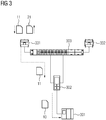
- FIG. 1 are schematically shown in transmission queues 110, 120 of a first 231 and a second WLAN station 232 of a radio communication system queued data frames 111-118, 121-128.
- This radio communication system comprises a transmitter-side first part, which in FIG. 2 and a receiver-side second part, which is shown in FIG FIG. 3 is shown.
- Both transmit queues 110, 120 are based on the same input sequence 100 of data frames 101-108 received by a first HSR / PRP redbox 202.
- the first HSR / PRP red box 202 is the one in FIG. 2 assigned first part of the radio communication system and indirectly connected via a first VLAN-capable switch 203 with the first 231 and the second WLAN station 232.
- the first HSR / PRP redbox 202 includes at least 3 communication network ports. Via a first and second communication network connection, the first HSR / PRP redbox 202 is connected redundantly to a first VLAN-capable switch 203.
- An SCADA system 201 (Supervisory Control and Data Acquisition) is connected to an interlink port, which represents a third communication network connection of the first HSR / PRP redbox 202, in the present exemplary embodiment at the management system level.
- the WLAN stations 231-232 can either play a role as a WLAN access point or as a WLAN client.
- wireless transceiver stations can also be used instead of WLAN stations for a WiMAX, UMTS, LTE mobile or other mobile network.
- FIG. 1 For an increased data throughput with respect to data frames 111-118, 121-128 transmitted via WLAN, data frames to be transmitted after duplication by means of an HSR / PRP redbox by the WLAN stations are to be transmitted within a predetermined time interval FIG. 1 no longer sent in accordance with the FIFO principle, but sorted in their transmission order according to destination MAC addresses. Within a destination MAC address, an original sequence is maintained in accordance with reception times at the respective WLAN station.
- the data frames 101, 103, 107 for the destination MAC address MAC A within the input sequence 100 in the first, third and seventh positions are placed first to third in the send queue 110 of the first WLAN station 231.
- these data frames are only ranked fourth to sixth in the send queue 120 of the second WLAN station 232.
- the second, sixth and eighth data frames 102, 106, 108 within the input sequence 100 for the destination MAC address MAC B are ranked first to third in the send queue 120 of the second WLAN station 232 ,
- these data frames are only ranked fourth to sixth in the send queue 110 of the first WLAN station 231.
- the data frame 104 for the destination MAC address MAC C which is in fourth position within the input sequence 100, is placed seventh in the transmission queue 110 of the first WLAN station 231 and eighth in the transmission queue 120 of the second WLAN station. Station queued.
- the data frame 105 which arrives fifth in the input sequence 100, for the destination MAC address MAC D becomes eighth in the transmission queue 110 of the first WLAN station 231 and ranked seventh in the send queue 120 of the second WLAN station.
- a co-ordinated send queue management ensures that mutually assigned partner WLAN stations never transmit data frames to the same destination MAC address via the two partner WLAN stations at the same time.
- the second part of the industrial communication system comprises a second HSR / PRP red box 302, which also has at least 3 communication network ports.
- the second HSR / PRP redbox 302 is connected redundantly to a second VLAN-capable switch 303.
- a sensor or actuator system 301 of an industrial automation system is connected at the field level in the present exemplary embodiment.
- This sensor or actuator system 301 can be, for example, a production robot, a drive for a conveyor system or an operator control and monitoring station on a production line.
- the second part of the industrial communication system 2 includes WLAN stations 331-332 connected to the second switch 303, which optionally also can perform a role as a WLAN access point or as a WLAN client.
- the first 203 and the second switch 303 each include a plurality of communication network terminals and a coupling element interconnecting the communication network terminals.
- a coupling element can be realized for example by a high-speed bus or a backplane switch with associated controller.
- the first 202 and second HSR / PRP red boxes 302 each have a signal processing unit connected to their communication terminals, which has a multiplexer unit for parallel routing of data frames (frames) to be transmitted to the respective first and second communication network terminals.
- a multiplexer unit duplicates data frames 10 sent by a communication or automation device that is simply connected to the industrial communication network.
- Mutually redundant data frames 11, 12 are identified by a uniform sequence number, which is assigned by the respective signal processing unit to redundantly transmitted data frames.
- the mutually redundant data frames 11, 12 are then transmitted from the respective HSR / PRP Redbox 202, 302 to the first 203 and second switch 303, respectively.
- the first 203 or second switch 303 then forward these data frames 11, 12 to a respective 231, 331 first and second WLAN station 232, 332, respectively.
- first 202 and second HSR / PRP red boxes 302 each have a redundancy handling unit for processing received data frames from respective first and second communication network ports.
- the redundancy handling unit in turn comprises a filter unit which is provided for detection and filtering of received redundant data frames.
- the respective signal processing unit is in each case assigned a memory unit which stores sequence numbers of data frames which have already been received without errors.
- the redundancy handling unit checks for consistency with an already stored sequence number.
- Data frames to be transmitted redundantly in the present exemplary embodiment are transmitted in accordance with the Parallel Redundancy Protocol. Basically, a transfer is also appropriate High-availability Seamless Redundancy possible. The following explanations apply analogously.
- Data frames transmitted by the first communication network connection of the first 202 and the second HSR / PRP redbox 302 to the respective switch 203, 303 are assigned to a first VLAN.
- data frames transmitted by the second communication network connection of the first 202 and the second HSR / PRP redbox 302 to the respective switch 203, 303 are assigned to a second VLAN.
- Data frames assigned to the first VLAN are transmitted by means of the respective first WLAN station 231, 331 via a first WLAN network with a first WLAN SSID
- data frames assigned to the second VLAN are transmitted via the respective second WLAN station 232, 332 via a second WLAN Network can be sent with a second wireless SSID.
- the first WLAN SSID and the second WLAN SSID are different.
- the first 231, 331 and second WLAN stations 232, 332 for other data traffic can also be assigned to the second or first WLAN network.
- the WLAN stations 231-233, 331-332 transmit an acknowledgment message 21 on the receiver side to a transmitter-side WLAN station 231.
- this transmits transmitter-side WLAN station 232 a drop-frame message 232 at its associated partner WLAN station 232, which is connected to the same switch 203.
- the respective partner WLAN station 232 stops sending a redundant data frame having a sequence number which is assigned to an acknowledgment message 21 received on the sender side. This can be done, for example, by deleting or discarding a redundant data frame from a send queue of the partner WLAN station take place, in particular as soon as this data frame arrives after transmission from the respective switch to the partner WLAN station.
Landscapes
- Engineering & Computer Science (AREA)
- Computer Networks & Wireless Communication (AREA)
- Signal Processing (AREA)
- Computer Security & Cryptography (AREA)
- Mobile Radio Communication Systems (AREA)
Description
Industrielle Automatisierungssysteme dienen zur Überwachung, Steuerung und Regelung von technischen Prozessen, insbesondere im Bereich Fertigungs-, Prozess- und Gebäudeautomatisierung, und ermöglichen einen Betrieb von Steuerungseinrichtungen, Sensoren, Maschinen und industriellen Anlagen, der möglichst selbständig und unabhängig von menschlichen Eingriffen erfolgen soll. Aufgrund einer ständig steigenden Bedeutung von Informationstechnik für Automatisierungssysteme, die zahlreiche vernetzte Steuerungs- bzw. Rechnereinheiten umfassen, gewinnen Verfahren zur zuverlässigen Bereitstellung von über ein Automatisierungssystem verteilten Funktionen für eine Bereitstellung von Überwachungs-, Steuerungs- und Regelungsfunktionen verstärkt an Bedeutung.Industrial automation systems are used to monitor, control and regulate technical processes, in particular in the field of manufacturing, process and building automation, and allow operation of control devices, sensors, machines and industrial facilities, which should be as independent and independent of human intervention as possible. Due to the ever increasing importance of information technology for automation systems, which include numerous networked control or computing units, gaining more and more importance for methods for reliably providing functions distributed via an automation system for providing monitoring, control and regulating functions.
Unterbrechungen von Kommunikationsverbindungen zwischen Rechnereinheiten eines industriellen Automatisierungssystems oder Automatisierungsgeräten können zu einer unerwünschten oder unnötigen Wiederholung einer Übermittlung einer Dienstanforderung führen. Dies verursacht eine zusätzliche Auslastung von Kommunikationsverbindungen des industriellen Automatisierungssystems, was zu weiteren Systemstörungen oder -fehlern führen kann. Außerdem können nicht oder nicht vollständig übermittelte Nachrichten beispielsweise einen Übergang oder Verbleib eines industriellen Automatisierungssystems in einen sicheren Betriebszustand verhindern. Dies kann schließlich zu einem Ausfall einer kompletten Produktionsanlage und einem kostspieligen Produktionsstillstand führen. Eine besondere Problematik resultiert in industriellen Automatisierungssystemen regelmäßig aus einem Meldungsverkehr mit verhältnismäßig vielen, aber relativ kurzen Nachrichten, wodurch obige Probleme verstärkt werden.Interruptions of communication links between computer units of an industrial automation system or automation devices may lead to an undesirable or unnecessary repetition of a transmission of a service request. This causes an additional utilization of communication links of the industrial automation system, which can lead to further system errors or errors. In addition, messages that are not or not completely transmitted, for example, can prevent a transition or retention of an industrial automation system into a safe operating state. This can eventually lead to a failure of a complete production plant and a costly production downtime. A particular problem arises in industrial automation systems regularly from a message traffic with relatively many, but relatively short messages, whereby the above problems are amplified.
Um Ausfälle von Kommunikationsverbindungen oder -geräten kompensieren zu können, sind Kommunikationsprotokolle, wie Media Redundancy Protocol, High-availability Seamless Redundancy oder Parallel Redundancy Protocol, für hochverfügbare, redundant betreibbare industrielle Kommunikationsnetze entwickelt worden. Media Redundancy Protocol (MSR) ist im Standard IEC 62439 definiert und ermöglicht eine Kompensation einzelner Verbindungsausfälle in Netzen mit einfacher Ringtopologie bei stoßbehafteter redundanter Übertragung von Nachrichten. Entsprechend Media Redundancy Protocol ist einem Switch mit zwei Ports innerhalb der Ringtopologie ein Redundanz-Manager zugeordnet, der das Netz auf Verbindungsausfälle überwacht und ggf. eine Schaltmaßnahme für einen Ringschluss einleitet.To be able to compensate for failures of communication links or devices, communication protocols such as Media Redundancy Protocol, High-availability Seamless Redundancy or Parallel Redundancy Protocol have been developed for high-availability, redundantly operable industrial communication networks. Media Redundancy Protocol (MSR) is defined in the IEC 62439 standard and allows compensation for individual link failures in simple ring topology networks in the event of bursty redundant message transmission. According to Media Redundancy Protocol, a switch with two ports within the ring topology is assigned a redundancy manager, which monitors the network for connection failures and if necessary initiates a switching action for a ring closure.
Stoßbehaftete Medienredundanzverfahren lassen sich grundsätzlich mit relativ geringem Aufwand realisieren. Nachteilig ist jedoch, dass einerseits Nachrichten im Fehlerfall verloren gehen können und andererseits während einer Rekonfiguration eines Kommunikationsnetzes zunächst ein Störungszustand vorliegt. Ein derartiger Störungszustand muss durch ein überlagertes Kommunikationsprotokoll, beispielsweise mittels TCP/IP auf Vermittlungs- bzw. Transportschichtebene, gesichert werden, um eine Unterbrechung einer Kommunikationsverbindung zu vermeiden.Impacted media redundancy methods can basically be implemented with relatively little effort. The disadvantage, however, is that, on the one hand, messages can be lost in the event of a fault and, on the other hand, during a reconfiguration of a communications network, there is initially a fault condition. Such a fault condition must be secured by a higher-level communication protocol, for example by means of TCP / IP at the switching or transport layer level, in order to avoid an interruption of a communication connection.
Auch PROFINET (IEC 61158 Type 10) referenziert Media Redundancy Protocol als stoßbehaftetes Medienredundanzverfahren innerhalb eines Kommunikationsnetzes mit Ringtopologie. Media Redundancy Planned Duplication (MRPD) stellt demgegenüber eine Erweiterung für eine stoßfreie Übertragung von isochronen Echtzeitdaten dar. Bei Media Redundancy Planned Duplication handelt es sich jedoch nicht um ein anwendungsneutrales stoßfreies Medienredundanzverfahren, sondern um eine PROFINET-spezifische Erweiterung.PROFINET (IEC 61158 Type 10) also references Media Redundancy Protocol as a burst media redundancy method within a ring topology communication network. In contrast, Media Redundancy Planned Duplication (MRPD) provides an extension for bumpless transfer of isochronous data Real-time data. However, Media Redundancy Planned Duplication is not an application-neutral bumpless media redundancy technique, but a PROFINET-specific extension.
High-availability Seamless Redundancy (HSR) und Parallel Redundancy Protocol (PRP) sind im Standard IEC 62439-3 definiert und ermöglichen eine stoßfreie redundante Übertragung von Nachrichten mit äußerst geringen Erholungszeiten. Entsprechend High-availability Seamless Redundancy und Parallel Redundancy Protocol wird jede Nachricht von einem sendenden Kommunikationsgerät dupliziert und auf zwei verschiedenen Wegen zu einem Empfänger geschickt. Durch ein empfängerseitiges Kommunikationsgerät werden Duplikate darstellende redundante Nachrichten aus einem empfangenen Datenstrom ausgefiltert.High-availability Seamless Redundancy (HSR) and Parallel Redundancy Protocol (PRP) are defined in the IEC 62439-3 standard and enable bumpless redundant transmission of messages with extremely short recovery times. According to High-availability Seamless Redundancy and Parallel Redundancy Protocol, each message is duplicated by a sending communication device and sent to a receiver in two different ways. By a receiver-side communication device duplicate representing redundant messages are filtered out of a received data stream.
Im Standard IEC 62439-3 sind für das Parallel Redundancy Protocol (PRP) aufgrund verhältnismäßig langer Latenzlaufzeiten in Drahtlos-Kommunikationssystemen und eines dadurch bedingten nicht-deterministischen Übertragungsverhaltens bislang ausschließlich kabelgebundene Übertragungsstrecken vorgeschrieben. In "
In
Aus
In
Zur hochverfügbaren Anbindung von Automatisierungsgeräten mit vollständig unabhängigen Ethernet-Schnittstellen innerhalb eines redundanten Komunikationsnetzes an einfach angebundene Automatisierungsgeräte wird entsprechend
Aus
In
Der vorliegenden Erfindung liegt die Aufgabe zugrunde, ein ausfallsicheres Funk-Kommunikationssystem für ein industrielles Automatisierungssystem zu schaffen, das eine effizientere Funk-Ressourcennutzung ermöglicht, ein Verfahren zu dessen Betrieb sowie geeignete Systemkomponenten anzugeben.The present invention has for its object to provide a fail-safe radio communication system for an industrial automation system, which allows a more efficient use of radio resources, specify a method for its operation and appropriate system components.
Diese Aufgabe wird erfindungsgemäß durch ein Kommunikationssystem mit den in Anspruch 1 angegebenen Merkmalen, durch ein Verfahren mit den in Anspruch 10 angegebenen Merkmalen und durch eine Funk-Transceiver-Station mit den in Anspruch 16 angegebenen Merkmalen gelöst. Vorteilhafte Weiterbildungen der vorliegenden Erfindung sind in den abhängigen Ansprüchen angegeben.This object is achieved by a communication system with the features specified in
Das erfindungsgemäße Kommunikationssystem umfasst zumindest ein erstes und ein zweites redundant an ein industrielles Kommunikationsnetz angebundenes Kommunikationsgerät mit jeweils zumindest einem ersten und einem zweiten Kommunikationsnetzanschluss. Mit dem ersten und zweiten Kommunikationsnetzanschluss ist eine Signalverarbeitungseinheit verbunden, die eine Multiplexereinheit zur parallelen Weiterleitung zu sendender Datenrahmen an beide Kommunikationsnetzanschlüsse und eine Redundanzbehandlungseinheit zur Verarbeitung von beiden Kommunikationsnetzanschlüssen empfangener Datenrahmen aufweist. Dabei umfasst die Redundanzbehandlungseinheit eine Filtereinheit, die für eine Detektion empfangener redundanter Datenrahmen ausgestaltet und eingerichtet ist, insbesondere durch entsprechende Konfiguration.The communication system according to the invention comprises at least a first and a second redundantly connected to an industrial communication network communication device, each with at least a first and a second communication network connection. Connected to the first and second communication network terminals is a signal processing unit having a multiplexer unit for forwarding data frames to be transmitted in parallel to both communication network terminals and a redundancy handling unit for processing both communication network terminals of received data frames. In this case, the redundancy treatment unit comprises a filter unit that is designed and set up for detection of received redundant data frames, in particular by appropriate configuration.
Erfindungsgemäß sind das erste und das zweite Kommunikationsgerät jeweils über ihren ersten Kommunikationsnetzanschluss mittel- oder unmittelbar mit einer jeweiligen ersten Funk-Transceiver-Station verbunden. Analog dazu sind das erste und das zweite Kommunikationsgerät jeweils über ihren zweiten Kommunikationsnetzanschluss mittel- oder unmittelbar mit einer jeweiligen zweiten Funk-Transceiver-Station verbunden. Eine mittelbare Verbindung kann beispielsweise mittels eines Switches erfolgen, an den das jeweilige Kommunikationsgerät und die jeweiligen Funk-Transceiver-Stationen angeschlossen sind. Die Funk-Transceiver-Stationen können beispielsweise einem Wireless Local Area Network, einem WiMAX-, einem UMTS-, einem LTE-Mobilfunknetz oder einem sonstigen Mobilfunknetz zugeordnet sein. Darüber hinaus sind die ersten und zweiten Funk-Transceiver-Stationen dafür ausgestaltet und eingerichtet, insbesondere konfiguriert, dass eine Reihenfolge für innerhalb eines vorgegebenen Zeitintervalls zu sendende Datenrahmen anhand den zu sendenden Datenrahmen zugeordneter Ziel-MAC-Adressen - anstelle entsprechend FIFO-Prinzip -festgelegt wird. Dabei wird die Reihenfolge innerhalb an eine ausgewählte Ziel-MAC-Adresse zu sendender Datenrahmen durch ihre Eingangsreihenfolge festgelegt. Außerdem sind die ersten und zweiten Funk-Transceiver-Stationen dafür ausgestaltet und eingerichtet, dass die mit desselben Kommunikationsgerät verbundene erste und zweite Funk-Transceiver-Station ihre Reihenfolgen für zu sendende Datenrahmen durch ein Sende-Queue-Management derart koordinieren, dass beide Funk-Transceiver-Stationen Datenrahmen niemals gleichzeitig an dieselbe Ziel-MAC-Adresse senden. Dies kann beispielsweise mittels eines Sende-Tokens oder eines Mutex, der einer gegebenen Ziel-MAC-Adresse zugeordnet ist, realisiert werden.According to the invention, the first and the second communication device are each connected via their first communication network connection directly or indirectly to a respective first radio transceiver station. Analogously, the first and the second communication device are each connected via their second communication network connection directly or indirectly to a respective second radio transceiver station. An indirect connection can be made for example by means of a switch, to which the respective communication device and the respective radio transceiver stations are connected. The radio transceiver stations may, for example, be assigned to a wireless local area network, a WiMAX, a UMTS, an LTE mobile radio network or another mobile radio network. In addition, the first and second radio transceiver stations are designed and set up, in particular configured, to set an order for data frames to be transmitted within a predetermined time interval on the basis of the target MAC addresses assigned to data frames to be sent instead of according to the FIFO principle becomes. The order within a selected destination MAC address for data frames to be transmitted is determined by their input order. In addition, the first and second radio transceiver stations configured and arranged for the first and second radio transceiver stations connected to the same communication device to coordinate their sequences of data frames to be transmitted by a transmit queue management such that both radio transceiver stations never transmit data frames send to the same destination MAC address at the same time . This can be realized, for example, by means of a send token or a mutex associated with a given destination MAC address.
Das erfindungsgemäße Funk-Kommunikationssystem bietet als Vorteil, dass die beiden Funk-Transceiver-Stationen nicht gleichzeitig mit zueinander redundantem Datenverkehr für denselben Empfänger belegt werden müssen, sondern durch entsprechende Sende-Queue-Verwaltung für unterschiedliche Empfänger zeitgleich genutzt werden können. Hierdurch ergibt sich eine effizientere Ressourcenausnutzung bzw. eine erhöhte effektive Datenübertragungsrate. Werden für beide Funk-Transceiver-Stationen unterschiedliche Frequenzbänder genutzt, ist zudem eine Wahrscheinlichkeit einer zeitgleichen Störung sehr gering.The radio communication system according to the invention offers the advantage that the two radio transceiver stations need not be occupied simultaneously with mutually redundant data traffic for the same receiver, but can be used by different send queue management for different receivers at the same time. This results in a more efficient use of resources or an increased effective data transfer rate. In addition, if different frequency bands are used for both radio transceiver stations, a probability of a simultaneous interference is also very low.
Entsprechend einer vorteilhaften Ausgestaltung der vorliegenden Erfindung sind zueinander redundante Datenrahmen durch eine einheitliche Sequenznummer gekennzeichnet. Dabei sind die Signalverarbeitungseinheiten des ersten und des zweiten Kommunikationsgeräts für eine Vergabe einer Sequenznummer an einen redundant zu übermittelnden Datenrahmen ausgestaltet und eingerichtet. Vorzugsweise sind die erste und zweite Funk-Transceiver-Station dafür ausgestaltet und eingerichtet, dass bei einem erfolgreichen Empfang eines über das erste oder zweite Funknetz gesendeten Datenrahmens empfängerseitig eine Bestätigungsmeldung an eine senderseitige Funk-Transceiver-Station übermittelt wird. Des weiteren sind die Funk-Transceiver-Stationen bevorzugt dafür ausgestaltet und eingerichtet, dass ein Senden eines redundanten Datenrahmens mit einer Sequenznummer, die einer senderseitig empfangenen Bestätigungsmeldung zugeordnet ist, unterbunden wird. Ist ein Datenrahmen beispielsweise bereits über eine schnellere Funkverbindung übertragen worden, braucht ein zu diesem redundanter Datenrahmen nicht mehr verzögert bzw. über eine langsamere Funkverbindung übertragen zu werden, sondern kann senderseitig verworfen werden. Dies ermöglicht eine effizientere Ressourcenausnutzung.According to an advantageous embodiment of the present invention, mutually redundant data frames are characterized by a uniform sequence number. In this case, the signal processing units of the first and the second communication device are designed and set up for assigning a sequence number to a data frame to be transmitted redundantly. The first and second radio transceiver stations are preferably designed and set up such that upon a successful reception of a data frame transmitted via the first or second radio network, a confirmation message is transmitted on the receiver side to a transmitter-side radio transceiver station. Furthermore, the Radio transceiver stations preferably designed and set up to prevent the transmission of a redundant data frame with a sequence number which is assigned to a confirmation message received on the transmitter side. For example, if a data frame has already been transmitted over a faster radio link, it is no longer necessary to delay or transmit it over a slower radio link to this redundant data frame, but instead it can be discarded on the transmitter side. This allows a more efficient use of resources.
Vorzugsweise erfolgt eine Übertragung redundant zu übermittelnder Datenrahmen entsprechend High-availability Seamless Redundancy bzw. entsprechend Parallel Redundancy Protocol. Dabei können das erste und zweite Kommunikationsgerät beispielsweise eine HSR- bzw. PRP-Redbox sein. Über eine solche HSR- bzw. PRP-Redbox kann jeweils ein einfach angebundenes Kommunikationsgerät mit dem industriellen Kommunikationsnetz verbunden sein.Preferably, a transmission takes place redundantly to be transmitted data frame according to High-availability Seamless Redundancy or according to Parallel Redundancy Protocol. The first and second communication device may be, for example, an HSR or PRP redbox. By way of such an HSR or PRP Redbox, a simply connected communication device can be connected to the industrial communication network.
Darüber hinaus können sich die Funk-Transceiver-Stationen bei einer Suche nach korrespondierenden Partner-Stationen derart koordinieren, dass eine Datenübertragung bei der Suche kurzzeitig unterbrochen und auf anderen Funkkanälen nach verfügbaren Partner-Stationen gesucht wird. Hierzu können zwei derselben HSR- bzw. PRP-Redbox zugeordnete Funk-Transceiver-Stationen untereinander ein Scan-Token austauschen. Durch dieses Scan-Token wird festgelegt, welche Funk-Transceiver-Station aktiv Daten überträgt und welche Funk-Transceiver-Station einen Scan nach verfügbaren Partner-Stationen durchführt, die einer jeweils anderen HSR- bzw. PRP-Redbox zugeordnet sind.In addition, the radio transceiver stations can coordinate in a search for corresponding partner stations such that a data transfer during the search is briefly interrupted and searched on other radio channels for available partner stations. For this purpose, two radio transceiver stations assigned to the same HSR or PRP redbox can exchange a scan token with one another. This scan token determines which radio transceiver station is actively transmitting data and which radio transceiver station is scanning for available partner stations that are assigned to a different HSR or PRP redbox.
Entsprechend einer weiteren Ausgestaltung des erfindungsgemäßen Funk-Kommunikationssystems sind zumindest ein erstes und ein zweites dem industriellen Kommunikationsnetz zugeordnetes Netzinfrastrukturgerät mit jeweils einer Mehrzahl von Kommunikationsnetzanschlüssen und einem die Kommunikationsnetzanschlüsse miteinander verbindenden Koppelelement vorgesehen. Die Netzinfrastrukturgeräte können beispielsweise Switches sein. Vorzugsweise ist das Koppelelement eines Netzinfrastrukturgeräts ein Hochgeschwindigkeitsbus bzw. ein Backplane Switch mit zugeordnetem Controller. Das erste Kommunikationsgerät ist über seinen ersten und zweiten Kommunikationsnetzanschluss redundant an das erste Netzinfrastrukturgerät angeschlossen, während das zweite Kommunikationsgerät über seinen ersten und zweiten Kommunikationsnetzanschluss redundant an das zweite Netzinfrastrukturgerät angeschlossen ist.According to a further embodiment of the radio communication system according to the invention, at least a first and a second network infrastructure device assigned to the industrial communication network are provided, each with a plurality of communication network connections and a coupling element interconnecting the communication network connections. The network infrastructure devices can be, for example, switches. The coupling element of a network infrastructure device is preferably a high-speed bus or a backplane switch with an associated controller. The first communication device is connected redundantly to the first network infrastructure device via its first and second communication network connection, while the second communication device is connected redundantly to the second network infrastructure device via its first and second communication network connection.
Außerdem sind das erste und zweite Kommunikationsgerät bzw. das erste und zweite Netzinfrastrukturgerät entsprechend der weiteren Ausgestaltung des erfindungsgemäßen Funk-Kommunikationssystems dafür ausgestaltet und eingerichtet, dass vom ersten Kommunikationsnetzanschluss des ersten und des zweiten Kommunikationsgeräts an das jeweilige Netzinfrastrukturgerät übermittelte Datenrahmen einem ersten virtuellen lokalen Netz zugeordnet werden und dass vom zweiten Kommunikationsnetzanschluss des ersten und des zweiten Kommunikationsgeräts an das jeweilige Netzinfrastrukturgerät übermittelte Datenrahmen einem zweiten virtuellen lokalen Netz zugeordnet werden. Die jeweiligen Funk-Transceiver-Stationen sind an die Netzinfrastrukturgeräte angeschlossen. Darüber hinaus sind die Funk-Transceiver-Stationen bzw. die Netzinfrastrukturgeräte dafür ausgestaltet und eingerichtet, dass dem ersten virtuellen lokalen Netz zugeordnete Datenrahmen mittels der jeweiligen ersten Funk-Transceiver-Station über ein erstes Funknetz gesendet werden und dass dem zweiten virtuellen lokalen Netz zugeordnete Datenrahmen mittels der jeweiligen zweiten Funk-Transceiver-Station über ein zweites Funknetz gesendet werden. Vorteilhafterweise sind das erste und zweite Funknetz mittels einer Funknetz-Kennung identifizierbar, beispielsweise mittels eines Service Set Identifier. Grundsätzlich können die ersten und zweiten Funk-Transceiver-Stationen jeweils zumindest dem ersten und zweiten Funknetz zugeordnet sein.In addition, the first and second communication device or the first and second network infrastructure device according to the further embodiment of the radio communication system according to the invention configured and set up that assigned by the first communication network connection of the first and the second communication device to the respective network infrastructure data frame assigned to a first virtual local area network and that data frames transmitted by the second communication network connection of the first and the second communication device to the respective network infrastructure device are assigned to a second virtual local network. The respective radio transceiver stations are connected to the network infrastructure devices. In addition, the radio transceiver stations or the network infrastructure devices are designed and set up for this purpose, that data frames assigned to the first virtual local area network are transmitted via the first radio transceiver station via a first radio network and the second virtual local area network associated data frames are transmitted by means of the respective second radio transceiver station via a second radio network. Advantageously, the first and second radio network can be identified by means of a radio network identifier, for example by means of a service set identifier. In principle, the first and second radio transceiver stations can each be assigned to at least the first and second radio network.
Entsprechend dem erfindungsgemäßen Verfahren zum Betrieb eines Funk-Kommunikationssystems für ein industrielles Automatisierungssystem werden zumindest ein erstes und ein zweites Kommunikationsgerät redundant an ein industrielles Kommunikationsnetz angebunden. Dabei weisen das erste und zweite Kommunikationsgerät jeweils zumindest einen ersten und einem zweiten Kommunikationsnetzanschluss und eine mit dem ersten und zweiten Kommunikationsnetzanschluss verbundene Signalverarbeitungseinheit auf. Die Signalverarbeitungseinheit leitet zu sendende Datenrahmen parallel an beide Kommunikationsnetzanschlüsse weiter und detektiert von beiden Kommunikationsnetzanschlüssen empfangene redundante Datenrahmen.According to the inventive method for operating a radio communication system for an industrial automation system, at least a first and a second communication device are connected redundantly to an industrial communication network. In this case, the first and second communication device each have at least a first and a second communication network connection and a signal processing unit connected to the first and second communication network connection. The signal processing unit forwards data frames to be transmitted in parallel to both communication network connections and detects redundant data frames received by both communication network connections.
Erfindungsgemäß sind das erste und das zweite Kommunikationsgerät jeweils über ihren ersten Kommunikationsnetzanschluss mittel- oder unmittelbar mit einer jeweiligen ersten Funk-Transceiver-Station verbunden. In entsprechender Weise sind das erste und das zweite Kommunikationsgerät jeweils über ihren zweiten Kommunikationsnetzanschluss mittel- oder unmittelbar mit einer jeweiligen zweiten Funk-Transceiver-Station verbunden. Die ersten und zweiten Funk-Transceiver-Stationen legen eine Reihenfolge für innerhalb eines vorgegebenen Zeitintervalls zu sendende Datenrahmen anhand den zu sendenden Datenrahmen zugeordneter Ziel-MAC-Adressen fest. Dabei wird die Reihenfolge innerhalb an eine ausgewählte Ziel-MAC-Adresse zu sendender Datenrahmen durch ihre Eingangsreihenfolge festgelegt. Darüber hinaus koordinieren die ersten und zweiten Funk-Transceiver-Stationen, die mit demselben Kommunikationsgerät verbunden sind, ihre Reihenfolgen durch ein Sende-Queue-Management für zu sendende Datenrahmen derart, dass beide Funk-Transceiver-Stationen Datenrahmen niemals gleichzeitig an dieselbe Ziel-MAC-Adresse senden. According to the invention, the first and the second communication device are each connected via their first communication network connection directly or indirectly to a respective first radio transceiver station. In a corresponding manner, the first and the second communication device are each connected via their second communication network connection directly or indirectly to a respective second radio transceiver station. The first and second radio transceiver stations set an order for data frames to be transmitted within a predetermined time interval based on the destination MAC addresses assigned to data frames to be transmitted. At this time, the order within a selected destination MAC address becomes the data frame to be transmitted by its input order established. In addition, the first and second radio transceiver stations, which are connected to the same communication device, coordinate their orders by a transmission queue management for data frames to be transmitted such that both radio transceiver stations never simultaneously send data frames to the same destination MAC Send address.
Vorzugsweise werden zueinander redundante Datenrahmen durch eine einheitliche Sequenznummer gekennzeichnet. Dabei vergeben die Signalverarbeitungseinheiten des ersten und des zweiten Kommunikationsgeräts eine Sequenznummer an einen redundant zu übermittelnden Datenrahmen. Entsprechend einer besonders bevorzugten Ausgestaltung des erfindungsgemäßen Verfahrens übermitteln die erste und zweite Funk-Transceiver-Station bei einem erfolgreichen Empfang eines über das erste oder zweite Funknetz gesendeten Datenrahmens empfängerseitig eine Bestätigungsmeldung an eine senderseitige Funk-Transceiver-Station. Vorteilhafterweise unterbinden die Funk-Transceiver-Stationen bzw. die Netzinfrastrukturgeräte ein Senden eines redundanten Datenrahmens mit einer Sequenznummer, die einer senderseitig empfangenen Bestätigungsmeldung zugeordnet ist.Preferably, mutually redundant data frames are identified by a uniform sequence number. In this case, the signal processing units of the first and the second communication device assign a sequence number to a data frame to be transmitted redundantly. According to a particularly preferred embodiment of the method according to the invention, the first and second radio transceiver stations transmit a confirmation message to a transmitter-end radio transceiver station on the receiver side upon successful reception of a data frame transmitted via the first or second radio network. Advantageously, the radio transceiver stations or the network infrastructure devices prevent transmission of a redundant data frame having a sequence number that is assigned to a confirmation message received by the transmitter.
Die vorliegende Erfindung wird nachfolgend an einem Ausführungsbeispiel anhand der Zeichnung näher erläutert. Es zeigt
Figur 1- eine schematische Darstellung von Sende-Queues einer ersten und zweiten WLAN-Station eines Funk-Kommunikationssystems für ein industrielles Automatisierungssystem,
Figur 2- einen ersten Teil eines Funk-Kommunikationssystems für ein industrielles Automatisierungssystem mit einer ersten HSR/PRP-Redbox, einem ersten VLAN-fähigen Switch und mehreren an den ersten Switch angeschlossenen WLAN-Transceiver-Stationen,
Figur 3- einen zweiten Teil eines Funk-Kommunikationssystems für ein industrielles Automatisierungssystem mit einer ersten HSR/PRP-Redbox, einem zweiten VLAN-fähigen Switch und mehreren an den zweiten Switch angeschlossenen WLAN-Transceiver-Stationen.
- FIG. 1
- a schematic representation of send queues of a first and second WLAN station of a radio communication system for an industrial automation system,
- FIG. 2
- a first part of a radio communication system for an industrial automation system with a first HSR / PRP Redbox, a first VLAN-capable Switch and several WLAN transceiver stations connected to the first switch,
- FIG. 3
- a second part of a radio communication system for an industrial automation system with a first HSR / PRP Redbox, a second VLAN-capable switch and several WLAN transceiver stations connected to the second switch.
In
Die WLAN-Stationen 231-232 können wahlweise eine Rolle als WLAN-Access-Point oder als WLAN-Client wahrnehmen. Anstelle von WLAN-Stationen können grundsätzlich auch Funk-Transceiver-Stationen für ein WiMAX-, ein UMTS-, ein LTE-Mobilfunknetz oder ein sonstiges Mobilfunknetz verwendet werden. Nachfolgende Ausführungen gelten hierfür analog. Für einen erhöhten Datendurchsatz hinsichtlich per WLAN übermittelter Datenrahmen 111-118, 121-128 werden innerhalb eines vorgegebenen Zeitintervalls zu sendende Datenrahmen nach Duplizierung mittels einer HSR/PRP-Redbox durch die WLAN-Stationen gemäß
Beispielsweise werden die innerhalb der Eingangssequenz 100 an erster, dritter und siebter Stelle stehenden Datenrahmen 101, 103, 107 für die Ziel-MAC-Adresse MAC A an erster bis dritter Stelle in die Sende-Queue 110 der ersten WLAN-Station 231 eingereiht. In die Sende-Queue 120 der zweiten WLAN-Station 232 werden diese Datenrahmen dagegen erst an vierter bis sechster Stelle eingereiht. In umgekehrter Weise werden die innerhalb der Eingangssequenz 100 an zweiter, sechster und achter Stelle stehenden Datenrahmen 102, 106, 108 für die Ziel-MAC-Adresse MAC B an erster bis dritter Stelle in die Sende-Queue 120 der zweiten WLAN-Station 232 eingereiht. In die Sende-Queue 110 der ersten WLAN-Station 231 werden diese Datenrahmen dagegen erst an vierter bis sechster Stelle eingereiht. Der innerhalb der Eingangssequenz 100 an vierter Stelle stehende Datenrahmen 104 für die Ziel-MAC-Adresse MAC C wird an siebter Stelle in die Sende-Queue 110 der ersten WLAN-Station 231 und an achter Stelle in die Sende-Queue 120 der zweiten WLAN-Station eingereiht. In analoger Weise wird der innerhalb der Eingangssequenz 100 an fünfter Stelle stehende Datenrahmen 105 für die Ziel-MAC-Adresse MAC D wird an achter Stelle in die Sende-Queue 110 der ersten WLAN-Station 231 und an siebter Stelle in die Sende-Queue 120 der zweiten WLAN-Station eingereiht. Insgesamt wird an einander zugeordneten Partner-WLAN-Stationen durch ein koordiniertes Sende-Queue-Management sichergestellt, dass über die beiden Partner-WLAN-Stationen niemals gleichzeitig Datenrahmen an dieselbe Ziel-MAC-Adresse übermittelt werden.For example, the data frames 101, 103, 107 for the destination MAC address MAC A within the
Entsprechend
Der erste 203 und der zweite Switch 303 umfassen jeweils eine Mehrzahl von Kommunikationsnetzanschlüssen und ein die Kommunikationsnetzanschlüsse miteinander verbindendes Koppelelement. Ein solches Koppelelement kann beispielsweise durch einen Hochgeschwindigkeitsbus bzw. einen Backplane Switch mit zugeordnetem Controller realisiert sein.The first 203 and the
Die erste 202 und zweite HSR/PRP-Redbox 302 weisen jeweils eine mit ihren Kommunikationsanschlüssen verbundene Signalverarbeitungseinheit auf, die eine Multiplexereinheit zur parallelen Weiterleitung zu sendender Datenrahmen (Frames) an den jeweiligen ersten und zweiten Kommunikationsnetzanschluss aufweist. Durch eine Multiplexereinheit werden von einem einfach an das industrielle Kommunikationsnetz angebundenen Kommunikations- bzw. Automatisierungsgerät gesendete Datenrahmen 10 dupliziert. Zueinander redundante Datenrahmen 11, 12 werden durch eine einheitliche Sequenznummer gekennzeichnet, die durch die jeweilige Signalverarbeitungseinheit an redundant zu übermittelnde Datenrahmen vergeben wird. Die zueinander redundanten Datenrahmen 11, 12 werden dann von der jeweiligen HSR/PRP-Redbox 202, 302 an den ersten 203 bzw. zweiten Switch 303 übermittelt. Der erste 203 bzw. zweite Switch 303 leiten diese Datenrahmen 11, 12 dann an eine jeweilige 231, 331 erste bzw. zweite WLAN-Station 232, 332 weiter.The first 202 and second HSR / PRP
Darüber hinaus weisen die erste 202 und zweite HSR/PRP-Redbox 302 jeweils eine Redundanzbehandlungseinheit zur Verarbeitung vom jeweiligen ersten und zweiten Kommunikationsnetzanschluss empfangener Datenrahmen auf. Die Redundanzbehandlungseinheit umfasst wiederum eine Filtereinheit, die für eine Detektion und Ausfilterung empfangener redundanter Datenrahmen vorgesehen ist. Des weiteren ist der jeweiligen Signalverarbeitungseinheit jeweils eine Speichereinheit zugeordnet, die Sequenznummern bereits fehlerfrei empfangener Datenrahmen speichert. Bei Empfang eines neuen Datenrahmens führt die Redundanzbehandlungseinheit eine Überprüfung auf Übereinstimmung mit einer bereits gespeicherten Sequenznummer durch. Redundant zu übermittelnde Datenrahmen werden im vorliegenden Ausführungsbeispiel entsprechend Parallel Redundancy Protocol übertragen. Grundsätzlich ist auch eine Übertragung entsprechend High-availability Seamless Redundancy möglich. Nachfolgende Ausführungen gelten hierfür analog.Moreover, the first 202 and second HSR / PRP
Vom ersten Kommunikationsnetzanschluss der ersten 202 und der zweiten HSR/PRP-Redbox 302 an den jeweiligen Switch 203, 303 übermittelte Datenrahmen werden einem ersten VLAN zugeordnet. Analog dazu werden vom zweiten Kommunikationsnetzanschluss der ersten 202 und der zweiten HSR/PRP-Redbox 302 an den jeweiligen Switch 203, 303 übermittelte Datenrahmen einem zweiten VLAN zugeordnet. Dem ersten VLAN zugeordnete Datenrahmen werden mittels der jeweiligen ersten WLAN-Station 231, 331 über ein erstes WLAN-Netz mit einer ersten WLAN-SSID gesendet, während dem zweiten VLAN zugeordnete Datenrahmen mittels der jeweiligen zweiten WLAN-Station 232, 332 über ein zweites WLAN-Netz mit einer zweiten WLAN-SSID gesendet werden. Dabei sind die erste WLAN-SSID und die zweite WLAN-SSID voneinander verschieden. Grundsätzlich können die ersten 231, 331 und zweiten WLAN-Stationen 232, 332 für sonstigen Datenverkehr auch dem zweiten bzw. ersten WLAN-Netz zugeordnet sein.Data frames transmitted by the first communication network connection of the first 202 and the second HSR /
Bei einem erfolgreichen Empfang eines über das erste oder zweite WLAN-Netz gesendeten Datenrahmens übermitteln die WLAN-Stationen 231-233, 331-332 empfängerseitig eine Acknowledge-Meldung 21 an eine senderseitige WLAN-Station 231. Bei Empfang einer Acknowledgement-Meldung 21 übermittelt diese senderseitige WLAN-Station 232 eine Drop-Frame-Meldung 232 an ihrer zugeordneten Partner-WLAN-Station 232, die an denselben Switch 203 angeschlossen ist. Auf eine solche Drop-Frame-Meldung 22 unterbindet die jeweilige Partner-WLAN-Station 232 ein Senden eines redundanten Datenrahmens mit einer Sequenznummer, die einer senderseitig empfangenen Acknowledgement-Meldung 21 zugeordnet ist. Dies kann beispielsweise durch ein Löschen bzw. Verwerfen eines redundanten Datenrahmens aus einer Sende-Queue der Partner-WLAN-Station erfolgen, insbesondere sobald dieser Datenrahmen nach Übermittlung vom jeweiligen Switch an der Partner-WLAN-Station eintrifft.In the case of a successful reception of a data frame transmitted via the first or second WLAN network, the WLAN stations 231-233, 331-332 transmit an
Claims (16)
- Radio communication system for an industrial automation system having- at least a first (202) and a second (302) communication device redundantly connected to an industrial communication network and each having- at least a first and a second communication network port,- a signal processing unit connected to the first and second communication network ports and having a multiplexer unit for the parallel forwarding of data frames to be sent to the two communication network ports and a redundancy handling unit for processing data frames received from the two communication network ports, wherein the redundancy handling unit comprises a filter unit configured and set up for detection of received redundant data frames (11, 12),wherein- the first (202) and the second (302) communication device are each indirectly or directly connected, by means of their first communication network port, to a respective first radio transceiver station (231, 331),- the first (202) and the second (302) communication device are each indirectly or directly connected, via their second communication network port, to a respective second radio transceiver station (232, 332),
characterized in that- the first (231, 331) and second (232, 332) radio transceiver stations are configured and set up so that a sequence for data frames (111-118, 121-128) to be sent within a prescribed interval of time is stipulated on the basis of destination MAC addresses associated with the data frames to be sent, wherein the sequence is stipulated within data frames to be sent to a selected destination MAC address by means of the order in which said data frames are received,- the first (231, 331) and second (232, 332) radio transceiver stations are configured and set up so that the first and second radio transceiver stations connected to the same communication device coordinate their sequences for data frames to be sent by means of send queue management such that the two radio transceiver stations never send data frames to the same destination MAC address at the same time. - Communication system according to Claim 1,
in which data frames that are redundant with respect to one another are characterized by a standard sequence number, and in which the signal processing units of the first and second communication devices are configured and set up for allocation of a sequence number to a data frame that is to be transmitted redundantly. - Communication system according to Claim 2,
in which the first (231, 331) and second (232, 332) radio transceiver stations are configured and set up so that successful reception of a data frame sent via a radio network results in the receiver end transmitting a confirmation message (21) to a radio transceiver station at the transmitter end. - Communication system according to Claim 3,
in which the radio transceiver stations (231-232, 331-332) are configured and set up so that sending of a redundant data frame with a sequence number associated with a confirmation message (21) received at the transmitter end is prevented. - Communication system according to one of Claims 1 to 4,
in which data frames to be transmitted redundantly are transmitted in accordance with High-availability Seamless Redundancy and/or in accordance with Parallel Redundancy Protocol. - Communication system according to Claim 5,
in which the first and second communication devices are an HSR and/or PRP RedBox. - Communication system according to Claim 6,
in which the first (202) and second (302) communication devices each connect a singly connected communication device (201, 301) to the industrial communication network. - Communication system according to one of Claims 1 to 7,
in which the radio transceiver stations are associated with at least a wireless local area network, a WiMAX, UMTS or LTE mobile radio network or another mobile radio network. - Communication system according to one of Claims 1 to 8,
in which at least a first and a second network infrastructure device associated with the industrial communication network are provided, each having a plurality of communication network ports and a coupling element connecting the communication network ports to one another, in which the first communication device is redundantly connected, via its first and second communication network ports, to the first network infrastructure device, in which the second communication device is redundantly connected, via its first and second communication network ports, to the second network infrastructure device, in which the first and second communication devices and/or the first and second network infrastructure devices are configured and set up so that data frames transmitted from the first communication network port of the first and second communication devices to the respective network infrastructure device are associated with a first virtual local area network and that data frames transmitted from the second communication network port of the first and second communication devices to the respective network infrastructure device are associated with a second virtual local area network, in which the respective radio transceiver stations are connected to the network infrastructure devices and in which the radio transceiver stations and/or the network infrastructure devices are configured and set up so that data frames associated with the first virtual local area network are sent by means of the respective first radio transceiver station via a first radio network and that data frames associated with the second virtual local area network are sent by means of the respective second radio transceiver station via a second radio network. - Method for operating a radiocommunication system for an industrial automation system, in which- at least a first (202) and a second (302) communication device are redundantly connected to an industrial communication network, wherein the first and second communication devices each have- at least a first and a second communication network port and- a signal processing unit connected to the first and second communication network ports that forwards data frames to be sent to the two communication network ports in parallel and detects redundant data frames (11, 12) received from the two communication network ports,wherein- the first (202) and the second (302) communication device are each indirectly or directly connected, via their first communication network port, to a respective first radio transceiver station (231, 331),- the first (202) and the second (302) communication device are each indirectly or directly connected, via their second communication network port, to a respective second radio transceiver station (232, 332),
characterized in that- the first (231, 331) and second (232, 332) radio transceiver stations stipulate a sequence for data frames (111-118, 121-128) to be sent within a prescribed interval of time on the basis of destination MAC addresses associated with the data frames to be sent, wherein the sequence is stipulated within data frames to be sent to a selected destination MAC address by means of the order in which said data frames are received,- the first (231, 331) and second (232, 332) radio transceiver stations connected to the same communication device coordinate their sequences for data frames to be sent by means of send queue management such that the two radio transceiver stations never send data frames to the same destination MAC address at the same time. - Method according to Claim 10,
in which data frames that are redundant with respect to one another are characterized by a standard sequence number and in which the signal processing units of the first and second communication devices allocate a sequence number to a data frame that is to be transmitted redundantly. - Method according to Claim 11,
in which the first (231, 331) and second (232, 332) radio transceiver stations, on successful reception of a data frame sent via a radio network, use the receiver end to transmit a confirmation message (21) to a radio transceiver station at the transmitter end. - Method according to Claim 12,
in which the radio transceiver stations (231-232, 331-332) prevent sending of a redundant data frame with a sequence number associated with a confirmation message (21) received at the transmitter end. - Method according to one of Claims 10 to 13,
in which data frames to be transmitted redundantly are transmitted in accordance with High-availability Seamless Redundancy and/or in accordance with Parallel Redundancy Protocol. - Method according to one of Claims 10 to 14,
in which at least a first and a second network infrastructure device associated with the industrial communication network are provided that each have a plurality of communication network ports and a coupling element connecting the communication network ports to one another, in which the first communication device is redundantly connected, via its first and second communication network ports, to the first network infrastructure device, in which the second communication device is redundantly connected, via its first and second communication network ports, to the second network infrastructure device, in which data frames transmitted from the first communication network port of the first and second communication devices to the respective network infrastructure device are associated with a first virtual local area network and data frames transmitted from the second communication network port of the first and second communication devices to the respective network infrastructure device are associated with a second virtual local area network, in which the respective radio transceiver stations are connected to the network infrastructure devices, wherein data frames associated with the first virtual local area network are sent by means of the respective first radio transceiver station via a first radio network and data frames associated with the second virtual local area network are sent by means of the respective second radio transceiver station via a second radio network. - Radio transceiver station for performing a method according to one of Claims 10 to 15,
characterized in that the radio transceiver station (231-232, 331-332) is configured and set up so that a sequence for data frames (111-118, 121-128) to be sent is stipulated on the basis of destination MAC addresses associated with the data frames to be sent, wherein the sequence is stipulated within data frames to be sent to a selected destination MAC address by means of the order in which said data frames are received, and that a first (231, 331) and second (232, 332) radio transceiver station connected to the same communication device coordinate their sequences for data frames to be sent by means of send queue management such that the two radio transceiver stations never send data frames to the same destination MAC address at the same time.
Priority Applications (4)
| Application Number | Priority Date | Filing Date | Title |
|---|---|---|---|
| EP16157795.2A EP3211962B1 (en) | 2016-02-29 | 2016-02-29 | Radio communication system for an industrial automation system, method of operating the same and radio transceiver station |
| CN201780013671.3A CN108702804B (en) | 2016-02-29 | 2017-01-26 | Wireless communication system for an industrial automation system, method for the operation thereof |
| PCT/EP2017/051626 WO2017148626A1 (en) | 2016-02-29 | 2017-01-26 | Radio communication system for an industrial automation system, method for operating said communication system, and radio transceiver station |
| US16/080,919 US10484238B2 (en) | 2016-02-29 | 2017-01-26 | Radio communication system for an industrial automation system, method for operating said radio communication system, and radio transceiver station |
Applications Claiming Priority (1)
| Application Number | Priority Date | Filing Date | Title |
|---|---|---|---|
| EP16157795.2A EP3211962B1 (en) | 2016-02-29 | 2016-02-29 | Radio communication system for an industrial automation system, method of operating the same and radio transceiver station |
Publications (2)
| Publication Number | Publication Date |
|---|---|
| EP3211962A1 EP3211962A1 (en) | 2017-08-30 |
| EP3211962B1 true EP3211962B1 (en) | 2018-09-12 |
Family
ID=55453049
Family Applications (1)
| Application Number | Title | Priority Date | Filing Date |
|---|---|---|---|
| EP16157795.2A Active EP3211962B1 (en) | 2016-02-29 | 2016-02-29 | Radio communication system for an industrial automation system, method of operating the same and radio transceiver station |
Country Status (4)
| Country | Link |
|---|---|
| US (1) | US10484238B2 (en) |
| EP (1) | EP3211962B1 (en) |
| CN (1) | CN108702804B (en) |
| WO (1) | WO2017148626A1 (en) |
Families Citing this family (5)
| Publication number | Priority date | Publication date | Assignee | Title |
|---|---|---|---|---|
| EP3518471B1 (en) | 2018-01-24 | 2020-07-29 | Siemens Aktiengesellschaft | Radio communication system for an industrial automation system and method for operating a radio communication system |
| EP3522605A1 (en) | 2018-01-31 | 2019-08-07 | Siemens Aktiengesellschaft | Radio communication system for an industrial automation system and method for operating a radio communication system |
| WO2020035148A1 (en) * | 2018-08-17 | 2020-02-20 | Telefonaktiebolaget Lm Ericsson (Publ) | Control system |
| DE112019007888T5 (en) * | 2019-11-11 | 2022-09-01 | Siemens Canada Limited | Network device for providing redundancy in an industrial network |
| US11258888B2 (en) * | 2019-11-11 | 2022-02-22 | Cisco Technology, Inc. | Parallel redundancy protocol (PRP) using non-overlapping resource unit (RU) groupings on a radio |
Family Cites Families (19)
| Publication number | Priority date | Publication date | Assignee | Title |
|---|---|---|---|---|
| US20020089959A1 (en) * | 2001-01-11 | 2002-07-11 | Fischer Michael A. | System and method for providing a selectable retry strategy for frame-based communications |
| TWI227616B (en) * | 2001-11-20 | 2005-02-01 | Hitachi Ltd | Packet communication device, packet communication system, packet communication module, data processor and data transmission system |
| US7457973B2 (en) * | 2003-06-20 | 2008-11-25 | Texas Instruments Incorporated | System and method for prioritizing data transmission and transmitting scheduled wake-up times to network stations based on downlink transmission duration |
| US20050030894A1 (en) * | 2003-08-04 | 2005-02-10 | Stephens Adrian P. | Techniques for channel access and transmit queue selection |
| DE102006010513B4 (en) * | 2006-03-07 | 2011-12-29 | Infineon Technologies Ag | Communication device, radio communication arrangement and method for transmitting information from a first radio communication device to a second radio communication device |
| US7885639B1 (en) * | 2006-06-29 | 2011-02-08 | Symantec Corporation | Method and apparatus for authenticating a wireless access point |
| JP5163900B2 (en) * | 2006-10-06 | 2013-03-13 | 日本電気株式会社 | COMMUNICATION DEVICE, COMMUNICATION SYSTEM, COMMUNICATION METHOD, AND COMMUNICATION PROGRAM |
| US8560012B2 (en) * | 2009-11-30 | 2013-10-15 | Panasonic Corporation | Communication device |
| JP5497529B2 (en) * | 2010-05-13 | 2014-05-21 | 日本電気株式会社 | Network relay apparatus and QoS control method |
| DE102011004064A1 (en) | 2011-02-14 | 2012-08-16 | Siemens Aktiengesellschaft | Ring topology intermediate network and method for establishing a network connection between two network domains |
| CN102082695B (en) * | 2011-03-07 | 2013-01-02 | 中控科技集团有限公司 | Hot standby redundancy network system and redundancy realization method |
| ES2556381T3 (en) * | 2011-06-04 | 2016-01-15 | Alcatel Lucent | A planning concept |
| DE102011082965A1 (en) | 2011-09-19 | 2013-01-24 | Siemens Aktiengesellschaft | Method for operating a network arrangement and network arrangement |
| DE102012209509A1 (en) | 2012-06-06 | 2013-12-12 | Hirschmann Automation And Control Gmbh | Apparatus for transmitting data between mobile station and stationary receiver at global system for mobile communication (GSM) network, has stationary receiver that is redundantly connected by wire to networks |
| EP2712124B1 (en) | 2012-09-24 | 2015-04-01 | Siemens Aktiengesellschaft | Redundant industrial communication system and method for its operation |
| EP2936692A1 (en) | 2012-12-21 | 2015-10-28 | Hirschmann Automation and Control GmbH | Method for redundantly and securely transferring data from a data source to a data sink |
| WO2014187893A1 (en) * | 2013-05-24 | 2014-11-27 | Hirschmann Automation And Control Gmbh | Wireless redbox comprising a timing splitter |
| DE102013211406A1 (en) | 2013-06-18 | 2014-12-18 | Siemens Aktiengesellschaft | Communication device for connecting a field device of an industrial automation system with a fail-safe control unit and industrial automation system |
| US9961702B2 (en) * | 2015-07-15 | 2018-05-01 | Macau University Of Science And Technology | Method and system for contention queuing using a queue-based MAC protocol |
-
2016
- 2016-02-29 EP EP16157795.2A patent/EP3211962B1/en active Active
-
2017
- 2017-01-26 WO PCT/EP2017/051626 patent/WO2017148626A1/en active Application Filing
- 2017-01-26 US US16/080,919 patent/US10484238B2/en active Active
- 2017-01-26 CN CN201780013671.3A patent/CN108702804B/en active Active
Non-Patent Citations (1)
| Title |
|---|
| None * |
Also Published As
| Publication number | Publication date |
|---|---|
| EP3211962A1 (en) | 2017-08-30 |
| US10484238B2 (en) | 2019-11-19 |
| CN108702804B (en) | 2020-10-27 |
| CN108702804A (en) | 2018-10-23 |
| WO2017148626A1 (en) | 2017-09-08 |
| US20190116086A1 (en) | 2019-04-18 |
Similar Documents
| Publication | Publication Date | Title |
|---|---|---|
| EP3211838B1 (en) | Redundant industrial communication system, method of operating same and radio transceiver station | |
| EP2688249B1 (en) | Method for message transmission in a redundant industrial communication network and communication device for a redundant industrial communication network | |
| EP3211962B1 (en) | Radio communication system for an industrial automation system, method of operating the same and radio transceiver station | |
| EP2712124B1 (en) | Redundant industrial communication system and method for its operation | |
| EP3427538B1 (en) | Redundant industrial communication system, method of operating the same and wireless device station | |
| EP2693700B1 (en) | Method for message transmission in a redundant industrial communication network and communication device for a redundant industrial communication network | |
| EP2661023B1 (en) | Communication device for a redundant industrial communication network and method for operating a communication device | |
| EP3155763B1 (en) | Redundant transmission of data telegrams in communication networks having ring topology | |
| EP2637362B1 (en) | Bus participant device for connection to a line-redundant, serial data bus and method for controlling the communication of a bus participant with a line-redundant, serial data bus | |
| EP2838220A1 (en) | Method for the redundant transmission of messages in an industrial communication network and communication device | |
| EP3854028B1 (en) | Method for detecting network subscribers in an automation network and automation network | |
| EP3343303B1 (en) | Radio communication system and method for an industrial automation system | |
| EP2670078B1 (en) | Communication device for a redundant industrial communication network and method for operating a communication device | |
| EP2704370B1 (en) | Method for message transmission in a redundant industrial communication network and communication device for a redundant industrial communication network | |
| EP3518471B1 (en) | Radio communication system for an industrial automation system and method for operating a radio communication system | |
| DE102013211406A1 (en) | Communication device for connecting a field device of an industrial automation system with a fail-safe control unit and industrial automation system | |
| EP2680503B1 (en) | Communication device for a redundant industrial communication network and method for operating a communication device | |
| EP3718342B1 (en) | Radio communication system for an industrial automation system and method for operating a radio communication system | |
| EP3301523A1 (en) | Redundant operable communications system for an industrial automation system and method of operation | |
| EP2854345B1 (en) | Method and coupling communication device for message delivery in a redundantly operable industrial communication network | |
| EP3629550A1 (en) | Method for transmitting data within an industrial communication system and coupling communication device | |
| WO2019001828A1 (en) | Method for message transmission in a redundantly operable industrial communications network and communications device for the implementation thereof | |
| EP2269321B1 (en) | Method and device for data processing and system comprising said device | |
| WO2009129852A1 (en) | Method and device for redundancy control of base stations and system comprising said device | |
| EP2562960A1 (en) | Redundant data transmission method in a communication network |
Legal Events
| Date | Code | Title | Description |
|---|---|---|---|
| PUAI | Public reference made under article 153(3) epc to a published international application that has entered the european phase |
Free format text: ORIGINAL CODE: 0009012 |
|
| STAA | Information on the status of an ep patent application or granted ep patent |
Free format text: STATUS: THE APPLICATION HAS BEEN PUBLISHED |
|
| AK | Designated contracting states |
Kind code of ref document: A1 Designated state(s): AL AT BE BG CH CY CZ DE DK EE ES FI FR GB GR HR HU IE IS IT LI LT LU LV MC MK MT NL NO PL PT RO RS SE SI SK SM TR |
|
| AX | Request for extension of the european patent |
Extension state: BA ME |
|
| STAA | Information on the status of an ep patent application or granted ep patent |
Free format text: STATUS: REQUEST FOR EXAMINATION WAS MADE |
|
| 17P | Request for examination filed |
Effective date: 20180205 |
|
| RBV | Designated contracting states (corrected) |
Designated state(s): AL AT BE BG CH CY CZ DE DK EE ES FI FR GB GR HR HU IE IS IT LI LT LU LV MC MK MT NL NO PL PT RO RS SE SI SK SM TR |
|
| GRAP | Despatch of communication of intention to grant a patent |
Free format text: ORIGINAL CODE: EPIDOSNIGR1 |
|
| STAA | Information on the status of an ep patent application or granted ep patent |
Free format text: STATUS: GRANT OF PATENT IS INTENDED |
|
| INTG | Intention to grant announced |
Effective date: 20180405 |
|
| GRAS | Grant fee paid |
Free format text: ORIGINAL CODE: EPIDOSNIGR3 |
|
| GRAA | (expected) grant |
Free format text: ORIGINAL CODE: 0009210 |
|
| STAA | Information on the status of an ep patent application or granted ep patent |
Free format text: STATUS: THE PATENT HAS BEEN GRANTED |
|
| AK | Designated contracting states |
Kind code of ref document: B1 Designated state(s): AL AT BE BG CH CY CZ DE DK EE ES FI FR GB GR HR HU IE IS IT LI LT LU LV MC MK MT NL NO PL PT RO RS SE SI SK SM TR |
|
| REG | Reference to a national code |
Ref country code: GB Ref legal event code: FG4D Free format text: NOT ENGLISH |
|
| REG | Reference to a national code |
Ref country code: CH Ref legal event code: EP |
|
| REG | Reference to a national code |
Ref country code: IE Ref legal event code: FG4D Free format text: LANGUAGE OF EP DOCUMENT: GERMAN |
|
| REG | Reference to a national code |
Ref country code: DE Ref legal event code: R096 Ref document number: 502016001890 Country of ref document: DE |
|
| REG | Reference to a national code |
Ref country code: AT Ref legal event code: REF Ref document number: 1042129 Country of ref document: AT Kind code of ref document: T Effective date: 20181015 |
|
| REG | Reference to a national code |
Ref country code: NL Ref legal event code: MP Effective date: 20180912 |
|
| REG | Reference to a national code |
Ref country code: LT Ref legal event code: MG4D |
|
| PG25 | Lapsed in a contracting state [announced via postgrant information from national office to epo] |
Ref country code: LT Free format text: LAPSE BECAUSE OF FAILURE TO SUBMIT A TRANSLATION OF THE DESCRIPTION OR TO PAY THE FEE WITHIN THE PRESCRIBED TIME-LIMIT Effective date: 20180912 Ref country code: SE Free format text: LAPSE BECAUSE OF FAILURE TO SUBMIT A TRANSLATION OF THE DESCRIPTION OR TO PAY THE FEE WITHIN THE PRESCRIBED TIME-LIMIT Effective date: 20180912 Ref country code: BG Free format text: LAPSE BECAUSE OF FAILURE TO SUBMIT A TRANSLATION OF THE DESCRIPTION OR TO PAY THE FEE WITHIN THE PRESCRIBED TIME-LIMIT Effective date: 20181212 Ref country code: FI Free format text: LAPSE BECAUSE OF FAILURE TO SUBMIT A TRANSLATION OF THE DESCRIPTION OR TO PAY THE FEE WITHIN THE PRESCRIBED TIME-LIMIT Effective date: 20180912 Ref country code: NO Free format text: LAPSE BECAUSE OF FAILURE TO SUBMIT A TRANSLATION OF THE DESCRIPTION OR TO PAY THE FEE WITHIN THE PRESCRIBED TIME-LIMIT Effective date: 20181212 Ref country code: GR Free format text: LAPSE BECAUSE OF FAILURE TO SUBMIT A TRANSLATION OF THE DESCRIPTION OR TO PAY THE FEE WITHIN THE PRESCRIBED TIME-LIMIT Effective date: 20181213 Ref country code: RS Free format text: LAPSE BECAUSE OF FAILURE TO SUBMIT A TRANSLATION OF THE DESCRIPTION OR TO PAY THE FEE WITHIN THE PRESCRIBED TIME-LIMIT Effective date: 20180912 |
|
| PG25 | Lapsed in a contracting state [announced via postgrant information from national office to epo] |
Ref country code: HR Free format text: LAPSE BECAUSE OF FAILURE TO SUBMIT A TRANSLATION OF THE DESCRIPTION OR TO PAY THE FEE WITHIN THE PRESCRIBED TIME-LIMIT Effective date: 20180912 Ref country code: LV Free format text: LAPSE BECAUSE OF FAILURE TO SUBMIT A TRANSLATION OF THE DESCRIPTION OR TO PAY THE FEE WITHIN THE PRESCRIBED TIME-LIMIT Effective date: 20180912 Ref country code: AL Free format text: LAPSE BECAUSE OF FAILURE TO SUBMIT A TRANSLATION OF THE DESCRIPTION OR TO PAY THE FEE WITHIN THE PRESCRIBED TIME-LIMIT Effective date: 20180912 |
|
| PG25 | Lapsed in a contracting state [announced via postgrant information from national office to epo] |
Ref country code: CZ Free format text: LAPSE BECAUSE OF FAILURE TO SUBMIT A TRANSLATION OF THE DESCRIPTION OR TO PAY THE FEE WITHIN THE PRESCRIBED TIME-LIMIT Effective date: 20180912 Ref country code: RO Free format text: LAPSE BECAUSE OF FAILURE TO SUBMIT A TRANSLATION OF THE DESCRIPTION OR TO PAY THE FEE WITHIN THE PRESCRIBED TIME-LIMIT Effective date: 20180912 Ref country code: EE Free format text: LAPSE BECAUSE OF FAILURE TO SUBMIT A TRANSLATION OF THE DESCRIPTION OR TO PAY THE FEE WITHIN THE PRESCRIBED TIME-LIMIT Effective date: 20180912 Ref country code: NL Free format text: LAPSE BECAUSE OF FAILURE TO SUBMIT A TRANSLATION OF THE DESCRIPTION OR TO PAY THE FEE WITHIN THE PRESCRIBED TIME-LIMIT Effective date: 20180912 Ref country code: IS Free format text: LAPSE BECAUSE OF FAILURE TO SUBMIT A TRANSLATION OF THE DESCRIPTION OR TO PAY THE FEE WITHIN THE PRESCRIBED TIME-LIMIT Effective date: 20190112 Ref country code: ES Free format text: LAPSE BECAUSE OF FAILURE TO SUBMIT A TRANSLATION OF THE DESCRIPTION OR TO PAY THE FEE WITHIN THE PRESCRIBED TIME-LIMIT Effective date: 20180912 Ref country code: PL Free format text: LAPSE BECAUSE OF FAILURE TO SUBMIT A TRANSLATION OF THE DESCRIPTION OR TO PAY THE FEE WITHIN THE PRESCRIBED TIME-LIMIT Effective date: 20180912 |
|
| PG25 | Lapsed in a contracting state [announced via postgrant information from national office to epo] |
Ref country code: SM Free format text: LAPSE BECAUSE OF FAILURE TO SUBMIT A TRANSLATION OF THE DESCRIPTION OR TO PAY THE FEE WITHIN THE PRESCRIBED TIME-LIMIT Effective date: 20180912 Ref country code: PT Free format text: LAPSE BECAUSE OF FAILURE TO SUBMIT A TRANSLATION OF THE DESCRIPTION OR TO PAY THE FEE WITHIN THE PRESCRIBED TIME-LIMIT Effective date: 20190112 Ref country code: SK Free format text: LAPSE BECAUSE OF FAILURE TO SUBMIT A TRANSLATION OF THE DESCRIPTION OR TO PAY THE FEE WITHIN THE PRESCRIBED TIME-LIMIT Effective date: 20180912 |
|
| REG | Reference to a national code |
Ref country code: DE Ref legal event code: R097 Ref document number: 502016001890 Country of ref document: DE |
|
| PLBE | No opposition filed within time limit |
Free format text: ORIGINAL CODE: 0009261 |
|
| STAA | Information on the status of an ep patent application or granted ep patent |
Free format text: STATUS: NO OPPOSITION FILED WITHIN TIME LIMIT |
|
| PG25 | Lapsed in a contracting state [announced via postgrant information from national office to epo] |
Ref country code: DK Free format text: LAPSE BECAUSE OF FAILURE TO SUBMIT A TRANSLATION OF THE DESCRIPTION OR TO PAY THE FEE WITHIN THE PRESCRIBED TIME-LIMIT Effective date: 20180912 |
|
| 26N | No opposition filed |
Effective date: 20190613 |
|
| PG25 | Lapsed in a contracting state [announced via postgrant information from national office to epo] |
Ref country code: SI Free format text: LAPSE BECAUSE OF FAILURE TO SUBMIT A TRANSLATION OF THE DESCRIPTION OR TO PAY THE FEE WITHIN THE PRESCRIBED TIME-LIMIT Effective date: 20180912 |
|
| REG | Reference to a national code |
Ref country code: CH Ref legal event code: PL |
|
| PG25 | Lapsed in a contracting state [announced via postgrant information from national office to epo] |
Ref country code: LU Free format text: LAPSE BECAUSE OF NON-PAYMENT OF DUE FEES Effective date: 20190228 Ref country code: MC Free format text: LAPSE BECAUSE OF FAILURE TO SUBMIT A TRANSLATION OF THE DESCRIPTION OR TO PAY THE FEE WITHIN THE PRESCRIBED TIME-LIMIT Effective date: 20180912 |
|
| REG | Reference to a national code |
Ref country code: BE Ref legal event code: MM Effective date: 20190228 |
|
| REG | Reference to a national code |
Ref country code: IE Ref legal event code: MM4A |
|
| PG25 | Lapsed in a contracting state [announced via postgrant information from national office to epo] |
Ref country code: LI Free format text: LAPSE BECAUSE OF NON-PAYMENT OF DUE FEES Effective date: 20190228 Ref country code: CH Free format text: LAPSE BECAUSE OF NON-PAYMENT OF DUE FEES Effective date: 20190228 |
|
| PG25 | Lapsed in a contracting state [announced via postgrant information from national office to epo] |
Ref country code: IE Free format text: LAPSE BECAUSE OF NON-PAYMENT OF DUE FEES Effective date: 20190228 |
|
| PG25 | Lapsed in a contracting state [announced via postgrant information from national office to epo] |
Ref country code: BE Free format text: LAPSE BECAUSE OF NON-PAYMENT OF DUE FEES Effective date: 20190228 |
|
| PG25 | Lapsed in a contracting state [announced via postgrant information from national office to epo] |
Ref country code: TR Free format text: LAPSE BECAUSE OF FAILURE TO SUBMIT A TRANSLATION OF THE DESCRIPTION OR TO PAY THE FEE WITHIN THE PRESCRIBED TIME-LIMIT Effective date: 20180912 |
|
| PG25 | Lapsed in a contracting state [announced via postgrant information from national office to epo] |
Ref country code: MT Free format text: LAPSE BECAUSE OF FAILURE TO SUBMIT A TRANSLATION OF THE DESCRIPTION OR TO PAY THE FEE WITHIN THE PRESCRIBED TIME-LIMIT Effective date: 20180912 |
|
| GBPC | Gb: european patent ceased through non-payment of renewal fee |
Effective date: 20200229 |
|
| PG25 | Lapsed in a contracting state [announced via postgrant information from national office to epo] |
Ref country code: GB Free format text: LAPSE BECAUSE OF NON-PAYMENT OF DUE FEES Effective date: 20200229 |
|
| PG25 | Lapsed in a contracting state [announced via postgrant information from national office to epo] |
Ref country code: CY Free format text: LAPSE BECAUSE OF FAILURE TO SUBMIT A TRANSLATION OF THE DESCRIPTION OR TO PAY THE FEE WITHIN THE PRESCRIBED TIME-LIMIT Effective date: 20180912 |
|
| PG25 | Lapsed in a contracting state [announced via postgrant information from national office to epo] |
Ref country code: HU Free format text: LAPSE BECAUSE OF FAILURE TO SUBMIT A TRANSLATION OF THE DESCRIPTION OR TO PAY THE FEE WITHIN THE PRESCRIBED TIME-LIMIT; INVALID AB INITIO Effective date: 20160229 |
|
| REG | Reference to a national code |
Ref country code: AT Ref legal event code: MM01 Ref document number: 1042129 Country of ref document: AT Kind code of ref document: T Effective date: 20210228 |
|
| PG25 | Lapsed in a contracting state [announced via postgrant information from national office to epo] |
Ref country code: AT Free format text: LAPSE BECAUSE OF NON-PAYMENT OF DUE FEES Effective date: 20210228 |
|
| PG25 | Lapsed in a contracting state [announced via postgrant information from national office to epo] |
Ref country code: MK Free format text: LAPSE BECAUSE OF FAILURE TO SUBMIT A TRANSLATION OF THE DESCRIPTION OR TO PAY THE FEE WITHIN THE PRESCRIBED TIME-LIMIT Effective date: 20180912 |
|
| PGFP | Annual fee paid to national office [announced via postgrant information from national office to epo] |
Ref country code: IT Payment date: 20240221 Year of fee payment: 9 Ref country code: FR Payment date: 20240226 Year of fee payment: 9 |
|
| PGFP | Annual fee paid to national office [announced via postgrant information from national office to epo] |
Ref country code: DE Payment date: 20240418 Year of fee payment: 9 |